Embed Size (px)
Citation preview

Int. J. Fatigue Vol. 20, No. 6, pp. 413–431, 1997 1998 The Boeing Company. Published by Elsevier Science Ltd
Printed in Great Britain0142–1123/98/$19.00+.00
PII: S0142-1123(97)00029-7
Fatigue issues in aircraft maintenance andrepairs
Ulf G. Goranson
Boeing Commercial Airplane Group, Seattle, WA, USA(Received 10 February 1997)
Many design considerations are involved in ensuring structural integrity of Boeing jet transports, whichhave common design features validated by extensive analyses, tests, and service performance. Designingfor continued structural integrity in the presence of damage such as fatigue or corrosion is an evolutionaryprocess. Performance demands, increasing structural complexity, and aging fleet reassessments haverequired development of standards suitable for application by large teams of engineers. This presentationis focused on such methods with special emphasis on practical fatigue reliability considerations.Durability evaluations are based on quantitative structural fatigue ratings which incorporate reliabilityconsiderations for test data reduction and fleet performance predictions. Fatigue damage detectionassessments are based on detection reliability estimates coupled to damage growth and residual strengthevaluations. Data are presented to airline operators on detection check forms which permit efficientmaintenance planning to achieve required fatigue damage detection reliability levels. 1998 TheBoeing Company. Published by Elsevier Science Ltd.
(Keywords: fatigue and damage tolerance; damage detection reliability; airline maintenance planning)
OVERVIEW
Criteria and procedures used in commercial jet trans-port design and manufacture over the last four decadeshave resulted in fail-safe/damage-tolerant structureswith a credible safety record,Figure 1. Advancementsin the capability to characterize structural performanceby analysis have spurred adaptation of traditionalfatigue and fracture mechanics technologies with largetest and service databases to achieve development oftechnology standards over the last two decades. MajorBoeing efforts have been focused on capturing lessonslearned for future continuous design improvements withstandardized durability and damage tolerance checking
Figure 1 Safety record – worldwide commercial jet fleet
This paper was originally published in JIJF19 Supp. 1, pp. 3–21.
413
procedures similar to traditional strength checking pro-cedures. The challenge of successfully implementingtechnology standards hinges on a practical balancebetween simplicity and technical credibility aimed atproviding structural engineers with useful andservice/test validated analysis tools. This paper providesfundamental principles behind durability and damagetolerance technology standards, as well as examples oftest and service validation.
DESIGN CONSIDERATIONS
Structural integrityTwo basic structural integrity issues must be
addressed. The first is to design and verify the ultimatestrength of the undamaged structure for specified designmaneuvers, gusts, flutter, ground loads, and pressuriz-ation. The second is to design the structure to sustainfail-safe loads with limited damage for a period ofservice prior to detection and repair. All Boeing jettransports are designed to this fail-safe principle, whichrequires fail-safe load capability at all times and resto-ration of the structure to ultimate load capability afterdamage detection. The fail-safe load factor is 2.5 g formaneuver design conditions, and an additional safetyfactor of 1.5 is applied to obtain the ultimate loadrequirement. The fail-safe (limit) load levels are selec-ted to represent conditions that may occur once in alifetime for a fleet of airplanes. Design gust levels arebased on a similar remote probability of occurrencecriterion. Static strength design criteria existing today,

414 U. G. Goranson
including the factor of safety, have worked well, andconcerns about static overload failures have essentiallybeen eliminated in present-day commercial airplanes.
Several sources of damage must be evaluated toensure structural safety during service. Both accidentaldamage and environmental deterioration are randomevents during the operational life of the airplane, andmaintenance requirements must reflect inspectability forthese types of damage. Fatigue damage is a cumulativeprocess, and some cracking is expected in large fleetsdesigned to reach an economic life goal with highreliability. Consequently, supplemental fatigue damageinspections may be required for older airplanes. Theinspectability and accessibility characteristics of thestructure must be such that general visual methods ofdamage detection can be confidently employed formost of the structure. Directed inspections involvingsophisticated damage detection equipment may beacceptable in areas where inaccessibility dictatesinfrequent inspection.
Structural durabilityInteraction between structural damage tolerance and
durability characteristics must be recognized in thedesign, manufacturing, and operation of modern jettransports. Design evolution and maintenance require-ments are motivated by both safety and economicconcerns. Damage tolerance is primarily governed bycertification requirements, while durability character-istics mainly influence the airplane cost of ownershipand are dictated by the requirements of a competitiveinternational market. There is no limit to the servicelife of damage-tolerant (fail-safe) airplane structures,provided the necessary inspections are carried out alongwith timely repairs and comprehensive corrosion pre-vention programs. Since operational efficiency isimpacted by the cost and frequency of repair, durabilitymay limit the productive life of the structure.
Fatigue tests of components or the entire airframeare extremely valuable in the early life of a givenmodel, but proof of quality stems from the accumulatedexperience of maturing fleets,Figure 2. The BoeingCommercial Airplanes durability system was developedin the early 1970s to serve as a corporate memory ofpast design,Figure 3. Highlighted key parameters pro-vide the means of timely extension and transfer ofexperience to new design and/or operating usage. TheBoeing fleet is surveyed continuously and the infor-
Figure 2 Boeing commercial jet fleet summary
Figure 3 Boeing technology standards development
mation is summarized in terms of service-demonstratedfatigue lives of various components.
Damage toleranceCertification of commercial jet transports requires
damage-tolerant designs in all instances where they canbe used without unreasonable penalty. The technicalcapability has now evolved to use damage growth todetermine inspection requirements, which in the pastwere based on service experience. Appropriate multiplesite damage must be considered in both new designand structural reassessments of older models.
Damage tolerance comprises three distinct elementsof equal importance for achieving the desired levelof safety:
I Damage limit – the maximum damage, includingmultiple secondary cracks, that the structure cansustain under limit load conditions;
I Damage growth – the interval of damage pro-gression, from the detection threshold to damagelimit; it varies with the magnitude of operating loads,sequence of loads, and environmental influences;
I Inspection program – a sequence of inspections ofa fleet of airplanes with methods and intervals selec-ted to achieve timely detection of damage.
These elements of damage tolerance are merged atBoeing Commercial Airplanes by a Damage ToleranceRating (DTR) system to provide a quantitative measureof fatigue damage detection reliability,Figure 4.
Figure 4 Damage detection evaluation
415Aircraft maintenance and repair
STRUCTURAL DURABILITY ASSESSMENTS
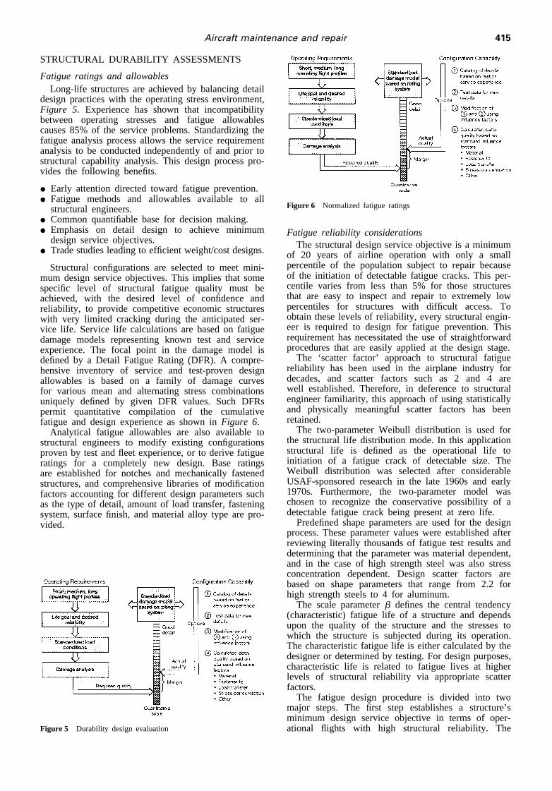
Fatigue ratings and allowablesLong-life structures are achieved by balancing detail
design practices with the operating stress environment,Figure 5. Experience has shown that incompatibilitybetween operating stresses and fatigue allowablescauses 85% of the service problems. Standardizing thefatigue analysis process allows the service requirementanalysis to be conducted independently of and prior tostructural capability analysis. This design process pro-vides the following benefits.
I Early attention directed toward fatigue prevention.I Fatigue methods and allowables available to all
structural engineers.I Common quantifiable base for decision making.I Emphasis on detail design to achieve minimum
design service objectives.I Trade studies leading to efficient weight/cost designs.
Structural configurations are selected to meet mini-mum design service objectives. This implies that somespecific level of structural fatigue quality must beachieved, with the desired level of confidence andreliability, to provide competitive economic structureswith very limited cracking during the anticipated ser-vice life. Service life calculations are based on fatiguedamage models representing known test and serviceexperience. The focal point in the damage model isdefined by a Detail Fatigue Rating (DFR). A compre-hensive inventory of service and test-proven designallowables is based on a family of damage curvesfor various mean and alternating stress combinationsuniquely defined by given DFR values. Such DFRspermit quantitative compilation of the cumulativefatigue and design experience as shown inFigure 6.
Analytical fatigue allowables are also available tostructural engineers to modify existing configurationsproven by test and fleet experience, or to derive fatigueratings for a completely new design. Base ratingsare established for notches and mechanically fastenedstructures, and comprehensive libraries of modificationfactors accounting for different design parameters suchas the type of detail, amount of load transfer, fasteningsystem, surface finish, and material alloy type are pro-vided.
Figure 5 Durability design evaluation
Figure 6 Normalized fatigue ratings
Fatigue reliability considerationsThe structural design service objective is a minimum
of 20 years of airline operation with only a smallpercentile of the population subject to repair becauseof the initiation of detectable fatigue cracks. This per-centile varies from less than 5% for those structuresthat are easy to inspect and repair to extremely lowpercentiles for structures with difficult access. Toobtain these levels of reliability, every structural engin-eer is required to design for fatigue prevention. Thisrequirement has necessitated the use of straightforwardprocedures that are easily applied at the design stage.
The ‘scatter factor’ approach to structural fatiguereliability has been used in the airplane industry fordecades, and scatter factors such as 2 and 4 arewell established. Therefore, in deference to structuralengineer familiarity, this approach of using statisticallyand physically meaningful scatter factors has beenretained.
The two-parameter Weibull distribution is used forthe structural life distribution mode. In this applicationstructural life is defined as the operational life toinitiation of a fatigue crack of detectable size. TheWeibull distribution was selected after considerableUSAF-sponsored research in the late 1960s and early1970s. Furthermore, the two-parameter model waschosen to recognize the conservative possibility of adetectable fatigue crack being present at zero life.
Predefined shape parameters are used for the designprocess. These parameter values were established afterreviewing literally thousands of fatigue test results anddetermining that the parameter was material dependent,and in the case of high strength steel was also stressconcentration dependent. Design scatter factors arebased on shape parameters that range from 2.2 forhigh strength steels to 4 for aluminum.
The scale parameterb defines the central tendency(characteristic) fatigue life of a structure and dependsupon the quality of the structure and the stresses towhich the structure is subjected during its operation.The characteristic fatigue life is either calculated by thedesigner or determined by testing. For design purposes,characteristic life is related to fatigue lives at higherlevels of structural reliability via appropriate scatterfactors.
The fatigue design procedure is divided into twomajor steps. The first step establishes a structure’sminimum design service objective in terms of oper-ational flights with high structural reliability. The
416 U. G. Goranson
second step determines the structural fatigue qualityrequired to attain this design objective. Scatter factorsare used in both steps.
The first step uses a factor known as the FatigueReliability Factor (FRF). This factor has been nor-malized so that a value of unity translates to a mini-mum level of reliability of 95% over the structure’soperational lifetime. FRF= 1 is limited to structuresin which fatigue cracks are easily detected and repaired.Structural engineers are required to use FRFs that areincreasingly greater than unity when establishing lifegoals for structures that are increasingly difficult toinspect and repair. This simple approach results in themore difficult structures being designed for longerlives. Therefore, at any time during an airplane’s oper-ational lifetime, a difficult-to-inspect/repair structuralpart would have less expectation of fatigue cracking,i.e. higher reliability, than an easy-to-inspect/repairpart.
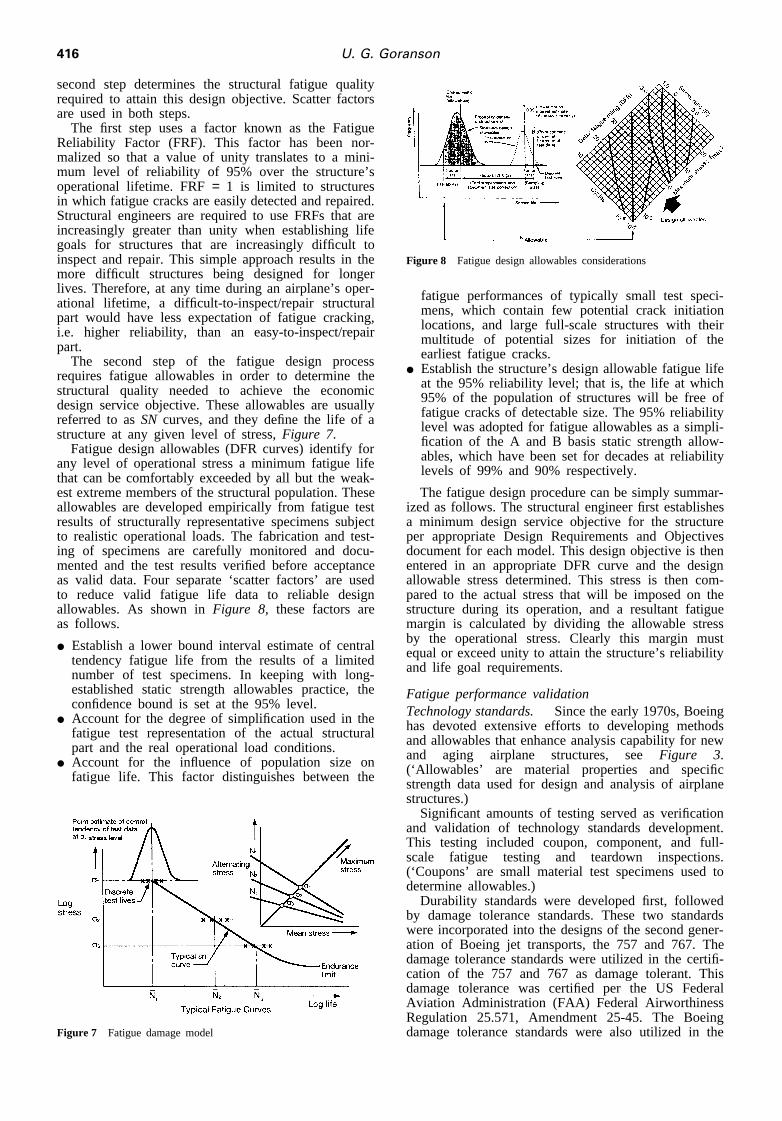
The second step of the fatigue design processrequires fatigue allowables in order to determine thestructural quality needed to achieve the economicdesign service objective. These allowables are usuallyreferred to asSN curves, and they define the life of astructure at any given level of stress,Figure 7.
Fatigue design allowables (DFR curves) identify forany level of operational stress a minimum fatigue lifethat can be comfortably exceeded by all but the weak-est extreme members of the structural population. Theseallowables are developed empirically from fatigue testresults of structurally representative specimens subjectto realistic operational loads. The fabrication and test-ing of specimens are carefully monitored and docu-mented and the test results verified before acceptanceas valid data. Four separate ‘scatter factors’ are usedto reduce valid fatigue life data to reliable designallowables. As shown inFigure 8, these factors areas follows.
I Establish a lower bound interval estimate of centraltendency fatigue life from the results of a limitednumber of test specimens. In keeping with long-established static strength allowables practice, theconfidence bound is set at the 95% level.
I Account for the degree of simplification used in thefatigue test representation of the actual structuralpart and the real operational load conditions.
I Account for the influence of population size onfatigue life. This factor distinguishes between the
Figure 7 Fatigue damage model
Figure 8 Fatigue design allowables considerations
fatigue performances of typically small test speci-mens, which contain few potential crack initiationlocations, and large full-scale structures with theirmultitude of potential sizes for initiation of theearliest fatigue cracks.
I Establish the structure’s design allowable fatigue lifeat the 95% reliability level; that is, the life at which95% of the population of structures will be free offatigue cracks of detectable size. The 95% reliabilitylevel was adopted for fatigue allowables as a simpli-fication of the A and B basis static strength allow-ables, which have been set for decades at reliabilitylevels of 99% and 90% respectively.
The fatigue design procedure can be simply summar-ized as follows. The structural engineer first establishesa minimum design service objective for the structureper appropriate Design Requirements and Objectivesdocument for each model. This design objective is thenentered in an appropriate DFR curve and the designallowable stress determined. This stress is then com-pared to the actual stress that will be imposed on thestructure during its operation, and a resultant fatiguemargin is calculated by dividing the allowable stressby the operational stress. Clearly this margin mustequal or exceed unity to attain the structure’s reliabilityand life goal requirements.
Fatigue performance validationTechnology standards. Since the early 1970s, Boeinghas devoted extensive efforts to developing methodsand allowables that enhance analysis capability for newand aging airplane structures, seeFigure 3.(‘Allowables’ are material properties and specificstrength data used for design and analysis of airplanestructures.)
Significant amounts of testing served as verificationand validation of technology standards development.This testing included coupon, component, and full-scale fatigue testing and teardown inspections.(‘Coupons’ are small material test specimens used todetermine allowables.)
Durability standards were developed first, followedby damage tolerance standards. These two standardswere incorporated into the designs of the second gener-ation of Boeing jet transports, the 757 and 767. Thedamage tolerance standards were utilized in the certifi-cation of the 757 and 767 as damage tolerant. Thisdamage tolerance was certified per the US FederalAviation Administration (FAA) Federal AirworthinessRegulation 25.571, Amendment 25-45. The Boeingdamage tolerance standards were also utilized in the

417Aircraft maintenance and repair
Figure 9 Major airframe fatigue tests
Supplemental Inspection Documents of aging airplaneprograms for the Boeing 707, 727, 737, and 747.
Since the early 1970s, corrosion has been recognizedas one of the dominant factors in the inspection andmaintenance activities of airline operations. Boeing hasdevoted extensive resources to the technology standardsdevelopment in the areas of corrosion prevention andcorrosion control. Expanded corrosion coverage, as aresult of the corrosion standards development, has beenincorporated into the production lines of all currentproduction airplanes as well as the Aging Fleet Struc-tures Working Groups. These groups include represen-tatives from airframe manufacturers, airline operators,and regulatory agencies.
Figure 9 illustrates the significance of durabilitystandards development to the structural improvementprocess. For example, the second generation 757 and767 were tested totwice their respective Design ServiceObjectives (DSOs) in flight cycles; improved testingtechnology allowed this testing to be completed in lesstime than it took to test the first generation 747 to itsoneDSO in flight cycles. More significantly, the designchanges identified in the 757 and the 767 fatiguetesting in two DSO flight cycles are far fewer thanthe design changes identified for the 747 during fatiguetesting for its one DSO in flight cycles. This improve-ment was possible because durability technology stan-dards were incorporated into the original designs ofboth the 757 and 767.
Another measurement for the effectiveness of thedesign improvements is ‘maintenance labor hours perairplane’ compared for the initial 10 years of operationfor each model,Figures 10 and 11 show significantorder of magnitude improvements between first andsecond generation wide and standard body airplanes.
Figure 10 747/767 service bulletin: labor hours after 10 years ofservice to address corrosion and fatigue
Figure 11 727/737/757 service bulletin: labor hours after 10 yearsof service to address corrosion and fatigue
These improvements are a result of implementation oflessons learned from past design practices for new air-planes.
Full-scale fatigue testing. Full-scale fatigue testingof airplanes is a major part of structural performancedata development. In addition to providing the vali-dation of aircraft design concepts, full-scale fatiguetesting is often used to identify any preventative main-tenance actions for the fleet, if the fatigue testing isdone at the time of certification of a new model ofjet transport (which is often the case at Boeing).
Figure 12 shows the minimum DSO in flight cyclesand the full-scale fatigue testing in flight cycles. Itmay be seen fromFigure 12 that full-scale fatiguetesting is generally accomplished to twice the minimumDSO, with two exceptions. The first exception is themodel 727, which was originally fatigue tested to itsDSO of 60,000 flight cycles. However, approximatelytwo years ago, a 727 airplane with 47,000 accumulatedflight cycles was acquired and the fuselage cyclicpressure tested to an additional 76,000 cycles. Thesecond exception is the model 747, which was alsooriginally fatigue tested to the DSO of 20,000 flightcycles. As in the case of the 727, a 747 airplane with20,000 accumulated flight cycles was acquired and thefuselage cyclic pressure tested to an additional 20,000cycles. In addition, the fuselage sections 41 and 42 ofthe derivative model 747-400 were cyclic pressuretested to 60,000 cycles, representing three DSOs.
Teardown inspections. Since the introduction ofthe 707, several teardown inspections and evaluations
Figure 12 Full-scale fatigue test programs

418 U. G. Goranson
of high-time airplanes have been conducted as part ofa continuing assessment of airplane structure. Theseinspections permit a detailed examination of structuralperformance, and provide much useful information forforecasting future structural maintenance requirements.Sophisticated inspection techniques, capable of findingsmaller cracks than typically found during routine air-line inspections, are used on the disassembled structure.Teardowns also provide an excellent database for calib-rating analysis tools, and developing structural modifi-cations on future production airplanes, if required.Major teardown inspections supplementing normal fleetsurveillance activities have been conducted on severalmodels:P 707 wing plus center section 1965P 707 wing 1968P 707 wing plus center section and 1973fuselageP 707 empennage 1978P 727 forward fuselage 1978P 737 wing plus center section, forward 1987fuselage, and empennageP 737 aft fuselage 1988P 747 wing and empennage 1989P 747 fuselage 1991P 727 wing and empennage 1994P 727 fuselage 1995
Concerns related to an increased number of airplanesbeing used beyond their original design life objectiveshave spurred further activities to obtain airframesretired from service for teardown inspections. Boeingwill continue to monitor the aging fleet to verify theeffectiveness of preventative modifications incorporatedas retrofit on older models and/or new model pro-duction improvements. Findings will be disseminatedto operators by service bulletins as required and incor-porated in maintenance recommendations.
Fleet surveys. The aging fleet surveys by engin-eering teams were initiated in 1986 to gain a betterunderstanding of the condition of structures and sys-tems and to observe the effectiveness of corrosionprevention features and other corrosion control actionstaken by the operators,Figure 13. All manufacturerscontinually review reported service data and other first-hand information from customer airlines in order topromote safe and economic operation of the worldwidefleet. These surveys were primarily prompted by the
Figure 13 Boeing fleet surveys
projected upward trend in airplane age towards andbeyond original design service objectives.
The initial fleet surveys showed that the majority ofthe airplanes were well maintained and in relativelygood condition. However, there were a number ofairplanes whose condition showed that finding cor-rosion discrepancies and repairing them was acceptedpractice and little or no attempt was made to applyany preventative measures. From the surveys and somesimilar incidents it became apparent that some airplaneswere continually operating with significant structuralcorrosion and that this was on the increase as airplanesage. This in turn could significantly influence thefatigue cracking and damage tolerance capability ofprincipal structural elements. Boeing formed a specialCorrosion Task Force in 1988 and held meetings withairline maintenance executives as a result of these sur-veys.
Service-demonstrated fatigue lives.The commer-cial jet fleet is used as a large group of specimensloaded in real-life environments to demonstrate service-demonstrated fatigue life and to predict future fatigueperformance. This fleet represents a database of over8000 delivered airplanes, with a total fleet experienceexceeding 150 million flight cycles, and daily utiliz-ation exceeding 23,000 flights, seeFigure 2.
Where a statistically significant number of fatiguecracks have been reported in a fleet, maximum likeli-hood estimates of the Weibull shape and scale para-meters are used to determine fleet-demonstrated DFRvalues. This provides a means of relating serviceexperience for one model to other models with differentutilization characteristics. Significant fleet findings,often augmented by extensive teardown inspections,are used to modify fatigue methods and allowablesdescribed previously. When no fatigue cracks havebeen observed, a simpler approach based on the designshape parameter is used to estimate service-demon-strated lives. Such information provides a fundamentalcheck and balance for the fatigue analysis system, andnew design and/or redesign evaluations can be relatedto accumulated fleet performance,Figure 14.
DAMAGE TOLERANCE ASSESSMENTS
Jet transports are designed to be damage tolerant, aconcept that evolved from the fail-safe design principleintroduced in the 1950s. The ability to a analyzedamaged structure has improved steadily through more
Figure 14 Service-demonstrated fatigue lives

419Aircraft maintenance and repair
sophisticated application of fracture mechanics. Timelydetection of damage is the ultimate control in ensuringstructural safety. However, traditional damage growthand residual strength evaluations have failed to incor-porate damage detection parameters that influencemaintenance planning.
The effects of accidental, environmental, and fatiguedamage must be assessed to achieve a balanced inspec-tion program. Of these, fatigue damage, characterizedby the initiation and subsequent growth of a crack, isthe most amenable to rigorous analytical treatment.Major efforts during the last 15 years have focused onestablishing quantitative damage detection rating sys-tems that measure the efficiency of inspection pro-grams. Extensive statistical evaluations of reported ser-vice data have resulted in estimates of damagedetection reliability for different inspection methods.
Fatigue damage detection is normally considered interms of a single event involving inspection for a givensize of crack with a specified method. However, airlinemaintenance practices consist of multiple inspectionlevels, varying inspection intervals, and differentmethods of inspection. In addition, fatigue cracking isgenerally found on more than one airplane in the fleetwithin a relatively short period of time. This multi-plicity of events significantly influences the timelydetection of fatigue damage and needs to be reflectedin damage detection assessments. It must be shownthat there is a high probability of detecting fatiguedamage in the fleet before such damage reduces air-plane residual strength below specified levels. A DTRsystem suitable for ensuring timely detection of fatiguedamage in the fleet was developed to accommodatethese concepts, seeFigures 3 and 4.
Elements of damage toleranceThe key objective for airplane structures designed
to the damage tolerance concept has always been tocarry regulatory fail-safe loads until detection andrepair of any fatigue cracks, corrosion, or accidentaldamage occurring in service. The ability to analyzedamaged structures has progressed significantly duringthe last 20 years through the evolution of fracturemechanics. Assessments now consider residual strength,damage growth, interactive multiple damage sites andquantitative structural maintenance evaluations. Struc-tural maintenance is the cornerstone for ensuring con-tinued airworthiness of damage-tolerant structures.
Residual strength. The maximum allowable dam-age that a structure can sustain at a critical fail-safelevel is the key to the level of damage growth andinspection needed to ensure damage detection. Built-up airplane structures consist of multiple sheet, stiff-ener, and fastener elements. Interaction between thesecracked and uncracked elements causes significantredistribution of stresses. Failures are often precipitatedby local exhaustion of plastic strain capability of themost critical elements, and/or net section failuresinvolving a mixture of fracture mechanics and tran-sitional behavior in some elements,Figure 15.
Crack growth. The rate of damage propagation isa function of material properties, structural configur-ation, environment, crack length of primary and sec-ondary cracks, and operating stress exposure. Damage
Figure 15 Residual strength evaluation
Figure 16 Crack growth evaluation
detection assessments require crack growth data fromdetection threshold lengths to the allowable damagedetermined by residual strength analyses. Use of nor-malized damage models for calculating relative growthper flight, including load sequence effects, permitsseparation of the material, geometry, and stress para-meters,Figure 16.
Damage detection. Both accidental damage andmost forms of environmental damage can be consideredas random events that can occur at any time duringthe operational life of an airplane. Fatigue damageis characterized by cumulative progression relating toairplane usage measured in flights. Detection ratingshave been developed for accidental and environmentaldamage. A quantitative fatigue damage detection ratingsystem is known as the DTR system. Damage detectionis a function of fleet size, number of cracks, andnumber and type of inspections,Figure 17.
Figure 17 Damage detection

420 U. G. Goranson
Structural maintenance considerations
Structural maintenance and inspections are the cor-nerstones of continuing airworthiness of jet transportstructures. The advent of fracture mechanics technologyhas accelerated the knowledge for determination ofcrack growth rates and maximum allowable damage atlimit load conditions. The research community hasexpanded the understanding and modeling of thesestructural characteristics. Although elastic–plasticanalyses have their place, the added accuracy is oftennot consistent with the accuracy of other significantparameters governing residual strength. Significantunderstanding exists today to properly plan fatigue andcrack growth tests in order to recognize sequenceeffects caused by spectrum loads. While analysis mod-els can yield reasonable correlation with laboratoryloading environments and simplified structural con-figurations, it is easy to have large uncertainties dueto local load redistributions in cracked structures, flawshapes, cracking patterns and a host of external andenvironmental characterization problems. While pro-gress must be encouraged, it is truly necessary to payattention to the overall sensitivity of stress histories andanalysis assumptions in the final answer. In summary,prediction of fatigue crack growth for a host of com-plex structural details within a factor of 2 is not alwaysas easy as advertised by complex models.
The practising structural maintenance engineer ischarged with development of inspection programs fromthe time of airplane introduction into service. Threeprincipal forms of structural damage must be evaluatedto achieve a balanced structural inspection programfor timely detection of environmental deterioration,accidental damage, and fatigue damage.
Environmental deterioration actually involves twoforms of damage, corrosion and stress corrosion. Cor-rosion may or may not be time- and/or usage-depen-dent. For example, deterioration resulting from a break-down in a surface protection system is more probableas calendar age increases; conversely, corrosion due tospillage or a leaking seal is treated as a randomdiscrete event.
Accidental damage can also be considered in twocategories. First, discrete source or large-scale damage,such as that caused by a large bird strike or uncon-tained engine disintegration, involves special regu-lations. Such damage detection is considered obvious,but it must be shown that a flight can be safelycompleted after it has occurred. Second, more generalforms of accidental damage, such as dents andscratches, occurring during routine operation of theairplane must be considered in the inspection program.
Both accidental and most forms of environmentaldamage are random events that can occur at any timeduring the operation life of an airplane. However,experience has shown that some structural areas aremore susceptible than others to these types of damage.This information is used to develop suitable inspec-tion tasks.
Fatigue damage is characterized as the initiation ofa crack, with subsequent propagation. This is a resultof a continuous process whose effect is cumulativewith respect to airplane usage (measured in flights orflight-hours). Comprehensive fatigue life, crack growthand residual strength evaluations are required. Using
previous service experience to improve detail designresults in a high level of structural durability. Large-scale panels and full-scale airplane fatigue tests areused to identify areas in which this durability is sig-nificantly lower than predicted. Changes to the pro-duction airplanes to rectify problems usually result.Most airplanes in the fleet are then expected to exceedthe fatigue service objective without significant crack-ing. This does not preclude anticipated cracking beforeall airplanes reach the design life objective.
For safety critical structures, it must be demonstratedthat there is a high probability of timely detection ofany cracking throughout the operational life of thefleet, Figure 18. This means that the inspection pro-gram must be capable of timely detection of initialdamage in the fleet. Subsequent action is necessary todetect or prevent any damage in the fleet.
The conflicts in structural maintenance planningoften occur because of the focus on fracture mechanics-based damage tolerance evaluations. Inspection pro-grams in place to provide timely detection of corrosiveor accidental damage are often not addressed by thescientifically oriented structural engineer, who may besatisfied with inspection thresholds based on universallyapplied initial flaws and inspection intervals based onsimple factoring of the damage detection period froman assumed detectable/inspectable damage size to thedamage allowed at limit load conditions.
This section addresses some key issues related toinspection thresholds and intervals with emphasis onquantifying detection reliability aspects and sensitivityto key parameters and variables.
Structural characteristicsAirplane structures can be categorized for the pur-
pose of determining safety analysis requirements,Fig-ure 19. Any structural detail, element or assembly isclassified as a Structurally Significant Item (SSI) if itsfailure reduces airplane residual strength below regulat-ory levels or results in an unacceptable loss of function.Most SSIs require damage tolerance evaluations com-prising residual strength for Category 2 structures andall three elements of damage tolerance for Category3 structures.
The structure of each airplane model undergoes athorough examination to ascertain the functions ofits components and, as necessary, to classify thosecomponents. For the new models, this evaluation is
Figure 18 Strength requirements for damage-tolerant structure

421Aircraft maintenance and repair
Figure 19 Structural classification examples
performed using the FAA approved guidelines ofMSG3. These evaluations are conducted, in support ofa Structures Working Group established jointly byBoeing and its operators, to develop the structuralmaintenance program. As a consequence of examin-ations, some 80 to 100 SSIs can typically be identifiedon each airplane model. As an example, 33 SSIs fora typical outer wingbox are shown inFigure 20. EachSSI may cover a broad expanse of structure. Forexample, the entire wing rear spar lower chord andskin may represent a single SSI. In consequence, theSSI may be divided into a number of details based onaccess, inspectability, stress level, material, and detaildesign differences. This example inFigure 20 showsthree details in a single rib bay. Detail A shows atypical rear spar structure; detail B shows the rear sparat a rib where internal inspection is restricted; detailC shows the rear spar at a rib where a main landinggear trunnion support fitting additionally restricts exter-nal inspection. Within each detail, the inspectable initialdamage is assumed to occur in the most difficultlocation from the viewpoint of inspectability, regardlessof the relative fatigue life of the component. In theselected lower chord example, crack growth calcu-lations are performed for cracks in the chord itself, inthe skin, and as appropriate in the web. These cracksgrow interactively, with each influencing to somedegree the behavior of the others. Separate analysesmay occasionally be required to accommodate crackgrowth data necessary to evaluate the effectivenessof selected nondestructive testing techniques. Thus, insummary, a formal damage tolerance evaluation ofan airplane structure may involve crack growth and
Figure 20 Structurally significant item examples for wingbox
probability of detection determination at several hun-dred details with two to three times as many crackgrowth curves to represent adjacent structural elements.Some 150 to 250 of these, representing the mostcritical, are published in formal certification docu-mentation. Each crack growth analysis must take intoaccount the unique aspects of load spectrum, stresslevel, material, geometry and interaction between adjac-ent structural elements.
Fatigue inspection thresholdThe design service objectives are established for
high utilization operators in terms of flight cycles forshort, medium and long flights. Design service objec-tives are established with a minimum of 95%reliability. For typical aluminum alloys this implies acharacteristic life of at least twice the design serviceobjective excluding additional factors applied to achi-eve 99% reliability for most principal structuralelements. Supplemental structural fatigue inspectionsbased on fatigue principles are often initiated when thefleet leaders reach 75% of the design service objective.At this time the fleet exceeding 50% of the designobjectives is included in a so-called candidate fleet.These principles were initially developed more than10 years ago for the first generation of supplementalinspection programs. The rate of findings of previouslyunknown cracking does not support an often-advocatedabandoning of this approach in favor of initial flawgrowth periods critically factored by 2. While someprovisions exist to adjust the initial flaw for inherentmanufacturing quality and life enhancements, the endproduct of such assessments offers little advantage overservice/test-demonstrated fatigue initiation data.
Increasing concerns for widespread fatigue damagehave promulgated more pressure to establish thresholdsfor such structural damage which can significantlyreduce the residual strength and accelerate damageprogression link-up of adjacent cracks.
Widespread fatigue damage in a structure is charac-terized by the presence of multiple structural detailswith cracks that are of sufficient size and diversitywhereby the structure will no longer meet its damagetolerance requirement (e.g. maintaining the requiredresidual strength after partial failure),Figure 21. Thereare two distinct types of WFD:
I Multiple Site Damage (MSD) – simultaneous pres-
Figure 21 Damage detection comparisons for local and widespreadfatigue damage

422 U. G. Goranson
Figure 22 Example of local versus widespread MSD or MED
ence of fatigue cracks in the same structuralelements;
I Multiple Element Damage (MED) – simultaneouspresence of fatigue cracks in adjacent structuralelements.
Dependent types of MSD and MED that are withinthe extent of existing damage tolerance regulation com-pliance assumptions are labeled ‘local’. Such dependentdamage is characterized by retention of residualstrength capability after link-up of adjacent finitecracks. Independent types of WFD may reduce theresidual strength and corresponding critical crack lengthsubstantially,Figure 22.
The concern for WFD thus exists when regions withsimilar structural details have the same high stresslevels. Coalescence of multiple damage origins maypotentially be catastrophic, and there is a lack ofconfidence in damage detection before such unsafeconditions may develop.Figure 23 shows a typicaltrend for allowable local versus widespread damagewhich is discussed in more detail later.
Structural design philosophy is focused on the early,i.e. extreme, event, and consequently fatigue design
Figure 23 MSD influence on allowable lead crack size
criteria are in place which reflect this philosophy. Forexample, the statistical model used is Weibull, one ofthe family of extreme value distributions, instead ofthe log-normal distribution which is in more commonuse in the aviation industry. It should be noted thatfleet data are monitored for lessons learned, to analyzeearly fatigue incidents when necessary, and developand document the demonstrated fatigue ratings of thestructures. This activity has been ongoing for verymany years, resulting in design standards reflectinglessons learned from a large maintained database, andhigh confidence in the correlation between fatigueanalysis prediction and service demonstrated perform-ance.
Given this background, it is believed that a similardesigner/analyst-oriented procedure could be used forpredicting thresholds for WFD. Structural design cri-teria specify that any structural component must equalor exceed a specific level of reliability for the durationdefined by the minimum DSO. These levels ofreliability range from high to very high dependingupon the criticality of the component. The concept ofwidespread fatigue damage may add another dimension,namely a consideration of order statistics. Whendesigning for reliability today designers/analysts mustselect from a menu of fatigue reliability factors thatare appropriate for their structural applications. Thesefactors are Weibull based in order to provide suf-ficiently high levels of reliability in the fleet withoutthe need to address fleet size, i.e. reliability in termsof percentage, e.g. 99%. However, in the case of WFDconsideration may have to be given to the first, second,or ith event in a fleet ofn structures. This would forceunfamiliar scenarios on designers/analysts, such as thenumber of fatigue events within any single component,or within n components per airplane, orm airplanesin the fleet.
The Weibull parameters characterizing structuralfatigue have already been known, verified and used

423Aircraft maintenance and repair
Figure 24 Nomograph for estimating WFD threshold factor forpressurized structures
over the past 30 years. It was therefore logical toexpand on existing fatigue reliability factor designprocedures to include a WFD threshold factor whichconsidersi events in samples of sizen. A nomographwas selected as the medium to present the WFDthreshold factor. This was done to provide thedesigner/analyst with a visual aid (Figure 24) to theinteractive relationships betweeni fatigue events andn sample size, whether it be details per component, orcomponents per airplane, or airplanes per fleet. Theinitial nomograph was developed for application tofuselage structures, i.e. predominantly pressure-loadedstructural details such as fuselage lap joints, circumfer-ential splices, and frames (Figure 25). The underlyingassumption for the nomograph is based on the obser-vation that airplane-to-airplane variation in fatigue isgreater than component-to-component variation withinthe same airplane. Therefore, the graph was developedusing the inverse Weibull function and a series ofWeibull shaped parameters:
Reduction factor:Sbpop
biD
STR
= [ln(12FSTR(xi))]21/aSTR
in which the subscript STR represents structural detail,structural component, or airplane. For each structuralcategory,bpop = population characteristic life to speci-fied damage for STR,bi = characteristic life toithoccurrence of damaged STR in a sample ofn STRs,
Figure 25 Typical body–skin lap joint – longitudinal
xi = expected life toith occurrence of damaged STRin a sample of n STRs, FSTR(xi) = probability ofdamage for an STR atxi flights = i/(n + 0.5), aSTR =shape parameter for STR= 8.0 for rivet holes in alap joint, 6.0 for lap joints in an airplane, 5.0 forairplanes in a fleet.
Analysts supporting the standard body and widebody airplane programs have been evaluating this pro-cedure to ascertain the level of correlation betweenpredictions based on the nomograph and observed fleethistory. Some difficulties were encountered due to alack of consensus on what damage extent constitutedWFD. As is seen fromFigure 24, the analyst mustmake certain decisions regarding sample size at riskof fatigue cracking and the WFD limit in terms ofnumber of cracks. Nevertheless, predictions were foundto be encouraging although somewhat more conserva-tive than intended.
The example is based on a fleet of 323 airplaneswith six identical lap joints per airplane and 380equally critical rivet connections per lap joint. It wasassumed that the WFD threshold was consistent withsmall cracks initiated at 10%, i.e. 38, of the rivet holesin a lap. Figure 26 is a plot comparing the crackinghistory predicted via the factors from the nomographagainst the service history as reported by the airplaneoperators. It is noted that the correlation at the firstevent is very close, but from there on the predictionbecomes increasingly conservative.
Several other examples have been undertaken byprogram personnel and are at different stages of com-pletion. To date all feedback indicates that the proposedSWSF factor provides conservative estimates relative toservice history; however, data are insufficient to pro-ceed with refinement of the procedure. A nomographfor gust critical structures, e.g. wings, has also beendeveloped and provided to airplane program personnelfor evaluation, but there has been no feedback atthis time.
Damage detectionThree principal sources of damage to airplane struc-
tures must be considered independently,Figure 27.Both accidental damage and most forms of environ-mental damage can be considered as random eventsthat can occur at any time during the operational lifeof an airplane. Fatigue damage is characterized by acumulative progression relating to airplane usage meas-ure in flights. Detection ratings have been developed
Figure 26 Comparison of predicted and actual cracking historiesfor example problem

424 U. G. Goranson
Figure 27 Principal damage sources for maintenance planning con-siderations
for accidental and environmental damage. A quantitat-ive fatigue damage detection rating system is knownas the DTR system. The concepts of this system havebeen described in earlier publications and this reviewfocuses on application examples that demonstratemajor features.
Damage detection is a function of fleet size, numberof cracks, and number and type of inspections. Threeindependent probabilities determine the certainty ofdamage detection:
I P1: probability of inspecting an airplane with dam-age;
I P2: probability of inspecting a detail containing acrack;
I P3: probability of detecting a crack in the detail.
For a single inspection of the detail considered onan airplane with damage, the probability of detectionP3 is a function of crack length, inspection check level,and detection method.
P3 for visual inspections is based on an extensivereview and analysis of fatigue cracks detected in ser-vice. Account has been taken of cracks remainingundetected during inspections prior to detection, includ-ing those assumed to have occurred but not yetdetected,Figure 28. Detection thresholds and character-istic crack lengths are defined by a three-parameterWeibull distribution.
Detection standards used for fleet safety evaluations
Figure 28 Relative probability of detection for visual inspectionmethods
Figure 29 Detection and nondetection events
must recognize that many service inspections fail todetect damage beyond the detection threshold. A meancrack growth curve shape was used to describe thecrack growth history prior to detection. Crack length,total flights at detection, and an assumed detectionthreshold after an appropriate period of service pro-vided the necessary crack growth curve constants,Fig-ure 29. Previous unsuccessful inspections correspondto nondetections that are usually 20 to 50 times morenumerous than the detection events. Allowance wasmade for escalation in inspection intervals for therelevant period of collected service data and for crackscurrently being missed that will be detected in thefuture. This latter point was demonstrated by successiveelimination of detection events and analysis of thereduced sample. The total influence of the nondetectionevents is substantial, as illustrated inFigure 30.
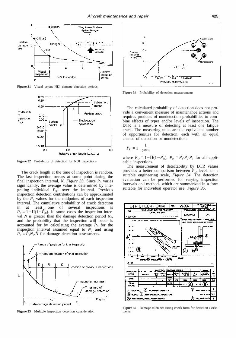
Use of Nondestructive Inspection (NDI) proceduressuch as ultrasonic or low frequency eddy current maysignificantly increase the damage detection period,Fig-ure 31. NDI procedures allow detection of smallersurface cracks than with visual inspection, and alsoallow subsurface crack detection. Therefore, an equalprobability of detecting damage can be achieved witha reduced inspection frequency. Damage detectionreliabilities have been established for different cracklengths in relation to the minimum detectable for typi-cal inspection techniques and structural configurations,Figure 32. TheseP3 curves are appropriately modifiedto account for visual detection of surface cracks andmultiple probe applications at different locations alongthe same crack during the same inspection of subsur-face cracks.
Figure 30 Effect of nondetection events on probability of detection
425Aircraft maintenance and repair
Figure 31 Visual versus NDI damage detection periods
Figure 32 Probability of detection for NDI inspections
The crack length at the time of inspection is random.The last inspection occurs at some point during thefinal inspection interval,N̄, Figure 33. SinceP3 variessignificantly, the average value is determined by inte-grating individual P3s over the interval. Previousinspection detection contributions can be approximatedby the P3 values for the midpoints of each inspectioninterval. The cumulative probability of crack detectionin at least one of several inspections isP3 = 12P(12P̂3i). In some cases the inspection inter-val N̄ is greater than the damage detection periodN0,and the probability that the inspection will occur isaccounted for by calculating the averageP̂3 for theinspection interval assumed equal toN0 and usingP3 = P̂3N0/N̄ for damage detection assessments.
Figure 33 Multiple inspection detection consideration
Figure 34 Probability of detection measurements
The calculated probability of detection does not pro-vide a convenient measure of maintenance actions andrequires products of nondetection probabilities to com-bine effects of types and/or levels of inspection. TheDTR is a measure of detecting at least one fatiguecrack. The measuring units are the equivalent numberof opportunities for detection, each with an equalchance of detection or nondetection:
PD = 121
2DTR
where PD = 12P(12Pdi), Pdi = P1·P2·P3 for all appli-cable inspections.
The measurement of detectability by DTR valuesprovides a better comparison betweenPD levels on asuitable engineering scale,Figure 34. The detectionevaluation can be performed for varying inspectionintervals and methods which are summarized in a formsuitable for individual operator use,Figure 35.
Figure 35 Damage-tolerance rating check form for detection assess-ments
426 U. G. Goranson
Inspection intervalsStructural inspection program planning involves frac-
ture mechanics evaluations of crack growth andresidual strength characteristics coupled to a damagedetection assessment. Residual strength and fatiguecrack growth evaluations are combined with service-based crack detection data to produce detectionreliability representing multiple type and intervals ofinspections in a fleet of airplanes subjected to explora-tory inspections. Such data give operators freedom toadjust quantitatively their maintenance program in anymanner that is desired as long as the required reliabilityof damage detection is preserved.
Traditional damage tolerance evaluations often con-centrate predominantly on the fracture mechanicsaspects and the inspection intervals are often simplychosen to reflect half of the damage growth periodfrom detectable to critical damage sizes. Such evalu-ations often fail to reflect the combined benefits ofvisual inspections performed during normal mainte-nance programs focused primarily on corrosion andaccidental damage sources. The value of cumulativecontributions of multiple inspections in a fleet of air-planes must also be recognized by accounting forsuch additional detection opportunities before the mostcritical change in one airplane reaches limit load dam-age containment capability. Several of these damagedetection considerations are discussed in the follow-ing sections.
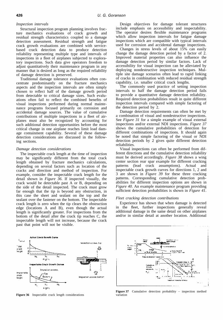
Damage detection considerationsThe inspectable crack length at the time of inspection
may be significantly different from the total cracklength obtained by fracture mechanics calculations,depending on several factors such as location of thecracks and direction and method of inspection. Forexample, consider the inspectable crack length for thedetail shown inFigure 36. If inspected visually, thecrack would be detectable past A or B, depending onthe side of the detail inspected. The crack must growfar enough that the tip is beyond any obstruction, inthis case the sheet and sealant on the top and thesealant over the fastener on the bottom. The inspectablecrack length is zero when the tip clears the obstructionedge (locations A and B), even though the actuallength is significantly greater. For inspections from thebottom of the detail after the crack tip reaches C, theinspectable length will not increase, because the crackpast that point will not be visible.
Figure 36 Inspectable crack length considerations
Design objectives for damage tolerant structuresinclude emphasis on accessibility and inspectability.The operator desires flexible maintenance programswhich allow inspection intervals for fatigue damageinspections which are compatible with typical intervalsused for corrosion and accidental damage inspections.
Changes in stress levels of about 15% can easilychange the damage detection period by a factor of 2.Improved material properties can also influence thedamage detection period by similar factors. Lack ofaccessibility for visual inspection can be alleviated bydeploying nondestructive inspection techniques. Mul-tiple site damage scenarios often lead to rapid linkingof cracks in combination with reduced residual strengthcapability, i.e. smaller critical crack lengths.
The commonly used practice of setting inspectionintervals to half the damage detection period failsto provide a quantitative damage detection reliability.Required detection probabilities result in quite differentinspection intervals compared with simple factoring ofthe detection period by 2.
Damage detection requirements can often be met bya combination of visual and nondestructive inspections.SeeFigure 31 for a simple example of visual externalinspections and/or external NDI inspections.Figure 37shows the cumulative probabilities of detection fordifferent combinations of inspections. It should againbe noted that simple factoring of the visual or NDIdetection periods by 2 gives quite different detectionreliabilities.
Visual inspections can often be performed from dif-ferent directions and the cumulative detection reliabilitymust be derived accordingly.Figure 38 shows a wingcenter section rear spar example for different crackingpatterns (lead crack assumptions). Actual andinspectable crack growth curves for directions 1, 2 and3 are shown inFigure 39 for these three crackingpatterns. Corresponding cumulative detection prob-abilities for different inspection options are shown inFigure 40. An example maintenance program providingsufficient detection probabilities is shown inFigure 41.
Fleet cracking detection contributionsExperience has shown that when damage is detected
in the fleet, further inspections generally revealadditional damage in the same detail on other airplanesand/or in similar detail at another location. Additional
Figure 37 Cumulative detection probability – inspection methodvariation

427Aircraft maintenance and repair
Figure 38 Wing spar chord cracking pattern examples
Figure 39 Spar chord crack growth curve examples – wingcenter section
Figure 40 Cumulative detection probability – cracking pattern
Figure 41 Cumulative detection probability – crackingpattern/variation inspection direction combinations
Figure 42 Multiple cracking in the fleet
damage in the fleet increases the probability ofdetecting at least one crack. The number of flightsbetween occurrences in the fleet of fatigue damage tothe same detail,DN, can be derived from actual fleetcracking statistics or from fleet usage and fatigue–lifedistribution. If the first damage is detectable atN1
flights, the second damage will reach the same levelof detectability atN1 + DN, and the third atN1 +2DN, Figure 42.
Each successive crack occurring during the damagedetection period,N0 for the first crack, has a reducedinterval for detection and a shorter crack length,Figure43. Taking this into consideration, the cumulative prob-ability of detection can be determined for each crackusing the same procedure. From this the probability ofcrack detection in the fleet is calculated, using a giveninspection method and frequency, as shown below:
P3 = 12 Pm
i = 1Pn
i = 1(12P̂3ij )
where P̂3ij is the probability of detection during theith inspection of thejth cracked airplane during thedamage detection periodN0; m is the number ofcracked airplanes; andn is the number of inspectionsperformed on thejth cracked airplane.
For convenience an equivalent constant probabilityof detection for each inspection can be defined by
P̄3 = 12(12P̂3)N̄/N0
Figure 43 Multiple fleet cracking contributions to damage detection

428 U. G. Goranson
Considering all levels of inspection in the fleet (A,B, C and D), the cumulative probability of damagedetection is given by
PD = 12P(12Pdi)
where PD = P1·P2·P3, i = applicable inspections.
CONTINUING AIRWORTHINESS INITIATIVES
Continuing airworthiness concerns for aging jet trans-ports has received attention over the last 15 years.Supplemental structural inspection programs weredeveloped in the late 1970s to address fatigue crackingdetection in airplanes designed to the fail-safe prin-ciples. These evaluations were performed in accordancewith updated damage tolerance regulations to reflect thestate-of-the-art in residual strength and crack growthanalyses based on fracture mechanics principles. Dam-age at multiple sites was also addressed in terms ofdependent damage size distributions in relation toassumed lead cracks in different structural members.Structural audits were performed in the mid 1980s toascertain whether these supplemental inspection pro-grams addressed independent multiple site damage insimilar structural details subjected to similar stresses.
Boeing initiated aging fleet surveys by engineeringteams in 1986 to gain a better understanding of thecondition of structures and systems and to observe theeffectiveness of corrosion prevention features and othercorrosion control actions taken by the operators. Boe-ing, like other manufacturers, continually reviewsreported service data and other first-hand informationfrom customer airlines in order to promote safe andeconomic operation of the worldwide fleet. These sur-veys were primarily prompted by the projected upwardtrend in airplane age toward and beyond original designservice objectives.
Extensive industry actions were initiated in 1988 toaddress aging fleet airworthiness concerns prompted bythe explosive decompression of a 737 over Hawaii.Model-specific Structures Working Groups have dem-onstrated a cooperative determination over the last fiveyear period to make the right things happen withinand across models and throughout the industry. Theachievements have been impressive in theaccomplishing of results in five original tasks charteredby the Airworthiness Assurance Task Force, nowknown as the Airworthiness Assurance Working Group,Figure 44.
Figure 44 Continued airworthiness industry initiatives
Figure 45 In-service problem actions
Service bulletin reviews and mandatory inspectionsContinuing airworthiness of jet transport structures
designed to the fail-safe principles has traditionallybeen ensured by inspection programs. In the eventof known, specific fatigue cracking and/or corrosionproblems, that if not detected and repaired had thepotential to cause a significant degradation in airworth-iness, the normal practice in the past was to introducea service bulletin,Figure 45.
The net result of this process was to carry outinspections of all affected airplanes until damage wasdetected and then to perform the repair. Thus, continu-ing structural airworthiness was totally dependent onrepetitive inspections. Aging airplane concernsprompted reassessment of the viability of indefiniterepetitive inspections.
Aging fleet service bulletin summary documentswere released in 1989 for each model formalizingStructures Working Group (SWG) recommendationsfor mandatory modifications or inspections,Figure 46.
It is important to note that cumulative service experi-ence is incorporated in the design and reflected by lessinspection/modification for later production units. Inturn, these service experiences are incorporated in newmodels, often with orders of magnitude reduction inlater modification efforts.
Corrosion prevention and control programsWhile corrosion has always been recognized as a
major factor in airplane maintenance, each airline hasaddressed it differently according to its operatingenvironment and perceived needs. Manufacturers havepublished corrosion prevention manuals and guidelines
Figure 46 Mandatory service bulletin modification example for 727horizontal stabilizer front spar center section with stress corrosionproblems

429Aircraft maintenance and repair
to assist the operators, but until now there have neverbeen mandatory corrosion control programs.
It became apparent that without effective corrosioncontrol programs, the frequency and severity of cor-rosion were increasing with airplane age and, as such,corrosion was more likely to be associated with otherforms of damage such as fatigue cracking. This, ifallowed to continue, could lead to an unacceptabledegradation of structural integrity, and in an extremeinstance, the loss of an airplane.
The working groups have recognized the need for auniversal baseline minimum corrosion control programfor all airplanes to prevent corrosion from affectingairworthiness. Maximum commonality of approachwithin and between each manufacturer to ensure con-sistent and effective procedures throughout the worldhas been a key objective for the working groups. Theprogram requirements apply to all airplanes that havereached or exceeded the specified implementation agethreshold for each airplane area. The specific intervalsand thresholds vary between models, but all programsfollow the same basic philosophy.
The corrosion control and prevention program pro-vides structural access and inspections of internalstructure and structure hidden by fairings in adisciplined and consistent manner. While many oper-ators may already have covered these areas inexisting maintenance programs, the net effect hasbeen an increased awareness for the value of Cor-rosion Prevention and Control Programs (CPCPs),Figure 47.
There is general agreement in the airplane industrythat corrosion prevention and control procedures areneeded on all current in-production airplanes and forfuture generations of airplanes.
Supplemental fatigue inspection programsSupplemental structural inspection documents were
released between 1979 and 1983 for all aging Boeingjet transport models. Their purpose was to ensurecontinued operation of the aging fleet by timely detec-tion of new fatigue damage locations. These documentshave been updated on a regular basis to reflect serviceexperience and operator inputs. In the light of currentaging fleet concerns, these inspection programs wereto ensure adequate protection of the aging fleet. Themajor focus of these reviews was:
Figure 47 727 corrosion control program – example
I adequacy of the present fleet leader sampling;I inclusion/deletion of principal structural elements.
Revisions to 707, 727, 737 and 747 SSIDs includedchanges to approximately 10 significant structural itemsfor each model. Some PSEs were not included in theoriginal SSID on the basis that damage would beobvious before safety was affected. A review of thoseitems resulted in adding several items to the SSID,primarily some hidden wing structures previouslydeleted on the basis of fuel leaks to signify fatiguedamage.
Thin gauge fuselage structure was not included inthe initial SSIDs on the basis of test and serviceevidence that skin cracks would turn at frame locationsand result in a safe decompression. Consideration ofaging fleet damage in adjacent bays prompted coverageof thin gauge fuselage structure, 1.4 mm thick or lessfor models 727 and 737. The 747 fuselage skins werealready included in the initial SSID because ofthicker gauges.
Widespread fatigue damageThe present rules for airplane structural design have
evolved from successful experience and lessons learnedin service. As opposed to earlier commercial airplanes,the first generation of jet transports have not becometechnically obsolete before portions of the worldwidefleet have reached and exceeded original design serviceobjectives. Dependent damage at multiple sites wasrecognized in revised damage tolerance regulations inthe late 1970s. Independent damage in similar detailssubjected to similar stresses has long been recognizedas a potential continuing airworthiness problem. Fusel-age structure is typically more susceptible to WFDbecause of numerous similar details subjected to press-ure cycle loads with moderate flight-by-flight vari-ations.
An international task group was chartered in 1990composed of manufacturers and operators to investigateand propose appropriate actions to address WFD con-cerns by timely discovery of any aging fleet problems.The Structural Audit and Evaluation Task Group(SAETG) performed an extensive data collection andanalysis activity to determine candidate options thathave applicability to the identified concerns. While allthe adopted SAETG options are valid to some extentin predicting the onset and location of multiple sitedamage and multiple element damage, none of theoptions provides foolproof safeguards. Ultimately con-scientious and reliable inspections of the airplane struc-ture are the key to confidence in ensuring continuingairworthiness.
Structural repair assessmentsInevitably airplanes accumulate repairs. For each
model, Structural Repair Manuals (SRMs) assist theoperator in ensuring that typical repair action maintainsthe airframe structural integrity. Other larger repairsare handled by individually prepared and approvedengineering drawings. Traditionally, these repairs haveprimarily focused on static strength and fail-safeaspects of the structure after repair, with commonsenseattention to durability considerations. For several years,however, there has been an additional emphasis on theneed for structures to be damage tolerant. Achieving
430 U. G. Goranson
damage tolerance demands knowledge of potentiallycritical structural elements, an understanding of damagegrowth and critical size, and an inspection program toensure timely detection.
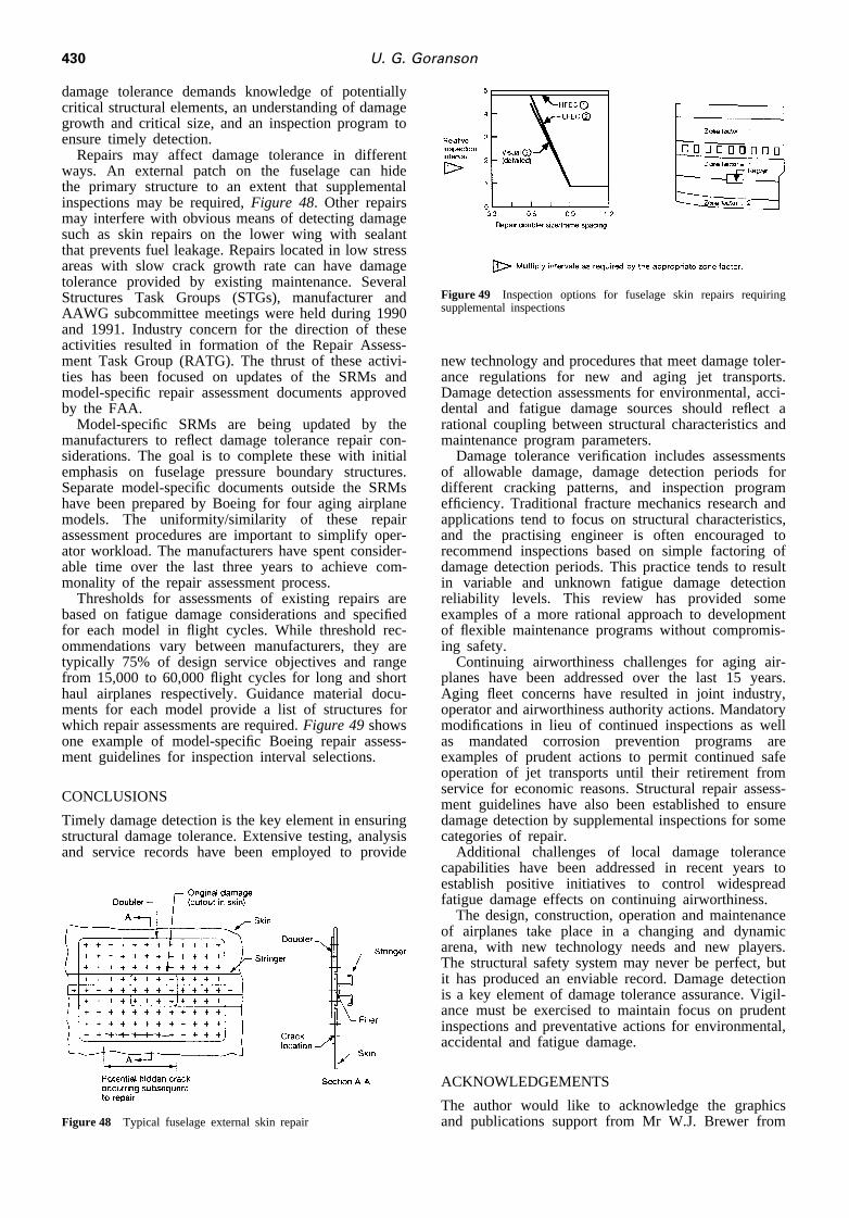
Repairs may affect damage tolerance in differentways. An external patch on the fuselage can hidethe primary structure to an extent that supplementalinspections may be required,Figure 48. Other repairsmay interfere with obvious means of detecting damagesuch as skin repairs on the lower wing with sealantthat prevents fuel leakage. Repairs located in low stressareas with slow crack growth rate can have damagetolerance provided by existing maintenance. SeveralStructures Task Groups (STGs), manufacturer andAAWG subcommittee meetings were held during 1990and 1991. Industry concern for the direction of theseactivities resulted in formation of the Repair Assess-ment Task Group (RATG). The thrust of these activi-ties has been focused on updates of the SRMs andmodel-specific repair assessment documents approvedby the FAA.
Model-specific SRMs are being updated by themanufacturers to reflect damage tolerance repair con-siderations. The goal is to complete these with initialemphasis on fuselage pressure boundary structures.Separate model-specific documents outside the SRMshave been prepared by Boeing for four aging airplanemodels. The uniformity/similarity of these repairassessment procedures are important to simplify oper-ator workload. The manufacturers have spent consider-able time over the last three years to achieve com-monality of the repair assessment process.
Thresholds for assessments of existing repairs arebased on fatigue damage considerations and specifiedfor each model in flight cycles. While threshold rec-ommendations vary between manufacturers, they aretypically 75% of design service objectives and rangefrom 15,000 to 60,000 flight cycles for long and shorthaul airplanes respectively. Guidance material docu-ments for each model provide a list of structures forwhich repair assessments are required.Figure 49showsone example of model-specific Boeing repair assess-ment guidelines for inspection interval selections.
CONCLUSIONS
Timely damage detection is the key element in ensuringstructural damage tolerance. Extensive testing, analysisand service records have been employed to provide
Figure 48 Typical fuselage external skin repair
Figure 49 Inspection options for fuselage skin repairs requiringsupplemental inspections
new technology and procedures that meet damage toler-ance regulations for new and aging jet transports.Damage detection assessments for environmental, acci-dental and fatigue damage sources should reflect arational coupling between structural characteristics andmaintenance program parameters.
Damage tolerance verification includes assessmentsof allowable damage, damage detection periods fordifferent cracking patterns, and inspection programefficiency. Traditional fracture mechanics research andapplications tend to focus on structural characteristics,and the practising engineer is often encouraged torecommend inspections based on simple factoring ofdamage detection periods. This practice tends to resultin variable and unknown fatigue damage detectionreliability levels. This review has provided someexamples of a more rational approach to developmentof flexible maintenance programs without compromis-ing safety.
Continuing airworthiness challenges for aging air-planes have been addressed over the last 15 years.Aging fleet concerns have resulted in joint industry,operator and airworthiness authority actions. Mandatorymodifications in lieu of continued inspections as wellas mandated corrosion prevention programs areexamples of prudent actions to permit continued safeoperation of jet transports until their retirement fromservice for economic reasons. Structural repair assess-ment guidelines have also been established to ensuredamage detection by supplemental inspections for somecategories of repair.
Additional challenges of local damage tolerancecapabilities have been addressed in recent years toestablish positive initiatives to control widespreadfatigue damage effects on continuing airworthiness.
The design, construction, operation and maintenanceof airplanes take place in a changing and dynamicarena, with new technology needs and new players.The structural safety system may never be perfect, butit has produced an enviable record. Damage detectionis a key element of damage tolerance assurance. Vigil-ance must be exercised to maintain focus on prudentinspections and preventative actions for environmental,accidental and fatigue damage.
ACKNOWLEDGEMENTS
The author would like to acknowledge the graphicsand publications support from Mr W.J. Brewer from

431Aircraft maintenance and repair
the Structures Engineering organization of BoeingCommercial Airplane Group, and Mr Floyd Stewartand staff from Boeing Information and Support Ser-vices, Graphic and Media Design Resources.
REFERENCES
1 Whittaker, I. C. and Besuner, P. M., A reliability analysisapproach to fatigue life variability of aircraft structures. AirForce Materials Laboratory Technical Report AFML-TR-69-65,April 1969.
2 Whittaker, I. C., Development of titanium and steel fatiguevariability model for application of reliability analysis approachto aircraft structures. Air Force Materials Laboratory TechnicalReport AFML-TR-72-236, October 1972.
3 Broek, D., Damage tolerance in practice, AGARD Lecture SeriesNo. 97 on Fatigue Mechanics in Practice. Delft, The Netherlands,October 1978.
4 Craig, L. E. and Goranson, U. G., Airworthiness assessment ofBoeing jet transport structures. 10th Symposium of the Inter-national Committee on Aeronautical Fatigue (ICAF), Brussels,Belgium, May 1979.
5 Goranson, U. G., Hall, J., Maclin, J. R. and Watanabe, R.T., Long life damage tolerant jet transport structures. ASTMSymposium on Design of Fatigue and Fracture Resistant Struc-tures, November 10–11, 1980.
6 Galda, K. H., Maintenance system by means of damage toleranceprinciple. 13th Symposium of the International Committee onFatigue (ICAF), Pisa, Italy, May 22–24, 1985.
7 Broek, D.Elementary Engineering Fracture Mechanics, 4th edn.Martinus Nijhoff, 1987.
8 Miller, M., Luthra, V. K. and Goranson, U. G., Fatigue crackgrowth characterization of jet transport structures. 14th Sym-posium of the International Committee on Aeronautical Fatigue(ICAF), Ottawa, Canada, June 8–12, 1987.
9 Swift, T., Damage tolerance in pressurized fuselages. 11th Plan-tema Memorial Lecture, 14th Symposium of the InternationalCommittee on Aeronautical Fatigue (ICAF), Ottawa, Canada,June 8–12, 1987.
10 Goranson, U. G. and Miller, M., Aging jet transport structuralevaluation programs. 15th Symposium of the International Com-mittee on Aeronautical Fatigue (ICAF), Jerusalem, Israel, June21–23, 1989.
11 Whittaker, I. C., Miller, M. and Goranson, U. G., Durabilityand damage tolerance evaluations of jet transport structures. 5thInternational Conference on Structural Safety and Reliability(ICOSSAR), San Francisco, CA, August 1989.
12 Sampath, S. G. and Broek, D., The prospect of detecting anddealing with widespread fatigue damage: threshold for inspectingMSD susceptible lap spices. International Conference on AircraftDamage Assessment and Repair, Melbourne, Australia, August26–28, 1991.
13 Whittaker, I. C., Stilwell, P. B. and Sizemore, D. R., Fleetfatigue cracking threshold prediction. 16th Symposium of theInternational Committee on Aeronautical Fatigue (ICAF), Tokyo,Japan, May 20–24, 1991.
14 Schijve, J., Multiple site fatigue damage of riveted joints. Pro-ceedings of the International Workshop on Structural Integrityof Aging Airplanes, Atlanta, GA, March 31–April 2, 1992.
15 Schmidt, H. J. and Brandecker, B., Results of the AAWGindustry committee on widespread fatigue damage. Proceedingsof the International Workshop on Structural Integrity of AgingAirplanes, Atlanta, GA, March 31–April 2, 1992.
16 Swift, T., Unarrested fast fracture. Proceedings of the Inter-national Workshop on Structural Integrity of Aging Airplanes,Atlanta, GA, March 31–April 2, 1992.
17 Broek, D., The effects of multi-site-damage on the arrest capa-bility of aircraft fuselage structures. FractuREsearch TR9302,June 1993.
18 Goranson, U. G., Damage tolerance facts and fiction. 17thSymposium of the International Committee on AeronauticalFatigue, Engineering Material Advisory Service Ltd., 17-1(1993–1996).
19 Thomson, D., Hoadley, D. and McHatton, J., Load tests of flatand curved panels with multiple cracks. Foster–Miller DraftFinal Report to the FAA Center, September 1993.
20 Bigelow, C. A. and Tan, P. W., An integrated methodologyfor assessing widespread fatigue damage in aircraft structures.Proceedings of the FAA–NASA 6th International Conference onthe Continued Airworthiness of Aircraft Structures, Atlantic City,NJ, June 27–28, 1995, pp. 121–138.
21 deWit, R., Fields, R. J., Low III, S. R., Harne, D. E. andFoecke, T., Fracture testing of large-scale thin-sheet aluminumalloy. NIST Report 5661, Prepared for FAA, May 1995.
22 Goranson, U. G., Aging aircraft airworthiness initiatives.TheJapan Society of Mechanical Engineering Journal, 1995, 98-915, 101.
23 Gruber, M. L., Mazur, C. J., Wilkins, K. E. and Worden, R.E., Investigation of fuselage structure subject to widespreadfatigue damage. Final Report to the FAA, DOT/FAA/AR-95/47,October 1995.
24 Harris, C. E., Starnes Jr., J. H. and Newman Jr., J. C., Develop-ment of advanced structural analysis methodologies for pre-dicting widespread fatigue damage in aircraft structures. Proceed-ings of the FAA–NASA 6th International Conference on theContinued Airworthiness of Aircraft Structures, Atlantic City,NJ, June 27–28, 1995, pp. 139–164.
25 Newman Jr., J. C. and Dawicke, D. S., Fracture analysis ofstiffened panels under biaxial loading with widespread cracking.NASA Report TM 110197, November 1995.
26 Wang, L., Brust, F. W. and Atluri, S. N., Computational predic-tions of the NIST multiple site damage experimental results.FAA Center of Excellence Report, Georgia Institute of Tech-nology, August 1995.
27 McGuire, J. F. and Varanasi, S. R., Boeing structural design andtechnology improvements.The Boeing Airliner, April–June 1996.
28 Gruber, M. L., Wilkins, K. E. and Worden, R. E., Investigationof fuselage structure subject to widespread fatigue damage.Proceedings of the FAA–NASA Symposium on Continued Air-worthiness of Aircraft Structures, Atlanta, GA, August 1996.
29 Whittaker, I. C. and Chen, H. C., Widespread fatigue damagethreshold estimates. Proceedings of the FAA–NASA Symposiumon Continued Airworthiness of Aircraft Structures, Atlanta, GA,August 1996.