Embed Size (px)
Citation preview
AD-A238 6861111 II iii Ilf l l II "..
R91-917992-2
FATIGUE AND FRACTURE OFINTERMETALLIC ALLOYS
Prepared by
C. V. CooperI. R. P. InoueA. F. GiameiL. H. Favrow
ANNUAL REPORT
Contract F49620-89-C-0047
for
Air Force Office of Scientific ResearchBoiling Air Force BaseWashington, DC 20332
May 22, 1991
91-05869II 1111111li! 1111111I
UNITEDTECHNOLOGIESRESEARCHCENTER

DISCLAIMER NOTICE
THIS DOCUMENT IS BEST
QUALITY AVAILABLE. THE COPY
FURNISHED TO DTIC CONTAINED
A SIGNIFICANT NUMBER OF
COLOR PAGES WHICH DO NOT
REPRODUCE LEGIBLY ON BLACK
AND WHITE MICROFICHE.

REPORT DOCUMENTATION PAGE For A 0704-78
a..06'( :ftort-q Du'l" 10 r*-' caecOrof of ntormatom % est'-Ateq* 4.@'&qe Del. ~' .wc ie c C~lq ~eC 'o .e.. n ,c.on earernq c."t "q Istu volatp'w q *Ad 'n.ta~f.nq tP'@ data move" and comOff,1q Jnd 'Pe.' -e ',@ cr, :' -1-av' - d con'-n ri 0?'' ",I~ 0.raen @t-af. ,, r, t ~ Aa t I..
C 10r ? i motw atoon ,'uCIA9n SU99 Voe" -0, -S ,,rar. 48S"t"o, e0800-1 ell e (ei Z.rft-o0,1 0 ator 0 o.at'oe', ad *-, 0 0" i f"'0a.-i .0qheay swo 1204 A"'0qIOr JA 22103O2 And to P' "e -eI MA-A,, '-T" ,ro Sqe *foe-.o'X A@ OW I e,o Q'Cd..7044U) 1V~sA'nqtoA -C ^"3J
1. AGENCY USE ONLY (Ledfve 0dnk) 2. REORT DATE 3. REPORT TYPE AND DATES COVEREDP30 /9 1 nnual. - 1 'qO - 3'31,.91
4. TITLE AND SUBTITLE S. FUNDING NUMBERS
Fat izue and Fracture of Inte rmetal I ic A!loys .92---OD;6, AUTHOR(S)
C. V. Cooper, H. R. P. Inoue,A. F. Giamei, and L. H. Favrow'
7. PERFORMING ORGANIZATION NAME(S) AND ADDRESS(ES) 8. PERFORMING ORGANIZATIONREPORT NUMBER
United Tech. Res. Ctr. ,niv.. of Illinois400 Main Street and at Urbana-Champaign
E. Hartford, CT 06108 Urbana, Illinois 61801 R91-917992-2
9 SPONSORING MONITORING AGENCY NAME(S) AND ADORESS(ES) 10. SPONSORING MONITORINGAGENCY REPORT NUMBER
Air Force Office of Scientific Research
Boiling Air Force BaseWashington, DC 20332 1
It. SUPPLEMENTARY NOTES
112a. DISTRIBUTION I AVAILABIUJTY STATEMENT 12b. DISTRIBUTION CODE
Unl imitedI
"SThe crystal structure of f1c-based ordered A1311 has been modified from the DO22-tYpeto the Li 2-type structure by the addition of 7.5 at.% Fe. This alloy is essentially singlephase after homogenization at 1 1000C at 100 h with a very small volume fraction ofprecipitates which have formed heterogeneously along dislocations. In the as-arc-castcondition, a high density of small precipitates occurred heterogeneously andhomogeneously, in addition to the formation of a large sized, faulted second phase. Inthis case, precipitates which formed heterogeneously along dislocations are larger insize when compared to ones which formed in the homogenized condition.Precipitates which formed homogeneously in Li 2 grains were in the form of thinplates. Detailed crystal- and micro-structural observations of plate-shaped precipitateshave revealed their precipitation on planes parallel to (001) LI 2. These precipitateshave been determined to possess an ordered tetragonal structure which is composedof 6 fcc unit cells consisting of 4 titanium and 20 aluminum atoms. p )________
14. SUIIJECT TERMS 15. NUMBER OF PAGESDislocation cross slip, upper and lower yield points, ductile-to-britl transilorterrperaturp P- oitinn, !,ornl~er'ization tweat treatment, lour-point flexure, 16. PRICE coDE
monotoniccompression, L12 arid D022 crystal structures, second phases.11. SECURIJTY CLASSIFICATIION 13. SECUR11TY CLASSIFIC.ATION 19 SECURIT CJ.ASSIPICATION 20. LIMITATION OF ABSTRACT
OF REPORT Of THIS PAGE OP ABSTRACT
UnclssiiedI Unclassified !'nc1asifiPd ___1ne _____
'YSN 754O-O1.280-5'00 Sta'dard ;0'r" "98 Re,
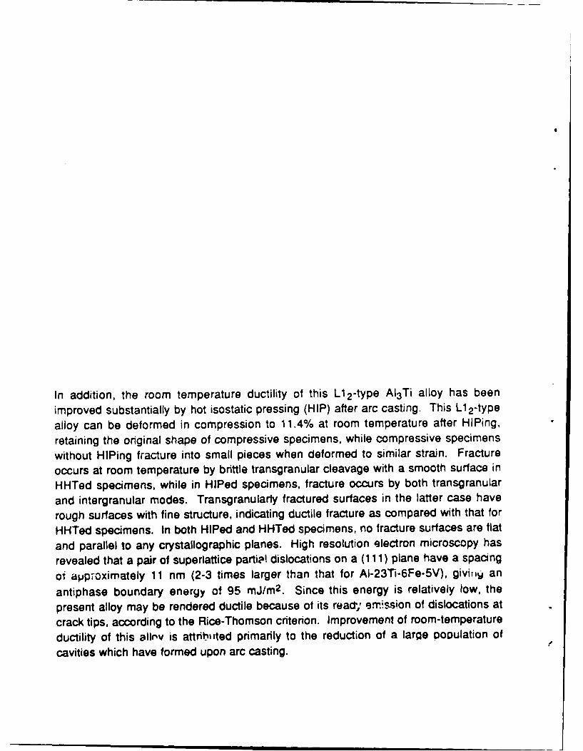
In addition, the room temperature ductility of this L1 2-type Al 3Ti alloy has been
improved substantially by hot isostatic pressing (HIP) after arc casting. This L1 2-type
alloy can be deformed in compression to 11.4% at room temperature after HIPing,
retaining the original shape of compressive specimens, while compressive specimens
without HIPing fracture into small pieces when deformed to similar strain. Fracture
occurs at room temperature by brittle transgranular cleavage with a smooth surface in
HHTed specimens, while in HIPed specimens, fracture occurs by both transgranular
and intergranular modes. Transgranularly fractured surfaces in the latter case have
rough surfaces with fine structure, indicating ductile fracture as compared with that for
HHTed specimens. In both HIPed and HHTed specimens, no fracture surfaces are flat
and parallel to any crystallographic planes. High resolution electron microscopy has
revealed that a pair of superlattice partip, dislocations on a (111) plane have a spacing
of approximately 11 nm (2-3 times larger than that for AI-23Ti-6Fe-5V), givit, an
antiphase boundary energy of 95 mJ/m 2 . Since this energy is relatively low, the
present alloy may be rendered ductile because of its read'; erm'smion of dislocations at
crack tips, according to the Rice-Thomson criterion. Improvement of room-temperature
ductility of this allrv is attributed primarily to the reduction of a large DoDulation of
cavities which have formed upon arc casting.

R91-91 7992-2
Fatigue and Fracture ofIntermetallic Alloys
ANNUAL REPORT
Contract F49620-89-C-0047
REPORTED BY: v --C. V. Cooper
H. R. P. Inoue
-7 ' ". . .,'._ h -
A. F. Giamei
4
L. H. Favrow
APPROVED BY: 7 (C ' (..,.., - ,.M. A. DeCrescenteManager of Mfg. Tech.and Process Research
DATE: 5/22/91

TABLE OF CONTENTS
1. INTRODUCTION .................................... 11 .1 O v e rv ie w ................................................................................... 11.2 Review of the Literature .......................................................... 3
1.2.1 Phase Equilibria and Microstructural Studies ........ 31.2.2 Deformation Studies ................................................... 5
2. EXPERIMENTAL PROCEDURES......................... 72 .1 A llo y C a stin g ............................................................................ 72.2 Specimen Preparation and Heat Treatment ............ 92 .3 M ic ro sc o p y .............................................................................. 1 02 .4 M echanical B e havio r ........................................................... 11
3. RESULTS AND DISCUSSION ....................... 123.1 Microscopic Observations and Crystallographic .......... 12
Orientation of Second Phase Precipitates3 .1.1 M icrostructures .......................................................... 123.1.2 Crystal Structure of Plate-Shaped Precipitates... 13
3.2 Comparison of Fracture Properties between ....... 15HIP and HHT Conditions
3 .2 .1 M icrostructures .......................................................... 153.2.2 Temperature Dependence of Yield Stress ........... 153.2.3 Fracture Morphologies ............................................. 163.2.4 Dislocation Structure ................................................ 17
4. SUMMARY AND CONCLUSIONS ............................................. 19
5. WORK IN PROGRESS .................................................................. 215.1 Tensile and Fatigue Data ................................................. 215.2 The Effects of Powder Size ............................................... 215.3 The Effects of Iron Content ............................................... 225.4 Niobium Alloy Studies ....................................................... 22
6 . R E F E R E N C E S .............................................................................. 2 3
FIGURES 1 - 15
R91-917992-2
1. INTRODUCTION
1.1 Overview
Future generations of aircraft gas turbine engines will, most likely, utilize
hol-sectiuit niria;s based on systems other than the now-mature nickel-base
superalloys. The identification of new systems has been motivated by the quest
for higher combustion temperatures to satisfy the need for greater thrust-to-
weight ratios and higher operating efficiencies. Among the potential systems is
the broad class of materials known as intermetallics. Indeed, much research
and development has gone into the study of intermetallic compounds based on
the titanium-aluminum system, often with the focus on alloy development
through ternary and quaternary additions as well as thermomechanicalprocessing.
Three ordered compounds based on this binary system have beer,investigated to varying degrees: Ti3AI (eC2 :alpha-2), TiAI (y:gamma), and AI3 Ti
(rl:eta). Because of the increasing tendency to form oxidation-protective
alumina films and its inherently low density (3.3 g/cm3), AI 3Ti has held particularattraction. As with the y phase, a major difficulty with the T1 phase is inherent
lack of ductility in the binary composition. Despite its intrinsic oxidation
resistance, AI3 Ti, which in the binary form exhibits a DO22 (ordered tetragonal)crystal structure, has remained relatively understudied. The DO19 (cL2), the Ll0
(y), the DO 22 (TI), and the well known L1 2 (T) phases are all closed-packed and
are related by variations in stacking and/or chemistry of the close-packed
planes.
Through the addition of certain ternary transition metals, including iron,copper, or nickel, a phase transition from ri to the ordered cubic, L1 2 can be
induced. Being a crystal structure with higher symmetry over the DO 22, the L12
possesses potential advantages in mechanical behavior over the ordered
tetragonal structure due to the increase in the number of active slip systems and
the satisfaction of the well known Von Mises criterion for strain compatibility in
polycrystals (Ref. 1).
1

R91-917992-2
Nonetheless, much research remains to be accomplished in the areas of
understanding the exact mechanisms through which the L1 2 structure car, be
rendered increasingly ductile and the nature and location of the ductile-to-brittle
transition phenomenor: furthermore, the entire areas of tensile arid cyclic
deformation remain virtually uninvestigated to date, at least in the open
literature.
The attainment of the high symmetry, L1 2 structure is, of course, no
guarantee that the alloy exhibits reasonable ductility. While the primary
deformation mechanism in this structure, as discussed in greater detail below, is
slip along octahedral planes, the cross slip of screw dislocations ii..o cube
planes creates sessile portions, which can lead to reduc'ion in the tensile
elongation to failure. High Peierls stresses may exist for certain dislocation
dissociations, especially where fault energies are high (Refs. 2-8). Grain
refinement, for example can lead to increases in flow stress, such that the
cleavage stress is lower than the tensile yield stress. However, the cubic
symmetry and close packed nature of the L1 2 lattice offer the opportunity for
useful ductility.
The intermetallic compounds of most interest show some solid solubility
(i.e. they are not "line compounds") and are of high symmetry. The former
condition pre-empts the possibility of forming small amounts of undesired
equilibrium phases, while the latter condition maximizes the opportunities for
multiple slip systems and the achievement of adequate low temperature fracture
toughness. It turns out that the AI3X compounds, where X is Ti or Nb, are DO 2 2
compounds. This structure is closely related to Li 2 , which is the crystal
structure of the famous gamma prime phase. Even gamma prime has limited
ductility under certain circumstances, but it is well understood and of great
engineering significance. In addition, when AI 3Ti is alloyed with iron (or
copper), the resultant Li 2 structure has a finite phase field width.
2

R91-917992-2
1.2 Review of the Literature
1.2.1 Phase Equilibria and Microstructural Studies
Because of the extreme lack of tensile ductility and fracture toughness at
room temperature for AI3Ti, most recent studies, as noted above, have focused
on alloying additions to induce the transformation from DO 2 2 to L12. The first to
report this phase transformation were Raman and Schubert (Ref. 9), who
accomplished the transition by dilute alloying additions of copper, nickel, or zinc
in substitution for aluminum. Similar phase transformation have been noted
more recently by Seibold (Ref. 10) through substitutions of iron for aluminum.
While required concentrations of the selected ternary additions vary, the typical
range lies from five to fifteen atomic percent.
Many recent studies have concentrated on the specific effects of alloying
additions and rapid solidification processing on the resulting microstructures
and phase fields. For example, Huang, Hall and Giogliotti (Ref. 11) investigated
rapidly solidified Al-Ni-Ti in the atomic ratio of 65:10:25 and found
predominantly but not exclusively cubic L12 phase. Powers, Wert, and Turner
(Ref. 12) considered nickel-modified Al3 Ti, prepared by the non-consumable
arc melting technique, in the atomic ratio of 67AI:8Ni:25Ti. Non-single-phase
structures consisting predominantly of L12 were observed. Also, features
exhibiting stacking-fault-like contrast were observed on {001} planes and were
determined to be intrinsic stacking faults, which resulted from the dissociation of
a0 <110>{001} dislocations. These faults were determined to be sessile in
nature and did not participate in the deformation process.
Tarnacki and Kim (Ref. 13) have examined arc-melted and rapidlysolidified -t phase which had been modified by copper additions leading to
AI5CuTi 2 , or by small amounts of boron or manganese. Rapid solidification by
melt-spinning was found to refine the microstructure significantly and increase
the microhardness slightly compared to the as-cast alloy. The as-castmicrostructure of the copper ternary was two-phase, with the primary phase
described as having the "nominal composition" and the dispersed second
phase being globules with sizes ranging from 3-20 pm. X-ray diffraction
3

R91-917992-2
analysis verified the L12 crystal structure for both the as-cast and rapidly
solidified forms. In addition, fine, second-phase particles on the order of 100
nm which were Cu-rich were resolved by TEM. While mechanical property
determinations were not the focus of Tarnacki and Kim's study, the addition of
copper and the achievement of the L12 were observed to result in no
improvements in ductility over the binary AI3 Ti.
Mazdiyasni et al. (Ref. 14) examined the phase equilibria of iron, nickel,
and copper-modified AI3 Ti prepared by vacuum arc melting. The resulting
phase-field width was determined using x ray diffraction of powder samples
following homogenization and quenching from 800 and 1200°C. Single-phaset was found for all three ternary systems for the 1200°C isotherm. At 800"C, the
width of the single-phase field was reduced for the iron and nickel ternary
systems; the phase boundary was not determinable for the nickel ternary due to
the nucleation of a fine, second-phase precipitate. These authors found that the
Li 2 phase was stable to at least 1 200'C in all three alloy systems.
However, Tarnacki and Kim (Ref. 15) failed to produce single-phase r in
the Al-Ni-Ti ternary system despite a post-arc-melting homogenization heat
treatment for 96 hr at 1100C in the A167 Ni 8 Ti 25 ternary system.
A very exciting result from this laboratory (UTRC) is the achievement ofphase-pure t in the iron ternary system. As is to be discussed further in section
3.0, single phase Li 2 with only isolated carbides, believed to be the result of
impurities introduced with the iron, has boen produced recently by the hot-
pressing of prealloyed, ball-mill-attrited powders. This has been achieved
despite the well known difficulties associated with establishing equilibrium in
peritectic systems.
To date, little information is available on the DO 22 system, AI3 Nb. While
the likelihood of transforming this system to phase-pure L12 remains unclear,
unpublished reports indicate that additions of chromium, yttrium, and tungsten
lead to a stable, oxidation-resistant, fracture-tough alloy. Furthermore, it should
be possible to transform iron- and titanium-modified AI 3 Nb to the L12 crystal
structure through alloying, by analogy to AI3Ti.
4
R91-917992-2
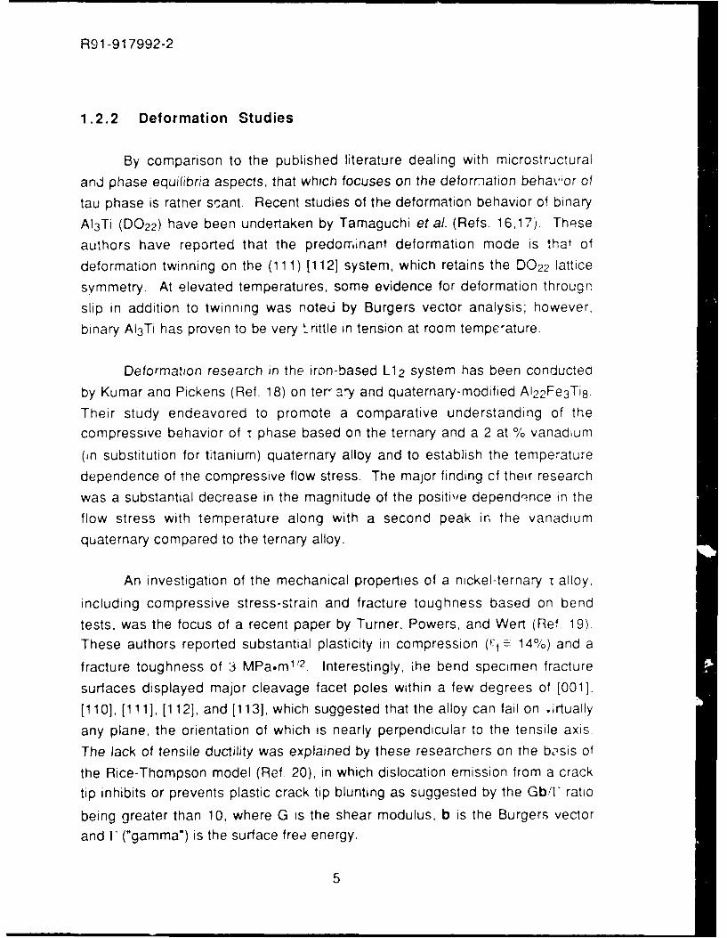
1.2.2 Deformation Studies
By comparison to the published literature dealing with microstructural
and phase equilibria aspects, that which focuses on the deformation behavor of
tau phase is rather scant. Recent studies of the deformation behavior of binary
AI 3Ti (DO 22 ) have been undertaken by Tamaguchi et al. (Refs. 16,17). These
authors have reported that the predominant deformation mode is that of
deformation twinning on the (111) [112] system, which retains the DO 22 lattice
symmetry. At elevated temperatures, some evidence for deformation througn
slip in addition to twinning was noted by Burgers vector analysis; however,
binary AI3 Ti has proven to be very brittle in tension at room temperature.
Deformation research in the iron-based L12 system has been conducted
by Kumar ana Pickens (Ref. 18) on ter, ary and quaternary-modified AI 22 Fe 3 Ti 8.
Their study endeavored to promote a comparative understanding of the
compressive behavior of T phase based on the ternary and a 2 at.% vanadium
(in substitution for titanium) quaternary alloy and to establish the temperature
dependence of tme compressive flow stress. The major finding cf their research
was a substantial decrease in the magnitude of the positive dependence in the
flow stress with temperature along with a second peak in the vanadium
quaternary compared to the ternary alloy.
An investigation of the mechanical properties of a nickel-ternary i alloy,
including compressive stress-strain and fracture toughness based on bend
tests, was the focus of a recent paper by Turner, Powers, and Wert (Ref. 19)
These authors reported substantial plasticity in compression (1f : 14%) and a
fracture toughness of 3 MPa.m 1' 2 . Interestingly, ihe bend specimen fracture
surfaces displayed major cleavage facet poles within a few degrees of [0013,
[110], [111], [112], and [113], which suggested that the alloy can fail on irtually
any plane, the orientation of which is nearly perpendicular to the tensile axis.
The lack of tensile ductility was explained by these researchers on the basis of
the Rice-Thompson model (Ref 20), in which dislocation emission from a crack
tip inhibits or prevents plastic crack tip blunting as suggested by the Gb/F ratio
being greater than 10, where G is the shear modulus, b is the Burgers vector
and F ("gamma") is the surface free energy.
5

R91-917992-2
Porosity and the presence of a more brittle second phase are additionalproblems which complicate the measurement of the tensile properties ol the -
phase. For example, Turner, Powers, and Wert (Ref. 19) report that, while theporosity of the as-cast alloys is quite low, the long-term, high-temperaturehomogenization heat treatment causes appreciable increases in porosity.
6

R91-917992-2
2. EXPERIMENTAL PROCEDURES
2.1 Alloy Casting
Intermetallic alloys for use in this program were prepared by arc melting
using starting materials of two initial purities: (1) commercial purity and (2) high
purity. In the latter of the two, close attention was paid to the elimination ofimpurities from the initial constituents which were believed to be deleterious to
the cast ingots either during their cooling or during the subsequent
determination of its properties. The chemical compositions of the startingconstituents for the higher purity alloys were previously reported. For both
purities of starting materials, ingots were produced with a composition, in atomicpercent, of 67.5% Al, 25% Ti, and 7.5% Fe. Arc casting was accomplishedusing a specially constructed, tri-electrode apparatus which was designed to
accommodate batch-size maxima of between 150 and 250 g, depending on
constituent and alloy density. Purified argon gas, gettered by flowing standardbottled gas over hot Ti chips, was used to create a protective atmosphere for themelting and solidification processes. As a measure to reduce nitrogen and
oxygen impurity levels further, a titanium bar was melted in the chamber prior tomelting the alloy constituents. Typical effluent impurity levels in the argon gas,
monitored throughout the melting and casting procedures, were on the order of10-6 ppm by weight (one part impurity in 1012 parts argon).
Buttons were cast in hemispherical, water-cooled copper hearths using aminimum of three melting and resolidification sequences; to minimizemacrosegregation, the cast buttons were "flipped" between melting operations.In addition to the button configuration, drop castings of an iron alloy by means of
a small orifice in the copper hearth were attempted as preliminary trials to therapid solidification of the Fe-modified AI3Ti alloy using a dual-wheel ribbon
maker. This process was being assessed as an approach to the production of
ultra-clean ribbon to be comminuted subsequently into powder.
7

R91-917992-2
To facilitate the production of four-point flexure and monotoniccompression specimens, ingots which were cast using the hemispherical hearthwere secondarily cast in a flat-bottom hearth using procedures similar to thosedescribed above for the hemispherical hearth to produce plate castings.
8
R91-917992-2
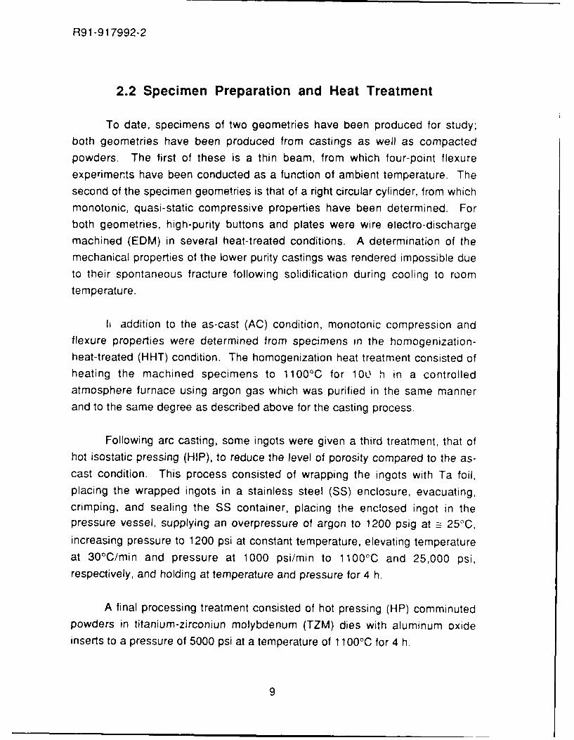
2.2 Specimen Preparation and Heat Treatment
To date, specimens of two geometries have been produced for study;both geometries have been produced from castings as well as compactedpowders. The first of these is a thin beam, from which four-point flexureexperiments have been conducted as a function of ambient temperature. Thesecond of the specimen geometries is that of a right circular cylinder, from whichmonotonic, quasi-static compressive properties have been determined. Forboth geometries, high-purity buttons and plates were wire electro-dischargemachined (EDM) in several heat-treated conditions. A determination of themechanical properties of the lower purity castings was rendered impossible dueto their spontaneous fracture following solidification during cooling to roomtemperature.
h addition to the as-cast (AC) condition, monotonic compression andflexure properties were determined from specimens in the homogenization-heat-treated (HHT) condition. The homogenization heat treatment consisted ofheating the machined specimens to 1100'C for 10L h in a controlledatmosphere furnace using argon gas which was purified in the same mannerand to the same degree as described above for the casting process.
Following arc casting, some ingots were given a third treatment, that ofhot isostatic pressing (HIP), to reduce the level of porosity compared to the as-cast condition. This process consisted of wrapping the ingots with Ta foil,placing the wrapped ingots in a stainless steel (SS) enclosure, evacuating,crimping, and sealing the SS container, placing the enclosed ingot in thepressure vessel, supplying an overpressure of argon to 1200 psig at = 25°C,
increasing pressure to 1200 psi at constant temperature, elevating temperatureat 30°C/min and pressure at 1000 psi/min to 11000C and 25,000 psi,
respectively, and holding at temperature and pressure for 4 h,
A final processing treatment consisted of hot pressing (HP) comminuted
powders in titanium-zirconiun molybdenum (TZM) dies with aluminum oxideinserts to a pressure of 5000 psi at a temperature of 1100C for 4 h.
9

R91-917992-2
Comminution of cast buttons from both the high purity and the nominal
purity starting materials was accomplished using a standard ball mill with
stainless steel comminutors, following which the alloy powders were graded
with standard metal sieves. Ball milling and subsequent grading of powders
were accomplished both in a protective atmosphere and in laboratory air, the
former making use of an air-tight glove box following evacuation and a thorough
purge with flowing argon. Powder which remained +325 mesh following
comminution, that is, that which failed to pass through the 325 mesh sieve, wasrecycled through the ball milling and sieving processes. In order to determine
the effets of powder size on the density and microstructure of hot pressings,
powder which was sieved to -400 mesh was produced, hot pressed, and
examined as well.
2.3 Microscopy
Optical (OM), scanning electron (SEM), and transmission electronmicroscopies (TEM) and selected area electron diffraction (SAED) have been
applied in complementary fashion to characterize the microstructures of the Fe-
modified AI3Ti alloy in the AC and HHT conditions. To capitalize on mutualinterests common to researchers at UTRC and the University of Illinois, UTRChas supplied undeformed and compressively deformed specimens to Professor
H. R. P. Inoue of the Department of Materials Science and Engineering for TEM
and electron diffraction analyses. Undeformed (virgin) and monotonically
compressed cylindrical specimens were sectioned for TEM into discs having
dimensions of 1 mm thickness and 4 mm diameter. The sectioning plane was
perpendicular to the compressive axis, the axis of rotational symmetry for the
cylinders, again accomplished using wire EDM. Discs for TEM weremechanically polished and subsequently electropolished to electron
transparency using a twin-jet polisher. TEM and SAED were conducted using a
Hitachi H-800 microscope operated at 200 keV.
10

R91-917992-2
2.4 Mechanical Behavior
As noted above, the mechanical properties of AC and HHT materialswere determined by monotonic four-point flexure and compression
experiments. Both configurations made use of a servo-hydrau c testingmachine, the temperature range for testing was from 22 to 1100003, and thestrain rate was 3.5 x 10⁻⁴/s. All flexure and compression experiments were
accomplished in an atmosphere of purified argon.
11

R91-917992-2
3. RESULTS AND DISCUSSION
3.1 Microscopic Observations and Crystallographic
Orientation of Second Phase Precipitates
3.1.1 Microstructures
Optical microscope observations showed that as arc-cast samples
consist of a two-phase microstructure containing an L1 2 phase and a second
phase, as shown in Fig 1. This second phase has planar faults which may be
twins which have formed in order to accommodate interfacial strain with the LI2matrix, as shown in Fig. 2. After homogenization, this second phase almost
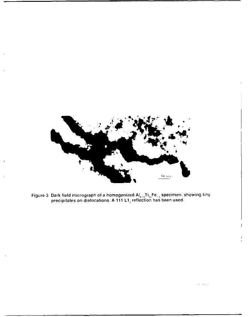
completely disappears; that is, the present alloy becomes essentially singlephase with an L1 2 structure. Transmission electron microscope observations of
homogenized specimens, however, revealed tiny precipitates on dislocation
segments, as shown in Fig. 3. Although it is not yet clear whether these tinyprecipitates are the residues of the second phase, they may play a significant
role in providing good mechanical properties at high temperature. Since theseprecipitates are small in size and in quantity, in the present work,
characterization has been performed on fine plate-shaped precipitates present
in abundance in as-arc-cast specimens.
Two types of fine precipitates have been observed in as arc-cast
specimens. Typical examples are shown in Figs. 4 and 5. Figure 4 shows fine
band-shaped precipitates which have formed heterogeneously along grown-in
and thermal-stress-induced dislocations, while Fig. 5 shows fine plate-shapedprecipitates having formed homogeneously in grains of the L1 2 matrix. Such
heterogeneous precipitates are about 20 nm thick and show fringes with afringe thickness of about 2-3 nm. These precipitates are considered to be
similar to those observed in homogenized specimens, as shown in Fig. 3.
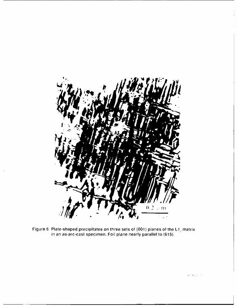
Microstructural observations have revealed that plate-shaped
precipitates occur homogeneously parallel to {001} planes of Li 2 matrix. In Fig.
5, plate-shaped precipitates are clearly seen to have formed parallel to (100)
12

R91-917992-2
planes. The diffraction pattern taken from the area of this micrograph shows
evident streaks, corresponding to precipitates parallel to (100) planes. Carefulobservation of this figure reveals that there are also precipitates which are
parallel to (010) and (001) planes. The presence of precipitates which haveformed on three sets of {001} planes is seen clearly in Fig. 6.
3.1.2 Crystal structure of plate-shaped precipitates
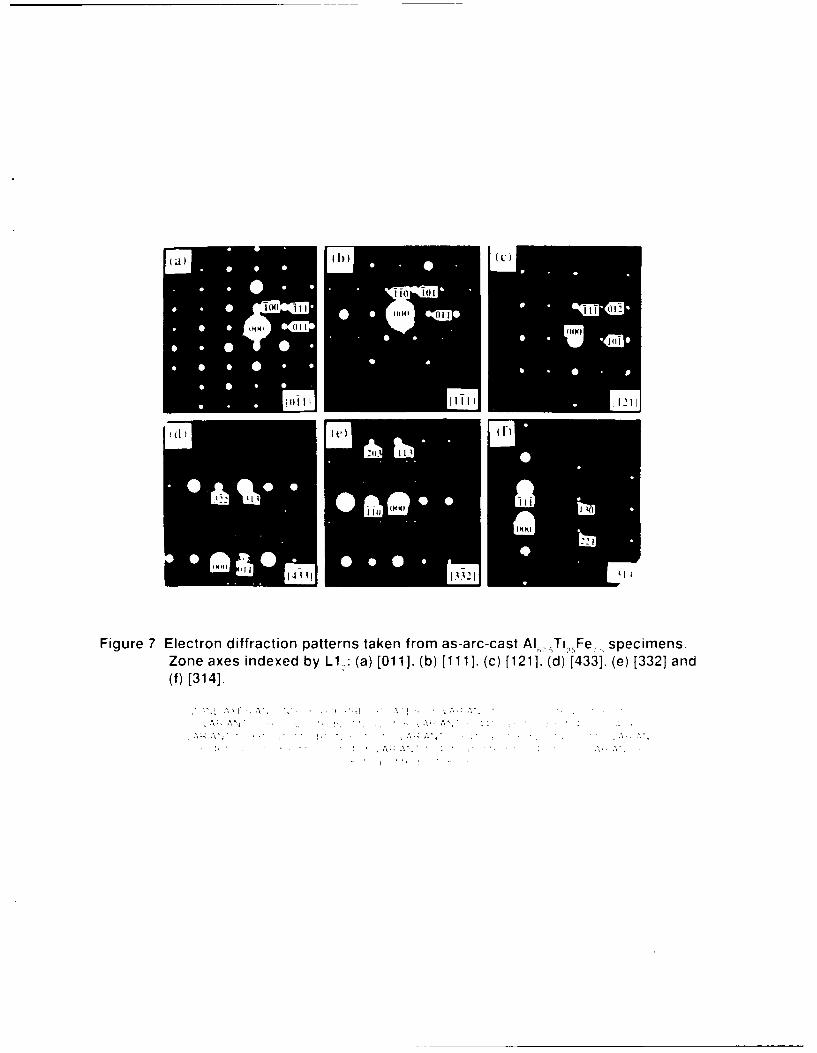
The crystal structure of plate-shaped precipitates which have formed on{001) planes was determined using electron diffraction patterns taken from arc-
cast specimens. It was noticed that when the direction of the incident electronbeam was parallel to zone axes of the matrix having low Miller indices, no extradiffraction spots were observed except streaks, which pass through diffraction
spots of the L1 2 matrix and are perpendicular to {001} planes of the matrix.They are, for example, [011], [1111, and [121], as shown in Fig. 7(a,b,c).
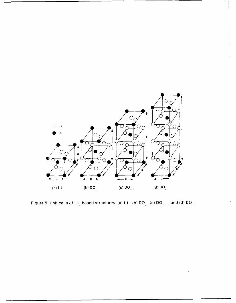
Conversely, many extra spots appeared in the case when the incident electronbeam was parallel to zone axes having high Miller indices, as shown in Fig.7(d,e,f). These extra spots cannot be indexed by assuming DO 22 and DO 2 3
structures, all of which are L1 2-based structures, as shown in Fig. 8(b,d).Taking into consideration that some extra spots appear at positions h/3, k/3, 1/3and 2h/3, 2k/3, 21/3, where h, k and I are Miller indices of the L1 2 matrix, anotherLi 2-based structure was assumed, which is composed of three Li 2 unit cells,
as shown in Fig. 8(c). However, this structure also cannot explain most of the
extra spots observed.
A new ordered tetragonal structure proposed for the observed plate-shaped precipitates is shown in Fig. 9. The unit cell of this tetragonal structure
is composed of six fcc unit cells containing 4 titanium atoms and 20 aluminumatoms. It should be noted that this structure is aluminum rich compared with the
L12-based structures shown in Fig. 8. The atomic ratio (AI:Ti) of this proposed
structure is 5:1, which is compared to a ratio of 3:1 for all the structures shown inFig. 8. Although iron atoms are not shown in Fig. 9, they are considered to
locate randomly at aluminum sites. Assuming this ordered tetragonal structure,
all the diffraction patterns shown in Fig. 7 can be indexed.
13

R91-917992-2
In order to index the diffraction patterns shown in Fig. 7, the followinglattice parameters are used:
appt = a. = 0.394 nm, and
Cppt = 6 x a = 2.364 nm,
where "t is the phase having L1 2 crystal structure.
In addition, the following consideration is also needed. From the
observations of the habit planes of the plate-shaped precipitates, there are six
possible orientation relationships between this precipitate phase and the L12matrix phase, suggesting the presence of six variants. However, due toequivalency, the total number of variants reduces to three. These three variantsmust be taken into account in indexing diffraction patterns taken from arc-cast
specimens. The orientation relationships for these variants are as follows:
variant 1: a [100] ppt /a [100] L1 2
b [010] ppt /b [010] L12
c [001] ppt /c [001] Li 2 ,
variant 2: b [010] ppt /a [100] L12
c [001] ppt /b [010] L12
a [100] ppt /c [001] Li 2 ,
variant 3: c [001] ppt //a [1001 L12
a [1001 ppt /b [0101 L12
b [010] ppt /c [001] Li 2 .
Under the assumption of this proposed structure and these three
orientation relationships, all extra spots can be indexed, as shown in Fig.
7(d,e,f).
14

R91-917992-2
3.2 Comparison of Fracture Properties between HIP andHHT Conditions
3.2.1 Microstructures
Previous optical microscope observations (Ref. 25) have revealed blocky
second-phase precipitates in as-cast specimens. In addition, it has also been
observed by transmission electron microscopy that there are both fine platelets(10 nm wide) forming homogeneously along {001} planes and band-shaped
precipitates forming heterogeneously along dislocations. After HIPing, such
blocky precipitates disappear. In their place, structures with a dendriticmorphology appear in the form of crosses, which seem to have some specific
orientation relationship with the L1 2 matrix, as shown in Fig. 10. These could
be phantom dendrites, a residual dendritic pattern which appears afterprecipitates nucleate and grow in the dendrite cores. After homogenization
annealing, conversely, the alloy becomos essentially single phase with a very
small volume fraction of precipitates having nucleated along dislocations (Ref.
23). As will be shown below, room-temperature ductility is improved by HIPing.Hence, it is of great importance to identify microstructures of HIPed specimens
and to determine the relationship between these microstructures and fractureproperties. Such a study is currently in progress.
3.2.2 Temperature dependence of yield stress and ductility
Both HHTed and HIPed specimens were deformed in compression at
various temperatures. Yield stress values obtained were plotted as a function of
test temperature. No anomalous temperature dependence of the yield stresshas been obtained, which is a common and important property of many nickel-
based L1 2-type compounds such as Ni3AI and Ni3Ge. As shown in Fig. 11, theyield stress decreases slightly from room temperature to 4000C, remaining
almost constant through 7500C, and then decreasing again at higher
temperatures. Similar temperature dependence has been observed also inPt3AI having the same L1 2 structure (Ref. 26). The absence of an anomalous
15
R91-917992-2
temperature dependence of yield stress in the present alloy is rather interesting
because transmission electron microscope observations have revealed that
screw dislocations cross slip from {111} to {001} planes in the alloy when
deformed at 11000C (Ref. 23). Among many nickel-based L1 2 -type
compounds, such cross slipping is known to be the primary origin of the
anomalous temperature dependence of the yield stress (Ref. 27).
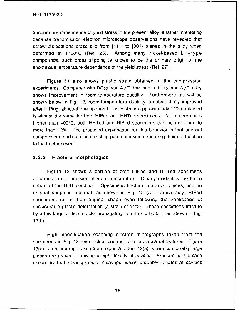
Figure 11 also shows plastic strain obtained in the compression
experiments. Compared with D022-type AI3 Ti, the modified L1 2-type AI3Ti alloy
shows improvement in room-temperature ductility. Furthermore, as will be
shown below in Fig. 12, room-temperature ductility is substantially improved
after HIPing, although the apparent plastic strain (approximately 11%) obtained
is almost the same for both HIPed and HHTed specimens. At temperatures
higher than 4000C, both HHTed and HIPed specimens can be deformed to
more than 12%. The proposed explanation for this behavior is that uniaxial
compression tends to close existing pores and voids, reducing their contribution
to the fracture event.
3.2.3 Fracture morphologies
Figure 12 shows a portion of both HIPed and HHTed specimens
deformed in compression at room temperature. Clearly evident is the brittle
nature of the HHT condition. Specimens fracture into small pieces, and no
original shape is retained, as shown in Fig. 12 (a). Conversely, HIPed
specimens retain their original shape even following the application of
considerable plastic deformation (a strain of 11%). These specimens fracture
by a few large vertical cracks propagating from top to bottom, as shown in Fig.
12(b).
High magnification scanning electron micrographs taken from the
specimens in Fig. 12 reveal clear contrast of microstructural features. Figure
13(a) is a micrograph taken from region A of Fig. 12(a), where comparably large
pieces are present, showing a high density of cavities. Fracture in this case
occurs by brittle transgranular cleavage, which probably initiates at cavities
16

R91-917992-2
formed upon solidification, Fig. 13(b). As seen in this figure, fracture surfacesare relatively smooth but not parallel to any crystallographic planes with lowMiller indices. Essentially similar structures are obtained from region B of Fig.12(a), where the specimen Fig. 12(a) becomes fragmented upon fracture.Compared to fracture surfaces for HHTed specimens, however, fracturesurfaces are rather rough and irregular in the case of HIPed specimens, Fig.13(c). In addition, both intergranular and transgranular fractures occur, asshown in Fig. 13(d). It should be noted that cavities are reduced significantlywith retention of a small density of cavities after HIPing, as shown in Fig. 13(d).Intergranular fracture in this case has probably occurred due to strengtheningagainst transgranular fracture through the reduction in the size and density ofcavities. Fracture surfaces of HIPed and HHTed specimens are also observedafter deformation in compression at 400, 750, and 1100°C. In both cases, nosignificant change in fracture morphologies has been observed by increasingthe test temperature, but it appears that fracture surfaces become more irregularand rugged with increasing temperature.
3.2.4 Dislocation structure
The structure of dislocations introduced in HHT specimens by
deformation in compression at room temperature has been investigated bymeans of HREM. Figure 14 is a micrograph taken from a thin foil parallel to the(001) plane, showing a pair of superlattice partial dislocations with a Burgersvector of a/2[101] on a (111) plane. In the micrograph, the imaging atoms areconsidered to be titanium atoms located at the corner sites of the L12 unit cells.Taking the lattice parameter of the alloy as 0.395 nm and the angle between the(001) and (111) planes into consideration, a spacing of 11 nm between thepaired superlattice dislocations is obtained. It is obvious in this case that these
dislocations do not lie on any {001} planes but lie on the (111) plane.
17

R91-917992-2
The APB energies, y APB, can be calculated using the equation for screw
dislocations,YAPB = G b2/2n r,
where G is the shear modulus, b the Burgers vector and r the spacing between
two screw dislocations. Using a value for G of 84 GPa (Ref. 25), a Burgersvector for 1/2[101] of 0.279 nm, and the measured superpartial separation of 11
nm, the APB energy is calculated to be 95 mJ/m 2 . This value is much lower
than those reported for AI 3 Sc (313 mJ/m 2 ) (Ref. 22) and AI-23Ti-6Fe-5V (274mJ/m 2) (Ref 22). According to the Rice-Thomson criterion (Ref. 20), dislocations
are considered to be emitted readily at or near crack tips for the present alloy
due to the large separation between the two superpartial dislocations. This
suggests that the alloy is intrinsically relatively ductile: hence it should be
possible to improve the ductility of this alloy through the complete elimination of
porosity.
18
R91-917992-2
4. SUMMARY AND CONCLUSIONS
The crystal structure of the stoichiometric AI3 Ti intermetallic compound
can be modified from the D022 to the L12 structure by adding 7.5 at.% Fe to
substitute for a portion of aluminum. This alloy is essentially single phase after
homogenization at 1000C for 100 h with a very small volume fraction of
precipitates having formed along dislocations. Conversely, in the case of the
as-cast condition, the alloy contains band-like precipitates which have firried
along dislocations and a high density of very thin, plate-shaped precipitates
which are parallel to {001} planes of the L12 matrix. The crystal structure of
these plate-shaped precipitates is proposed to be an ordered tetragonal
structure consisting of six fcc unit cells stacked along the "c" axis. This
proposed structure contains 4 titanium atoms and 20 aluminum atoms with iron
atoms in substitution for aluminum atoms. All diffraction patterns obtained were
indexed by assuming this structure and two or three variants of the precipitate
phase. Since there is a possibility that titanium atoms can be located at
positions other than those proposed, detailed intensity calculations of diffra'"tion
patterns or high resolution electron microscopy may be needed to determine
atom positions accurately.
In addition, the room temperature ductility of an L1 2 -type AI 3 T. alloy
containing 7.5 at.% Fe has shown little improvement following hot isostatic
pressing (HIP) after arc casting. However, fracture occurs at room temperature
by brittle transgranular cleavage with a smooth surface in HHTed specimens,
while in HIPed specimens, fracture occurs by both transgranular and
intergranular modes. Transgranularly fractured surfaces in the latter case have
rough surfaces with fine structure, indicating ductile fracture, in contrast to the
behavior and fracture morphology of HHTed specimens. In both HIPed and
HHTed specimens, no fracture surfaces are flat and parallel to any
crystallographic planes. High resolution electron microscopy has revealed that
a pair of superlattice partial dislocations on a (111) plane have a spacing of
approximately 11 nm (2-3 times larger than that for AI-23Ti-6Fe-5V) giving an
antiphase boundary energy of 95 mJ/m 2 . Since this energy is relatively low, the
19

R91-917992-2
present alloy may be ductile because nf its ready emission of dislocations at
crack tips, accora;ng to the Rice-Thomson criterion. Improw -nent in the room-
temperature ductility of this alloy is attributed primarily to the reduction of a large
population of cavities which have formed upon arc casting.
20
R91-917992-2
5. WORK IN PROGRESS
Current efforts are being concentrated in several parallel areas, as noted
below.
5.1 Tensile and Fatigue Data
In order to determine the influence of powder particle size on tensile and
fatigue properties, a fixture has been devised, as shown in Figure 15. Thisfixture utilizes counter-rotating cams to grip "dogbone" shaped specimens,
machined so as to closely approximate the cam profiles of the fixture. The cams
rotate through radii of curvature profiles machined on specimen contact
surfaces as well as the reverse side of the specimen contacting cams. Thisfixture allows for line loading of specimens in the radii and blend areas. In
addition, as all four radii are loaded, this configuration produces specimen self-
alignment. The fixture has been fabricated out of TZM for elevated temperature
testing.
5.2 The Effects of Powder Size
A determination of the microstructure and properties of hot pressed
powder which has been comminuted and graded to -325 or -400 mesh from two
purities of starting materials is in progress. The major objective of this segment
of the study is to determine the influence of powder particle size on the
microstructure and properties of the 7.5 at.% Fe alloyed with AI 3Ti. Should the
density and properties of plates which have been hot pressed from -325 mesh
powder be equivalent or nearly equivalent to those of the -400 mesh product,
-325 mesh powder will be selected for use because of the increased yield and
decreased intensity of labor required for its production.
21
R91-917992-2
5.3 The Effects of Iron Content
To resolve the interesting microstructure noted in the cast and HIPed
alloy containing 7.5 at.% Fe, namely the presence of an interdendritic second
phase, master alloys containing 6.5 and 8.5 at.% Fe have been cast and are
being examined in several conditions, including as-cast, cast plus HHT, cast
plus HIP, and cast plus HIP plus HHT. The third of these treatments, the cast
plus HIP plus HHT, is being given to the 7.5 at.% alloy, as well, to determine if
the dendritic second phase is a non-equilibrium structure.
5.4 Niobium Alloy Studies
Efforts are currently in progress to produce additional alloy compositions,
in which Nb is added in substitution for Ti and the Al and Fe contents remain
constant at 67.5 and 7.5 at.%, respectively. As with the ternary compositions,
arc-cast ingots from these quaternary compositions ar to be produced,
comminuted, and consolidated using hot pressing and/or hot isostatic pressing
to produce plates, from which specimens to determine mechanical properties
are to be fabricated. For all alloy compositions, a major emphasis of the third
and final year of the contract is the determination of the fracture and fatigue
properties, as well as optimal fabrication procedures, for the several alloy
compositions identified.
22
R91-917992-2
6. REFERENCES
1. R. Von Mises, Z. Ang. Math. Mech., 8,161 (1928).
2. S.M. Copley, B.H. Kear and G.M. Rowe, Mater. Sci. Eng., 10, 87 (1972).
3. B.H. Kear, A.F. Giamei, J.M. Silcock and R.K. Ham, Scripta Metall., 2, 287(1968).
4. B.H. Kear, A.F. Giamei, G.R. Leverant and J.M. Oblak, Scripta Metall., 3,455 (1969).
5. B.H. Kear, J.M. Oblak and A.F. Giamei, Proc. Second Int'l Conf. onStrength of Metals and Alloys, 1155 (1970).
6. B.H. Kear, J.M. Oblak and A.F. Giamei, Metall. Trans., 1, 2477 (1970).
7. B.H. Kear, A.F. Giamei and J.M. Oblak, Scripta Metall., 4, 567 (1970).
8. J.E. Doherty, A.F. Giamei and B.H. Kear, Metall. Trans. A, 6A, 2195(1975).
9. A. Raman and K. Schubert, Z. Metallkd., 56, 99 (1965).
10. A. Seibold, Z. Metallkd., 72, 712 (1981).
11. S.C. Huang, E.L. Hall and M.F.X. Gigliotti, J. Mater. Res., 3,1 (1988).
12. W.O. Powers, J.A. Wert and C.D. Turner, Philos. Mag. A., 60, 227(1989).
13. J. Tarnacki and Y.W. Kim, Scripta Metall., 22, 329 (1988).
14. S. Mazdiyasni, D.B. Miracle, D.M. Dimiduk, M.G. Mendiratta and P.R.Subramanian, Scripta MetpIL, 23, 327 (1989).
15. J. Tarnacki and Y.-W. Kim, in Dispersion Strengthened Aluminum Alloys,Editors Y.W. Kim and W.M. Griffith, Warrendale, PA: The MetallurgicalSociety, 741 (1988).
16. M. Yamaguchi, Y. Umakoshi and T. Yamane, Philos. Mag. A, 55, 301(1987).
17. M. Yamaguchi, Y. Umakoshi and T. Yamane, in High TemperatureOrdered Intermetallic Alloys II, Editors N.S. Stoloff, C.C. Koch, C.T. Liuand 0. Izumi, Pittsburgh: Materials Research Society, 207 (1987).
23
R91-917992-2
18. K.S. Kumar and J.R. Pickens, Scripta Metall., 22, 1015 (1988).
19. C.D. Turner, W.O. Powers and J.A. Wert, Acta Metall., 37, 2635 (1989).
20. J.R. Rice and R. Thompson, Philos. Mag., 29, 73 (1974).
21. S. Zhang, J. P. Nic, and D. E. Mikkola, Scripta Metall., 24, 57 (1990).
22. E. P. George, W. D. Porter, H. M. Henson, W. C. Oliver, and B. F. Oliver, J.Mater. Res. 4, 78 (1989).
23. H. R. Pak, C. M. Wayman, L. H. Favrow, C. V. Cooper, and J. S. L. Pak,Mat. Res. Soc. Symp. Proc. (1990), in press.
24. W. D. Porter, K. Hisatsune, C. J. Spark,., W. C. Oliver and A. Dhere, Mat.Res. Soc. Symp. Proc. 133, 657 (1989).
25. E. P. George, J. A Horton, W. D. Porter, and J. H. Schneibel, J. Mater.Res. 5 1639 (0990).
26. n.M. Wee, 0. Noguchi, Y. Oya. and T. Suzuki, Trans. Jpn. Inst. Met. 21237 (1980).
27. H.-R. Pak, T. Saburi, and S. Nenno, Trans. Jpn. Inst. Met. 18 617 (1977).
24

Figure 1 Optical micrograph of an as-arc-cast Al, ,Ti 2 Fe,, alloy, showing atleast two phases.

Figure 2 Transmission electron micrograph of as-arc-cast Al. :Ti,,,Fe. alloy.showing a large faulted precipitate.
Ti F . shwngtn
Figure 3 Dark field micrograph of a homogenized AI,, Ti2,Fe, 5 speci m e n . s h o w in g t in yprecipitates on dislocations. A 111 LI 2 reflection has been used.

nilFigure 4 Heterogeneous precipitates along dislocation in an as-arc-cast
AI,. ,Ti, Fe, specimen.

}~t ra cet.
Figure 5 Plate-shaped precipitates in L12 grains of an as-arc-cast specimen (a) dark fieldimage of an ordered 100 reflection, and (b) [0121 zone axis of the L1, matrix.
tor
,Il
. 9
Figure 6 Plate-shaped precipitates on three sets of {001} planes of the Li, matrixin an as-arc-cast specimen. Foil plane nearly parallel to (615).
1(NW II 112
INN)
Figure 7 Electron diffraction patterns taken from as-arc-cast Al1, 5Ti ,2 Fe- , specimens.Zone axes indexed by Li1: (a) [011]. (b) [111]. (c) [121]. (d) [433], (e) [332] and(f) [314].
AV
0
0
a -- m0
(a) (btO '()DO,.()D .
Fig re Untacllsl ,-bsdOsrcurs a)L ( b)DO () DO,,,ad()D .

Figure 9 A proposed ordered tetragonal structure consisting of slx fcc unit cells

* -4V
ba
, TC
2 O-lim
F0 I0l~r 1(3~~)IC~iI s'~()vvirq ~.do, drilic !-(IJ( tLi '~ iI~ nHPM
s~~Jl~I. tf~' C Ii 1~I)V nalowctI~ h iFc~t, nmainiic~Iiir

400
U) 300LU
LU 200
LU
LiU
0
U 4
0 200 400 600 800(1 1000 1200
1EFMPFRATLJRE C
Figure 11 Temperature dependence of yield stress for Fe-modified L1,-type AI3Ti.

A !
Figure 12 Deformed specimens in compression at room temperature. (a) annealed forhomogenization; (b) HIPed.

AnA
Lw ww
Figure 13 High magnification scanning electron micrographs taken from homogenized
and HIPed specimens deformed at room temperature. (a) region A of Figure 3 (a):
(b) framed region of Figure 4 (a): (c) a central region of Figure 3 (b): and (d)
framed region of Figure 4 (c).

Figure 14 High-resolution electron micrograph showing pair of superlattice partialdislocations on a (111) plane having Burgers vector 1 2 [101]. Foil plane is(001). Solid lines are on atom plane: dotted lines are between atom planes.Dislocation cores are located near the center between the ends of the lines.

Fig. 15 Assembled and Exploded Views of Tensile/Compressive/Fatigue Fixture forBrittle Materials.