Embed Size (px)
Citation preview

Fast Towel Disinfecting Cabinet
Team 25 -- Yujie Wang and Christopher Willenborg and Harsh Agrawal ECE 445 Design Document — Spring 2019
TA: Kyle Michal

1 Introduction 1.1 Objective With society progressing rapidly, people have higher standards of living. The well-being of the population is imperative for any country. This awakening of rising concerns over personal health has led to a huge increase in the global personal hygiene market [1]. However, bath towels are often overlooked by people for how dirty they are. Sadly, more often than not, people wash their towels about two or three times a month, leaving their damp, warm towels to dry in dark, poorly ventilated bathrooms between uses. This creates a perfect environment for bacteria to thrive into a decent-sized colony on the towels. Although many of the bacteria are harmless, there is still a small portion that makes people sick. A study conducted by Charle Gerba, a microbiologist at the University of Arizona, suggests that nearly 90% of bathroom towels were contaminated with coliform bacteria and about 14% carried E.coli [2]. We would like to solve this problem by building a wall-mounted towel disinfecting and drying cabinet that uses UVC light to kill all the bacteria and dry it faster than air drying to prevent any bacteria to thrive on the towel. 1.2 Background The recommended uses between cleanings of a bath towel is every two to three days [3], but from speaking with our friends and acquaintances we have determined that the average person only cleans their towel once every 10-15 days. We would like to increase the personal health of people, by disinfecting one of the least likely places people expect to contain disease-causing bacteria. Currently, no products exist in the market to solve this problem. There are heated towel racks available that can dry your towel faster than air drying, but that does not prevent bacteria to grow on the towel. There are hot towel sterilization cabinets that use ozone or UV-C light intended to be used in salons and spas to keep cleaned face or hand towels damp, warm and bacteria-free [4]. Our product should be a sleek, disinfecting, and drying wall-mounted cabinet to keep bath towels clean and dry between uses. This cabinet should neutralize a substantial portion of the E. coli determined to be present on the towel.

1.3 High-level requirements
The cabinet shall be designed such that the UVC light, in a worst-case scenario, covers 85% or more of the towel as to kill the bacteria residing on the towel.
The humidity in the cabinet shall be no more than 50% upon completion, less than 7 hours. [5]
The cabinet shall not open while the UVC lights are on.
2 Design 2.1 Block Diagram
Figure 1 : Block Diagram
We will be using twelve UVC LEDs in our cabinet. To achieve full coverage under average conditions, we will put six lights in the door of the cabinet and six against the back wall. The front and back UVC lights will each be 3” away from the towel, plus or minus the thickness of the towel and mount thickness for the lights. The UVC light needs to come in contact with the surface that it is killing bacteria on. This makes it extremely important for the towel to be covered as much as possible by the light in order to kill the majority of bacteria residing on the towel. There will be a rod at the top with moveable clips to hang towel of any size that does not exceed the dimensions of inside

the cabinet. We will implement a heating element and fan into the bottom of our cabinet to successfully convection dry our towel and decrease humidity. There will be vents at the top of the cabinet for the fresh air to flow in and moist air to flow out. There will be a door lock to keep the door closed. The door lock is a necessity to keep the user from shining the harmful UVC light on them accidentally or on purpose. 2.2 Physical Design
Figure 2 : AutoCAD Dimensioning of Chassis
Our chassis needs to hang an entire bath towel inside of it, so the chassis will be fairly large and wide because of this. We would like to try and keep costs down by limiting the number of UVC lights used in our project. This will however increase the depth amount of distance from the light to the towel. If we were to use more lights, we could make the chassis much slimmer than our current model. The convection system that we will be implementing to dry the towel introduces the need for air movement in and out of the chassis. Inside of our chassis will be a plate near the top and plate near the bottom. The plate on the top will be used to keep the UVC light from shining out of the vents as much as possible, while still allowing sufficient air to flow in the cabinet for drying. The plate located at the bottom of the cabinet will be used to keep the user safe from touching the heating element in addition to functioning as part of our convection design. A fan will be mounted in the center of the top as well as the bottom plates as to sufficiently move the air inside of the chassis. We will hang the towel on a rod that is located beneath our upper plate inside of the chassis and runs parallel to the door.
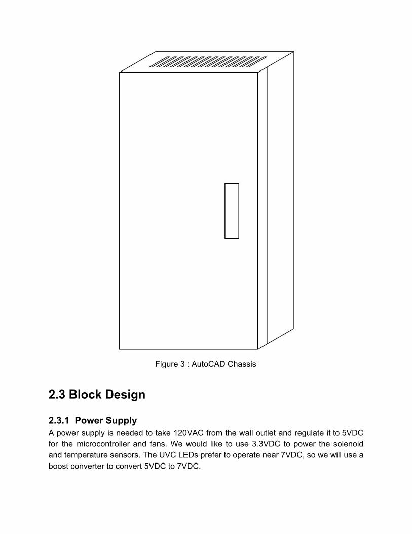
Figure 3 : AutoCAD Chassis
2.3 Block Design
2.3.1 Power Supply A power supply is needed to take 120VAC from the wall outlet and regulate it to 5VDC for the microcontroller and fans. We would like to use 3.3VDC to power the solenoid and temperature sensors. The UVC LEDs prefer to operate near 7VDC, so we will use a boost converter to convert 5VDC to 7VDC.
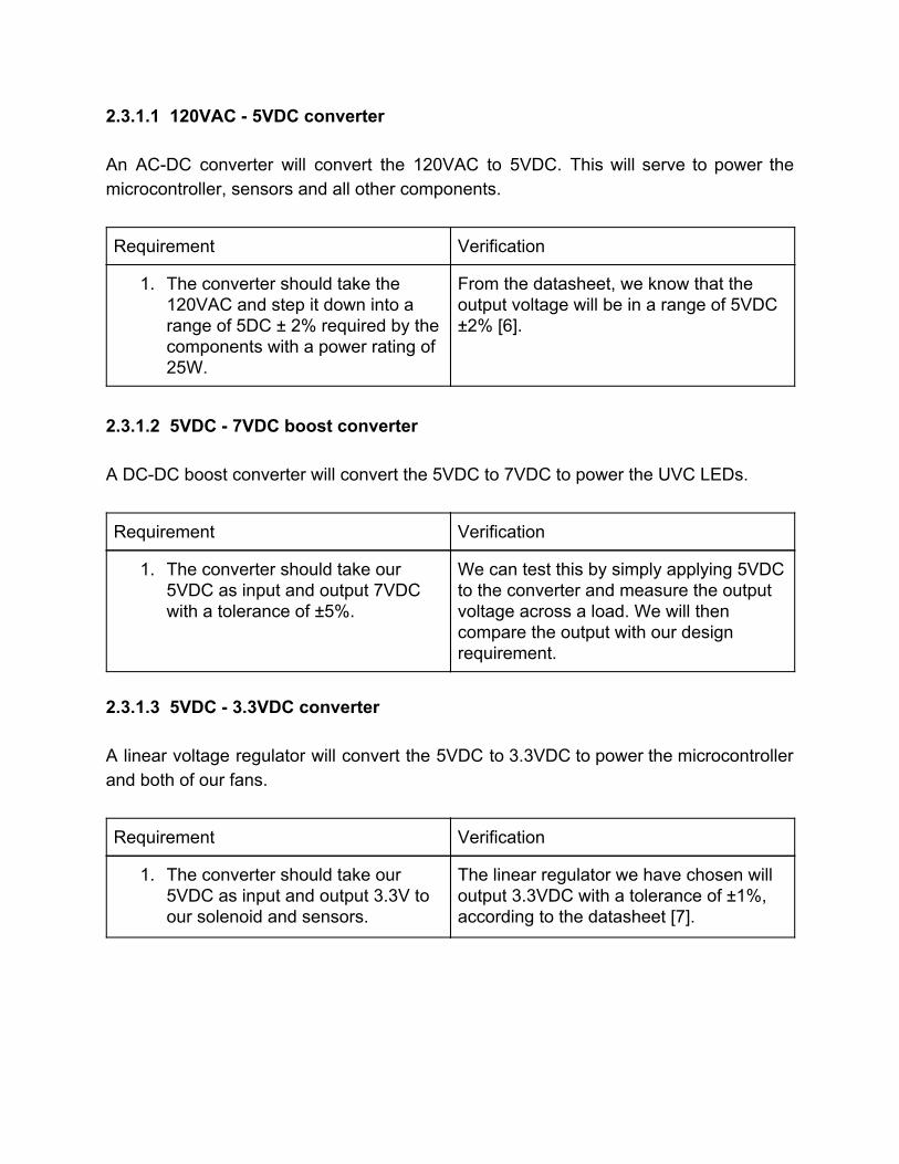
2.3.1.1 120VAC - 5VDC converter An AC-DC converter will convert the 120VAC to 5VDC. This will serve to power the microcontroller, sensors and all other components.
Requirement Verification
1. The converter should take the 120VAC and step it down into a range of 5DC ± 2% required by the components with a power rating of 25W.
From the datasheet, we know that the output voltage will be in a range of 5VDC ±2% [6].
2.3.1.2 5VDC - 7VDC boost converter A DC-DC boost converter will convert the 5VDC to 7VDC to power the UVC LEDs.
Requirement Verification
1. The converter should take our 5VDC as input and output 7VDC with a tolerance of ±5%.
We can test this by simply applying 5VDC to the converter and measure the output voltage across a load. We will then compare the output with our design requirement.
2.3.1.3 5VDC - 3.3VDC converter A linear voltage regulator will convert the 5VDC to 3.3VDC to power the microcontroller and both of our fans.
Requirement Verification
1. The converter should take our 5VDC as input and output 3.3V to our solenoid and sensors.
The linear regulator we have chosen will output 3.3VDC with a tolerance of ±1%, according to the datasheet [7].

2.3.2 Control Unit The control unit will control every operation of the device, specifically: accepting user input from the button, locking the door, controlling the UVC LEDs and drying unit, maintaining the desired temperature based on readings from the sensors, displaying status on the status LED.
Figure 4 : Controls Flowchart

2.3.2.1 Microcontroller The microcontroller (MCU) carries out all of the operations. It should ensure that the door remains locked during a disinfecting-drying cycle and pressing the button during the cycle has no effect. The microcontroller should have enough GPIO pins to support all of our sensors and signals. We will be using two temperature-humidity sensors, heating element, two fans, button, status LED, door lock and one signal for all UVC LEDs making a total of nine. We should reserve a few extra GPIO pins in the event that we need more sensors or wish to implement extra features. A reach goal for our microcontroller design would involve a way to interrupt and resume or quit the cycle at any point in the process.
Requirement Verification
1. Both sensors require about 1.1 mA to take regular measurements.
The datasheet specifies that the current is within the range of 1.2 mA to 1.46mA [8].
2. The microcontroller should output voltage within the range of 5V ±5%.
We can verify the control pins by measuring it with a voltmeter.
3. The microcontroller should keep the door locked during a disinfection-drying cycle and pressing the button during the cycle has no effect.
Trigger a cycle by pressing the button and make sure that the door does not open until the cycle is complete. Press the button a few times during the cycle to make sure it has no effect.
2.3.2.2 Temperature-Humidity Sensor The Temperature-Humidity sensor will provide temperature and humidity measurements of the air inside the cabinet to allow the control unit to maintain a set temperature inside the cabinet.
Requirements Verification
1. The temperature-humidity sensor must work in 3.3VDC ± 5% with 2.5mA maximum current.
Referencing the datasheet, we know that the sensor will accept a voltage in the range of 1.62VDC to 3.6VDC

[8].
2. Should read temperature with a ±1 accuracy and humidity with a ±5% accuracy.
We will take measurement from our sensors and compare the readings to those of an existing verified product, ensuring that they are within ±1 and 5% for humidity.
Figure 5 : Electrical Schematic for Thermistors
2.3.3 Disinfecting Unit This unit consists of the twelve UVC LEDs required to disinfect the towel. The MCU will turn the UVC LEDs on for a set amount of time to achieve the desired disinfection.
2.3.3.1 UVC LEDs The UVC LEDs will be mounted on the front and back of the cabinet such that they cover 85% of the surface area. They will shine UVC light on the towel, killing the bacteria, specifically E. Coli. Since the UVC LEDs draw more current than the MCU can provide they will be powered by the 7V boost converter and controlled using a gate.

Requirement Verification
1. The LED should work at 7 ±1 V with 100mA nominal current.
Provide a couple different voltages from 5V to 8V [9].
Check if the LEDs turns on.
2. The LEDs shall cover at least 85% of the towel.
We calculate the area covered by one LED in the configuration we will be implementing. Apply trigonometry to the distance from the towel and viewing angle of the LED to find the radius of our circle. Graphical derivation can be found in Tolerance Analysis.
Figure 6 : Electrical Schematic for UVC LEDs

2.3.4 Drying Unit The drying unit consists of a heating element, fan and vents to dry the towel and reduce the humidity in the cabinet to 50% in a reasonable amount of time (7 hours). We found a home study on the drying time under various circumstances. The study found that a towel "Indoors hanging from a hook” took “7 hours 58 minutes” to dry [5]. As long as we can dry the towel faster than if it were hanging from a hook, we would consider ourselves successful, but it would be most preferable for the towel to be dry within 7 hours. 2.3.4.1 Heating Element The heating element should be powerful enough to support successful convection without producing so much heat that it would pose a substantial fire threat.
Requirements Verification
1. Each heating element should work at 120VAC drawing a maximum of 1A.
Power the heating element with 120VAC.
Use a multimeter to measure the current ensuring that it is no more than 1A.
2.3.4.2 Fans We will be using two fans, one mounted at the bottom blowing air on the heating element and one mounted at the top blowing air inside on the towel creating a convection current.
Requirements Verification
1. Each fan should work at 5VDC drawing a maximum of 300mA.
Power the fan with a 5V power supply and check if the fan turns on.
The datasheet specifies that the current will be no more than 280mA [10].
2. The drying unit should reduce the humidity inside the cabinet to
Hang a wet towel in the cabinet and start a cycle. Check the cabinet after
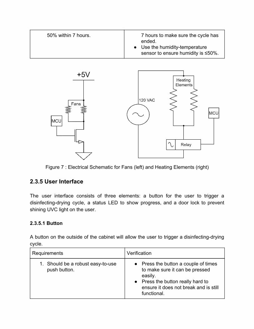
50% within 7 hours. 7 hours to make sure the cycle has ended.
Use the humidity-temperature sensor to ensure humidity is ≤50%.
Figure 7 : Electrical Schematic for Fans (left) and Heating Elements (right)
2.3.5 User Interface The user interface consists of three elements: a button for the user to trigger a disinfecting-drying cycle, a status LED to show progress, and a door lock to prevent shining UVC light on the user. 2.3.5.1 Button A button on the outside of the cabinet will allow the user to trigger a disinfecting-drying cycle.
Requirements Verification
1. Should be a robust easy-to-use push button.
Press the button a couple of times to make sure it can be pressed easily.
Press the button really hard to ensure it does not break and is still functional.

2.3.5.2 Status LED A status LED to show the three modes of operation: disinfecting (blue), drying (red), done (green).
Requirements Verification
1. RGB Common Anode LED that works at 5V drawing a maximum of 100mA current.
Connect common anode (CA) pin to 5V.
Connect red pin to GND via a 330Ω resistor. Connect green and blue pins to GND via 330Ω resistors. Check if the LED lights up showing red color.
Repeat the step above to ensure the LED can show green and blue colors also.
Check that the current is no more than 100mA on each route (CA - red, CA - green, CA - blue) using a multimeter.
2.3.5.3 Door Lock A door lock is required to keep the door closed throughout the duration of the disinfecting-drying cycle. The door will lock at the start of a cycle when the button is pressed and open when the cycle is complete.
Requirements Verification
1. A solenoid lock that can be operated at 3,3VDC drawing a maximum of 1.2A current.
The default position of the solenoid should be locked or active where it does not use any power.
Apply 3.3VDC and check if the solenoid unlocks.
The datasheet lists the resistance of the solenoid at 4.5 ohms. With 3.3V applied, the datasheet would suggest the current will be 0.733A [11].

Figure 8 : Electrical Schematic for Solenoid
2.3.6 Supporting Material
Figure 9 : PCB Layout

2.4 Tolerance Analysis One important tolerance we must maintain is the relative positions of UVC LED to the towel, so we can guarantee the most UVC coverage on the towel, while satisfying other specs of the design. The depth of the cabinet is designed to be 6’’, and the towel will be hung right in the middle. From the datasheet of our UVC LED, the LED plus the surface mount will have a 0.0945’’ thickness. Assuming there is no extra space under the surface mount and 0.1’’ thickness for the bath towel, we would have (3’’- 0.1’’-0.0945” = 2.81”) about 2.81 inches between the LED and the surface of the towel. Also from the datasheet of our UVC LED, the viewing angle of the LED is 120-140 degrees. There is no easy and safe way to measure the exact viewing angle of the LED we receive but assuming that any LED would have a viewing angle at least 120 degrees we would still be able to cover >85% of the towel, hence satisfying the first high-level requirement. We plan on placing six LEDs on each side of the towel. Treating the bath towel as a flat surface, we can construct a right triangle as shown in Figure 11. For the purpose of making the prototype work, we fix the dimensions of the towel to 18” x 27”. We can make the base of a right triangle the distance from our door, or rear panel, to the towel. We greatly reduced the price of our raw materials by making the depth of our chassis 6” and implementing 6 LEDs per side of the towel. We find the radius of coverage of the light by multiplying our distance to the towel from the wall (3”) by the tangent of half our viewing angle. Figure 11 demonstrates the UVC coverage on a towel with the optimal arrangement of the LEDs assuming a worst-case UVC LED view angle of 120 degrees and an average case viewing angle of 130 degrees. With this optimal arrangement, we have 93.3% coverage worst-case and 99.98% coverage on an average-case. We can see through the virtual model or by going through the math that we will receive sufficient coverage in a worst-case scenario and our average coverage should be sufficiently close to 100%.

Figure 10 : Geometric Derivation 2
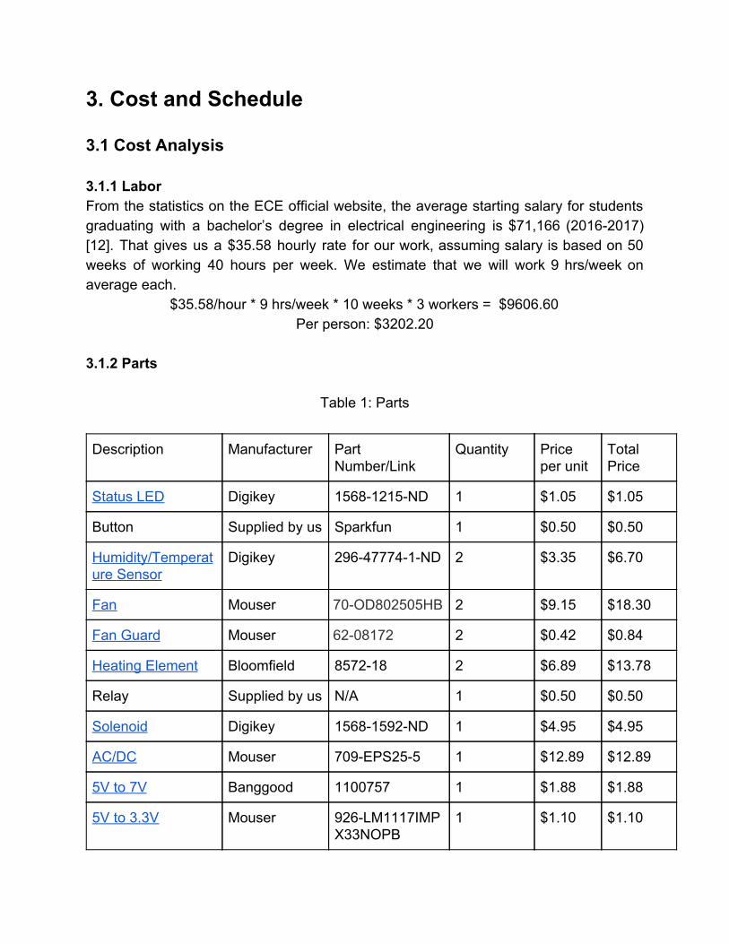
3. Cost and Schedule 3.1 Cost Analysis 3.1.1 Labor From the statistics on the ECE official website, the average starting salary for students graduating with a bachelor’s degree in electrical engineering is $71,166 (2016-2017) [12]. That gives us a $35.58 hourly rate for our work, assuming salary is based on 50 weeks of working 40 hours per week. We estimate that we will work 9 hrs/week on average each.
$35.58/hour * 9 hrs/week * 10 weeks * 3 workers = $9606.60 Per person: $3202.20
3.1.2 Parts
Table 1: Parts
Description Manufacturer Part Number/Link
Quantity Price per unit
Total Price
Status LED Digikey 1568-1215-ND 1 $1.05 $1.05
Button Supplied by us Sparkfun 1 $0.50 $0.50
Humidity/Temperature Sensor
Digikey 296-47774-1-ND
2 $3.35 $6.70
Fan Mouser 70-OD802505HB 2 $9.15 $18.30
Fan Guard Mouser 62-08172 2 $0.42 $0.84
Heating Element Bloomfield 8572-18 2 $6.89 $13.78
Relay Supplied by us N/A 1 $0.50 $0.50
Solenoid Digikey 1568-1592-ND 1 $4.95 $4.95
AC/DC Mouser 709-EPS25-5 1 $12.89 $12.89
5V to 7V Banggood 1100757 1 $1.88 $1.88
5V to 3.3V Mouser 926-LM1117IMPX33NOPB
1 $1.10 $1.10

MCU Digikey ATMEGA328-PU-ND
1 $1.96 $1.96
Crystal Oscillator Digikey 300-6034-ND 1 $0.59 $0.59
UVC LED Digikey 1807-1022-ND 12 $11.75 $141
Chassis Machine Shop N/A 1 Free N/A
Chassis Material (Polypropolene)
Machine Shop N/A $.03/sq. in. $73.92 $73.92
Rated Cable Menards N/A 1 (10 feet) $5 $5
Water Repellent NANOPROTECH
857111005055 1 $25.73 $25.73
Clips to Hold Towel Digikey CTM-30C-ND 4 $0.32 $1.28
PCB orders PCBWay N/A 1 $15 $15
Total $326.97 3.1.3 Grand Total $9606.60 + $326.97 = $9933.57. 3.2 Schedule We want to reserve a week of time towards the end of the semester when our product will be expected to work for any unexpected delays or unpredicted issues. We will not have much to do for a week or two until our parts start arriving, but we can work on the exact wiring diagrams, microcontroller encoding, and PCB prototype design. We do not know for sure when the machine shop will have our chassis ready either, which could put us back off of our schedule.
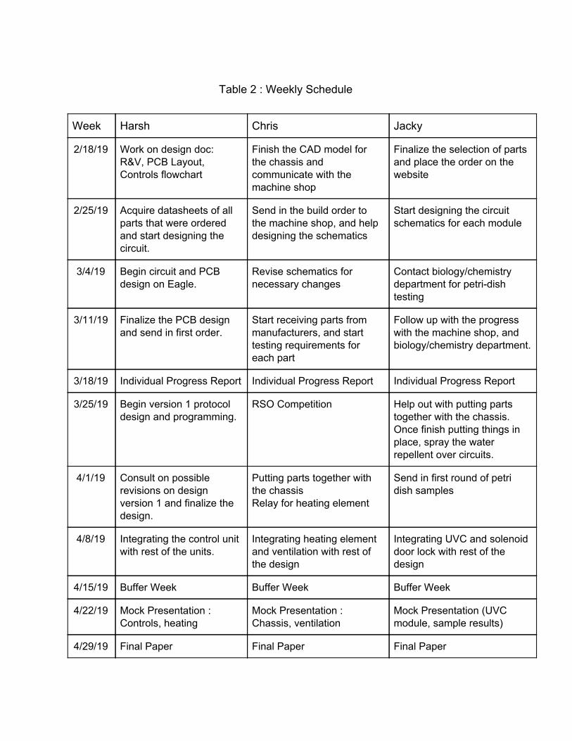
Table 2 : Weekly Schedule
Week Harsh Chris Jacky
2/18/19 Work on design doc: R&V, PCB Layout, Controls flowchart
Finish the CAD model for the chassis and communicate with the machine shop
Finalize the selection of parts and place the order on the website
2/25/19 Acquire datasheets of all parts that were ordered and start designing the circuit.
Send in the build order to the machine shop, and help designing the schematics
Start designing the circuit schematics for each module
3/4/19 Begin circuit and PCB design on Eagle.
Revise schematics for necessary changes
Contact biology/chemistry department for petri-dish testing
3/11/19 Finalize the PCB design and send in first order.
Start receiving parts from manufacturers, and start testing requirements for each part
Follow up with the progress with the machine shop, and biology/chemistry department.
3/18/19 Individual Progress Report Individual Progress Report Individual Progress Report
3/25/19 Begin version 1 protocol design and programming.
RSO Competition Help out with putting parts together with the chassis. Once finish putting things in place, spray the water repellent over circuits.
4/1/19 Consult on possible revisions on design version 1 and finalize the design.
Putting parts together with the chassis Relay for heating element
Send in first round of petri dish samples
4/8/19 Integrating the control unit with rest of the units.
Integrating heating element and ventilation with rest of the design
Integrating UVC and solenoid door lock with rest of the design
4/15/19 Buffer Week Buffer Week Buffer Week
4/22/19 Mock Presentation : Controls, heating
Mock Presentation : Chassis, ventilation
Mock Presentation (UVC module, sample results)
4/29/19 Final Paper Final Paper Final Paper

4. Ethics There will most definitely be some safety concerns that we need to account for with our project. One of the first that comes to mind is the potential harm that can come from UVC light exposure. To mitigate this concern and abide by IEEE Code of Ethics, #1: “to hold paramount…” [13], the first step we will take is to implement a self-locking mechanism that will not allow users to open the door and expose themselves to UVC light when our cabinet during a towel cleaning cycle. The second step we will take is to inform the user of all potential hazards with using this product and explain how to avoid harming themselves complying with the IEEE Code of Ethics, #1: “to disclose promptly factors that might endanger the public” [13]. One way the user can be exposed to UVC light is if they intentionally leave the cabinet open and trigger a cycle. We haven’t incorporated a solution to this in our design but if we have extra time we might add a feature to only trigger a cycle if the door is closed. We will need some sort of safe voltage regulation if we are to use the 120VAC from a wall plug. The hazards of using 120V in wet conditions are quite obvious when it comes to the potential of electrocution. We would need to safely step down the voltage to power the heating element, sensors, lights, and microcontroller. The moisture that we expect to experience inside of our cabinet could be detrimental to any PCBs that we use. We currently plan on spraying the PCBs with a hydrophobic coat of sort to keep the water that accumulates on the surface from shorting any of our components. We would also like to incorporate some type of ventilation if we have spare time in an effort to keep moisture from accumulating on our components. Another way to combat this issue would be to keep the microcontroller in a enclosure inside the cabinet so that the moisture does not reach it. Since our product is in the development phase and is more of a proof-of-concept design at this point, we conservatively claim that our project would kill most but not all bacteria. After formulating a method to test the effectiveness of our disinfection unit, we would report the achieved bacteria kill rate. This is the encouraged practice by the IEEE Code of Ethics, #3 “to be honest and realistic in stating claims...” [13]. We are incorporating a convection system, which means we will need a heater. The issue we expect the user could encounter with the heating system is potential fire hazards such as lighting up the towel on fire. We will design the system to maintain a

safe temperature inside the cabinet to avoid the possibility of burning the towel. We would also purchase a fan with a guard to avoid any potential injury to the user if they intentionally put their hand in the fan. We know that wires are not typically a safety concern, but due to the nature and size of our project, we will have wires spread all throughout our cabinet. We do not want the wires to be in the way of other components, so we plan on wrapping wires in a bunch against the wall. References [1] Transparencymarketresearch.com. (2019). Personal Hygiene Market - Global Industry Analysis, Size, Share, Growth, Trends and Forecast 2016 - 2024. [online] Available: https://www.transparencymarketresearch.com/personal-hygiene-market.html [Accessed 5 Mar. 2019]. [2] Abrams, A. (2017). Your Towels Are Way Dirtier Than You Think. [online] Time. Available: http://time.com/4918624/wash-towels-bacteria/ [Accessed 5 Mar. 2019]. [3] Slawek, E. (2017). How often should you wash bath towels?. [online] TODAY.com. Available: https://www.today.com/series/one-small-thing/how-often-should-you-wash-bath-towels-t111625 [Accessed 5 Mar. 2019]. [4] Spaandequipment.com. (n.d.). 24 Piece Hot Towel Cabinet With Sterilizer. [online] Available: https://www.spaandequipment.com/24-pc-Hot-towel-Cabinet-with-Sterilizer.html?gclid=CjwKCAiA767jBRBqEiwAGdAOr7zDc3eanhPuNXax0SBSggijkTD04Tyqdp1ScAjEOlhTeTxRveb9ohoCYAAQAvD_BwE [Accessed 5 Mar. 2019]. [5] Polat, A. (2017). How Long Does It Really Take For A Quick-Dry Towel To Dry? - foXnoMad. [online] foXnoMad. Available: https://foxnomad.com/2017/10/17/long-really-take-quick-dry-towel-dry/ [Accessed 5 Mar. 2019]. [6] 25W Single Output Switching Power Supply. (2018). [pdf] Mean Well, pp.1-2. Available: http://www.meanwellusa.com/productPdf.aspx?i=693#1 [Accessed 5 Mar. 2019].

[7] LM1117 800-mA Low-Dropout Linear Regulator. (2016). [pdf] TEXAS INSTRUMENTS, pp.5-16. Available: http://www.ti.com/lit/ds/symlink/lm1117.pdf [Accessed 5 Mar. 2019]. [8] HDC2010 Low Power Humidity and Temperature Digital Sensors. (2018). [pdf] TEXAS INSTRUMENTS, pp.3-7. Available: http://www.ti.com/lit/ds/symlink/hdc2010.pdf [Accessed 5 Mar. 2019]. [9] RayVio XD UV LEDs (280nm). (n.d.). [pdf] RayVio, pp.1-10. Available: https://media.digikey.com/pdf/Data%20Sheets/RayVio%20PDFs/RVXD(280_nm)RevQ_DS.pdf [Accessed 5 Mar. 2019]. [10] OD8025 Series. (n.d.). [pdf] Orion Fans. Available: https://media.digikey.com/pdf/Data%20Sheets/Orion%20Fans%20PDFs/OD8025_Rev_Dec_2007.pdf [Accessed 5 Mar. 2019]. [11] SPECIFICATION. (n.d.). [pdf] SHENZHEN ZONHEN ELECTRIC APPLIANCES, pp.1-4. Available: https://cdn.sparkfun.com/datasheets/Robotics/ZHO-0420S-05A4.5%20SPECIFICATION.pdf [Accessed 5 Mar. 2019]. [12] ece.illinois.edu. (2017). Undergraduate Curricula and Advising :: ECE ILLINOIS. [online] Available: https://ece.illinois.edu/academics/ugrad/curriculum/ [Accessed 5 Mar. 2019]. [13] Ieee.org. (n.d.). IEEE Code of Ethics. [online] Available: https://www.ieee.org/about/corporate/governance/p7-8.html [Accessed 5 Mar. 2019].