Embed Size (px)
Citation preview

Fast-Fold
Installation Manual
®
[Revision: May 16, 2008 0-115-565, ©Rytec Corporation, 2002]


TABLE OF CONTENTS
PAGE
INTRODUCTION. . . . . . . . . . . . . . . . . . . . . . . . . . . . . . . . . . . . . . . . . . . . .1
DOOR SERIAL NUMBER(S). . . . . . . . . . . . . . . . . . . . . . . . . . . . . . . . . . . . . . . . . . .1
HOW TO USE MANUAL . . . . . . . . . . . . . . . . . . . . . . . . . . . . . . . . . . . . . . . . . . . . . .1
INSTALLATION . . . . . . . . . . . . . . . . . . . . . . . . . . . . . . . . . . . . . . . . . . . . .2
MATERIAL, TOOLS, AND EQUIPMENT . . . . . . . . . . . . . . . . . . . . . . . . . . . . . . . . .2
ADDITIONAL REQUIREMENTS. . . . . . . . . . . . . . . . . . . . . . . . . . . . . . . . . . . . . . . .2
Labor and Site Requirements. . . . . . . . . . . . . . . . . . . . . . . . . . . . . . . . . . . . .2
Forklift Requirements . . . . . . . . . . . . . . . . . . . . . . . . . . . . . . . . . . . . . . . . . . .2
Electrician’s Responsibilities . . . . . . . . . . . . . . . . . . . . . . . . . . . . . . . . . . . . .2
Floor-Loop Activator Requirements . . . . . . . . . . . . . . . . . . . . . . . . . . . . . . .2
Fill-In Material Requirements . . . . . . . . . . . . . . . . . . . . . . . . . . . . . . . . . . . . .2
GENERAL ARRANGEMENT OF DOOR COMPONENTS . . . . . . . . . . . . . . . . . . . .3
ANCHORING METHODS . . . . . . . . . . . . . . . . . . . . . . . . . . . . . . . . . . . . . . . . . . . . .3
Concrete, Block, or Brick Walls . . . . . . . . . . . . . . . . . . . . . . . . . . . . . . . . . . .3
Wood, Block, Brick, or Insulated Walls . . . . . . . . . . . . . . . . . . . . . . . . . . . . .3
Insulated Walls . . . . . . . . . . . . . . . . . . . . . . . . . . . . . . . . . . . . . . . . . . . . . . . .4
UNCRATING . . . . . . . . . . . . . . . . . . . . . . . . . . . . . . . . . . . . . . . . . . . . . . . . . . . . . . .5
LOCATING CENTERLINE OF DOOR OPENING . . . . . . . . . . . . . . . . . . . . . . . . . . .6
LOCATING SIDE PANELS . . . . . . . . . . . . . . . . . . . . . . . . . . . . . . . . . . . . . . . . . . . .6
SIDE PANELS . . . . . . . . . . . . . . . . . . . . . . . . . . . . . . . . . . . . . . . . . . . . . . . . . . . . . .7
HEAD ASSEMBLY . . . . . . . . . . . . . . . . . . . . . . . . . . . . . . . . . . . . . . . . . . . . . . . . . .8
SIDE PIPES . . . . . . . . . . . . . . . . . . . . . . . . . . . . . . . . . . . . . . . . . . . . . . . . . . . . . . . .9
PANELS. . . . . . . . . . . . . . . . . . . . . . . . . . . . . . . . . . . . . . . . . . . . . . . . . . . . . . . . . .10
Panel Alignment . . . . . . . . . . . . . . . . . . . . . . . . . . . . . . . . . . . . . . . . . . . . . .12
Trimming Panels (Puralon Panels Only) . . . . . . . . . . . . . . . . . . . . . . . . . . .13
Attaching Panels to Side Pipes (Side Pipe Doors) . . . . . . . . . . . . . . . . . . .13
KNOB AND ROPE TIE INSTALLATION. . . . . . . . . . . . . . . . . . . . . . . . . . . . . . . . .13
Rope Tie Doors Only . . . . . . . . . . . . . . . . . . . . . . . . . . . . . . . . . . . . . . . . . . .13
SEAL . . . . . . . . . . . . . . . . . . . . . . . . . . . . . . . . . . . . . . . . . . . . . . . . . . . . . . . . . . . .16
Center Seal – Hypalon. . . . . . . . . . . . . . . . . . . . . . . . . . . . . . . . . . . . . . . . . .16
Side Seal. . . . . . . . . . . . . . . . . . . . . . . . . . . . . . . . . . . . . . . . . . . . . . . . . . . . .16
INSULATED SIDE PANELS AND SEALED PURALON PANELS . . . . . .16
STANDARD SIDE PANELS AND SEALED PURALON PANELS . . . . . .16
FREEZER DOOR SIDE SEAL . . . . . . . . . . . . . . . . . . . . . . . . . . . . . . . .18
PANEL CLEANING . . . . . . . . . . . . . . . . . . . . . . . . . . . . . . . . . . . . . . . . . . . . . . . . .18
DOOR SEALING . . . . . . . . . . . . . . . . . . . . . . . . . . . . . . . . . . . . . . . . . . . . . . . . . . .18
MANUAL BRAKE RELEASE (OPTIONAL ITEM) . . . . . . . . . . . . . . . . . . . . . . . . .18
DEFROST SYSTEM (FREEZER DOOR OPTION) . . . . . . . . . . . . . . . . . . . . . . . . .18
Heat Lamp Fixture Installation . . . . . . . . . . . . . . . . . . . . . . . . . . . . . . . . . . .18
Lamp Fixture Wiring and Bulb Installation . . . . . . . . . . . . . . . . . . . . . . . . .19
LAMP BULB AND RED SLEEVE INSTALLATION . . . . . . . . . . . . . . . . .20
Lamp Fixture Adjustment (Warm-Side and Cold-Side Mounted Doors). .20
Heat Lamp Controls . . . . . . . . . . . . . . . . . . . . . . . . . . . . . . . . . . . . . . . . . . .22
Blower Controls. . . . . . . . . . . . . . . . . . . . . . . . . . . . . . . . . . . . . . . . . . . . . . .22
BLOWER SPEED . . . . . . . . . . . . . . . . . . . . . . . . . . . . . . . . . . . . . . . . . .22
BLOWER HEATER . . . . . . . . . . . . . . . . . . . . . . . . . . . . . . . . . . . . . . . . .22
Hard-Panel Door . . . . . . . . . . . . . . . . . . . . . . . . . . . . . . . . . . . . . . . . . . . . . .22
FIN ADJUSTMENT . . . . . . . . . . . . . . . . . . . . . . . . . . . . . . . . . . . . . . . . .22
ELECTRICAL SYSTEM. . . . . . . . . . . . . . . . . . . . . . . . . . . . . . . . . . . . . . . . . . . . . .23
Door Close and Open Limit Position . . . . . . . . . . . . . . . . . . . . . . . . . . . . . .23
CLOSE LIMIT . . . . . . . . . . . . . . . . . . . . . . . . . . . . . . . . . . . . . . . . . . . . .23
OPEN LIMIT . . . . . . . . . . . . . . . . . . . . . . . . . . . . . . . . . . . . . . . . . . . . . .24
Hard-Panel Door Remote Limit Switch (Mandatory Item if Hard-Panel Door Is Installed) . . . . . . . . . . . . . . . . . .24
FINAL CHECKS . . . . . . . . . . . . . . . . . . . . . . . . . . . . . . . . . . . . . . . . . . . . . . . . . . .25
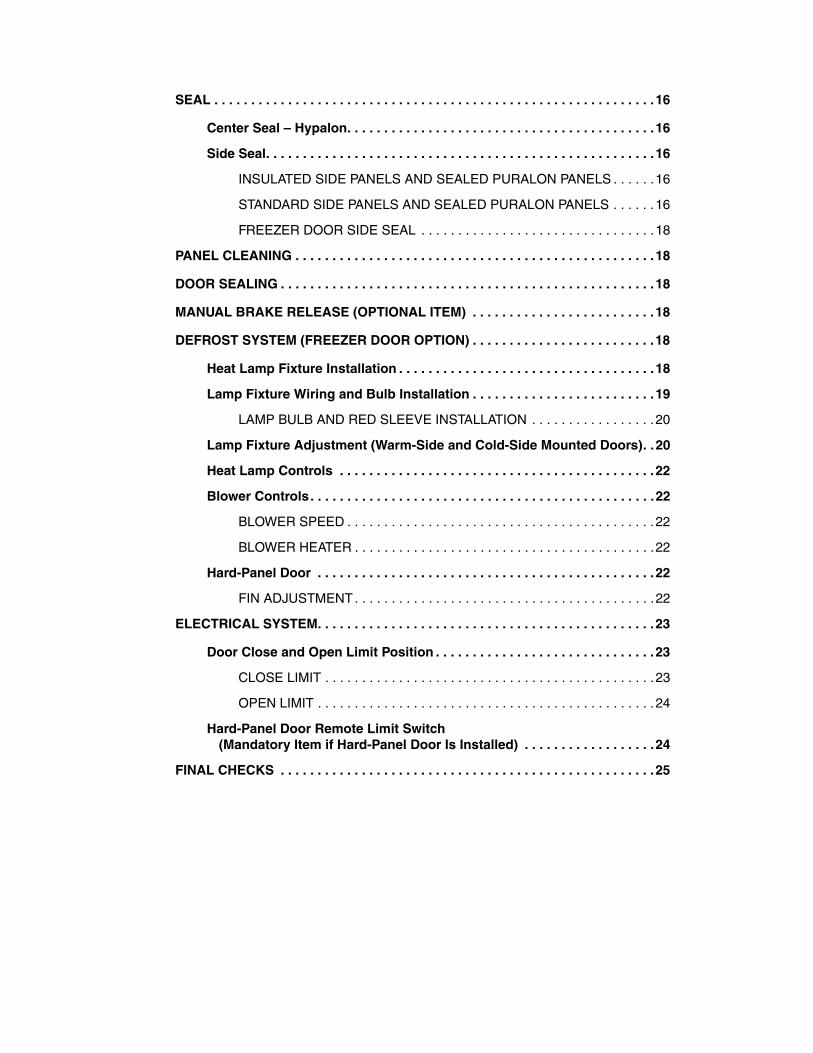
INTRODUCTION—DOOR SERIAL NUMBER(S)
INTRODUCTIONThe installation of your Rytec Fast-Fold® Door is not dif-ficult if you adhere to the procedures outlined in this manual. Any unauthorized changes to these proce-dures, or failure to follow the steps as outlined, will auto-matically void our warranty. Any changes to the working parts, assemblies, or specifications as written, that are not authorized by Rytec Corporation, will also cancel our warranty. The responsibility for the successful oper-ation and performance of this door is yours.
DO NOT INSTALL, OPERATE, OR PERFORM MAIN-TENANCE ON THIS DOOR UNTIL YOU READ AND UNDERSTAND ALL THE INSTRUCTIONS IN THIS MANUAL.
If you have any questions, contact your Rytec represen-tative or call the Rytec Customer Support Department at 800-628-1909. Always refer to the serial number of the door when calling the representative or Customer Support. The serial number plate is located inside one of the side panels.
Refer to the Rytec System 3 Drive & Control Installation & Owner’s Manual for general information about wiring connections. The actual schematic for your particular door has been shipped with the door and is located inside the control panel.
DOOR SERIAL NUMBER(S)
To obtain your DOOR SERIAL NUMBER, there are three universal locations where this information can be found. These are at the inside of either side column (approxi-mately eye level), on the drive motor, and on the inside door of the System 3 control panel. (See Figure 1.)
IMPORTANT: When installing multiple doorsof the same model but in differ-ent sizes, verify the serial num-ber in the control panel with theone in the side column.
Figure 1
HOW TO USE MANUAL
Throughout this manual, the following key words are used to alert the reader of potentially hazardous situa-tions, or situations where additional information to suc-cessfully perform the procedure is presented:
WARNING is used to indicate the potentialfor personal injury if the procedure is notperformed as described.
CAUTION is used to indicate the potentialfor damage to the product or propertydamage if the procedure is not followed asdescribed.
IMPORTANT: IMPORTANT is used to relayinformation CRITICAL to thesuccessful completion of theprocedure.
NOTE: NOTE is used to provide additional infor-mation to aid in the performance of theprocedure or operation of the door, but notnecessarily safety related.
A1500157
Serial Number PlateLocated Inside One of the Side Panels
Drive Motor
System 3Control Panel
1

INSTALLATION—MATERIAL, TOOLS, AND EQUIPMENT
INSTALLATION
MATERIAL, TOOLS, AND EQUIPMENT
1. Threaded rod (¹�₂-in. diameter) and other various wall anchor hardware and material. Concrete anchor bolts (¹�₂-in. diameter).(See “ANCHORING METHODS” on page 3.)
2. Assorted shim stock.
3. Double-sided tape (for attaching shims to wall).
4. Carpenter’s level (4-ft. minimum length).
5. Carpenter’s square.
6. Hammer drill.
7. Masonry drill bit (for ¹�₂-in. diameter anchors).
8. Hammer or mallet, and block of wood.
9. Crowbar or pry bar.
10. Assorted hand tools (pliers, tape measure, etc.).
11. Socket and wrench sets.
12. Water level, line level, or transit.
13. Two ladders (taller than height of door opening).
14. Forklift (see “Forklift Requirements” below).
ADDITIONAL REQUIREMENTS
Labor and Site Requirements
1. Two installers.
2. An electrician is required for making all electrical connections. (See the Rytec System 3 Drive & Con-trol Installation & Owner’s Manual.)
3. 100% accessibility to the door opening during the entire installation process. No traffic should be allowed to pass through the opening while the door is being installed.
Forklift Requirements
A forklift supplied by the customer, dealer, or installer is mandatory for the safe and proper installation of this door. The forklift should have:
• 2,000-pound lift capacity
• minimum height ability — door height, plus 12 in.
• side-shift capability (desired)
Electrician’s Responsibilities
For complete details on the responsibilities of the elec-trician, refer to the Rytec System 3 Drive & Control Installation & Owner’s Manual.
Floor-Loop Activator Requirements
If a floor-loop activator was ordered and shipped with your Rytec Door, the following additional items will be required to install the activator.
NOTE: For complete floor-loop installation instruc-tions, refer to the manual that was shippedwith the activator.
1. Concrete saw (with water cooling attachment).
2. Water supply and garden hose.
3. Wet/dry shop vacuum.
4. 200–500 feet of 16-gauge, 19-strand, type XLPE, copper, crosslink polyethylene jacket wire (or equiv-alent). The size of the floor loop will determine the length of wire required.
5. Bondo P606 Flexible Embedding Sealer (or equiva-lent) — required to fill saw cuts in floor after the acti-vator is installed. For cold temperature applications, Bondo P610 Speed Set must be added to the P606 to ensure the sealer cures properly.
Fill-In Material Requirements
Some applications may require the use of a door pullout (extension) to gain clearance of an existing obstruction between the door and the door opening. The following materials can be used to fill the space or gap between the door and the door opening.
1. 16-gauge hot-rolled sheet steel.
2. 2-in. x 2-in. x ³�₁₆-in. angle iron.
2

INSTALLATION—GENERAL ARRANGEMENT OF DOOR COMPONENTS
GENERAL ARRANGEMENT OF DOOR COMPONENTS
Figure 2 shows the location of the major components of the door and the general placement of the associated sub-assemblies for a typical installation.
This illustration is provided to you for informational pur-poses only. It should not be relied upon solely during the installation of your door and its sub-assemblies.
Figure 2
NOTE: The above illustration shows the front sideof the door. Left and right are determinedwhen viewing the front side of the door.
ANCHORING METHODS
Correct anchoring of the side panels to the wall and the floor is important for the smooth and safe operation of the door. The wall material should be strong enough to support the weight of the door and all wall anchors.
Figure 3 through Figure 6 show anchoring methods for various types of walls. Use the method that is best suited for your particular installation site.
All necessary anchoring hardware and material required for the installation of this door is the responsibility of the door owner. If you have any questions, call your Rytec representative or the Rytec Customer Support Depart-ment at 800-628-1909.
NOTE: Use ¹�₂-in. diameter threaded through boltsor ¹�₂-in. diameter threaded rods to anchorthe door to all wall applications. Use ¹�₂-in.diameter concrete anchor bolts to anchorthe door to a concrete floor.
Concrete, Block, or Brick Walls
Figure 3
Wood, Block, Brick, or Insulated Walls
Figure 4
A1500110
Side
Puralon
Serial Number PlateLocated Inside One of the Side Panels
Side
Head Assembly
Pipe
Panel
Panels
FusedDisconnect
RytecControlPanel Turn
Arms
SidePanel
SidePipe
A0500005
Side
Expansion
Concrete Wall
Panel
Anchor
A0500037
Side
Through Boltor Threaded Rod
Crush Plate (¹�₂-in. Thick,6-in. x 8-in.Steel)
Wood
PanelWall
3

INSTALLATION—ANCHORING METHODS
Insulated Walls
Figure 5
Figure 6
A0500039
Insulated Wall
Through Boltor Threaded Rod
SidePanel
Aluminum-Clad Lumber(Front and Back Side — Full Length)
A0500038
Through Boltor Threaded Rod
Insulated
Aluminum-Clad Lumber(Back Side — Full Length)
Wall
SidePanel
4
INSTALLATION—UNCRATING
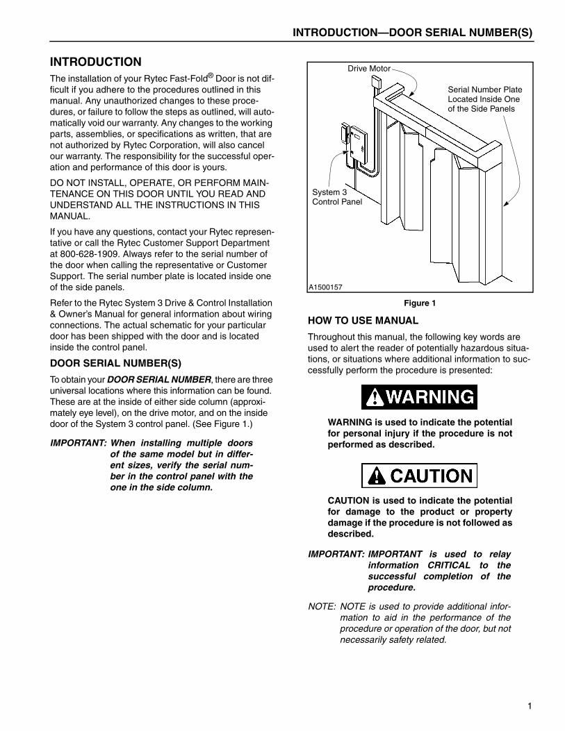
UNCRATING
Your Rytec Door has been crated to allow for minimal handling of assemblies during the installation process.
NOTE: Remove parts and sub-assemblies fromthe shipping crate in the order directedthroughout this installation manual.
1. Remove the top of the crate.
NOTE: The material packed on the upper level ofthe crate must be removed before the frontof the crate can be opened. Also, the frontof the head assembly faces the front of thecrate. (See Figure 7.)
Figure 7
2. Remove the door’s side panels from the upper level of the crate.
Storing the flexible, Puralon™1 panels incor-rectly can cause problems in the way the pan-els will seal later on. To retain the naturalcurvature of each panel, it is critical to storethe panels in a similar manner in which theywere found inside the shipping crate (curveside down). If a panel is to be rolled, flip it overand roll it with the label side of the panel fac-ing up (curve side up). Rolling a panel againstthe curve or storing it incorrectly could flattenthe natural curvature of the panel.
3. Remove the Puralon panels from the crate. The panels have been stacked flat with the curve side of each panel facing down, label side facing down. Once the panels are removed from the crate, store them flat with the curve side facing down. Also, pro-tect the panels from damage. (See Figure 8.)
Figure 8
NOTE: If you find it necessary to roll the panels,they must be rolled with the curve side ofthe panel facing up. DO NOT allow thePuralon panels to remain rolled for morethan a few hours. Allowing them to remainrolled for too long, may effect the way thepanels seal the opening. (See Figure 9.)
To relax the panels before they are hung inplace, roll them out flat and flip them overwith the label facing down, curve sidedown.
Figure 9
4. Remove the front of the crate.
1. Puralon is a trademark of Rytec Corporation.
A1500001
Crate
Side Panels and Puralon Panels Packed
Head Assembly, Control Panel, and Small Parts Carton Packed
in Upper Level
in Lower Level
A1500044
Natural Curve
Face Label SideDown when StoringPanels Flat
A1500045
Face Curve Side ofPanel Up whenRolling Up Panel(Label Facing Up)
5
INSTALLATION—LOCATING CENTERLINE OF DOOR OPENING
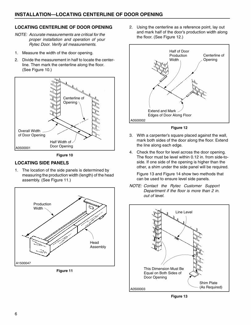
LOCATING CENTERLINE OF DOOR OPENING
NOTE: Accurate measurements are critical for theproper installation and operation of yourRytec Door. Verify all measurements.
1. Measure the width of the door opening.
2. Divide the measurement in half to locate the center-line. Then mark the centerline along the floor.(See Figure 10.)
Figure 10
LOCATING SIDE PANELS
1. The location of the side panels is determined by measuring the production width (length) of the head assembly. (See Figure 11.)
Figure 11
2. Using the centerline as a reference point, lay out and mark half of the door’s production width along the floor. (See Figure 12.)
Figure 12
3. With a carpenter’s square placed against the wall, mark both sides of the door along the floor. Extend the line along each edge.
4. Check the floor for level across the door opening. The floor must be level within 0.12 in. from side-to-side. If one side of the opening is higher than the other, a shim under the side panel will be required.
Figure 13 and Figure 14 show two methods that can be used to ensure level side panels.
NOTE: Contact the Rytec Customer SupportDepartment if the floor is more than 2 in.out of level.
Figure 13
A0500001
Centerline of Opening
Overall Widthof Door Opening
Half Width of Door Opening
A1500047
ProductionWidth
HeadAssembly
A0500002
Half of DoorCenterline ofOpening
Production
Extend and MarkEdges of Door Along Floor
Width
A0500003
Line Level
This Dimension Must Be Equal on Both Sides of Door Opening
Shim Plate (As Required)
6
INSTALLATION—SIDE PANELS
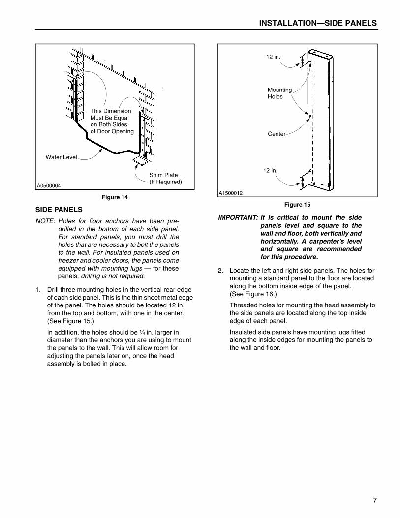
Figure 14
SIDE PANELS
NOTE: Holes for floor anchors have been pre-drilled in the bottom of each side panel.For standard panels, you must drill theholes that are necessary to bolt the panelsto the wall. For insulated panels used onfreezer and cooler doors, the panels comeequipped with mounting lugs — for thesepanels, drilling is not required.
1. Drill three mounting holes in the vertical rear edge of each side panel. This is the thin sheet metal edge of the panel. The holes should be located 12 in. from the top and bottom, with one in the center. (See Figure 15.)
In addition, the holes should be ¹�₄ in. larger in diameter than the anchors you are using to mount the panels to the wall. This will allow room for adjusting the panels later on, once the head assembly is bolted in place.
Figure 15
IMPORTANT: It is critical to mount the sidepanels level and square to thewall and floor, both vertically andhorizontally. A carpenter’s leveland square are recommendedfor this procedure.
2. Locate the left and right side panels. The holes for mounting a standard panel to the floor are located along the bottom inside edge of the panel.(See Figure 16.)
Threaded holes for mounting the head assembly to the side panels are located along the top inside edge of each panel.
Insulated side panels have mounting lugs fitted along the inside edges for mounting the panels to the wall and floor.
A0500004
This Dimension Must Be Equal on Both Sides of Door Opening
Water Level
Shim Plate (If Required)
A1500012
Mounting
Center
12 in.
12 in.
Holes
7
INSTALLATION—HEAD ASSEMBLY
Figure 16
3. Place the right side panel perpendicular to the floor as shown in Figure 17. Align the outside edge of the panel with the line indicating the production width of the door.
NOTE: Place shims under and behind each panelas required. Use double-sided tape totemporarily attach the shims to the wall orside panel.
Figure 17
4. Anchor the panel to the wall and floor as required. (See “ANCHORING METHODS” on page 3.) DO NOT tighten the mounting hardware at this time. The panels may have to be repositioned once the head assembly is in place.
5. Mount the left side panel following the same proce-dure used for mounting the right side panel.
HEAD ASSEMBLY
1. Remove the control panel, small parts carton, and any other items from within the crate that might block the head assembly during its removal.
2. Manually release the motor brake located on the end of the drive motor. Then, to prevent the forklift from damaging the head assembly, move the turn arms to their fully open position to allow the forks to clear the underside of the head assembly. (The turn arms are the mechanical arms that the panels will be hung from.)
The head assembly must be securely fas-tened to the forklift before it is lifted intoposition on top of the side panels. Failureto safely secure the head assembly canresult in damage to the assembly andcause injury to personnel.
DO NOT remove the forklift out from underthe head assembly until the side panelsare securely fastened to the wall of thebuilding and the head assembly issecurely fastened to the side panels.
Handle the head assembly with care toprevent damage to the turn arms.
3. Remove the head assembly from the crate using a forklift or other suitable means. Secure the head assembly to the forks using clamps or other equiv-alent method. (See Figure 18.)
Floor Mounting Holes (Inside Edge)
Threaded Holes (Top) Mounting Lugs
Insulated
(Insulated SidePanels Only)
Side Panel
A1500013, A1500015, A1500014
A1500048
Insulated Side Panel
Carpenter’s Level
Production Width LineFloor
Mounting Holes
Carpenter’s
Mounting Holes
Square
8
INSTALLATION—SIDE PIPES
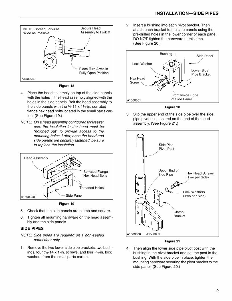
Figure 18
4. Place the head assembly on top of the side panels with the holes in the head assembly aligned with the holes in the side panels. Bolt the head assembly to the side panels with the ⁵�₈-11 x 1¹�₂-in. serrated flange hex head bolts located in the small parts car-ton. (See Figure 19.)
NOTE: On a head assembly configured for freezeruse, the insulation in the head must be“notched out” to provide access to themounting holes. Later, once the head andside panels are securely fastened, be sureto replace the insulation.
Figure 19
5. Check that the side panels are plumb and square.
6. Tighten all mounting hardware on the head assem-bly and the side panels.
SIDE PIPES
NOTE: Side pipes are required on a non-sealedpanel door only.
1. Remove the two lower side pipe brackets, two bush-ings, four ⁷�₁₆-14 x 1-in. screws, and four ⁷�₁₆-in. lock washers from the small parts carton.
2. Insert a bushing into each pivot bracket. Then attach each bracket to the side panels using the pre-drilled holes in the lower corner of each panel. DO NOT tighten the hardware at this time.(See Figure 20.)
Figure 20
3. Slip the upper end of the side pipe over the side pipe pivot post located on the end of the head assembly. (See Figure 21.)
Figure 21
4. Then align the lower side pipe pivot post with the bushing in the pivot bracket and set the post in the bushing. With the side pipe in place, tighten the mounting hardware securing the pivot bracket to the side panel. (See Figure 20.)
A1500049
Secure Head
Place Turn Arms in Fully Open Position
NOTE: Spread Forks as Wide as Possible Assembly to Forklift
A1500050
Head Assembly
Side Panel
Serrated Flange Hex Head Bolts
Threaded Holes
A1500051
BushingSide Panel
Lower Side
Front Inside Edgeof Side Panel
Hex Head
Lock Washer
Pipe Bracket
Screw
A1500008 A1500009
Side Pipe
Hex Head Screws (Two per Side)
Lock Washers (Two per Side)
Clamp
Upper End of
Pivot Post
Side Pipe
Bracket
9
INSTALLATION—PANELS
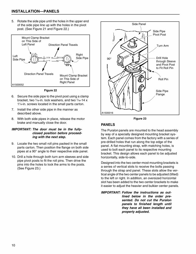
5. Rotate the side pipe until the holes in the upper end of the side pipe line up with the holes in the pivot post. (See Figure 21 and Figure 22.)
Figure 22
6. Secure the side pipe to the pivot post using a clamp bracket, two ⁷�₁₆-in. lock washers, and two ⁷�₁₆-14 x 1¹�₄-in. screws located in the small parts carton.
7. Install the other side pipe in the manner as described above.
8. With both side pipes in place, release the motor brake and manually close the door.
IMPORTANT: The door must be in the fully-closed position before proceed-ing with the next step.
9. Locate the two small roll pins packed in the small parts carton. Then position the flange on both side pipes at a 90° angle to their respective side panel.
10. Drill a hole through both turn arm sleeves and side pipe pivot posts to fit the roll pins. Then drive the pins into the holes to lock the arms to the posts. (See Figure 23.)
Figure 23
PANELS
The Puralon panels are mounted to the head assembly by way of a specially designed mounting bracket sys-tem. Each panel comes from the factory with a series of pre-drilled holes that run along the top edge of the panel. A flat mounting strap, with matching holes, is used to bolt each panel to its respective mounting bracket. This design allows each panel to be adjusted horizontally, side-to-side.
Designed into the two center-most mounting brackets is a series of vertical slots to receive the bolts passing through the strap and panel. These slots allow the ver-tical angle of the two center panels to be adjusted (tilted) to the left or right. In addition, an oversized horizontal slot has been added to the two center brackets to make it easier to adjust the heavier and bulkier center panels.
IMPORTANT: Follow the instructions as out-lined below in the order pre-sented. Do not cut the Puralonpanels to finished length untilthey have all been installed andproperly adjusted.
Right Side Pipe
Left Side Pipe
Direction Panel Travels
Direction Panel Travels
Mount Clamp Bracket on This Side of Left Panel
A1500052
Mount Clamp Bracket on This Side of Right Panel
A1500016
90°
Side Panel
Side Pipe
Roll Pin
Side Pipe Pivot Post
Turn Arm
Drill Holethrough Sleeveand Pivot Post
Flange
to Fit Roll Pin
10
INSTALLATION—PANELS
Each panel has been tagged with an identification num-ber to indicate its position as it should appear when mounted on the door. The tag is located on the inside face of the curve. When facing the front side of the door, the panels (and their associated mounting brackets) are numbered from left-to-right, with panel #1 on the far, left-hand side of the door. (See Figure 24.)
IMPORTANT: To ensure the door panels sealproperly, it is critical that thepanels be hung in their num-bered order, with the naturalcurve of each panel facing thedirection shown in Figure 24.
Figure 24
1. The metal mounting strap used to attach each panel to its respective mounting bracket has been installed on the panel at the factory. Before a panel can be installed, first remove the nuts that are threaded onto the bolts that pass through the mounting strap and panel. Leave the strap and bolts in place once the nuts are removed.(See Figure 25.)
Figure 25
2. Working from the front side of the door, left-to-right, lift each panel in place and attach it to its corre-sponding mounting bracket. (See Figure 26.)
Make sure the number on the panel matches up with the correct mounting bracket and that the pan-els are hung with all mounting bolts pointing toward the back side of the door.
Also, it is important that each mounting strap (and panel) is centered on its respective mounting bracket — later on, if it becomes necessary, the panels can be repositioned.
Figure 26
1 2 3 4 5 6
Panel Numbers
1 2 3 4 5 6
Panel Numbers
A1500017
A1500035 Overlapping Panels
Front Side
Seamed Panelsof Door
Front Sideof Door
A1500119
Remove AllHex Nuts
PuralonPanel
Metal MountingStrap
NOTE:Leave Hex Boltsand Strap in Place.Only Remove Hex Nuts.
A1500120
Secure MountingStrap to MountingBracket
MountingBracket (Along
Turn Arm
Panel withMounting Strap
Bottom of TurnArm)
11
INSTALLATION—PANELS
NOTE: The metal mounting straps used with thetwo, center-most panels each have an extra-long bolt located in the center hole. Thislonger bolt allows you to hang these bulkierdoor panels on their respective mountingbrackets without having to struggle with theremaining (shorter) bolts. It will also allowyou to center the panel horizontally on thebracket, before the remaining bolts areinstalled. (See Figure 27.)
Figure 27
3. After a panel is hung in place, work the remaining bolts into the mounting bracket and then thread a nut onto each bolt. Loosely tighten all nuts to tem-porarily secure the panel. (Later, the nuts will be securely tightened once all the panels are adjusted level and square.)
4. Continue the above procedure for each door panel.
Panel Alignment
With all the panels in place, the two center-most panels can now be checked for level and square.
1. Stand far enough back from the door to visually inspect the overlap and alignment of the two center panels. They should both hang straight, with all overlaps even along the entire length of the adjoin-ing panels. (See Figure 28 and Figure 29.)
NOTE: Because the panels are shipped from thefactory slightly longer than necessary, it isimportant that you lift (roll up) the bottomedge of each panel just enough so that itwill not drag on the floor when the panelsare checked for level and square. Later on,they will all be trimmed to finished length.
Figure 28
Figure 29
NOTE: If a panel requires any side-to-side adjust-ment, it is acceptable to index that panelone hole in either direction. But reposition-ing a panel more than one hole couldcause the extended mounting strap to bindand become damaged once the door isactivated.
Also, if you find it necessary to repositiona panel, it may be necessary for you toreposition the overhanging bolt to ensurethat the panel is fully supported frombehind by the mounting bracket. If a bolt isto be moved, you will first need to drill anew hole in the panel to fit the bolt.
2. Once the center panels are adjusted, check the position of the remaining panels. After any neces-sary adjustments are made, tighten each nut on every panel to secure all panels.
A1500121
Extra-LongHex Bolt
Panel withMountingStrap
Thread Nuton Extra-LongHex Bolt First A1500056 Improper Panel Alignment
UnevenOverlap
UnevenOverlap
Two Center-MostPanels
A1500057
Even Overlap
Proper Panel Alignment
Two Center-MostPanels
12
INSTALLATION—KNOB AND ROPE TIE INSTALLATION
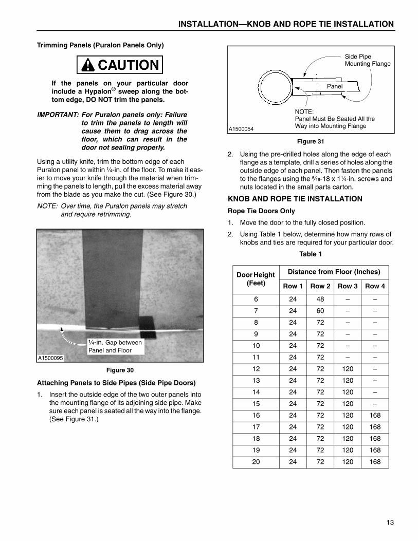
Trimming Panels (Puralon Panels Only)
If the panels on your particular doorinclude a Hypalon® sweep along the bot-tom edge, DO NOT trim the panels.
IMPORTANT: For Puralon panels only: Failureto trim the panels to length willcause them to drag across thefloor, which can result in thedoor not sealing properly.
Using a utility knife, trim the bottom edge of each Puralon panel to within ¹�₄-in. of the floor. To make it eas-ier to move your knife through the material when trim-ming the panels to length, pull the excess material away from the blade as you make the cut. (See Figure 30.)
NOTE: Over time, the Puralon panels may stretchand require retrimming.
Figure 30
Attaching Panels to Side Pipes (Side Pipe Doors)
1. Insert the outside edge of the two outer panels into the mounting flange of its adjoining side pipe. Make sure each panel is seated all the way into the flange. (See Figure 31.)
Figure 31
2. Using the pre-drilled holes along the edge of each flange as a template, drill a series of holes along the outside edge of each panel. Then fasten the panels to the flanges using the ⁵�₁₆-18 x 1¹�₄-in. screws and nuts located in the small parts carton.
KNOB AND ROPE TIE INSTALLATION
Rope Tie Doors Only
1. Move the door to the fully closed position.
2. Using Table 1 below, determine how many rows of knobs and ties are required for your particular door.
Table 1
A1500095
¹�₄-in. Gap betweenPanel and Floor
Door Height (Feet)
Distance from Floor (Inches)
Row 1 Row 2 Row 3 Row 4
6 24 48 – –
7 24 60 – –
8 24 72 – –
9 24 72 – –
10 24 72 – –
11 24 72 – –
12 24 72 120 –
13 24 72 120 –
14 24 72 120 –
15 24 72 120 –
16 24 72 120 168
17 24 72 120 168
18 24 72 120 168
19 24 72 120 168
20 24 72 120 168
A1500054
Side Pipe
NOTE:Panel Must Be Seated All theWay into Mounting Flange
Mounting Flange
Panel
13
INSTALLATION—KNOB AND ROPE TIE INSTALLATION
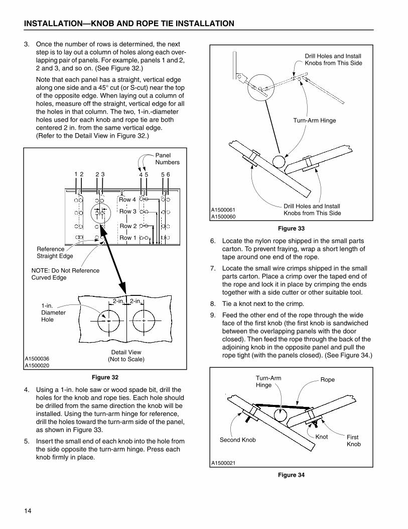
3. Once the number of rows is determined, the next step is to lay out a column of holes along each over-lapping pair of panels. For example, panels 1 and 2, 2 and 3, and so on. (See Figure 32.)
Note that each panel has a straight, vertical edge along one side and a 45° cut (or S-cut) near the top of the opposite edge. When laying out a column of holes, measure off the straight, vertical edge for all the holes in that column. The two, 1-in.-diameter holes used for each knob and rope tie are both centered 2 in. from the same vertical edge.(Refer to the Detail View in Figure 32.)
Figure 32
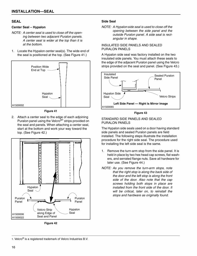
4. Using a 1-in. hole saw or wood spade bit, drill the holes for the knob and rope ties. Each hole should be drilled from the same direction the knob will be installed. Using the turn-arm hinge for reference, drill the holes toward the turn-arm side of the panel, as shown in Figure 33.
5. Insert the small end of each knob into the hole from the side opposite the turn-arm hinge. Press each knob firmly in place.
Figure 33
6. Locate the nylon rope shipped in the small parts carton. To prevent fraying, wrap a short length of tape around one end of the rope.
7. Locate the small wire crimps shipped in the small parts carton. Place a crimp over the taped end of the rope and lock it in place by crimping the ends together with a side cutter or other suitable tool.
8. Tie a knot next to the crimp.
9. Feed the other end of the rope through the wide face of the first knob (the first knob is sandwiched between the overlapping panels with the door closed). Then feed the rope through the back of the adjoining knob in the opposite panel and pull the rope tight (with the panels closed). (See Figure 34.)
Figure 34
A1500036A1500020
1 2 2 3 4 5 5 6
Row 4
Row 3
Row 2
Row 1
Reference
PanelNumbers
1-in.Diameter
2-in.2-in.
Hole
Straight Edge
NOTE: Do Not ReferenceCurved Edge
Detail View(Not to Scale)
A1500060A1500061
Turn-Arm Hinge
Drill Holes and InstallKnobs from This Side
Drill Holes and InstallKnobs from This Side
A1500021
Turn-Arm Rope
Second Knob FirstKnot
Hinge
Knob
14

INSTALLATION—KNOB AND ROPE TIE INSTALLATION
10. To secure the rope tie, tie a knot close to the wide face of the second knob. The rope should be with-out slack with the door fully closed.(See Figure 35 and Figure 36.)
Figure 35
Figure 36
11. To prevent the other end of the rope tie from fraying once it is cut to length, wrap a length of tape around the rope, near the second knot. Then cut the rope tie to length — cutting across the middle of the taped section. Install a crimp over the taped end.(See Figure 37.)
Figure 37
12. Repeat the above steps for each pair of knobs. Fig-ure 38 shows a complete set of knobs with a knot and a crimp at each end of the tie. Figure 39 illus-trates a complete rope tie on both sides of the door.
Figure 38
Figure 39
13. To prevent the Puralon panels from cutting into the rope ties as the door is opened and closed, cut (shave) a slight bevel, about 4 in. long, along the edge of each panel where it makes contact with each rope tie. (See Figure 40.)
Figure 40
A1500005
Panel
Wide Face
Knot
of Knob
A1500062
Correct
Incorrect
Rope Tie MustBe Tight withDoor Closed
A1500063
Knot
Tape
Crimp
A1500097
Knob
Crimp
Rope
A1500041 Left Side Shown — Top View
Side
Rope
Turn-
Knob
Puralon
Knob
Panel
Arm Hinge
Panel
A1500096
Knob
Rope Tie
Cut 4-in.-Long Bevel alongEdge of Panel
15
INSTALLATION—SEAL
SEAL
Center Seal – Hypalon
NOTE: A center seal is used to close off the open-ing between two adjacent Puralon panels.A center seal is wider at the top than it isat the bottom.
1. Locate the Hypalon center seal(s). The wide end of the seal is positioned at the top. (See Figure 41.)
Figure 41
2. Attach a center seal to the edge of each adjoining Puralon panel using the Velcro®1 strips provided on the seal and panels. When attaching a center seal, start at the bottom and work your way toward the top. (See Figure 42.)
Figure 42
Side Seal
NOTE: A Hypalon side seal is used to close off theopening between the side panel and theoutside Puralon panel. A side seal is rect-angular in shape.
INSULATED SIDE PANELS AND SEALED PURALON PANELS
A Hypalon side seal was factory installed on the two insulated side panels. You must attach these seals to the edge of the adjacent Puralon panel using the Velcro strips provided on the seal and panel. (See Figure 43.)
Figure 43
STANDARD SIDE PANELS AND SEALED PURALON PANELS
The Hypalon side seals used on a door having standard side panels and sealed Puralon panels are field installed. The following steps illustrate the installation procedure for the right side seal. The procedure used for installing the left side seal is the same.
1. Remove the turn-arm stop from the side panel. It is held in place by two hex head cap screws, flat wash-ers, and serrated flange nuts. Save all hardware for later use. (See Figure 44.)
NOTE: As you remove the turn-arm stops, notethat the right stop is along the back side ofthe door and the left stop is along the frontside of the door. Also note that the capscrews holding both stops in place areinstalled from the front side of the door. Itwill be critical, later on, to reinstall thestops and hardware as originally found.
1. Velcro® is a registered trademark of Velcro Industries B.V.
A1500002
Position Wide
HypalonSeal
End at Top
A1500006A1500022
Hypalon
Puralon
HypalonVelcro Strip along Edge of
Seal
SealSeal and Panel
PanelPuralonPanel
Left Side Panel — Right Is Mirror ImageA1500065
Hypalon SideVelcro Strips
Sealed PuralonInsulatedSide Panel
Seal
Panel
16
INSTALLATION—SEAL
Figure 44
2. Locate the side seal and attach it to the side panel using the bolting bar and the self-tapping screws provided in the small parts carton. (See Figure 45.) Make sure to position the seal so that the Velcro strip along the back edge is facing the sealed Puralon panel. (See Figure 46.)
Figure 45
Figure 46
3. Drill two ³�₈-in. holes in the side seal. The holes must align with the holes in the side panel that are used for mounting the turn-arm stop. (See Figure 47.)
Figure 47
4. Reattach the turn-arm stop as it was originally found using the saved hardware. Face the rubber bumper on the stop toward the center of the door.(See Figure 44.)
5. Repeat the above procedure for the left side seal.
A1500105
Right Turn-
Hex HeadCap Screw
FlatArm Stop
Right SidePanel
Washer
NOTE: Right Turn-ArmStop along Back Sideof Door. Left Turn-ArmStop along FrontSide of Door.
Serrated Flange Nut
A1500108
Side Seal
Self-TappingScrew
Bolting Bar
SidePanel
A1500042
StandardSide Panel
Side
SealedPuralon
Seal
Panel
Face Velcro Strip on Side Seal towardSealed Puralon Panel
A1500109
Drill ³�₈-in. Holesin Side Seal toLine Up with Holes
SidePanel
Side Seal
in Side Panel
17
INSTALLATION—PANEL CLEANING
FREEZER DOOR SIDE SEAL
NOTE: A Hypalon side seal is used to close off theopening between the side panel and theoutside Puralon panel.
Locate the side seal and attach it to the side panel using the clamp strip and self-tapping screws provided in the small parts carton. (See Figure 48 and Figure 49.)
Figure 48
Figure 49
PANEL CLEANING
Once the panels and seals are in place, clean the pan-els with a general household surface and glass cleaner. Avoid scratching the panels by using a clean, soft cloth.
DOOR SEALING
Caulk the side panels and the head assembly where they meet the wall of the building.
MANUAL BRAKE RELEASE (OPTIONAL ITEM)
If the door is equipped with a manual brake release kit, there will be a cable attached to the brake release han-dle that is located on the end of the motor. Tie the cable out of the way of traffic using a cable clamp or other suitable method.
DEFROST SYSTEM (FREEZER DOOR OPTION)
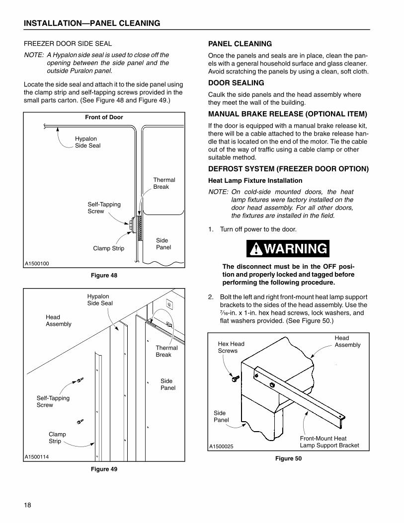
Heat Lamp Fixture Installation
NOTE: On cold-side mounted doors, the heatlamp fixtures were factory installed on thedoor head assembly. For all other doors,the fixtures are installed in the field.
1. Turn off power to the door.
The disconnect must be in the OFF posi-tion and properly locked and tagged beforeperforming the following procedure.
2. Bolt the left and right front-mount heat lamp support brackets to the sides of the head assembly. Use the ⁷�₁₆-in. x 1-in. hex head screws, lock washers, and flat washers provided. (See Figure 50.)
Figure 50
A1500100
Front of Door
Hypalon
Self-Tapping
Clamp Strip
Thermal
Side
Screw
Panel
Break
Side Seal
A1500114
Head
Side
Hypalon
Clamp
Self-TappingScrew
Panel
Strip
Side Seal
Assembly
ThermalBreak
A1500025
Head
Front-Mount HeatLamp Support Bracket
Side
Hex HeadScrews
Assembly
Panel
18

INSTALLATION—DEFROST SYSTEM (FREEZER DOOR OPTION)
3. Install a triangular heat lamp fixture bracket on both ends of each lamp fixture. Use the 10-24 x ³�₄-in. hex head screws, lock washers, and hex nuts provided. (See Figure 51.)
Figure 51
4. Attach the heat lamp fixtures to the front-mount heat lamp angle using the ³�₈-16 x 1-in. hex head screws and serrated flange nuts provided. DO NOT install the lamp bulbs or red sleeves at this time.(See Figure 52.)
Figure 52
5. Install the front-mount heat lamp angle (with fix-tures) to the end of the support brackets that were mounted earlier. Use the ³�₈-in. x 1¹�₄-in. hex head screws and serrated flange nuts provided.(See Figure 53.)
Figure 53
Lamp Fixture Wiring and Bulb Installation
The disconnect must be in the OFF posi-tion and properly locked and tagged beforeperforming the following procedure.
Wire all heat lamp fixtures according to the schematic that was shipped with the control panel, following all state and local codes. The necessary conduit, junction box, and wiring are to be supplied by the owner of the door. Route the wiring from the lamp fixtures to the junc-tion box as shown. (See Figure 54.)
Figure 54
A1500111
Heat Lamp Fixture Bracket
Hex Head
Hex NutLockWasher
Heat LampFixture
Screw
A1500028
Front-Mount
Screw
Heat Lamp
Serrated Flange
Heat Lamp Angle
Nut
Fixture
A1500026
Hex Head
Serrated Flange
Front-MountHeat LampAngle
Screw
Nut
A1500027
Head
Junction
Wiring
Assembly
Box
Heat LampFixture
19
INSTALLATION—DEFROST SYSTEM (FREEZER DOOR OPTION)
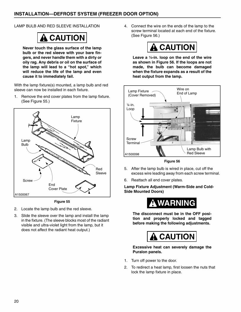
LAMP BULB AND RED SLEEVE INSTALLATION
Never touch the glass surface of the lampbulb or the red sleeve with your bare fin-gers, and never handle them with a dirty oroily rag. Any debris or oil on the surface ofthe lamp will lead to a “hot spot,” whichwill reduce the life of the lamp and evencause it to immediately fail.
With the lamp fixture(s) mounted, a lamp bulb and red sleeve can now be installed in each fixture.
1. Remove the end cover plates from the lamp fixture.(See Figure 55.)
Figure 55
2. Locate the lamp bulb and the red sleeve.
3. Slide the sleeve over the lamp and install the lamp in the fixture. (The sleeve blocks most of the radiant visible and ultra-violet light from the lamp, but it does not affect the radiant heat output.)
4. Connect the wire on the ends of the lamp to the screw terminal located at each end of the fixture.(See Figure 56.)
Leave a ¹�₄-in. loop on the end of the wireas shown in Figure 56. If the loops are notmade, the bulb can become damagedwhen the fixture expands as a result of theheat output from the lamp.
Figure 56
5. After the lamp bulb is wired in place, cut off the excess wire leading away from each screw terminal.
6. Reattach all end cover plates.
Lamp Fixture Adjustment (Warm-Side and Cold-Side Mounted Doors)
The disconnect must be in the OFF posi-tion and properly locked and taggedbefore making the following adjustments.
Excessive heat can severely damage thePuralon panels.
1. Turn off power to the door.
2. To redirect a heat lamp, first loosen the nuts that lock the lamp fixture in place.
A1500067
Lamp
Red
Lamp
Screw
Sleeve
Bulb
Fixture
EndCover Plate
A1500098
Lamp Fixture Wire on
Lamp Bulb with
¼-in.Loop
(Cover Removed)
Red Sleeve
End of Lamp
ScrewTerminal
20

INSTALLATION—DEFROST SYSTEM (FREEZER DOOR OPTION)
3. Direct the heat lamp fixture(s) to aim at the area of the floor where the panels of the door meet the floor. (See Figure 57 through Figure 60.)
Figure 57 and Figure 59 show the correct method for aiming a lamp fixture. Figure 58 and Figure 60 show the incorrect method.
Figure 57
Figure 58
Figure 59
Figure 60
A1500029
Warm-Side Mounted Door
Aim fixture toward
Heat Lamp
Correct Angle to Aim Lamp Fixture
Fixture
area of floor wherePuralon panels meetfloor (allows radiantheat to rise acrossentire face of door).
A1500030
Warm-Side Mounted DoorIncorrect Angle to Aim Lamp Fixture
Damage to panel can
Aiming lamp fixture straight
result if lamp fixture
down will have no affect on
is aimed directly at panel.
defrosting the door.
A1500032
Cold-Side Mounted DoorCorrect Angle to Aim Lamp Fixture
Heat LampFixture
Aim fixture towardarea of floor wherePuralon panels meetfloor (allows warmair to rise acrossentire face of door).
A1500034
Cold-Side Mounted DoorIncorrect Angle to Aim Lamp Fixture
Damage to panelcan result if lampfixture is aimeddirectly at panel.
Aiming lamp fixturestraight down willhave no affect ondefrosting the door.
21
INSTALLATION—DEFROST SYSTEM (FREEZER DOOR OPTION)
Heat Lamp Controls
If your door is equipped with heat lamps, they are con-trolled by the control panel. Refer to the Rytec System 3 Drive & Control Installation & Owner’s Manual.
With the defrost system in the MANUAL mode, the heat lamps will immediately power up. When in the AUTO mode, the heat lamps are operated automatically by the control system. An automatic timer function can be set to periodically cycle the lamps on and off. Placing the defrost system in the OFF mode turns off the lamps and disables the automatic timer function.
Blower Controls
BLOWER SPEED
If your door is equipped with a blower (unheated or heated), the blower fan speed has four modes of opera-tion (OFF, LOW, HIGH, and AUTOMATIC). Refer to the Rytec System 3 Drive & Control Installation & Owner’s Manual.
With the blower switch in the AUTOMATIC position and the door closed, the blower will run at low speed. When the door is open, the blower will operate at high speed. With the blower switch in the HIGH or LOW position, the blower will run at high or low speed regardless of the position of the door.
The blower speed you select (LOW, HIGH, or AUTO-MATIC) will depend on the environmental conditions (temperature, humidity, etc.) of the installation site. Placing the switch in the OFF position will override the control system and prevent the blower from turning on.
BLOWER HEATER
If the blower is equipped with an internal heater (heated blower), the heat level is controlled by the control panel. Refer to the Rytec System 3 Drive & Control Installation & Owner’s Manual.
The standard heated blower has two heating levels. An optional heated blower is available with three heating levels.
The heat level you select will need to be set according to the environmental conditions of the installation site.
Hard-Panel Door
If an optional, hard-panel door is installed with your Rytec Door, the defrost system must be controlled by a limit switch installed on the hard-panel door to prevent heat build-up between the two doors. (“Hard-Panel Door Remote Limit Switch (Mandatory Item if Hard-Panel Door Is Installed)” on page 24.)
If an optional, hard-panel door is installedwith your Rytec Door, a limit switch tooverride the defrost system must beinstalled on the optional door.
When installed in accordance with the schematic that was shipped with the door, the limit switch will allow the defrost system to turn on only when the hard-panel door is in the fully open position.
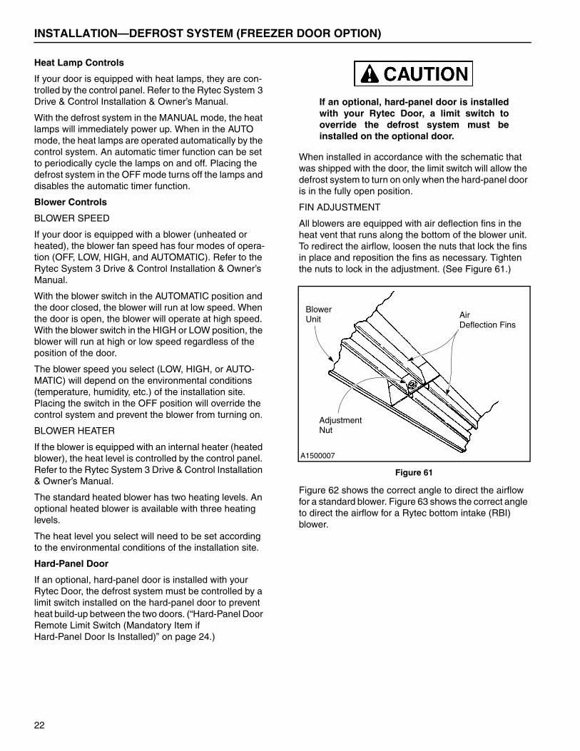
FIN ADJUSTMENT
All blowers are equipped with air deflection fins in the heat vent that runs along the bottom of the blower unit. To redirect the airflow, loosen the nuts that lock the fins in place and reposition the fins as necessary. Tighten the nuts to lock in the adjustment. (See Figure 61.)
Figure 61
Figure 62 shows the correct angle to direct the airflow for a standard blower. Figure 63 shows the correct angle to direct the airflow for a Rytec bottom intake (RBI) blower.
A1500007
BlowerAirUnit
AdjustmentNut
Deflection Fins
22

INSTALLATION—ELECTRICAL SYSTEM
Figure 62
Figure 63
ELECTRICAL SYSTEM
NOTE: Refer to the Rytec System 3 Drive & Con-trol Installation & Owner’s Manual for elec-trical system wiring.
Door Close and Open Limit Position
The door should open and close completely, without traveling beyond the limits in either direction.
Improperly adjusted open and close limitscan result in damage to the drive system.
NOTE: To set the close and open limits, refer tothe Rytec System 3 Drive & Control Instal-lation & Owner’s Manual.
CLOSE LIMIT
1. Turn on the power and close the door.
2. Check the spacing between each door panel. If the door is not closed completely, the leading panels will have a gap between them. If the door is closed too tightly, the rubber bumpers on the turn arms will be compressed. (See Figure 64.)
Figure 64
NOTE: To check if the door has closed too far, per-form the following procedure.
3. With the door closed, turn off the power and manu-ally release the brake. If the door springs back toward the open direction as the brake is released, the door is closing too far and the close limit should be readjusted. Refer to the Rytec System 3 Drive & Control Installation & Owner’s Manual.
A1500154
Cold-Side Mounted DoorCorrect Angle to Aim Standard Blower
StandardBlower
Aim heat vent finstoward area of floorwhere Puralon panelsmeet floor.
A1500153
Cold-Side Mounted DoorCorrect Angle to Aim RBI Blower
Rytec BottomIntake Blower(RBI)
Direct heat ventfins straight downto ensure airintake pulls returnair across entireface of panel.
A1500004
Turn Arm Turn Arm
Bumper Puralon
Hypalon SealPanelPuralon
Panel
23
INSTALLATION—ELECTRICAL SYSTEM
OPEN LIMIT
1. Turn on the power and open the door.
2. Check that the door is in the fully open position. If the door is not open all the way, the leading panels will be inside the door opening. If the door is open too far, the rubber bumpers between the turn arms will be compressed. (See Figure 65.)
Figure 65
NOTE: To check if the door has opened too far,perform the following procedure.
3. With the door open, turn off the power and manually release the brake. If the door springs back toward the close direction as the brake is released, the door is opening too far and the open limit should be readjusted. Refer to the Rytec System 3 Drive & Control Installation & Owner’s Manual.
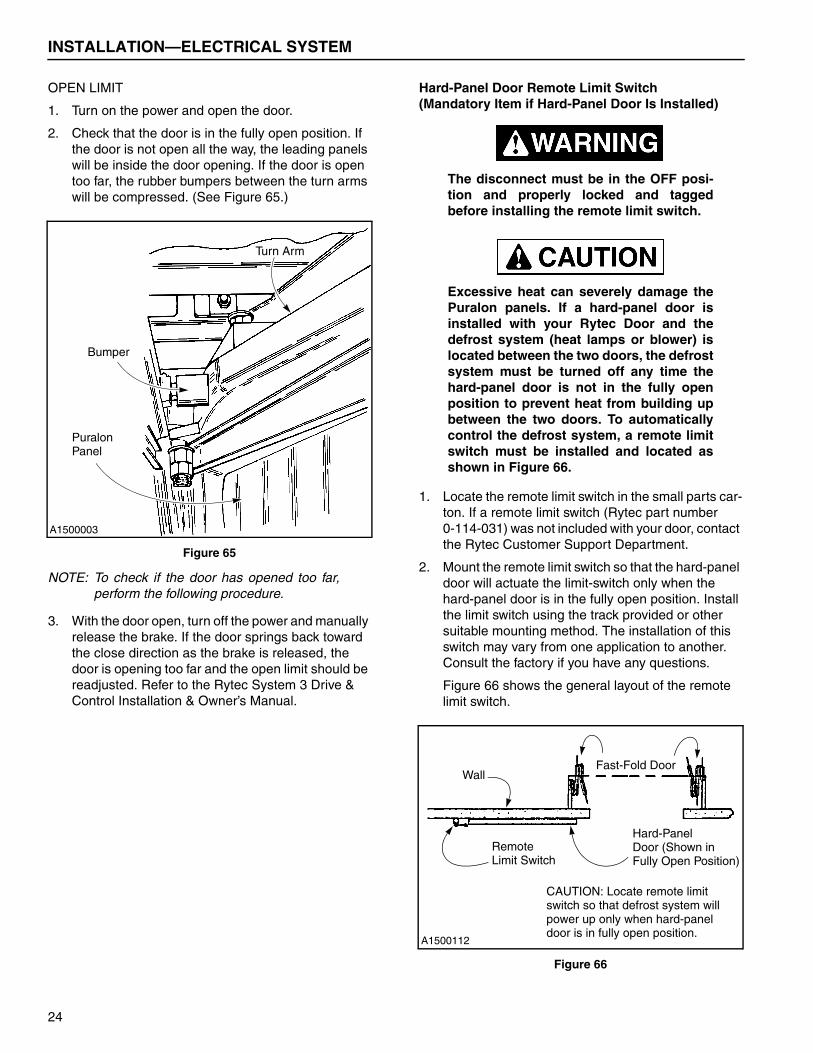
Hard-Panel Door Remote Limit Switch (Mandatory Item if Hard-Panel Door Is Installed)
The disconnect must be in the OFF posi-tion and properly locked and taggedbefore installing the remote limit switch.
Excessive heat can severely damage thePuralon panels. If a hard-panel door isinstalled with your Rytec Door and thedefrost system (heat lamps or blower) islocated between the two doors, the defrostsystem must be turned off any time thehard-panel door is not in the fully openposition to prevent heat from building upbetween the two doors. To automaticallycontrol the defrost system, a remote limitswitch must be installed and located asshown in Figure 66.
1. Locate the remote limit switch in the small parts car-ton. If a remote limit switch (Rytec part number 0-114-031) was not included with your door, contact the Rytec Customer Support Department.
2. Mount the remote limit switch so that the hard-panel door will actuate the limit-switch only when the hard-panel door is in the fully open position. Install the limit switch using the track provided or other suitable mounting method. The installation of this switch may vary from one application to another. Consult the factory if you have any questions.
Figure 66 shows the general layout of the remote limit switch.
Figure 66
Bumper
Puralon
Turn Arm
Panel
A1500003
A1500112
Fast-Fold Door
Hard-PanelRemoteLimit Switch
Door (Shown in
Wall
CAUTION: Locate remote limitswitch so that defrost system will power up only when hard-paneldoor is in fully open position.
Fully Open Position)
24

INSTALLATION
FINAL CHECKS
NOTE: Check all of the following door compo-nents and systems once the door panelhas been cycled at least 20 times.
Side Panels: Check that side panels are plumb and square and that all anchor bolts are secure and tight.
Head Assembly: Check that all mounting hardware is in place and tight.
Door Panels: Check that all door panels are installed properly, hanging straight, and travel smoothly as described in “PANELS” on page 10. Make sure all hard-ware is in place and tight.
The panels should be kept trimmed to within ¹�₄-in. of the floor as described in “Trimming Panels (Puralon Panels Only)” on page 13. Because the panels can stretch over time, failure to keep them trimmed to length could result in a door that seals poorly.
Knobs and Rope Ties: All knobs and rope ties should be installed correctly as described in “Knob and Rope Tie Installation” on page 13.
Seals: All seals should be installed correctly, as described in “SEAL” on page 16.
Side Pipes (Non-Sealed Panel Doors Only): Both side pipes should be installed with a roll pin as shown in Figure 23. The outer Puralon panels should be bolted to the side pipes.
Close and Open Limits: Adjusted properly. Side-to-side travel of the door should be as described in “Door Close and Open Limit Position” on page 23.
Motor: Check that the door travels in the proper direc-tion when the button is pressed.
Timers: Automatic timers must be set to ensure that the door closes properly, as described in the Rytec System 3 Drive & Control Installation & Owner’s Manual.
Activators: Operate as specified by manufacturer.
Caulk: Be sure that the side panels and head assembly are caulked where they meet the wall of the building.
Freezer Doors: Check the defrost system for normal operation and adjust as required. If an optional hard-panel door is used, verify that the remote limit switch allows the defrost system to power up only when the hard-panel door is in the fully open position. Check all controls for proper operation.
25

NOTES
26