Embed Size (px)
Citation preview

Fast Discrete Intersection Detection for ClothPenetration Resolution
Juntao YeInstitute of Automation
Chinese Academy of SciencesBeijing, China
Email: [email protected]
Timo R. NybergDept. of Industrial Eng. and Management
School of Science, Aalto UniversityEspoo, Finland
Email: [email protected]
Gang XiongCloud Computing Center
Chinese Academy of SciencesDongguan, China
Email: [email protected]
Abstract—Penetrations are often unavoidable in modeling clothor other deformable surfaces. It could exist as an initial configu-ration or show up in the middle of a dynamics simulation process.We present a new method for resolving such penetrations. To beadapted to a wide range of applications, this method is basedon history-free discrete intersection detection (DID). It is alsoorientation-free as it does not assume any front- and back- faceidentification. Our method relies on dynamic repulsive normal(DRN) to compute proper displacements to relocate vertices tobe intersection-free. First, intersection contours are constructedand classified, followed by a global analysis of the collisionconfigurations. Then for some types of configurations, penetrating(illegal) regions are identified using a heuristic paradigm “smallregion is illegal”. For those surfaces having identifiable illegalregions, proper displacements for incorrectly configured verticesare computed using DRN. For those configurations that do notclearly define legal/illegal regions, displacements are designedto push one mesh to the boundary of the other. The proposedmethod can also be used in the context of time-dependent simu-lation of complex deformable surfaces, making it an competitivealternative to the popular CCD-based approach.
I. INTRODUCTION
The majority of cloth and other soft body modeling systemsadopt continuous collision detection (CCD) to predict impend-ing collisions, then attempt to prevent them from happeningby altering the particles’ velocities. The success of CCD-based response relies on a hard constraint: an intersection-free state for not only the initial configuration but also thestarting of every time interval in the simulation. There arealso applications in which an intersection-free initial state isimpossible, or the simulation context is subject to externalconstraints forcing the cloth into illegal states for a number ofconsecutive steps. Moreover, although every collision eventcarries a time tag in CCD, they are often neglected, asresolving all the events strictly according to their time ordercan be too slow to halt the simulation. Thus simultaneousresponse is often adopted.
Contrast to collision prevention methods, collision repairstrategy allows penetrations to occur but try to detect and fixthem. It employs discrete intersection detection (DID) so itis history-free. DID is expected to be more efficient for twopoints: bounding volumes are more tight-fitting and no cubicsolver is needed. For most cloth meshes there is no way todefine inside/outside, this strategy is also orientation-free. So
Fig. 1: Resolving five intertwined sheets. Three of them have 2, 754particles each, and the flat one has 6, 561 and the other has 1, 681.
far it has largely been used as a complementary mechanismto CCD-based framework.
We envision a DID-based collision correction framework,not only for untangling penetrations, but also as an alternativeto the popular CCD-based approaches. However, designing apurely history-free and orientation-free response algorithm isoften an ambiguous and ill-defined problem (see Fig 2 for suchan example). Recall that in CCD-based response, plane normalplays an important role in detecting if a geometric primitive(edge or vertex) is crossing a specific plane, and is also crucialin defining repulsion force or impulse to stop the approaching.The proper normal direction is so picked that it is consistentwith the negative approaching velocity. That is to say thesurface orientation is derived from the history information. Yethistory information such as velocity is unavailable in DID, soheuristic has to be resorted to identify the penetration regions.Instead of imposing a hard constraints as in CCD, we onlymake an assumption which is easily satisfied: most of a surfaceis of legal status at any time of the simulation.
This paper extends the previous correction-based workby introducing dynamic repulsive normal (DRN). We firstperform an efficient discrete intersection detection (§3). Thenthe intersection contours are constructed (§4.1), and classifiedto identify the penetrating/illegal regions (§4.2) by using aheuristic paradigm “small region is illegal”. For those mesheshaving identifiable illegal regions, proper correcting displace-ments are computed for incorrectly configured vertices usingDRN (§5.1). For those configurations that do not clearly definelegal/illegal regions, displacements are designed to push onemesh to the boundary of another one (§5.1). In both cases,the displacements are first computed per E-F (edge-face) pair
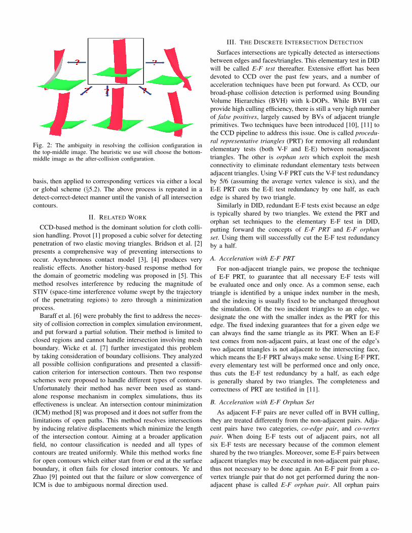
Fig. 2: The ambiguity in resolving the collision configuration inthe top-middle image. The heuristic we use will choose the bottom-middle image as the after-collision configuration.
basis, then applied to corresponding vertices via either a localor global scheme (§5.2). The above process is repeated in adetect-correct-detect manner until the vanish of all intersectioncontours.
II. RELATED WORK
CCD-based method is the dominant solution for cloth colli-sion handling. Provot [1] proposed a cubic solver for detectingpenetration of two elastic moving triangles. Bridson et al. [2]presents a comprehensive way of preventing intersections tooccur. Asynchronous contact model [3], [4] produces veryrealistic effects. Another history-based response method forthe domain of geometric modeling was proposed in [5]. Thismethod resolves interference by reducing the magnitude ofSTIV (space-time interference volume swept by the trajectoryof the penetrating regions) to zero through a minimizationprocess.
Baraff et al. [6] were probably the first to address the neces-sity of collision correction in complex simulation environment,and put forward a partial solution. Their method is limited toclosed regions and cannot handle intersection involving meshboundary. Wicke et al. [7] further investigated this problemby taking consideration of boundary collisions. They analyzedall possible collision configurations and presented a classifi-cation criterion for intersection contours. Then two responseschemes were proposed to handle different types of contours.Unfortunately their method has never been used as stand-alone response mechanism in complex simulations, thus itseffectiveness is unclear. An intersection contour minimization(ICM) method [8] was proposed and it does not suffer from thelimitations of open paths. This method resolves intersectionsby inducing relative displacements which minimize the lengthof the intersection contour. Aiming at a broader applicationfield, no contour classification is needed and all types ofcontours are treated uniformly. While this method works finefor open contours which either start from or end at the surfaceboundary, it often fails for closed interior contours. Ye andZhao [9] pointed out that the failure or slow convergence ofICM is due to ambiguous normal direction used.
III. THE DISCRETE INTERSECTION DETECTION
Surfaces intersections are typically detected as intersectionsbetween edges and faces/triangles. This elementary test in DIDwill be called E-F test thereafter. Extensive effort has beendevoted to CCD over the past few years, and a number ofacceleration techniques have been put forward. As CCD, ourbroad-phase collision detection is performed using BoundingVolume Hierarchies (BVH) with k-DOPs. While BVH canprovide high culling efficiency, there is still a very high numberof false positives, largely caused by BVs of adjacent triangleprimitives. Two techniques have been introduced [10], [11] tothe CCD pipeline to address this issue. One is called procedu-ral representative triangles (PRT) for removing all redundantelementary tests (both V-F and E-E) between nonadjacenttriangles. The other is orphan sets which exploit the meshconnectivity to eliminate redundant elementary tests betweenadjacent triangles. Using V-F PRT cuts the V-F test redundancyby 5/6 (assuming the average vertex valence is six), and theE-E PRT cuts the E-E test redundancy by one half, as eachedge is shared by two triangle.
Similarly in DID, redundant E-F tests exist because an edgeis typically shared by two triangles. We extend the PRT andorphan set techniques to the elementary E-F test in DID,putting forward the concepts of E-F PRT and E-F orphanset. Using them will successfully cut the E-F test redundancyby a half.
A. Acceleration with E-F PRT
For non-adjacent triangle pairs, we propose the techniqueof E-F PRT, to guarantee that all necessary E-F tests willbe evaluated once and only once. As a common sense, eachtriangle is identified by a unique index number in the mesh,and the indexing is usually fixed to be unchanged throughoutthe simulation. Of the two incident triangles to an edge, wedesignate the one with the smaller index as the PRT for thisedge. The fixed indexing guarantees that for a given edge wecan always find the same triangle as its PRT. When an E-Ftest comes from non-adjacent pairs, at least one of the edge’stwo adjacent triangles is not adjacent to the intersecting face,which means the E-F PRT always make sense. Using E-F PRT,every elementary test will be performed once and only once,thus cuts the E-F test redundancy by a half, as each edgeis generally shared by two triangles. The completeness andcorrectness of PRT are testified in [11].
B. Acceleration with E-F Orphan Set
As adjacent F-F pairs are never culled off in BVH culling,they are treated differently from the non-adjacent pairs. Adja-cent pairs have two categories, co-edge pair, and co-vertexpair. When doing E-F tests out of adjacent pairs, not allsix E-F tests are necessary because of the common elementshared by the two triangles. Moreover, some E-F pairs betweenadjacent triangles may be executed in non-adjacent pair phase,thus not necessary to be done again. An E-F pair from a co-vertex triangle pair that do not get performed during the non-adjacent phase is called E-F orphan pair. All orphan pairs

constitute orphan set, which is a subset of the E-F tests fromadjacent triangle pairs. This relationship is similar to the V-Fand E-E tests from adjacent pairs in CCD, in which Tang et al.[11] introduce an optimization algorithm based on the workof Govindaraju et al. [12].
Although V-F orphan pairs and E-E orphan pairs exist in aclosed mesh for CCD, E-F orphan pairs only appear in mesheswith boundary. In a closed mesh, all the E-F tests can beexecuted in non-adjacent phase, so no E-F test is needed inthe adjacent phase. In other words, the edge E in an E-Forphan pair is a boundary edge. This makes the E-F orphanset different from V-F and E-E orphan sets in CCD, in that E-Ftest can not happen between co-edge triangle pairs. Moreover,only an edge that is not incident to the shared vertex will bepart of an E-F orphan pair. That is to say, for a co-vertextriangle pair, at most two E-F orphan pairs can be formed.However, E-F orphan pair does not always exist in a co-vertextriangle pair. It is sufficient to identify all E-F orphan set in apre-processing step. First, all the co-vertex triangle pairs areconstructed. Then for every pair, only the edge that is notincident to the common vertex has potentials to intersect withthe other triangle, so only two edges from the pair need to betested.
IV. INTERSECTION CONTOUR CONSTRUCTION ANDCLASSIFICATION
A. Contour Construction
The above DID process only outputs a set of E-F inter-sections. Many collision resolving algorithms [6], [8], [7], [9]rely on the topology of the intersection contours to determinethe legal/illegal regions, so a robust intersection contour recon-struction algorithm is necessary. The construction is performedin a bottom-up manner in four stages, as will be detailed inthe following.
Register intersection points. For every E-F intersectionpoint, we register it to its host triangles. Each point willgenerally has three host triangles, including the two adjacenttriangles incident to the intersecting edge and the correspond-ing intersecting face in this E-F pair. If the edge is on theboundary, there are only two host triangles. As a result, everytriangle has at least two E-F intersection points.
Construct in-face poly-lines. Using the PRT and orphanset techniques imposes a little trouble for intersection contourconstruction. Without using such tricks, each intersecting F-F pair produces an intersection segment, thus concatenatingall these segments head-to-tail will recover the whole contourof two intersecting meshes. With the acceleration techniques,not all six E-F tests are executed in each F-F test, thus wewill not get a list of line segments immediately. Instead,we are end up with a set of E-F intersection points withoutconnectivity information. For each face, there may be multipleintersection points registered to it. With the concept of hosttriangle for every intersection point, two conditions must besatisfied simultaneously if two intersection points in one faceare to be connected:
• Two intersection points have two common host triangles.
• None of the two common host triangles is adjacent to theintersecting edge.
Constructing global contours. After all the in-face poly-lines for every single triangle are constructed, these poly-linesmust be further connected to form global contours. This isdone via a depth-first traversal of every contour. We have everattempted to do it via width-first traversal with the help ofBVH, but found it to be less efficient.
Group end-vertices. Vertices of the intersecting edgesalong a contour are divided into two groups, one group isin penetrating positions and the other is in valid position. Anedge could intersect multiple faces at one time, thus havingmore than one intersection points. Odd number of intersectionsimplies the two end vertices belong to separate groups.
B. Determining Legal/illegal Regions
The success of the global intersection analysis depends onthe classification of the contour. We follow the classificationcriterion given in [7], as shown in Figure 3. The top row showsthe collision configurations, and the bottom row shows thecontours drawn on each (part) of the mesh. This classificationis applicable as long as the cloth surface is a 2-manifold,whether it is closed or with boundaries. Cases (d) (e) (f) (g)have loop vertices, thus they only occur in self-collision. Theterm loop-vertex was coined in [6] to refer to the commonvertex shared by two intersecting adjacent triangles. Contoursfold back onto themselves after reaching a loop vertex, so it isoften helpful to unfold such contours for classification. Thereare five types of contours:
• CL: closed curve; no loop-vertex.• BB: open; both ends on boundary; no loop-vertex.• BLI: one end on boundary, the other inside; one loop-
vertex.• BI: one end on boundary, the other inside; no loop-vertex.• II: open; both ends inside; no loop-vertex.
In a collision configuration, the most common contour pairsare of types CL/CL, BB/II and BI/BI. Some configurationscontaining loop-vertex do not lead to a pair of contours, butone single contour of type CL or BLI. Figure 3 (d) and (g)are such examples. Note that a BB contour usually comesalong with an II contour. Very rarely is the case that a BB canalso correspond to a BI or BB contour. These configurations(BB/BI and BB/BB) are unstable due to boundary-boundaryintersection. Depending on how the round-off error is handledin the E-F test, they are often classified to either BB/II orBI/BI. For the same reason, BLLB is another unstable contourand is treated as two BLI contours for handling.
Of the five contour types, CL and BB were defined in [7]as partitioning contours, i.e. they partition a mesh into twocomponents. However, we find it is true for BB contour onlyif the mesh has one boundary. BB contours in multi-boundarymeshes (e.g. cylindrical surface) are more complicated tohandle and will be discussed in §7. For now, we assume themesh has at most one boundary. Type II always corresponds toBB in which the illegal region can be identified, then II contour

(a) (b) (c) (d) (e) (f) (g)
Fig. 3: Contours classification. Loop vertices are marked on the contours. (a) CL/CL pair. (b) BB/II pair. (c) BI/BI pair. (d) Loop-loopcontour is unfolded to one CL contour. (e) closed contour with a single loop vertex is split to CL/CL pair. (f) The CROSS is split to BB/IIpair. (g) The unfolded BLI contour. Images (e)(f)(g) courtesy of Wicke et al.
will diminish automatically along with the diminishing of BB.BI always corresponds to BI, and the BI/BI configuration isresolved by pushing one mesh to the boundary of anothermesh, as will be detailed in §V-A.
It was proposed in [7] that BLI can be treated as apartitioning contour by construct a cone and flatten it. As loop-vertex occurs so rarely and creating a collision scene with aloop-vertex is not easy, we have no chance to validate theeffectiveness of their method. And also please note that noneof the examples in this paper involves any loop-vertex, andwe focus on the first three penetration cases of Figure 3.
With the paradigm “small is illegal”, the small regiondelimited by CL, BB or BLI is regarded as on the wrongside. It is possible that a mesh has multiple contours and ispartitioned into more than two components. A fact is that thetwo components on the different sides of a contour alwayshave opposite legal/illegal status. In the global analysis, thesecomponents are divided into two groups and their summedareas are compared. The flood-fill algorithm were typicallyused to find the smaller region on a partitioned mesh in theliterature.
V. UNTANGLING WITH POSITION DISPLACEMENT
A. The Dynamic Repulsive Normals
In dynamics simulation, two triangles are allowed to beclose enough but should never penetrate. To fix the illegalstatus of penetration, the simplest scheme is to re-locatedthe two triangles to an intersection-free configuration. Surfacenormals play a very important role in bouncing back thecolliding geometric primitives. A polygonal mesh, with clearlydefined normal directions to denote inside/outside, can becalled oriented surface. For untangling two oriented surfaces,two factors are considered in developing a scheme. First,one mesh ought to be pushed along the “outside-pointing”normal direction of the other mesh. Second, the length ofthe intersection contour should be reduced, ultimately leadingto a complete disappearance. The task of untangling twointersecting meshes can be broken down into separating aseries of E-F intersections. In a collision configuration shownin Figure 4, edge e, shared by two green triangles, intersects a
nr
r1 r2
B1 e B2
A2A1
(a)
r1r1 r1
B0
B1 e B2
A
(b)
Fig. 4: (a) BB/II configuration where green mesh B is partitionedby the intersection contour. The DRN nr is up for face A1. (b) BI/BIconfiguration where the intersection contour does not partition eithermeshes.
red triangle in mesh A. We denote r̂1 and r̂2 two unit vectorson the intersection contour, originated from the intersectionpoint. Let us temporarily suppose that the normal vector nr
unambiguously designates the outside direction of mesh A.According to the above discussion, the displacement appliedto e for separation has two components: one along nr topush it outside of mesh A, and the other within the planeof A to shorten the length of the contour. The direction of thedisplacement is thus defined as
de = n̂r + λ(r̂1 + r̂2). (1)
nr is called the repulsive normal, to differentiate from normalsfor the rendering purpose. The effect of λ(r̂1 + r̂2) is tostraighten the contour until r̂1 and r̂2 become collinear. Toavoid over-shooting, we choose small value: λ = 0.1, for thein-plane component. The small λ also decreases the possibilityof moving the contour to be stuck at a local minima in thecase of concave surfaces.
Now that the direction of nr in Equ 1 has to determined.It could be any of the two opposite directions perpendicularto a triangle, but a wrong choice will simply push thecolliding geometries further in the wrong side. Naively usingthe rendering normal of a face as its nr does not work formany circumstances. For open surfaces (i.e. surfaces withboundaries), there is no way to define inside/outside, and other“invading” objects could come from either side. Even for a

closed surface, if it involves self-collision, using the outside-pointing render normal as nr in Equ 1 is unsafe. Moreover, ifa polygonal mesh is penetrated at more than one spots by otherobjects, each penetration region has its own repulsive normal.Repulsive normal for a region could also vary from time totime, along with changes of the collision configurations. Sinceit is difficult to foresee the dynamic behavior of deformablesurfaces, pre-setting the repulsive normals is impossible. Wethus introduce the concept of dynamic repulsive normals(DRN), which implies that direction of nr is determined on-the-fly and always has the tendency to push any invadingobjects back to where they came from.
The DRN is set for the face of an E-F intersection, andpoints to the side that the legal region of the other mesh residesin. In the configuration of Figure 4(a), the contour is of typeBB for the green mesh and type II for the red mesh. Thegreen mesh is partitioned and the top part is treated as legal.To resolve the e-A1 intersection, the DRN for A1 is set to pointup and the displacement vector applied to edge e is computedvia Equ 1. Note there is no need to set DRN for face A2 asit does not involve any E-F intersection.
If a contour pair is of type BI/BI, as shown in Figure 4(b),no mesh is partitioned thus the DRN is undetermined. In thiscase the DRN vector is set to zero, contributing nothing to thedisplacement vector de. To resolve the E-F intersection, theedge is pushed towards the boundary of the other mesh. Of thetwo in-plane vectors r̂1 and r̂2 for an intersecting edge, froma bookkeeping point of view r̂1 is picked this way: travelingin the direction of every r̂1 along the contour will arrive atthe boundary of the other mesh. Then Equ.1 degenerates to
de = r̂1. (2)
To conserve the momentum of the whole system, once a vectorde is computed, either via Equ 1 or Equ 2, −de is introducedand applied to the corresponding face. This works as a pair ofaction and reaction forces which are equal but opposite.
Although neither Equ 1 nor Equ 2 is applicable to edgesalong a type II contour, it is not a concern. As in Figure 4(a),the type II contour in mesh A comes together with theBB contour in mesh B, and the DRN for faces in B areundetermined so vector de for intersecting edges of mesh Acannot be computed. Fortunately face A1 receives −de fromedge e of mesh B, thus the intersection can still be untangled.
B. Applying the Displacement Vectors
Collision response is performed by enforcing the collisionconstraints through position corrections distributed on meshvertices. After one pass of correction, intersection detectionis perform on the newly positioned meshes, and do anotherpass of response if needed, and so on in an iterative manner.[8] proposed a scheme for applying displacement vectors.Vectors de and −de are distributed as position changes tocorresponding vertices. A vertex pi is usually shared bymultiple intersecting edges or faces, thus receives multiplecontributions: dpi =
∑±dej . The magnitude of the position
correction vector has to be carefully chosen. Small value
means large number of iterations needed for a completeresponse. Large size could easily crash the simulation, asdynamics simulator is vulnerable to brutal position or velocitychanges. A scaled arctangent function is adopted to calcu-late the actual magnitude, so the final position correction ish0
|dpi|√
|dpi|2+g2
0
d̂pi , where g0 defines a progressive slope of
the function, and d̂pi is unit vector. [8] also suggested aglobal scheme that sums up all local corrections and thenuniformly apply it to all involved vertices. That scheme isusually converges faster.
VI. APPLICATIONS AND RESULTS
To test the effectiveness of proposed method, we run variousexamples on a single thread of a 2.13GHz Intel Xeon CPU.
A. Garment Fitting
Garment fitting is to “dress” a human model with anexisting garment model. The fitting process may restrict thedeformation to be subject to physical simulation or just withinthe geometric domain. We show an example of the latter casein Fig 5. Two layers of clothes are dressed on a lady, and thepenetrations exist between shirt and pants, as well as shirt/bodyand pants/body. They are resolved according to specified ease-of-allowance.
Fig. 5: Garment fitting starts with an initial penetration state.
B. Dynamics Simulation
Fig. 6: Four sheets, each modeled by 6,561 particles, fall on a cowmodel.
Fig. 7: Simulation of a sheet of 6,561 particles falling on spikes.
The proposed framework has been integrated into a clothsimulator. Figure 1 shows an example of untangling multiple

Fig. 8: Simulation of a sheet of 6,561 particles interacting withmoving spikes.
intertwined sheets. The initial state consists of different typesof collision configurations (e.g. BB/II and BI/BI), and theyall have been resolved simultaneously in a reasonable manner.Note resolving the BB/II intersection (between the verticalgreen sheet and the horizontal one) is challenging as theposition adjustments need to counteract the gravity. This isalso one of several configurations that cannot be resolved in[8]. Figure 6 demonstrates four sheets falling on a cow model.This example starts with a collision-free state, and resolvesall penetrations until collision-free at each simulation step.It involves not only solid/cloth collisions but also extensivecloth/cloth collisions. Figure 7 and 8 highlights our method’sability to handle sharp geometric features. A sheet interactswith a bed of many spikes, with each spike being representedby four triangles. We tested three different scenarios: a flatsheet falling down onto the spikes, initial penetrations beingresolved, and moving the spikes with the sheet covering them.The DID and the response algorithm works robustly and thesimulated result is free of penetration.
TABLE I: Performance data for examples in Fig.1, 6 , 7 and 8.
Fig. #vertices sim. exec.cloth/solid dura. time
Fig 1 16.5k/0 4.4s 9,068sFig 6 26.2k/6.2k 6.4s 9,171sFig 7 6.5k/1.7k 3.3s 1,241sFig 8 6.5k/1.7k 6.3s 4,511s
Table I shows the computation time for these examples. Wehave witnessed that majority of the penetrations were resolvedin no more than ten detect-correct-detect iterations. As shownin previous experiments, the workload of ten rounds of DID isequal to one CCD. Therefore we believe using the proposedmethod beats the popular CCD based collision response inthese experiments.
VII. CONCLUSION
We have presented a DID-based response to untangle exist-ing penetrations. When used in context of simulating complexdeformable surfaces, it is a competitive alternative to thepopular CCD-based approach. The core of the method is todynamically specify repulsive normal directions. Please beadvised in many circumstances surface orientation is eitherexplicitly given or implied in the context (e.g. closed surfaces),and we should not be blind to that. Taking advantage ofpredefined repulsive normals will save great effort on contourconstruction and the legal/illegal determination.
An obvious advantage of DID-based over CCD-based ap-proach is that simulator can tolerate the existence of insignifi-cant penetrations at each step, as also being highlighted in [8].In real production, the artist can opt, in some designated steps,for incomplete response, as long as the intersecting regions donot expand too much and the rendered images do not sufferfrom visual artifacts.
Limitations. The proposed method also has several limita-tions. One major problem is that we did not give an effec-tive solution to handle intersection contours containing loop-vertices. Another problem is that the BB contour partitions asurface only if the surface has one boundary. Some modelsin real production (e.g. T-shirt) have multiple boundaries, andthe BB contour is no longer a partition contour. Several trickscan be adopted to avoid dealing with the BB case. Due tothe absence of sophisticated friction and contact handling inour simulator, applying the proposed method to simulate morecomplex scenes like clumped cloth involving massive self-collisions is not easy at this moment. This certainly will be adirection of our future work.
ACKNOWLEDGMENT
This work is supported by NSF China under thegrants #61379096, #61233001, and Finnish TEKESs projectSoMa2020: Social Manufacturing (2015-2017).
REFERENCES
[1] X. Provot, “Collision and self-collision handling in cloth model dedi-cated to design garments,” in EG Workshop on Computer Animation andSimulation, 1997, pp. 177–189.
[2] R. Bridson, R. Fedkiw, and J. Anderson, “Robust treatment of collisions,contact and friction for cloth animation,” ACM Trans. Graph., vol. 21,no. 3, pp. 594–603, 2002.
[3] D. Harmon, E. Vouga, B. Smith, R. Tamstorf, and E. Grinspun, “Asyn-chronous Contact Mechanics,” ACM Trans. Graph., vol. 28, no. 3, 2009.
[4] S. Ainsley, E. Vouga, E. Grinspun, and R. Tamstorf, “Speculative parallelasynchronous contact mechanics,” ACM Trans. Graph., vol. 31, no. 6,pp. 151:1–151:8, 2012.
[5] D. Harmon, D. Panozzo, O. Sorkine, and D. Zorin, “Interference awaregeometric modeling,” ACM Trans. Graph., vol. 30, no. 6, pp. 137:1–137:10, 2011.
[6] D. Baraff, A. Witkin, and M. Kass, “Untangling cloth,” ACM Trans.Graph., vol. 22, no. 3, pp. 862–870, 2003.
[7] M. Wicke, H. Lanker, and M. Gross, “Untangling cloth with boundaries,”in Proc. of Vision, Modeling, and Visualization, 2006, pp. 349–356.
[8] P. Volino and N. Magnenat-Thalmann, “Resolving surface collisionsthrough intersection contour minimization,” ACM Trans. Graph., vol. 25,no. 3, pp. 1154–1159, 2006.
[9] J. Ye and J. Zhao, “The intersection contour minimization method foruntangling oriented deformable surfaces,” in Proc. Symp. ComputerAnimation, 2012, pp. 311–316.
[10] S. Curtis, R. Tamstorf, and D. Manocha, “Fast collision detectionfor deformable models using representative-triangles,” in Proc. Symp.Interactive 3D Graphics and Games, 2008, pp. 61–69.
[11] M. Tang, S. Curtis, S.-E. Yoon, and D. Manocha, “ICCD: Interac-tive continuous collision detection between deformable models usingconnectivity-based culling,” IEEE Transactions on Visualization andComputer Graphics, vol. 15, no. 4, pp. 544–557, 2009.
[12] N. K. Govindaraju, D. Knott, N. Jain, I. Kabul, R. Tamstorf, R. Gayle,M. C. Lin, and D. Manocha, “Interactive collision detection betweendeformable models using chromatic decomposition,” in SIGGRAPH,2005, pp. 991–999.