Embed Size (px)
Citation preview

FAMU Student Affairs Center for Access and Student Success
Advanced Schematic Design
May 27, 2016
BRFM-337
Index of Sheets
A1.1 Existing Site
A1.2 Survey
A1.3 Building Foot Print
A1.4 Existing Elevation to Remain
A1.5 New Ground Floor Plan
A1.6 New Mid-Level Floor Plan
A1.7 New Top Level Floor Plan
A1.8 New Front Rendering
A1.9 Courtyard Rendering
A1.10 Building Section
A1.11 Building Section
A1.12 Wall Sections
A1.13 Submission Checklist
A1.14 Checklist, Schedule and Codes
A1.15 Project Budget
A1.16 Project Narrative
A1.17 Project Narrative
A1.18 Existing Elements to Salvage
A1.19 Department of State Review

FA
MU
Stu
de
nt
Aff
air
s C
en
ter
for
Ac
ce
ss
an
d S
tud
en
t S
uc
ce
ss
Ad
van
ce
d S
ch
em
ati
c D
esig
n M
ay
27
, 2
01
6
A1.1
Existing Site

FA
MU
Stu
de
nt
Aff
air
s C
en
ter
for
Ac
ce
ss
an
d S
tud
en
t S
uc
ce
ss
A1.2
Survey
Ad
van
ce
d S
ch
em
ati
c D
esig
n M
ay
27
, 2
01
6

FA
MU
Stu
de
nt
Aff
air
s C
en
ter
for
Ac
ce
ss
an
d S
tud
en
t S
uc
ce
ss
A1.3
Existing Building Foot Print
Existing building to be
demolished
Portion of existing front
elevation to remain and be
incorporated into new
building – See Sheet A1.4
for Elevation
Line of new building footprint
Ad
van
ce
d S
ch
em
ati
c D
esig
n M
a 2
7, 2
01
6

FA
MU
Stu
de
nt
Aff
air
s C
en
ter
for
Ac
ce
ss
an
d S
tud
en
t S
uc
ce
ss
A1.4
Existing Elevation to Remain
Ad
van
ce
d S
ch
em
ati
c D
esig
n M
ay
27
, 2
01
6
Existing Façade to Remain
New and Dormers Roof to Match
Existing
Existing Stair and Porch to RemainExisting Building to be Demolished

FA
MU
Stu
de
nt
Aff
air
s C
en
ter
for
Ac
ce
ss
an
d S
tud
en
t S
uc
ce
ss
A1.5
New Ground Floor Plan
Ad
van
ce
d S
ch
em
ati
c D
esig
n M
ay
27
, 2
01
6
A1.10
A1.11
Department of Enrollment
Management
2805 nsf
Undergraduate
Admissions
1476 nsf
Enrollment
1410 nsf
New Student
Orientation
4668 nsf
Financial Aid
Department of Student
Development
2436 nsf
Counseling
Services
1320 nsf
Veterans
Affairs
1320 nsf
Judicial
Affairs
Reception and
Lobby
EL
EL
3822 nsf
Career
Center
1238 nsf
Public Safety
E/M
MW
Stairs
Stairs
Stairs
StairsAccessible Entry
Accessible Entry
Gross: 27,870 sf
Net: 19,980 sf
167 feet
23
3 f
ee
t

FA
MU
Stu
de
nt
Aff
air
s C
en
ter
for
Ac
ce
ss
an
d S
tud
en
t S
uc
ce
ss
A1.6
New Mid-Level Floor Plan
Ad
van
ce
d S
ch
em
ati
c D
esig
n M
ay
27
, 2
01
6
A1.11
Department of Academic Affairs
Reception and
Lobby
EL
EL
E/M
MW
Offices and
Support SpacesOffices and
Support Spaces
Offices and
Support Spaces
Offices and
Support Spaces
3000 nsf
Career Learning
800 nsf
Classroom
800 nsf
Classroom
800 nsf
Classroom
Conference
SM SM
SM SM
SM SM
SM SM
Open to Below
Open
Open
Stairs
Stairs
Stairs
Stairs
Non Accessible
Entry
A1.10
Gross: 21,066 sf
Net: 19,112 sf
FA
MU
Stu
de
nt
Aff
air
s C
en
ter
for
Ac
ce
ss
an
d S
tud
en
t S
uc
ce
ss
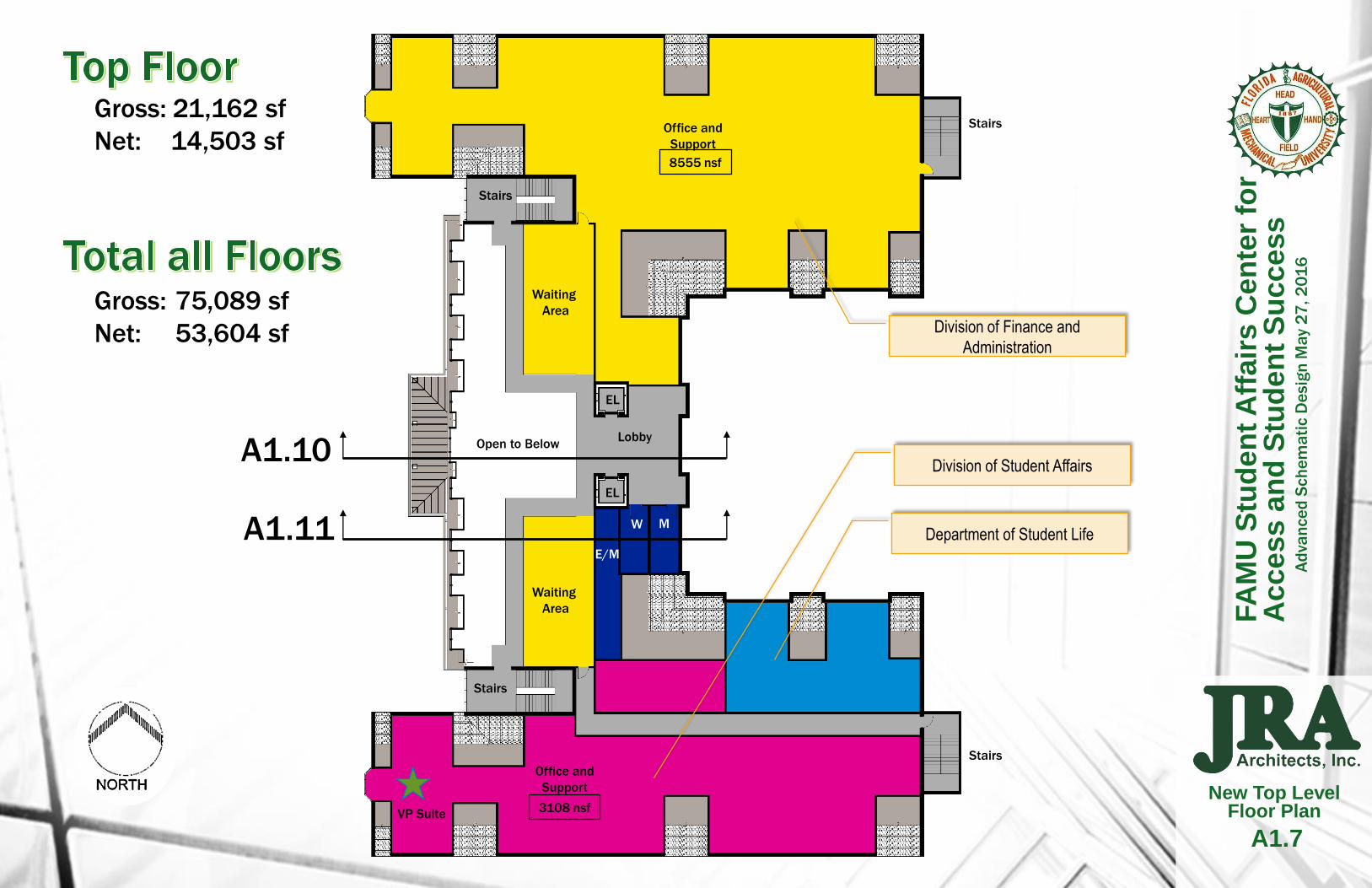
A1.7
New Top Level Floor Plan
Ad
van
ce
d S
ch
em
ati
c D
esig
n M
ay
27
, 2
01
6
A1.10
A1.11E/M
MW
Stairs
Stairs
Stairs
Stairs
Division of Finance and
Administration
8555 nsf
Office and
Support
Department of Student Life
Waiting
Area
Lobby
EL
EL
3108 nsf
Office and
Support
Division of Student Affairs
Waiting
Area
Open to Below
VP Suite
Gross: 21,162 sf
Net: 14,503 sf
Gross: 75,089 sf
Net: 53,604 sf

FA
MU
Stu
de
nt
Aff
air
s C
en
ter
for
Ac
ce
ss
an
d S
tud
en
t S
uc
ce
ss
Ad
van
ce
d S
ch
em
ati
c D
esig
n M
ay
27
, 2
01
6
A1.8
New Front Rendering

FA
MU
Stu
de
nt
Aff
air
s C
en
ter
for
Ac
ce
ss
an
d S
tud
en
t S
uc
ce
ss
A1.9
Courtyard Rendering
Ad
van
ce
d S
ch
em
ati
c D
esig
n M
ay
27
, 2
01
6

FA
MU
Stu
de
nt
Aff
air
s C
en
ter
for
Ac
ce
ss
an
d S
tud
en
t S
uc
ce
ss
A1.10
Building Section
Existing Porch and
West Wall to Remain
New Three Story
Atrium Space
Ground Floor
Reception Area
New Roof and
Dormers to Match
Existing
Ad
van
ce
d S
ch
em
ati
c D
esig
n M
ay
27
, 2
01
6
New Shoring at
Existing Facade Wall
New Exterior
Courtyard
Exposed Trusses at
Atrium
New Stair System

FA
MU
Stu
de
nt
Aff
air
s C
en
ter
for
Ac
ce
ss
an
d S
tud
en
t S
uc
ce
ss
A1.11
Building Section
Ad
van
ce
d S
ch
em
ati
c D
esig
n M
ay
27
, 2
01
6
Existing Porch
BeyondGround Floor
Circulation Corridor
New Roof and
Dormers to Match
Existing
New Shoring at
Existing Facade Wall
New Exterior
Courtyard
Exposed Trusses at
Atrium

FA
MU
Stu
de
nt
Aff
air
s C
en
ter
for
Ac
ce
ss
an
d S
tud
en
t S
uc
ce
ss
A1.12
Wall Sections
Ad
van
ce
d S
ch
em
ati
c D
esig
n M
ay
27
, 2
01
6
New horizontal support at
existing floor system
Existing wood stud and plaster
wall to remain
New exposed painted structure
New Brick façade to remain
Existing foundation to remain
New floor slab
Existing wood truss
and shingle roof
Existing woods to be
refurbished at front
elevation
Existing brick veneer
and wood stud exterior
wall to be salvaged
and reused at front
elevation
Existing floor system to
be removed
Existing concrete
encased steel beam
Existing cast in place
concrete wall and
foundations

FA
MU
Stu
de
nt
Aff
air
s C
en
ter
for
Ac
ce
ss
an
d S
tud
en
t S
uc
ce
ss
Ad
van
ce
d S
ch
em
ati
c D
esig
n M
ay
27
, 2
01
6
A1.13
Submission Checklist

FA
MU
Stu
de
nt
Aff
air
s C
en
ter
for
Ac
ce
ss
an
d S
tud
en
t S
uc
ce
ss
A1.14
Checklist, Schedule and Codes
Proposed Design and Construction Schedule
Submit Conceptual Schematic Design (CSD) April 29, 2016
Approval- CSD May 1, 2016
First Ad runs for CM May 11, 2016
Second Ad runs for CM May 18, 2016
Last Ad runs for CM May 25, 2016
Submit Advanced Schematic Design (ASD) May 27, 2016
CM Proposals Due June 1, 2016
Approval- ASD June 1, 2016
CM Shortlist June 10, 2016
CM Interviews June 23, 2016
CM NTP July 10, 2016
Submit Design Development (DD) July 15, 2016
Approval- DD July 20, 2016
First Draft GMP August 1, 2016
Submit final Demolition Package August 15, 2016
GMP for Demolition Approved September 15, 2016
Demolition Begins September 25, 2016
Submit 75% Documents and Final Civil/Structural October 15, 2016
Final GMP November 15, 2016
Civil Structural Work Begins December 1, 2016
Submit Final Construction Documents January 20, 2017
Substantial Completion March 20, 2018
Final Completion/Move In April 20, 2018
Applicable Codes
Florida Building Code, Building (FBC-B) - 5th edition (2014)
Florida Accessibility Code (FACBC) – 5th Edition (2014)
Florida Building Code, Mechanical (FBC-M) – 5th Edition (2014)
Florida Building Code, Plumbing (FBC-P) – 5th Edition (2014)
Florida Fire Prevention Code (FFPC) – 5th Edition (2014)
National Electrical Code (NEC) - 2011
Ad
van
ce
d S
ch
em
ati
c D
esig
n M
ay
27
, 2
01
6
Pa
st
Eve
nts
Fu
ture
Eve
nts

FA
MU
Stu
de
nt
Aff
air
s C
en
ter
for
Ac
ce
ss
an
d S
tud
en
t S
uc
ce
ss
A1.15
Project Budget
Ad
van
ce
d S
ch
em
ati
c D
esig
n M
ay
27
, 2
01
6
Proposed additive alternates with est. cost

Building BackgroundN.S. McGuinn Hall, designed by Architect Rudolph
Weaver, was constructed in 1937-38 by H. S. Baird,
Inc., of Jacksonville, Florida. The four story women’s
dormitory is in the Georgian Revival Style with a two-
story portico dominating the main entry (West Elevation)
that faces Martin Luther King, JR. Boulevard. The L-
shaped structure’s façade includes a pavilion on the
South end which links the easterly-projecting wing with
the main part of the building and a matching pavilion on
the North end. The north pavilion is actually part of
Diamond Hall, which was joined to McGuinn Hall in
1948. The dormitory has a gross area of 44,740 square
feet.
The building is brick, featuring Flemish bond with
alternating courses of stretchers and headers. There
are brick quoins on the pavilions and the main façade. A
decorative belt course of brick and concrete runs
between the first and second floors of the building. Flat
brick lintels with designs matching the keystones are on
the second floor, and simple flat keystone lintels
emphasize the windows on the third floor. Double-hung
sash, wood framed windows are throughout the
structure. Almost all windows are 6/6 (paired), although
the actual size of the windows varies depending upon
the floor on which they are located. On either side of
the main entry, are paired floor to ceiling, 9/9, double-
hung sash windows.
The central main entrance of McGuinn Hall features a
two-story, 3-bay portico with square columns supporting
its roof. The columns rest on square bases. The door
surround of a main entry features an arched, broken
pediment with pilasters, a transom (6 lights) and side
lights (5 lights each). The gable roof features hip-roofed
dormers on the upper half-story, with a gabled dormer
centered over the main entry. There are nine dormers
on the East and West elevations of the main building,
and eleven dormers on the North and South elevations
of the west wing. The roof line includes a boxed cornice
with dentil work and gable returns in the end pavilions.
The other part of the building, J. T. Diamond Hall, is
significant for its Georgian Revival style architecture. It
is an important component of the Florida A&M College
Historic District, and is associated with a former
Secretary to the State Board of Control, Mr. J.T.
Diamond.
Both McGuinn and Diamond Halls were officially listed
as contributing structures to the “Florida A&M College
Historic District LE 2410” on May 9, 1996.
Florida A&M College Historic
DistrictAs stated, both McGuinn and Diamond Halls are listed
as contributing structures to the “Florida A&M College
Historic District.” After an onsite discussion with the
Staff of the State Historic Preservation Office, Division
of Historical Resources, all parties agreed that both
McGuinn and Diamond would be demolished with only
a portion of the front elevation being saved and
incorporated into the new design. It is the design intent
of the A/E team to salvage and re-use or re-purpose as
many elements of the original structure as possible.
See “Existing Elements to Salvage” (Sheet A1.18) in
this submittal for additional information.
Prior to any work being performed on the building, the
University has authorized JRA Architects to commission
a Level II H.A.B.S.(Historic American Building Survey).
Once completed, the H.A.B.S. will be submitted to the
State Historic Preservation Office, Division of Historical
Resources, to be entered into the State Archives.
FA
MU
Stu
de
nt
Aff
air
s C
en
ter
for
Ac
ce
ss
an
d S
tud
en
t S
uc
ce
ss
A1.16
Project Narrative
Ad
van
ce
d S
ch
em
ati
c D
esig
n M
ay
27
, 2
01
6
Project Narrative

FA
MU
Stu
de
nt
Aff
air
s C
en
ter
for
Ac
ce
ss
an
d S
tud
en
t S
uc
ce
ss
A1.17
Project Narrative
Architectural Design NarrativeAfter an evaluation of the layout and dimensions of the
existing building and a review of the new program, it
became evident that a renovation of the existing
building would be a very difficult, awkward and
financially burdensome venture. As the original building
housed dorm rooms, the building’s narrow width was
not conducive to a layout of office spaces. Additionally,
the existing floor to floor dimension is only 9’-6” which
would not allow enough room for structural
reinforcement and the installation of modern building
systems. Therefore, the demolition of the building
became the most logical course of action.
It should be noted that although the new building design
calls for demolition of the existing structure, the design
team was not insensitive to the historic nature of the
building and its ties to the University’s rich history.
Therefore, it is the intent of the new design to
incorporate a portion of the existing façade, re-use and
re-purpose as many elements of the original structure
as possible and to design the new portion of the
building to reflect, but not mimic, the existing Georgian
Revival style. Two steel and glass stair towers will be
located on each end of the existing façade to provide for
an architectural separation between the new and
existing portions.
In order to maintain the original façade and solve the
problem of the small floor to floor height, the existing
front will be used as the free standing West wall of the
new 3-story open atrium circulation corridor of the new
building. With the removal of the existing floors, new
bracings and shoring will be needed during construction
with portions remaining in the final configuration. The
shoring will be left exposed and uncovered to allow for
distinction between the historic structure and the new
building elements.
The building will house six different Departments, all
associated with Student Services. It is intended to be a
“one-stop shop” with one central and controlled public
access. One exception being a separate public entry to
the Campus Police “Sub-Station” which would be open
24 hours a day. The central access will be through the
existing front door and open into the new 3-story
circulation atrium.
Civil Design NarrativeThe existing building is located in the center of the
campus with the existing front door nearly 13 feet above
MLK Boulevard which traverses the University. The
new structure’s ground floor will be slightly lower than
the existing ground floor which will require cutting of the
exiting site frontage and nearly the entire new footprint,
and site grading away from the building. This will allow
for better accessible access to the new building and the
construction of a new exterior courtyard set in the U-
shaped structure. The courtyard will require stairs and
ramps to return to the original grade, but will allow for
natural light into all courtyard facing windows.
In addition to the demolition of the existing building,
portions of the adjacent existing Gray Building will need
to be removed to allow for access during construction
and pedestrian egress from the rear of the building and
courtyard.
The building is sited near all major utilities with
electricity, water, sewer, data/com, as well as chilled
water lines nearby.
Structural NarrativeThe 3 story building superstructure will likely be
conventional tiered structural steel construction
consisting of steel girder and column frames in each
direction to form the lateral and gravity load resisting
structural systems. Structural X or K - bracing, at
central elevators and pairs of stairs, concealed in wall or
shaft framing, will also be considered in combination
with the column and girder moment frames for optimum
lateral stability.
Elevated floor framing systems of concrete slab on
metal floor deck on open web steel bar joists or light W-
shapes as secondary framing to primary wide flange
steel girders on the structural steel frames are
anticipated. Composite floor systems will be considered
for possible economies if feasible and meet functional
serviceability requirements or thresholds, appropriate
for the space programming.
At the roof, mansards are featured at the building
atrium. Steel trusses are envisioned at a suitable
spacing and depth to match the roof and ceiling profiles
for both the mansard and flat roof sections. A study of
the optimum roof deck and purlin (or steel truss) system
and spacing will be performed based on the roof and
ceiling cavity requirements, and to meet the appropriate
structural loading requirements including wind uplift.
Due to the site slope, the concrete slab on grade at
ground level will be below grade at the front entry
façade. Concrete foundation walls below the façade
will also serve as retaining walls to support the elevated
grade at entry. Shallow reinforced concrete spread
foundations are anticipated for support of the building
superstructure columns and walls subject to
confirmation by geotechnical investigation and
recommendations prior to design.
The historic brick entry façade will be preserved. During
construction, it will be shored and braced for protection.
A bracing system of structural steel tube sections will
provide the permanent back-up in the finished façade
and also support the completed roof structure. Brick
cladding at the building exterior will be laterally
supported by a suitable back-up system spanning
vertically to floor levels.
Mechanical and Electrical
NarrativeThe Mechanical & Electrical Systems for this facility will
be designed using 2014 Florida Building Code, 5th
Edition and State of Florida Fire Marshall Requirements.
The Design will also incorporate FAMU Design
Guidelines and Standards.
The new facility will be connected to the Central Chilled
Water Plant. In coordination with FAMU, Heating will be
provided by a local boiler plant. The Building will be
connected to the Campus Automation System. Central
Air Handlers will provide cooling and heating for the
building. Electrical Power, Lighting, Plumbing, Fire
Protection and A/V, Data, Voice & Security infrastructure
also included in the design.
Ad
van
ce
d S
ch
em
ati
c D
esig
n M
ay
27
, 2
01
6
Project Narrative

FA
MU
Stu
de
nt
Aff
air
s C
en
ter
for
Ac
ce
ss
an
d S
tud
en
t S
uc
ce
ss
A1.18
Existing Elements to Salvage
Cast Stone Sills
Salvaging of
Existing Elements
While the scope of the project calls for
the demolition of the existing
structure, it is the intent of the Design
Team to salvage and reuse many of
the historic elements of the buildings
in the new design. In addition to
incorporating a portion of the front
façade into the design, JRA Architects
is proposing reusing other elements of
the buildings. Several of the items are
shown on this page and include
several pieces of the cast stone, the
copper downspout heads, original
building plaques from both McGuinn
and Diamond and portions of the
Lobby Area. JRA also proposes to
salvage and repurpose existing wood
roof trusses for baseboards and other
wood trim work. The existing wood
windows in the front façade are to be
refurbished.
Windows to be Refurbished at Front Facade
Ad
van
ce
d S
ch
em
ati
c D
esig
n M
ay
27
, 2
01
6Cast Stone Entry Original Building Plaque
Copper Downspout Collectors Cast Stone Entry Lobby Fireplace
Cast Stone Entry Original Building Plaque Lobby Entry Columns

FA
MU
Stu
de
nt
Aff
air
s C
en
ter
for
Ac
ce
ss
an
d S
tud
en
t S
uc
ce
ss
A1.19
Department of State Review
Ad
van
ce
d S
ch
em
ati
c D
esig
n M
ay
27
, 2
01
6