Embed Size (px)
Citation preview

SCHEDULE OF DRAWINGS:
M000 COVER
A100 NOTES AND DETAILS
A101 SITE PLAN AND COOLING TOWER ENCLOSURE
A102 ENCLOSURE DETAILS
S101 STRUCTURAL GENERAL NOTES AND DETAILS
M001 MECHANICAL SYMBOLS LEGEND
MD111 MECHANICAL DEMOLITION PLAN AREA A
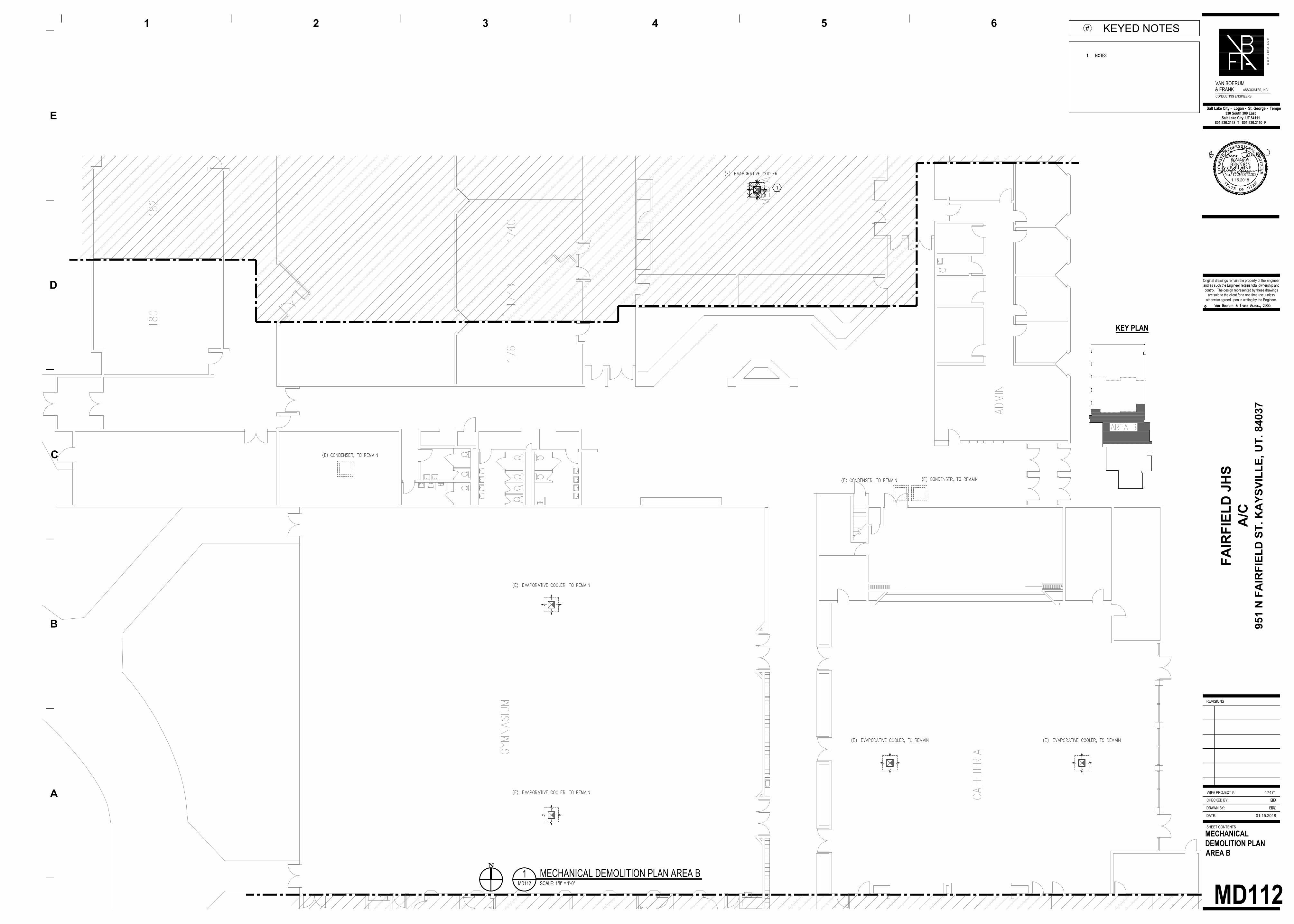
MD112 MECHANICAL DEMOLITION PLAN AREA B
MD113 MECHANICAL DEMOLITION PLAN AREA C
MD114 MECHANICAL DEMOLITION PLAN AREA D
MD401 ENLARGED MECHANICAL DEMOLITION PLAN
M101 OVERALL MECHANICAL PLAN
M111 MECHANICAL PLAN AREA A
M112 MECHANICAL PLAN AREA B
M113 MECHANICAL PLAN AREA C
M114 MECHANICAL PLAN AREA D
M401 ENLARGED MECHANICAL PLANS
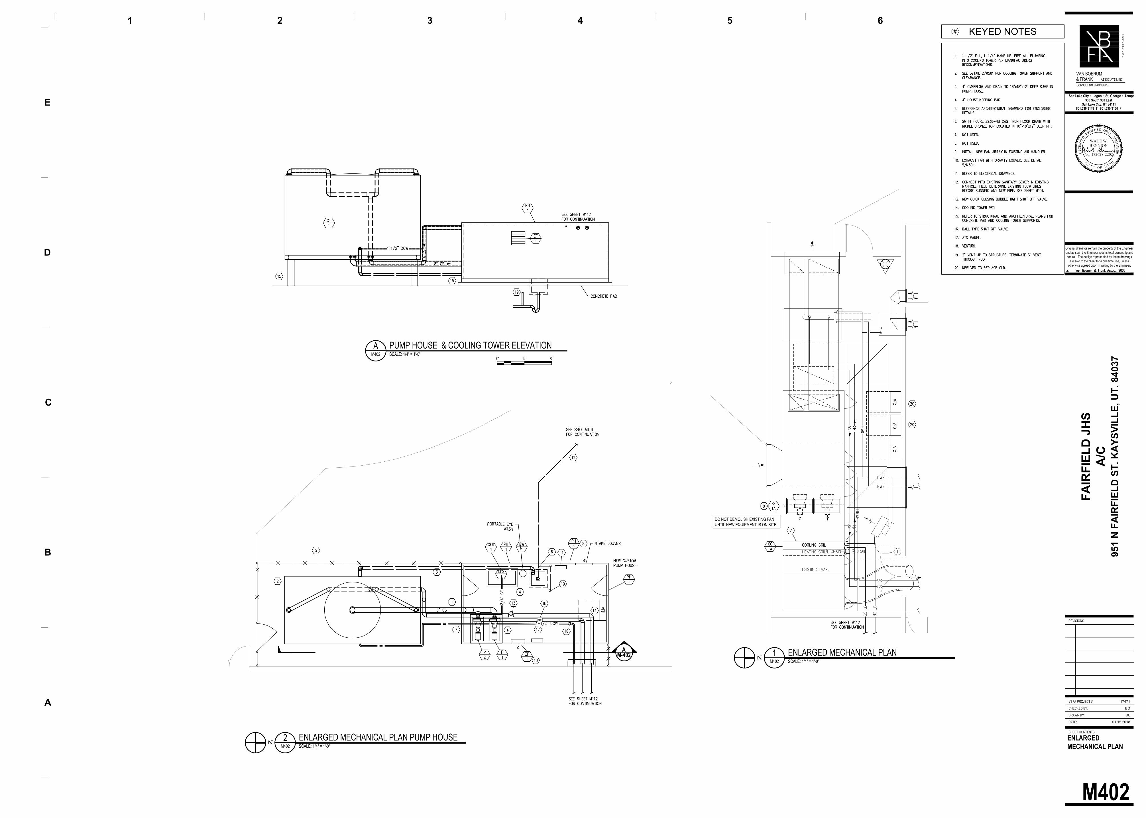
M402 ENLARGED MECHANICAL PLANS
M501 MECHANICAL DETAILS
M601 MECHANICAL SCHEDULES
M701 MECHANICAL SCHEMATIC
EG001 ELECTRICAL GENERAL
EG501 ELECTRICAL DETAILS
EG601 ELECTRICAL SCHEDULES
ED111 ELECTRICAL DEMOLITION PLAN AREA A
ED112 ELECTRICAL DEMOLITION PLAN AREA B
ED113 ELECTRICAL DEMOLITION PLAN AREA C
ED114 ELECTRICAL DEMOLITION PLAN AREA D
ED401 ENLARGED VIEW DEMOLITION PLAN
ED402 ENLARGED VIEW DEMOLITION PLAN
EP101 OVERALL ELECTRICAL PLAN
EP111 ELECTRICAL POWER PLAN AREA A
EP112 ELECTRICAL POWER PLAN AREA B
EP113 ELECTRICAL POWER PLAN AREA C
EP114 ELECTRICAL POWER PLAN AREA D
EP401 ENLARGED ELECTRICAL VIEWS
EP402 ENLARGED ELECTRICAL VIEWS
FAIRFIELD JHS
AIR CONDITIONING ADDITION
DAVIS SCHOOL DISTRICT
DATE: JANUARY, 2018
W W W . V B F A . C O M
Salt Lake City ▪ Logan ▪ St. George ▪ Tempe
VAN BOERUM
& FRANK ASSOCIATES, INC.
CONSULTING ENGINEERS
MECHANICAL ELECTRICAL
330 S. 300 E.
SALT LAKE CITY, UT 84111
T. 801.530.3148
330 S. 300 E.
SALT LAKE CITY, UT 84111
T. 801.530.3148
951 N. FAIRFIELD ST. KAYSVILLE, UT. 84037
VICINITY MAP
FAIRFIELD JHS
ARCHITECTURE + URBAN DESIGN
ARCHITECT
1443 W. 800 N. #102
OREM, UT 84057
T. 801.592.3503
GENERAL NOTES
SECTION 323133 - CHAIN LINK FENCES AND GATES
PART 1 - GENERAL
1.1 RELATED DOCUMENTSA. Drawings and general provisions of the Contract, including General and Supplementary Conditions and Division 01 Specifcation Sections, apply to this Section.
1.2 SUMMARYA. This Section includes the following:
1. Chain-Link Fences: Industrial2. Gates: Horizontal slide and swing.
B. Related Sections include the following:1. Section 033000 "Cast-in-Place Concrete" for concrete2. Section 312000 "Earth Moving" for site excavation, fill, and backfill where chainlink fence and gates are located.
1.3 SUBMITTALSA. Product Data: Include construction details, material descriptions, dimensions of individual components and profiles, and finishes for chain-link fences and gates.
1. Fence and gate posts, rails, and fittings.2. Chain-link fabric, reinforcements, and attachments.3. Gates and hardware.4. Accessories: Privacy slats, if used
B. Shop drawings: show locations of fences, gates, posts, rails, tension wires, details of extended posts, extension arms, gate swing, or other operation, hardware, and accessories. Indicate materials, dimensions, sizes, weights, and finishes of components. Include plans, gate elevations, sections, details of post anchorage, attachment, bracing, and other required installation and operational clearances.
1.4 QUALITY ASSURANCEA. Installer Qualifications: Engage an experienced Installer who has at least three years' experience and has completed at least five chain link fence projects with same material and of similar scope to that indicated for this Project with a successful construction record of in-service performance.B. Single-Source Responsibility: Obtain chain link fences and gates, including accessories, fittings, and fastenings, from a single source.
1.5 PROJECT CONDITIONSA. Field Measurements: Verify layout information for fences and gates shown on the Drawings in relation to the property survey and existing structures.
Verify dimensions by field measurements.
PART 2 - PRODUCTS
2.1 INDUSTRIAL FENCEA. Selvage: Knuckled at one selvage and twisted at the other for 2-inch and 2-1/8-inch mesh sizes and heights above 60 inches.B. Steel Chain-Link Fence Fabric: Fabricated in one-piece widths for fencing 12 feet and less in height to comply with Chain Link Fence Manufactures Institute (CLFMI) "Product Manual" and with requirements indicated:
1. Mesh and Wire Size: 2-inch mesh, 0.148-inch diameter (9 gage)2. Coating: ASTM A 817, Type 2, Class 1, Zinc-coated (Galvanized) applied after weaving.
2.2 FRAMINGA. Selvage: Knuckled at one selvage and twisted at the other for 2-inch and 2-1/8- inch mesh sizes and heights above 60 inches.
Actual NPS Trade OD Size Size
1.660 1-1/4 1.900 1-1/2 2 2.375 2 2-1/2 2.875 2-1/2 3 3.500 3 3-1/2 4.000 3-1/2 4
B. Type I Round Posts: Standard weight (schedule 40) galvanized-steel pipe conforming to ASTM F 1083, according to heavy industrial requirements of ASTM F 669, Group IA, with minimum yield strength of 25,000 psi, not less than 1.8 oz. of zinc per sq. ft. Type A coating inside and outside according to ASTM F 1234, as determined by ASTM A 90, and weights per foot as follows:
Actual NPS Trade OD Size Size
1.660 2.27 1-1/4 1.900 2.72 1-1/2 3.500 7.58 3 4.000 9.11 3-1/2
A. Roll-Formed Steel: Rolled form steel shapes produced from structural-quality steel conforming to ASTM A 570, grade 45, or ASTM A 446, grade D, galvanized, conforming to heavy industrial requirements of ASTM F 669, Group II, with a minimum yield strength of 45,000 psi. Protective coating system according to ASTM F 1234, Type A, hot-dip galvanized with a minimum of 2.0 oz. of zinc per sq. ft. according to ASTM A 123, 4.0 oz. of zinc per sq. ft. according to ASTM A 525.B. Top Rail: Manufacturer's longest lengths (17-21 feet) with swedged-end or expansion-type coupling, approximately 6 inches long for joining. Provide rail ends or other means for attaching top rail securely to each gate corner, pull, and end post.
1. Round Steel: 1.660-inch OD Type I or II steel pipe.
C. Steel posts for fabric heights 6 feet and higher:1. Round Line or Intermediate Posts: 2.375-inch OD Type I or II steel pipe.2. Round End, Corner, and Pull Posts: 2.875-inch OD Type I or II steel pipe.
D. Material: Comply with ASTM F 626. Mill-finished aluminum or galvanized iron or steel to suit manufacturer's standards.E. Post and Line Caps: Provide weathertight closure cap for each post. Provide line post caps with loop to recieve or top rail.F. Post Brace Assembly: Manufacturer's standard adjustable brace. Use material specified below for brace, and truss to line posts with 3/8-inch diameter rod and adjustable tightener. Provide manufacturer's standard galvanized-steel, for each end.
1. Round Steel: 1.660-inch OD Type I or II steel pipe.
G. Tension Wire: 0.177-inch diameter metallic-coated steel marcelled tension wire conforming to ASTM A 824 with finish to match fabric. (If shown on plans.)
1. Coating Type II zinc in the following class as determined by ASTM A 90.a. Class 2, with a minimum coating weight of 1.20 oz. per sq. ft. of uncoated wire surface.
H. Tie Wires: 0.106-inch diameter (12-gage) galvanized steel with a minimum of 0.80 oz. per sq. ft. of zinc coating according to ASTM A 641, or equal, to match fabric wire.
2.3 INDUSTRIAL SWING GATESA. General: Comply with ASTM F 900 for single or double swing gate types.
1. Metal Pipe and Tubing : Galvanized steel. Comply with ASTM F 1043 and ASTM F 1083 for materials and protective coatings.
B. Frames and Bracing: Fabricate members from round, galvanized steel tubing with outside dimension and weight according to ASTM F 900 and the following:
1. Gate Fabric Height: 2 inches (50mm) less than adjacent fence height.2. Leaf Width: As indicated.3. Frame Members:
a. Tubular Steel 1.90 inches (48mm) round.C. Frame Corner Construction:
1. Welded 3/8-inch diameter, adjustable truss rods for panels 5 feet (1.52m) wide or wider.
D. Hardware: Latches permitting operation from both sides of gate, hinges, center gate stops and keepers for each gate leaf more than 5 feet (1.52m) wide.
1. Single: Fork Latch.2. Double: Plunger type drop rod.
2.4 INDUSTRIAL HORIZONTAL-SLIDE GATESA. General: Comply with ASTM F 1184 for single slide gate types.
1. Classification: Type II Cantilever Slide, Class 1 with external roller assemblies.2. Metal Pipe and Tubing: Galvanized steel. Comply with ASTM F 1184 for materials and protective coatings.
B. Frames and Bracing: Fabricate members from round, galvanized steel tubing with outside dimension and weight according to ASTM F 1184 and the following:1. Gate Fabric Height: As indicated on drawings.2. Gate Opening Width: As indicated on drawings.3. Frame members:
a. Tubular Steel: 2.375 inches (60.32mm) round.4. Bracing Members:
a. Tubular Steel: 1.90 inches (48mm) round.C. Frame Corner Construction:
1. Welded frame.D. Roller Guards: As required per ASTM F 1184 for Type II, Class 1 gates.E. Hardware: Latches permitting operation from both sides of gate, roll gate latch.
2.5 CONCRETEA. Conrete: Provide conrete consisting of portland cement per ASTM C 150, aggregates per ASTM C 33, and potable water. Mix materials to obtain concrete with a minimum 28-day compressive strength of 3000 psi. Use at least four sacks of cement per cu. yd., 1-inch maximum size aggregate, 3-inch slump.B. Packaged Concrete Mix: Mix dry-packaged normal-weight concrete conforming to ASTM C 387 with clean water to obtain a 2- to 3-inch slump.
PART 3 - EXECUTION
3.1 EXAMINATIONA. Examine areas and conditions, with Installer present, for compliance with requirements for site clearing, earthwork, pavement work and other conditions affecting performance.
1. Do not begin installation before final grading is completed, unless otherwise permitted by Architect.2. Proceed with installation only after unsatisfactory conditions have been corrected.
3.2 INSTALLATION, GENERALA. General: Install fence to comply with ASTM F 567. Do not begin installation and erection before final grading is completed, unless otherwise permitted.
1. Apply fabric to outside of framework. Install fencing on boundary lines linside property line established by survey.
3.3 CHAIN LINK FENCE INSTALLATIONA. Excavation: Drill or hand-excavate (using post-hole digger) holes for posts and spacings indicated, in firm, undisturbed or compacted soil.
1. If not indicated on Drawings, excavate holes for each post to minimum diameter recommened by fence manufacturer, but not less than four times the largest cross section of post.2. Unless otherwise indicated, excavate hole depths approximately 3 inches lower than post bottom, with bottom of posts set not less than 36 inches below finish grade surface.
B. Setting Posts: Center and align posts in holes 3 inches above bottom of excavation. Space a maximum of 10 feet o.c., unless otherwise indicated.
1. Protect portion of posts above ground from concrete splatter. Place concrete around posts and vibrate or tamp for consolidation. Check each post for vertical and top alignment, and hold in position during placement and finishing operations.
a. Unless otherwise indicated, extend concrete footings 2 inches above grade and trowel to a crown to shed water.
C. Top Rails: Run rail continuously through line post caps, bending to radius for curved runs and at other posts terminating into rail end attached to posts or post caps fabricated to receive rail. Provide expansion couplings as recommended by fencing manufacturer.D. Brace Assemblies: Install braces at end and gate posts and at both sides of corner and pull posts. Locate horizontal braces at midheight of fabric on fences with top rail and at two thirds fabric height on fences without top rail. Install so posts are plumb when diagonal rod is under proper tension. (If shown on plans.)E. Bottom Tension Wire: Install tension wire within 6 inches of bottom of fabric before stretching fabric and tie to each post with not less than same gage ond type of wire. Pull wire taut, without sags. Fasten fabric to tension wire with .120-inch diameter (11-gage) hog rings of same material and finish as fabric wire, spaced a maximum of 24 inches o.c.F. Fabric: Leave approximately 2 inches between finish grade and bottom selvage unless otherwise indicated. Pull fabric taut and tie to posts,rails, and tension wires. Install fabric on security side of fence, and anchor to framework so that fabric remains under tension after pulling force is released.G. Tie Wires: Use wire of proper length to secure fabric firmly to posts and rails. Bend ends of wire to minimize hazard to persons or clothing.
2. Maximum Spacing: Tie fabric to line posts 12 inches o.c. and to rails and braces 24 inches o.c.H. Fasteners: Install nuts for tension bands and carriage bolts on the side of the fence opposite the fabric side. Peen ends of bolts or score threads to prevent removal of nuts for added security.I. Privacy Slats: Install slats in direction indicated, securely locked in place. (If shown on plans.)
1. Vertically.
3.4 GATE INSTALLATIONA. Install gates according to manufacturer's written instructions, level, plumb, and secure for full opening without interference. Attach fabric as for fencing. Attach hardware using tamperresistant or concealed means. Install ground-set items in concrete for anchorage. Adjust hardware for smooth operation and lubricate where necessary.
3.5 ADJUSTINGA. Gate: Adjust gate to operate smoothly, easily, and quietly, free of binding, warp, excessive deflection, distortion, nonalignment, misplacement, disruption, or malfunction, throughout entire operational range. Confirm that latches and locks engage accurately and securely without forcing or binding.
EXTERIOR
1. Contractor to verify all dimensions on drawings for layout prior to construction with actual field conditions. Contractor to report any discrepancies to Architect and or Mechanical Engineer.
2. Contractor to coordinate and review with district for all staging, construction zones, barricade, parking and temporary fencing. Coordinate with district to maintain existing access for school deliveries, public andstudent safety access and exiting during all construction phases.
3. General contractor to retain soils engineers approved by School District for verification of soils bearing capacity for a minimum 2,000 lbs per foot.Selected soils engineer shall approve all undisturbed soils below all interior /exterior concrete slabs and footings typical, unless otherwise noted.Contractor to provide 6” free draining gravel under all slabs. If soils mediation / imports are required, soils engineer shall approve new imported engineered fill.Fill installed in 8” lifts, compacted to 95% maximum relative density for all soils bearing conditions. Imported fill to be type 1 Pit run gravel underneath all footings typical, unless otherwise noted, or as per soilsengineer's approval.
4. Contractor to verify existing gas piping routing in lawn area where new chiller enclosure is to be located, prior to excavation. Refer to plumbing drawings for notes.
5. Contractor to verify and work with district personnel for location of all irrigation piping, valve boxes, and heads prior to commencement of work impacted by new construction.Contractor to re-route, adjust and cap abandon lines not used. Contractor to provide new layout for fully functional irrigation system maintaining existing zone for this area impactedby new construction. Contractor to review type and manufacture of all irrigation heads replacement with district standards.
6. Contractor to provide rough grading free of large rocks and or construction debris for new landscaping. Provide the placement of 2 ” imported and amended topsoil for the placement of new lawn sod. New sodarea within existing curbs area left after construction of new chiller enclosure. Provide one (1) mowing after installing new or replacing existing sod.
7. Contractor to provide earth bank shoring, wall bracing or form bracing and other shoring work for all permanent concrete members as required. Shoring for the construction of footings, foundation walls, retainingwalls, sidewalks and other structures for the protection and safetyshall be the responsibility of the contractor. Back filling shall not take place until all connection are complete and structurally sound.
8. Contractor shall be responsible for the location of all existing utilities in the area of construction for location. Report all conflicts to owner and or engineer for district clarification and direction prior toconstruction.
INTERIOR
1. Remove and store all demolished fixtures and equipment for Owner review and approval prior to disposal.
2. Remove all ceilings, grids, or fixtures necessary to perform the required work. Replace all damaged materials after installation of equipment with new assemblies matching adjacent existing assemblies.
3. The contractor shall protect all existing finishes to remain from construction damage.
4. All penetrations through rated assemblies shall be fire stopped with a District approved material which maintains the original assembly rating.
A.
B.
C.
D.
1.E.
A.
B.
C.
D.
E.1.
2.
3.
4.
5.6.
7.
8.
9.
A.
B.
A.
1.2.
3.
A.
B.
A.
POLYVINYL-CHLORIDE (PVC) ROOFING –CURB/PIPE ADDITIONS
PART 1 - GENERAL
1.1 PERFORMANCE REQUIREMENTSGeneral Performance: Installed membrane roofing and base flashings shall withstandspecified uplift pressures, thermally induced movement, and exposure to weatherwithout failure due to defective manufacture, fabrication, installation, or other defectsin construction. Membrane roofing and base flashings shall remain watertight.Material Compatibility: Provide roofing materials that are compatible with one anotherunder conditions of service and application required, and demonstrated by membraneroofing manufacturer based on testing and field experience.Roofing System Design: Provide membrane roofing system that is identical to systemsthat have been successfully tested by a qualified testing and inspecting agency toresist uplift pressure calculated according to ASCE/SEI 7.FM Approvals Listing: Provide membrane roofing, base flashings, and componentmaterials that comply with requirements in FM Approvals 4450 and FM Approvals 4470as part of a membrane roofing system. Identify materials with FM Approvals markings.
Fire/Windstorm Classification: Class 1A-90.Energy Performance: Provide roofing system that is listed on the DOE ’s ENERGY STAR“Roof Products Qualified Product List ” for low-slope roof products.
1.2 QUALITY ASSURANCEManufacturer Qualifications: A qualified manufacturer that is UL listed for membraneroofing system identical to that used for this Project.Installer Qualifications: Installer shall have five (5) years minimum experienceinstalling the proposed membrane with an elite status with manufacture, unless priorapproval from Architect, Owner, and General Manager has been made.Source Limitations: Obtain components including fasteners for membrane roofingsystem approved by Owner and or membrane roofing manufacturer.Exterior Fire-Test Exposure: ASTM E 108, Class A; for application and roof slopesindicated, as determined by testing identical membrane roofing materials by a qualifiedtesting agency. Materials shall be identified with appropriate markings of applicabletesting agency.Pre-installation Roofing Conference: Conduct conference at Project site.
Meet with Owner, Architect, Owner ’s insurer if applicable, testing and inspectingagency representative, roofing installer, roofing system manufacturer ’srepresentative, deck installer, and installers whose work interfaces with or affectsroofing, including installers of roof accessories and roof-mounted equipment. Review methods and procedures related to roofing installation, includingmanufacturer’s written instructions.Review and finalize construction schedule and verify availability of materials,Installer’s personnel, equipment, and facilities needed to make progress and avoiddelays.Examine deck substrate conditions and finishes for compliance with requirements,including flatness and fastening.Review structural loading limitations of roof deck during and after roofing.Review base flashings, special roofing details, roof drainage, roof penetrations,equipment curbs, and condition of other construction that will affect roofingsystem.Review governing regulations and requirements for insurance and certificates ifapplicable.Review temporary protection requirements for roofing system during and afterinstallation.Review roof observation and repair procedures after roofing installation.
1.3 DELIVERY, STORAGE, AND HANDLINGDeliver roofing materials to Project site in original containers with seals unbroken andlabeled with manufacturer ’s name, product brand name and type, date of manufacture,approval or listing agency markings, and directions for storing and mixing with othercomponents.Store liquid materials n their original undamaged containers in a clean, dry, protectedlocation and within the temperature range required by roofing system manufacturer.Protect stored liquid material from direct sunlight.
1. Discard and legally dispose of liquid material that cannot be applied within its statedshelf life.C. Handle and store roofing materials and place equipment in a manner to avoid permanentdeflection of deck.
1.4 PROJECT CONDITIONSA. Weather Limitations: Proceed with installation only when existing and forecastedweather conditions permit roofing system to be installed according to manufacturer ’swritten instructions and warranty requirements.
1.5 WARRANTYA. Special Warranty: Manufacturer ’s standard or customized form, without monetarylimitation, inwhich manufacturer agrees to repair or replace components of membrane roofing systemthat fail in materials or workmanship within specified warranty period.
No exclusions for ponding water.Special warranty includes membrane roofing, base flashings, fasteners, substrateboard, roofing accessories, and other components of membrane roofing system.Warranty Period: Keep existing warranty in place and valid.
B. Special Project Warranty: Submit roofing Installer ’s warranty, on warranty formapproved by Owner, signed by Installer, covering the Work of this Section, including allcomponents of membrane roofing system such as membrane roofing, base flashing,fasteners, substrate boards, and walkway products, for the following warranty period:1. Warranty Period: Two years from date of Substantial Completion.PART 2 - PRODUCTS
2.1 PVC MEMBRANE ROOFINGA. PVC Sheet: ASTM D 4434, Type lll, fabric reinforced. Match existing roof membrane.
1. 60 mils nominal.
1. The components of this roof system are to be products of one manufacturer. Productsnot supplied by primary roof membrane manufacturer, shall be identified as beingcompatible, acceptable and under warranty by the membrane manufacturer.
Acceptable Manufacturer and roof membrane for use on this project shallcomply to the following requirements:
Curb Flasings- G410, .060 minimum thickness, glass fiber reinforcedPolyvinyl Chloride membrane. Color:Energy Smart White.Pipe Flashings- Standard pre-formed pipe boots or field fabricatedwraps as warranted by manufacturer.
2. Membrane adhesive shall be supplied by the membrane manufacturer.Acceptable adhesive shall include:
A. Solvent based 2170 adhesive meeting current VOC requirements.B. As required by Membrane manufacturer.
3. Membrane Cleaner, Bonding Cement, Multi-purpose Sealant, Flashing,termination Bars, Mechanical Fastener ’s, Water Cut off Mastic and pourable sealeras manufactured and supplied by the membrane manufacturer.
4. Membrane Flashing:
A. Inside/outside corners or vent stacks shall be fieldfabricated fiberglass reinforced membrane in the same color asfield membrane. Supplied by the membrane manufacturer.
5. Fasteners : #12 steel painted screw for insulation or hard board attachment.
6. Membrane Cleaner:
A solvent cleaner for removal of adhesives from lap areas and for removalof contaminants from the roofing membrane as supplied by themembrane manufacturer.
7. Sealants:
Caulking / sealants which are provided will be accepted for use with thisinstallation based on chemical compatibility with the specifiedmembranes:
Multi purpose sealant tape or sealant in caulking tubes. Assupplied by membrane manufacturer.
A.
A.
A.
A.
1.2.
A.
1.
2.
B.
A.
B.C.
D.
A.
B.
A.
A.
B.
C.
D.
E.
A.
A.
B.
A.
B.
C.
8. Coated Metal25 gauge galvanized PVC coated steel sheets. Color to match roofmembrane color or as directed by owner. Membrane cover strips tomatch colored metal shall be provided by manufacturer as part of theflashing package. Steel flashing shall be formed to meet projecttermination and flashing requirements. Supplied and warranted bymembrane manufacturer.
2.2 AUXILIARY MEMBRANE ROOFING MATERIALSGeneral: Auxiliary membrane roofing materials recommended by roofing systemmanufacturer for intended use, and compatible with membrane roofing.
1. Liquid-type auxiliary materials shall comply with VOC limits of authorities havingjurisdiction.B. Sheet Flashing: Manufacturer ’s standard sheet flashing of same material, type,thickness, and color, as PVC sheet membrane.C. Bonding Adhesive: Manufacturer ’s standard.D. Metal Termination Bars: Manufacturer ’s standard, predrilled stainless-steel oraluminum bars, approximately 1 by 1/8 inch thick; with anchors.E. Fasteners: Factory-coated steel fasteners and metal or plastic plates complying withcorrosion-resistance provisions in FM Approvals 4470, designed for fastening membrane tosubstrate, and acceptable to membrane roofing system manufacturer.F. Coated Flashings: Manufacturer ’s standard coated metal flashings in thickness asrecommended by manufacturer for indicated use and complying with performancerequirements, but with metal thickness not less than 0.028 inches.G. Miscellaneous Accessories: Provide cone and vent sheet flashings, inside and outsidecorner sheet flashings, T-joint covers, termination reglets, and other accessories.
2.3 INSULATION MATERIALSSubstrate Board: Rigid polyisocyanurate with black mat facers 4 ’x8’ installed in twolayers to meet desired r-value.
2.4 WALKWAYSFlexible Walkways: Factory-formed, heavy-duty, slip-resisting, surface-texturedwalkway pads, approximately 3/16 inch thick and acceptable to membrane roofingsystem manufacturer.
Size: 3'-0" wide by lengths indicated or as graphically shown on the roof plans.Provide around roof access hatch, at high roof drip edge and around mechanicalequipment as indicated on the drawings.
3.1 EXAMINATIONExamine substrates, areas, and conditions, with Installer present, for compliance withthe following requirements and other conditions affecting performance of roofingsystem:
Verify that roof openings and penetrations are in place and curbs are set andbraced.Verify that wood blocking, curbs, and nailers are securely anchored to roof deck atpenetrations.
Proceed with installation only after unsatisfactory conditions have been corrected.
3.2 PREPARATIONClean substrate of dust, debris, moisture, and other substances detrimental to roofinginstallation according to roofing system manufacturer ’s written instructions. Removesharp projections.Prevent materials from spilling or migrating onto surfaces of other construction.Complete terminations and base flashings and provide temporary seals to prevent waterfrom entering completed sections of roofing system at the end of the workday or whenrain is in the forecast. Remove and discard temporary seals before beginning wok onadjoining roofing.Do not begin installation in inclement weather and lonely install as much insulation in aday as can be covered with the roof membrane.
3.3 INSULATION (SUBSTRATE) BOARDSInstall substrate board with long joints in continuous straight lines, perpendicular toroof slopes with end joints staggered between rows. Tightly butt substrate boardstogether.Install second layer with end and side joints offset one-foot minimum from joints in firstlayer.
3.4 MECHANICALLY FASTENED MEMBRANE ROOFING INSTALLATIONMechanically fasten membrane roofing over area to receive roofing and installaccording to roofing system manufacturer ’s written instructions.
1. Install sheet according to ASTM D 5082.B. Start installation of membrane roofing in presence of roofing system manufacturer ’stechnical personnel.C. Accurately align membrane roofing and maintain uniform side and end laps of minimumdimensions required by manufacturer. Stagger end laps.D. Mechanically fasten or adhere membrane roofing securely at terminations,penetrations, and perimeter of roofing.E. Apply membrane roofing with side laps shingled with slope of roof deck where possible.F. Seams: Clean seam areas, overlap membrane roofing, and hot-air weld side and endlaps of membrane roofing and sheet flashings according to manufacturer ’s writteninstructions to ensure a watertight seam installation.
1. Test lap edges to prove and verify seam weld continuity.2. Verify field strength of seams a minimum of twice daily and repair seam sample
areas.3. Repair tears, voids, and lapped seams in roofing that does not comply with
requirements.
3.5 BASE FLASHING INSTALLATIONInstall sheet flashings and preformed flashing accessories and adhere to substratesaccording to membrane roofing system manufacturer ’s written instructions.Apply bonding adhesive to substrate and underside of sheet flashing at required rateand allow to partially dry. Do not apply to seam area of flashing.Flash penetrations and field-formed inside and outside corners with cured or uncuredsheet flashing.Clean seam areas, overlap, and firmly roll sheet flashings into the adhesive. Hot-airweld side and end laps to ensure a watertight seam installation.Terminate and seal top of sheet flashings.
3.7 WALKWAY INSTALLATIONFlexible Walkways: Install walkway products in locations indicated. Heat weld tosubstrate or adhere walkway products to substrate with compatible adhesive accordingto roofing system manufacturer’s written instructions.
1. Install walkways around all sides of mechanical rooftop equipment, at roof accesshatches and under eaves of high roof along drip line.
3.8 FIELD QUALITY CONTROLRepair or remove and replace components of membrane roofing system whereinspections indicate that they do not comply with specified requirements.Additional inspections, at contractor’s expense, will be performed to determinecompliance of replaced or additional work with specified requirements.
3.9 PROTECTING AND CLEANINGProtect membrane roofing system from damage and wear during remainder ofconstruction period. When remaining construction will not affect or endanger roofing,inspect roofing for deterioration and damage, describing its nature and extent in awritten report, with copies to Architect and Owner.Correct deficiencies in or remove membrane roofing system that does not comply withrequirements; repair substrates; and repair or reinstall membrane roofing system to acondition free of damage and deterioration at time of Substantial Completion andaccording to warranty requirements.Clean overspray and spillage from adjacent construction using cleaning agents andprocedures recommended by manufacturer of affected construction.
BUILT-UP ROOFING (BUR) NEW PENETRATION OR MECH. CURB
A. Thoroughly clean roof surface of dirt, debris, loose granules and contaminates at andaround location of new penetrations or curbs. Spread the gravel back from the edge of thenew penetration or curb 12-inches minimum. Prime area and allow to dry.B. Provide new flashing vertically 8-inches minimum at pipe or curb. Provide 4-incheshorizontal flange at flashing, prime both sides with asphalt primer and let dry. Set horizontalflange over top ply of field roofing in approximately 1/8-inch-thick layer of manufacturer ’sapproved utility cement.C. Strip-in horizontal flange with fiberglass mesh with a coat of plastic-roofing cement.Apply additional coats of plastic-roofing cement extending cement to cover joint betweenthe felt and flashing. Slope flashing to shed water.D. Coat plastic-roofing cement with aluminum roof coating.E. Provide 22-gauge galvanized rain collar at top of pipe penetration. Secure collar withstainless steel draw band set in urethane sealant. Seal top of rain collar.
DATE:
DRAWN BY:
CHECKED BY:
SHEET CONTENTS
REVISIONS
Original drawings remain the property of the Engineer
and as such the Engineer retains total ownership and
control. The design represented by these drawings
are sold to the client for a one time use, unless
otherwise agreed upon in writing by the Engineer.
BL
BD
01.15.2018
A
B
D
E
1 2 3 4 5
W W
W
. V
B
F
A
. C
O
M
VBFA PROJECT #: 17471
330 South 300 East
Salt Lake City, UT 84111
801.530.3148 T 801.530.3150 F
Salt Lake City ▪ Logan ▪ St. George ▪ Tempe
VAN BOERUM
& FRANKASSOCIATES, INC.
CONSULTING ENGINEERS
C
6
FA
IR
FIE
LD
J
HS
A/C
951 N
F
AIR
FIE
LD
S
T. K
AY
SV
IL
LE
, U
T. 84037
A100
ARCHITECTURAL
SPECIFICATIONS
AND GENERAL
NOTES
A101A1
6"1'-
0"
8"
6"
1" C
LR.
19'-4"4'-7"
6'-1"
4'-10" 53'-10" 6'-0"
7'-0"7'-3"
9'-8"
A4A101
D4A101D4
A101
6"1'-
0"
8"
1" C
LR.
8'4'2'0'
N 1" = 50'-0"D1 OVERALL SITE PLAN 1" = 1'-0"D4 SLAB EDGE AT EQUIPMENT
8'4'2'0'
N 1/8" = 1'-0"A1 ENLARGED ENCLOSURE PLAN 1 1/2" = 1'-0"A4 SIDEWALK AT SLAB EDGE
DATE:
DRAWN BY:
CHECKED BY:
SHEET CONTENTS
REVISIONS
Original drawings remain the property of the Engineer
and as such the Engineer retains total ownership and
control. The design represented by these drawings
are sold to the client for a one time use, unless
otherwise agreed upon in writing by the Engineer.
BL
BD
01.15.2018
A
B
D
E
1 2 3 4 5
W W
W
. V
B
F
A
. C
O
M
VBFA PROJECT #: 17472
330 South 300 East
Salt Lake City, UT 84111
801.530.3148 T 801.530.3150 F
Salt Lake City ▪ Logan ▪ St. George ▪ Tempe
VAN BOERUM
& FRANKASSOCIATES, INC.
CONSULTING ENGINEERS
C
6
SY
RA
CU
SE
JH
S
A/C
14
50
S
OU
TH
2
00
0 W
ES
T, S
YR
AC
US
E U
T. 8
40
75
A101
ARCHITECTURAL
COOLING TOWER
ENCLOSURE AND
DETAILS

B1. Governing Building Code: 2015 International Building Code (IBC) B2. Gravity Loading A. Roof...............20 psf dead load Snow Loads Plus Snowdrift Pg= 43psf Pf= 30 psf Ce= 1.0 Is= 1.1 Ct= 1.0
SW1. A minimum of 12" of topsoil shall be removed from the entire building site including all vegetation and debris. SW2. All bearing earth to be undisturbed earth or compacted fill. The area on which the fill is placed must be frost free. The fill shall then be placed in layers not to exceed 8 inches in depth and compacted.
SW3. All fill and back fill shall be compacted to a minimum of 95% of maximum relative density TYP. and 90% for landscaped area not supporting structural loads; structural fill based on AASHTO T180.
SW4. Any fill to be placed under the building and footings shall be a well graded granular material within the limits of the following gradation, unless otherwise specified by Soils Engineer: Sieve Size Percent Passing 4" 100 1" 60-90 #4 30-60 #40 10-30 #200 5-12
SW5. All water shall be removed from foundation excavation prior to placing of concrete. Do not pour concrete under water. SW6. Any unusual soil conditions (water, clay, soft layers, etc.) encountered during excavation for footings shall be immediately brought to the attention of the architect and soils engineer. SW7. All foundation excavations shall be protected from all detrimental changes in environmental conditions such as rain and freezing.
SW8. Contractor shall coordinate the architectural, structural, and civil drawings for top of footing elevations and footing steps and excavations. SW9. Contractor shall verify all existing and future grades. Footings shall be poured to maintain the minimum frost protection or confinement indicated on details. Footing steps shall be provided as per typical details where required by site conditions.
C1. All work and materials shall comply with all areas of ACI318 and ACI 347 Publications and applicable ASTM Publications. C2. Compressive strength of concrete at 28 days shall be as follows: (only 1-grade of concrete shall be poured on the job at one time). Use type II cement in contact with ground.
Minimum Compressive Slump % Water/ Maximum Special Strength(psi) (+/- 1") Air Cement Aggregate Inspection (At 28 Days) TYP.U.N.O. Entrainment Ratio Size Required
Ext.Slab on Grade 4500 3 +/- .5" 5.5% to 7.5% .45 1" NOExposed Exterior 4500 3" 5.5% to 7.5% .45 1" Concrete
C3. Hardrock aggregates shall conform to ASTM C-33. Their Maximum size shall be 3/4" except 1" shall be used for footings and slabs on grade.
C4. The contractor shall submit mix design and 3, 7, and 28 days strength tests for review by the structural engineer before any concrete is poured at the job site.
C5. All concrete that is placed by pumping shall be medium range- plasticized with water reducing admixture which shall comply with specifications for chemical admixtures for concrete, ASTM designation C-494 non-chloride and shall be used in strict accordance with manufacturer's recommendations. Product specification publication shall be submitted to structural engineer for review.
C6. Unless otherwise noted all reinforcement bars shall be securely anchored to the forms and spaced from them as follows: Minimum Coverage
A. Cast against & exposed to earth.......3 inches B. Concrete exposed to earth or weather: #6 though #18 bars....................2 inches #5 bar and smaller....................1 1/2 inches C. Not exposed to weather or in contact with ground: slabs, walls, joists:.....3/4 inches C7. Reinforcing Steel A. All reinforcing steel shall be bent, detailed and chaired
as per the "ACI Manual of Standard Practice for Detailing Reinforcing Concrete Structures."
B. All reinforcing steel to be welded shall comply with ASTM A706.
C. All reinforcing steel shall be of new stock deformed bars conforming to ASTM A-615 grade 60 unless otherwise noted. Placement of bars in accordance with ACI 315 and ACI 318. Use bar supports per ACI 315 chapter 7 for all rebar and welded wire fabric. As per ACI 318, Section 7.5.1: "All reinforcement shall be accurately placed and adequately supported before concrete is placed and shall be secured against displacement within tolerances permitted in 7.5.2." Wet stabbing reinforcing is not allowed.
D. Unless otherwise indicated, all anchors welded to steel plates or angles that are embedded in masonry or concrete shall be deformed bar anchors conforming to A36 Steel or ASTM A706.
E. Minimum standard rebar lap lengths: #3=19" #4=25" #5=31" #6=37" #7=54" #8=62" #9=70" #10=78" #11=85". Epoxy coated bar laps, multiply above values by 1.2. For epoxy coated rebars or wires with cover less than 3db or clear spacing less than 6db, the laps shall multiply the above values by 1.5. Lightweight concrete bar laps, multiply above values by 1.3. (ie. #6=37"x1.3=48"). If more than 12" concrete is below rebar (beam top reinforcing), multiply above values by 1.3. (ie. #5=31"x1.3=47"). See shear wall schedule for seismic lap lengths. All vertical reinforcing bars (unless noted otherwise) shall be doweled to footing with 90 degree standard hook.
K. When called for on the drawings or when directed by engineer bars that are to be epoxy doweled are to be put in holes larger than the bar diameter as per manufacturer's recommendation. The holes shall be ten bar diameters deep for 4000 psi concrete or above and 15 bar diameters for concrete below 4000 psi. Fill holes with "Hilti" HIT RE 500 SD, HIT-HY 150-SD, or Simpson SET-XP. Epoxy Anchors into grouted masonry wall should be "Hilti- Hy 150 MAX" or Simpson "SET" with 10 bar diameters min. embedment. All epoxy dowels and epoxy anchors are to be either threaded or deformed bars as per drawings. Apply epoxy as per manufacturer's recommendations. Mixing shall be done using a power mixer. For cold weather application gel shall be mixed at 70 degrees and kept at 40 degrees for 72 hours after application. Impact type drilling tools shall not be used for drilling holes or tightening anchors and shear bolt nuts into or through brick. SPECIAL INSPECTION IS REQUIRED.
C8. Concrete tests shall be made by testing laboratory approved by the architect, with copies of all reports being mailed to the architect and the contractor. In general, one test shall be made for each 50 cubic yards of concrete, or each days' pour if less than 50 yards, or as directed by Architect. Each test shall consist of 5 cylinders of which one shall be tested at 7 days, 2 tested at 28 days, and two retained in reserve for later tests, if required. Specimens shall be made and tested in accordance with ASTM C-172, C-31 and C-39 standards. Slump and Air entrainment test shall also be made with each set of cylinders taken. Contractor shall provide the cylinders. The testing laboratory shall transport all cylinders. The owner shall pay for all tests. Samples should be taken at the truck discharge.
C9. Before concrete is poured, check with all trades to insure proper placement of all openings, sleeves, curbs, conduits, bolts, inserts, etc. relating to work.
C10. Drypack concrete shall be one part Portland cement and one part sand with sufficient water to allow a small amount of paste to come to the surface. Use for grouting joists and beam pockets unless otherwise noted.
C11. Under steel column base plates, concrete grout shall be non-shrink with sufficient water to allow pouring. Ultimate compressive strength (F'C) at 28 days shall = 4,000 psi. Grout shall be non-metallic, meeting CRD-C621 and in accordance with the manufacturer's published specification for mixing and placing.
C12. All exposed to view concrete shall be stoned smooth while green, or as directed by Architect. No grout plaster shall be permitted. Exposed to view concrete shall have 3/4" deep "V" groove placed vertically at 8'-0" o.c. or as directed by Architect.
C13. Protect freshly placed concrete from premature drying and excessive cold or hot temperature as per ACI 318 and maintain without drying at a relatively constant temperature for a period of time necessary for hydration of cement and proper hardening.
C14. Cold weather curing and protection requirements for concrete shall conform to the requirements of ACI 306 when depositing concrete at freezing temperature or below, the concrete mix shall have a temperature of at least 50 degrees but not more than 80 degrees. The concrete shall be maintained at a temperature of not less than 50 degrees and in a moist condition for not less than 7 days after placing or as directed by the structural engineer. The use of chemicals or additives to prevent freezing will not be permitted. Contractor shall prevent frost from penetrating under footings or interior slabs on grade or postpone concrete pour. Refer also to specifications and to any directive by structural engineer for additional cold weather requirements.
C15. Architect/Engineer shall be notified 48 hours prior to pouring any concrete in order to observe reinforcing placement.
C16. All concrete shall be properly vibrated in place using internal vibrating rods.
C17. Unless otherwise noted all concrete slabs apply a liquid type membrane forming curing compound complying with ASTM C 309, type 1, class A Moisture loss shall be not more than 0.055 gr./sq. cm. applied at 200 sq.ft./gal. When temperature is 75 degrees or more during curing do not use membrane but moist cure slab for 7 days continuous minimum and/or see ACI Committee 305R4.4.1 Report "Hot Weather Concreting". Submit method of curing for approval. When slab is not covered by carpet, wet-curing is required for 7 days minimum or see ACI- 224R for additional recommendations.
C18. Expansion anchors cast into concrete should be "Simpson Strong Bolt" or Simpson Titen HD, or "Hilti Kwik Bolt TZ" or "Hilti Kwik HUS-EZ", or equal; and expansion anchors cast into masonry walls should be "Hilti Kwik Bolt 3" or Simpson "WEDGE-ALL" or equal. Contact structural engineer for approval prior to installation.
S1. All structural steel work shall comply with the latest edition of the AISC "Standard Specifications for the Design, Fabrication and Erection of Structural Steel for Buildings", and "Code of Standard Practice". ASTM A-992 FY=50 ksi minimum specified for structural shapes; A36 steel for miscellaneous steel; ASTM A-500 grade B for structural tubes; ASTM A-53 for structural pipes; typical U.N.O. Cambering shall meet the standard mill practice shown on AISC "Manual of Steel Construction".
S2. Shop paint and remove all rust, oils, mill scale. Apply one coat zinc chromate 2 dry mills thick. Provide touch up field coat at all abraded and welded areas, two dry mills thick. All steel exposed to moisture conditions shall be galvanized. (Follow SSPC - Paint 20; ASTM A 780)
S3. Unless noted otherwise, all structural steel to steel bolted connections shall use 3/4" diameter high strength bolts conforming to ASTM A-325 (N) and shall have carbonized washers under the turning unit. All other bolts shall conform to ASTM A-307, and shall be galvanized.
S4. Unless noted otherwise on plans, all steel stairs shall have C12 x 20.7 stringers with concrete filled 12 gage welded pans and risers.
S5. The supports of basketball standards shall be provided by the supplier and the design and connection shall be reviewed by the Engineer of Record and shall be submitted for approval to the governing authority prior to installation.
G1. If discrepancies exist between specifications, general notes and drawings, call the Engineer (801-641-9571)to resolve the conflict or use the more expensive option.
G2. All omissions or discrepancies in the working drawings and or specifications shall be brought to the attention of the Engineer before proceeding with any work involved.
G3. All Construction shall be in accordance with the IBC 2015 and supplements unless a higher standard is called for.
G4. Contractor shall be responsible for safety and protection in and around job site and or adjacent properties.
G5. Observation visits to the site by Bsumek Mu and Associates Field Representative shall neither be construed as inspection nor approval of construction.
G6. Contractor shall provide 5 sets of shop drawings for review by structural engineer for: all reinforcing bars, structural steel, glu-lam beams, wood joist, clock tower, and all prefab. and precast structural items (including structural calculations) and shall also be approved by the governing authority prior to installation. See Section 107.3.4.2.
G7. Seismic bracing of electrical, mechanical equipment,ducts, piping,architectural steel stud system, soffit, and ceiling system shall be designed by their respective supplier and stamped by a Utah Professional Engineer and submitted for design review and should be submitted to the governing authority for approval prior to installation.
G8. The appearance of all exposed structural elements shall be approved by engineer or owner. All blemishes, dents, or shipping damage in structural elements that are exposed to view shall be repaired before erection and shall be approved by the architect. Repairs shall be made at no cost to the owner. For tolerances in wide flange shapes, follow AISC specifications.
G9. Mechanical ducts, piping, and electrical conduits which supports from the bottom chord of steel joist, should be limited to 50 lbs. for single clamp on one side within 6" of each panel point. See Note S8,I for more information.
G10. Where the ducts and pipes are running parallel to the roof joist and the weight is more than 50 plf an additional joist shall be added.
1
1'-0
"
6"
6"
4"
2
DATE:
DRAWN BY:
CHECKED BY:
SHEET CONTENTS
REVISIONS
Original drawings remain the property of the Engineer
and as such the Engineer retains total ownership and
control. The design represented by these drawings
are sold to the client for a one time use, unless
otherwise agreed upon in writing by the Engineer.
BL
BD
01.15.2018
A
B
D
E
1 2 3 4 5
W W
W
. V
B
F
A
. C
O
M
VBFA PROJECT #: 17471
330 South 300 East
Salt Lake City, UT 84111
801.530.3148 T 801.530.3150 F
Salt Lake City ▪ Logan ▪ St. George ▪ Tempe
VAN BOERUM
& FRANKASSOCIATES, INC.
CONSULTING ENGINEERS
C
6
FA
IR
FIE
LD
JH
S
A/C
951 N
F
AIR
FIE
LD
S
T. K
AY
SV
IL
LE
, U
T. 84037
STRUCTURAL
GENERAL NOTES
AND DETAILS
S101
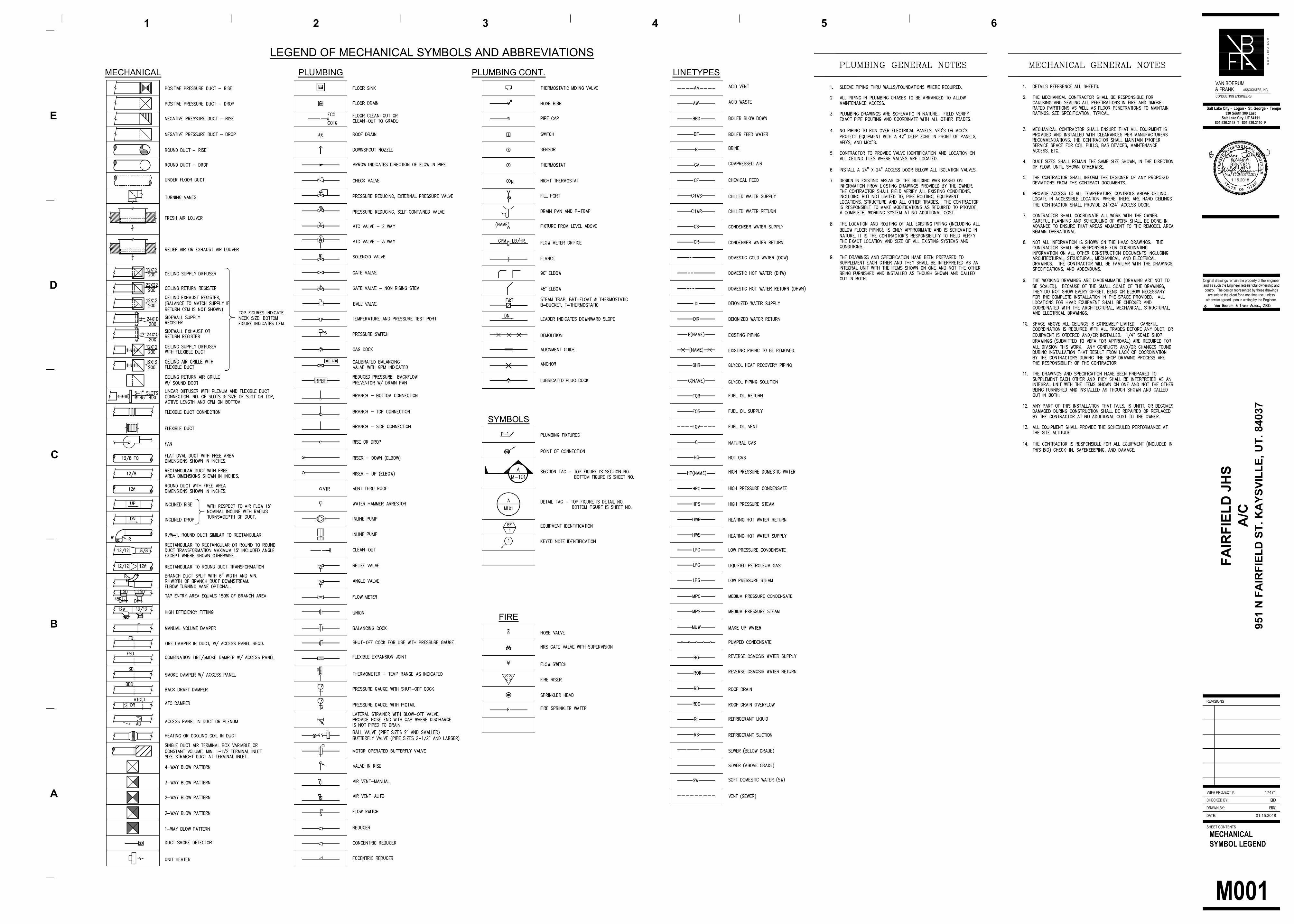
M001
MECHANICAL
SYMBOL LEGEND
LEGEND OF MECHANICAL SYMBOLS AND ABBREVIATIONS
MECHANICAL PLUMBING PLUMBING CONT. LINETYPES
SYMBOLS
FIRE
DATE:
DRAWN BY:
CHECKED BY:
SHEET CONTENTS
REVISIONS
Original drawings remain the property of the Engineer
and as such the Engineer retains total ownership and
control. The design represented by these drawings
are sold to the client for a one time use, unless
otherwise agreed upon in writing by the Engineer.
BL
BD
01.15.2018
A
B
D
E
1 2 3 4 5
W W
W
. V
B
F
A
. C
O
M
VBFA PROJECT #: 17471
330 South 300 East
Salt Lake City, UT 84111
801.530.3148 T 801.530.3150 F
Salt Lake City ▪ Logan ▪ St. George ▪ Tempe
VAN BOERUM
& FRANKASSOCIATES, INC.
CONSULTING ENGINEERS
C
6
FA
IR
FIE
LD
JH
S
A/C
951 N
F
AIR
FIE
LD
S
T. K
AY
SV
IL
LE
, U
T. 84037
EW
EF
LIC
ENSE
D P
ROFESS I ONAL ENGIN
EER
No. 172628-2202
S TA T E O F UTAH
WADE W.BENNION
LIC
ENSE
D P
ROFESS I ONAL ENGIN
EER
No. 15071
S TA T E O F UTAH
B. ELAINEFAWSON1.15.2018
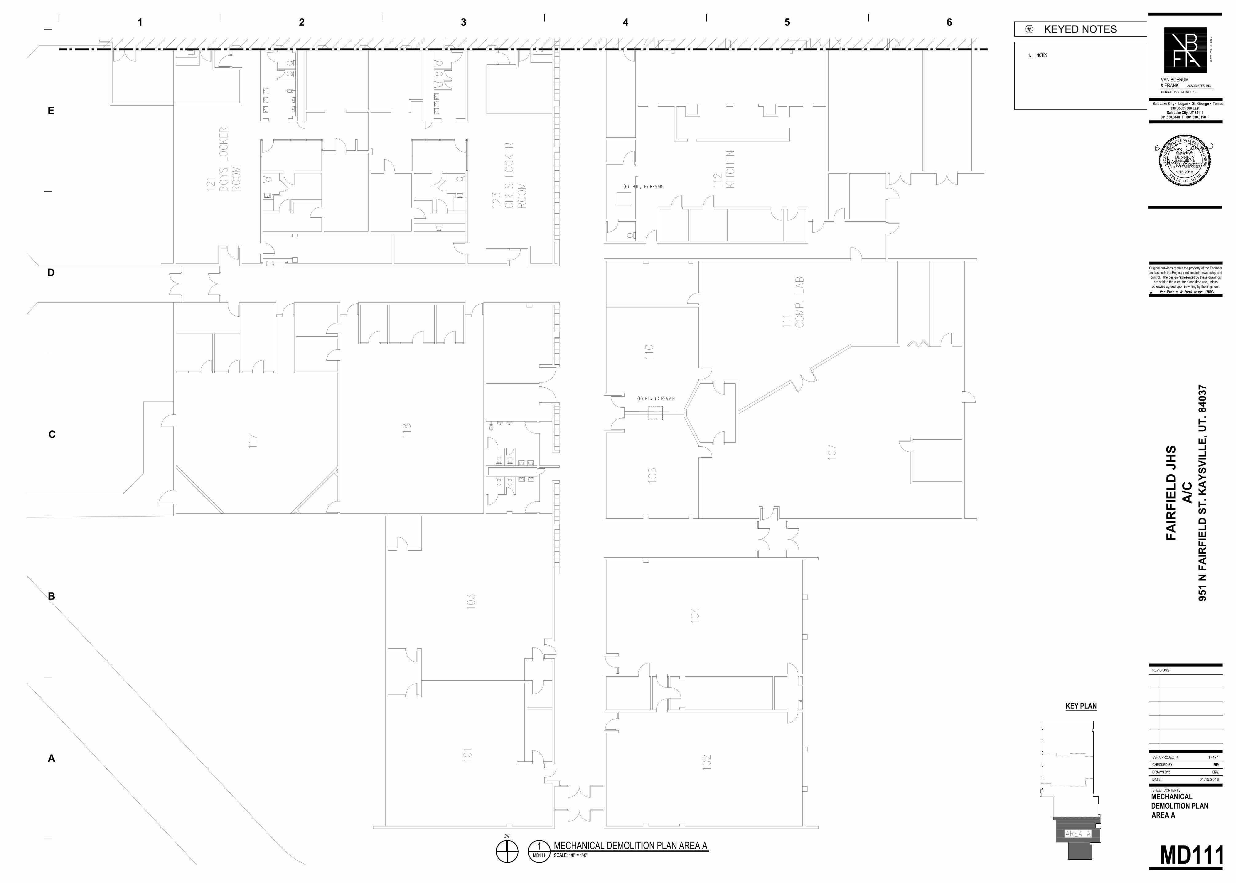
MD111
MECHANICAL
DEMOLITION PLAN
AREA A
MD111 SCALE: 1/8" = 1'-0"
1MECHANICAL DEMOLITION PLAN AREA A
SCALE:
KEYED NOTES
#
KEY PLAN
DATE:
DRAWN BY:
CHECKED BY:
SHEET CONTENTS
REVISIONS
Original drawings remain the property of the Engineer
and as such the Engineer retains total ownership and
control. The design represented by these drawings
are sold to the client for a one time use, unless
otherwise agreed upon in writing by the Engineer.
BL
BD
01.15.2018
A
B
D
E
1 2 3 4 5
W W
W
. V
B
F
A
. C
O
M
VBFA PROJECT #: 17471
330 South 300 East
Salt Lake City, UT 84111
801.530.3148 T 801.530.3150 F
Salt Lake City ▪ Logan ▪ St. George ▪ Tempe
VAN BOERUM
& FRANK ASSOCIATES, INC.
CONSULTING ENGINEERS
C
6
FA
IR
FIE
LD
JH
S
A/C
951 N
F
AIR
FIE
LD
S
T. K
AY
SV
IL
LE
, U
T. 84037
EW
EF
LIC
ENSE
D P
ROFESS I ONAL ENGIN
EER
No. 172628-2202
STA T E O F U TAH
WADE W.BENNION
LIC
ENSE
D P
ROFESS I ONAL ENGIN
EER
No. 15071
STA T E O F U TAH
B. ELAINEFAWSON1.15.2018
MD112
MECHANICAL
DEMOLITION PLAN
AREA B
1MECHANICAL DEMOLITION PLAN AREA B
MD112 SCALE: 1/8" = 1'-0"
KEY PLAN
KEYED NOTES
#
DATE:
DRAWN BY:
CHECKED BY:
SHEET CONTENTS
REVISIONS
Original drawings remain the property of the Engineer
and as such the Engineer retains total ownership and
control. The design represented by these drawings
are sold to the client for a one time use, unless
otherwise agreed upon in writing by the Engineer.
BL
BD
01.15.2018
A
B
D
E
1 2 3 4 5
W W
W
. V
B
F
A
. C
O
M
VBFA PROJECT #: 17471
330 South 300 East
Salt Lake City, UT 84111
801.530.3148 T 801.530.3150 F
Salt Lake City ▪ Logan ▪ St. George ▪ Tempe
VAN BOERUM
& FRANK ASSOCIATES, INC.
CONSULTING ENGINEERS
C
6
FA
IR
FIE
LD
JH
S
A/C
951 N
F
AIR
FIE
LD
S
T. K
AY
SV
IL
LE
, U
T. 84037
EW
EF
LIC
ENSE
D P
ROFESS I ONAL ENGIN
EER
No. 172628-2202
S TA T E O F U TAH
WADE W.BENNION
LIC
ENSE
D P
ROFESS I ONAL ENGIN
EER
No. 15071
S TA T E O F U TAH
B. ELAINEFAWSON1.15.2018

MD113
MECHANICAL
DEMOLITION PLAN
AREA C
1MECHANICAL DEMOLITION PLAN AREA C
SCALE: MD113 SCALE: 1/8" = 1'-0"
KEY PLAN
KEYED NOTES
#
DATE:
DRAWN BY:
CHECKED BY:
SHEET CONTENTS
REVISIONS
Original drawings remain the property of the Engineer
and as such the Engineer retains total ownership and
control. The design represented by these drawings
are sold to the client for a one time use, unless
otherwise agreed upon in writing by the Engineer.
BL
BD
01.15.2018
A
B
D
E
1 2 3 4 5
W W
W
. V
B
F
A
. C
O
M
VBFA PROJECT #: 17471
330 South 300 East
Salt Lake City, UT 84111
801.530.3148 T 801.530.3150 F
Salt Lake City ▪ Logan ▪ St. George ▪ Tempe
VAN BOERUM
& FRANK ASSOCIATES, INC.
CONSULTING ENGINEERS
C
6
FA
IR
FIE
LD
JH
S
A/C
951 N
F
AIR
FIE
LD
S
T. K
AY
SV
IL
LE
, U
T. 84037
EW
EF
LIC
ENSE
D P
ROFESS I ONAL ENGIN
EER
No. 172628-2202
S TA T E O F U TAH
WADE W.BENNION
LIC
ENSE
D P
ROFESS I ONAL ENGIN
EER
No. 15071
S TA T E O F U TAH
B. ELAINEFAWSON1.15.2018
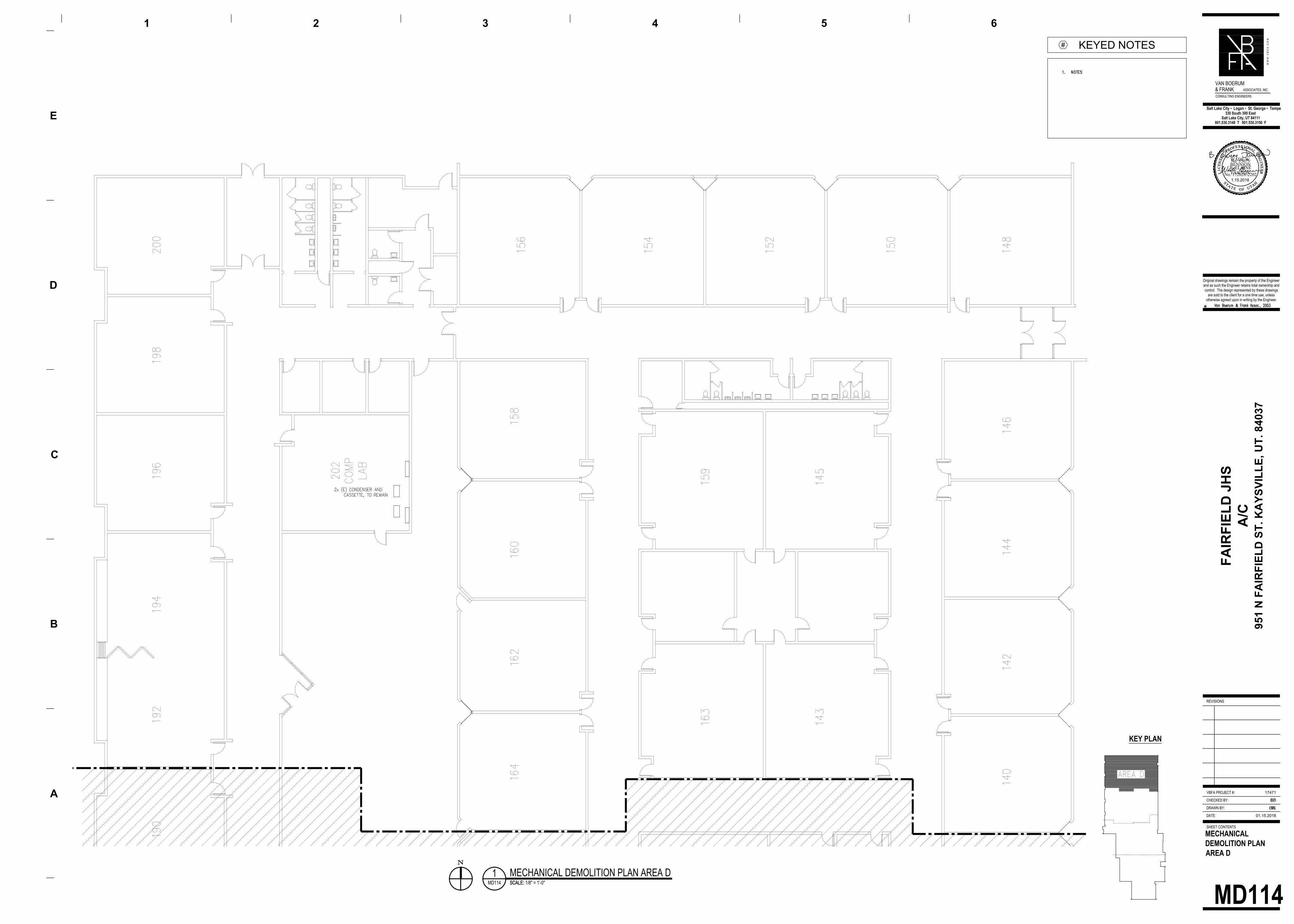
MD114
MECHANICAL
DEMOLITION PLAN
AREA D
1MECHANICAL DEMOLITION PLAN AREA D
SCALE: MD114 SCALE: 1/8" = 1'-0"
KEY PLAN
KEYED NOTES
#
DATE:
DRAWN BY:
CHECKED BY:
SHEET CONTENTS
REVISIONS
Original drawings remain the property of the Engineer
and as such the Engineer retains total ownership and
control. The design represented by these drawings
are sold to the client for a one time use, unless
otherwise agreed upon in writing by the Engineer.
BL
BD
01.15.2018
A
B
D
E
1 2 3 4 5
W W
W
. V
B
F
A
. C
O
M
VBFA PROJECT #: 17471
330 South 300 East
Salt Lake City, UT 84111
801.530.3148 T 801.530.3150 F
Salt Lake City ▪ Logan ▪ St. George ▪ Tempe
VAN BOERUM
& FRANK ASSOCIATES, INC.
CONSULTING ENGINEERS
C
6
FA
IR
FIE
LD
JH
S
A/C
951 N
F
AIR
FIE
LD
S
T. K
AY
SV
IL
LE
, U
T. 84037
EW
EF
LIC
ENSE
D P
ROFESS I ONAL ENGIN
EER
No. 172628-2202
STA T E O F U TAH
WADE W.BENNION
LIC
ENSE
D P
ROFESS I ONAL ENGIN
EER
No. 15071
STA T E O F U TAH
B. ELAINEFAWSON1.15.2018
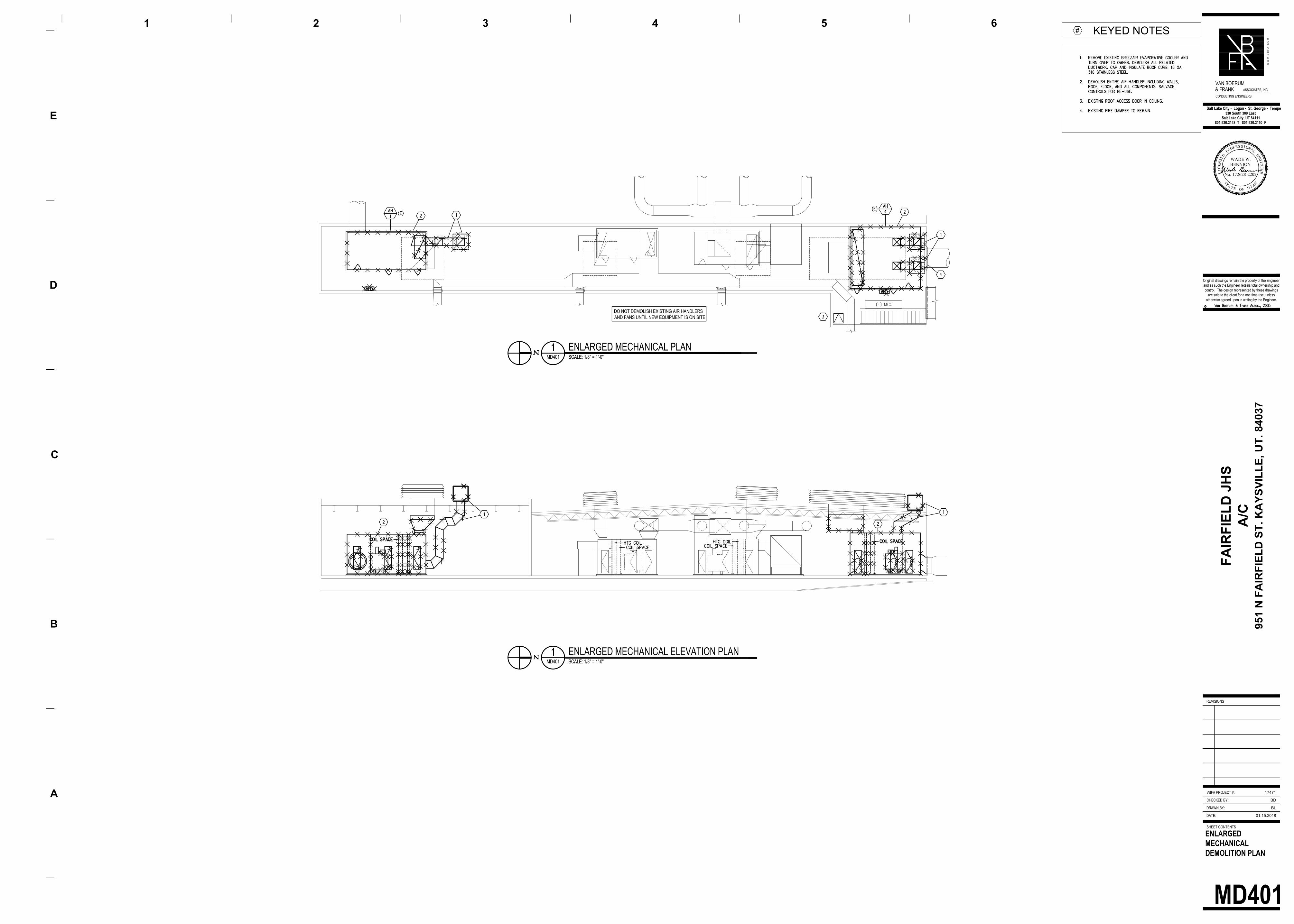
DO NOT DEMOLISH EXISTING AIR HANDLERS
AND FANS UNTIL NEW EQUIPMENT IS ON SITE
MD401
ENLARGED
MECHANICAL
DEMOLITION PLAN
MD401 SCALE: 1/8" = 1'-0"
1ENLARGED MECHANICAL ELEVATION PLAN
SCALE:
DATE:
DRAWN BY:
CHECKED BY:
SHEET CONTENTS
REVISIONS
Original drawings remain the property of the Engineer
and as such the Engineer retains total ownership and
control. The design represented by these drawings
are sold to the client for a one time use, unless
otherwise agreed upon in writing by the Engineer.
BL
BD
01.15.2018
A
B
D
E
1 2 3 4 5
W W
W
. V
B
F
A
. C
O
M
VBFA PROJECT #: 17471
330 South 300 East
Salt Lake City, UT 84111
801.530.3148 T 801.530.3150 F
Salt Lake City ▪ Logan ▪ St. George ▪ Tempe
VAN BOERUM
& FRANKASSOCIATES, INC.
CONSULTING ENGINEERS
C
6
FA
IR
FIE
LD
JH
S
A/C
951 N
F
AIR
FIE
LD
S
T. K
AY
SV
IL
LE
, U
T. 84037
LIC
ENSE
D P
ROFESS I ONAL ENGIN
EER
No. 172628-2202
S TA T E O F U TAH
WADE W.BENNION
KEYED NOTES
#
MD401 SCALE: 1/8" = 1'-0"
1ENLARGED MECHANICAL PLAN
SCALE:
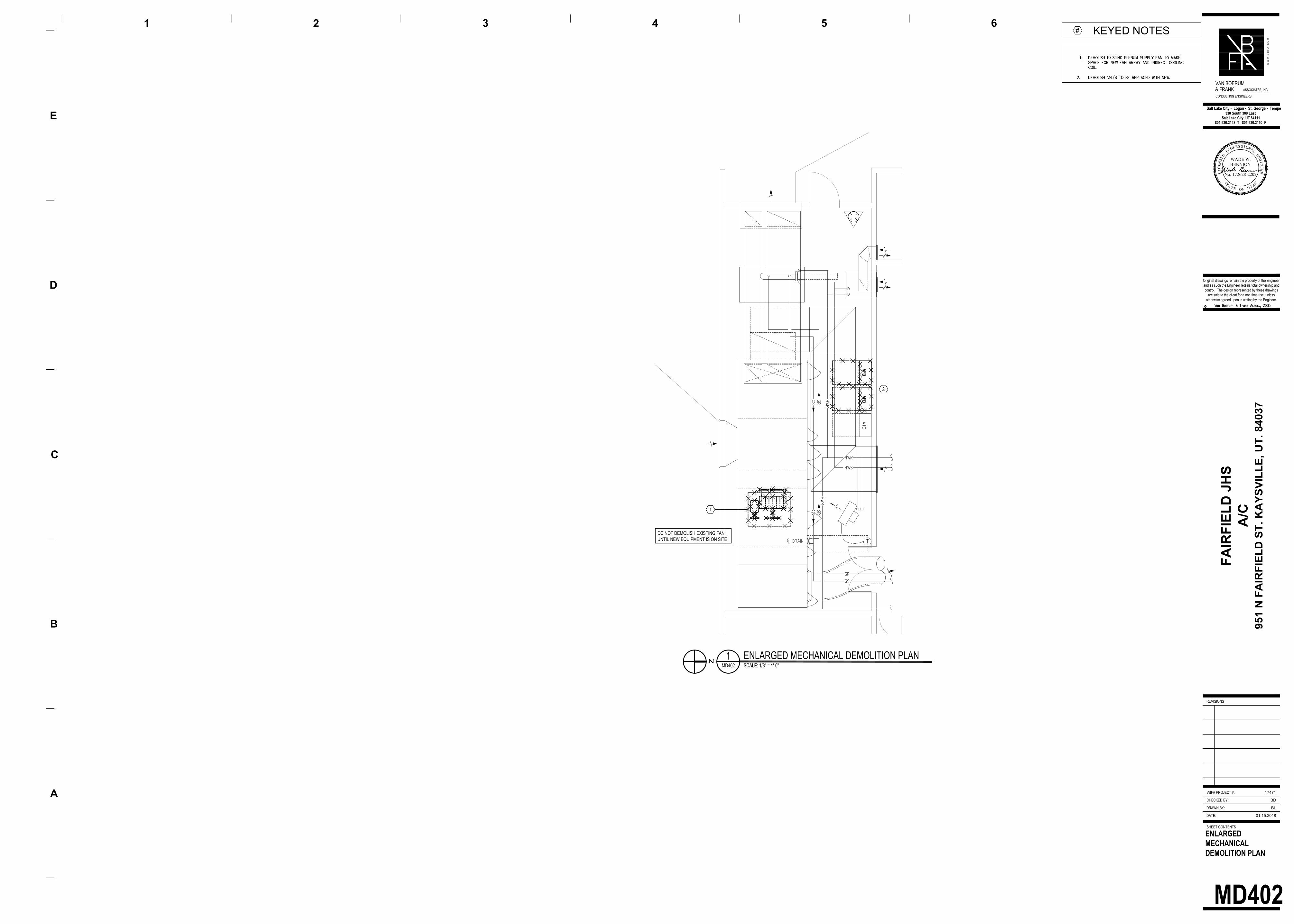
DO NOT DEMOLISH EXISTING FAN
UNTIL NEW EQUIPMENT IS ON SITE
MD402
ENLARGED
MECHANICAL
DEMOLITION PLAN
DATE:
DRAWN BY:
CHECKED BY:
SHEET CONTENTS
REVISIONS
Original drawings remain the property of the Engineer
and as such the Engineer retains total ownership and
control. The design represented by these drawings
are sold to the client for a one time use, unless
otherwise agreed upon in writing by the Engineer.
BL
BD
01.15.2018
A
B
D
E
1 2 3 4 5
W W
W
. V
B
F
A
. C
O
M
VBFA PROJECT #: 17471
330 South 300 East
Salt Lake City, UT 84111
801.530.3148 T 801.530.3150 F
Salt Lake City ▪ Logan ▪ St. George ▪ Tempe
VAN BOERUM
& FRANKASSOCIATES, INC.
CONSULTING ENGINEERS
C
6
FA
IR
FIE
LD
JH
S
A/C
951 N
F
AIR
FIE
LD
S
T. K
AY
SV
IL
LE
, U
T. 84037
LIC
ENSE
D P
ROFESS I ONAL ENGIN
EER
No. 172628-2202
S TA T E O F U TAH
WADE W.BENNION
KEYED NOTES
#
MD402 SCALE: 1/8" = 1'-0"
1ENLARGED MECHANICAL DEMOLITION PLAN
SCALE:
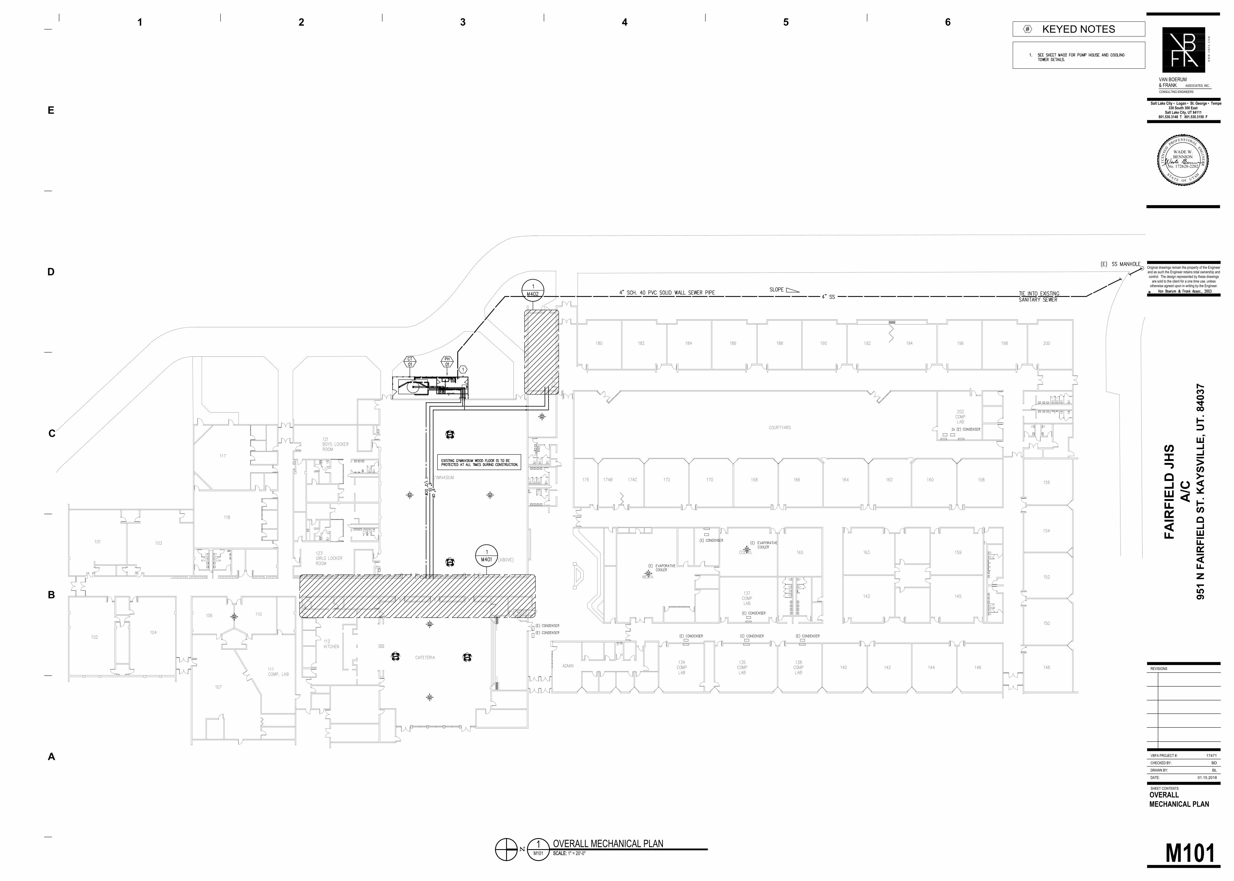
M101
OVERALL
MECHANICAL PLAN
M101 SCALE: 1" = 20'-0"
1OVERALL MECHANICAL PLAN
SCALE:
DATE:
DRAWN BY:
CHECKED BY:
SHEET CONTENTS
REVISIONS
Original drawings remain the property of the Engineer
and as such the Engineer retains total ownership and
control. The design represented by these drawings
are sold to the client for a one time use, unless
otherwise agreed upon in writing by the Engineer.
BL
BD
01.15.2018
A
B
D
E
1 2 3 4 5
W W
W
. V
B
F
A
. C
O
M
VBFA PROJECT #: 17471
330 South 300 East
Salt Lake City, UT 84111
801.530.3148 T 801.530.3150 F
Salt Lake City ▪ Logan ▪ St. George ▪ Tempe
VAN BOERUM
& FRANKASSOCIATES, INC.
CONSULTING ENGINEERS
C
6
FA
IR
FIE
LD
JH
S
A/C
951 N
F
AIR
FIE
LD
S
T. K
AY
SV
IL
LE
, U
T. 84037
LIC
ENSE
D P
ROFESS I ONAL ENGIN
EER
No. 172628-2202
S TA T E O F U TAH
WADE W.BENNION
KEYED NOTES
#

M112
MECHANICAL PLAN
AREA B
1MECHANICAL PLAN AREA B
M112 SCALE: 1/8" = 1'-0"
KEY PLAN
KEYED NOTES
#
DATE:
DRAWN BY:
CHECKED BY:
SHEET CONTENTS
REVISIONS
Original drawings remain the property of the Engineer
and as such the Engineer retains total ownership and
control. The design represented by these drawings
are sold to the client for a one time use, unless
otherwise agreed upon in writing by the Engineer.
BL
BD
01.15.2018
A
B
D
E
1 2 3 4 5
W W
W
. V
B
F
A
. C
O
M
VBFA PROJECT #: 17471
330 South 300 East
Salt Lake City, UT 84111
801.530.3148 T 801.530.3150 F
Salt Lake City ▪ Logan ▪ St. George ▪ Tempe
VAN BOERUM
& FRANKASSOCIATES, INC.
CONSULTING ENGINEERS
C
6
FA
IR
FIE
LD
JH
S
A/C
951 N
F
AIR
FIE
LD
S
T. K
AY
SV
IL
LE
, U
T. 84037
EW
EF
LIC
ENSE
D P
ROFESS I ONAL ENGIN
EER
No. 172628-2202
S TA T E O F UTAH
WADE W.BENNION
LIC
ENSE
D P
ROFESS I ONAL ENGIN
EER
No. 15071
S TA T E O F UTAH
B. ELAINEFAWSON1.15.2018
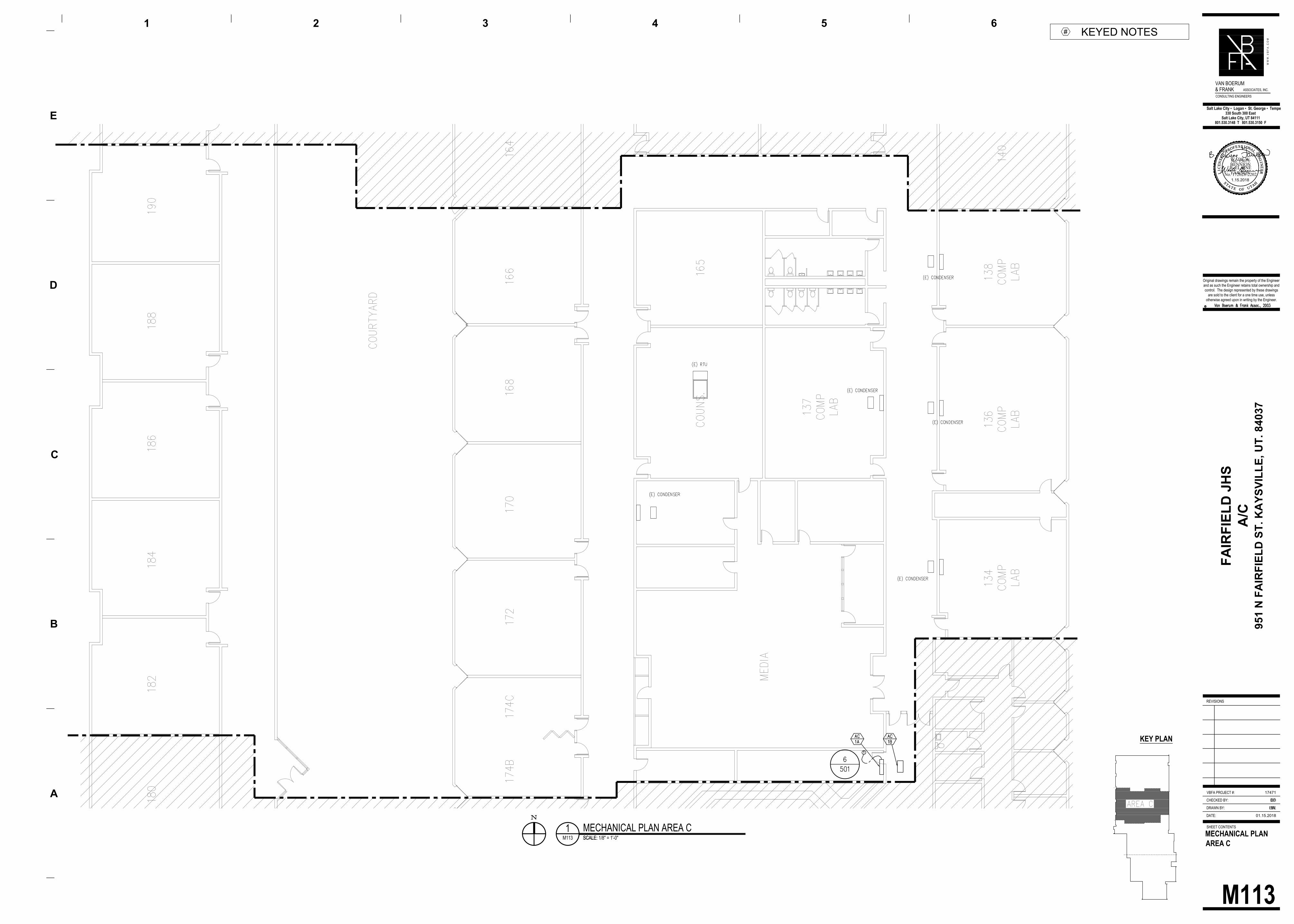
M113
MECHANICAL PLAN
AREA C
1MECHANICAL PLAN AREA C
SCALE: M113 SCALE: 1/8" = 1'-0"
KEY PLAN
KEYED NOTES
#
DATE:
DRAWN BY:
CHECKED BY:
SHEET CONTENTS
REVISIONS
Original drawings remain the property of the Engineer
and as such the Engineer retains total ownership and
control. The design represented by these drawings
are sold to the client for a one time use, unless
otherwise agreed upon in writing by the Engineer.
BL
BD
01.15.2018
A
B
D
E
1 2 3 4 5
W W
W
. V
B
F
A
. C
O
M
VBFA PROJECT #: 17471
330 South 300 East
Salt Lake City, UT 84111
801.530.3148 T 801.530.3150 F
Salt Lake City ▪ Logan ▪ St. George ▪ Tempe
VAN BOERUM
& FRANKASSOCIATES, INC.
CONSULTING ENGINEERS
C
6
FA
IR
FIE
LD
JH
S
A/C
951 N
F
AIR
FIE
LD
S
T. K
AY
SV
IL
LE
, U
T. 84037
EW
EF
LIC
ENSE
D P
ROFESS I ONAL ENGIN
EER
No. 172628-2202
S TA T E O F UTAH
WADE W.BENNION
LIC
ENSE
D P
ROFESS I ONAL ENGIN
EER
No. 15071
S TA T E O F UTAH
B. ELAINEFAWSON1.15.2018

M114
MECHANICAL PLAN
AREA D
1MECHANICAL PLAN AREA D
SCALE: M114 SCALE: 1/8" = 1'-0"
KEY PLAN
KEYED NOTES
#
DATE:
DRAWN BY:
CHECKED BY:
SHEET CONTENTS
REVISIONS
Original drawings remain the property of the Engineer
and as such the Engineer retains total ownership and
control. The design represented by these drawings
are sold to the client for a one time use, unless
otherwise agreed upon in writing by the Engineer.
BL
BD
01.15.2018
A
B
D
E
1 2 3 4 5
W W
W
. V
B
F
A
. C
O
M
VBFA PROJECT #: 17471
330 South 300 East
Salt Lake City, UT 84111
801.530.3148 T 801.530.3150 F
Salt Lake City ▪ Logan ▪ St. George ▪ Tempe
VAN BOERUM
& FRANKASSOCIATES, INC.
CONSULTING ENGINEERS
C
6
FA
IR
FIE
LD
JH
S
A/C
951 N
F
AIR
FIE
LD
S
T. K
AY
SV
IL
LE
, U
T. 84037
EW
EF
LIC
ENSE
D P
ROFESS I ONAL ENGIN
EER
No. 172628-2202
S TA T E O F UTAH
WADE W.BENNION
LIC
ENSE
D P
ROFESS I ONAL ENGIN
EER
No. 15071
S TA T E O F UTAH
B. ELAINEFAWSON1.15.2018
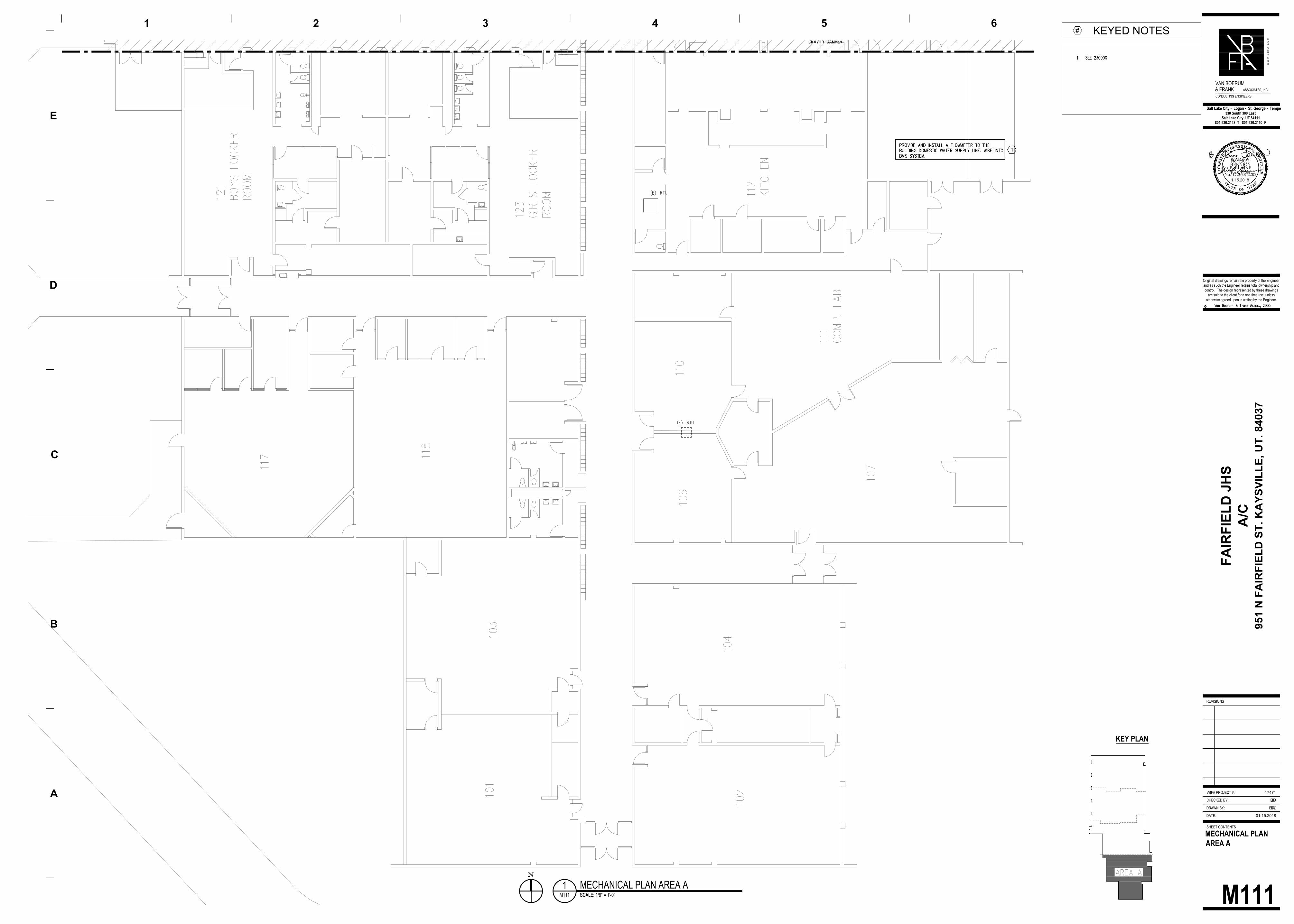
M111
MECHANICAL PLAN
AREA A
M111 SCALE: 1/8" = 1'-0"
1MECHANICAL PLAN AREA A
SCALE:
KEYED NOTES
#
KEY PLAN
DATE:
DRAWN BY:
CHECKED BY:
SHEET CONTENTS
REVISIONS
Original drawings remain the property of the Engineer
and as such the Engineer retains total ownership and
control. The design represented by these drawings
are sold to the client for a one time use, unless
otherwise agreed upon in writing by the Engineer.
BL
BD
01.15.2018
A
B
D
E
1 2 3 4 5
W W
W
. V
B
F
A
. C
O
M
VBFA PROJECT #: 17471
330 South 300 East
Salt Lake City, UT 84111
801.530.3148 T 801.530.3150 F
Salt Lake City ▪ Logan ▪ St. George ▪ Tempe
VAN BOERUM
& FRANK ASSOCIATES, INC.
CONSULTING ENGINEERS
C
6
FA
IR
FIE
LD
JH
S
A/C
951 N
F
AIR
FIE
LD
S
T. K
AY
SV
IL
LE
, U
T. 84037
EW
EF
LIC
ENSE
D P
ROFESS I ONAL ENGIN
EER
No. 172628-2202
STA T E O F U TAH
WADE W.BENNION
LIC
ENSE
D P
ROFESS I ONAL ENGIN
EER
No. 15071
STA T E O F U TAH
B. ELAINEFAWSON1.15.2018
DO NOT DEMOLISH EXISTING FAN
UNTIL NEW EQUIPMENT IS ON SITE
A
M-402
M402
ENLARGED
MECHANICAL PLAN
DATE:
DRAWN BY:
CHECKED BY:
SHEET CONTENTS
REVISIONS
Original drawings remain the property of the Engineer
and as such the Engineer retains total ownership and
control. The design represented by these drawings
are sold to the client for a one time use, unless
otherwise agreed upon in writing by the Engineer.
BL
BD
01.15.2018
A
B
D
E
1 2 3 4 5
W W
W
. V
B
F
A
. C
O
M
VBFA PROJECT #: 17471
330 South 300 East
Salt Lake City, UT 84111
801.530.3148 T 801.530.3150 F
Salt Lake City ▪ Logan ▪ St. George ▪ Tempe
VAN BOERUM
& FRANKASSOCIATES, INC.
CONSULTING ENGINEERS
C
6
FA
IR
FIE
LD
JH
S
A/C
951 N
F
AIR
FIE
LD
S
T. K
AY
SV
IL
LE
, U
T. 84037
LIC
ENSE
D P
ROFESS I ONAL ENGIN
EER
No. 172628-2202
S TAT E O F U TAH
WADE W.BENNION
M402 SCALE: 1/4" = 1'-0"
1ENLARGED MECHANICAL PLAN
SCALE:
M402 SCALE: 1/4" = 1'-0"
2ENLARGED MECHANICAL PLAN PUMP HOUSE
SCALE:
KEYED NOTES
#
M402 SCALE: 1/4" = 1'-0"
0' 4' 8'
APUMP HOUSE & COOLING TOWER ELEVATION
SCALE:

DO NOT DEMOLISH EXISTING AIR HANDLERS
AND FANS UNTIL NEW EQUIPMENT IS ON SITE
M401
ENLARGED
MECHANICAL PLAN
M401 SCALE: 1/8" = 1'-0"
1ENLARGED MECHANICAL ELEVATION PLAN
SCALE:
DATE:
DRAWN BY:
CHECKED BY:
SHEET CONTENTS
REVISIONS
Original drawings remain the property of the Engineer
and as such the Engineer retains total ownership and
control. The design represented by these drawings
are sold to the client for a one time use, unless
otherwise agreed upon in writing by the Engineer.
BL
BD
01.15.2018
A
B
D
E
1 2 3 4 5
W W
W
. V
B
F
A
. C
O
M
VBFA PROJECT #: 17471
330 South 300 East
Salt Lake City, UT 84111
801.530.3148 T 801.530.3150 F
Salt Lake City ▪ Logan ▪ St. George ▪ Tempe
VAN BOERUM
& FRANKASSOCIATES, INC.
CONSULTING ENGINEERS
C
6
FA
IR
FIE
LD
JH
S
A/C
951 N
F
AIR
FIE
LD
S
T. K
AY
SV
IL
LE
, U
T. 84037
LIC
ENSE
D P
ROFESS I ONAL ENGIN
EER
No. 172628-2202
S TA T E O F U TAH
WADE W.BENNION
M401 SCALE: 1/8" = 1'-0"
1ENLARGED MECHANICAL PLAN
SCALE:
KEYED NOTES
#
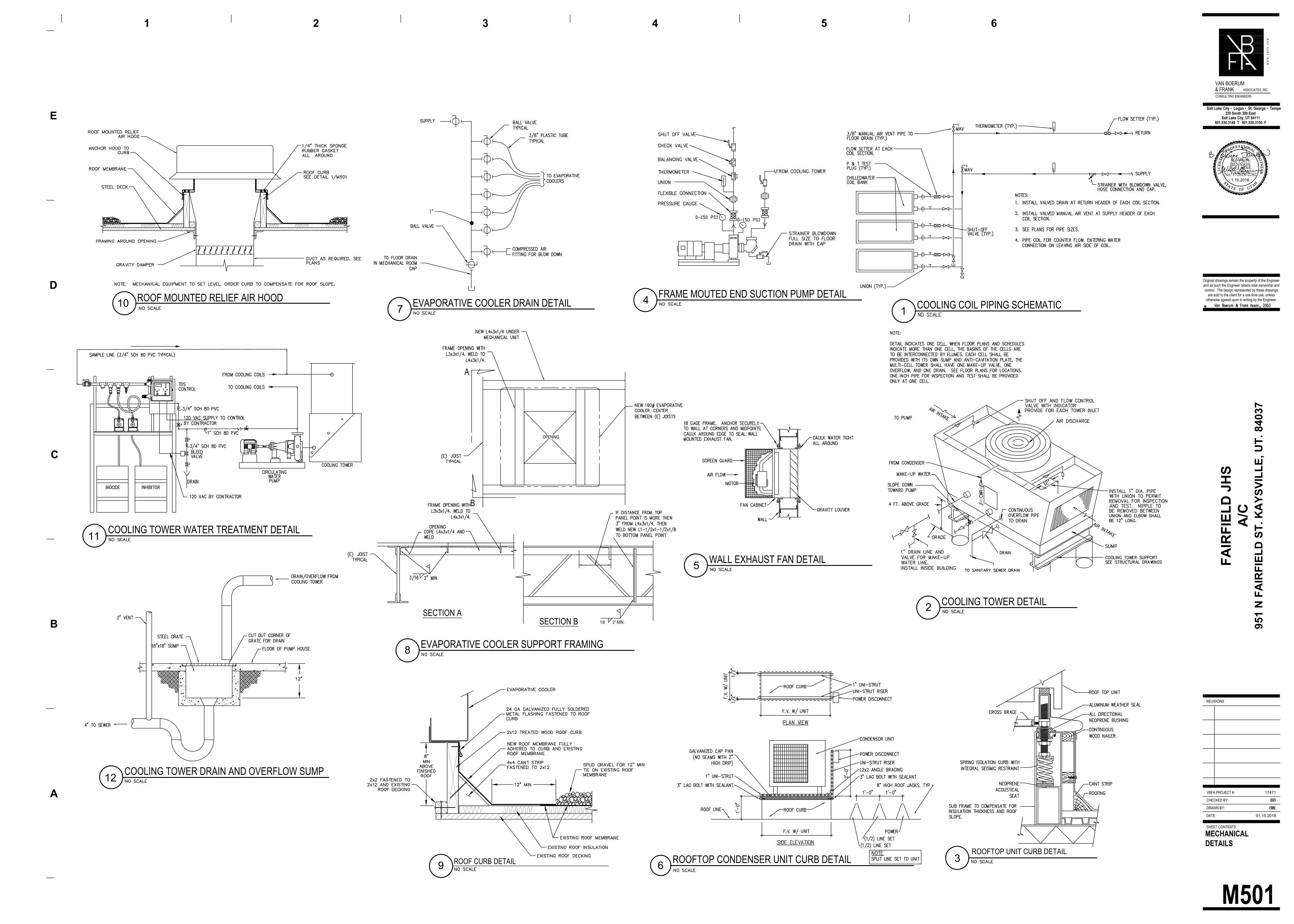
FRAME MOUTED END SUCTION PUMP DETAIL
3
4
COOLING TOWER DETAIL
2
COOLING COIL PIPING SCHEMATIC
1
WALL EXHAUST FAN DETAIL
5
6
ROOFTOP CONDENSER UNIT CURB DETAIL
EVAPORATIVE COOLER DRAIN DETAIL
7
ROOF CURB DETAIL
OPENING
B
SECTION A
SECTION B2" MIN.1/8
A
EVAPORATIVE COOLER SUPPORT FRAMING
8
ROOF MOUNTED RELIEF AIR HOOD
10
ROOFTOP UNIT CURB DETAIL
9
COOLING TOWER WATER TREATMENT DETAIL
11
COOLING TOWER DRAIN AND OVERFLOW SUMP
12
M501
MECHANICAL
DETAILS
DATE:
DRAWN BY:
CHECKED BY:
SHEET CONTENTS
REVISIONS
Original drawings remain the property of the Engineer
and as such the Engineer retains total ownership and
control. The design represented by these drawings
are sold to the client for a one time use, unless
otherwise agreed upon in writing by the Engineer.
BL
BD
01.15.2018
A
B
D
E
1 2 3 4 5
W W
W
. V
B
F
A
. C
O
M
VBFA PROJECT #: 17471
330 South 300 East
Salt Lake City, UT 84111
801.530.3148 T 801.530.3150 F
Salt Lake City ▪ Logan ▪ St. George ▪ Tempe
VAN BOERUM
& FRANK ASSOCIATES, INC.
CONSULTING ENGINEERS
C
6
FA
IR
FIE
LD
JH
S
A/C
951 N
F
AIR
FIE
LD
S
T. K
AY
SV
IL
LE
, U
T. 84037
EW
EF
LIC
ENSE
D P
ROFE SS I ONAL ENGIN
EER
No. 172628-2202
STAT E O F U TAH
WADE W.BENNION
LIC
ENSE
D P
ROFE SS I ONAL ENGIN
EER
No. 15071
STAT E O F U TAH
B. ELAINEFAWSON1.15.2018
M601
MECHANICAL
SCHEDULES
DATE:
DRAWN BY:
CHECKED BY:
SHEET CONTENTS
REVISIONS
Original drawings remain the property of the Engineer
and as such the Engineer retains total ownership and
control. The design represented by these drawings
are sold to the client for a one time use, unless
otherwise agreed upon in writing by the Engineer.
BL
BD
01.15.2018
A
B
D
E
1 2 3 4 5
W W
W
. V
B
F
A
. C
O
M
VBFA PROJECT #: 17471
330 South 300 East
Salt Lake City, UT 84111
801.530.3148 T 801.530.3150 F
Salt Lake City ▪ Logan ▪ St. George ▪ Tempe
VAN BOERUM
& FRANKASSOCIATES, INC.
CONSULTING ENGINEERS
C
6
FA
IR
FIE
LD
JH
S
A/C
951 N
F
AIR
FIE
LD
S
T. K
AY
SV
IL
LE
, U
T. 84037
EW
EF
LIC
ENSE
D P
ROFESS I ONAL ENGIN
EER
No. 172628-2202
S TAT E O F U TAH
WADE W.BENNION
LIC
ENSE
D P
ROFESS I ONAL ENGIN
EER
No. 15071
S TAT E O F U TAH
B. ELAINEFAWSON1.15.2018
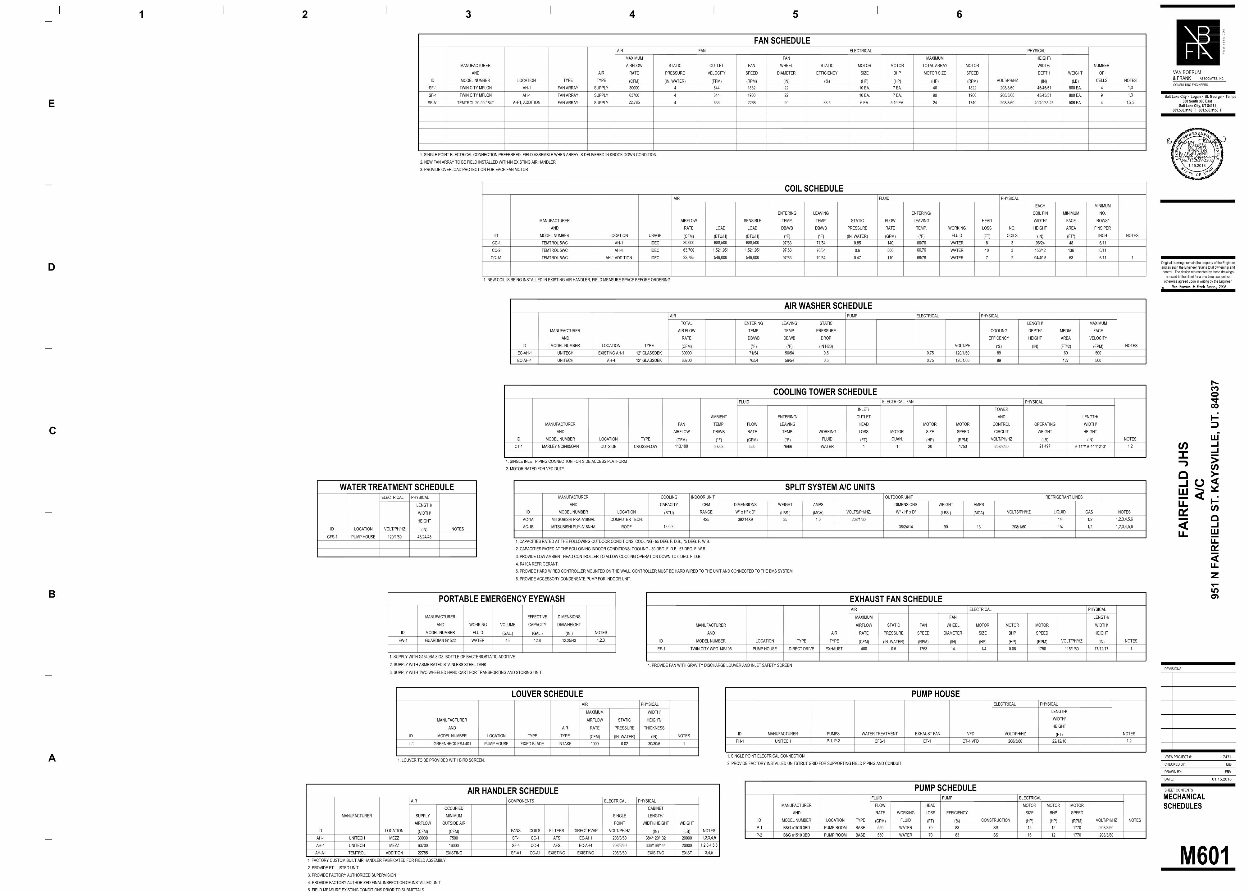
AIR HANDLER SCHEDULE
AIR COMPONENTS ELECTRICAL PHYSICAL
OCCUPIED CABINET
MANUFACTURER SUPPLY MINIMUM SINGLE LENGTH/
AIRFLOW OUTSIDE AIR POINT WIDTH/HEIGHT WEIGHT
ID LOCATION
(CFM) (CFM)
FANS COILS FILTERS DIRECT EVAP VOLT/PH/HZ
(IN) (LB)
NOTES
AH-1 UNITECH MEZZ 30000 7500 SF-1 CC-1 AFS EC-AH1 208/3/60 384/120/132 200001,2,3,4,5
AH-4 UNITECH MEZZ 63700 16000 SF-4 CC-4 AFS EC-AH4 208/3/60 336/168/144 200001,2,3,4,5,6
AH-A1 TEMTROL ADDITION 22785 EXISTING SF-A1 CC-A1 EXISTING EXISTING 208/3/60 EXISITNG EXIST3,4,5
1. FACTORY CUSTOM BUILT AIR HANDLER FABRICATED FOR FIELD ASSEMBLY.
2. PROVIDE ETL LISTED UNIT
3. PROVIDE FACTORY AUTHORIZED SUPERVISION
4. PROVIDE FACTORY AUTHORIZED FINAL INSPECTION OF INSTALLED UNIT
5. FIELD MEASURE EXISTING CONDITIONS PRIOR TO SUBMITTALS
FAN SCHEDULE
AIR FAN ELECTRICAL PHYSICAL
MAXIMUM FAN MAXIMUM HEIGHT/
MANUFACTURER AIRFLOW STATIC OUTLET FAN WHEEL STATIC MOTOR MOTOR TOTAL ARRAY MOTOR WIDTH/ NUMBER
AND AIR RATE PRESSURE VELOCITY SPEED DIAMETER EFFICIENCY SIZE BHP MOTOR SIZE SPEED DEPTH WEIGHT OF
ID MODEL NUMBER LOCATION TYPE TYPE
(CFM) (IN. WATER) (FPM) (RPM) (IN) (%) (HP) (HP) (HP) (RPM)
VOLT/PH/HZ
(IN) (LB)
CELLS NOTES
SF-1 TWIN CITY MPLQN AH-1 FAN ARRAY SUPPLY 30000 4 644 1882 22 10 EA. 7 EA. 40 1822 208/3/60 45/45/51 800 EA. 41,3
SF-4 TWIN CITY MPLQN AH-4 FAN ARRAY SUPPLY 63700 4 644 1900 22 10 EA. 7 EA. 90 1900 208/3/60 45/45/51 800 EA. 91,3
SF-A1 TEMTROL 20-90-184TAH-1, ADDITION
FAN ARRAY SUPPLY22,785
4 633 2268 20 88.5 6 EA. 5.19 EA. 24 1740 208/3/60 40/40/35.25 506 EA. 41,2,3
1. SINGLE POINT ELECTRICAL CONNECTION PREFERRED. FIELD ASSEMBLE WHEN ARRAY IS DELIVERED IN KNOCK DOWN CONDITION.
2. NEW FAN ARRAY TO BE FIELD INSTALLED WITH-IN EXISTING AIR HANDLER
3. PROVIDE OVERLOAD PROTECTION FOR EACH FAN MOTOR
AIR WASHER SCHEDULE
AIR PUMP ELECTRICAL PHYSICAL
TOTAL ENTERING LEAVING STATIC LENGTH/ MAXIMUM
MANUFACTURER AIR FLOW TEMP. TEMP. PRESSURE COOLING DEPTH/ MEDIA FACE
AND RATE DB/WB DB/WB DROP EFFICENCY HEIGHT AREA VELOCITY
ID MODEL NUMBER LOCATION TYPE
(CFM) (°F) (°F) (IN H20)
VOLT/PH
(%) (IN) (FT^2) (FPM)
NOTES
EC-AH-1 UNITECH EXISTING AH-1 12" GLASSDEK 30000 71/54 56/54 0.5 0.75 120/1/60 89 60 500
EC-AH-4 UNITECH AH-4 12" GLASSDEK 63700 70/54 56/54 0.5 0.75 120/1/60 89 127 500
COIL SCHEDULE
AIR FLUID PHYSICAL
EACH MINIMUM
ENTERING LEAVING ENTERING/ COIL FIN MINIMUM NO.
MANUFACTURER AIRFLOW SENSIBLE TEMP. TEMP. STATIC FLOW LEAVING HEAD WIDTH/ FACE ROWS/
AND RATE LOAD LOAD DB/WB DB/WB PRESSURE RATE TEMP. WORKING LOSS NO. HEIGHT AREA FINS PER
ID MODEL NUMBER LOCATION USAGE
(CFM) (BTU/H) (BTU/H) (°F) (°F) (IN. WATER) (GPM) (°F)
FLUID
(FT)
COILS
(IN) (FT²)
INCH NOTES
CC-1 TEMTROL 5WC AH-1 IDEC30,000 688,500 688,500
97/63 71/54 0.85 140 66/76 WATER 8 3 96/24 48 6/11
CC-2 TEMTROL 5WC AH-4 IDEC63,700 1,521,951 1,521,951 97,63
70/54 0.6 30066,76
WATER 10 3 156/42 136 6/11
CC-1A TEMTROL 5WC AH-1 ADDITION IDEC22,785 549,000 549,000
97/63 70/54 0.47 110 66/76 WATER 7 2 94/40.5 53 6/11 1
1. NEW COIL IS BEING INSTALLED IN EXISTING AIR HANDLER, FIELD MEASURE SPACE BEFORE ORDERING
COOLING TOWER SCHEDULE
FLUIDELECTRICAL, FAN
PHYSICAL
INLET/ TOWER
AMBIENT ENTERING/ OUTLET AND LENGTH/
MANUFACTURER FAN TEMP. FLOW LEAVING HEAD MOTOR MOTOR CONTROL OPERATING WIDTH/
AND AIRFLOW DB/WB RATE TEMP. WORKING LOSS MOTOR SIZE SPEED CIRCUIT WEIGHT HEIGHT
ID MODEL NUMBER LOCATION TYPE
(CFM) (°F) (GPM) (°F)
FLUID
(FT)
QUAN.
(HP) (RPM)
VOLT/PH/HZ
(LB) (IN)
NOTES
CT-1 MARLEY NC8405QAN OUTSIDE CROSSFLOW113,100
97/63 550 76/66 WATER 1 1 20 1750 208/3/6021,497
9'-11"/19'-11"/12'-0"1,2
1. SINGLE INLET PIPING CONNECTION FOR SIDE ACCESS PLATFORM
2. MOTOR RATED FOR VFD DUTY.
PORTABLE EMERGENCY EYEWASH
MANUFACTURER EFFECTIVE DIMENSIONS
AND WORKING VOLUME CAPACITY DIAM/HEIGHT
ID MODEL NUMBER FLUID
(GAL.) (GAL.) (IN.)
NOTES
EW-1 GUARDIAN G1522 WATER 15 12.8 12.25/431,2,3
1. SUPPLY WITH G1540BA 8 OZ. BOTTLE OF BACTERIOSTATIC ADDITIVE
2. SUPPLY WITH ASME RATED STAINLESS STEEL TANK
3. SUPPLY WITH TWO WHEELED HAND CART FOR TRANSPORTING AND STORING UNIT.
EXHAUST FAN SCHEDULE
AIR ELECTRICAL PHYSICAL
MAXIMUM FAN LENGTH/
MANUFACTURER AIRFLOW STATIC FAN WHEEL MOTOR MOTOR MOTOR WIDTH/
AND AIR RATE PRESSURE SPEED DIAMETER SIZE BHP SPEED HEIGHT
ID MODEL NUMBER LOCATION TYPE TYPE
(CFM) (IN. WATER) (RPM) (IN) (HP) (HP) (RPM)
VOLT/PH/HZ
(IN)
NOTES
EF-1 TWIN CITY WPD 14B105 PUMP HOUSE DIRECT DRIVE EXHAUST 400 0.5 1753 14 1/4 0.08 1750 115/1/60 17/12/17 1
1. PROVIDE FAN WITH GRAVITY DISCHARGE LOUVER AND INLET SAFETY SCREEN
LOUVER SCHEDULE
AIR PHYSICAL
MAXIMUM WIDTH/
MANUFACTURER AIRFLOW STATIC HEIGHT/
AND AIR RATE PRESSURE THICKNESS
ID MODEL NUMBER LOCATION TYPE TYPE
(CFM) (IN. WATER) (IN)
NOTES
L-1 GREENHECK ESJ-401 PUMP HOUSE FIXED BLADE INTAKE 1000 0.02 30/30/6 1
1. LOUVER TO BE PROVIDED WITH BIRD SCREEN.
PUMP SCHEDULE
FLUID PUMP ELECTRICAL
MANUFACTURER FLOW HEAD MOTOR MOTOR MOTOR
AND RATE WORKING LOSS EFFICIENCY SIZE BHP SPEED
ID MODEL NUMBER LOCATION TYPE
(GPM)
FLUID
(FT) (%)
CONSTRUCTION
(HP) (HP) (RPM)
VOLT/PH/HZ NOTES
P-1 B&G e1510 3BD PUMP ROOM BASE 550 WATER 70 83 SS 15 12 1770 208/3/60
P-2 B&G e1510 3BD PUMP ROOM BASE 550 WATER 70 83 SS 15 12 1770 208/3/60
PUMP HOUSE
ELECTRICAL PHYSICAL
LENGTH/
WIDTH/
HEIGHT
ID MANUFACTURER PUMPS WATER TREATMENT EXHAUST FAN VFD VOLT/PH/HZ
(FT)
NOTES
PH-1 UNITECHP-1, P-2
CFS-1 EF-1 CT-1 VFD 208/3/60 22/12/101,2
1. SINGLE POINT ELECTRICAL CONNECTION
2. PROVIDE FACTORY INSTALLED UNITSTRUT GRID FOR SUPPORTING FIELD PIPING AND CONDUIT.
SPLIT SYSTEM A/C UNITS
MANUFACTURER COOLING INDOOR UNIT OUTDOOR UNIT REFRIGERANT LINES
AND CAPACITY CFM DIMENSIONS WEIGHT AMPS DIMENSIONS WEIGHT AMPS
ID MODEL NUMBER LOCATION
(BTU)
RANGE W" x H" x D"
(LBS.) (MCA)
VOLTS/PH/HZ. W" x H" x D"
(LBS.) (MCA)
VOLTS/PH/HZ. LIQUID GAS NOTES
AC-1A MITSUBISHI PKA-A18GAL COMPUTER TECH. 425 39X14X9 35 1.0 208/1/60 1/4 1/21,2,3,4,5,6
AC-1B MITSUBISHI PUY-A18NHA ROOF18,000
38/24/14 90 13 208/1/60 1/4 1/21,2,3,4,5,6
1. CAPACITIES RATED AT THE FOLLOWING OUTDOOR CONDITIONS: COOLING - 95 DEG. F. D.B., 75 DEG. F. W.B.
2. CAPACITIES RATED AT THE FOLLOWING INDOOR CONDITIONS: COOLING - 80 DEG. F. D.B., 67 DEG. F. W.B.
3. PROVIDE LOW AMBIENT HEAD CONTROLLER TO ALLOW COOLING OPERATION DOWN TO 0 DEG. F. D.B.
4. R410A REFRIGERANT.
5. PROVIDE HARD WIRED CONTROLLER MOUNTED ON THE WALL, CONTROLLER MUST BE HARD WIRED TO THE UNIT AND CONNECTED TO THE BMS SYSTEM.
6. PROVIDE ACCESSORY CONDENSATE PUMP FOR INDOOR UNIT.
WATER TREATMENT SCHEDULE
ELECTRICAL PHYSICAL
LENGTH/
WIDTH/
HEIGHT
ID LOCATION VOLT/PH/HZ
(IN)
NOTES
CFS-1 PUMP HOUSE 120/1/60 48/24/48
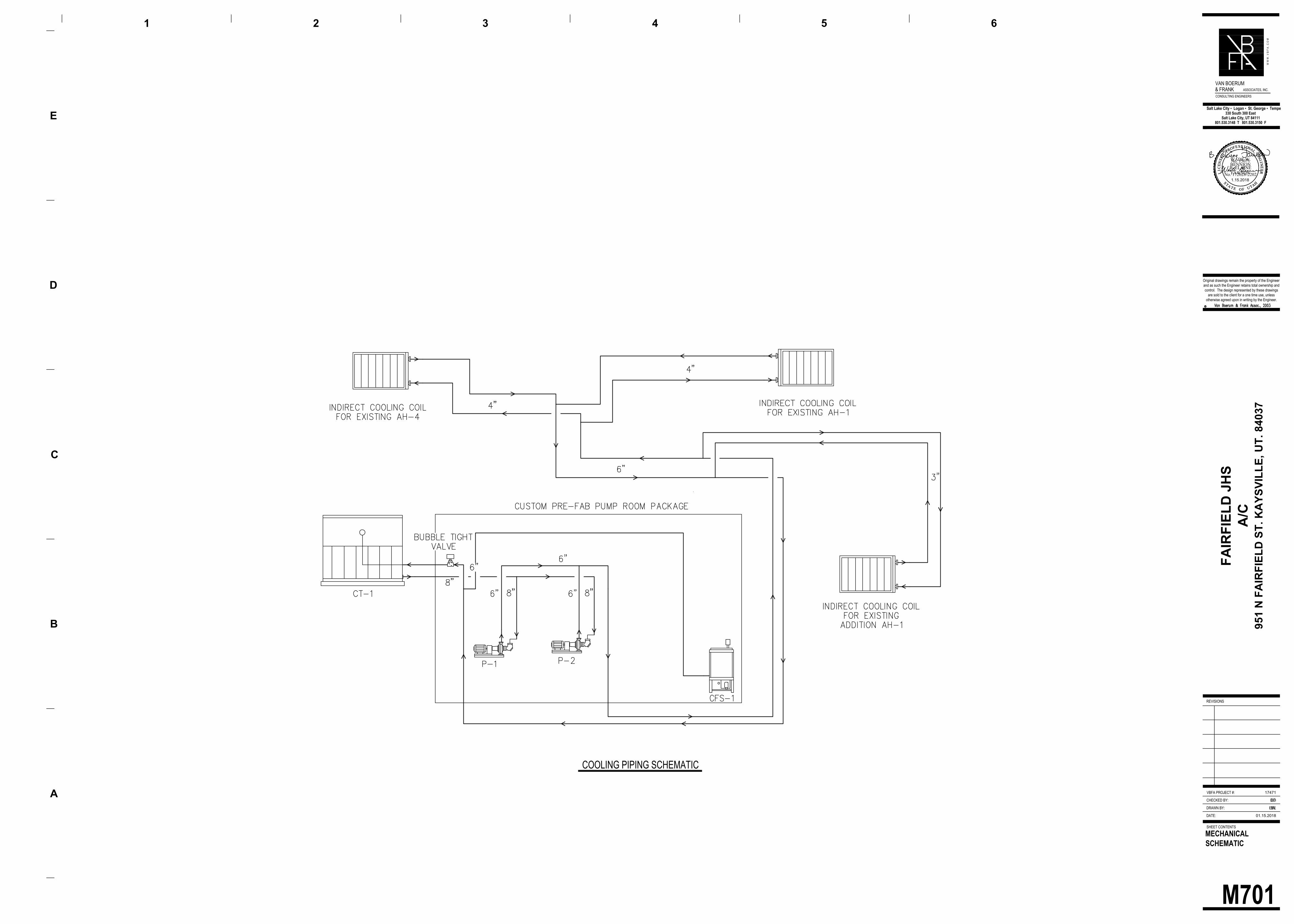
M701
MECHANICAL
SCHEMATIC
DATE:
DRAWN BY:
CHECKED BY:
SHEET CONTENTS
REVISIONS
Original drawings remain the property of the Engineer
and as such the Engineer retains total ownership and
control. The design represented by these drawings
are sold to the client for a one time use, unless
otherwise agreed upon in writing by the Engineer.
BL
BD
01.15.2018
A
B
D
E
1 2 3 4 5
W W
W
. V
B
F
A
. C
O
M
VBFA PROJECT #: 17471
330 South 300 East
Salt Lake City, UT 84111
801.530.3148 T 801.530.3150 F
Salt Lake City ▪ Logan ▪ St. George ▪ Tempe
VAN BOERUM
& FRANKASSOCIATES, INC.
CONSULTING ENGINEERS
C
6
FA
IR
FIE
LD
JH
S
A/C
951 N
F
AIR
FIE
LD
S
T. K
AY
SV
IL
LE
, U
T. 84037
EW
EF
LIC
ENSE
D P
ROFESS I ONAL ENGIN
EER
No. 172628-2202
S TA T E O F U TAH
WADE W.BENNION
LIC
ENSE
D P
ROFESS I ONAL ENGIN
EER
No. 15071
S TA T E O F U TAH
B. ELAINEFAWSON1.15.2018
COOLING PIPING SCHEMATIC

EG001
ELECTRICAL
GENERAL
DATE:
DRAWN BY:
CHECKED BY:
SHEET CONTENTS
REVISIONS
Original drawings remain the property of the Engineer
and as such the Engineer retains total ownership and
control. The design represented by these drawings
are sold to the client for a one time use, unless
otherwise agreed upon in writing by the Engineer.
01.15.2018
A
B
D
E
1 2 3 4 5
W W
W
. V
B
F
A
. C
O
M
VBFA PROJECT #: 17471
330 South 300 East
Salt Lake City, UT 84111
801.530.3148 T 801.530.3150 F
Salt Lake City ▪ Logan ▪ St. George ▪ Tempe
VAN BOERUM
& FRANKASSOCIATES, INC.
CONSULTING ENGINEERS
C
6
FA
IR
FIE
LD
JH
S
A/C
951 N
F
AIR
FIE
LD
S
T. K
AY
SV
IL
LE
, U
T. 84037
EW
EF
LIC
ENSE
D P
ROFESS I ONAL ENGIN
EER
No. 15071
S TA T E O F U TAH
B. ELAINEFAWSON1.15.2018
Sheet List Table
GENERAL NOTES
”
”
ELECTRICAL SYMBOL SCHEDULE
ABBREVIATIONS
NOTES
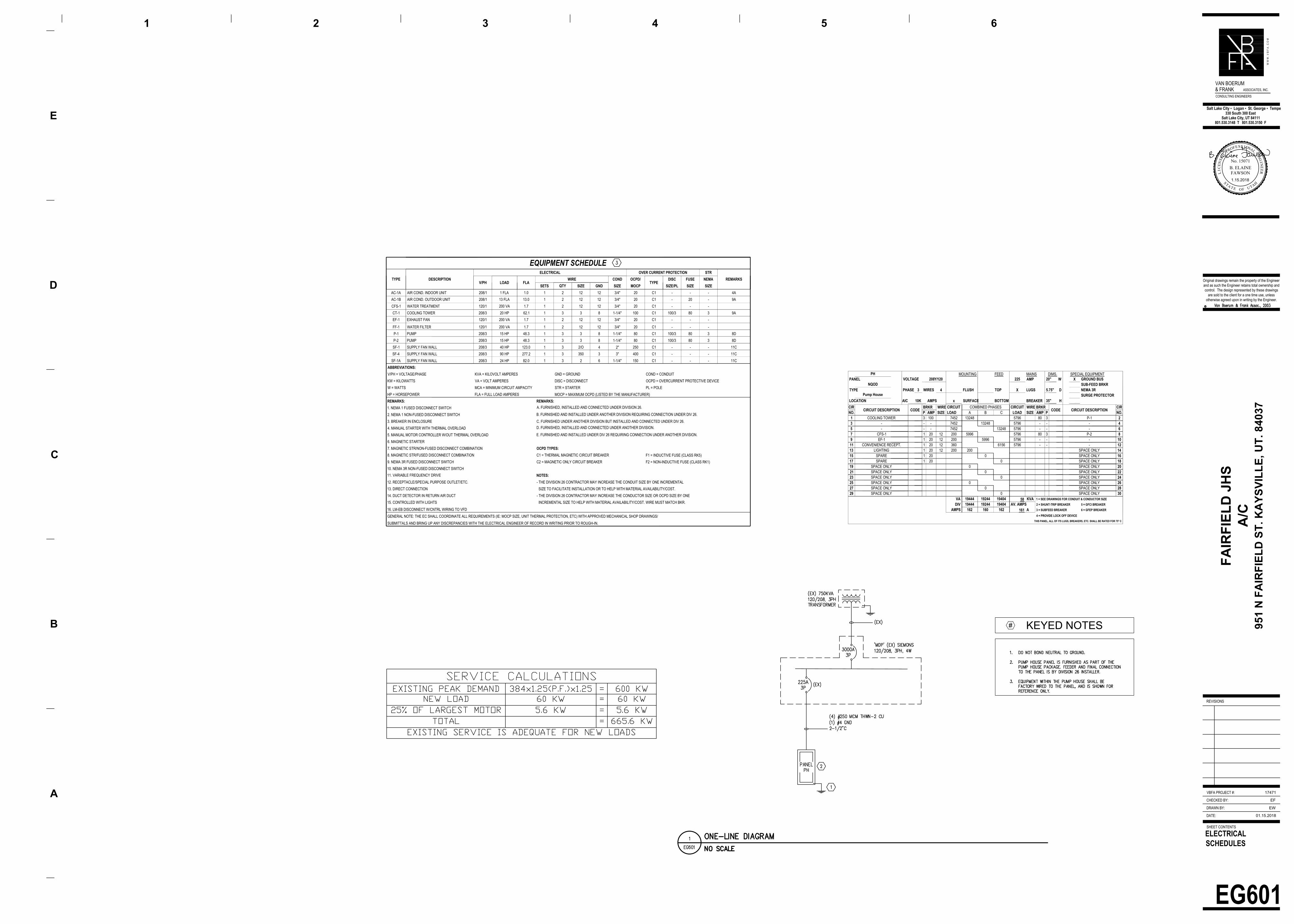
EG601
ELECTRICAL
SCHEDULES
DATE:
DRAWN BY:
CHECKED BY:
SHEET CONTENTS
REVISIONS
Original drawings remain the property of the Engineer
and as such the Engineer retains total ownership and
control. The design represented by these drawings
are sold to the client for a one time use, unless
otherwise agreed upon in writing by the Engineer.
01.15.2018
A
B
D
E
1 2 3 4 5
W W
W
. V
B
F
A
. C
O
M
VBFA PROJECT #: 17471
330 South 300 East
Salt Lake City, UT 84111
801.530.3148 T 801.530.3150 F
Salt Lake City ▪ Logan ▪ St. George ▪ Tempe
VAN BOERUM
& FRANKASSOCIATES, INC.
CONSULTING ENGINEERS
C
6
FA
IR
FIE
LD
JH
S
A/C
951 N
F
AIR
FIE
LD
S
T. K
AY
SV
IL
LE
, U
T. 84037
EW
EF
LIC
ENSE
D P
ROFESS I ONAL ENGIN
EER
No. 15071
S TA T E O F UTAH
B. ELAINEFAWSON1.15.2018
KEYED NOTES
#
PHMOUNTING FEED MAINS DIMS. SPECIAL EQUIPMENT
PANEL VOLTAGE 208Y/120 225 AMP 20" W X GROUND BUS
NQODSUB-FEED BRKR
TYPE PHASE 3 WIRES 4 FLUSH TOP X LUGS 5.75" D NEMA 3R
Pump House
SURGE PROTECTOR
LOCATION AIC 10K AMPS x SURFACE BOTTOM BREAKER 35" H
CIR
CIRCUIT DESCRIPTION CODE
BRKR WIRE CIRCUIT COMBINED PHASES CIRCUIT WIRE BRKR
CODE CIRCUIT DESCRIPTION
CIR
NO. P AMP SIZE LOAD A B C LOAD SIZE AMP P NO.
1 COOLING TOWER 3 100 7452 13248 5796 80 3 P-1 2
3 - - - 7452 13248 5796 - - - 4
5 - - - 7452 13248 5796 - - - 6
7 CFS-1 1 20 12 200 5996 5796 80 3 P-2 8
9 EF-1 1 20 12 200 5996 5796 - - - 10
11 CONVENIENCE RECEPT. 1 20 12 360 6156 5796 - - - 12
13 LIGHTING 1 20 12 200 200 SPACE ONLY 14
15 SPARE 1 20 0 SPACE ONLY 16
17 SPARE 1 20 0 SPACE ONLY 18
19 SPACE ONLY 0 SPACE ONLY 20
21 SPACE ONLY 0 SPACE ONLY 22
23 SPACE ONLY 0 SPACE ONLY 24
25 SPACE ONLY 0 SPACE ONLY 26
27 SPACE ONLY 0 SPACE ONLY 28
29 SPACE ONLY 0 SPACE ONLY 30
VA 19444 19244 19404
58
KVA 1 = SEE DRAWINGS FOR CONDUIT & CONDUCTOR SIZE
DIV 19444 19244 19404 AV. AMPS 2 = SHUNT-TRIP BREAKER 5 = GFCI BREAKER
AMPS 162 160 162
161A 3 = SUBFEED BREAKER 6 = GFEP BREAKER
4 = PROVIDE LOCK OFF DEVICE
THIS PANEL, ALL OF ITS LUGS, BREAKERS, ETC. SHALL BE RATED FOR 75° C
EQUIPMENT SCHEDULE
TYPE DESCRIPTION
ELECTRICAL OVER CURRENT PROTECTION STR
REMARKS
V/PH LOAD FLA
WIRE COND OCPD/
TYPE
DISC FUSE NEMA
SETS QTY SIZE GND SIZE MOCP SIZE/PL SIZE SIZE
AC-1A AIR COND. INDOOR UNIT 208/1 1 FLA 1.0 1 2 12 12 3/4" 20 C1 - - - 4A
AC-1B AIR COND. OUTDOOR UNIT 208/1 13 FLA 13.0 1 2 12 12 3/4" 20 C1 - 20 - 9A
CFS-1 WATER TREATMENT 120/1 200 VA 1.7 1 2 12 12 3/4" 20 C1 - - -
CT-1 COOLING TOWER 208/3 20 HP 62.1 1 3 3 8 1-1/4" 100 C1 100/3 80 3 9A
EF-1 EXHAUST FAN 120/1 200 VA 1.7 1 2 12 12 3/4" 20 C1 - - -
FF-1 WATER FILTER 120/1 200 VA 1.7 1 2 12 12 3/4" 20 C1 - - -
P-1 PUMP 208/3 15 HP 48.3 1 3 3 8 1-1/4" 80 C1 100/3 80 3 8D
P-2 PUMP 208/3 15 HP 48.3 1 3 3 8 1-1/4" 80 C1 100/3 80 3 8D
SF-1 SUPPLY FAN WALL 208/3 40 HP 123.0 1 3 2/O 4 2" 250 C1 - - - 11C
SF-4 SUPPLY FAN WALL 208/3 90 HP 277.2 1 3 350 3 3" 400 C1 - - - 11C
SF-1A SUPPLY FAN WALL 208/3 24 HP 82.0 1 3 2 6 1-1/4" 150 C1 - - - 11C
ABBREVIATIONS:
V/PH = VOLTAGE/PHASE KVA = KILOVOLT AMPERES GND = GROUND COND = CONDUIT
KW = KILOWATTS VA = VOLT AMPERES DISC = DISCONNECT OCPD = OVERCURRENT PROTECTIVE DEVICE
W = WATTS MCA = MINIMUM CIRCUIT AMPACITY STR = STARTER PL = POLE
HP = HORSEPOWER FLA = FULL LOAD AMPERES MOCP = MAXIMUM OCPD (LISTED BY THE MANUFACTURER)
REMARKS: REMARKS:
1. NEMA 1 FUSED DISCONNECT SWITCH
A. FURNISHED, INSTALLED AND CONNECTED UNDER DIVISION 26.
2. NEMA 1 NON-FUSED DISCONNECT SWITCHB. FURNISHED AND INSTALLED UNDER ANOTHER DIVISION REQUIRING CONNECTION UNDER DIV 26.
3. BREAKER IN ENCLOSURE C. FURNISHED UNDER ANOTHER DIVISION BUT INSTALLED AND CONNECTED UNDER DIV 26.
4. MANUAL STARTER WITH THERMAL OVERLOAD
D. FURNISHED, INSTALLED AND CONNECTED UNDER ANOTHER DIVISION.
5. MANUAL MOTOR CONTROLLER W/OUT THERMAL OVERLOADE. FURNISHED AND INSTALLED UNDER DIV 26 REQUIRING CONNECTION UNDER ANOTHER DIVISION.
6. MAGNETIC STARTER
7. MAGNETIC STR/NON-FUSED DISCONNECT COMBINATION OCPD TYPES:
8. MAGNETIC STR/FUSED DISCONNECT COMBINATION C1 = THERMAL MAGNETIC CIRCUIT BREAKER F1 = INDUCTIVE FUSE (CLASS RK5)
9. NEMA 3R FUSED DISCONNECT SWITCH C2 = MAGNETIC ONLY CIRCUIT BREAKER F2 = NON-INDUCTIVE FUSE (CLASS RK1)
10. NEMA 3R NON-FUSED DISCONNECT SWITCH
11. VARIABLE FREQUENCY DRIVENOTES:
12. RECEPTACLE/SPECIAL PURPOSE OUTLET/ETC. - THE DIVISION 26 CONTRACTOR MAY INCREASE THE CONDUIT SIZE BY ONE INCREMENTAL
13. DIRECT CONNECTION SIZE TO FACILITATE INSTALLATION OR TO HELP WITH MATERIAL AVAILABILITY/COST.
14. DUCT DETECTOR IN RETURN AIR DUCT - THE DIVISION 26 CONTRACTOR MAY INCREASE THE CONDUCTOR SIZE OR OCPD SIZE BY ONE
15. CONTROLLED WITH LIGHTS INCREMENTAL SIZE TO HELP WITH MATERIAL AVAILABILITY/COST. WIRE MUST MATCH BKR.
16. LM-EB DISCONNECT W/CNTRL WIRING TO VFD
GENERAL NOTE: THE EC SHALL COORDINATE ALL REQUIREMENTS (IE: MOCP SIZE, UNIT THERMAL PROTECTION, ETC) WITH APPROVED MECHANICAL SHOP DRAWINGS/
SUBMITTALS AND BRING UP ANY DISCREPANCIES WITH THE ELECTRICAL ENGINEER OF RECORD IN WRITING PRIOR TO ROUGH-IN.
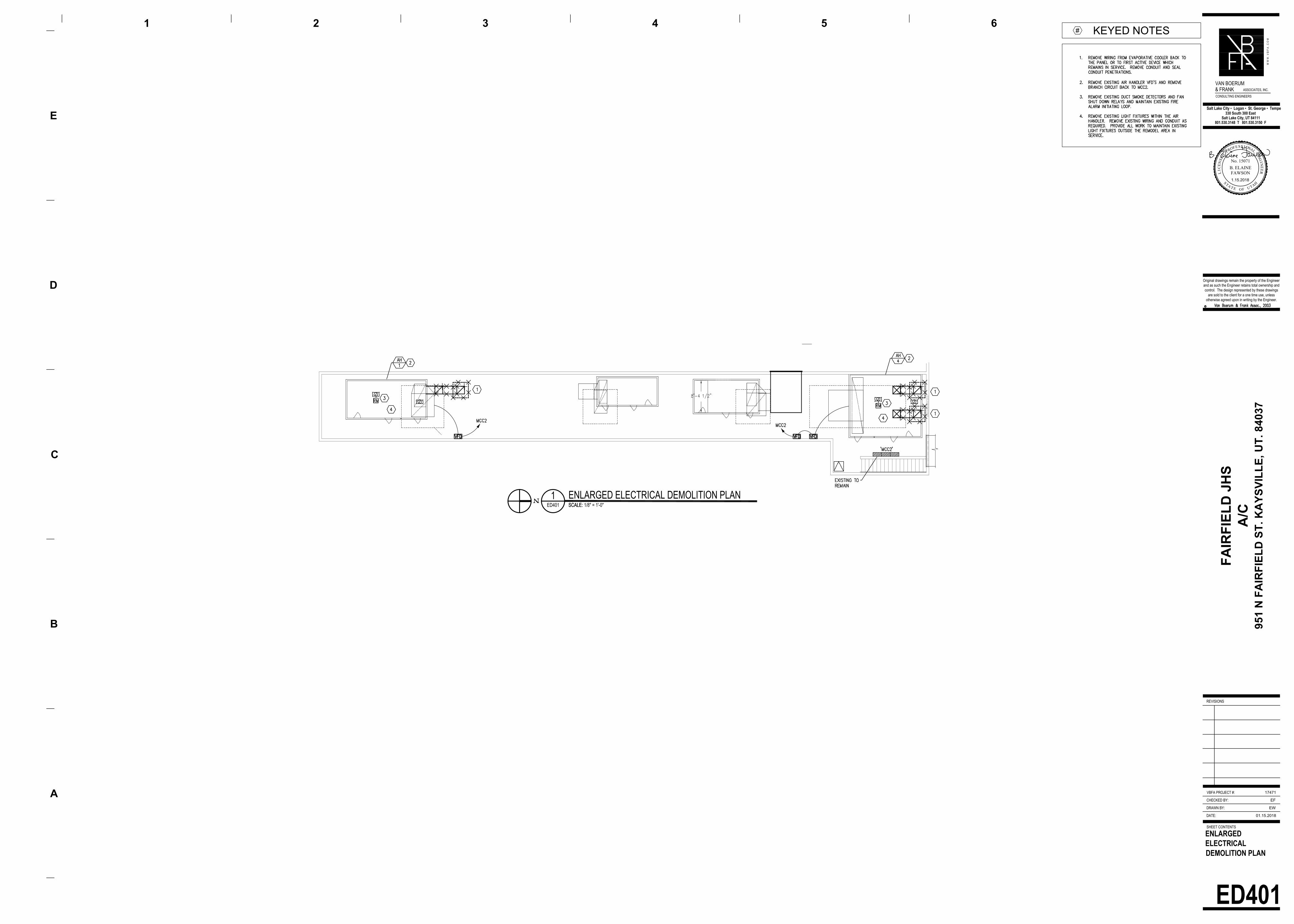
DATE:
DRAWN BY:
CHECKED BY:
SHEET CONTENTS
REVISIONS
Original drawings remain the property of the Engineer
and as such the Engineer retains total ownership and
control. The design represented by these drawings
are sold to the client for a one time use, unless
otherwise agreed upon in writing by the Engineer.
01.15.2018
A
B
D
E
1 2 3 4 5
W W
W
. V
B
F
A
. C
O
M
VBFA PROJECT #: 17471
330 South 300 East
Salt Lake City, UT 84111
801.530.3148 T 801.530.3150 F
Salt Lake City ▪ Logan ▪ St. George ▪ Tempe
VAN BOERUM
& FRANKASSOCIATES, INC.
CONSULTING ENGINEERS
C
6
FA
IR
FIE
LD
JH
S
A/C
951 N
F
AIR
FIE
LD
S
T. K
AY
SV
IL
LE
, U
T. 84037
EW
EF
LIC
ENSE
D P
ROFESS I ONAL ENGIN
EER
No. 15071
S TAT E O F U TAH
B. ELAINEFAWSON1.15.2018
KEYED NOTES
#
ED401 SCALE: 1/8" = 1'-0"
1ENLARGED ELECTRICAL DEMOLITION PLAN
SCALE:
ED401
ENLARGED
ELECTRICAL
DEMOLITION PLAN
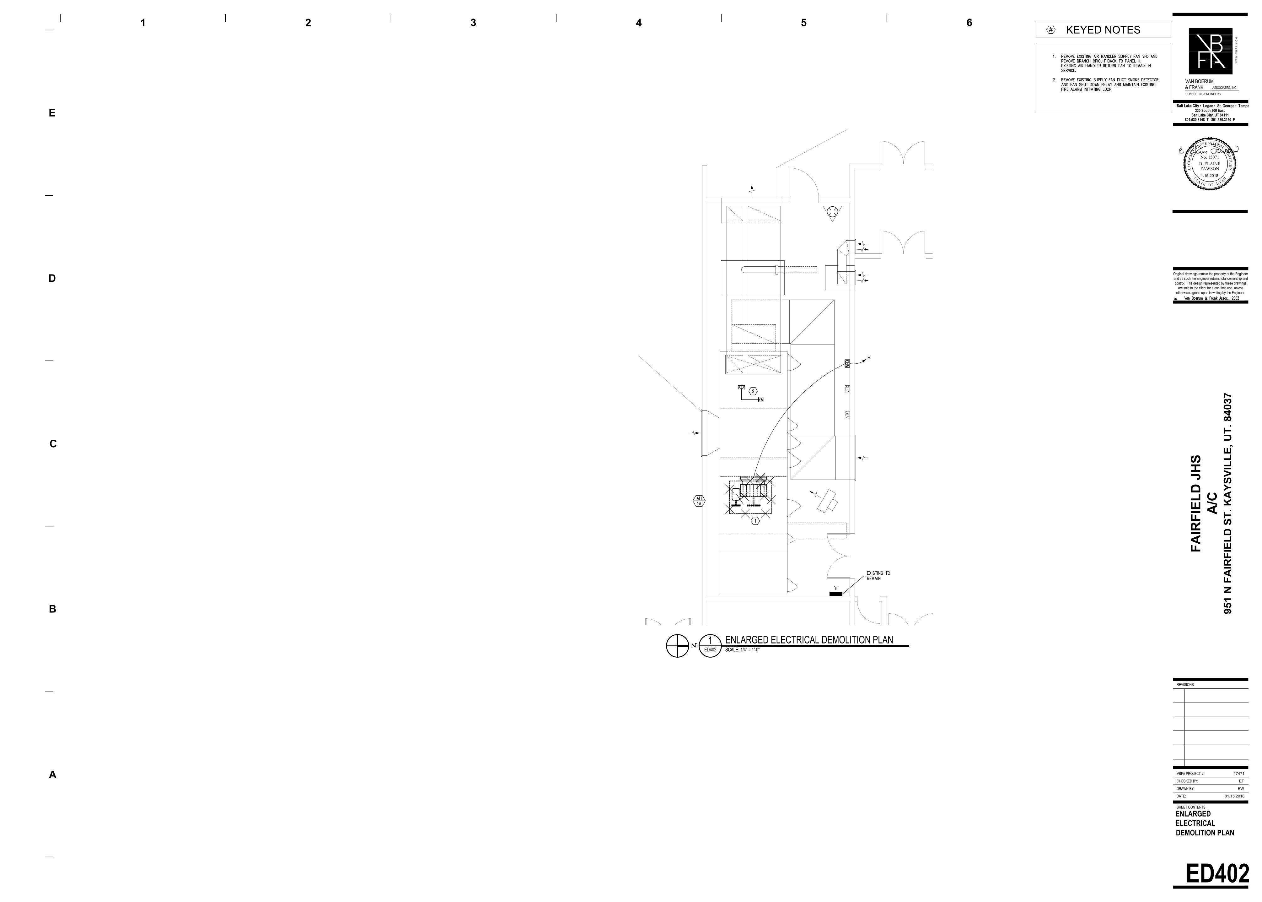
DATE:
DRAWN BY:
CHECKED BY:
SHEET CONTENTS
REVISIONS
Original drawings remain the property of the Engineer
and as such the Engineer retains total ownership and
control. The design represented by these drawings
are sold to the client for a one time use, unless
otherwise agreed upon in writing by the Engineer.
01.15.2018
A
B
D
E
1 2 3 4 5
W W
W
. V
B
F
A
. C
O
M
VBFA PROJECT #: 17471
330 South 300 East
Salt Lake City, UT 84111
801.530.3148 T 801.530.3150 F
Salt Lake City ▪ Logan ▪ St. George ▪ Tempe
VAN BOERUM
& FRANKASSOCIATES, INC.
CONSULTING ENGINEERS
C
6
FA
IR
FIE
LD
JH
S
A/C
951 N
F
AIR
FIE
LD
S
T. K
AY
SV
IL
LE
, U
T. 84037
EW
EF
LIC
ENSE
D P
ROFESS I ONAL ENGIN
EER
No. 15071
S TA T E O F U TAH
B. ELAINEFAWSON1.15.2018
KEYED NOTES
#
ED402 SCALE: 1/4" = 1'-0"
1ENLARGED ELECTRICAL DEMOLITION PLAN
SCALE:
ED402
ENLARGED
ELECTRICAL
DEMOLITION PLAN

EP101
OVERALL
ELECTRICAL PLAN
EP101 SCALE: 1" = 20'-0"
1OVERALL ELECTRICAL PLAN
SCALE:
DATE:
DRAWN BY:
CHECKED BY:
SHEET CONTENTS
REVISIONS
Original drawings remain the property of the Engineer
and as such the Engineer retains total ownership and
control. The design represented by these drawings
are sold to the client for a one time use, unless
otherwise agreed upon in writing by the Engineer.
01.15.2018
A
B
D
E
1 2 3 4 5
W W
W
. V
B
F
A
. C
O
M
VBFA PROJECT #: 17471
330 South 300 East
Salt Lake City, UT 84111
801.530.3148 T 801.530.3150 F
Salt Lake City ▪ Logan ▪ St. George ▪ Tempe
VAN BOERUM
& FRANKASSOCIATES, INC.
CONSULTING ENGINEERS
C
6
FA
IR
FIE
LD
JH
S
A/C
951 N
F
AIR
FIE
LD
S
T. K
AY
SV
IL
LE
, U
T. 84037
EW
EF
LIC
ENSE
D P
ROFESS I ONAL ENGIN
EER
No. 15071
S TA T E O F U TAH
B. ELAINEFAWSON1.15.2018
KEYED NOTES
#

1ELECTRICAL PLAN AREA C
SCALE: EP113 SCALE: 1/8" = 1'-0"
KEY PLAN
KEYED NOTES
#
DATE:
DRAWN BY:
CHECKED BY:
SHEET CONTENTS
REVISIONS
Original drawings remain the property of the Engineer
and as such the Engineer retains total ownership and
control. The design represented by these drawings
are sold to the client for a one time use, unless
otherwise agreed upon in writing by the Engineer.
01.15.2018
A
B
D
E
1 2 3 4 5
W W
W
. V
B
F
A
. C
O
M
VBFA PROJECT #: 17471
330 South 300 East
Salt Lake City, UT 84111
801.530.3148 T 801.530.3150 F
Salt Lake City ▪ Logan ▪ St. George ▪ Tempe
VAN BOERUM
& FRANKASSOCIATES, INC.
CONSULTING ENGINEERS
C
6
FA
IR
FIE
LD
JH
S
A/C
951 N
F
AIR
FIE
LD
S
T. K
AY
SV
IL
LE
, U
T. 84037
EW
EF
LIC
ENSE
D P
ROFESS I ONAL ENGIN
EER
No. 15071
S TA T E O F UTAH
B. ELAINEFAWSON1.15.2018
EP113
ELECTRICAL PLAN
AREA C
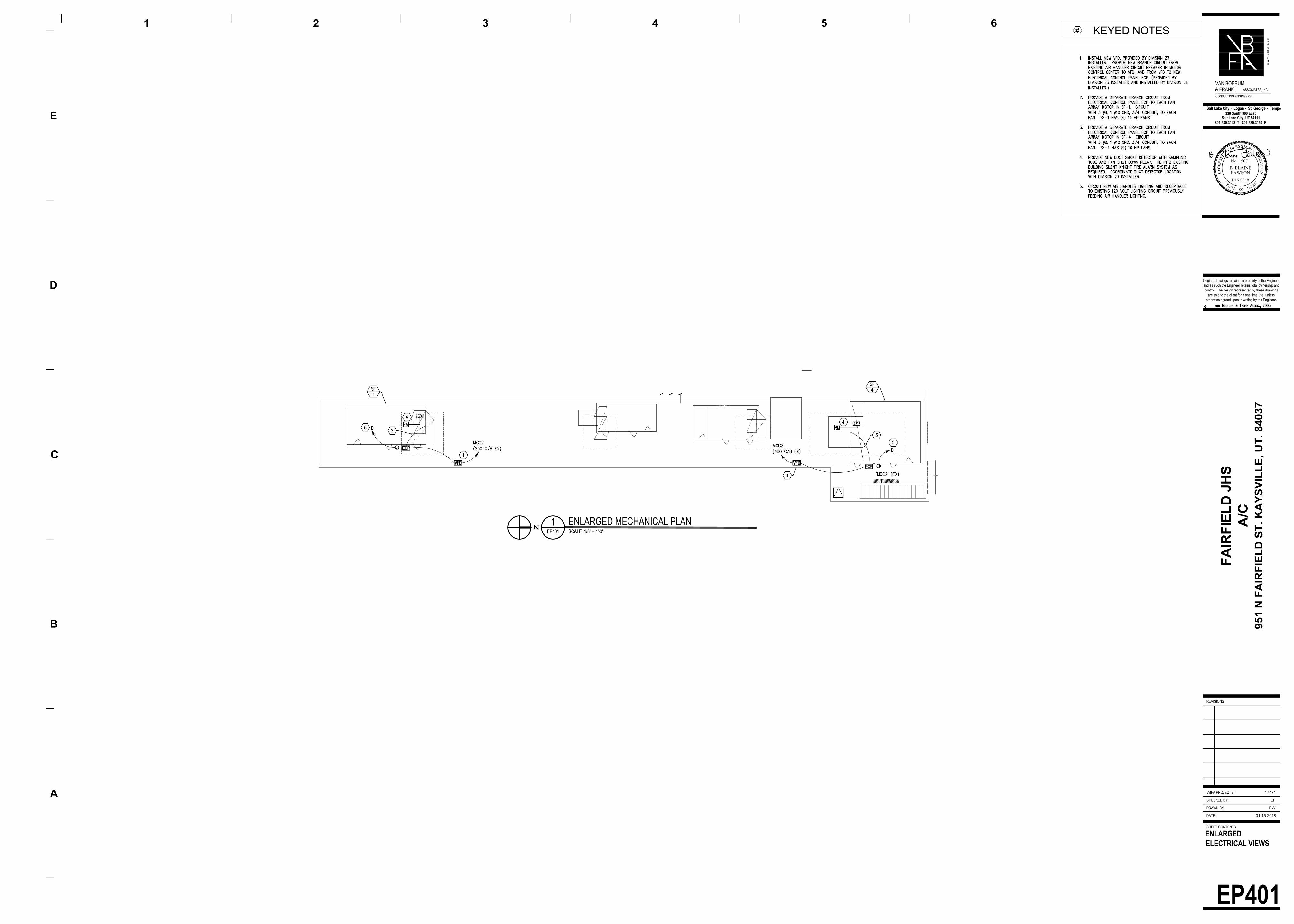
DATE:
DRAWN BY:
CHECKED BY:
SHEET CONTENTS
REVISIONS
Original drawings remain the property of the Engineer
and as such the Engineer retains total ownership and
control. The design represented by these drawings
are sold to the client for a one time use, unless
otherwise agreed upon in writing by the Engineer.
01.15.2018
A
B
D
E
1 2 3 4 5
W W
W
. V
B
F
A
. C
O
M
VBFA PROJECT #: 17471
330 South 300 East
Salt Lake City, UT 84111
801.530.3148 T 801.530.3150 F
Salt Lake City ▪ Logan ▪ St. George ▪ Tempe
VAN BOERUM
& FRANKASSOCIATES, INC.
CONSULTING ENGINEERS
C
6
FA
IR
FIE
LD
JH
S
A/C
951 N
F
AIR
FIE
LD
S
T. K
AY
SV
IL
LE
, U
T. 84037
EW
EF
LIC
ENSE
D P
ROFESS I ONAL ENGIN
EER
No. 15071
S TA T E O F U TAH
B. ELAINEFAWSON1.15.2018
KEYED NOTES
#
”
”
EP401 SCALE: 1/8" = 1'-0"
1ENLARGED MECHANICAL PLAN
SCALE:
EP401
ENLARGED
ELECTRICAL VIEWS

DATE:
DRAWN BY:
CHECKED BY:
SHEET CONTENTS
REVISIONS
Original drawings remain the property of the Engineer
and as such the Engineer retains total ownership and
control. The design represented by these drawings
are sold to the client for a one time use, unless
otherwise agreed upon in writing by the Engineer.
01.15.2018
A
B
D
E
1 2 3 4 5
W W
W
. V
B
F
A
. C
O
M
VBFA PROJECT #: 17471
330 South 300 East
Salt Lake City, UT 84111
801.530.3148 T 801.530.3150 F
Salt Lake City ▪ Logan ▪ St. George ▪ Tempe
VAN BOERUM
& FRANKASSOCIATES, INC.
CONSULTING ENGINEERS
C
6
FA
IR
FIE
LD
JH
S
A/C
951 N
F
AIR
FIE
LD
S
T. K
AY
SV
IL
LE
, U
T. 84037
EW
EF
LIC
ENSE
D P
ROFESS I ONAL ENGIN
EER
No. 15071
S TA T E O F U TAH
B. ELAINEFAWSON1.15.2018
KEYED NOTES
#
”
EP402 SCALE: 1/4" = 1'-0"
1ENLARGED MECHANICAL PLAN
SCALE: EP402 SCALE: 1/4" = 1'-0"
2ENLARGED MECHANICAL PLAN PUMP HOUSE
SCALE:
EP402
ENLARGED
ELECTRICAL VIEWS