Embed Size (px)
Citation preview

Fair Contracts for Underground Constructions – the Austrian Practice
Prof. Dr. Robert Galler Subsurface Engineering &
ZaB – Underground Research Center Montanuniversitaet Leoben, Austria
R. Galler

R. Galler
The first 2 main rules are
• the ground belongs to the client and is his risk
• a unit price contract is used
Please keep these 2 principles in mind for the following explanations!
Introduction
R. Galler
Contractual regulations in tunneling have to
be different from other sectors of the
construction industry
because
the construction material, the ground, is
not known exactly until we do the
underground construction!
Contracting practices

R. Galler
General risk sharing for underground constructions:
• The ground belongs to the client and is his risk
• Means and methods for unchanged ground conditions (compared to the prognosis) are the contractor’s risk
Risk sharing
R. Galler
History first issue: 1975
Revisions: 1983, 1994, 2001
2001: Part 1 – conventional tunnelling 2005: Part 2 – mechanized tunnelling
ÖNORM B2203: Underground works
Standard
R. Galler
1) Rules of Procedure 2) Terms of Contract
• Part 1: for the implementation of underground
works using conventional tunnelling.
• Does not apply to pipe jacking and tunnels constructed by cut & cover or open pit methods!
Scope of ÖNORM B2203
R. Galler
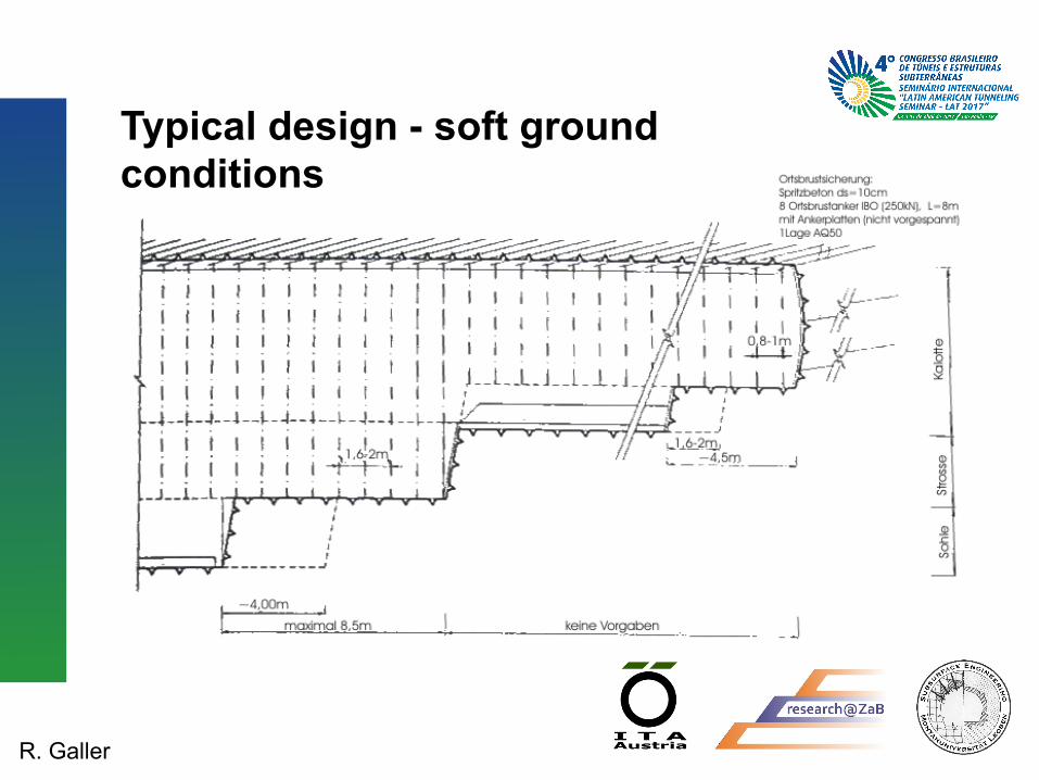
Typical design - soft ground conditions

R. Galler
Typical design - soft ground conditions

R. Galler
The classification system considers two major factors, which are decisive for advance rate and cost:
• Ground properties and ground behaviour during excavation
• Amount and type of supporting measures on the advance rate
Classification system

R. Galler
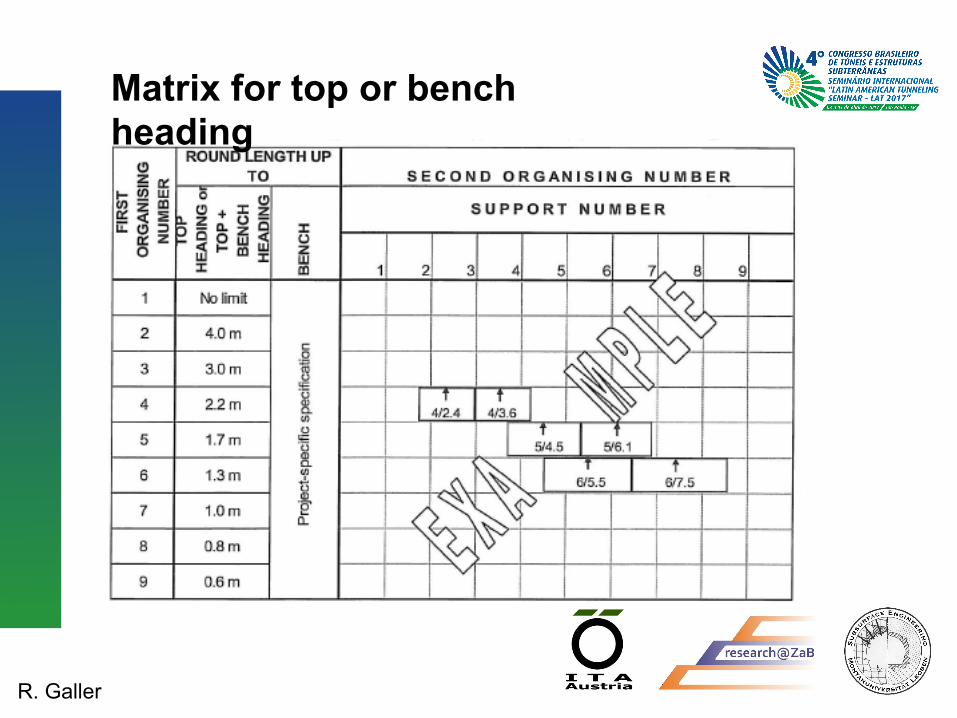
The matrix shall comply with the following principles:
• First Organising Number: Subdivision of Top, Bench or Top-plus-Bench headings according to the round-length range
• Second Organising Number: Support and supplementary measures in the top, bench or top-plus-bench headings shall be rated with the Support Factor.
Classification system
R. Galler
Matrix for top or bench heading

R. Galler
The Matrix is defined and filled as follows: − round length (1. Organising Number) − support factor (2. Organising Number)
• rating factors for each support element (indirectly reflecting the time necessary for installation)
• rating area − result: single point => would lead to an infinite
number of such excavation points
Tunnelling classes (better: excavation and support- classes)

R. Galler
The Matrix is defined and filled as follows:
− support factors are limited by a tolerance of ± 0,35 to ± 2,1, depending on the round length defining areas => excavation classes
− for each class the bidder supplies a unit price for excavation and a guaranteed advance rate (m/day)
− topheading, bench and invert separately
Tunnelling classes (better: excavation and support- classes)
R. Galler
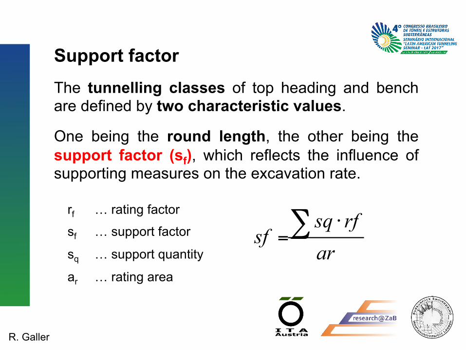
The tunnelling classes of top heading and bench are defined by two characteristic values.
One being the round length, the other being the support factor (sf), which reflects the influence of supporting measures on the excavation rate.
arrfsq
sf ∑ ⋅=
rf … rating factor
sf … support factor
sq … support quantity
ar … rating area
Support factor

R. Galler
Rating Factorper quantity unit
quantity unit
Swellex or equal 0,8 mSN Rockbolts 1,1 mSelfdrilling Rockbolts 1,7 mGrouted Tube Anchors 2,0 mRockbolts tensioned 2,5 mNumber of Anchors per Roundlength 8,0 PCSPlacement of Anchorplates without Tensioning 1,7 PCSPlacement of Anchorplates with Tensioning 5,0 PCSdriven Spiles 0,5 mungrouted Spiles 0,6 mgrouted Spiles 0,9 mSelfdrilling Spiles 1,3 mGrouted Tube Spiles 1,6 m
Grouting more than 10 kg per m Anchor, Spile, Footpile 0,1 kgexterior (rock) side with Arch 1,0 m²interior (excavation) side with Arch 1,5 m²exterior (rock) side without Arch 2,0 m²Temporary invert ot Topheading 0,8 m²Additional Reinforcement, Face Mesh Reinforcement 2,0 m²
Arch and Dispatcher 2,0 mTopheading and Bench 20,0 m³temp. Invert of Topheading, Elephant Footing 12,0 m³Face 14,0 m³Filling of gaps and Overexcavation 14,0 m³withoutStress Controller 3,5 mwith Stress Controller 5,0 m
Forepolingboards 5,5 m²Footpiles ∅ ≤ 38mm 4,5 mFootpiles ∅ ≥ 38mm 5,0 m
Sequences 22,0 PCSExcavation Elephantfooting 50,0 mDemolition temporary invert of Topheading whilst Benchexcavation 50,0 m
Steel mesh
Shotcrete
Deformationsslots
Footpiles
Support and additional measures
Anchors andRockbolts
Faceanchors
Spiles
Rating factors

R. Galler
Round LengthTopheading
Maximum scope for second ordinal number
(Support Factor) Topheading
Round lengthbench maximum
Maximum scope for second ordinal number
(Support Factor)Bench
no limit +/- 0,354,0 m +/- 0,353,0 m +/- 0,452,2 m +/- 0,601,7 m +/- 0,801,3 m +/- 1,001,0 m +/- 1,300,8 m +/- 1,600,6 m +/- 2,10
2,0 m +/- 1,20
1,0 m +/- 2,10
no limit +/- 0,45
3,0 m +/- 0,70
Limits of the Second Organising Number

R. Galler
Excavation Class Matrix - example

R. Galler
Example Topheading of a typical two lane highway tunnel

R. Galler
30 Spiles, a‘ 2m
Facesealing 50% with 4cm Shotcrete
10 Rockbolts, a‘ 5,5m
25cm Shotcrete with 2 Layers of Wire Mesh 1 Lattice Girder

R. Galler
further informations: Round length 1,3m
10m2
50m2
55m2
23m
R. Galler
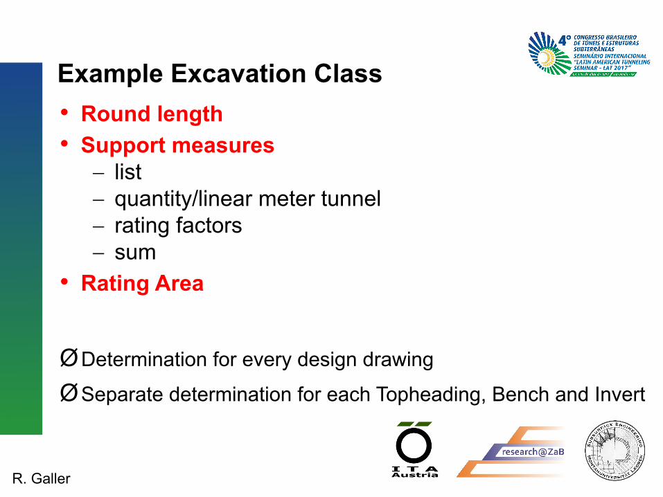
• Round length • Support measures
− list − quantity/linear meter tunnel − rating factors − sum
• Rating Area
Ø Determination for every design drawing
Ø Separate determination for each Topheading, Bench and Invert
Example Excavation Class
R. Galler
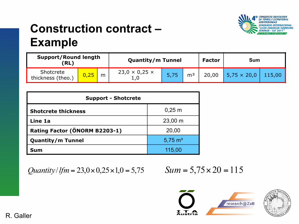
Construction contract – Example
Support/Round length (RL) Quantity/m Tunnel Factor Sum
Shotcrete thickness (theo.) 0,25 m 23,0 × 0,25 ×
1,0 5,75 m³ 20,00 5,75 × 20,0 115,00
Support - Shotcrete
Shotcrete thickness 0,25 m
Line 1a 23,00 m
Rating Factor (ÖNORM B2203-1) 20,00
Quantity/m Tunnel 5,75 m³
Sum 115,00
75,50,125,00,23/ =××=lfmQuantity 1152075,5 =×=Sum

R. Galler
Construction contract – Example
Support - Rockbolts
Rockbolts 10 Pieces
Bolt length 5,50 m
Round length 1,30 m
Rating Factor (ÖNORM B2203-1) 0,80
Quantity/m Tunnel 42,31 m
Sum 33,85
Support/Round length (RL) Quantity/m Tunnel Factor Sum
Rockbolts Swellex
(RL) 10,00 Pieces (10 × 5,5)/1,3 42,31 m 0,80 42,31 ×0,8 33,85
( ) 31,423,15,510/ =
×=lfmQuantity 85,338,031,42 =×=Sum
R. Galler
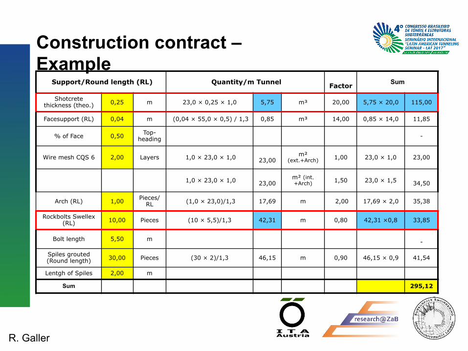
Support/Round length (RL) Quantity/m Tunnel Factor Sum
Shotcrete thickness (theo.) 0,25 m 23,0 × 0,25 × 1,0 5,75 m³ 20,00 5,75 × 20,0 115,00
Facesupport (RL) 0,04 m (0,04 × 55,0 × 0,5) / 1,3 0,85 m³ 14,00 0,85 × 14,0 11,85
% of Face 0,50 Top-heading -
Wire mesh CQS 6 2,00 Layers 1,0 × 23,0 × 1,0 23,00
m² (ext.+Arch) 1,00 23,0 × 1,0 23,00
1,0 × 23,0 × 1,0 23,00
m² (int.+Arch) 1,50 23,0 × 1,5
34,50
Arch (RL) 1,00 Pieces/RL (1,0 × 23,0)/1,3 17,69 m 2,00 17,69 × 2,0 35,38
Rockbolts Swellex (RL) 10,00 Pieces (10 × 5,5)/1,3 42,31 m 0,80 42,31 ×0,8 33,85
Bolt length 5,50 m -
Spiles grouted (Round length) 30,00 Pieces (30 × 2)/1,3 46,15 m 0,90 46,15 × 0,9 41,54
Lentgh of Spiles 2,00 m
Sum 295,12
Construction contract – Example

R. Galler
Calculation Excavation Class Round length 1,30 1. Ordinal Number 6,00
Line 1a 23,00
Topheading Area 55,00 2. Ordinal Number 295,15 / 55,00 5,37
Support 295,12
Construction contract – Example

R. Galler
Example Excavation Class Matrix
1 2 3 4 5 6 7 8 9
1 no limit
2 4,0 m
3 3,0 m
4 2,2 m
5 1,7 m
6 1,3 m
7 1,0 m
8 0,8 m
9 0,6 m
is to
be
dete
rmine
d fo
r eac
h pr
oject
FIRS
T OR
DINA
L NU
MBE
R
Round length maximumSECOND ORDINAL NUMBER
TOPH
EADI
NG
or TOPH
EADI
NG +
BENC
H
BENC
HSUPPORT FACTOR
6/5,37
1,0 1,0
Round LengthTopheading
Maximum scope for second ordinal number
(Support Factor) Topheading
Round lengthbench maximum
Maximum scope for second ordinal number
(Support Factor)Bench
no limit +/- 0,354,0 m +/- 0,353,0 m +/- 0,452,2 m +/- 0,601,7 m +/- 0,801,3 m +/- 1,001,0 m +/- 1,300,8 m +/- 1,600,6 m +/- 2,10
2,0 m +/- 1,20
1,0 m +/- 2,10
no limit +/- 0,45
3,0 m +/- 0,70

R. Galler
Example for Tunnelling – Class extrapolation

R. Galler
• Having available rock mass types the excavation and support classes will be derived.
• The distribution of these classes along the tunnel alignment is based on the geotechnical data from the site investigations.
• For each class the excavation time can be calculated.
• This gives an excavation velocity in meter per month and shall be a contractual component.
• The summation of the excavation time of all tunnelling classes gives the total excavation time for the tunnel.
Construction time TIME DEPENDENT COST

R. Galler
Construction contract • Generally the time required for excavation and support
as well as the additional time required because of delays such as water hindrances is kept variable.
• In his offer the contractor has to indicate advance rates for each class and rates for reductions due to hindrances, all of which he has to guarantee.
• The adjusted construction time is the basis for the compensation of all time dependent costs.

R. Galler
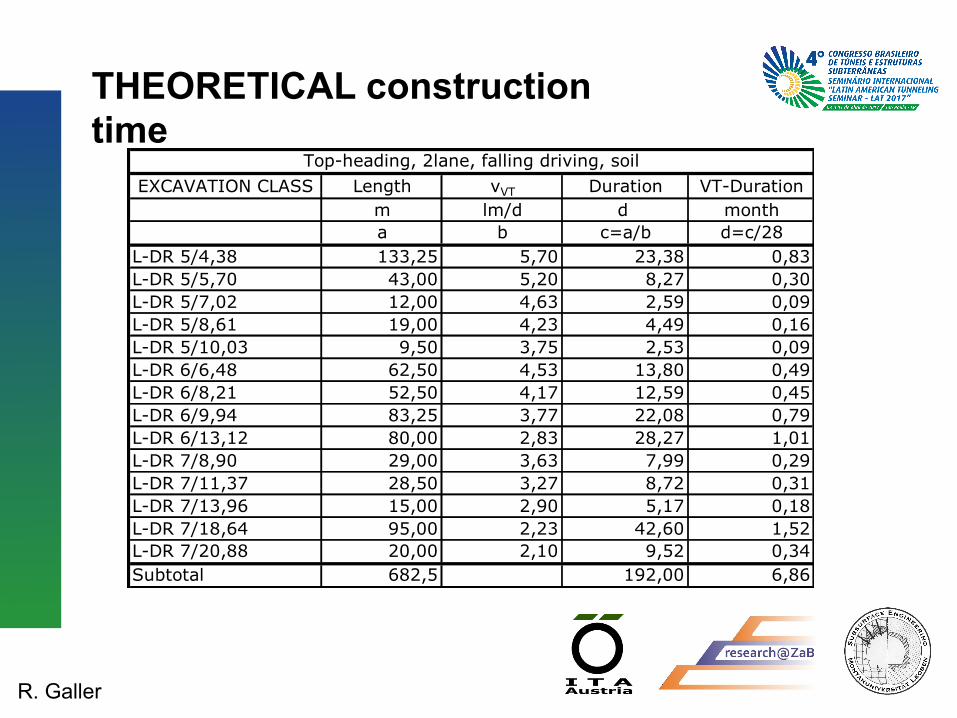
THEORETICAL construction time
• Each individual excavation class requires a certain amount of time for excavation and installation of support measures.
• The estimated time required for the relevant works leads to the assessment of progress rates for different classes.
• The application of the assessed progress rates for the predicted rock class distribution yields a theoretical construction time for the tunnelling works before the commencement of tunnelling works.
R. Galler
THEORETICAL construction time
EXCAVATION CLASS Length vVT Duration VT-Durationm lm/d d montha b c=a/b d=c/28
L-DR 5/4,38 133,25 5,70 23,38 0,83L-DR 5/5,70 43,00 5,20 8,27 0,30L-DR 5/7,02 12,00 4,63 2,59 0,09L-DR 5/8,61 19,00 4,23 4,49 0,16L-DR 5/10,03 9,50 3,75 2,53 0,09L-DR 6/6,48 62,50 4,53 13,80 0,49L-DR 6/8,21 52,50 4,17 12,59 0,45L-DR 6/9,94 83,25 3,77 22,08 0,79L-DR 6/13,12 80,00 2,83 28,27 1,01L-DR 7/8,90 29,00 3,63 7,99 0,29L-DR 7/11,37 28,50 3,27 8,72 0,31L-DR 7/13,96 15,00 2,90 5,17 0,18L-DR 7/18,64 95,00 2,23 42,60 1,52L-DR 7/20,88 20,00 2,10 9,52 0,34Subtotal 682,5 192,00 6,86
Top-heading, 2lane, falling driving, soil

R. Galler
ACTUAL construction time • With the documentat ion of the actual rock
classification the initial theoretical construction time is adjusted
• and any difference will be used for re-definition of the target dates and for reimbursement of corresponding payment items.
• Continuous monitoring of the progress with respect to the theoretical construction time allows to allocate the cause of delays.

R. Galler
Time dependent costs • The encountered class distribution will be different
from the assumed distribution.
• That means the total excavation time may be different compared to the time based on the geological prognosis as proposed in the tender drawings.
• The advantage of this model is that both the contractor and the client shear the risk of additional costs which result from the difference between the geological prognosis and the encountered geological conditions.

R. Galler
CONTRACTUAL construction time • Due to the actual classes the actual construction time
may be extended and reimbursement of corresponding payment items will be adjusted.
• In the used model where payment is time dependent both the contractor and the client shear the risk of the actual underground conditions which may differ from the predicted geological assessments.
• Recalculation of the actual construction time is based on the excavation progress rates (excavation velocity) which was specified by the contractor as a contractual component.

R. Galler
Excavation Period - Example
TenderVKL 1 VKL 2 VKL 3 Summe
Tender (prognosis) 100m 100m 100m 300mBidder: Advance Rate 10 m/d 5 m/d 1 m/dExcavation Period 10 days 20 days 100 days 130 days
time dependent costs, total 1.300.000 € for 130 days = 10.000 €/d
AccountingVKL 1 VKL 2 VKL 3 Summe
actual length (Ist) 140 m 80 m 80 m 300mBidder: Advance Rate 10 m/d 5 m/d 1 m/dExcavation Period 14 days 16 days 80 days 110 days
time dependent costs, total 10.000 €/d for 110 days = 1.100.000 €

R. Galler
Excavation Periods to be distinguished • Excavation Period
− needed time units for excavation plus time when no driving takes place and when other works take place (interruption)
• Predicted Excavation Period − predicted distribution Excavation Classes − contractual appointed Advance Rate − plus expected layoffs and interruptions
• Contractual Excavation Period − actual distribution of Excavation Classes − contractual appointed Advance Rate − plus accepted layoffs and interruptions

R. Galler
Payment of additional construction time
• The additional time dependent costs have to be paid by the client only if the reason for the longer construction time belongs to the owner’s risks.
• The inability of the contractor to perform under prescribed contractual conditions is no reason for additional payment.

R. Galler
• According to the geological conditions the amount of water inflow will be specified in classes of litre per second by the client. Also a minimum and maximum value in percentage of reduction in excavation progress will be specified.
• The contractor has to consider a value which is in the given range of minimum and maximum percentage for his time calculations.
• The time (in days) during the water inflow is expected will be specified based on the geological data for each range of water inflow.
• An amount of water inflow less than 0.5 litres per second shall be included in the unit price and will not obstruct the progress of the excavation work.
Inflow of water
R. Galler
Hindrances due to water
• Hindrances due to wateringress is compensated by extra excavation time, by using reduction factors.
• Depending on the amount of waterinflow and water hindrance classes the bidder has to state factors depending on the inclination of the tunnel.

R. Galler
Consideration of Groundwater The varying impact of water on the ground as well as the water-ingress locations within the excavation profile shall be described on a project specific basis and assigned to the water complication classes as shown in the following table:

R. Galler
ADDITIONAL excavation duration due to water hindrances
Water quantity min. max. add. min. max. add. min. max. add. min. max. add. TOTALl/s days % % % days days % % % days days % % % days days % % % days days
a1 b1 c1 d1 a1/(1-d1)-
a2 b2 c2 d2 a2/(1-d2)-
a3 b3 c3 d3 a3/(1-d3)-
a4 b4 c4 d4 a4/(1-d4)-
e1+e2+e3
Lf1 0,5 to 2 2 0% 10% 4% 0,08 14 5% 15% 7% 1,05 38 10% 20% 12% 5,18 26 15% 25% 17% 5,33 11,60
Lf2beyond2below 5
2 10% 20% 12% 0,27 2 15% 25% 16% 0,38 0,70
Lf3beyond 5below 10
0,00
Lf4beyond 10below 20
0,00
Lf5beyond 20below 40
0,00
Lf6 beyond 40 10 40% 50% 41% 6,95 7,00
19,30
Hindrance-class
favourable medium unfavourable1 2 3
very unfavourable4
Water Hindrances

R. Galler
Unit price contract
Principle:
As a rule and to be fair NATM should be executed on the basis of unit price contracts!!!

R. Galler
Suggested Organisation
CLIENT Project Management
Site Supervision
CONTRACTOR
Independent Controlling
Health and Safety
DESIGNER
Geological documentation
Geotechnical Engineer
Geotechnical Monitoring
Tunnelling Expert

R. Galler
Thanks for your attention!