Embed Size (px)
Citation preview
Original Article
LatinAmericanJournalofSolidsandStructures,2018,15 1 ,e05
FailureAnalysisofPolypropyleneFiberReinforcedConcreteTwo‐WaySlabsSubjectedtoStaticandImpactLoadInducedby
FreeFallingMass
AbstractTheimpactresistanceofconcreteisconsideredaspoorduetoarelativelyenergydissipatingcharacteristicsandtensilestrength.Therefore,thispaperinvestigatesthefeasibilityofusingpolypropylenefibers PF toenhancepunchingshearcapacityofreinforcedconcrete RC two‐wayslabssubjectedtodrop‐weightimpacts.Theevaluatedparametersincludedtwoslabthickness 70mmand90mm ,fivedifferentPFper‐centages 0%,0.3%,0.6%,0.9%,and1.2% ,andtwoimpactloadheight 1.2mand2.4m .Thetestedslabsdividedintothreegroups:notsubjectedtoimpactload,subjectedtoim‐pactloadataheightof1.2m,andsubjectedtoimpactloadataheightof2.4m,resultinginatotalof25slabs.Thebehaviorofeachtwo‐wayRCslabwasevaluatedintermsofthecrackpatterns,ultimatepunchingshearcapacity.Thepresentex‐perimental data can be used for further assessment of theperformance of PF reinforced concretes two‐way slabs aswellasprovidingawell‐documenteddatasetrelatedtotheimpact‐resistant applications which is presently limitedwithintheliterature.TheresultsshowedthataddingthePFatadosageof0.3to1.2%byvolumeofconcreteandincreas‐ingtheslabthicknessfrom70mmto90mmleadstoconsid‐erableenhancementintheoverallstructuralbehavioroftheslabsandtheirresistancetoimpactloading.Interestingly,thedegradation in the ultimate punching capacity of the slabssubjectedtoimpactloadataheightof1.2and2.4mis30.5%and34.6%,respectively.Finally,anempiricalmodelwaspro‐posedforpredictingthepunchingshearcapacityofRCtwo‐wayslabsbasedonreliableexperimentalresultsavailableinliterature
KeywordsPost Behavior; Impact Resistance; Polypropylene Fiber;ReinforcedConcrete;Two‐WaySlabs.
1INTRODUCTION
Theresponseofreinforcedconcrete RC elementssubjectedtoimpactloadisahottopicinthepreviouspublishedresearchworkandstillneedsmoreelaborationinordertounderstandtheircom‐plexbehavior.ThishottopicisveryimportantespeciallyintheareaofRCnuclearfacilitiesormilitary
RajaiZ.Al‐Rousana*
aDepartmentofCivilEngineering,JordanUni‐versityofScienceandTechnology,Irbid,Jordan,Email:[email protected]
*Corresponding author
http://dx.doi.org/10.1590/1679-78254895
Received:February04,2018InRevisedForm:February22,2018Accepted:February22,2018Availableonline:March19,2018
RajaiZ.Al‐RousanFailureAnalysisofPolypropyleneFiberReinforcedConcreteTwo‐WaySlabsSubjectedtoStaticandImpactLoadInducedbyFreeFallingMass
LatinAmericanJournalofSolidsandStructures,2018,15 1 ,e05 2/19
fortificationstructuresthatareusedinhigh‐hazardorhigh‐threatapplicationsaswellasinthestruc‐turesthataredesignedtoresisttheaccidentalimpactloadingduetofallingrockandshiporvehiclecollisionswithoffshorefacilities,bridges,andbuildings.Therefore,anextensiveworkshouldbeun‐dertakeninanattempttodevelopadesignprocedureforpostimpactresistantandtoimprovethebehaviorofRCelementssubjectedtoimpactloads.Uptonow,thedevelopingofempiricalprovisionsforestimatingthedamageandstructuralcapacityunderspecificimpactloadingisthemostfocusedtopicofthemajorityoftheimpactloadingrelatedresearch Kennedy 1976 ,Vimaletal. 2017 ,Weietal. 2013 ,ChenandMay 2009 .Furthermore,moreoftheresearchworkhasbeenexclusivelyfocusedonslabandwallmechanismoflocalizeddamagesuchasimpactorpenetration,concretescab‐bing,andimpactorperforation Chang‐Geunetal. 2015 ,Duc‐KienandSeung‐Eock 2014 ,Shujianetal. 2016 .Inaddition,littleeffortisfocusedontheenergydissipationduetodamagegrowthatlocalizedlocationandglobaldeformationsintermsofaxial,shearandbendingdeformationsofRCflatslabsunderimpactloading Duc‐KienandSeung‐Eock 2017 .Nowadaystwo‐wayRCflatslabscanbeconsiderasthesuperlativesolutionforresidential,commercial,andofficebuildingsbecauseoftheefficientandeconomicalissuessuchaseasyinstallationofelectricalandmechanicalinfrastructures,thegreatlysimplerandreducedformwork,andfastersiteoperationsaswellastheeasierandversa‐tilityspacepartitioning.Moreover,thepunchingfailurecanbeconsideredasacomplexbehaviorindesignoftheRCtwo‐wayflatslab.Inaddition,thepunchingfailureistypicallybrittleandconsideredasultimateloadcapacityoftwo‐wayRCslabsandcancauseasuddencollapsesoftheentirestructureLorenaetal. 2016 .Thebent‐upbars,closedstirrups,post‐installedshearreinforcementorshearstudstechniquesaswellashighstrengthconcreteareusedtoincreasethepunchingshearcapacityofRCtwo‐wayflatslabs Micaeletal. 2015 .
Recently,utilizationoffiberreinforcedconcrete FRC hasemergedasapracticalapproachforenhancingtheperformanceofRCelementsunderimpactloading.NumerousstudieshaveshownFRCelementscontainingconventionalsteelreinforcingbarsdemonstratesuperiorresistances toglobalimpactbehaviorthanlocaldamagemechanismdevelopmentand,asaresult,acquireenhancedenergyabsorptioncapabilitiesunderimpactloadingwithrespecttoRCelements Ongetal. 1997 ,Kurihashietal. 2006 ,Zhangetal. 2007 .Inaddition,FRCisusedtoincreasethepunchingshearcapacityandthedeformationcapacityofRCflatslabsduetothecapabilityoffibersinthebridgingafterthecreationofthecracks ChengandParra‐Montesinos 2010 ,Mayaetal. 2012 .
Currentdesigncodeprovisions ACI318‐14 2014 ,FédérationInternationaleduBéton‐Vol.12010a , Fédération InternationaleduBéton‐Vol. 2 2010b , JSCE 2007 forpunching shearhadbeenproposedfornormalweightconcretestructuresandtheirappliancetoforFRCflatslabisnotconstantlystraightforwardespeciallyforempiricaldesignformula.Overthelastdecades,severalstip‐ulatedempiricalmodelsforpunchingshearofFRCflatslabhavebeenproposedbytakingintoaccountthecontributionoftensileandcompressivestrengthatthecriticalsectionofthepunchingshearaswellasthepulloutstrengthandquantityoffibers Choietal. 2007 ,Higashiyamaetal. 2011 ,ASTM2004 .Base donthepreviousliteraturereview,thepunchingshearstrengthoftheRCtwo‐wayflatslabsafter impact loadisomitted.Therefore, thispaperpresentsthemethodologyandconclusionsfromanexperimentalprogramundertakentostudytheeffectofimpactloadonthepunchingshearbehaviorofRCandpolypropylenefiberreinforced PFR concretetwo‐wayslabs.Highlightingwasplacedonassessingtheeffectofslabthicknesses,fibervolumefractions,andfreelydroppedweightheightson theRC two‐way flat slabbehavior in termsofultimate load capacity,deflectionprofile,toughnessorenergyabsorptionaswellasmodeoffailure.InanefforttofullydetainthepostimpactbehaviorsofthetestedRCslabs,thetestdatacollectedwereusedtoproposeananalyticalformulathatcanestimatethepreimpactandpost impactpunchingshearcapacityofRCflattwo‐wayslabswithandwithoutPFR.
RajaiZ.Al‐RousanFailureAnalysisofPolypropyleneFiberReinforcedConcreteTwo‐WaySlabsSubjectedtoStaticandImpactLoadInducedbyFreeFallingMass
LatinAmericanJournalofSolidsandStructures,2018,15 1 ,e05 3/19
2DESCRIPTIONOFEXPERIMENTALPROGRAM
2.1Testspecimens
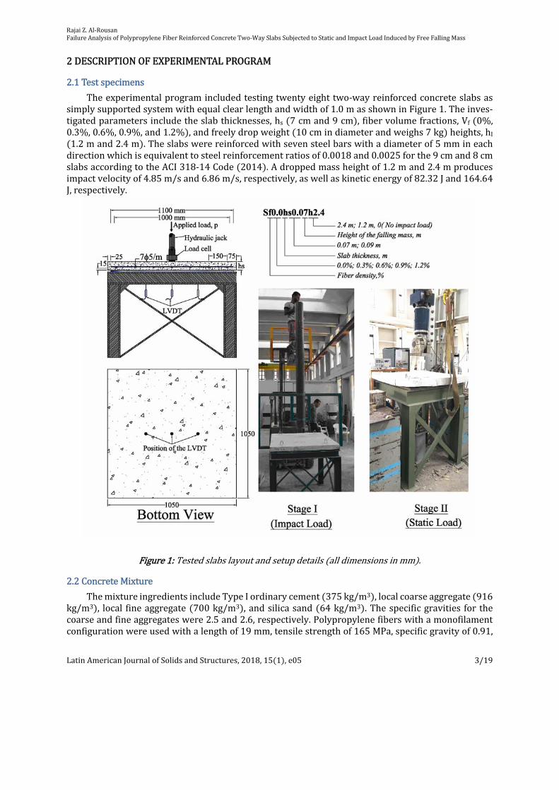
Theexperimentalprogramincludedtestingtwentyeighttwo‐wayreinforcedconcreteslabsassimplysupportedsystemwithequalclearlengthandwidthof1.0masshowninFigure1.Theinves‐tigatedparametersincludetheslabthicknesses,hs 7cmand9cm ,fibervolumefractions,Vf 0%,0.3%,0.6%,0.9%,and1.2% ,andfreelydropweight 10cmindiameterandweighs7kg heights,hI1.2mand2.4m .Theslabswerereinforcedwithsevensteelbarswithadiameterof5mmineachdirectionwhichisequivalenttosteelreinforcementratiosof0.0018and0.0025forthe9cmand8cmslabsaccordingtotheACI318‐14Code 2014 .Adroppedmassheightof1.2mand2.4mproducesimpactvelocityof4.85m/sand6.86m/s,respectively,aswellaskineticenergyof82.32Jand164.64J,respectively.
Figure1:Testedslabslayoutandsetupdetails alldimensionsinmm .
2.2ConcreteMixture
ThemixtureingredientsincludeTypeIordinarycement 375kg/m3 ,localcoarseaggregate 916kg/m3 , local fineaggregate 700kg/m3 ,andsilicasand 64kg/m3 .Thespecificgravities for thecoarseandfineaggregateswere2.5and2.6,respectively.Polypropylenefiberswithamonofilamentconfigurationwereusedwithalengthof19mm,tensilestrengthof165MPa,specificgravityof0.91,

RajaiZ.Al‐RousanFailureAnalysisofPolypropyleneFiberReinforcedConcreteTwo‐WaySlabsSubjectedtoStaticandImpactLoadInducedbyFreeFallingMass
LatinAmericanJournalofSolidsandStructures,2018,15 1 ,e05 4/19
excellentalkaliresistance,abilityindecreasingdryingandplasticshrinkage,abilityinincreasingim‐pactresistanceofyoungconcrete,ability toreinforcedconcretebyactingmechanicallywithmulti‐dimensionalfibernetworkcoatedwithmortar.AlltheingredientsweremixedconsistentlyandthenthefiberswerefeedingmanuallytoensuretheuniformdistributionoffibersintheconcretemixtureasshowninFigure2.Thentheconcreteisplacedinthewoodenmolds,vibratingthem,straighteningthetopoftheconcretespecimen,de‐moldingthespecimensfor24hoursaftercasting,andplacingthespecimensinlime‐saturatedwaterfor28daysforcuring.
Figure2:Mixingprocedureofthetestedtwowayslab
2.3TestSetupandInstrumentation
TheRCtwo‐wayslabsweretestedfirstlyunderimpactload Asteelballof7kgmasswithadjust‐ableheightsof1.2mto2.4misallowedtofallfreelythrough150mmindiameterhollowtubememberplacedverticallytostickthetopsurfaceofthetestedtwowayslabsatthecenter byusingaspecialdesignsetupconsistsofsteelmemberswithI‐sectionjoinedtogethertoprovideahorizontalplatformtogivesimplysupportedconditionforthetwowayslabasshowninFigure1 Stage1 .Then,allslabswereloadeduptofailureusingahydraulicjackcentrallypositionedatthetopoftheslabasshowninFigure1 Stage2 .Thereferenceslabsthathavenotsubjectedtoimpactloadwerejustloadeduptofailure Stage2 .Asquaresteelplatewithathicknessof50mmandasidelengthof200mmwasusedtosimulatetheacolumnwith200mmsidesasshowninFigure1.Theappliedloadwasmeasuredbyusingloadcellandthreelinearvariabledifferentialtransformers LVDT wereplacedatspecificloca‐tiontomeasurethedeflectionprofileofthetestedslabsasshowninFigure1.
3RESULTSANDDISCUSSION
3.1ConcreteStrengthResults
Figure3showsthestress‐straindiagramsfortheconcretewithdifferentfibervolumefractionsaswellasthecompressivestrength,splittingtensilestrength,andmodulusofelasticity.Inspectionof

RajaiZ.Al‐RousanFailureAnalysisofPolypropyleneFiberReinforcedConcreteTwo‐WaySlabsSubjectedtoStaticandImpactLoadInducedbyFreeFallingMass
LatinAmericanJournalofSolidsandStructures,2018,15 1 ,e05 5/19
Figure3revealsthattheslopeofthestress‐straincurveislinearup young’smodulesofelasticity toabout30–40%oftheultimatecompressivestrength,afterthatthecurvesbecomenon‐linearduetotheinitiationofthemicrocracksatthepaste‐aggregateinterface.Theultimatestressoccurredaftertheformulationofthelargecrackwithintheconcrete.Also,Figure3showsthatthemaximumcom‐pressivestrength f’c ,splittingtensilestrength fr ,andyoung’smodulesofelasticity Ec increasedwiththeincreaseoftheincreasingofpolypropylenecontentaccordingtoASTM‐C39,ASTMC496,andASTM‐C469 ASTM 2004 , respectively.The results also show that thepolypropylene fibershadhighereffectonthetensilestrengthanddynamicmodulesofelasticitythanthecompressivestrength.
Strain,
0 2000 4000 6000 8000
Stre
ss, M
Pa
0
10
20
30
40
50Fiber density,0.9%
Fiber density,1.2%
Fiber density,0.6%
Fiber density,0.3%
Fiber density,0%
Fiber density,%0
0.30.60.91.2
f /c,MPa38.940.842.444.347.1
fr,MPa2.923.133.323.463.77
Ec,MPa1662617934190242048121617
Figure3:Stress‐straindiagramsandmechanicalpropertiesofconcrete/
cf :compressivestrength, rf :
splittingtensilestrength,and cE :young’smodulesofelasticity
3.2AnalysisofFailureModeandUltimateLoadCapacity
Basedontheexperimentalresults,alltestedslabswerefailedinthepunchingshearmodeandflexuralcracksstarted fromthe loadingsteelplateandextendeduntil theedgesof the testedslab.Punchingshearmodeorfailurewasbrittlefailurewhichoccurredneartheloadingsteelplate com‐pressionfaceortopsurface attheultimatefailureload,followedbythedevelopmentofapunchingshearfailureconeatthetensileface Bottomsurface .Figures4‐6showthetypicalpunchingshearfailureonthecompressionfaceandtensileface.InspectionofFigure4revealsthatthe90mmslabthicknesshadaremarkableimpactontheflexuralcracksandpunchingshearconethan70mmslabthicknessbydecreasing thenumberof the flexural cracks Tensile face andsmallpunchingshearcone.Also,Figure5showsthatslabssubjectedtoimpacthadmoreflexuralcracksandlargepunchingshearconethanslabsnotsubjectedtoimpact.Inaddition,Figure6showstheincreasingoffibervol‐umedecreasedthenumberofflexuralcrackandthesizeofpunchingshearconebecausethefiberscontributionintheresistingoftheappliedforcesuntilthefiberswerepulledoutfromtheconcrete.Additionally,theoccupationoffibersinstretchingthefailedbottomsurface tensionface oftheslabawayfromtheloadingsteelplatethusincreasedtheirpunchingshearcapacity.

RajaiZ.Al‐RousanFailureAnalysisofPolypropyleneFiberReinforcedConcreteTwo‐WaySlabsSubjectedtoStaticandImpactLoadInducedbyFreeFallingMass
LatinAmericanJournalofSolidsandStructures,2018,15 1 ,e05 6/19
Figure4:Effectofslabthicknessoncrackpatterns
Figure5:Effectofimpactloadoncrackpatterns
Figure6:Effectoffibervolumeoncrackpatterns

RajaiZ.Al‐RousanFailureAnalysisofPolypropyleneFiberReinforcedConcreteTwo‐WaySlabsSubjectedtoStaticandImpactLoadInducedbyFreeFallingMass
LatinAmericanJournalofSolidsandStructures,2018,15 1 ,e05 7/19
Table1:Specimens’DetailsandTestResults
SlabPercentoffibersbyvolume Vf
Slabthickness hs ,m
Heightofthefallingmass hI ,m
Ultimate punchingshearload VR ,kN
Toughness,kN.mm
Sf0.0t0.07h0 0
0.07
None
88.9 1588
Sf0.3t0.07h0 0.30% 93.4 1852
Sf0.6t0.07h0 0.60% 96.1 2094
Sf0.9t0.07h0 0.90% 100.7 2470
Sf1.2t0.07h0 1.2% 108.4 2859
Sf0.0t0.09h0 0
0.09
120.1 2169
Sf0.3t0.09h0 0.30% 126.1 2519
Sf0.6t0.09h0 0.60% 128.8 2671
Sf0.9t0.09h0 0.9% 135.3 3076
Sf1.2t0.09h0 1.20% 144.8 3410
Sf0.0t0.07h1.2 0
0.07 1.2
61.8 1432
Sf0.3t0.07h1.2 0.30% 67.8 1768
Sf0.6t0.07h1.2 0.60% 74.9 2028
Sf0.9t0.07h1.2 0.90% 83.0 2335
Sf1.2t0.07h1.2 1.2% 91.0 2616
Sf0.0t0.07h2.4 0
0.07
2.4
58.1 1339
Sf0.3t0.07h2.4 0.30% 63.9 1658
Sf0.6t0.07h2.4 0.60% 70.4 1982
Sf0.9t0.07h2.4 0.90% 77.9 2285
Sf1.2t0.07h2.4 1.2% 85.5 2528
Sf0.0t0.09h2.4 0
0.09
80.7 1813
Sf0.3t0.09h2.4 0.30% 88.9 2203
Sf0.6t0.09h2.4 0.60% 94.0 2526
Sf0.9t0.09h2.4 0.90% 105.2 2932
Sf1.2t0.09h2.4 1.2% 116.6 3367
Note:Toughnessisdefinedastheareaundertheloadversusdeflectioncurve
Figure7:Effectoffibervolumepercentageandimpactloadonpunchingshearload

RajaiZ.Al‐RousanFailureAnalysisofPolypropyleneFiberReinforcedConcreteTwo‐WaySlabsSubjectedtoStaticandImpactLoadInducedbyFreeFallingMass
LatinAmericanJournalofSolidsandStructures,2018,15 1 ,e05 8/19
Table1andFigure7showthesummarizedresultsandtheeffectoffibervolumepercentageandimpactloadonpunchingshearloadofthetestedslabs.InspectionofFigure7revealsthattheultimatepunchingshearcapacityofcontrolslab slabsnotsubjectedtoimpact generally increasesandthedegradationinslabstrengthduetoimpactloaddecreaseswiththeincreasingfibervolumepercentage.AddingPFRin0.3to1.2%byvolumefractionincreasedtheultimatepunchingcapacitywithrespecttoslabwithoutPFRbyabout5to22%,respectively.While, theslabthickness hs 90mm hasastrongimpactontheultimatepunchingshearcapacitywithanenhancementof35%withrespecttoslabwithathicknessof70mm.Inaddition,theimpact loadataheightof1.2mand2.4mcreateddegradationintheultimatepunchingshearcapacityof30.5%and34.6%,respectively,aswellastheefficiencyof fiber inabsorbingof impact loadordecreasingtheultimate loadcapacitydegradation30.5%to16.1% isincreasedwiththeincreasingofPFRpercentage.
Figure8:Typicalloadversusdisplacementcurves
3.3LoadDeflectionBehavior
Figure8 a‐c showstheeffectoftheimpactload,slabthickness,andfibervolumeontheloaddisplacementbehavior,stiffness,andtoughness.Thestiffnessisdefinedastheslopeofthepartbe‐tweentheinitiationofthefirstcrack reachingthetensilestrengthoftheconcrete andtheloadat
RajaiZ.Al‐RousanFailureAnalysisofPolypropyleneFiberReinforcedConcreteTwo‐WaySlabsSubjectedtoStaticandImpactLoadInducedbyFreeFallingMass
LatinAmericanJournalofSolidsandStructures,2018,15 1 ,e05 9/19
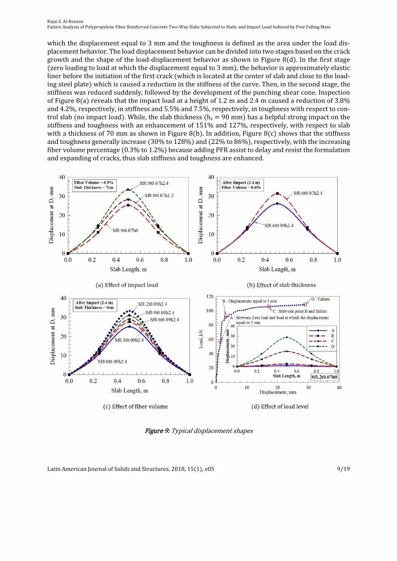
whichthedisplacementequalto3mmandthetoughnessisdefinedastheareaundertheloaddis‐placementbehavior.Theloaddisplacementbehaviorcanbedividedintotwostagesbasedonthecrackgrowthandtheshapeoftheload‐displacementbehaviorasshowninFigure8 d .Inthefirststagezeroloadingtoloadatwhichthedisplacementequalto3mm ,thebehaviorisapproximatelyelasticlinerbeforetheinitiationofthefirstcrack whichislocatedatthecenterofslabandclosetotheload‐ingsteelplate whichiscausedareductioninthestiffnessofthecurve.Then,inthesecondstage,thestiffnesswasreducedsuddenly,followedbythedevelopmentofthepunchingshearcone.InspectionofFigure8 a revealsthattheimpactloadataheightof1.2mand2.4mcausedareductionof3.8%and4.2%,respectively,instiffnessand5.5%and7.5%,respectively,intoughnesswithrespecttocon‐trolslab noimpactload .While,theslabthickness hs 90mm hasahelpfulstrongimpactonthestiffnessandtoughnesswithanenhancementof151%and127%,respectively,withrespecttoslabwithathicknessof70mmasshowninFigure8 b .Inaddition,Figure8 c showsthatthestiffnessandtoughnessgenerallyincrease 30%to128% and 22%to86% ,respectively,withtheincreasingfibervolumepercentage 0.3%to1.2% becauseaddingPFRassisttodelayandresisttheformulationandexpandingofcracks,thusslabstiffnessandtoughnessareenhanced.
Figure9:Typicaldisplacementshapes

RajaiZ.Al‐RousanFailureAnalysisofPolypropyleneFiberReinforcedConcreteTwo‐WaySlabsSubjectedtoStaticandImpactLoadInducedbyFreeFallingMass
LatinAmericanJournalofSolidsandStructures,2018,15 1 ,e05 10/19
3.4DeflectionProfile
Assessmentofthedisplacementprofileofthetestedslabsprovidesfurtherinformation quanti‐tativemeasure onthetopicoftheeffectoftestedparameters Figure9 ontheglobalstructuralbe‐haviorthatisnotdirectlyobviousfromstudyingoftheload‐displacementbehaviorandultimatemid‐pointdisplacement.Figure9 a‐c showstheeffectoftheimpactload,slabthickness,andfibervolumeonthedisplacementprofile.WhileFigure9 d showsthedisplacementprofileatdifferentloadvalueA:pointbetweenzeroloadandtheloadatwhichthedisplacementequalto3mm;B:pointatdis‐placementequalto3mm;C:pointbetweentheBandfailurepoint;andD:pointatfailureatultimatepunchingloadcapacity.InspectionofFigure9 a revealsthattheimpactloadataheightof2.4mhadthehighestdisplacementprofilespecificallyatthemid‐pointcomparingwithimpactloadataheightof1.2m.Thisconclusionisobservedthesameinthemodeoffailurewherethatslabssubjectedtoimpactataheightof2.4hadmoreflexuralcracksandlargepunchingshearconethanslabssubjectedtoimpactataheightof1.2m.Whilethedisplacementatthequarter‐pointisalmostequalforbothimpactheights.Inadditiontheslabthicknesshadthesameeffectonthedisplacementprofile mid‐pointandquarter‐point astheimpactloadanddecreasedwiththeincreasingoftheslabthicknessasshowninFigure9 b .IncomparingallofthedisplacementprofileshowedinFigure9 c ,itcanbeseenthatthePFRweresuccessfulinjustifyingthegrowthoflocalizedfailuresintermsofnumberofflexuralcrackandthesizeofthepunchingshearcone,thePFRslabsexhibiteddisplacementprofileinwhichdisplacementweremoreconsistentlydistributedand,asaresult,wereabletoachievelargerdisplace‐mentprofileatfailure.
4EMPIRICALMODEL
4.1PunchingShearModelforTwo‐WayRCSlabsSubjectedtoImpactLoad
PredictionofpunchingshearstrengthinRCtwo‐wayslabswithdifferentslabthicknesses,fibervolumefractions,andfreelydropweightheights Impact load is fundamental inordertoproposestructuraldesignproceduresforstructuressubjectedtoimpactload.Thus,anempiricalmodelwasproposedtopredictthepunchingshearstrengthoftwo‐wayRCslabssubjectedtoimpactloadasafunctionoftestedparameters.Mostmodelsfoundedintheliteratureanddesigncodesbasetheirver‐ificationsonacriticalsectiontofindthepunchingshearstrengthofnon‐impactedRCslabswithoutshear reinforcement Lorena et al. 2016 ,Micael et al. 2015 ,Ong et al. 1997 , Kurihashi et al.2006 ,Zhangetal. 2007 ,ChengandParra‐Montesinos 2010 ,Mayaetal. 2012 ,ACICommittee318 2014 ,FédérationInternationaleduBéton FIB‐Vol.1 2010a ,FédérationInternationaleduBéton FIB‐Vol.2 2010b ,JSCE 2007 ,Choietal. 2007 ,Higashiyamaetal. 2011 ,ASTM 2004 ,SelcukandFrank 2009 .Eq. 1 showstheACI318‐14 2014 expressionforcircularorsquarecol‐umnsoftwowayslabmoderaterelativetotheconcretecompressivestrengthandthicknessoftheslab
/33.0 coR fdbV 1
whereVRisthepunchingshearcapacityoftwo‐wayslabsatcriticalsectionlocatedatd/2fromthefaceofthesquareorcircularcolumn.distheeffectivedepthoftheslab,f′cistheconcretecompressivestrengthat28days,andboistheperimeterofthecriticalsection.Basedontheaboveequation,Eq. 2 canbeusedtodescribethepunchingshearcapacityofRCtwo‐wayslabssubjectedto impactwithsomemodificationsasfollowing:
/coR fdbV 2
RajaiZ.Al‐RousanFailureAnalysisofPolypropyleneFiberReinforcedConcreteTwo‐WaySlabsSubjectedtoStaticandImpactLoadInducedbyFreeFallingMass
LatinAmericanJournalofSolidsandStructures,2018,15 1 ,e05 11/19
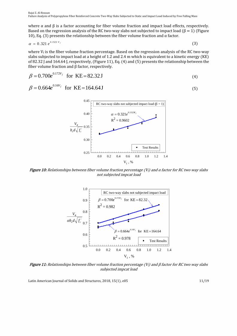
whereαandβisafactoraccountingforfibervolumefractionandimpactloadeffects,respectively.BasedontheregressionanalysisoftheRCtwo‐wayslabsnotsubjectedtoimpactload β 1 Figure10 ,Eq. 3 presentstherelationshipbetweenthefibervolumefractionandαfactor.
fVe 1523.0321.0 3
whereVfisthefibervolumefractionpercentage.BasedontheregressionanalysisoftheRCtwo‐wayslabssubjectedtoimpactloadataheightof1.2and2.4mwhichisequivalenttoakineticenergy KE of82.32Jand164.64J,respectively, Figure11 ,Eq. 4 and 5 presentstherelationshipbetweenthefibervolumefractionandβfactor,respectively.
J 82.32 KEfor 0.700 172.0 fVe 4
J 164.64 KEfor 0.664 16.0 fVe 5
Vf , %
0.0 0.2 0.4 0.6 0.8 1.0 1.2 1.40.25
0.30
0.35
0.40
0.45
Test Results
R2 = 0.9602
RC two-way slabs not subjected impact load ( = 1)
/co
R
fdb
V
fVe
1523.0321.0
Figure10:Relationshipsbetweenfibervolumefractionpercentage Vf andαfactorforRCtwowayslabs
notsubjectedimpcatload
/co
R
fdb
V
Vf , %
0.0 0.2 0.4 0.6 0.8 1.0 1.2 1.40.5
0.6
0.7
0.8
0.9
1.0
Test ResultsR2 = 0.978
RC two-way slabs not subjected impact load
164.64 KEfor 0.66416.0 fV
e
82.32 KEfor 0.700 172.0 fV
e
R2 = 0.982
Figure11:Relationshipsbetweenfibervolumefractionpercentage Vf andβfactorforRCtwowayslabs
subjectedimpcatload

RajaiZ.Al‐RousanFailureAnalysisofPolypropyleneFiberReinforcedConcreteTwo‐WaySlabsSubjectedtoStaticandImpactLoadInducedbyFreeFallingMass
LatinAmericanJournalofSolidsandStructures,2018,15 1 ,e05 12/19
ThusthepunchingshearstrengthoftheRCtwo‐wayslabssubjectedtoimpactcanbedefinedbythefollowingequations
impact) (No 0 KEfor 321.0 /1523.0 coV
R fdbeV f 6
J 32.28 KEfor 213.0 /3123.0 coV
R fdbeV f 7
J 64.164 KEfor 225.0 /324.0 coV
R fdbeV f 8
Table2:ExistingPunchingShearStrengthModels
Authors PunchingShearStrengthModel
NarayananandDarwish 1987
sf
fffs
f
ffbspR he
d
laVh
d
lafV 3455.01002.06.141.01624.0
fibers duoformfor 0.1
fibers crimpedfor 75.0
fibers roundfor 5.0
fa
ShaabanandGesund 1994 /4567.027.325.06.0 cfR fddeVV
Harajlietal.1995 /4075.033.0 cfR fddeVV
Higashiyamaetal. 2011
dd
laVde
d
laVfV
f
fff
f
fffbpcdrpdR
32.0141.0
MPaff cpcd 2.12.0 / , 5.11000
4 dd , 5.11003 p
der /25.01
11
PresentStudy /1523.0 4321.0 cV
R fddeeV f
Note:wherefspistheindirectcylindertensilestrengthoffiberreinforcedconcrete,τb 4.15MPaistheaveragefiber‐matrixinterfacialbondstress,αfisafactordependingofthefibergeometry,lfisthelengthofthefiber,dfisthediameterofthefiber,Vfisthevolumeofthefiber,distheeffectivedepthoftheslab,eisthecolumnsidelength,ρisthesteelreinforcementratio,andf’cistheconcretecompressivestrengthat28days
Table3:Predictedtotestpunchingshearstrength
Slab
VR,kN
TestedNarayananand
Darwish1987
ShaabanandGesund 1994
Harajlietal. 1995
Higashiyamaetal. 2011
PresentStudy
Sf0.0t0.07h0 88.9 96.8 93.4 90.6 113.5 88.1
Sf0.3t0.07h0 93.4 100.2 97.4 96.8 123.5 92.2
Sf0.6t0.07h0 96.1 103.6 101.5 102.9 132.9 96.5
Sf0.9t0.07h0 100.7 106.8 105.5 109.1 141.7 101.1
RajaiZ.Al‐RousanFailureAnalysisofPolypropyleneFiberReinforcedConcreteTwo‐WaySlabsSubjectedtoStaticandImpactLoadInducedbyFreeFallingMass
LatinAmericanJournalofSolidsandStructures,2018,15 1 ,e05 13/19
Sf1.2t0.07h0 108.4 109.9 109.5 115.3 149.9 105.8
Sf0.0t0.09h0 120.1 144.8 127.4 123.5 162.0 120.2
Sf0.3t0.09h0 126.1 150.0 132.9 132.0 176.3 125.8
Sf0.6t0.09h0 128.8 155.0 138.4 140.4 189.8 131.7
Sf0.9t0.09h0 135.3 159.8 143.9 148.8 202.3 137.8
Sf1.2t0.09h0 144.8 164.4 149.4 157.2 214.0 144.3
Predicted/Test 1.123 1.049 1.063 1.397 0.999
Coefficientofvariation 0.061 0.017 0.027 0.051 0.014
CorrelationCoefficient 0.978 0.995 0.993 0.991 0.997
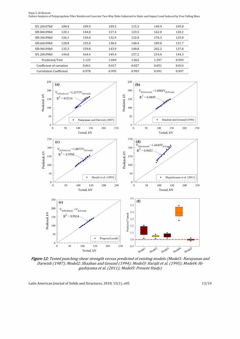
Figure12:Testedpunchingshearstrengthversuspredictedofexistingmodels Model1:Narayananand
Darwish 1987 ;Model2:ShaabanandGesund 1994 ;Model3:Harajlietal. 1995 ;Model4:Hi‐gashiyamaetal. 2011 ;Model5:PresentStudy

RajaiZ.Al‐RousanFailureAnalysisofPolypropyleneFiberReinforcedConcreteTwo‐WaySlabsSubjectedtoStaticandImpactLoadInducedbyFreeFallingMass
LatinAmericanJournalofSolidsandStructures,2018,15 1 ,e05 14/19
4.2PredictabilityofVariousTheoreticalModels
TofindthepredictabilityandtheaccuracyoftheproposedmodelinEq. 6 ,itwascomparedwiththepunchingshearmodelswhicharethemostvalidandaccuratemodelforproposedmodel Nara‐yanan andDarwish 1987 ; Shaaban andGesund 1994 ;Harajli et al. 1995 ;Higashiyama et al.2011 asshowninTable2.Theaveragevalue predicted/tested ,coefficientofvariationandcorre‐lationcoefficientforpunchingshearcapacitypredictedbyusingvarioustheoreticalmodelsareshowninTable3.InspectionofTable3revealsthatthepredictedvalueShaabanandGesund 1994 andHa‐rajlietal. 1995 isclosedtothetestedvaluewithanaveragevalue predicted/tested of1.049and1.063,respectively,aswellasthecorrelationcoefficientsaremorethan0.95whichreflectsthatthebehaviorofthetestdataarewelldescribedbythesemodels.Also,NarayananandDarwish 1987 haveanacceptable predicted/tested of1.123.While,Higashiyamaetal. 2011 isoverestimatedthepunchingshearcapacitywithanaveragevalueof1.397.Figure12showsthetestedpunchingshearstrengthversuspredictedofexistingmodels.InspectionofFigure12 a‐d revealsthatthetheoreticalmodelsareoverestimatedthepunchingshearstrengthofthetestedslabswithhigherR2morethan90%.Inaddition,Figure12 f showsthattheproposedmodelprovidesthehighestnumberofpredic‐tionsof predicted/tested intheintervals 0.98‐1.02 andtheHigashiyamaetal. 2011 havethelow‐estnumberofpredictionsof predicted/tested intheintervals 1.28‐1.49 .
4.3PredictabilityoftheProposedModel
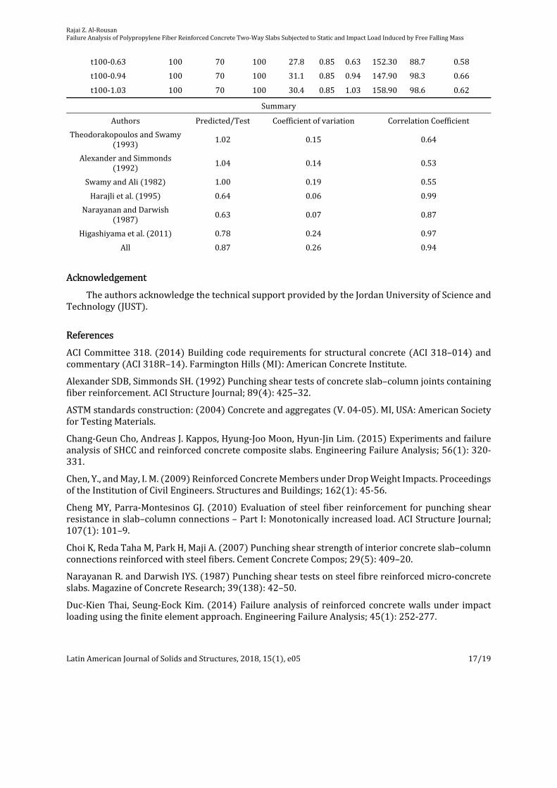
Theproposedmodelischeckedagainstpublishedexperimentalresultsbypredictingthepunch‐ingshearstrengthasshowninTable4.Inaddition,theaveragevalue predicted/tested ,coefficientofvariationandcorrelationcoefficientfortheexperimentalresultspresentedbyTheodorakopoulosandSwamy 1993 ,AlexanderandSimmonds 1992 ,SwamyandAli 1982 ,Harajlietal. 1995 ,NarayananandDarwish 1987 ,andHigashiyamaetal. 2011 aresummarizedinTable4.InspectionofTable4revealsthattheaveragepredictionerrorrangedfrom2%forTheodorakopoulosandSwamy1993 to37%forNarayananandDarwish 1987 ,wheretheaveragevalueandtheCorrelationCoef‐ficient forall theexperimentalresultswasapproximatelyequal87%and94%,respectively,whichshowsthattheproposedmodelhasagoodprospectivetopredictpunchingshearstrength
5CONCLUSIONS
Basedontheresultsandobservations,thefollowingconclusionsaredrawn:1.Theincreasinginslabthicknesshadanotableeffectontheflexuralcracksandpunchingshear
conebydecreasingthenumberoftheflexuralcracks Tensileface andthesizeofpunchingshearconewhiletheincreasinginimpactloadandthefibervolumeareincreasedthenumberofthenumberofflexuralcracksandthesizeofpunchingshearcone.
2.Theincreasinginslabthicknessof28%hadanenhancementoftheultimatepunchingshearcapacityof35%andtheaddingPFRin0.3to1.2%byvolumefractionenhancedtheultimatepunchingcapacitywith5to22%whiletheimpactloadataheightof1.2mand2.4mcreateddegradationintheultimatepunchingshearcapacityof30.5%and34.6%.
3.Theimpactloadcausedareductionoflessthan10%instiffnessandtoughnessofthetestedslabsbuttheslabthicknessenhancedthestiffnessandtoughnesswithanenhancementof151%and127%,respectively,aswellasthestiffnessandtoughnessincreased 30%to128% and22%to86% ,respectively,withtheincreasingfibervolumepercentageof0.3%to1.2%.
4.ThePFRslabsexhibiteddisplacementprofileinwhichdisplacementweremoreconsistentlydistributedand,asaresult,wereabletoachievelargerdisplacementprofileatfailure.
5.Theproposedempiricalmodelwasingoodagreementwiththeoreticalmodelsexperimentalresultsavailableinliteratureinpredictingtheultimatepunchingshearcapacityoftwowayslabsnotsubjectedtoimpact.

RajaiZ.Al‐RousanFailureAnalysisofPolypropyleneFiberReinforcedConcreteTwo‐WaySlabsSubjectedtoStaticandImpactLoadInducedbyFreeFallingMass
LatinAmericanJournalofSolidsandStructures,2018,15 1 ,e05 15/19
Table4:LiteratureExperimentaldataandpunchingshearstrengthprediction
Specimen h,mm d,mm e,mm/
cf ,
MPaρ,% Vf,%
Vexp,kN
VPre‐dicted,kN
(Tested)
)(Predicted
R
R
V
V
TheodorakopoulosandSwamy 1993
FS‐1 125 100 150 35.4 0.56 0.00 173.5 191 1.10
FS‐2 125 100 150 34.0 0.56 0.50 225 202 0.90
FS‐3 125 100 150 35.6 0.56 1.00 247.4 223 0.90
FS‐4 125 100 150 35.7 0.56 1.00 224.4 223.3 1.00
FS‐5 125 100 150 38.0 0.37 1.00 198.1 230.4 1.16
FS‐6 125 100 150 35.7 0.37 1.00 174.5 223.3 1.28
FS‐7 125 100 150 36.6 0.37 1.00 192.4 226.1 1.18
FS‐19 125 100 150 34.5 0.37 0.00 136.5 188.5 1.38
FS‐20 125 100 150 37.0 0.37 1.00 211 227.4 1.08
FS‐8 125 100 100 36.7 0.56 0.00 150.3 155.6 1.04
FS‐9 125 100 100 35.6 0.56 1.00 216.6 178.4 0.82
FS‐10 125 100 200 36.4 0.56 0.00 191.4 232.4 1.21
FS‐11 125 100 200 34.2 0.56 1.00 259.8 262.3 1.01
FS‐12 125 100 150 36.1 0.56 1.00 217.5 224.6 1.03
FS‐13 125 100 150 33.5 0.56 1.00 235.5 216.4 0.92
FS‐14 125 100 150 35.0 0.56 1.00 239.5 221.1 0.92
FS‐15 125 100 150 31.2 0.56 1.00 238 208.8 0.88
FS‐16 125 100 150 27.9 0.56 1.00 227.8 197.4 0.87
FS‐17 125 100 150 46.8 0.56 1.00 268.4 255.7 0.95
FS‐18 125 100 150 14.2 0.56 1.00 166 140.9 0.85
AlexanderandSimmonds 1992
P11F0 155 132.7 200 33.2 0.5 0.00 257.0 326.6 1.27
P11F31 155 132.7 200 35.8 0.5 0.39 324.0 359.9 1.11
P11F66 155 132.7 200 35.0 0.5 0.84 345.0 381.1 1.10
P38F0 155 105.7 200 38.1 0.63 0.00 264.0 256.1 0.97
P38F34 155 105.7 200 38.4 0.63 0.43 308.0 274.5 0.89
P38F69 155 105.7 200 38.5 0.63 0.88 330.0 294.4 0.89
SwamyandAli 1982
S‐1 125 100 150 37.80 0.56 0.00 197.7 197.4 1.00
S‐2 125 100 150 39.00 0.56 0.60 243.6 219.6 0.9
S‐3 125 100 150 37.80 0.56 0.90 262.9 226.3 0.86
S‐4 125 100 150 36.90 0.56 1.20 281.0 234.1 0.83
S‐5 125 100 150 37.80 0.56 0.90 267.2 226.3 0.85
S‐6 125 100 150 38.00 0.56 0.90 239.0 226.9 0.95
S‐7 125 100 150 38.90 0.74 0.00 221.7 200.2 0.90
S‐13 125 100 150 39.30 0.74 0.90 236.7 230.8 0.98

RajaiZ.Al‐RousanFailureAnalysisofPolypropyleneFiberReinforcedConcreteTwo‐WaySlabsSubjectedtoStaticandImpactLoadInducedbyFreeFallingMass
LatinAmericanJournalofSolidsandStructures,2018,15 1 ,e05 16/19
S‐12 125 100 150 36.80 0.74 0.90 249.0 223.3 0.90
S‐11 125 100 150 37.10 0.74 0.90 262.0 224.2 0.86
S‐8 125 100 150 41.10 0.74 0.90 255.7 236.0 0.92
S‐16 125 100 150 38.90 0.56 0.90 213.0 229.6 1.08
S‐10 125 100 150 38.90 0.46 0.90 203.0 229.6 1.13
S‐9 125 100 150 38.90 0.37 0.90 179.3 229.6 1.28
S‐19 125 100 150 38.90 0.37 0.00 130.7 200.2 1.53
Harajlietal. 1995
A1 55 39 100 29.60 1.12 0.00 58.8 37.9 0.64
A2 55 39 100 30.00 1.12 0.45 63.6 40.8 0.64
A3 55 39 100 31.40 1.12 0.80 73.1 44.1 0.60
A4 55 39 100 24.60 1.12 1.00 64.7 40.2 0.62
A5 55 39 100 20.00 1.12 2.00 58.3 42.2 0.72
B1 75 55 100 31.40 1.12 0.00 91.8 61.3 0.67
B2 75 55 100 31.40 1.12 0.45 105.9 65.7 0.62
B3 75 55 100 31.80 1.12 0.80 108.4 69.7 0.64
B4 75 55 100 29.10 1.12 1.00 108.8 68.8 0.63
B5 75 55 100 29.20 1.12 2.00 134.5 80.2 0.60
NarayananandDarwish 1987
S1 60 45 100 43.3 1.84 0.00 86.50 55.1 0.64
S2 60 45 100 52.1 1.84 0.25 93.40 62.8 0.67
S3 60 45 100 44.7 1.84 0.50 102.00 60.4 0.59
S4 60 45 100 46.0 1.84 0.75 107.50 63.7 0.59
S5 60 45 100 53.0 1.84 1.00 113.60 71.0 0.63
S6 60 45 100 53.0 1.84 1.25 122.20 73.8 0.60
S7 60 45 100 47.0 1.6 1.00 92.60 66.9 0.72
S8 60 45 100 45.3 2.08 1.00 111.10 65.7 0.59
S9 60 45 100 43.5 2.3 1.00 111.30 64.3 0.58
S10 60 45 100 47.6 2.53 1.00 111.30 67.3 0.60
S11 60 45 100 29.8 1.84 1.00 82.10 53.3 0.65
S12 60 45 100 32.4 1.84 1.00 84.90 55.5 0.65
Higashiyamaetal. 2011
t100‐0.67 100 70 100 24.6 0.85 0.67 137.50 83.9 0.61
t140‐0.67 140 110 100 24.6 0.54 0.67 210.20 162.9 0.78
t180‐0.67 180 150 100 24.6 0.4 0.67 297.60 264.5 0.89
t100‐0.72 100 65 100 42.4 0.91 0.72 140.80 100.1 0.71
t140‐0.72 140 105 100 42.4 0.57 0.72 213.20 200.8 0.94
t180‐0.72 180 145 100 42.4 0.41 0.72 290.70 331.4 1.14
t100‐0.91 100 65 100 21.6 0.91 0.91 120.80 73.5 0.61
t140‐0.91 140 105 100 21.6 0.57 0.91 183.10 147.5 0.81
t180‐0.91 180 145 100 21.6 0.41 0.91 231.20 243.5 1.05
RajaiZ.Al‐RousanFailureAnalysisofPolypropyleneFiberReinforcedConcreteTwo‐WaySlabsSubjectedtoStaticandImpactLoadInducedbyFreeFallingMass
LatinAmericanJournalofSolidsandStructures,2018,15 1 ,e05 17/19
t100‐0.63 100 70 100 27.8 0.85 0.63 152.30 88.7 0.58
t100‐0.94 100 70 100 31.1 0.85 0.94 147.90 98.3 0.66
t100‐1.03 100 70 100 30.4 0.85 1.03 158.90 98.6 0.62
Summary
Authors Predicted/Test Coefficientofvariation CorrelationCoefficient
TheodorakopoulosandSwamy1993
1.02 0.15 0.64
AlexanderandSimmonds1992 1.04 0.14 0.53
SwamyandAli 1982 1.00 0.19 0.55
Harajlietal. 1995 0.64 0.06 0.99
NarayananandDarwish1987 0.63 0.07 0.87
Higashiyamaetal. 2011 0.78 0.24 0.97
All 0.87 0.26 0.94
Acknowledgement
TheauthorsacknowledgethetechnicalsupportprovidedbytheJordanUniversityofScienceandTechnology JUST .
References
ACICommittee318. 2014 Buildingcoderequirementsforstructuralconcrete ACI318–014 andcommentary ACI318R–14 .FarmingtonHills MI :AmericanConcreteInstitute.
AlexanderSDB,SimmondsSH. 1992 Punchingsheartestsofconcreteslab–columnjointscontainingfiberreinforcement.ACIStructureJournal;89 4 :425–32.
ASTMstandardsconstruction: 2004 Concreteandaggregates V.04‐05 .MI,USA:AmericanSocietyforTestingMaterials.
Chang‐GeunCho,AndreasJ.Kappos,Hyung‐JooMoon,Hyun‐JinLim. 2015 ExperimentsandfailureanalysisofSHCCandreinforcedconcretecompositeslabs.EngineeringFailureAnalysis;56 1 :320‐331.
Chen,Y.,andMay,I.M. 2009 ReinforcedConcreteMembersunderDropWeightImpacts.ProceedingsoftheInstitutionofCivilEngineers.StructuresandBuildings;162 1 :45‐56.
ChengMY,Parra‐MontesinosGJ. 2010 Evaluationof steelfiberreinforcement forpunchingshearresistanceinslab–columnconnections–PartI:Monotonicallyincreasedload.ACIStructureJournal;107 1 :101–9.
ChoiK,RedaTahaM,ParkH,MajiA. 2007 Punchingshearstrengthofinteriorconcreteslab–columnconnectionsreinforcedwithsteelfibers.CementConcreteCompos;29 5 :409–20.
NarayananR.andDarwishIYS. 1987 Punchingsheartestsonsteelfibrereinforcedmicro‐concreteslabs.MagazineofConcreteResearch;39 138 :42–50.
Duc‐KienThai,Seung‐EockKim. 2014 Failureanalysisof reinforcedconcretewallsunder impactloadingusingthefiniteelementapproach.EngineeringFailureAnalysis;45 1 :252‐277.
RajaiZ.Al‐RousanFailureAnalysisofPolypropyleneFiberReinforcedConcreteTwo‐WaySlabsSubjectedtoStaticandImpactLoadInducedbyFreeFallingMass
LatinAmericanJournalofSolidsandStructures,2018,15 1 ,e05 18/19
Duc‐KienThai,Seung‐EockKim. 2017 Numericalsimulationofpre‐stressedconcreteslabsubjectedtomoderatevelocityimpactloading.EngineeringFailureAnalysis;79 1 :820‐835
Fédération Internationale duBéton FIB . 2010a Model Code2010 –first complete draft, vol. 1,FédérationInternationaleduBéton,Bulletin55.Lausanne Switzerland .
Fédération InternationaleduBéton FIB . 2010b ModelCode2010–first completedraft, vol. 2,FédérationInternationaleduBéton,Bulletin55.Lausanne Switzerland .
HarajliMH,MaaloufD,KhatibH. 1995 Effectoffibersonthepunchingshearstrengthofslab–columnconnections.CementConcreteCompos;17 2 :161–70.
HigashiyamaH,OtaA,MizukoshiM. 2011 DesignequationforpunchingcapacityofSFRCslabs.In‐ternationalJournalofConcreteStructuresandMaterials;5 1 :35–42.
JSCE. 2007 Standardspecificationsforconcretestructures‐2007,Design.Tokyo Japan :JapanSoci‐etyofCivilEngineers.
Kennedy,R.P. 1976 AReviewofProceduresfortheAnalysisandDesignofConcreteStructurestoResistMissileImpactEffects.NuclearEngineeringandDesign;37 2 :183‐203.
Kurihashi,Y.;Taguchi,F.;Kishi,N.;andMikami,H. 2006 ExperimentalStudyonStaticandDynamicResponseofPVAShort‐FiberMixedRCSlab.fibProceedingsofthe2ndInternationalCongress,ID13‐20,Naples,Italy,10pp.
LorenaFrancesconi,LuisaPani,FlavioStochino. 2016 Punchingshearstrengthofreinforcedrecycledconcreteslabs.ConstructionandBuildingMaterials;127:248–263
MayaL.F.,FernándezRuiz,MuttoniA.,FosterS.J. 2012 Punchingshearstrengthofsteelfibrerein‐forcedconcreteslabs.EngineeringStructures;40 1 :83–94.
MicaelM.G.Inácio,AndréF.O.Almeida,DuarteM.V.Faria,VálterJ.G.Lúcio,AntónioPinhoRamos.2015 Punchingofhighstrengthconcreteflatslabswithoutshearreinforcement.EngineeringStruc‐tures;103:275–284.
Ong,K.C.G.;Basheerkhan,M.;andParamasivam,P. 1997 BehaviorofFiber‐ReinforcedConcreteSlabsunderLowVelocityProjectileImpact.HighPerformanceConcreteProceedings:ACIInternationalConference,Malaysia,SP‐172,V.M.Malhotra,ed.,AmericanConcreteInstitute,FarmingtonHills,MI:993‐1011.
SelcukSaatciandFrankJ.Vecchio. 2009 NonlinearFiniteElementModelingofReinforcedConcreteStructuresunderImpactLoads.ACIStructuralJournal;106 5 :717‐725.
ShaabanAM.GesundH. 1994 Punchingshearstrengthofsteelfiberreinforcedconcreteflatplates.ACIStructureJournal;91 4 :406–414.
ShujianYao,DuoZhang,XuguangChen,FangyunLu,WeiWang. 2016 ExperimentalandnumericalstudyonthedynamicresponseofRCslabsunderblastloading.EngineeringFailureAnalysis;66 1 :120‐129.
SwamyRN,Ali SAR. 1982 Punchingshearbehaviorof reinforcedslab–columnconnectionsmadewithsteelfiberconcrete.ACIStructureJournal;79 6 :392–406.
TheodorakopoulosDD,SwamyN. 1993 Contributionofsteelfiberstothestrengthcharacteristicsoflightweightconcreteslab–columnconnectionsfailinginpunchingshear.ACIStructureJournal;90 4 :342–55.
RajaiZ.Al‐RousanFailureAnalysisofPolypropyleneFiberReinforcedConcreteTwo‐WaySlabsSubjectedtoStaticandImpactLoadInducedbyFreeFallingMass
LatinAmericanJournalofSolidsandStructures,2018,15 1 ,e05 19/19
VimalKumar,M.A.Iqbal,A.K.Mittal 2017 .Experimentalinvestigationofprestressedandreinforcedconcrete plates under falling weight impactor, Thin‐Walled Structures; ISSN 0263‐8231,https://doi.org/10.1016/j.tws.2017.06.028.
WeiWang,DuoZhang,FangyunLu,Song‐chuanWang,FujingTang. 2013 .Experimentalstudyandnumericalsimulationofthedamagemodeofasquarereinforcedconcreteslabunderclose‐inexplo‐sion.EngineeringFailureAnalysis;27 1 :41‐51
Zhang,J.;Maalej,M.;andQuek,S.T. 2007 PerformanceofHybrid‐FiberECCBlast/ShelterPanelsSubjectedtoDropWeightImpact.JournalofMaterialsinCivilEngineering,ASCE;19 10 :855‐863.