Embed Size (px)
Citation preview

Dell Confidential
Client EngineeringClient Engineering
-
Amanuel M Abebaw
Advisor: Dr. El-MounayriDepartment of Mechanical Engineering
Purdue School of Engineering and Technology, IUPUI
Co-Advisor: Phil GilchrestDell inc.
August 30th 2005
Failure analysis of an LCD assembly
ME 597 Project I
Dell Confidential
Client EngineeringClient Engineering
-
Outline
ObjectiveIdentify the root causes of failureEngineering solutions
LimitationThis study only analyze the LCD assembly (the Mg
cover and LCD module) of the Notebook computer

Dell Confidential
Client EngineeringClient Engineering
-
Back ground
Definition of failure Paint lines , Paint spots, Scratches (light ,deep), dents, Screen discoloration on the surface of an LCD

Dell Confidential
Client EngineeringClient Engineering
-
Methodology
Step 1Define a bench mark
Step 2Investigating the characteristics of LCD
Step 3Finite element analysis
ANSYSPro|Mechanica
Step 4Identify failure causes
Step 5Suggest design improvement

Dell Confidential
Client EngineeringClient Engineering
-
Step 1- Defining a bench Mark
Dell Confidential
Client EngineeringClient Engineering
-
Step 2- Investigation of LCD
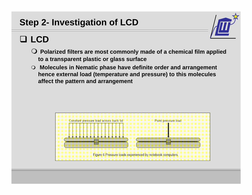
LCD Polarized filters are most commonly made of a chemical film applied
to a transparent plastic or glass surface Molecules in Nematic phase have definite order and arrangement hence external load (temperature and pressure) to this moleculesaffect the pattern and arrangement
Dell Confidential
Client EngineeringClient Engineering
-
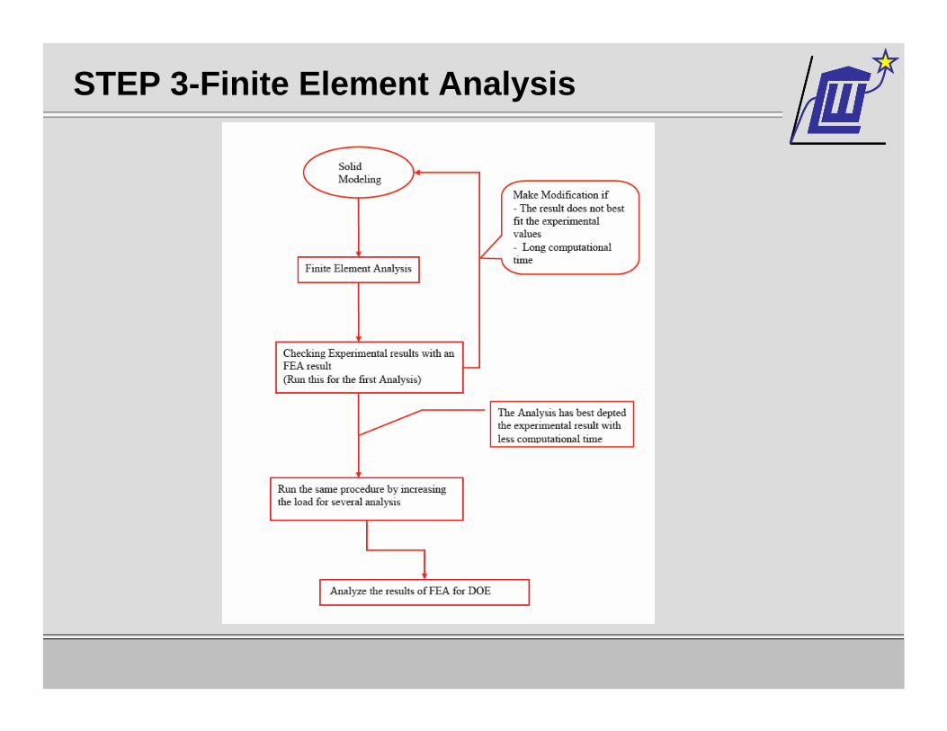
STEP 3-Finite Element Analysis
Dell Confidential
Client EngineeringClient Engineering
-
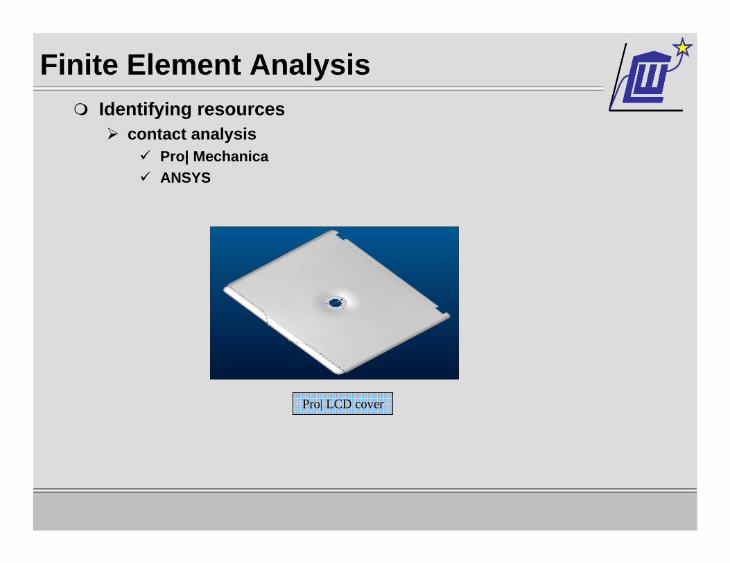
Finite Element Analysis Identifying resources
contact analysisPro| MechanicaANSYS
Pro| LCD cover

Dell Confidential
Client EngineeringClient Engineering
-
Contact Analysis
Pro|Mechanica Capability
MECHANICA allows you to refine the elements on the contacting surfaces in order to improve contact pressure results.This option is only available if the Single Pass Adaptiveconvergence method is requested.Friction between parts are not allowedLess control of mesh
FactSingle pass adaptive convergence is valid for small deflection theorySmall deflection theory becomes invalid when the model bends beyond 5 degrees.geometric nonlinear analysis (large deflection theory).

Dell Confidential
Client EngineeringClient Engineering
-
Contact Analysis ANSYS
CapabilityAllows us to refine mesh on contacting surfaces-more accurate resultsLarge deflection theory is valid for contact analysisAllows friction between the mating parts
Factcontact elements use a "target surface" and a "contact surface" to form a contact pair

Dell Confidential
Client EngineeringClient Engineering
-
Challengecontact element type
Node to node contact elements node-to-node contact elements is an extremely precise analysis of surface stresses To use node-to-node contact elements, you need to know the location of contact beforehand
Node to surface contact elementswell-suited for point-to-point, point-to-surface, or edge-to-surface contact applications
Surface to surface contact elementsProvide better contact results needed for typical engineering purposes, such as normal pressure and friction stress contour plots Have no restrictions on the shape of the target surface
---Contact Analysis

Dell Confidential
Client EngineeringClient Engineering
-
Steps used for the analysis step 1:
Create the model geometry in ANSYS / Import from Pro| Engineer using IGES
step 2Define element type
Structural solid-brick 8 node 185
---Contact Analysis

Dell Confidential
Client EngineeringClient Engineering
-
step 3Meshing
Adaptive volume meshing Triangular mesh (both LCD casing and LCD module)
LCD moduleLCD cover
---Contact Analysis
Dell Confidential
Client EngineeringClient Engineering
-
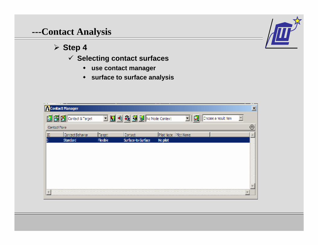
Step 4Selecting contact surfaces
use contact managersurface to surface analysis
---Contact Analysis
Dell Confidential
Client EngineeringClient Engineering
-
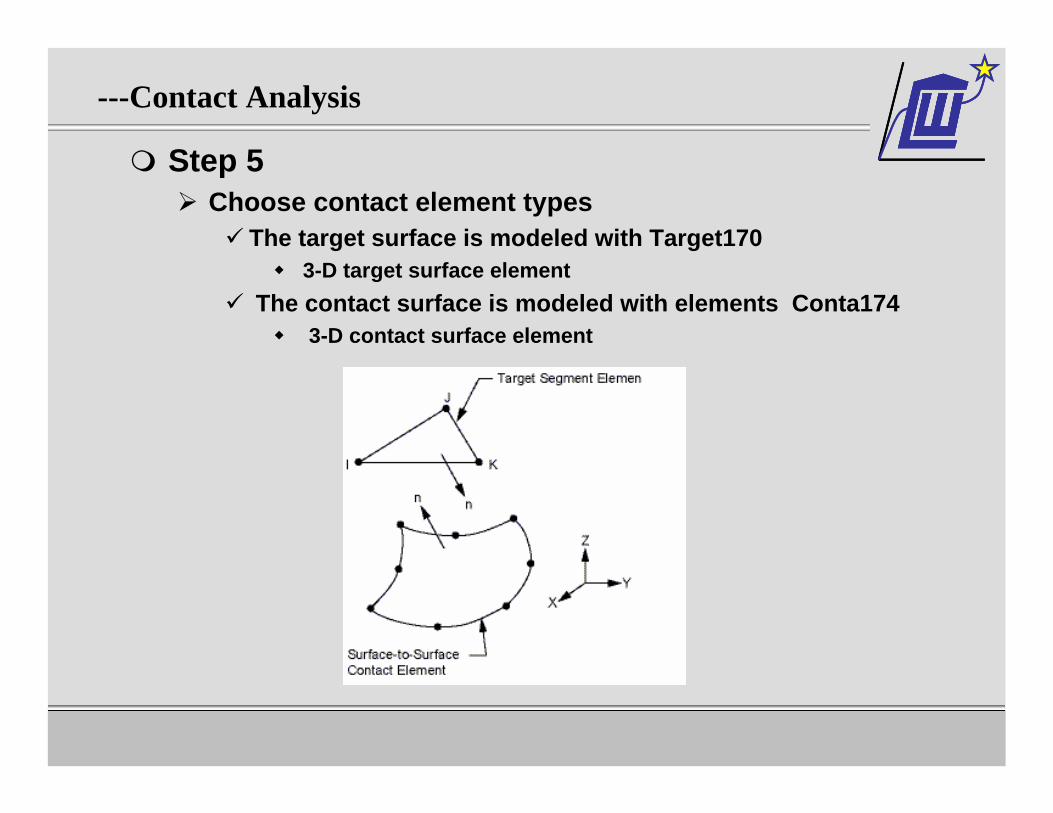
Step 5Choose contact element types
The target surface is modeled with Target170 3-D target surface element
The contact surface is modeled with elements Conta1743-D contact surface element
---Contact Analysis
Dell Confidential
Client EngineeringClient Engineering
-
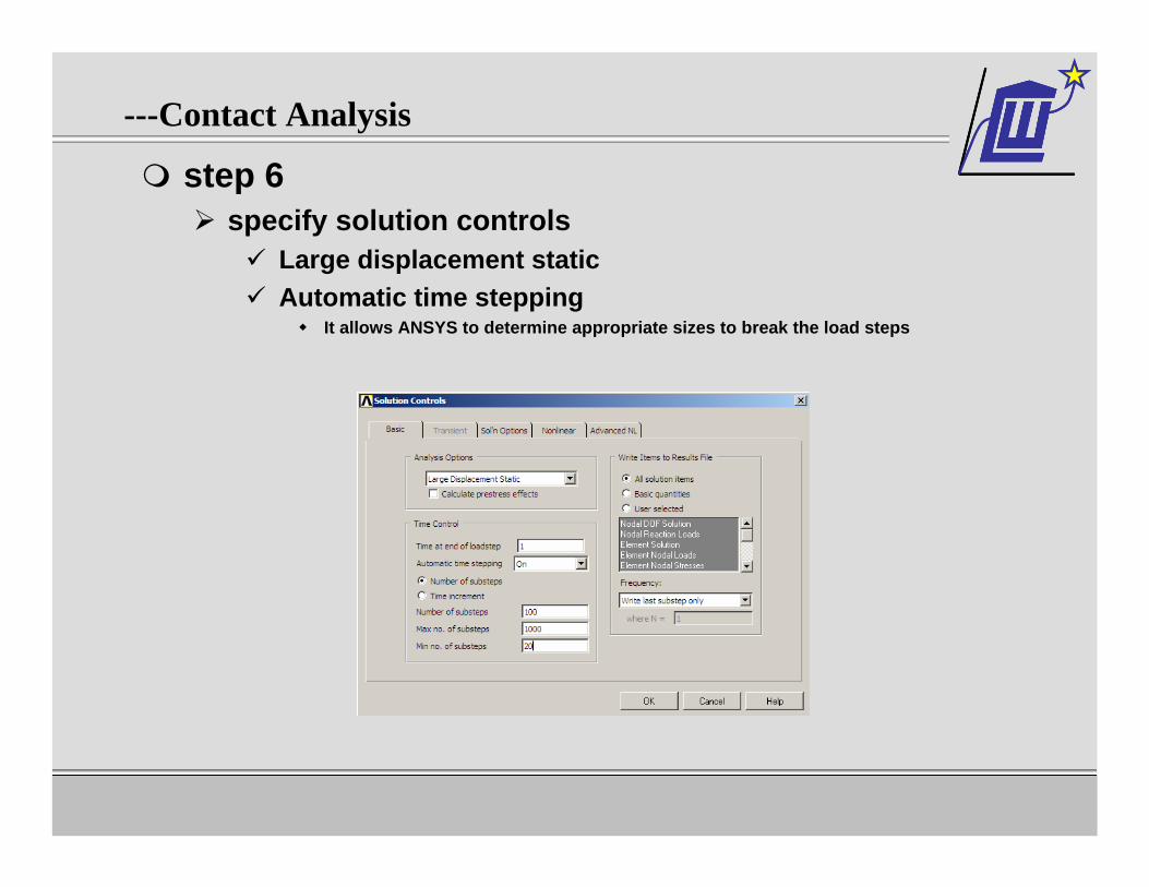
step 6specify solution controls
Large displacement staticAutomatic time stepping
It allows ANSYS to determine appropriate sizes to break the load steps
---Contact Analysis
Dell Confidential
Client EngineeringClient Engineering
-
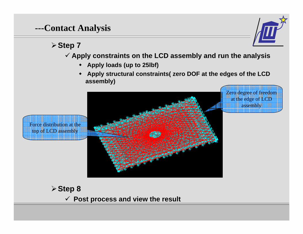
Step 7 Apply constraints on the LCD assembly and run the analysis
Apply loads (up to 25lbf)Apply structural constraints( zero DOF at the edges of the LCD assembly)
Step 8 Post process and view the result
Zero degree of freedom at the edge of LCD
assembly
Force distribution at the top of LCD assembly
---Contact Analysis
Dell Confidential
Client EngineeringClient Engineering
-
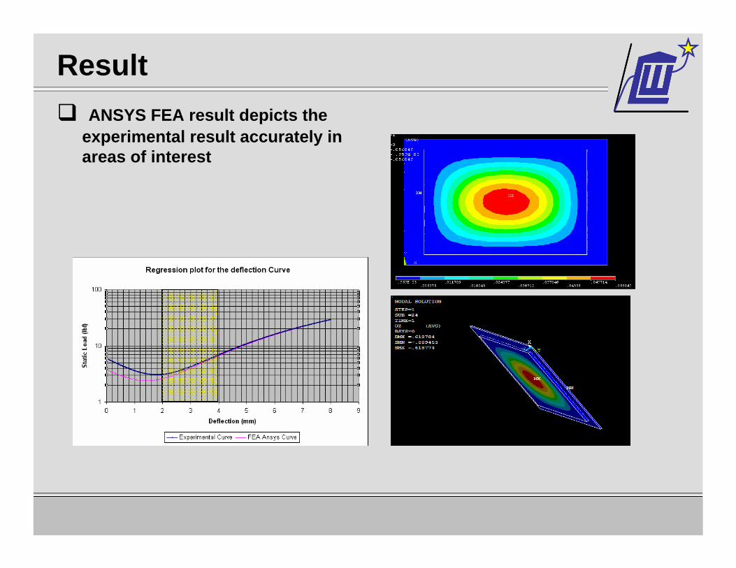
Result ANSYS FEA result depicts the
experimental result accurately in areas of interest

Dell Confidential
Client EngineeringClient Engineering
-
Result
Areas of deflection (>3.8043mm) on the LCD depicts T and P failure areas on the LCD panel

Dell Confidential
Client EngineeringClient Engineering
-
Result - contact stress

Dell Confidential
Client EngineeringClient Engineering
-
Result- contact stress
Areas of Higher contact stress (>4.89MPa) depicts the three types of failure

Dell Confidential
Client EngineeringClient Engineering
-
Solution specificationEngineering solutions will be based on the following parameters (sustaining)
Thickness of the magnesium panelThickness of the magnesium panel recommended for the market is 2mm; however this thickness can be changed to +0.5mm/-0.5mm. Due to product feature requirements the shape of the panel need not to be changed.
The Gap between the LCD and the PanelThis parameter can be changed to the desired level, or can be stuffed with material as long as it wouldn’t give an extra of 0.5lb in overall weight of the product.
The type of material to be used for the LCDThis parameter is very restricted, at this moment the magnesium can only be
substituted with BPL 1000 Plastic panel.
Dell Confidential
Client EngineeringClient Engineering
-
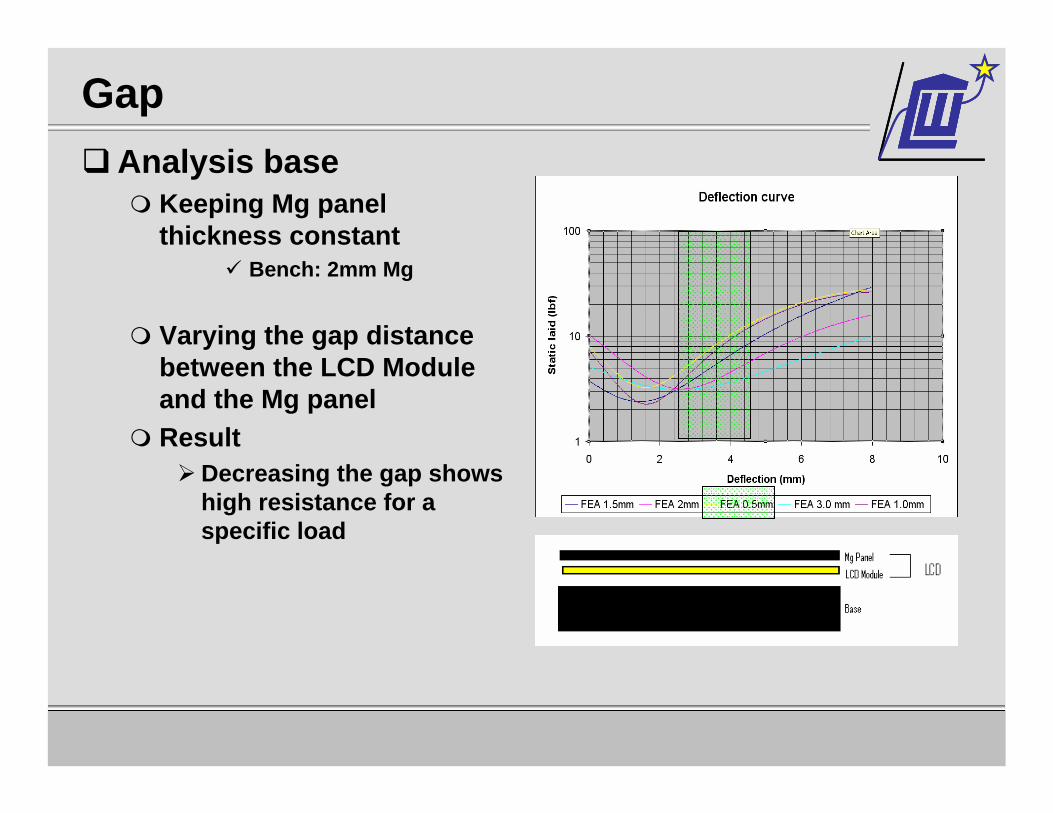
Gap Analysis base
Keeping Mg panel thickness constant
Bench: 2mm Mg
Varying the gap distance between the LCD Module and the Mg panelResult
Decreasing the gap shows high resistance for a specific load
Dell Confidential
Client EngineeringClient Engineering
-
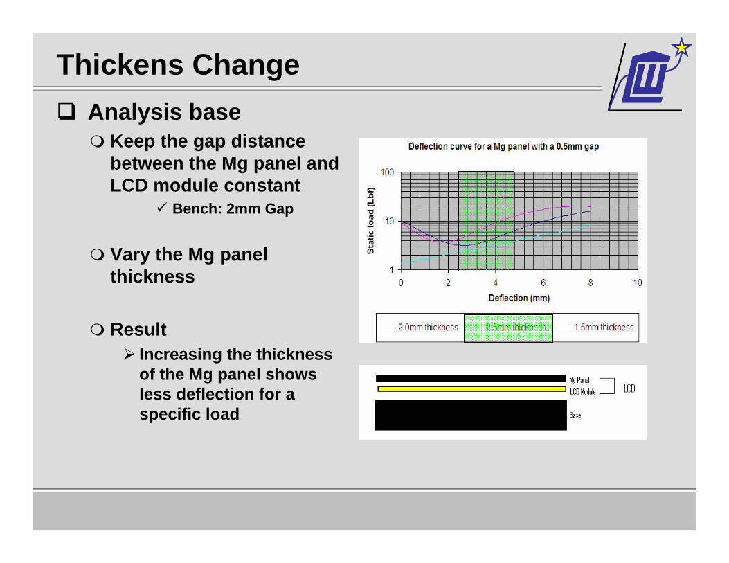
Thickens ChangeAnalysis base
Keep the gap distance between the Mg panel and LCD module constant
Bench: 2mm Gap
Vary the Mg panel thickness
ResultIncreasing the thickness of the Mg panel shows less deflection for a specific load

Dell Confidential
Client EngineeringClient Engineering
-
Changing material typeDue to product cosmetic and DFC issues changing
material type was not an applicable option
Dell Confidential
Client EngineeringClient Engineering
-
Conclusion
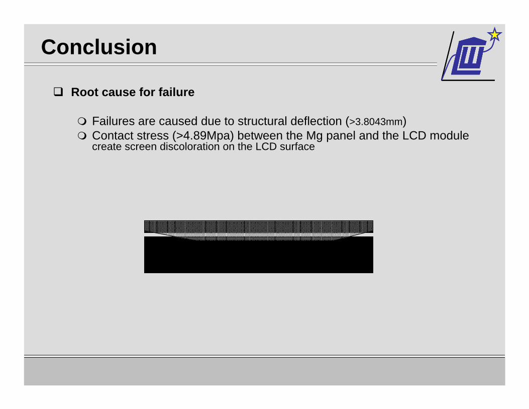
Root cause for failure
Failures are caused due to structural deflection (>3.8043mm) Contact stress (>4.89Mpa) between the Mg panel and the LCD module create screen discoloration on the LCD surface
Dell Confidential
Client EngineeringClient Engineering
-
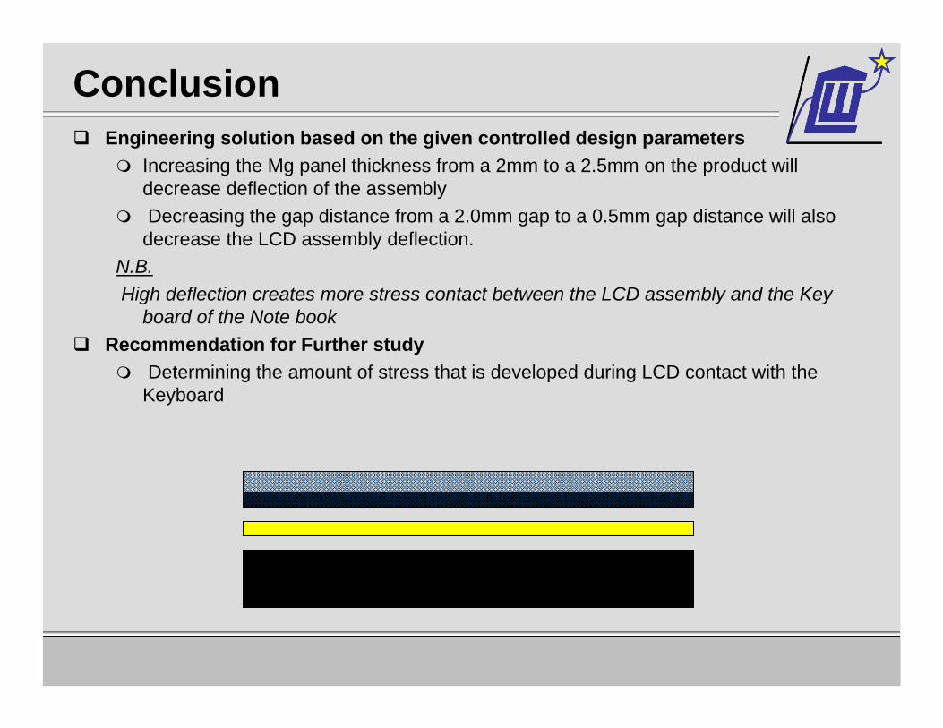
ConclusionEngineering solution based on the given controlled design parameters
Increasing the Mg panel thickness from a 2mm to a 2.5mm on the product will decrease deflection of the assembly Decreasing the gap distance from a 2.0mm gap to a 0.5mm gap distance will also decrease the LCD assembly deflection.
N.B.High deflection creates more stress contact between the LCD assembly and the Key
board of the Note book Recommendation for Further study
Determining the amount of stress that is developed during LCD contact with the Keyboard

Dell Confidential
Client EngineeringClient Engineering
-
Thank you