Embed Size (px)
Citation preview

Failure Analysis of a Cracked UH-1 Tailboom Former,
P/N 205-030-807-97
by Scott Grendahl, Benjamin Hardisky, and Russell Yocum
ARL-TR-3828 June 2006
prepared by
Scott Grendahl U.S. Army Research Laboratory
Weapons and Materials Research Directorate Aberdeen Proving Ground, MD 21005
Benjamin Hardisky and Russell Yocum
U.S. Army Aberdeen Test Center Physical Test Unit
Aberdeen Proving Ground, MD 21005
for
U.S. Army Aviation and Missile Command Huntsville, AL 35899
Approved for public release; distribution is unlimited.

NOTICES
Disclaimers The findings in this report are not to be construed as an official Department of the Army position unless so designated by other authorized documents. Citation of manufacturer’s or trade names does not constitute an official endorsement or approval of the use thereof. Destroy this report when it is no longer needed. Do not return it to the originator.
Army Research Laboratory Aberdeen Proving Ground, MD 21005-5069
ARL-TR-3828 June 2006
Failure Analysis of a Cracked UH-1 Tailboom Former, P/N 205-030-807-97
prepared by
Scott Grendahl U.S. Army Research Laboratory
Weapons and Materials Research Directorate Aberdeen Proving Ground, MD 21005
Benjamin Hardisky and Russell Yocum
U.S. Army Aberdeen Test Center Physical Test Unit
Aberdeen Proving Ground, MD 21005
for
U.S. Army Aviation and Missile Command Huntsville, AL 35899
Approved for public release; distribution is unlimited.
ii
REPORT DOCUMENTATION PAGE Form Approved OMB No. 0704-0188
Public reporting burden for this collection of information is estimated to average 1 hour per response, including the time for reviewing instructions, searching existing data sources, gathering and maintaining the data needed, and completing and reviewing the collection information. Send comments regarding this burden estimate or any other aspect of this collection of information, including suggestions for reducing the burden, to Department of Defense, Washington Headquarters Services, Directorate for Information Operations and Reports (0704-0188), 1215 Jefferson Davis Highway, Suite 1204, Arlington, VA 22202-4302. Respondents should be aware that notwithstanding any other provision of law, no person shall be subject to any penalty for failing to comply with a collection of information if it does not display a currently valid OMB control number. PLEASE DO NOT RETURN YOUR FORM TO THE ABOVE ADDRESS. 1. REPORT DATE (DD-MM-YYYY)
June 2006 2. REPORT TYPE
Final 3. DATES COVERED (From - To)
1 January 2005–31 August 2005 5a. CONTRACT NUMBER
5b. GRANT NUMBER
4. TITLE AND SUBTITLE
Failure Analysis of a Cracked UH-1 Tailboom Former, P/N 205-030-807-97
5c. PROGRAM ELEMENT NUMBER
5d. PROJECT NUMBER
M042-489Y31 5e. TASK NUMBER
6. AUTHOR(S)
Scott Grendahl, Benjamin Hardisky,* and Russell Yocum*
5f. WORK UNIT NUMBER
7. PERFORMING ORGANIZATION NAME(S) AND ADDRESS(ES)
U.S. Army Research Laboratory U.S. Army Aberdeen Test Center ATTN: AMSRD-ARL-WM-MC Physical Test Unit Aberdeen Proving Ground, MD Aberdeen Proving Ground, MD 21005-5069 21005
8. PERFORMING ORGANIZATION REPORT NUMBER
ARL-TR-3828
10. SPONSOR/MONITOR'S ACRONYM(S)
9. SPONSORING/MONITORING AGENCY NAME(S) AND ADDRESS(ES)
U.S. Army Aviation and Missile Command Huntsville, AL 35899 11. SPONSOR/MONITOR'S REPORT
NUMBER(S)
12. DISTRIBUTION/AVAILABILITY STATEMENT
Approved for public release; distribution is unlimited. 13. SUPPLEMENTARY NOTES *U.S. Army Aberdeen Test Center, Physical Test Unit, Aberdeen Proving Ground, MD 21005-5069
14. ABSTRACT
The U.S. Army Aviation and Missile Command sent the U.S. Army Research Laboratory Weapons and Materials Research Directorate a UH-1 tailboom former (P/N 201030-807-97) from the U.S. Army Kwajalein Atoll Facility (USAKA) in the Marshall Islands for investigation. The component was being investigated due to the presence of cracks observed near bolt hole locations on the part. This component was quality deficient report exhibit number M24H90327. The material utilized to manufacture the former was specified to be clad 2024-T4 aluminum alloy sheet in accordance with QQ-A-362. It was superseded by QQ-A-250/5B, which was subsequently cancelled, and superseded by the current specification for clad 2024-T4 aluminum sheet, SAE-AMS-QQ-A-250-5. The part was characterized through nondestructive inspection, chemical analysis, optical microscopy, scanning electron microscopy, and mechanical testing.
15. SUBJECT TERMS
failure analysis, 9310 steel, fatigue, helicopter gear
16. SECURITY CLASSIFICATION OF: 19a. NAME OF RESPONSIBLE PERSON Scott Grendahl
a. REPORT UNCLASSIFIED
b. ABSTRACT UNCLASSIFIED
c. THIS PAGE UNCLASSIFIED
17. LIMITATION OF ABSTRACT
UL
18. NUMBER OF PAGES
30
19b. TELEPHONE NUMBER (Include area code) 410-306-0819
Standard Form 298 (Rev. 8/98) Prescribed by ANSI Std. Z39.18

iii
Contents
List of Figures iv
List of Tables iv
1. Introduction 1
2. Fluorescent Penetrant Inspection and Eddy Current Testing 2
3. Visual Inspection and Light Optical Microscopy 3
4. Scanning Electron Microscopy (SEM) 6
5. Metallography 12
6. Chemical Analysis 15
7. Hardness and Conductivity Testing 15
8. Coating System 15
9. Failure Scenario 16
10. Conclusions 19
Distribution List 20

iv
List of Figures
Figure 1. As-received component UH-1 tailboom former..............................................................1 Figure 2. Fluorescent indication of the crack on side A. ................................................................2 Figure 3. Fluorescent indication of the crack on side B. ................................................................3 Figure 4. One half of the fracture surface of the crack on side A...................................................4 Figure 5. Fractograph of one half of the fracture surface. ..............................................................4 Figure 6. Fractograph of the corrosion initiation site on side A. ....................................................5 Figure 7. Fractograph of the corrosion initiation site on side A at 45°...........................................5 Figure 8. Fractograph of the corrosion initiation site on side B. ....................................................6 Figure 9. Fractograph of the corrosion initiation site on side B at 45°...........................................7 Figure 10. Fractograph of the origin near the center of the crack...................................................7 Figure 11. SEM fractograph of the whole crack on one fracture half. ...........................................8 Figure 12. Transgranular fatigue to ductile overload transition zone. ............................................8 Figure 13. Fractograph of the origin area on side A. ......................................................................9 Figure 14. Fractograph of the origin area at 45° on side A. ...........................................................9 Figure 15. Higher magnification image of the large corrosion pit on side A. ..............................10 Figure 16. Fractograph of the origin area on side B. ....................................................................10 Figure 17. Fractograph of the origin area at 45° on side B...........................................................11 Figure 18. SEM micrograph of the center fatigue initiation site. .................................................11 Figure 19. SEM micrograph of the center fatigue initiation site at 45°........................................12 Figure 20. Longitudinal cross section showing the cladding of the 2024-T4 alloy......................13 Figure 21. Transverse cross section showing the cladding of the 2024-T4 alloy.........................13 Figure 22. Longitudinal microstructure of the 2024-T4 alloy. .....................................................14 Figure 23. Transverse microstructure of the 2024-T4 alloy. ........................................................14 Figure 24. Former compared with a golden yellow chromate conversion coated component. ....17 Figure 25. Exterior surface of the tailboom former coated with MIL-P-23377. ..........................17 Figure 26. Corrosion pitting band near edge of crevice compression line. ..................................18 Figure 27. Pits adjacent to the edge of the fracture.......................................................................18 Figure 28. Pitting and corrosion product along the edge of compression line. ............................19
v
List of Tables
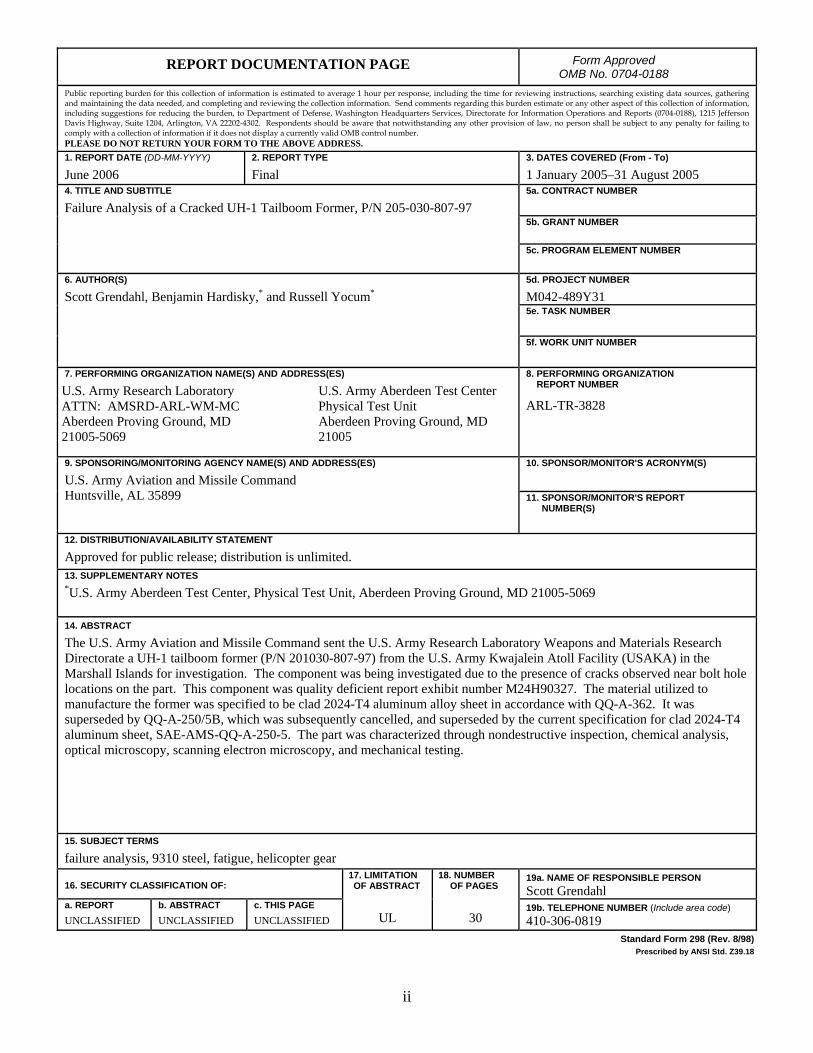
Table 1. Chemical composition of the tailboom former, weight percent. ....................................15

vi
INTENTIONALLY LEFT BLANK.
1
1. Introduction
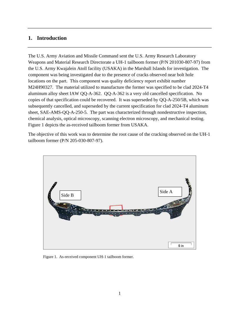
The U.S. Army Aviation and Missile Command sent the U.S. Army Research Laboratory Weapons and Material Research Directorate a UH-1 tailboom former (P/N 201030-807-97) from the U.S. Army Kwajalein Atoll facility (USAKA) in the Marshall Islands for investigation. The component was being investigated due to the presence of cracks observed near bolt hole locations on the part. This component was quality deficiency report exhibit number M24H90327. The material utilized to manufacture the former was specified to be clad 2024-T4 aluminum alloy sheet IAW QQ-A-362. QQ-A-362 is a very old cancelled specification. No copies of that specification could be recovered. It was superseded by QQ-A-250/5B, which was subsequently cancelled, and superseded by the current specification for clad 2024-T4 aluminum sheet, SAE-AMS-QQ-A-250-5. The part was characterized through nondestructive inspection, chemical analysis, optical microscopy, scanning electron microscopy, and mechanical testing. Figure 1 depicts the as-received tailboom former from USAKA.
The objective of this work was to determine the root cause of the cracking observed on the UH-1 tailboom former (P/N 205-030-807-97).
Figure 1. As-received component UH-1 tailboom former.
Side A Side B
2
2. Fluorescent Penetrant Inspection and Eddy Current Testing
The penetrant materials included ZL-37 post emulsifiable hydrophilic penetrant (sensitivity level 4), ZR-10B remover (slow acting), and ZP-9F developer. This inspection was performed in accordance with MIL-STD-271F(SH),1 MIL-STD-6866B,2 and ASTM E-165.3 Penetrant inspection dwell times were doubled, the emulsifier times were reduced by 25%, and the developer dwell time was increased to 12 min to increase the possibility of detecting extremely tight flaws. The eddy current inspection utilized an Automation Industries 6300 eddy current unit, a 500-kHz shielded absolute pancake probe, 1/8-in diameter pencil, 500-kHz shielded absolute pancake probe 1/4-in diameter (spring loaded), and a Zetek aluminum electric discharge machine block.
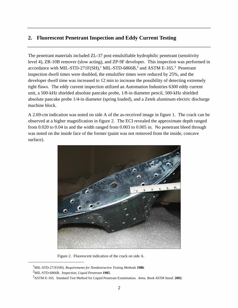
A 2.69-cm indication was noted on side A of the as-received image in figure 1. The crack can be observed at a higher magnification in figure 2. The ECI revealed the approximate depth ranged from 0.020 to 0.04 in and the width ranged from 0.003 to 0.005 in. No penetrant bleed through was noted on the inside face of the former (paint was not removed from the inside, concave surface).
Figure 2. Fluorescent indication of the crack on side A.
1MIL-STD-271F(SH). Requirements for Nondestructive Testing Methods 1986. 2MIL-STD-6866B. Inspection, Liquid Penetrant 1985. 3ASTM E-165. Standard Test Method for Liquid Penetrant Examination. Annu. Book ASTM Stand. 2002.
3
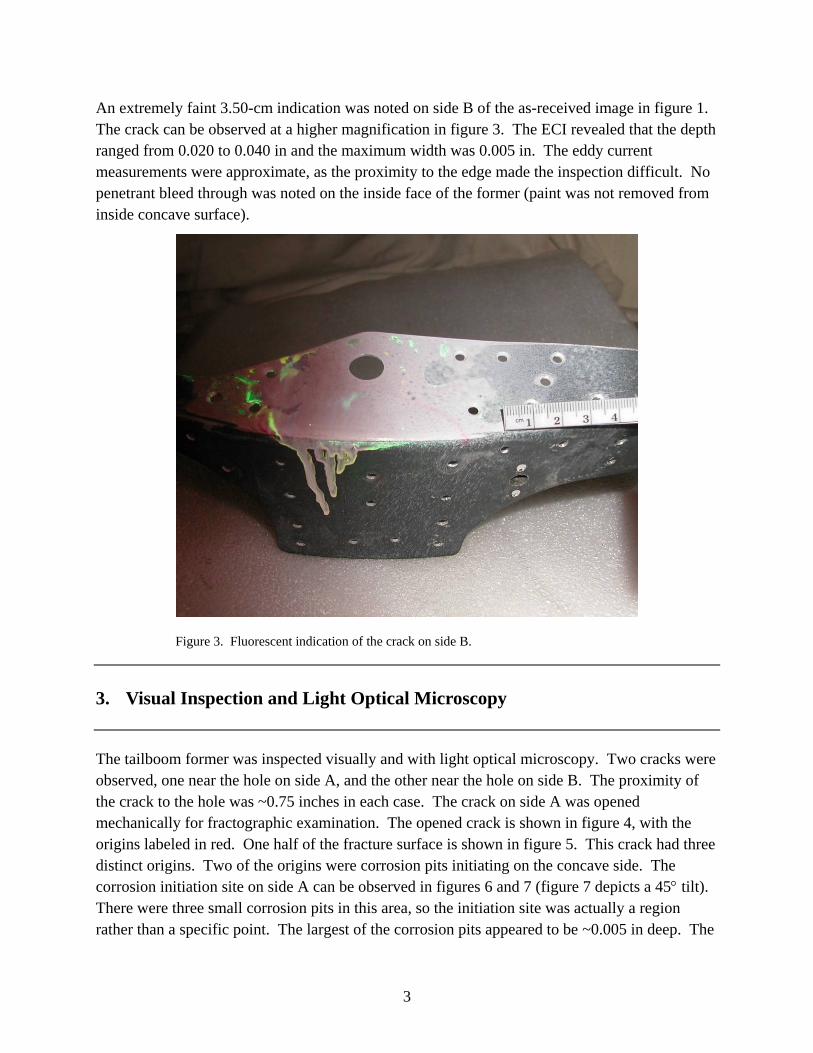
An extremely faint 3.50-cm indication was noted on side B of the as-received image in figure 1. The crack can be observed at a higher magnification in figure 3. The ECI revealed that the depth ranged from 0.020 to 0.040 in and the maximum width was 0.005 in. The eddy current measurements were approximate, as the proximity to the edge made the inspection difficult. No penetrant bleed through was noted on the inside face of the former (paint was not removed from inside concave surface).
Figure 3. Fluorescent indication of the crack on side B.
3. Visual Inspection and Light Optical Microscopy
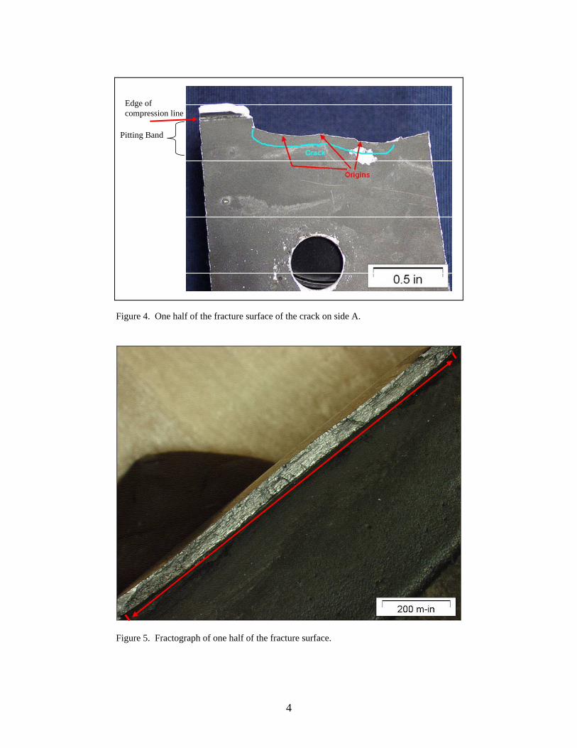
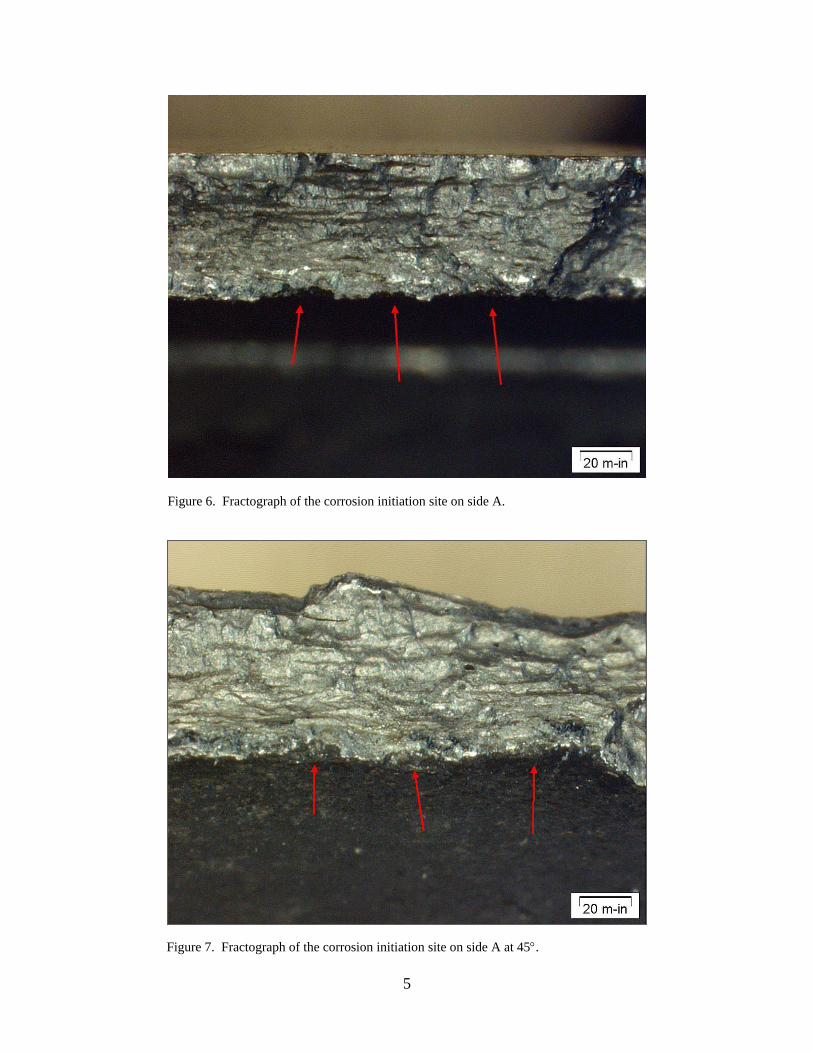
The tailboom former was inspected visually and with light optical microscopy. Two cracks were observed, one near the hole on side A, and the other near the hole on side B. The proximity of the crack to the hole was ~0.75 inches in each case. The crack on side A was opened mechanically for fractographic examination. The opened crack is shown in figure 4, with the origins labeled in red. One half of the fracture surface is shown in figure 5. This crack had three distinct origins. Two of the origins were corrosion pits initiating on the concave side. The corrosion initiation site on side A can be observed in figures 6 and 7 (figure 7 depicts a 45° tilt). There were three small corrosion pits in this area, so the initiation site was actually a region rather than a specific point. The largest of the corrosion pits appeared to be ~0.005 in deep. The
4
Pitting Band
Edge of compression line
Figure 4. One half of the fracture surface of the crack on side A.
Figure 5. Fractograph of one half of the fracture surface.
5
Figure 6. Fractograph of the corrosion initiation site on side A.
Figure 7. Fractograph of the corrosion initiation site on side A at 45°.

6
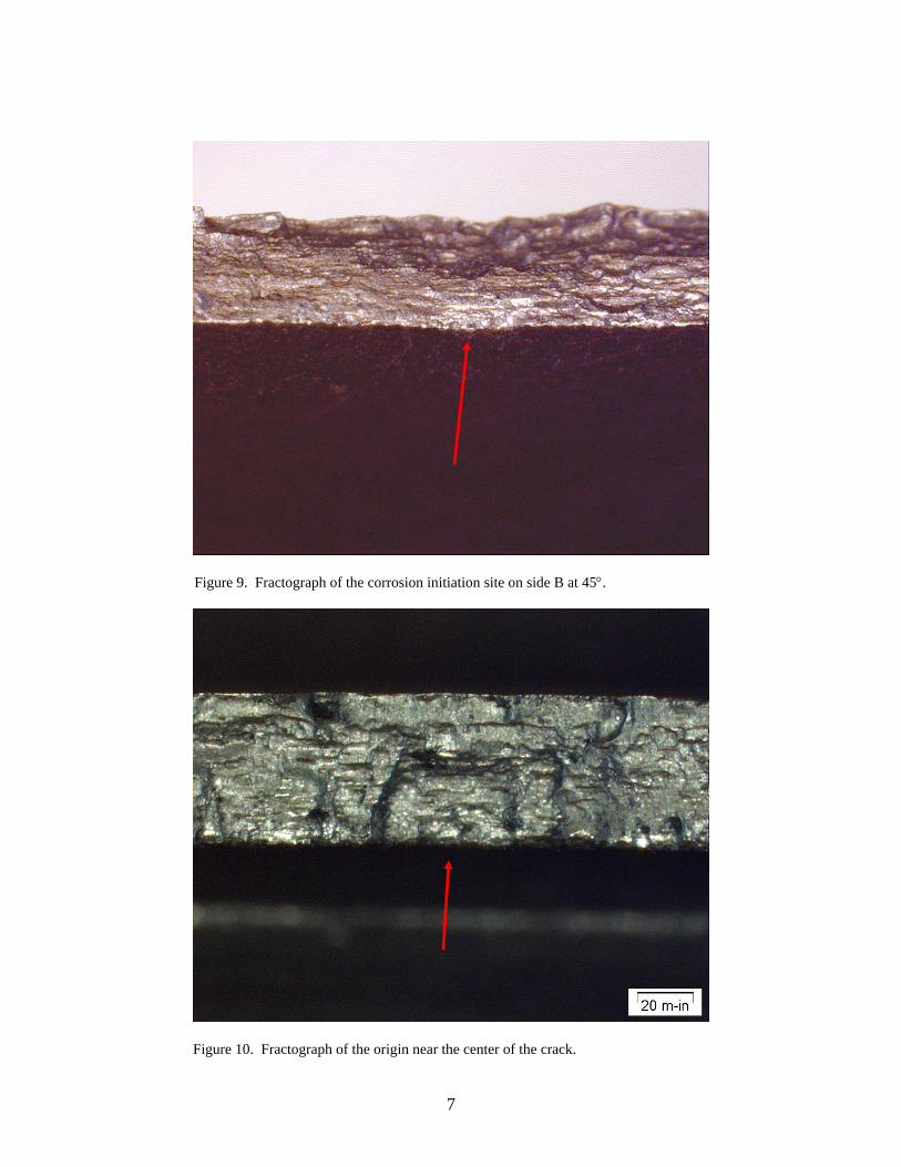
corrosion initiation site on side B can be observed in figures 8 and 9 (figure 9 depicts a 45° tilt). Crack arrest lines (beach marks) and chevron patterns were observable on the fracture surface near these origins. The third origin was fatigue initiated at a surface imperfection unrelated to corrosion, but also on the concave side of the component. This initiation site can be observed in figure 10. The crack progression spread out symmetrically from these three points to form a final crack length of 1.25 in, as observed in figure 5. It was apparent that the cracks joined together and propagated entirely through the 0.050-in thickness of the tailboom former.
4. Scanning Electron Microscopy (SEM)
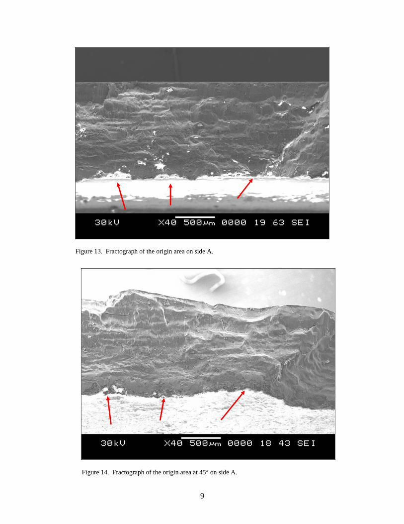
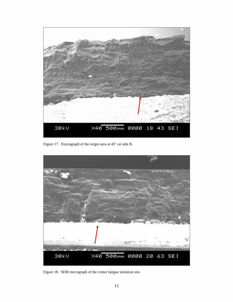
SEM, utilizing a JEOL-JSM 6460-LV, was performed to investigate the fracture surfaces in greater detail. The fracture surface of the opened crack is depicted in the electron fractograph in figure 11. The total crack length measured 1.25 in. At closer inspection, evidence of cyclic fatigue crack propagation was present (figure 12). Fatigue progression lines can easily be observed (this is the transition region at the end of the crack between transgranular fracture and ductile overload). The fracture morphology was transgranular throughout the cracked region. The origin area on side A is depicted in figure 13 and at 45° in figure 14. A higher magnification image of the large corrosion pit on side A is shown in figure 15. The origin area on side B is depicted in figure 16 and at 45° in figure 17. The third initiation site can be observed in figures 18 and 19. All the origins were on the concave side of the part.
Figure 8. Fractograph of the corrosion initiation site on side B.
7
Figure 9. Fractograph of the corrosion initiation site on side B at 45°.
Figure 10. Fractograph of the origin near the center of the crack.

8
Figure 11. SEM fractograph of the whole crack on one fracture half.
Figure 12. Transgranular fatigue to ductile overload transition zone.
9
Figure 13. Fractograph of the origin area on side A.
Figure 14. Fractograph of the origin area at 45° on side A.

10
Figure 15. Higher magnification image of the large corrosion pit on side A.
Figure 16. Fractograph of the origin area on side B.
11
Figure 17. Fractograph of the origin area at 45° on side B.
Figure 18. SEM micrograph of the center fatigue initiation site.

12
Figure 19. SEM micrograph of the center fatigue initiation site at 45°.
5. Metallography
Longitudinal and transverse (to the sheet rolling direction) cross sections were metallographically prepared. The sections were ground and polished through 0.025-µm noncolloidal silica. Subsequently, the specimen was etched with Keller’s reagent. The microstructure of the tailboom former material was found to be consistent with clad 2024-T4 aluminum alloy. The cladding can be observed in the longitudinal and transverse direction in figures 20 and 21. The precipitates were determined to be CuMgAl2, Cu2MnAl20, and Cu2FeAl7. The smaller precipitates formed during the annealing process, while the larger precipitates were undissolved from the solutionizing treatment. No abnormalities were observed. Representative photos of both the longitudinal and transverse cross sections are observable in figures 22 and 23, respectively.

13
Mil-P-23377
Cladding
2024-T4 Substrate
Figure 20. Longitudinal cross section showing the cladding of the 2024-T4 alloy.
Mil-P-23377
Cladding
2024-T4 Substrate
Figure 21. Transverse cross section showing the cladding of the 2024-T4 alloy.

14
Figure 22. Longitudinal microstructure of the 2024-T4 alloy.
Figure 23. Transverse microstructure of the 2024-T4 alloy.

15
6. Chemical Analysis
The chemical composition of the tailboom former was analyzed with direct current plasma emission spectroscopy (DC plasma). The sample was sectioned from an area adjacent to the bolt hole where the cracks were located. The results are listed, along with the chemical composition requirements as required by the engineering drawing in table 1. The chemical constituency of the component compared favorably with the specified requirements in SAE-AMS-QQ-A-250-5.
Table 1. Chemical composition of the tailboom former, weight percent.
Element Former (%)
SAE-AMS-QQ-A-250-5 (%)
Iron 0.24 0.50 max Manganese 0.49 0.30–0.90 Silicon 0.090 0.50 max Copper 4.34 3.8–4.9 Zinc 0.089 0.25 max Magnesium 1.41 1.20–1.80 Chromium 0.016 0.10 max Titanium 0.025 0.15 max Gallium 0.011 0.05 max Vanadium 0.030 0.05 max Nickel 0.012 0.05 max Aluminum Remainder Remainder
7. Hardness and Conductivity Testing
Hardness and conductivity measurements were made near the cracked areas on the outside surface of the tailboom former. The hardness of the component measured 45.0 HRA, (measured 153 HV) and the conductivity measured 31.0% IACS. These values compared favorably with typical clad aluminum 2024-T4 alloy.
8. Coating System
Since the apparent cause of failure of this component was fatigue initiated at corrosion pits, the coating system itself was investigated. The coating system for the tailboom former was required to be chromate conversion coating (golden yellow to brown) with one coat of MIL-P-23377, type II primer (applied per MIL-C-53072) in accordance with the Spares TDP 205-030-807 and Bell Helicopter Specification BPS 4182. The MIL-P-23377 was chemically removed so the chromate

16
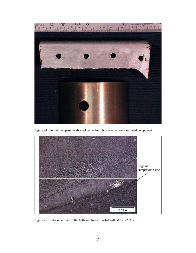
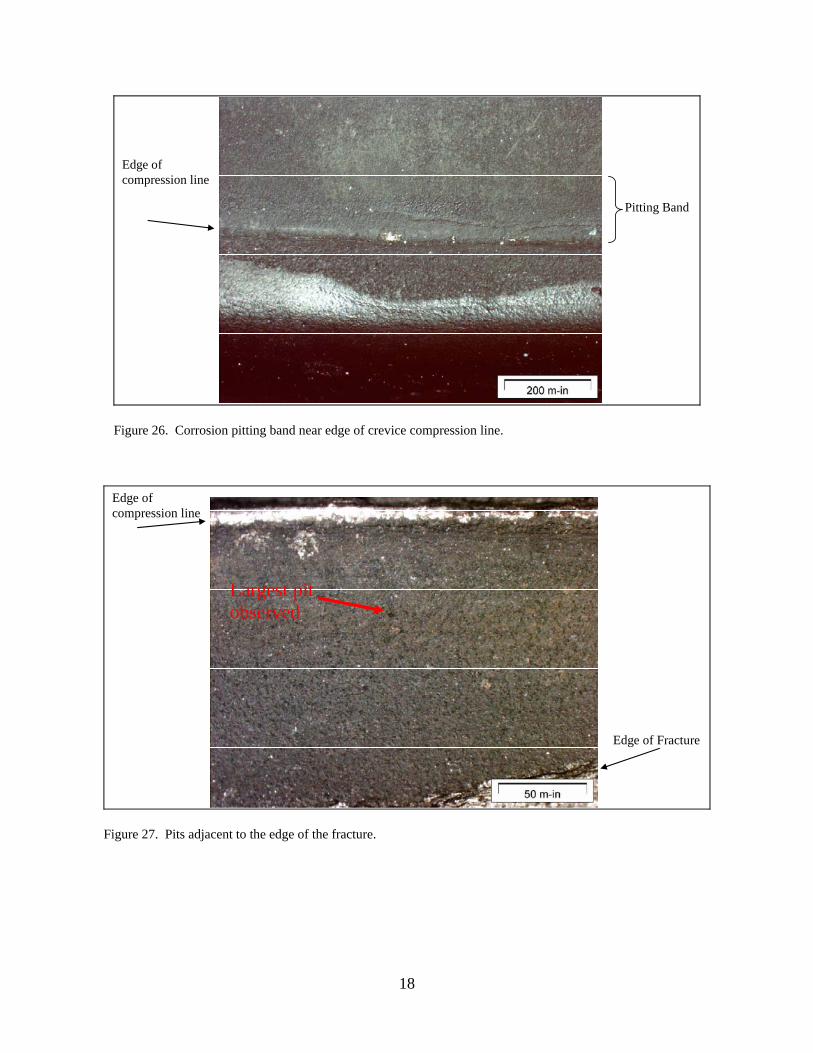
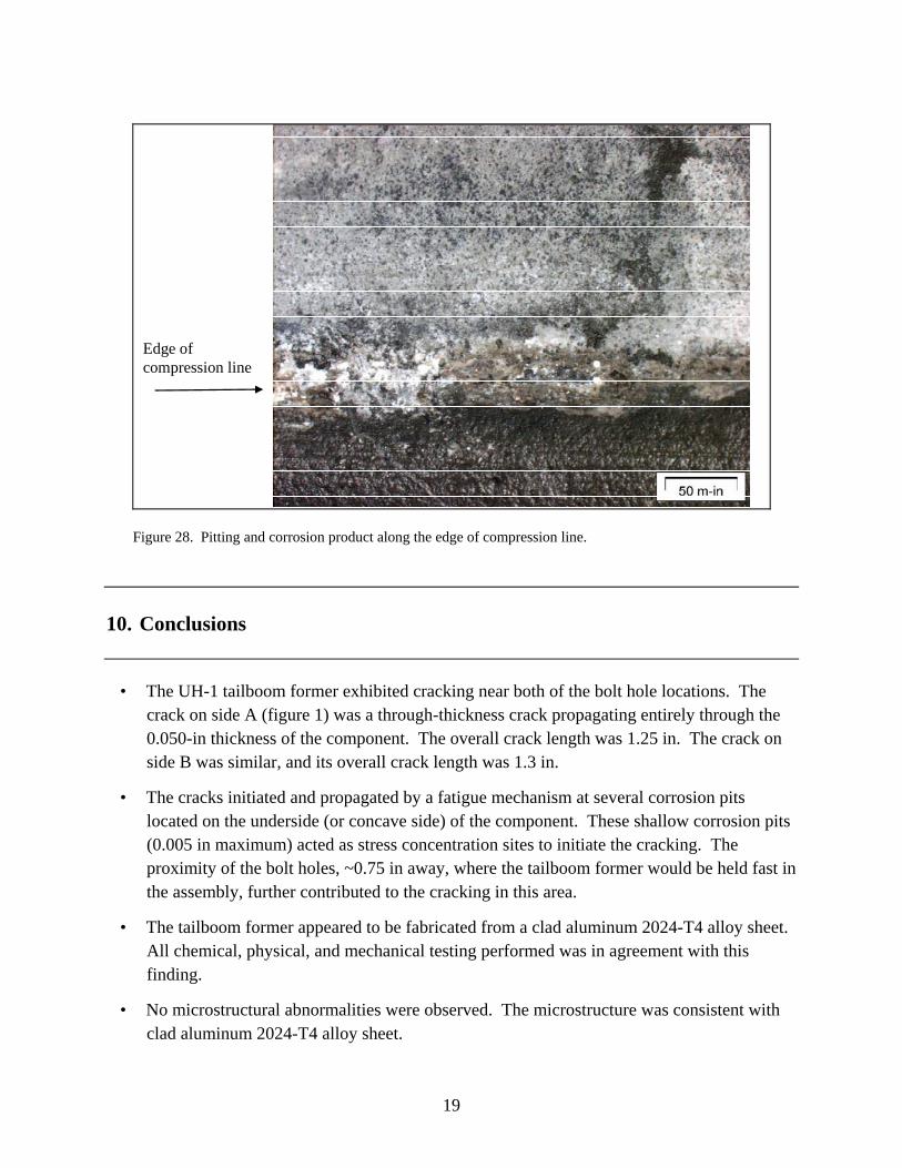
conversion coating could be visually inspected. There was no visible golden yellow to brown chromate conversion under the primer. Two important notes accompany this fact. The first is contingent upon the age of the component; the golden yellow to brown color can fade over time as it is meant to be sacrificial. The second is simply that a clear coat chromate conversion treatment (not in accordance with the specification) would not be visible. So the case exists that either the chromate coating has degraded over time or it was never applied correctly when the part was manufactured. The primer itself contains chromates so chemical analysis of the surface proved futile. A comparison of the exterior surface of the former with the primer removed vs. a golden yellow chromate conversion coated component is presented in figure 24. The typical exterior surface of the primed coating can be observed in figure 25. This figure also includes the crack prior to it being opened. The coating system can be observed in cross sections in figures 20 and 21. The primer measured ~0.001 in thick and was within the 0.0008–0.0012-in requirement. The chromate chemical conversion coating is usually just a dip process, and while it leaves a chemical signature, it cannot be observed in a cross section. The MIL-P-23377 coating was intact, relatively undamaged, and appeared uniform and consistent in application. The tailboom former mates with a larger section of a tailboom, and the cracks were within this compressed section forming a crevice. The primer was not marred or worn, just uniformly compressed from the assembly. The edge of this compression can be observed in figure 25. There appeared to be a band of corrosion pitting of various sizes and depths extending to ~0.150 in from the edge of the crevice formed by the assembly. This band can be observed in figure 26. Examples of the corrosion pits adjacent to the fracture are depicted in figures 27 and 28. The largest pit observed was estimated to be 0.004 inches deep and 0.005 inches in diameter. It is important to note that the pits in figure 27 were fully and completely painted over; the paint conformed to the pit surface topography. Therefore, the pits did not form under the paint; they existed immediately prior to the last painting. They either formed during service within the crevice or during overhaul processing. They were not found all about the exterior surfaces, so it is more likely that they formed within the crevice during service.
9. Failure Scenario
The tailboom former failed by a fatigue mechanism initiated at corrosion pits. These pits likely developed over time either from damage induced during overhaul or within the natural crevice formed by the tailboom former and its mating component in the assembly. Pits were observed both with paint covering them and inactive, and recently active and corroding. It is likely that some of the pitting corrosion was missed during overhaul and paint was reapplied over them.
17
Figure 24. Former compared with a golden yellow chromate conversion coated component.
Edge of compression line
Figure 25. Exterior surface of the tailboom former coated with MIL-P-23377.
18
Edge of compression line
Pitting Band
Figure 26. Corrosion pitting band near edge of crevice compression line.
Edge of compression line
Edge of Fracture
Largest pit observed
Figure 27. Pits adjacent to the edge of the fracture.
19
Edge of compression line
Figure 28. Pitting and corrosion product along the edge of compression line.
10. Conclusions
• The UH-1 tailboom former exhibited cracking near both of the bolt hole locations. The crack on side A (figure 1) was a through-thickness crack propagating entirely through the 0.050-in thickness of the component. The overall crack length was 1.25 in. The crack on side B was similar, and its overall crack length was 1.3 in.
• The cracks initiated and propagated by a fatigue mechanism at several corrosion pits located on the underside (or concave side) of the component. These shallow corrosion pits (0.005 in maximum) acted as stress concentration sites to initiate the cracking. The proximity of the bolt holes, ~0.75 in away, where the tailboom former would be held fast in the assembly, further contributed to the cracking in this area.
• The tailboom former appeared to be fabricated from a clad aluminum 2024-T4 alloy sheet. All chemical, physical, and mechanical testing performed was in agreement with this finding.
• No microstructural abnormalities were observed. The microstructure was consistent with clad aluminum 2024-T4 alloy sheet.

NO. OF COPIES ORGANIZATION
20
1 DEFENSE TECHNICAL (PDF INFORMATION CTR ONLY) DTIC OCA 8725 JOHN J KINGMAN RD STE 0944 FORT BELVOIR VA 22060-6218 1 US ARMY RSRCH DEV & ENGRG CMD SYSTEMS OF SYSTEMS INTEGRATION AMSRD SS T 6000 6TH ST STE 100 FORT BELVOIR VA 22060-5608 1 INST FOR ADVNCD TCHNLGY THE UNIV OF TEXAS AT AUSTIN 3925 W BRAKER LN AUSTIN TX 78759-5316 1 DIRECTOR US ARMY RESEARCH LAB IMNE ALC IMS 2800 POWDER MILL RD ADELPHI MD 20783-1197 3 DIRECTOR US ARMY RESEARCH LAB AMSRD ARL CI OK TL 2800 POWDER MILL RD ADELPHI MD 20783-1197
ABERDEEN PROVING GROUND 1 DIR USARL AMSRD ARL CI OK TP (BLDG 4600)

NO. OF COPIES ORGANIZATION
21
ABERDEEN PROVING GROUND 10 USARL AMSRD ARL WM MC S GRENDAHL

22
INTENTIONALLY LEFT BLANK.


![Legends of Orange County: The Art of Hal McIntosh › omeka › files › original › ... · Uh, and, uh, Siesta Key[, Florida] [inaudible]. Parke . Mmhmm. McIntosh . And, uh, uh,](https://img.dokumen.tips/doc/110x75/5f1d881683f7476ca33e016c/legends-of-orange-county-the-art-of-hal-mcintosh-a-omeka-a-files-a-original.jpg)