Embed Size (px)
Citation preview

kapitel 2
Fail-Safe Communications
via Standard Fieldbuses

2.1 PROFIsafe
2.2 AS-Interface Safety at Work

Fail-safe communications usingstandard fieldbuses with PROFIsafeand AS-Interface Safety at Work
Selecting the correct installation tech-nology is an important step in reducingcosts. In standard technology, themove to distributed concepts and theuse of modern fieldbuses have alreadyresulted in significant cost savings.In the future, further cost savings willbe achieved by transferring additionalsafety-related signals along existingstandard fieldbuses.
Overall system with integratedsafety
With the “Safety Integrated” concept,for the first time, safety-related signalscan be combined with the standardautomation data of a system.ThePROFIBUS and AS-Interface fieldbussystems are used to form a transpar-ent harmonized overall system.
By placing safety-related communica-tions on these proven standard field-buses, plant and system engineers canwork more cost-effectively in the stan-dard automation environment as wellas in safety technology as they canuse the same engineering tools andmethods. Contrary to concepts whichuse special buses to transfer safety-related data, in this case, there is datatransparency between the standardand safety-related part of an overallplant or system without requiring anyadditional interfaces.
2/2 Safety Integrated Application Manual Siemens AG
Fail-Safe Communications using Standard Fieldbuses

Fig. 2/1 The basic principle of “Safety Integrated”:A unified automation system with integrated safety functions
Safety Integrated Application Manual Siemens AG 2/3
222
PROCESS FIELD BUS
DP/PA link
DP/AS-i link
• Light curtain• EMERGENCY STOP• Protective door monitoring
• SIMATIC PLC• Visualization• PCS 7-process control systems
Standard and safety-related systems inprocess engineering
PROFIBUS-PA
PROFIBUS-DP
• ET 200• Fail-safe SIMATIC• SINUMERIK/SIMODRIVE
• SIRIUS• Operator panel• BERO
• AS-Interface
Standard
Safety-relatedtechnologySafety Integratedwith AS-Interfacecoupling
Standardsystems
Safety-relatedtechnologySafety Integratedwith PROFIBUScoupling
AS-Interface

Safety-related communications viaPROFIBUS-DP using PROFIsafe
The PROFIBUS User Organization(PNO) published, in the Spring of 1999,Directives for safety-related communi-cations on Standard PROFIBUS underthe PROFIsafe trademark.This was theresult of a working group and has alsobeen acknowledged by the BIA [Ger-man Trade Association] and the TÜV[German Inspectorate] in the form ofpositive reports.
From the very start, the goal of theworking group was to involve as manypossible partners in defining andgenerating a solution and to make theresult available in an open form. Inaddition to manufacturers of safetysystems, more than 25 well-knowndomestic and international manufactur-ers of safety-related sensors and actu-ators, machine tool companies, endusers and universities are represented.Intermediate and final results arecontinually harmonized with the TÜV[German Inspectorate] and the BIA.The Verein Deutscher Werkzeug-maschinenfirmen (VDW) [Associationof German Machine Tool Manufactur-ers], who influenced the developmentof safety-related technology in theDESINA project, also played a majorrole. Standardized, complete specifica-tions for distributed safety-relatedtechnology have been created bydiscussing various safety scenarios as a group.The standardized safetytechnology solutions created reflectthe PROFIsafe concept.
PROFIsafe and PROFIBUS stationsco-exist on the same cable
The main stipulation when defining the PROFIsafe profile was that safety-related and standard communicationsshould co-exist on one and the samebus cable.The required safety shouldstill be able to be implemented using a single-channel communicationssystem, however, the optional strategyof increased availability by havingredundant data channels was not to be excluded.
This is the reason that PROFIsafe isbased on already established standardcommunication components such ascables, ASICs and software packages.The safety-related measures areencapsulated in the safety-relatedcommunication end stations.There areessentially no restrictions regardingthe baud rate, number of stations orthe data transfer technology as long as the required response times of theautomation task permit this.ThePROFIsafe Directive was already devel-oped in accordance with the new IEC61508 Standard. prEN 50159-1, whichoutlines similar solutions for railway
applications, was used as basis.Additional relevant Standards andregulations were also taken intoaccount. Safety Integrity Level 3 (IEC 61508), Category 4 (EN 954-1) and AK6 (DIN V 19250) have beenachieved.
The safety measures incorporated inthe PROFIsafe profile are realizedusing layer 7 of the ISO/OSI communi-cations model. In this case, anadditional layer was required whichhandles the safety-related provisionand conditioning of the net data. In asafety-related field device, this functioncan, for example, be assumed by its
technological firmware. As for standardautomation, the process signals andprocess values are packaged in theform of data telegrams. For safety-related data, they are only supple-mented by the safety-related informa-tion. A standard “Master-Slave mode”mechanism from PROFIBUS is used tosend safety-related telegrams. A mas-ter, which is generally assigned a CPU,exchanges telegrams with all of theconfigured slaves.
2/4 Safety Integrated Application Manual Siemens AG
Fig.2/2PROFIsafe and PROFIBUS nodes co-exist on the same cable
PROFIBUS-DP
Querverkehr
F-Host/F PLC
Standard I/O
Engineering Tool –operator control andvisualization unit
PG/ES withsecure access,e.g. firewall
F I/O
TCP/IP
e.g. repeaterPROCESS FIELD BUS
F I/OF sensor
Other safebus systems
F gate-way
F sensor F field device F actuator
DP/PA-coupling
2.1 PROFIsafe

A whole series of errors can occurwhen sending telegrams.Telegramscan get lost, be received repeatedly,be additionally inserted, arrive in theincorrect sequence or be delayed andcorrupted. For safety-related applica-tions, erroneous addressing is also an issue.This means that a standardtelegram is erroneously received bya safety-related node (station) andpresents itself as safety-related
telegram (this is known as masquerad-ing).
The possible error causes and thecounter-measures selected forPROFIsafe have been entered into amatrix which is shown in Table 2/1.These include
– consecutive numbering of the safety-related telegrams,
– watchdog with acknowledgment,
– and ID which is transmitted betweenthe sender and receiver (“solutionword”), and
– additional data security mechanism(CRC – cyclic redundancy check).
Using the consecutive number, areceiver can recognize whether itreceived all of the telegrams in the correct sequence.
For safety-related technology, it isn'tonly important that a telegram trans-fers the correct process signals orvalues.These must also be receivedwithin a fault tolerance time so thatthe particular station can, when neces-sary, automatically and locally initiatethe safety responses.To realize this,the stations have an adjustable time-out function, which is restarted aftera safety-related telegram has beenreceived.
The 1:1 relationship between a masterand slave makes it easier to recognizeincorrectly routed telegrams. Both ofthese have a unique ID in the network(“solution word”), which can be usedto check the authenticity of a telegram.Data security using CRC plays a keyrole. In addition to the data integrity ofthe transported net data, CRC is alsoresponsible for the integrity of theparameters in various terminal devices.
222
Fig. 2/3PROFIsafe safety layer above the OSI model
„Black Channel”: ASICs, links, cables, etc. are not safety-relevant
Non safety-critical functions, e.g. diagnostics
PROFIsafe: The following are associated with the safety-relevant PROFIBUSprofile: Addressing, time monitoring functions, sequencing, signature, etc.
Safety-relevant, however, the safety-relevant I/O and the safety-relevant logicprocessing are not part of the PROFIBUS profile
e.g. diagnosticsSafety-relatedoutput
PROFIsafe
721
Safety-relatedinput
PROFIsafe
721
Safety-related logicprocessing
PROFIsafe
721
StandardI/O
721
Measure: Consecutive Expected time ID for Datanumber with acknow- sender and security(sign of life) ledgment receiver
x
x x
x x x
x
x
x
x x x
x
Fig. 2/4Possible communication errors and how they can be recognized with PROFIsafe functionality
Error:
Repeat
Loss
Insertion
Incorrect sequence
Net datacorruption
Delay
Coupling safety-relevantand standard messages(masquerade) includingerroneous and doubleaddressing
FIFO errorwithin the router
Safety Integrated Application Manual Siemens AG 2/5

It was more complex to prove thedegree of safety for PROFIsafe, as thedate integrity measures and the relia-bility of the standard PROFIBUS werenot used for the proof of safety. How-ever, this has the advantage that theusers don't have to take any specialmeasures regarding bus cables,shielded, bus couplers etc. forPROFIsafe.
A Markov model is specified in prEN50159-1. In a slightly expanded form,this can be used to calculate the resid-
ual error probability of safety circuits.It assumes three essential causes ofcorrupted messages which can all berecognized by the two data integritydevices: Failures in ASICs and drivers,electromagnetic disturbances and aspecial case where only the safetydevices in the bus ASIC have failed.Without specific measures, specialproof would have to have been pro-vided for every bus configuration.
This would represent a significantrestriction for an open standard field-
bus such as PROFIBUS.Thus, a mech-anism was created which guaranteesthat all of the SIL stages are main-tained over the lifetime of a distributedsafety-related automation solution,independent of the components andconfiguration used: A patented SILMonitor, which is implemented in thesoftware.This Monitor takes into account allconceivable effects arising from errors/faults, and initiates a response if thenumber of faults or disturbancesexceeds a specific level per unit time.The number of permissible faults/errors per unit time depends on theselected SIL stage.
Using PROFIsafe, safety-related plantsand systems can be implemented witha high degree of flexibility. On onehand, a single-cable solution withcombined standard and safety automa-tion is possible in one CPU. On theother hand, two CPUs and two sepa-rate bus cables can also be used.The“homogeneous solution” with a singlebus system naturally offers manyadvantages - especially when it comesto engineering.
Connecting complex terminaldevices to PROFIsafe
As a result of the various discussions,the working group members quicklysaw that a pure profile descriptionwould not be adequate for fast imple-mentation in many “PROFIsafe prod-ucts”. Especially optical safety-relatedtechnologies, e.g. utilizing laser scan-ners and light curtains require a highnumber of parameters which demandspecial handling in the teach-in phase.The working group described solutions in the Guidelines, which could beapplied for these and additional com-plex devices.
Fig. 2/5PROFIsafe telegrams simply packaged in standard telegrams
*) 2 bytes up tomax. 12 bytes I/O data,4 bytes tomax. 122 bytes I/O data
S S S S S S
Standard telegram frame
F net data Status/control/byte
ConsecutiveNumber
StandardI/O data
CRC2
Max. 12 or 122 bytes 1 byte 1 byte 2/4 bytes *) 240/238 - F net
Source-basedcounter
UsingF I/O dataandF parameters
Max. 244 bytes DP I/O data
Fig. 2/6Patented SIL monitor continually monitors the functional safety of PROFIsafe
Frequencyof corruptedmessages
1st filterbus code: PUB (typ.)
2nd filterProfiSafe code:
HWfailures
EMI
Othereffects
fw
Safestate
Raw channel, bus code failed
statistical bit pattern
PUS
PUS
Recognized corrupted messages from all of the nodes
“Door opening”T h
in the F host
HD ≥ 4-bit error
special bit patternHD ≥ 1
1-C
C (very low)
EMI: Electromagnetic interferenceHD: Hamming distanceC: Component factor
2/6 Safety Integrated Application Manual Siemens AG

PROFIsafe components can be para-meterized and diagnosed using a PCdirectly connected to PROFIBUS – asis usual for PROFIBUS.
In order to make it simpler to engineersafety-related circuits, the engineeringtools have access to all of the neces-sary parameters. When calculating theoverall response times of the safetyprocess, manufacturers must specifythe processing times of sensors andactuators in the GSD (master devicedata) data sheets.
The SIMATIC S7-400F/FH (refer toSection 4) with distributed, fail-safe I/Owas introduced as the first PROFIsafeproduct. Further, SIMATIC S7-300F(refer to Section 4) is a fail-safe PLCwith the focus on production technol-ogy.This is complemented by complexsensors and actuators and contactlessprotective devices from the SIGUARDSafety Integrated range.These can bedirectly connected to PROFIBUS/PROFIsafe.The fail-safe SINUMERIK840D can be coupled in the same way.
This means that PROFIsafe provides a high degree of integration and stan-dardization for safety technology,similar to the standard automationsolutions on PROFIBUS.This fits inwith “Totally Integrated Automation”and creates a high degree of flexibilityto implement even more complextasks.
Fig. 2/7Versions for safety-related systems (below: One bus system for standard andsafety automation, top: Separate standard and fail-safe bus system)
Fig. 2/8Parameterization and diagnostics of PROFIsafe components
Safety Integrated Application Manual Siemens AG 2/7
F-E/A
F-Host/F-SPS
Fail-safeDP/DP-Coupler
Standard
Standard+ Fail-safe
PROFIsafe process data
fail-safe CPU
Laser scanner
PROFIsafe parameterization, diagnostics
222

2/8 Safety Integrated Application Manual Siemens AG
“Safety at Work - AS-Interface is a standard bus and asafety bus at the same time”
Standard and safety-related data alongone bus system – AS-Interface Safetyat Work makes it possible. Safety-relevant components such as EMER-GENCY STOP, position switches, lightcurtains etc. up to Category 4 accord-ing to EN 954-1 can also be connectedto AS-Interface.The complete conceptis designed so that safety-related andstandard data can be transferredtogether along the same bus withouthaving to have a safety-related CPU orspecial master. In spite of this newfunctionality, AS-Interface remains thesimple networking system for low levelfield devices such as actuators andsensors - just the same as it was inprevious years - and which is held inhigh esteem by everybody who uses it.
The success of AS-Interface in themarket should come as no surprise. Itis the simplest networking system forthe actuator-sensor level and has indis-putable advantages, both with respectto conventional parallel wiring and tothe fieldbuses located one level abovein the fieldbus hierarchy.These field-buses include, for example, Interbus,PROFIBUS, CAN etc. However, AS-Interface is the ideal partner whencombined with the higher level bussystems mentioned above, and it isbeing increasingly used for applicationsin this area. Gateways permit straight-forward data transfer between the twofieldbus levels.
With the Safety at Work system expan-sion, AS-Interface is again setting newstandards. More than just a safety-related bus is created, as safety-related and standard data are trans-ferred together along a yellowAS-Interface cable. A response time of max. 40 ms (worse case) sets newstandards when it comes to safety-related fieldbuses.
The components for Safety at Workare, in compliance with EN 50295 andIEC 62026-2, fully compatible with allof the other AS-Interface components.
This means that existing applicationscan be expanded to include safety-related functions.
But what makes AS-Interface safe?
A conventional AS-Interface networkcomprises a control system/master,power supply unit, the yellow AS-Inter-face cables as well as various slaves.Just two additional components arerequired for safety-related applications:A Safety Monitor and safety slaves.
A dynamic safety data transfer protocolforms the basis for secure data trans-fer.
A unique code table is saved in eachslave, which allows the master toidentify them. Every safe slave mustbe parameterized in the Safety Monitorand its associated code table must besaved in the comparator of the SafetyMonitor. Each time that the mastercalls a slave, the comparator checksthe sent code values against thosethat it has stored to ensure that theycorrespond. If deviations occur or mon-itoring times are violated (watchdog),safe shutdown is initiated at the SafetyMonitor through dual-channel enablecircuits.
The code value “0000" is reserved forspecific stopping. For instance, whenan Emergency Stop button is pressed,then ”0000" is sent to the SafetyMonitor, and this safely stops thesystem using the appropriate enablecircuit.
The Safety Monitor receives thesafety-relevant code tables by cyclicallyinterrogating the master which istypical for the AS Interface.This infor-mation is only communicated to the
Master and PLC, without them having an active role. For example,the information can be additionallyevaluated for diagnostic purposesusing the plant or system control.
2.2 AS-Interface Safety at Work
Fig. 2/9Core components of AS-Interface Safety at Work
Standard PLC andstandard master
Safety at Work – the components
Standardslave
Standardslave
Standardslave
Signal evaluation, safety-related slave/safety monitor
Master information (using standard I/O transfer)
Safety monitor Safety-related slave
Standardpower supply

Configuring Safety at Work isextremely simple
For monitors with two dual-channelenable circuits, the following operatingmodes can be parameterized - doortumbler mechanism and Stop Cate-gories 0 and 1. In this case, each of themonitors can be configured using aPC.This PC is connected to the SafetyMonitor using an appropriate cable.Here, the operating modes as well asadditional functions such as contactorcontrol, restart inhibit, local acknowl-edgment and safety switch can beparameterized using a simple drag & drop operation.The Safety Monitorconfiguration can be saved to docu-ment the system and it can also beprinted-out or downloaded into addi-tional monitors.
Certified safety with Safety at Work
AS-Interface Safety at Work is certifiedup to Category 4 in compliance withEN 954-1 by the TÜV [German Inspec-torate].The responsible parties wereinvolved from the conceptual phaseonwards and this close contact wasmaintained throughout development.This approach ensures that users canfully depend on AS-Interface Safety atWork for all of their safety require-ments.
The Safety Monitor is the core ofSafety at Work. Depending on theparticular requirements, it is availablewith one or two dual-channel enablecircuits.
The standard modules, which all AS-Interface users know, are alsoavailable in special safety versions.Using these, for example, safetyposition switches or EMERGENCYSTOP pushbuttons up to Category 4according to EN 954-1 can be con-nected through the safety module.
It goes without saying that there arealso integrated slaves for Safety atWork. For example, EMERGENCYSTOP pushbuttons, position switches,light curtains and light grids from theSIGUARD range with integrated AS-Iinterface These components can bedirectly connected to the yellow AS-Interface cable.
• All safety-related components canbe integrated on AS-Interface, forexample:– EMERGENCY STOP– Protective door switch– Safety-related light barriers/grids– Contactor monitoring etc.
• Standard and safety-relevant com-ponents can be operated togethervia the yellow AS interface cable
• Neither fail-safe PLC nor specialmaster are required when using the Safety Monitor
• Groups of safety-related signals are possible within a network
• Diagnostics using standard mas-ter/PLC
System features
• Can be used and certified up to Category 4 in accordance with EN 954-1
• Response time max. 40 ms
• Fully compatible to all AS-Interfacecomponents in accordance with EN 50 295 and IEC 62026-2
• The Standard AS-Interface protocolis used
• The system can be expanded to include up to 31 safety-relatedslaves
• Stop Category 0 or 1 can be parameterized
222
Safety Integrated Application Manual Siemens AG 2/9
Safety at Work – Headlines

2/10 Safety Integrated Application Manual Siemens AG
2.2.1 Safety at Work Products
Safety Monitor
The Safety Monitor is the core of Safety at Work. A safety-related application can be configured using a PC.In this case, various user-specific operating modes can be selected.These include, e.g. EMERGENCY STOP function, door interlock function, two-hand control as well as selecting Stop Category 0 or 1. In order to be ableto fully utilize the AS-Interface diagnostic capabilities, the monitor can be operated with an AS-Interface address.There are two monitor versions:
• Safety Monitor with one dual-channel enable circuit 3RK1105-1AE04-0CA0
• Safety Monitor with two dual-channel enable circuits 3RK1105-1BE04-0CA0
SIGNUM EMERGENCY STOP
Now, even EMERGENCY STOP devices can be directly connected via the standard AS-Interface using safety-related communications.This is valid for EMERGENCY STOP devices from the SIGNUM 3SB3 series for mounting on front panels and in enclosures. An EMERGENCY STOP pushbutton, mounted on a front panel, can be directly coupled to AS-Interface via a safety module.
EMERGENCY STOP in enclosures
AS-Interface-capable enclosure with 3SB3 control devices can be designed with safe connection of the EMERGENCY STOP.
SIGUARD position switches
SIGUARD position switches can also be directly connected via Standard AS-Interface with safety-related communications. A special interface module is used, which can be mounted at the base of a position switch.This means that the safety functions no longer have to be conventionally wired.
SIGUARD light curtains and light grids
The light curtains and light grids of Category 4 in compliance with EN 954-1 provide active optical protection for personnel working at machines.They can be connected directly and in accordance with safety regulations to AS-Interface.
SIGUARD LS4 laser scanner
The laser scanner is an optical distance sensor to secure hazardous areas up to a radius of 4 m.The AS-Interface version allows the scanner to be directly connected and therefore safe shutdown via the AS-Interface.
222
Safety Integrated Application Manual Siemens AG 2/11
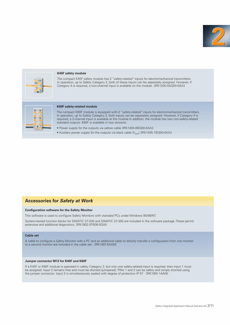
K45F safety module
The compact K45F safety module has 2 “safety-related” inputs for electromechanical transmitters.In operation, up to Safety Category 2, both of these inputs can be separately assigned. However, if Category 4 is required, a two-channel input is available on the module. 3RK1205-0AQ00-0AA3
K60F safety-related module
The compact K60F module is equipped with 2 “safety-related” inputs for electromechanical transmitters.In operation, up to Safety Category 2, both inputs can be separately assigned. However, if Category 4 isrequired, a 2-channel input is available at the module.In addition, the module has two non-safety-related standard outputs. K60F is available in two versions:
• Power supply for the outputs via yellow cable 3RK1405-0BQ00-0AA3
• Auxiliary power supply for the outputs via black cable (Vaux) 3RK1405-1BQ00-0AA3
Accessories for Safety at Work
Configuration software for the Safety Monitor
This software is used to configure Safety Monitors with standard PCs under Windows 95/98/NT.
System-tested function blocks for SIMATIC S7-200 and SIMATIC S7-300 are included in the software package.These permit extensive and additional diagnostics. 3RK1802-2FB06-0GA0
Cable set
A cable to configure a Safety Monitor with a PC and an additional cable to directly transfer a configuration from one monitorto a second monitor are included in the cable set - 3RK1901-5AA00
Jumper connector M12 for K45F and K60F
If a K45F or K60F module is operated in safety Category 2, but only one safety-related input is required, then input 1 must be assigned. Input 2 remains free and must be shorted (jumpered). PINs 1 and 2 can be safety and simply shorted using the jumper connector. Input 2 is simultaneously sealed with degree of protection IP 67 - 3RK1901-1AA00

2/12 Safety Integrated Application Manual Siemens AG
• For applications in compliance withCategory 2, both inputs at the safetymodule can be used.
• This means that two electromechani-cal sensors, in compliance withCategory 2, can be operated at anAS-Interface address.
• Inputs 1 and 2 can each be equippedwith a 1-channel standard sensor.
• PINs 1 and 2 are each assigned atboth inputs.
• If only input 1 is assigned in compli-ance with Category 2 and input 2 isnot assigned, then pins 1 and 2 mustbe shorted (connected together) atinput 2 (jumper connector IP 67 asaccessory).
2.2.2 Connecting Examples
Fig. 2/10Circuit example, Safety Monitor with enable circuits
1.13/1.14-1.23/1.241.321.Y11.Y2
L/+L
Enable circuit (K1, K2)Signaling circuit (OUT1)Contactor monitoring (EDM)Start 1 (optional)
L/+M/N
M
K1
K2
K3
K4
K1 K2 K3 K4
Enable circuit I
2.13/2.14-2.23/2.242.322.Y12.Y2
Enable circuit (K3, K4)Signaling circuit (OUT2)Contactor monitoring (EDM)Start 2 (optional)
Enable circuit II
L/+L
L/+M/N
M
K1
K2 Start 1
K1 K2
Start 2Start 1
M
K3
K4
L/+
2.Y1M
K1
K2
L/+
1.Y1M
K1
K2
L/+
1.Y1
Circuit example, Safety Monitorwith one/two enable circuits
Category 2 according to EN 954-1 with safety-related modules
Fig. 2/11Category 2 with safety-related modules
Safetymodule
Safetymonitor
Safetymodule
Fig. 2/12Protective door monitoring, Category 2with position switch and safety-relatedmodule
Safetymodule
Safetymonitor
ClosedOpen
ClosedOpen
S1 S2
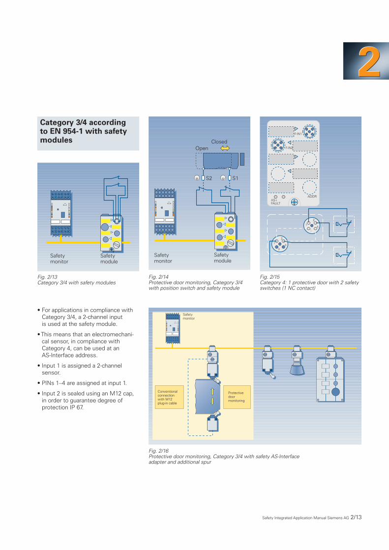
• For applications in compliance withCategory 3/4, a 2-channel input is used at the safety module.
• This means that an electromechani-cal sensor, in compliance with Category 4, can be used at an AS-Interface address.
• Input 1 is assigned a 2-channelsensor.
• PINs 1–4 are assigned at input 1.
• Input 2 is sealed using an M12 cap,in order to guarantee degree ofprotection IP 67.
222Category 3/4 according to EN 954-1 with safetymodules
Fig. 2/13Category 3/4 with safety modules
Safetymodule
Safetymonitor
Fig. 2/14Protective door monitoring, Category 3/4 with position switch and safety module
Fig. 2/15Category 4: 1 protective door with 2 safetyswitches (1 NC contact)
Safetymodule
Safetymonitor
ClosedOpen
S2 S1
F-IN1
F-IN2
AS-iFAULT
ADDR
1
2
34
1
2
34
Fig. 2/16Protective door monitoring, Category 3/4 with safety AS-Interface adapter and additional spur
Safetymonitor
Conventionalconnectionwith M12plug-in cable
Protectivedoormonitoring
Safety Integrated Application Manual Siemens AG 2/13

Safety-related data can be exchangedbetween two AS-Interface networksusing Safety at Work components.To realize this, an enable circuit of a Safety Monitor from network 1 isconnected to a safety input at amodule from network 2.
For this application, for the transferredsafety signal, a response time of max.80 ms is obtained (2 x 40 ms)
2/14 Safety Integrated Application Manual Siemens AG
Exchanging safety-relatedsignals between two AS-Interface networks
Fig. 2/17Exchanging safety-related signals between two AS-Interface networks (Category 4)
Safetymonitor
Safetymodule
AS-Interface network 1 AS-Interface network 2

Groups of safety-related signals can be formed using AS-Interface Safety at Work.
The diagram shows a network whichincludes, in addition to standard com-ponents, two Safety Monitors, eachwith a 2-channel enable circuit and foursafety-relevant slaves. For instance,each monitor is assigned a section ofthe plant or system which can then bepowered-down via an appropriateenable circuit.
A PC is used to assign the safety-related slaves to the Safety Monitors.
This example has been configured so that the safety module and EMER-GENCY STOP 1 acts on Safety Monitor1. For example, if EMERGENCY STOP1 is pressed, the plant section,assigned to the monitor, is shut downvia the appropriate enable circuit.
EMERGENCY STOP 2 acts on bothSafety Monitors, i.e. if EMERGENCYSTOP 2 is pressed, both plant sectionsare shut down.
EMERGENCY STOP 3 only acts onSafety Monitor 2 and shuts down theplant section assigned to it.
As shown in this example, severalSafety Monitors can be connected toan AS-Interface network.This meansthat not only can safety-related signalsbe grouped, but it is also possible tocombine various operating modes in a single network.
Siemens AG Safety Integrated Application Manual 2/15
222Forming groups of safety-related signalsusing Safety at Work
Fig. 2/18Forming groups of safety-related signals allows individual plant sections to be shut down
Standard PLC andstandard master
Safety at Work – safety-related components formed into groups
Safety monitor 1 Safety monitor 2
Standardmodule
Standard power supply
EMER-GENCYSTOP 1
Standardmodule
Safetymodule
EMER-GENCYSTOP 2
EMER-GENCYSTOP 3

2/16 Siemens AG Safety Integrated Application Manual
An AS-Interface network with Safety atWork components can also be subordi-nate to an ET 200S SIGUARD station.
To realize this, an enable circuit of aSafety Monitor is incorporated in thesafety circuit of the ET 200S SIGUARD.The response time of the ET 200SSIGUARD of about 20 ms is added tothe response time of Safety at Work(max. 40 ms).
Safety at Work alsooperates together withET 200S SIGUARD
Fig. 2/19Safety at Work also operates closely with ET 200S SIGUARD
Safety Monitorin the AS-Interface networkwith Safety at Work ET 200S SIGUARD on PROFIBUS
IM 151
PM
-D
Load group 1
PM
-X
DS DS
Terminating module
PM
-DF
DS RS
Supplycontactor
Term
inat
ing
mod
ule
PM
-X
Load group 2 with safety technology
Terminating cover
PM
-X
2.2.3 Connection Assignments

222
Safety Integrated Application Manual Siemens AG 2/17
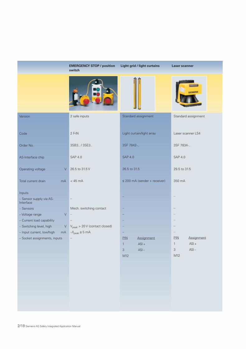
2.2.4 Technical Data
The Safety Monitor monitors thesafety-relevant data transfer for“AS-Interface Safety at Work”.
There are 2 versions (1 safety-related2-channel enable circuit or 2 safety-related enable circuits). A PC programis used to assign the safety-relatedslaves to the safety-related enablecircuits. It is possible to have severalSafety Monitors in one network. Cate-gory 4 in compliance with EN 954-1can be achieved using the appropriatesafety-related AS-Interface slaves andthe appropriate circuitry.
Each safety-related enable circuit hasthe following rated operating currents(relay output):
Rated operating current Ie/AC-12 to 250 V, 2A
Ie/AC-15 115 V, 2 A
230 V, 2 A
Ie/DC-12 to 24 V, 2 A
Ie/DC-13 24 V, 1 A
115 V, 0.1 A
230 V, 0.05 A
Safety Monitor
2/18 Siemens AG Safety Integrated Application Manual
Version
Code
Order No.
AS-Interface chip
Operating voltage V
Total current drain mA
Inputs
– Sensor supply via AS-Interface
– Sensors
– Voltage range V
– Current load capability
– Switching level, high V
– Input current, low/high mA
– Socket assignments, inputs
2 safe inputs
2 F-IN
3SB3.. / 3SE3..
SAP 4.0
26.5 to 31.5 V
< 45 mA
–
Mech. switching contact
–
–
Vpeak > 20 V (contact closed)
–/Ipeak ≥ 5 mA
–
Standard assignment
Light curtain/light array
3SF 7842-..
SAP 4.0
26.5 to 31.5
≤ 200 mA (sender + receiver)
–
–
–
–
–
–
PIN Assignment
1 ASI +
3 ASI –
M12
Standard assignment
Laser scanner LS4
3SF 7834-..
SAP 4.0
29.5 to 31.5
350 mA
–
–
–
–
–
–
PIN Assignment
1 ASI +
3 ASI –
M12
EMERGENCY STOP / positionswitch
Light grid / light curtains Laser scanner

Siemens AG Safety Integrated Application Manual 2/19
222
Outputs
I/O configuration
ID/ID2 code– short-circuit protection– induction protection– external 24 V DC power supply
– watchdog
Assignment of the data bits
AS-Interface certificate
Approvals
Degree of protection
Ground connection
Ambient temperature
Storage temperature
No. of I/O sockets
Status display– I/O display– Vaux
– AS-Interface/diagnostics display
Connection
Address assignment
–
0
B/–integratedintegrated–
integrated
available
UL, CSA
IP 67, IP 20 for EMERGENCYSTOP in the front panel
–
–25 °C to 60 °C
–25 °C to 85 °C
–
LED yellow – LED green/red
Via the mounting clip directly on the AS-Interface cable
The module keeps the lastaddress after the 15th addressassignment.
Conductorpair
red
black
Function
influences bitsD0 and D1 = channel 1
influences bitsD2 and D3 = channel 2
5
21
34
–
0
B/–integratedintegrated–
integrated
–
being prepared
being prepared
IP 65
0 °C to +50 °C
-20 °C to +60 °C
–
–––
M12 connector
–
–
0
B/–integratedintegrated–
integrated
–
available
UL, CSA, marine
IP 65
0 °C to +55 °C
-25 °C to +75 °C
–
–––
M12 connector
–
EMERGENCY STOP / positionswitch
Light grid / light curtains Laser scanner