Embed Size (px)
Citation preview

Delft University of Technology
FACULTY OF MECHANICAL, MARITIME AND MATERIALS ENGINEERING Department of Marine and Transport Technology
Mekelweg 2 2628 CD Delft the Netherlands Phone +31 (0)15-2782889 Fax +31 (0)15-2781397 www.mtt.tudelft.nl
Student: Johan van Jole Assignment type: Literature
Supervisor (TUD): Dr. Rudy Negenborn Report number: 2016.TL.8015 Supervisor (Company): -
Specialization: TEL Confidential: no Creditpoints (EC): 12
Subject: Control of Automated Container Terminals
In order to meet the increasingly tight demands on
transport performance, manufacturers are developing robots for transport technology (such as cranes, AGVs,
lifts, …) that can in an automated or even fully
autonomous way transport materials and/or equipments from one place to another. Fig. 1 shows an example: a
container terminal consisting of multiple automated cranes, made by ZPMC in China. Each of the cranes
operates in a part of the overall container terminal,
picking up containers at one point, and delivering them to another.
The operation of such robots involves all kinds of uncertainty. Dynamic properties of robots may change
due to aging of wheels, floors or tracks may be unexpectedly slippery, weather conditions may influence
swinging of container grabbers, containers may arrive in unexpected order, equipment fail, etc.
In order to ensure adequate operation of autonomous robots, the possible uncertainties and disturbances that can emerge have to be taken into account in their operation and handled effectively.
Obtaining an overview of uncertainties, disturbances, and ways of dealing with these is the topic of
this literature study.
In particular, you will address questions like:
What are autonomous robots? For what kind of transport technology are they used? How
would you define the systems within which these autonomous robots operate?
How do the autonomous robots determine what they have to do? What kind of information do
they require in order to determine their actions? How much uncertainty is there in this
information? What kinds of techniques have been proposed in the literature to obtain the information
required, and how do these techniques handle uncertainty and disturbances?
It is expected that you conclude your literature study with a written report, including conclusions and
recommendations for future research. The report must be written in English and must comply with the guidelines of the section. Details can be found on the website.
For more information, contact Dr. Rudy Negenborn.
The supervisor, Dr. Rudy Negenborn
Fig. 1: Model of an automated container
terminal (ZPMC, Shanghai).
Control of Automated ContainerTerminalsA Literature Review on Automated Container HandlingEquipment
Johan van Jole
Lite
ratu
reRe
sear
ch


Control of Automated ContainerTerminals
A Literature Review on Automated Container Handling Equipment
Literature Research
Johan van Jole
June 19, 2014
Faculty of Mechanical, Maritime and Materials Engineering (3mE) · Delft University ofTechnology

Copyright c⃝ Transportation EngineeringAll rights reserved.

Assignment Description
In order to meet the increasingly tight demands on transport performance, manufacturersare developing robots for transport technology (such as cranes, AGVs, lifts, ) that can inan automated or even fully autonomous way transport materials and/or equipments fromone place to another. Fig. 1 shows an example: a container terminal consisting of multipleautomated cranes, made by ZPMC in China. Each of the cranes operates in a part of theoverall container terminal, picking up containers at one point, and delivering them to another.
The operation of such robots involves all kinds of uncertainty. Dynamic properties of robotsmay change due to aging of wheels, floors or tracks may be unexpectedly slippery, weatherconditions may influence swinging of container grabbers, containers may arrive in unexpectedorder, equipment fail, etc.
In order to ensure adequate operation of autonomous robots, the possible uncertainties anddisturbances that can emerge have to be taken into account in their operation and handledeffectively. Obtaining an overview of uncertainties, disturbances, and ways of dealing withthese is the topic of this literature study.
In particular, you will address questions like:
• What are autonomous robots? For what kind of transport technology are they used?How would you define the systems within which these autonomous robots operate?
• How do the autonomous robots determine what they have to do? What kind of infor-mation do they require in order to determine their actions? How much uncertainty isthere in this information?
• What kinds of techniques have been proposed in the literature to obtain the informationrequired, and how do these techniques handle uncertainty and disturbances?
It is expected that you conclude your literature study with a written report, including con-clusions and recommendations for future research. The report must be written in Englishand must comply with the guidelines of the section. Details can be found on the website.
Literature Research Johan van Jole

ii
Johan van Jole Literature Research

Table of Contents
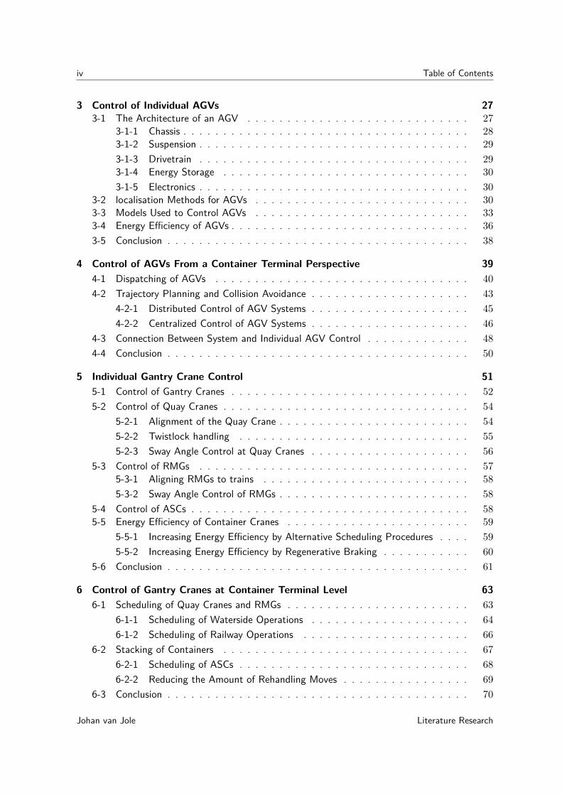
1 Container Handling at Container Terminals 11-1 Background and Trends in Containerized Transport . . . . . . . . . . . . . . . . 11-2 Container Terminal Processes . . . . . . . . . . . . . . . . . . . . . . . . . . . . 6
1-2-1 Container Handling Processes . . . . . . . . . . . . . . . . . . . . . . . . 61-2-2 Business Processes . . . . . . . . . . . . . . . . . . . . . . . . . . . . . 9
1-3 Structure of the Report . . . . . . . . . . . . . . . . . . . . . . . . . . . . . . . 91-3-1 Research Questions . . . . . . . . . . . . . . . . . . . . . . . . . . . . . 101-3-2 Approach . . . . . . . . . . . . . . . . . . . . . . . . . . . . . . . . . . 101-3-3 Structure of the Report . . . . . . . . . . . . . . . . . . . . . . . . . . . 10
2 Equipment at Automated Container Terminals 132-1 Typical Automated Terminal Equipment . . . . . . . . . . . . . . . . . . . . . . 13
2-1-1 Quay Gantry Cranes . . . . . . . . . . . . . . . . . . . . . . . . . . . . . 14
2-1-2 Rail Mounted Gantry Cranes (RMGs) . . . . . . . . . . . . . . . . . . . 16
2-1-3 Automated Stacking Cranes (ASCs) . . . . . . . . . . . . . . . . . . . . 17
2-1-4 Automated Guided Vehicles (AGVs) . . . . . . . . . . . . . . . . . . . . 18
2-2 Alternative Types of Equipment . . . . . . . . . . . . . . . . . . . . . . . . . . . 20
2-2-1 Rubber Tired Gantry Cranes (RTGs) . . . . . . . . . . . . . . . . . . . . 21
2-2-2 Overhead Bridge Cranes (OBCs) . . . . . . . . . . . . . . . . . . . . . . 22
2-2-3 Straddle Carriers . . . . . . . . . . . . . . . . . . . . . . . . . . . . . . . 222-2-4 Multi-Trailer System (MTS) . . . . . . . . . . . . . . . . . . . . . . . . 23
2-2-5 Rail-Mounted Automated Guided Vehicles (RGVs) . . . . . . . . . . . . . 24
2-3 Conclusion . . . . . . . . . . . . . . . . . . . . . . . . . . . . . . . . . . . . . . 25
Literature Research Johan van Jole
iv Table of Contents
3 Control of Individual AGVs 273-1 The Architecture of an AGV . . . . . . . . . . . . . . . . . . . . . . . . . . . . 27
3-1-1 Chassis . . . . . . . . . . . . . . . . . . . . . . . . . . . . . . . . . . . . 283-1-2 Suspension . . . . . . . . . . . . . . . . . . . . . . . . . . . . . . . . . . 293-1-3 Drivetrain . . . . . . . . . . . . . . . . . . . . . . . . . . . . . . . . . . 293-1-4 Energy Storage . . . . . . . . . . . . . . . . . . . . . . . . . . . . . . . 303-1-5 Electronics . . . . . . . . . . . . . . . . . . . . . . . . . . . . . . . . . . 30
3-2 localisation Methods for AGVs . . . . . . . . . . . . . . . . . . . . . . . . . . . 303-3 Models Used to Control AGVs . . . . . . . . . . . . . . . . . . . . . . . . . . . 333-4 Energy Efficiency of AGVs . . . . . . . . . . . . . . . . . . . . . . . . . . . . . . 363-5 Conclusion . . . . . . . . . . . . . . . . . . . . . . . . . . . . . . . . . . . . . . 38
4 Control of AGVs From a Container Terminal Perspective 394-1 Dispatching of AGVs . . . . . . . . . . . . . . . . . . . . . . . . . . . . . . . . 404-2 Trajectory Planning and Collision Avoidance . . . . . . . . . . . . . . . . . . . . 43
4-2-1 Distributed Control of AGV Systems . . . . . . . . . . . . . . . . . . . . 454-2-2 Centralized Control of AGV Systems . . . . . . . . . . . . . . . . . . . . 46
4-3 Connection Between System and Individual AGV Control . . . . . . . . . . . . . 484-4 Conclusion . . . . . . . . . . . . . . . . . . . . . . . . . . . . . . . . . . . . . . 50
5 Individual Gantry Crane Control 515-1 Control of Gantry Cranes . . . . . . . . . . . . . . . . . . . . . . . . . . . . . . 525-2 Control of Quay Cranes . . . . . . . . . . . . . . . . . . . . . . . . . . . . . . . 54
5-2-1 Alignment of the Quay Crane . . . . . . . . . . . . . . . . . . . . . . . . 545-2-2 Twistlock handling . . . . . . . . . . . . . . . . . . . . . . . . . . . . . 555-2-3 Sway Angle Control at Quay Cranes . . . . . . . . . . . . . . . . . . . . 56
5-3 Control of RMGs . . . . . . . . . . . . . . . . . . . . . . . . . . . . . . . . . . 575-3-1 Aligning RMGs to trains . . . . . . . . . . . . . . . . . . . . . . . . . . 585-3-2 Sway Angle Control of RMGs . . . . . . . . . . . . . . . . . . . . . . . . 58
5-4 Control of ASCs . . . . . . . . . . . . . . . . . . . . . . . . . . . . . . . . . . . 585-5 Energy Efficiency of Container Cranes . . . . . . . . . . . . . . . . . . . . . . . 59
5-5-1 Increasing Energy Efficiency by Alternative Scheduling Procedures . . . . 595-5-2 Increasing Energy Efficiency by Regenerative Braking . . . . . . . . . . . 60
5-6 Conclusion . . . . . . . . . . . . . . . . . . . . . . . . . . . . . . . . . . . . . . 61
6 Control of Gantry Cranes at Container Terminal Level 636-1 Scheduling of Quay Cranes and RMGs . . . . . . . . . . . . . . . . . . . . . . . 63
6-1-1 Scheduling of Waterside Operations . . . . . . . . . . . . . . . . . . . . 646-1-2 Scheduling of Railway Operations . . . . . . . . . . . . . . . . . . . . . 66
6-2 Stacking of Containers . . . . . . . . . . . . . . . . . . . . . . . . . . . . . . . 676-2-1 Scheduling of ASCs . . . . . . . . . . . . . . . . . . . . . . . . . . . . . 686-2-2 Reducing the Amount of Rehandling Moves . . . . . . . . . . . . . . . . 69
6-3 Conclusion . . . . . . . . . . . . . . . . . . . . . . . . . . . . . . . . . . . . . . 70
Johan van Jole Literature Research
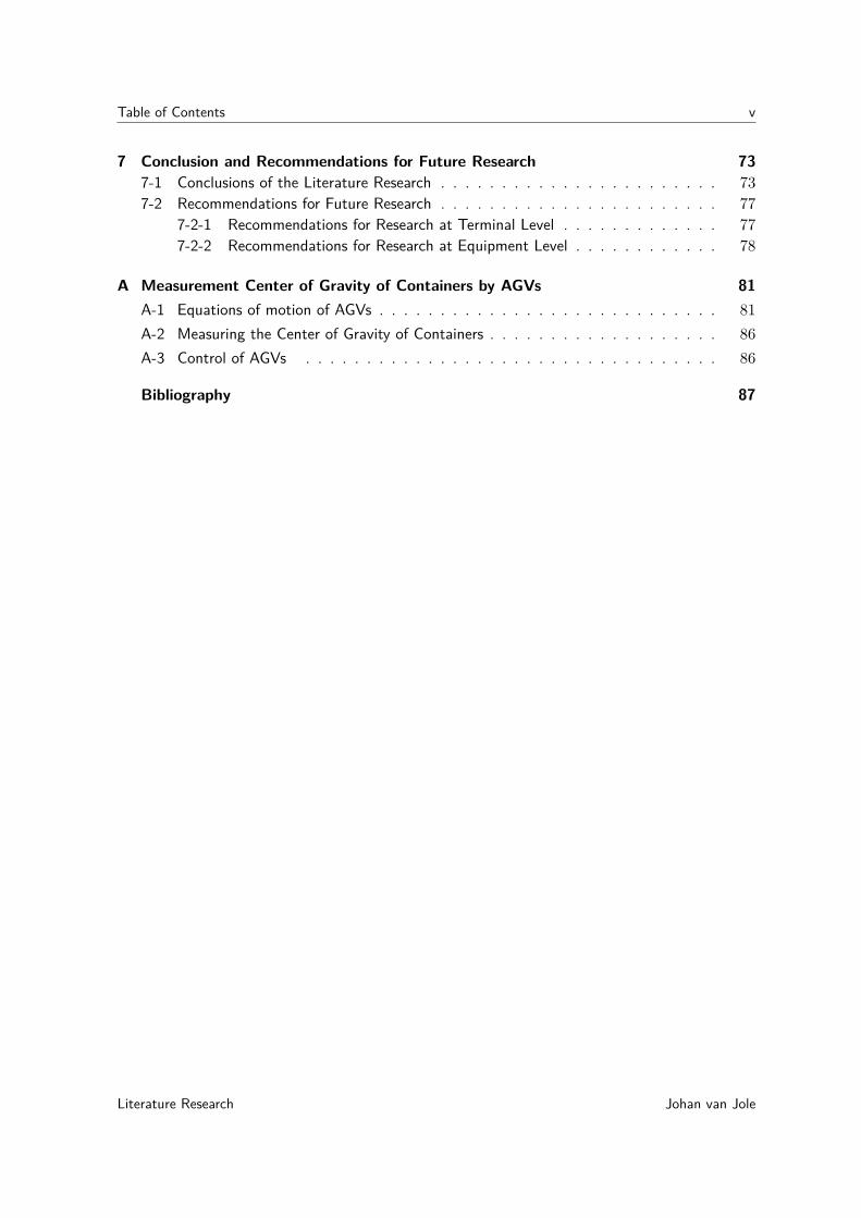
Table of Contents v
7 Conclusion and Recommendations for Future Research 737-1 Conclusions of the Literature Research . . . . . . . . . . . . . . . . . . . . . . . 737-2 Recommendations for Future Research . . . . . . . . . . . . . . . . . . . . . . . 77
7-2-1 Recommendations for Research at Terminal Level . . . . . . . . . . . . . 777-2-2 Recommendations for Research at Equipment Level . . . . . . . . . . . . 78
A Measurement Center of Gravity of Containers by AGVs 81A-1 Equations of motion of AGVs . . . . . . . . . . . . . . . . . . . . . . . . . . . . 81A-2 Measuring the Center of Gravity of Containers . . . . . . . . . . . . . . . . . . . 86A-3 Control of AGVs . . . . . . . . . . . . . . . . . . . . . . . . . . . . . . . . . . 86
Bibliography 87
Literature Research Johan van Jole

vi Table of Contents
Johan van Jole Literature Research
Chapter 1
Container Handling at ContainerTerminals
This chapter concerns the motivation for automated container terminals. An automatedcontainer terminal is a terminal where the operations are performed without any humanintervention. The first section provides an introduction into the background and thetrends surrounding container terminals. The second section describes the processes ofautomated container terminals. The final section covers the structure of the report.
Currently, more and more container terminals are automated in order to increase the pro-ductivity and lower the costs of handling containers. A lot of research has been performedat this subject. This literature research project provides an overview on the current state ofautomation at container terminals as well as the future developments regarding automatedcontainer terminals.
This research concerns automated deep-sea container terminals. The inland container ter-minals which are used to offload barges (vessels which are only applied for inland transporta-tion) are not considered. This research focusses on the automation of container handlingequipment.
1-1 Background and Trends in Containerized Transport
In order to obtain an insight into the relevance of automated container terminals, the back-ground of containerized transportation is outlined in this section. The current trends oncontainer terminals will be presented in this section as well, in order to clarify the relevanceof automated container terminals.
Literature Research Johan van Jole

2 Container Handling at Container Terminals
Containers have become an important asset in international trade for over 50 years. MichealBohlman (chairman of the ISO committee regarding containerized transport) argued eventhat "freight containers are, and are expected to remain, the most economical balance be-tween cargo security, transportation cost and speed of delivery for the majority of packedcargo" [1]. Over 90 percent of trade in non-bulk goods is transported by containers [1]. In theyear 2010, 114 million TEU (twenty foot equivalent unit) were shipped globally [2], of which1.6 million were handled in the Netherlands. Growth in container volumes are expected tolast at least until 2020 [3].
Container terminals are very important links in containerized transport. At container termi-nals, the containers change transport modality (the containers are transferred between trucks,trains and vessels). This enables the containers to reach their proper destination, with theproper mode of transportation (trucks, trains and vessels). The deep-sea vessels that providethe so called "economy of scale" for long distance transportation of containers are not able toreach the final destinations of the containers. The container terminal expands the transporta-tion network dedicated to containerized transportation and links all container transportationmodes together. An example of a container terminal is shown in Figure 1.
Figure 1: Overview of a container terminal (source:www.gcaptain.com)
The performance of container terminals is an important factor in the succes of container-ized transportation. The container terminals form the links between different transportationmodes, creating a transportation network that spans the entire globe. The outlook on in-creased volumes of container transportation calls for an increase in the productivity of con-tainer terminals in order to maintain the handling times of the vessels within acceptablelimits. The productivity of the container terminals needs to increase because otherwise theymight turn into the bottlenecks of containerized transport.
Johan van Jole Literature Research

1-1 Background and Trends in Containerized Transport 3
Control of the existing infrastructure is one of the methods that are used in order to increasethe container handling capacity of ports. Another method which increases the container han-dling capacity of ports is constructing more container terminals. Both approaches can beautomated, the existing infrastructure can be automated or the newly constructed terminalsare automated container terminals. Automation of container terminals is preferred over build-ing new terminals due to large investment costs involved when constructing new containerterminals. New terminals are only constructed when the capacity marge not sufficient tosatisfy the expected growth of container volumes of the port. New container terminals arecurrently only constructed in Rotterdam (Maasvlakte 2 [4]) and Qatar [5]. Most of the capac-ity increases at container terminals are realized by automating existing container terminals.
Automating the container handling processes improves the productivity regarding these pro-cesses. The cycle times of human operators vary across their shift and the handling perfor-mance depends on their level of skill and experience. In human operated terminals, there is areduced production during shift changes, which is no concern at an automated terminal. Theperformance of automated equipment remains costant, which is an improvement comparedto the performance of human operated terminals.
Another reason for automation is the reduced need for human operators. This factor isespecially important in countries where human labor is relatively expensive. Areas withhigh labor costs are for instance the European countries and countries in North America.Automation reduces the total operating costs of a container terminal. Automated containerhandling equipment can be more expensive than the human operated container handlingequipment. The payback time of the investment costs thus might be longer. The higherinvestment costs can be justified when the operating costs are reduced significantly. Theprofit margin per container handling move rises, meaning that the terminal makes moreprofit per handled container.
Next to the trend for automation of container terminals there is another trend: the trend ofincreasing the overall energy efficiency of the container terminal. The energy consumptionof container handling equipment at a terminal is fairly large. The price of energy in Europeis expected to rise more than 30 percent in the period 2010-2020 [6]. In order to keep han-dling costs as low as possible, the energy efficiency of the various types of equipment canbe increased. This development is not necessarily combined with the effort to automate theequipment. However, reduction of the energy requirement of automated container handlingequipment is easier to be obtained with respect to human operated machinery. When thecontroller is able to operate the equipment, it is only a relatively small step to incorporateenergy saving strategies.
Reduction of the total energy consumption at a container terminal also serves the demandfor more sustainable processes by society. Sustainability in this context was defined in [7] as"improving the social and economic conditions of an increasingly urbanized population whilepreserving the life systems and maintaining environmental quality". This means that theterminal should operate with a minimized influence on the environment without increasinghandling costs.
Literature Research Johan van Jole

4 Container Handling at Container Terminals
Table 1 lists the automated terminals that are either already in operation or are under de-velopment [8], [9]. Examples of automated container terminals that are currently underdevelopment are the APMT2 container terminal in Rotterdam [10] as well as terminals in theport of Brisbane, Australia [11].
Johan van Jole Literature Research

1-1 Background and Trends in Containerized Transport 5
Table 1: A list of automated container terminals.
Container Terminal City Country Region YearContainer Terminal Altenwerder Hamburg Germany Europe 2002Container Terminal Buchardkal Hamburg Germany Europe 2010ECT Euromax Rotterdam The Netherlands Europe 2008ECT Delta Terminal Rotterdam The Netherlands Europe 1993TTI Algeciras Algeciras Spain Europe 2010BEST Container Terminal Barcelona Spain Europe 2012DPW Antwerp Gateway Termi-nal
Antwerp Belgium Europe 2007
London Thamesport London Great-Britain Europe 2000APMT Norfolk Norfolk United States North America 2010APM Terminals Virginia Portsmouth United States North America 2007TraPac Los Angeles United States North America 2013Global Terminals New Jersey United States North America 2013Patrick Brisbane Autostrad Ter-minal
Brisbane Australia Australia 2009
Sydney International ContainerTerminals
Sydney Australia Australia 2012
Brisbane Container Terminals Brisbane Australia Australia 2012Khalifa Port Container Terminal Khalifa Abu Dhabi Middle-East 2012Hong Kong International Termi-nal 6-7
Hong Kong China Asia 2013
Pasir Panjang Bridge Crane Ter-minal Singapore
Singapore Singapore Asia 1997
Kaohsiung Evergreen Terminal Kaohsiung Taiwan Asia 2005Tobishima Terminal Nagoya Japan Asia 2008Pusan Newport InternationalTerminal
Busan South Korea Asia 2009
Korea Express Busan ContainerTerminal
Busan South Korea Asia 2007
Hanjin New Port Busan South Korea Asia 2009Taipei Port Container Terminal Taipei Taiwan Asia 2010Hyundai Pusan New-Port Termi-nal
Busan South Korea Asia 2010
Kao Ming Container Terminal Kaohsiung Taiwan Asia 2010Ohi Terminal Tokyo Japan Asia 2003APMT 2 Rotterdam The Netherlands Europe 2014Rotterdam World Gateway Rotterdam The Netherlands Europe 2014Long Beach Container Terminal Long Beach United States North America 2014Vado Ligure Vado Italy Europe 2016Kaohsiung Intercontinental Ter-minal
Kaohsiung Taiwan Asia t.b.a.
DP World Brisbane Brisbane Australia Australia t.b.a.
Literature Research Johan van Jole
6 Container Handling at Container Terminals
1-2 Container Terminal Processes
The previous section stated that automation of container terminals serves to meet the ongo-ing trends on container handling. In order to automate the container terminal, the processesnecessary to handle containers need to be determined. This section concerns the processesthat are necessary in order to operate a container terminal. The terminal processes are splitbetween the container handling processes and the business processes. The container handlingprocesses are the services that the terminal provides to its customers (the shipping lines, trainoperators, trucking operators etc.). The business processes deal with the organization andadministration taking place at the container terminal.
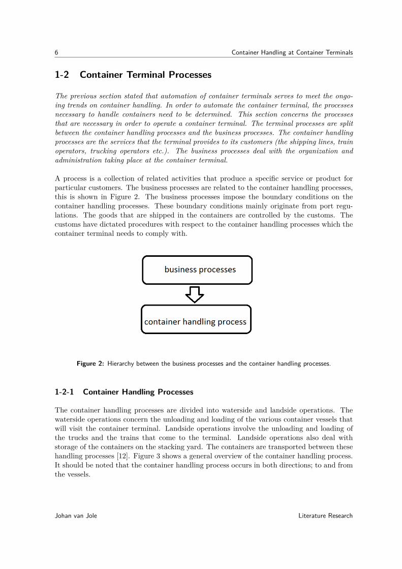
A process is a collection of related activities that produce a specific service or product forparticular customers. The business processes are related to the container handling processes,this is shown in Figure 2. The business processes impose the boundary conditions on thecontainer handling processes. These boundary conditions mainly originate from port regu-lations. The goods that are shipped in the containers are controlled by the customs. Thecustoms have dictated procedures with respect to the container handling processes which thecontainer terminal needs to comply with.
Figure 2: Hierarchy between the business processes and the container handling processes.
1-2-1 Container Handling Processes
The container handling processes are divided into waterside and landside operations. Thewaterside operations concern the unloading and loading of the various container vessels thatwill visit the container terminal. Landside operations involve the unloading and loading ofthe trucks and the trains that come to the terminal. Landside operations also deal withstorage of the containers on the stacking yard. The containers are transported between thesehandling processes [12]. Figure 3 shows a general overview of the container handling process.It should be noted that the container handling process occurs in both directions; to and fromthe vessels.
Johan van Jole Literature Research

1-2 Container Terminal Processes 7
The container handling process at the waterside starts with mooring the vessel at the quay.The containers that need to be unloaded are lifted off the vessel. These containers are trans-ported to the container stack, where the containers are stored until they’re picked up byanother client. The containers that are loaded onto the vessel are retrieved from the stack,transported towards the vessel and the containers are subsequently lifted onto the vessel.
The handling processes at the landside operation unload the import containers from thetrucks and trains. The containers are stored in the stack and the export containers are re-trieved from the stack and transported to the trucks and the trains. The containers aresubsequently lifted on the trucks and the trains. Landside operations are also in control ofthe stack.
Scheduling of the container handling operations (vessels, trains and trucks) is also consideredto be a part of the container handling process. Scheduling of the container handling operationsconcerns determining the order in which the vessels, trucks and trains are handled.
Figure 3: Overview of the container handling processes at a container terminal [13]
Table 2 shows the types of equipment that are in use at the 10 most recently automated con-tainer terminals. Not all container terminals are entirely automated, some container terminalsdeploy reach stackers in order to handle containers. There is little variation in the equipmenttypes used to handle the vessels and trains, the only difference concerns the horizontal trans-portation function at container terminals. When considering the horizontal transportation inTable 2 the AGVs are most frequently used. One terminal uses automated straddle carriers,while the rest of the terminals still use human operated equipment in order to perform thehorizontal transportation function.
Literature Research Johan van Jole

8 Container Handling at Container Terminals
Table2:
Equipment
usedat
automated
containerterminals
containerterm
inalhorizontal
trans-portation
handlingof
ves-sels
handlingoftrains
handlingoftrucks
stackingcontainers
reference
Rotterdam
World
Gate-
way
AG
VQ
uaycrane
RM
GA
SCA
SC[10]
APM
T2
AG
VQ
uaycrane
RM
GA
SCA
SC[10]
LongB
eachC
ontainerTerm
inalA
GV
Quay
craneR
MG
ASC
ASC
[14]
Hong
Kong
Interna-tionalTerm
inal6-7R
eachstackers/Frontloaders
Quay
craneR
MG
RTG
RTG
[15]
Khalifa
PortC
ontainerTerm
inalShuttle
Carriers
Quay
craneR
eachstackers
ASC
ASC
[16]
BrisbaneC
ontainerTer-m
inalA
utomated
strad-dle
carriersQ
uaycrane
RM
GA
utomated
strad-dle
carriersA
utomated
straddlecarriers
[11]
SydneyInternational
Container
Terminals
Tractor-trailersystem
sQ
uaycrane
RM
GA
SCA
SC[17]
GlobalTerm
inalsStraddle
carriersQ
uaycrane
RM
GA
SCA
SC[18]
TraPacR
eachStackers
Quay
craneR
MG
ASC
ASC
[9]B
ESTC
ontainerTermi-
nalA
GV
Quay
craneR
MG
ASC
ASC
[10]
Johan van Jole Literature Research

1-3 Structure of the Report 9
1-2-2 Business Processes
Business processes support the container handling processes of the container terminal. Ex-amples of business processes are contact with the clients, charging of the clients, checking forcompliance with port regulations and maintenance of the container handling equipment.
One important business process is checking for compliance with port regulations. Ports arein general areas which are heavily regulated. Port regulations state which procedures areallowed and under which circumstances. For instance, when a container is lifted from thevessel directly onto a truck in the port of Salalah (a port in Oman), the port authorities mustreceive a notification 24 hours in advance [19]. These kind of regulations are found in all portsaround the globe.
The container handling processes must comply with these regulations and a process must bein place to check for compliance with the regulations that are enforced by the authorities.
Automation of container terminals does not only apply to the container handling process,the business process is automated as well. An example concerns the Dutch custom proce-dures at all ports that are located in the Netherlands. The Dutch customs have developeda software tool which is able to automatically handle the custom declarations of the shippedcargo [20].
Terminal management software tools are developed in order to automate some of the adminis-trative processes that are in place at container terminals [21]. For example, transport planningprocesses are automated and the system is coupled with the ERP system of a terminal inorder to automatically charge the client when a container is leaving the terminal.
A connection between the container handling and business process exists through the plan-ning of the container handling operations. When containers leave the terminal, the containerhandling process lets the business process know that the task has been fulfilled and the clientcan be charged. When the container terminal receives a new request to service a vessel, trainor truck, this request will be forwarded to the container handling process. The containerhandling process subsequently schedules this new request.
The business processes need to be considered when a container terminal is automated entirelydue to the connection between the container handling and the business processes. However,because the scope of this research is on the automation of the container handling process,automation of the business processes will not be covered in this report.
1-3 Structure of the Report
This report lists the results of a literature review of container terminals, with the focus on deep-sea container terminals. This section contains the research questions, the research approachas well as the structure of the report
Literature Research Johan van Jole

10 Container Handling at Container Terminals
1-3-1 Research Questions
This report concerns the automation of deep-sea container terminals. The main researchquestion is:
"How can container handling equipment be automated?"
The main question is supported by 4 subquestions. The 4 subquestions that support themain question of this research are:
• What are the current trends on containerized transporation and container terminals?
• What is the current state of automation of container handling equipment?
• What parameters are involved in automating container handling equipment?
• What models and control techniques are used in automated container handling equip-ment?
• What are the current limitations in automating container terminals?
1-3-2 Approach
Table 2 shows that the equipment that is used at (automated) container terminals is differentfor each terminal. All types of container terminal equipment need to be discussed, alongwith their potential to be automated. Table 2 also indicated that in the case of automatedcontainer terminals that are estiblished recently (this table consists of data from terminalsautomated from 2011 onwards) a number of equipment types are deployed more frequentlythan others. These types of equipment are AGVs, RMGs, ASCs and quay cranes.
The control of individual pieces of equipment is considered for the frequently used types ofcontainer handling equipment. The next step is to consider the control of these types ofequipment at container terminal level. These two levels of control need to be considered inorder to determine the current limitations of automating container handling equipment.
When the current state of automation of container terminal equipment is established, direc-tions for future research in this field are constructed.
1-3-3 Structure of the Report
This chapter discussed the motivation for automation of container terminals as well as thetrends concerning container terminals. The major trend next to automation is the reductionof energy consumption of container terminal equipment. The container handling and businessprocesses at container terminals are discussed in this chapter as well.
Chapter 2 continues with the types of equipment that are used in the container handlingprocess at automated container terminals. The frequently used types of container handlingequipment as well as the alternative types of equipment that are also suited to be used atautomated container terminals are covered.
Johan van Jole Literature Research

1-3 Structure of the Report 11
Subsequently, the frequently used types of terminal equipment at automated container termi-nals are emphasized. As one of the frequently used types of automated terminal equipment;the control of AGVs at an individual level and at a system level level is discussed in chapters3 and 4 respectively.
The other types of frequently used terminal equipment are gantry cranes. Chapter 5 concernsthe control of gantry cranes at an individual level. Chapter 6 discusses the control of gantrycranes at terminal level.
Chapter 7 concludes this report with a summary on the automation of container handlingequipment. The answers to the research questions are presented and suggestions for futureresearch on this subject are provided.
Figure 15 shows the schematic representation of the structure of the report.
Figure 4: The structure of the report
Literature Research Johan van Jole

12 Container Handling at Container Terminals
Johan van Jole Literature Research

Chapter 2
Equipment at Automated ContainerTerminals
The previous chapter introduced the container handling processes. This chapter lists thetypes of equipment that are used in these processes. The first section covers the commontypes of equipment found at automated container terminals. The second section covers thealternative types of equipment that can be used at automated container terminals. Thegeneral characteristics of the various types of equipment are evaluated in both sections.The last section concludes this chapter.
2-1 Typical Automated Terminal Equipment
This section concerns the most used types of equipment at automated container terminals. Atautomated container terminals, vessels are handled by quay gantry cranes, stacking is pro-vided by automated stacking cranes, train loading is performed by rail mounted gantry cranesand terminal transportation is performed by automated guided vehicles.
The choice between different types of container handling equipment is based on several perfor-mance indicators. The performance indicators reflect the objectives of the terminal operator.The performance indicators are used to determine which type of equipment is suited for thetask that is considered as well as the specification of that type of equipment. Saanen [22]proposes a number of performance indicators for all aspects of a container terminal. Theproposed performance indicators reflect the productivity of equipment and are measured inmoves per hour, equipment cycles per hour and the number of containers handled per hour.
Literature Research Johan van Jole
14 Equipment at Automated Container Terminals
The type and number of container handling equipment that is used at the terminal dependson the specification. The specification of a certain type of container handling equipment liststhe required capacity, required operating velocities, its maximum weight and its maximum orminimum dimensions. The performance objectives of the container terminal are determinedby each terminal operator, therefore the performance objectives of each container terminalare different [22]. Thus the major performance indicators are different for each containerterminal, which means that the specifications of container handling equipment are differentat each container terminal. Although the conditions at each terminal are different, manyautomated terminals make use of the same types of equipment. The general characteristicsof these types of equipment are covered in this section.
2-1-1 Quay Gantry Cranes
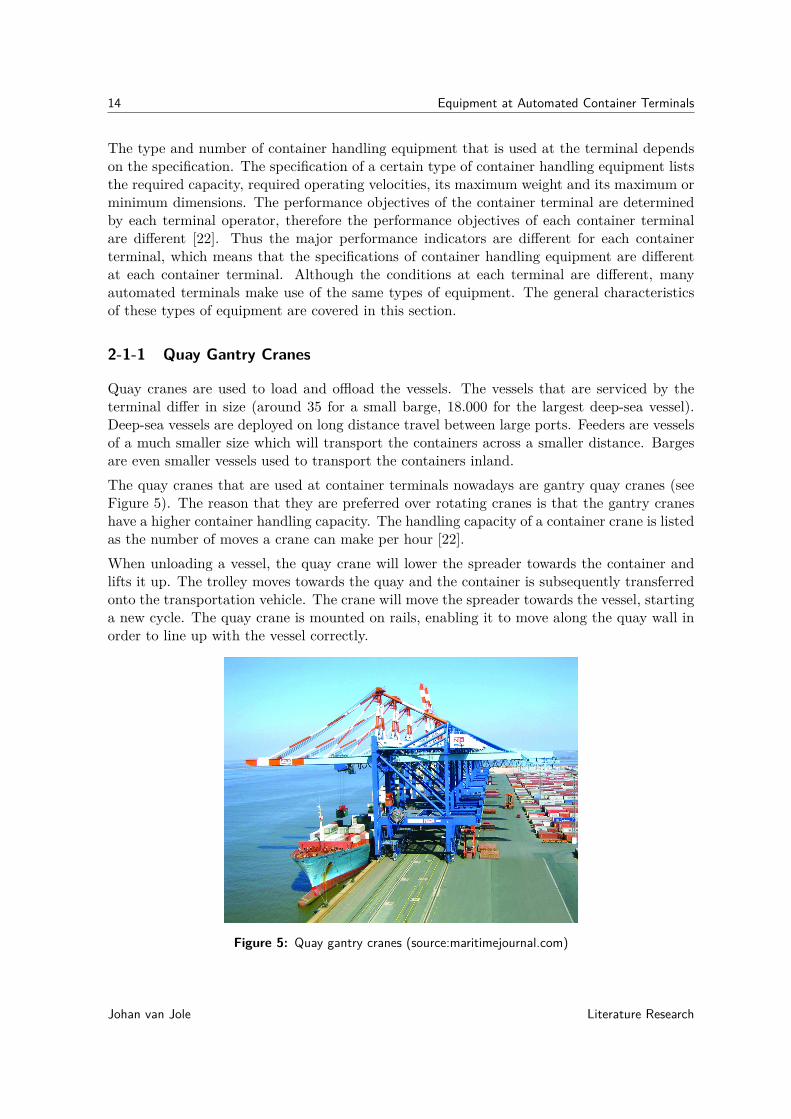
Quay cranes are used to load and offload the vessels. The vessels that are serviced by theterminal differ in size (around 35 for a small barge, 18.000 for the largest deep-sea vessel).Deep-sea vessels are deployed on long distance travel between large ports. Feeders are vesselsof a much smaller size which will transport the containers across a smaller distance. Bargesare even smaller vessels used to transport the containers inland.The quay cranes that are used at container terminals nowadays are gantry quay cranes (seeFigure 5). The reason that they are preferred over rotating cranes is that the gantry craneshave a higher container handling capacity. The handling capacity of a container crane is listedas the number of moves a crane can make per hour [22].When unloading a vessel, the quay crane will lower the spreader towards the container andlifts it up. The trolley moves towards the quay and the container is subsequently transferredonto the transportation vehicle. The crane will move the spreader towards the vessel, startinga new cycle. The quay crane is mounted on rails, enabling it to move along the quay wall inorder to line up with the vessel correctly.
Figure 5: Quay gantry cranes (source:maritimejournal.com)
Johan van Jole Literature Research
2-1 Typical Automated Terminal Equipment 15
Two important measures that improve the productivity of the crane are double trolley cranesas well as special spreaders.
Double trolley quay cranes decouple the processes of handling the vessel and (un-)loadingthe transportation equipment. The main trolley handles the vessel and the secondary trolleyhandles the horizontal transportation equipment. Both trolleys are connected by a platformthat is mounted on the crane. The total cycle time of the quay crane is lowered, improvingthe productivity of the crane.
With tandem operation, two or more spreaders are be attached to the trolley [23]. Thisenables the crane to lift two or three 40-foot containers in one cycle. The handling capacity isimproved, given that the terminal transportation is able to keep up with the handling speedof the crane. At the end of each cycle, the number of horizontal transportation equipmentmust equal the number of spreaders that are attached to the trolley.
Alternatively, twin-lift operation can be considered. Twin-lift operation is when one spreaderis able to lift two 20 foot containers in one cycle. The advantage with respect to tandem opera-tion is that this system can be implemented at every container terminal without adjustmentsin the horizontal transportation infrastructure. The disadvantage is that the performancegain is relatively small.
Automation of container cranes is considered because the quay cranes can become the limitingfactor in container terminal productivity in the future [24]. Automation of quay cranes is in aless developed state when compared to the cranes used elsewhere at the terminal because theoperating environment poses more challenges. Examples of these challenges are movementsof the vessels and increased influence of the wind impacting on the container and the crane.
Table 3 shows the key parameters of a quay crane. The parameters are from a Liebherr superpost-panamax/megamax STS container crane [25].
Literature Research Johan van Jole

16 Equipment at Automated Container Terminals
Table 3: Key parameters of a quay crane.
parameter value unitmaximum crane width (buffer to buffer) 27 mgantry width 18.2 mgantry span (distance between the rails) 15-35 mmaximum lifting height 35-49 moutreach (length of boom that is above the ves-sel)
46-70 m
backreach (part of boom that points towards thelandside)
0-25 m
maximum width of trolley 7.6 msafe working load tandem operation 85 tonsafe working load twin-lift operation 65 tonhoisting speed 60-150 (1-2.5) m/min (m/s)trolley speed 180-210 (3-3.5) m/min (m/s)crane travel speed 45 (0.75) m/min (m/s)trolley weight - tontotal crane weight 1920-2560 ton
2-1-2 Rail Mounted Gantry Cranes (RMGs)
Rail-Mounted Gantry Cranes (RMGs) are used at a number of container terminals for loadingand offloading trains. Figure 6 shows a human-operated RMG, which is in constructionentirely identical compared to an automated RMG. The RMGs that are used at terminalsgenerally span several train tracks.
Figure 6: Human operated RMG (source:www.konecranes.com)
Johan van Jole Literature Research
2-1 Typical Automated Terminal Equipment 17
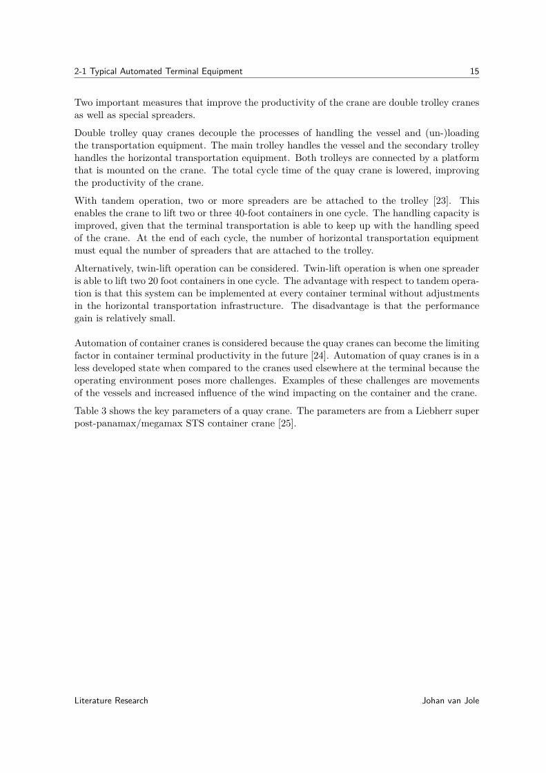
RMGs can already be automated because (contrary to the vessels at the quay cranes) thetrains and trucks are stationary with respect to the RMG crane. The position of the spreaderon an RMG is measured with laser based guidance systems [26]. The crane gantry positioncan be monitored by RFID sensors that are located alongside the track. The trolley positionis measured in two ways; one way is to use an incremental encoder, the other is to use a laserrange finder. The hoist position of the spreader is often measured using incremental encoders.Table 4 shows the specification of an RMG built by Konecranes [27].
Table 4: Key parameters of an RMG crane.
parameter value unitmaximum crane width (buffer to buffer) - mmaximum gantry span (distance between the rails) 50 mmaximum lifting height 21 msafe working load 50 tonhoisting speed with an empty spreader 90 (1.5) m/min (m/s)hoisting speed with 40 ton load 45 (0.75) m/min (m/s)maximum trolley speed 76 (1.27) m/min (m/s)crane travel speed with an empty spreader 150 (2.5)crane travel speed with 40 ton load 140 (2.33) m/min (m/s)trolley weight - tontotal crane weight - ton
2-1-3 Automated Stacking Cranes (ASCs)
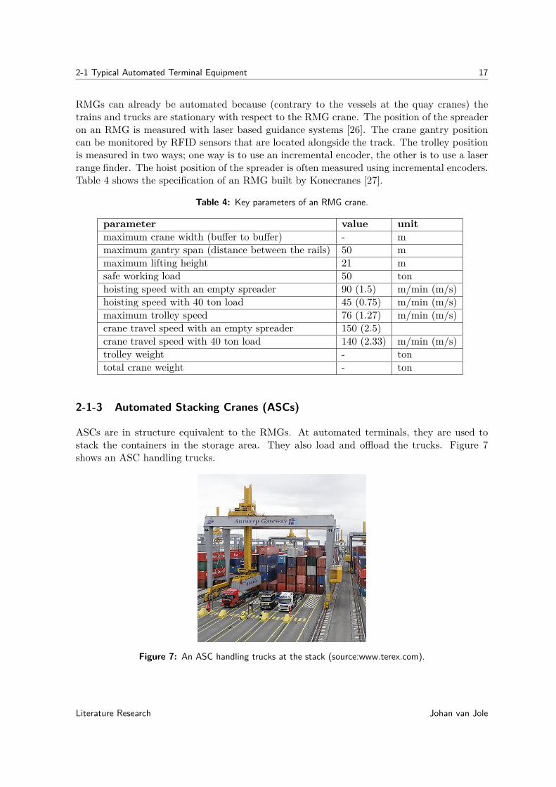
ASCs are in structure equivalent to the RMGs. At automated terminals, they are used tostack the containers in the storage area. They also load and offload the trucks. Figure 7shows an ASC handling trucks.
Figure 7: An ASC handling trucks at the stack (source:www.terex.com).
Literature Research Johan van Jole

18 Equipment at Automated Container Terminals
It is favorable with respect to the total amount of handling moves to serve the trucks directlyfrom the stack. The horizontal terminal transportation is connected at the other end of thestack. The ASC spans several rows of containers, the amount of rows being covered by theASC depends on the specification of the equipment objectives. The specification of the ASCis determined by the terminal operator.
When stacking a container, scanning lasers which are mounted on the trolley measure theposition of the container with respect to the containers below it. Optical laser systems areused in order to determine the distance and angle to any surface. This enables the ASC toaccurately position the spreader in order to lift a container.
Collision prevention is an important feature, because in most cases two or more ASCs aremounted on the same rail. The ASCs are equipped with laser range finders which are ableto detect all kinds of objects (transport equipment, other cranes, etc.) in order to preventcollisions from happening.
Table 5 lists the specification of an ASC built by Terex Port Solutions [28].
Table 5: Key parameters of an ASC.
parameter value unitmaximum crane width (buffer to buffer) 13.5 mgantry span (for a stack with 9 container rows) 28 mmaximum lifting height (for a stack of max. 5 containers high) 17 msafe working load - tonhoisting speed at full load 39 (0.65) m/min (m/s)hoisting speed with empty spreader 72 (1.2) m/min (m/s)maximum trolley speed 60 (1) m/min (m/s)crane travel speed 240 (4) m/min (m/s)maximum trolley acceleration 0.4 m/s2
maximum gantry acceleration 0.4 m/s2
maximum hoisting acceleration 0.35 m/s2
minimum working distance between two ASCs 2 TEUtrolley weight - tontotal crane weight - tonend-to-end container spacing 0.5 mside-to-side container spacing 0.4 m
2-1-4 Automated Guided Vehicles (AGVs)
Automated Guided Vehicles (AGVs) are frequently used for transportation tasks at automatedcontainer terminals. The vehicles are autonomous in the sense that they will calculate theirown route towards the destination position. AGVs are deployed at automated containerterminals for transporting containers at the container terminal.
Johan van Jole Literature Research
2-1 Typical Automated Terminal Equipment 19
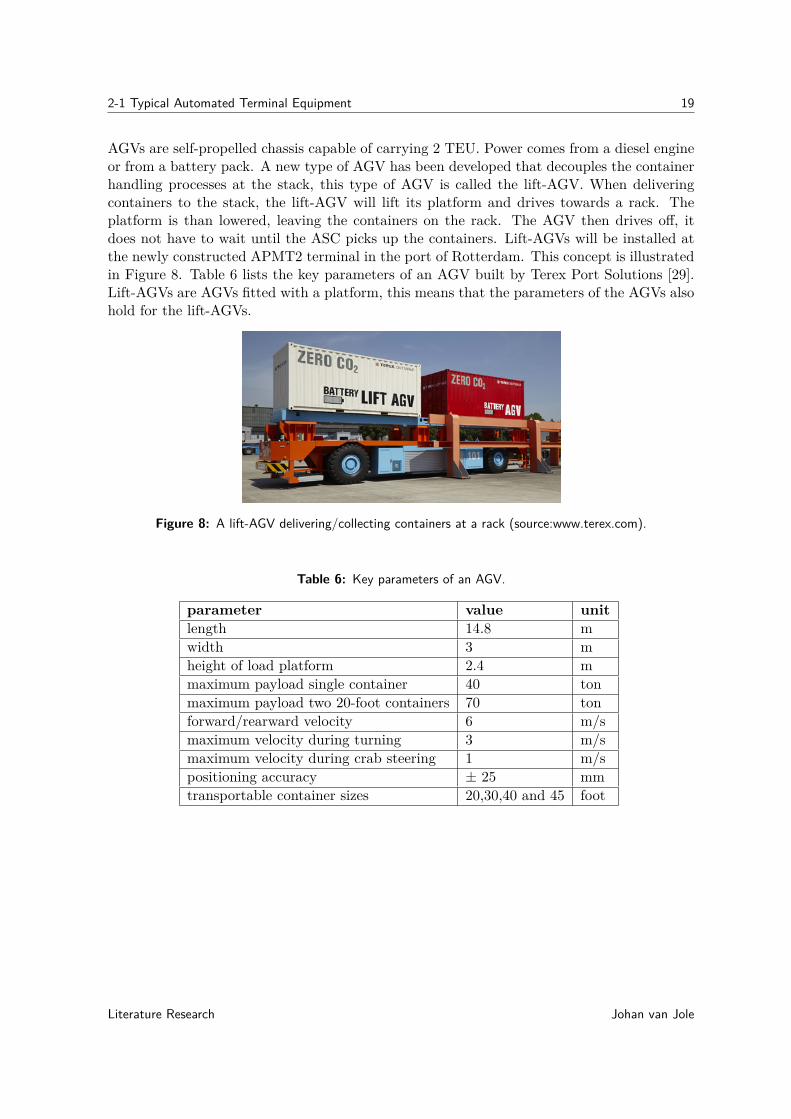
AGVs are self-propelled chassis capable of carrying 2 TEU. Power comes from a diesel engineor from a battery pack. A new type of AGV has been developed that decouples the containerhandling processes at the stack, this type of AGV is called the lift-AGV. When deliveringcontainers to the stack, the lift-AGV will lift its platform and drives towards a rack. Theplatform is than lowered, leaving the containers on the rack. The AGV then drives off, itdoes not have to wait until the ASC picks up the containers. Lift-AGVs will be installed atthe newly constructed APMT2 terminal in the port of Rotterdam. This concept is illustratedin Figure 8. Table 6 lists the key parameters of an AGV built by Terex Port Solutions [29].Lift-AGVs are AGVs fitted with a platform, this means that the parameters of the AGVs alsohold for the lift-AGVs.
Figure 8: A lift-AGV delivering/collecting containers at a rack (source:www.terex.com).
Table 6: Key parameters of an AGV.
parameter value unitlength 14.8 mwidth 3 mheight of load platform 2.4 mmaximum payload single container 40 tonmaximum payload two 20-foot containers 70 tonforward/rearward velocity 6 m/smaximum velocity during turning 3 m/smaximum velocity during crab steering 1 m/spositioning accuracy ± 25 mmtransportable container sizes 20,30,40 and 45 foot
Literature Research Johan van Jole

20 Equipment at Automated Container Terminals
2-2 Alternative Types of Equipment
This section covers alternative types of container handling equipment that can be used onautomated container terminals. These types of container handling equipment are already de-veloped and deployed at human-operated container terminals. When these types of equipmentare automated, they can be used at terminals which have a lay-out or performance targetswhich require other types of equipment than the ones described in the previous section. Theequipment types that are covered in this section are RTGs, overhead bridge cranes, straddlecarriers, multi-trailer systems, multitainers and rail-mounted automated guided vehicles.
Figure 9 shows the position of the alternative types of equipment with respect to the logisticprocesses at the terminal. The Rail-mounted Automated Guided Vehicles (RGVs), MultiTrailer System (MTS) and multitainers are used for horizontal transportation. The Rubber-Tired Gantry Cranes (RTGs) and Overhead Bridge Cranes (OBCs) are used to stack thecontainers. Straddle carriers are used for horizontal transportation as well as stacking thecontainers.
The frequently used types of container handling equipment are included at the bottom ofthis figure, in order to illustrate their position with respect to the logistic processes at thecontainer terminal.
Figure 9: Schematic representation of the alternative types of equipment in the container handlingprocesses.
Johan van Jole Literature Research
2-2 Alternative Types of Equipment 21
2-2-1 Rubber Tired Gantry Cranes (RTGs)
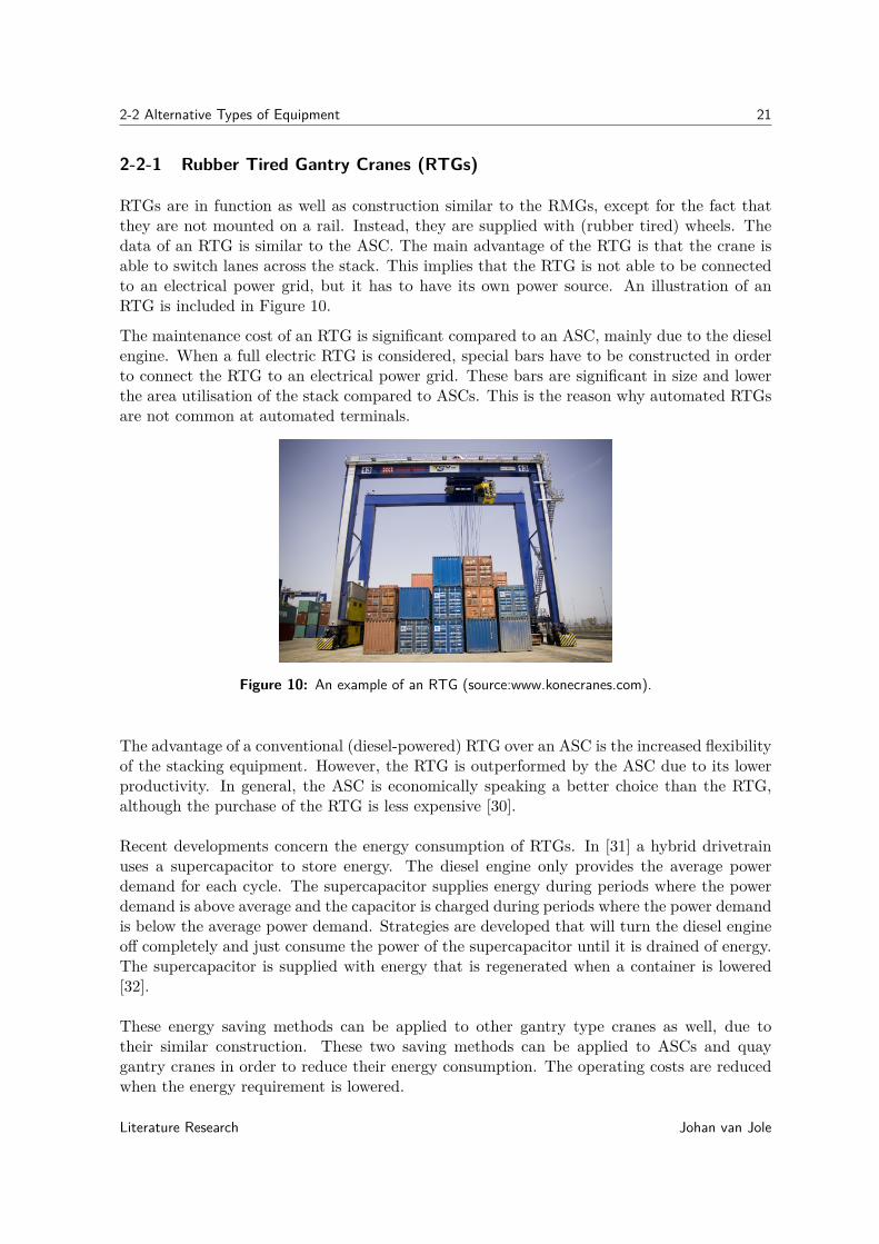
RTGs are in function as well as construction similar to the RMGs, except for the fact thatthey are not mounted on a rail. Instead, they are supplied with (rubber tired) wheels. Thedata of an RTG is similar to the ASC. The main advantage of the RTG is that the crane isable to switch lanes across the stack. This implies that the RTG is not able to be connectedto an electrical power grid, but it has to have its own power source. An illustration of anRTG is included in Figure 10.
The maintenance cost of an RTG is significant compared to an ASC, mainly due to the dieselengine. When a full electric RTG is considered, special bars have to be constructed in orderto connect the RTG to an electrical power grid. These bars are significant in size and lowerthe area utilisation of the stack compared to ASCs. This is the reason why automated RTGsare not common at automated terminals.
Figure 10: An example of an RTG (source:www.konecranes.com).
The advantage of a conventional (diesel-powered) RTG over an ASC is the increased flexibilityof the stacking equipment. However, the RTG is outperformed by the ASC due to its lowerproductivity. In general, the ASC is economically speaking a better choice than the RTG,although the purchase of the RTG is less expensive [30].
Recent developments concern the energy consumption of RTGs. In [31] a hybrid drivetrainuses a supercapacitor to store energy. The diesel engine only provides the average powerdemand for each cycle. The supercapacitor supplies energy during periods where the powerdemand is above average and the capacitor is charged during periods where the power demandis below the average power demand. Strategies are developed that will turn the diesel engineoff completely and just consume the power of the supercapacitor until it is drained of energy.The supercapacitor is supplied with energy that is regenerated when a container is lowered[32].
These energy saving methods can be applied to other gantry type cranes as well, due totheir similar construction. These two saving methods can be applied to ASCs and quaygantry cranes in order to reduce their energy consumption. The operating costs are reducedwhen the energy requirement is lowered.
Literature Research Johan van Jole
22 Equipment at Automated Container Terminals
2-2-2 Overhead Bridge Cranes (OBCs)
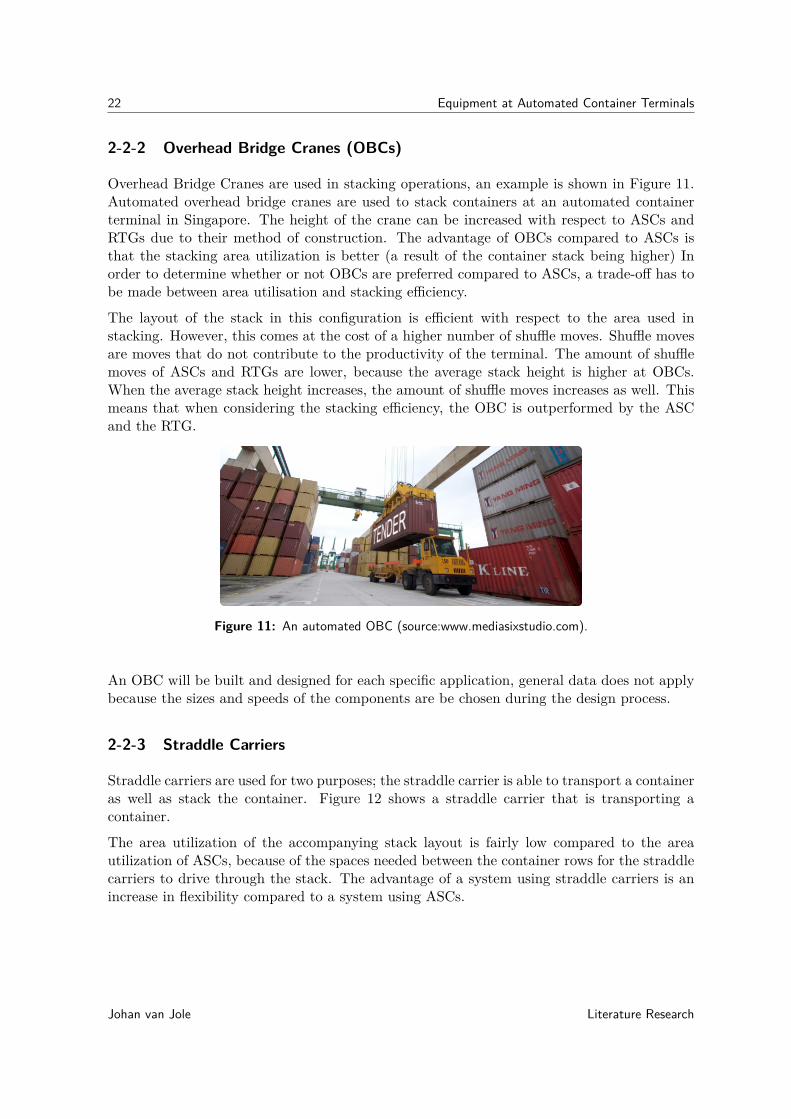
Overhead Bridge Cranes are used in stacking operations, an example is shown in Figure 11.Automated overhead bridge cranes are used to stack containers at an automated containerterminal in Singapore. The height of the crane can be increased with respect to ASCs andRTGs due to their method of construction. The advantage of OBCs compared to ASCs isthat the stacking area utilization is better (a result of the container stack being higher) Inorder to determine whether or not OBCs are preferred compared to ASCs, a trade-off has tobe made between area utilisation and stacking efficiency.
The layout of the stack in this configuration is efficient with respect to the area used instacking. However, this comes at the cost of a higher number of shuffle moves. Shuffle movesare moves that do not contribute to the productivity of the terminal. The amount of shufflemoves of ASCs and RTGs are lower, because the average stack height is higher at OBCs.When the average stack height increases, the amount of shuffle moves increases as well. Thismeans that when considering the stacking efficiency, the OBC is outperformed by the ASCand the RTG.
Figure 11: An automated OBC (source:www.mediasixstudio.com).
An OBC will be built and designed for each specific application, general data does not applybecause the sizes and speeds of the components are be chosen during the design process.
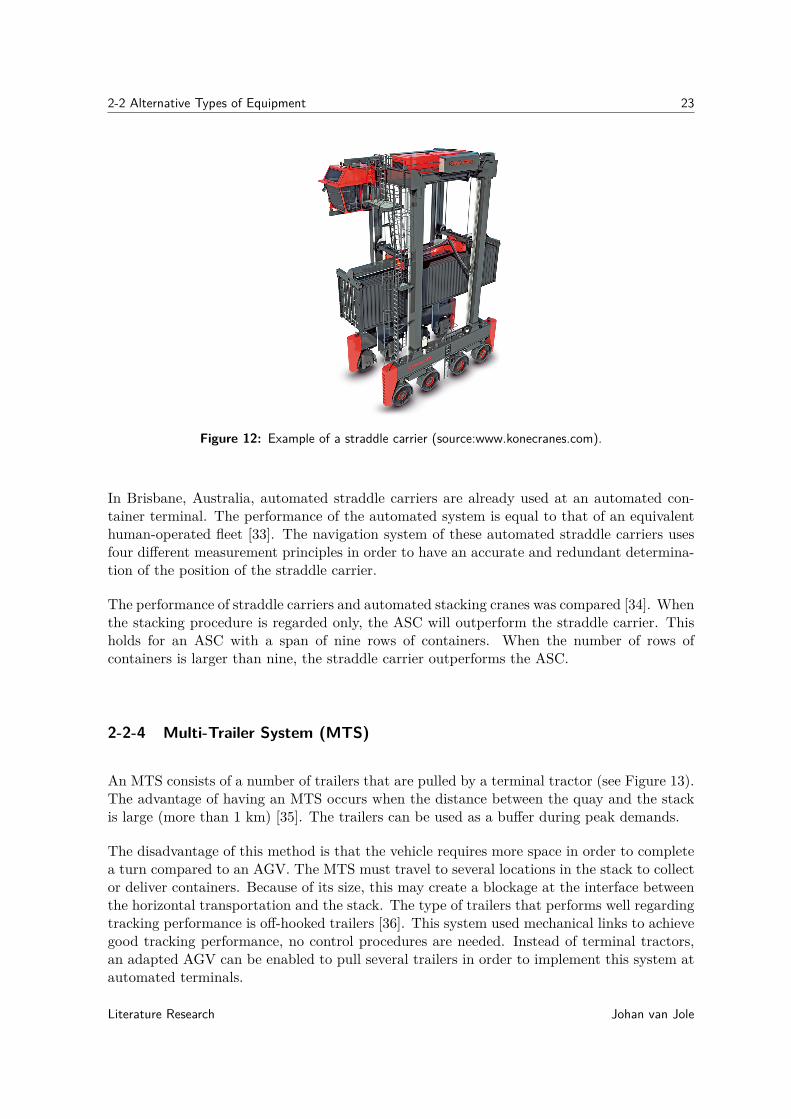
2-2-3 Straddle Carriers
Straddle carriers are used for two purposes; the straddle carrier is able to transport a containeras well as stack the container. Figure 12 shows a straddle carrier that is transporting acontainer.
The area utilization of the accompanying stack layout is fairly low compared to the areautilization of ASCs, because of the spaces needed between the container rows for the straddlecarriers to drive through the stack. The advantage of a system using straddle carriers is anincrease in flexibility compared to a system using ASCs.
Johan van Jole Literature Research
2-2 Alternative Types of Equipment 23
Figure 12: Example of a straddle carrier (source:www.konecranes.com).
In Brisbane, Australia, automated straddle carriers are already used at an automated con-tainer terminal. The performance of the automated system is equal to that of an equivalenthuman-operated fleet [33]. The navigation system of these automated straddle carriers usesfour different measurement principles in order to have an accurate and redundant determina-tion of the position of the straddle carrier.
The performance of straddle carriers and automated stacking cranes was compared [34]. Whenthe stacking procedure is regarded only, the ASC will outperform the straddle carrier. Thisholds for an ASC with a span of nine rows of containers. When the number of rows ofcontainers is larger than nine, the straddle carrier outperforms the ASC.
2-2-4 Multi-Trailer System (MTS)
An MTS consists of a number of trailers that are pulled by a terminal tractor (see Figure 13).The advantage of having an MTS occurs when the distance between the quay and the stackis large (more than 1 km) [35]. The trailers can be used as a buffer during peak demands.
The disadvantage of this method is that the vehicle requires more space in order to completea turn compared to an AGV. The MTS must travel to several locations in the stack to collector deliver containers. Because of its size, this may create a blockage at the interface betweenthe horizontal transportation and the stack. The type of trailers that performs well regardingtracking performance is off-hooked trailers [36]. This system used mechanical links to achievegood tracking performance, no control procedures are needed. Instead of terminal tractors,an adapted AGV can be enabled to pull several trailers in order to implement this system atautomated terminals.
Literature Research Johan van Jole

24 Equipment at Automated Container Terminals
Figure 13: Example of an MTS system at the ECT terminal (source:www.brandigg.de).
2-2-5 Rail-Mounted Automated Guided Vehicles (RGVs)
Rail-Mounted Guided Vehicles (RGVs) are similar to AGVs, but for the propulsion system.The vehicles are mounted on rails and they are driven by a series of electromagnets [37].
The advantage of RGVs is that the control procedures are relatively simple when comparedto AGVs. The RGV is only able to follow the rail, and control of motion becomes onedimensional. Because the uncertainties with respect to the actual position of RGVs are lessthan the uncertainties that are associated with AGVs, the spacing between two vehicles canbe reduced. This means that a higher capacity can be achieved.
The reason that this approach is not used at container terminals is that in case of a failureof a single vehicle, the whole terminal transportation system fails. A queue of RGVs willform behind the broken RGV. AGVs do not have this problem, because they are able to drivearound a vehicle that is broken down.
Like the AGVs, the RGV-system is completely automated. Position control is relativelysimple, it is relatively easy to measure and effect the position of the vehicle. The concept ofRGVs to be deployed at container terminals is illustrated in Figure 14.
Johan van Jole Literature Research

2-3 Conclusion 25
Figure 14: Impression of an RGV system at a container terminal (source:www.metrans.org).
2-3 Conclusion
The frequently used types of equipment are the AGVs, ASCs, RMGs and quay cranes. Thesetypes of equipment are already used at automated container terminals. Other types of equip-ment are in place as well, although not all types are ready for implementation at automatedcontainer terminals yet. It is possible to automate the alternative types of container han-dling equipment as well. These types of equipment can subsequently be used at automatedcontainer terminals at which the frequently used types of equipment are unfavorable.
Because the majority of container terminals all use the four frequently used types of containerhandling equipment, this report will focus on these four types in the subsequent chapters. Inorder to automate the container terminal, these four types of equipment need to cooperate inorder to handle the containers in the best possible way.
Tables 7, 8 and 9 show the main strengths and weaknesses of the different pieces of equipment.
Literature Research Johan van Jole

26 Equipment at Automated Container Terminals
Table 7: Comparison between ASCs and straddle carriers
Equipment Strengths WeaknessesASC better yard utilization compared to
straddle carrierhigh investment costs compared tostraddle carriers
straddle car-rier
high degree of flexibility low area utilization of stack lay-outdue to the space needed for thestraddle carrier to drive through thestack
Table 8: Comparison between RMGs, RTGs and OBCs
Equipment Strengths WeaknessesRMG relatively easy to automate high investment costs compared to
RTGs (higher purchase price, costof creating rails at the terminal)
RTG high degree of flexibility, relativelylow investment costs
relatively high maintenance costs,RTG cannot be connected to energysupply grids
OBC high stacking area utilization com-pared to RMGs or RTGs
reduced stacking efficiency com-pared to RMGs or RTGs
Table 9: Comparison between AGVs, RGVs and Multi Trailer Systems
Equipment Strengths WeaknessesAGV high degree of flexibility complex control procedures com-
pared to other solutionsRGV simplified control procedures com-
pared to AGVsfailure sensitive, in case one compo-nent fails the system stops working
MTS most efficient transport mechanismwhen distance between quay andstack is over 1 km
vehicle requires more space to drivecompared to other solutions
Johan van Jole Literature Research

Chapter 3
Control of Individual AGVs
The previous chapter concerned the types of equipment used at automated containerterminals. The most frequently used type of equipment for horizontal transportationat automated container terminals is the AGV. This chapter emphasizes the control ofindividual AGVs. The first section discusses the architecture of the AGV along with thecontrolled basic variables of the AGV. The second section covers the types of localisationprocedures that can be used on AGVs. The third section discusses the models that areused by controllers to control the individual AGVs. The fourth section discusses themethods that are used to increase the energy efficiency of the AGV. The final sectionconcludes this chapter with a summary. After the needs of the individual AGV controlleris determined, control of AGVs at a system level is discussed in the next chapter.
The goal of a controller of an AGV is to complete the transportation task that will be assignedby the AGV system controller. A transportation task is an order to transport a containerbetween the stack and the cranes handling the trains and vessels.
In order for the controller to be able to reach its goal, it must measure and actuate severalvariables. The next section gives an overview of these variables.
3-1 The Architecture of an AGV
A general description of an AGV (including the specification of an AGV used at containerterminals) is given in Chapter 2. The detailed architecture of the AGV is outlined in thissection. The AGV consists of several subsystems; chassis, suspension, drivetrain, electronicsand energy storage. These subsystems are covered along with their basic measured and actuatedvariables.
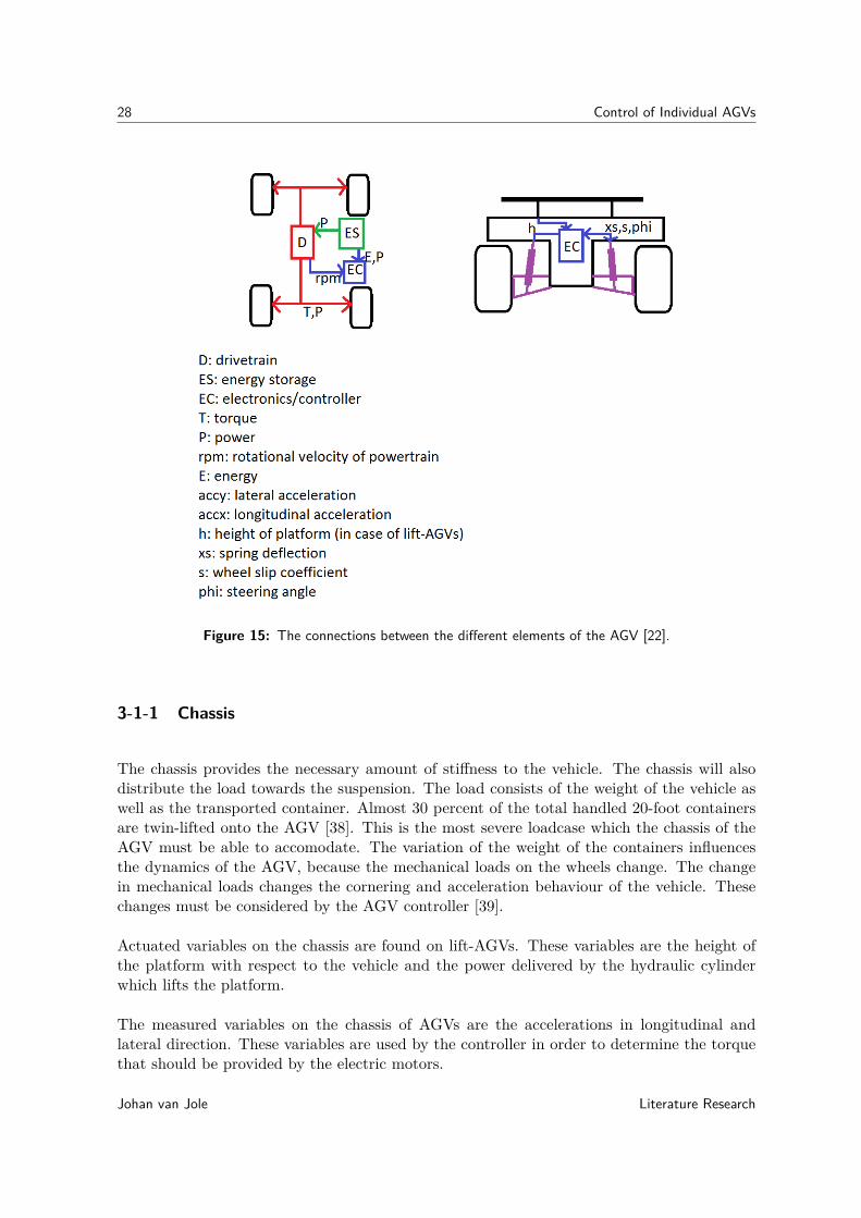
The connections between the different elements are shown in Figure 15. The variables thatare exchanged are labeled at the connections.
Literature Research Johan van Jole
28 Control of Individual AGVs
Figure 15: The connections between the different elements of the AGV [22].
3-1-1 Chassis
The chassis provides the necessary amount of stiffness to the vehicle. The chassis will alsodistribute the load towards the suspension. The load consists of the weight of the vehicle aswell as the transported container. Almost 30 percent of the total handled 20-foot containersare twin-lifted onto the AGV [38]. This is the most severe loadcase which the chassis of theAGV must be able to accomodate. The variation of the weight of the containers influencesthe dynamics of the AGV, because the mechanical loads on the wheels change. The changein mechanical loads changes the cornering and acceleration behaviour of the vehicle. Thesechanges must be considered by the AGV controller [39].
Actuated variables on the chassis are found on lift-AGVs. These variables are the height ofthe platform with respect to the vehicle and the power delivered by the hydraulic cylinderwhich lifts the platform.
The measured variables on the chassis of AGVs are the accelerations in longitudinal andlateral direction. These variables are used by the controller in order to determine the torquethat should be provided by the electric motors.
Johan van Jole Literature Research

3-1 The Architecture of an AGV 29
3-1-2 Suspension
The suspension distributes the load from the chassis onto the wheels. This system consistsof springs, linkages (to connect the chassis and the wheels) and dampers. The suspensionmakes sure that the wheels remain in contact with the ground.
The geometry of the suspension system comes in many different forms. Double-wishbone,McPherson struts, trailing arms, swing-axles, beam-axles and multi-link suspensions are com-mon used geometry concepts. McPherson struts are applied to AGVs, creating suspensionkinematics that support four wheel steering. Figure 16 shows the concept of a McPhersonstrut suspension. The measured variables on the suspension of an AGV are spring deflections
Figure 16: Concept of a McPherson strut suspension (source:en.wikipedia.org)
and wheel slip. The spring deflection is used to calculate the normal loads on the wheelsof the vehicle. The spring deflection is also used in order to determine the weight of thecontainer that is transported. These variables are important when a dynamic model of thevehicle is used by the controller in order to determine the torque that should be deliveredto the wheels. The wheel slip variable serves to calculate the required steering angle for theAGV.
The actuated suspension variable is the steering angle of the AGV. The AGV has symmetricalfour wheel steering. The steering angle at the front of an AGV is equal to the steering angleat the back of that AGV. In order to be able to increase the velocity while cornering thevehicle Ackermann steering is applied, which can be provided with a mechanical linkage [40].
3-1-3 Drivetrain
The drivetrain consists of the motor (also called powertrain) that delivers a drive torque andthe elements which transmit the torque and power to the wheels (such as gears and axles).The AGV has electric motors, which are powered by a battery or a diesel-driven generator.These motors can be placed inboard as well as outboard.
Literature Research Johan van Jole

30 Control of Individual AGVs
Inboard electric motors need to be connected to the wheel by means of a driveshaft. Withinboard motors it is possible to drive two wheels using one motor. Outboard electric motorsare directly coupled to the wheels; the disadvantage of this method is the increased unsprungmass of the vehicle. The advantage is that the torque supplied to each wheel can be controlledseperately.
The actuated variables of the drivetrain are the torque of the electric motors and the powerthat is supplied by these motors. The variables that is measured is the rpm of the electricmotors. This variables is used by the controller to calculate the velocity of the AGV aftercorrection for wheel slip.
3-1-4 Energy Storage
The energy storage delivers energy to the drivetrain. The energy storage is either a fuel tank(for diesel powered AGVs) or a battery pack (for electric powered AGVs). Electric power isadvantegeous because the other types of equipment used on container terminals are drivenelectrically as well.
The measured variables of the energy storage is the amount of energy that is left as well asthe rate of usage of electric power. The controller uses this information in order to determinewhether or not the battery should be recharged.
3-1-5 Electronics
The electronics on the vehicle processes the measurements and accounts for computing theactions that should be performed on the vehicle. The communication systems are a part of theelectronics that are located on the vehicle. The electronic system consists of the controllers,sensors, actuators and the wiring linking these components.
Except for the variables that are already presented in this section, the electronics obtaininformation on the transportation task as well. Information on the transported container andthe trajectory of the AGV are received from the AGV system controller.
The information on the trajectory of the AGV is used as a reference, in order to be able todetermine the drive and steering commands. The commands are calculated by evaluation ofa model describing the behaviour of the vehicle.
3-2 localisation Methods for AGVs
localisation systems are important in AGVs. The function of the localisation system is todetermine the location of the AGV. The AGV controller uses the location and velocity ofthe AGV to determine the required heading and velocity of the vehicle. This section coversdifferent localisation principles used on AGVs.
Johan van Jole Literature Research

3-2 localisation Methods for AGVs 31
Table 10 lists the different types of localisation principles. There are two types of localisationmethods, on-board and outboard localisation. When an on-board localisation system is used,the vehicle is able to determine the location and velocity without communication with externalsystems. Outboard localisation methods communicate with seperate systems in order to locatethe vehicle. One off-board localisation method consists of a wire buried below the surface
Table 10: Several types of localisation principles
localisation method measuring principle type of systemburied wires doppler-effect off-boardcolored tape difference in reflectance off-boardgyroscope resistance against change in
rotational velocity of spinningwheel
on-board
radar reflectance of radio waves onforeign objects
on-board
optical systems image processing software on-boardGPS triangulation on-boardwheel encoders rotational velocities on-board
transmitting a radio signal. A sensor on the AGV is able to determine the distance betweenthe AGV and the radio signal. The position of the AGV relative to the wire is known. Thelocation of the wire is known to the AGV, so the position of the AGV can be calculated.
The same concept can also be applied using colored tape on the ground, this is also an off-board method. The position of the AGV with respect to the tape can be determined usinga camera or a set of light diodes. These localisation principles create an AGV system thatlacks flexibility; hence these methods are not used at container terminals anymore.
On-board localisation on the AGV can be performed using gyroscopes. The gyroscope is ableto detect even the slightest deviation in heading of the vehicle. The gyroscopes that are inuse are electrostatic gyroscopes and the floated gyroscope, both having a high accuracy. Theaccuracy is measured by the value of random drift, which is the amount of degrees shift peroperating hour. High accuracy systems have a random drift below 0.001 degree/hour [41].Research is done at new gyroscopes, for instance the ring laser gyroscopes, the hemisphericalresonator gyroscope and the MEMS-gyroscope. The accuracy of the gyroscopes is alreadysufficient for implementation on the AGV running on a container terminal.
Another on-board localisation method is radar. The vehicle sends a signal and determineshow long it takes for the signal to return to the vehicle. The distance towards several objectscan be calculated by multiplying the travel time of the signal and the velocity of the signal.High precision systems with an operational range of 10 m. and a sampling period of severalmilliseconds are designed for localisation of indoor vehicles [42]. This system can be expandedfor use outdoor as well by magnifying the operational range. Radar systems are also able toidentify obstacles.
Literature Research Johan van Jole
32 Control of Individual AGVs
Optical systems are able to be used in on-board localisation procedures. In this case, theimage processing software on the AGV is supplied with images from cameras placed on thevehicle. The software is able to determine the distance to reference points in order to locate thevehicle. Obstacles and the distance to the obstacles can be determined as well. This methodis already applied at indoor AGVs; this system is able to achieve a good tracking performance[43]. The architecture of the system is completely different compared to architecture that isused on outdoor AGVs. The outdoor AGVs need to be modified in order to be able to usethis system.
Triangulation procedures are well-known examples of on-board localisation. One famousexample is GPS, where at least three signals from satellites are used to determine the locationof the vehicle. The signals can also be sent from several fixed points on the terminal. Thedistance from the receiver to the sender is determined by the Doppler phase-shift of the signal.The location accuracy depends on the receiver that is used and atmospheric effects. With theuse of augmentation systems, accuracy of a few centimeters can be realized [44].
The European Union is currently involved in the process of creating a similar system withan even greater accuracy [45]. Unlike GPS or GNSS (A similar system developed by Russianauthorities), which are military services; the European service will be under civilian control.
The disadvantage of GPS is that the signals can be subject to interference due to the presenceof large obstacles at the container terminal. These obstacles are cranes, containers etc. [33].
The last on-board localisation method uses wheel encoders [39], these sensors measure therotating velocity of the wheels. A separate sensor measuring the tire slip has to be incorpo-rated as well, because the slip ratios of rubber tires are significant. When tire slip cannot becorrected for, this method is very inaccurate and cannot be used on AGVs.
The wheel encoders, radar, gyroscope and GPS systems are most suitable for use in AGVs[33]. The AGVs do not have to follow predefined lanes, making the AGV system flexible.The methods are accurate enough for implementation. Several different types of localisationmethods can be used to provide redundancy in order to avoid failures of the localisationsystem.
Table 11 shows the strenghts and weaknesses of the aforementioned localisation methods.
Johan van Jole Literature Research

3-3 Models Used to Control AGVs 33
Table 11: Comparison of different localisation methods
Localisationmethod
Strenghts Weaknesses
Buried wires relatively inexpensive, simpleto construct
AGV system becomes inflexi-ble
Colored tape relatively inexpensive, simpleto construct
AGV system becomes inflexi-ble
Gyroscope Accurate Relatively expensiveRadar Well-developed technology Subject to interference ef-
fects from for instance com-munication equipment, elec-tric equipment etc.
Optical systems Method can be used for colli-sion avoidance as well
Relatively expensive softwareand hardware
GPS Proven technology, relativelyinexpensive
Potential interference effectsfrom large obstacles
Wheel encoders Relatively inexpensive Complicated control proce-dures are needed to make thismethod accurate enough
3-3 Models Used to Control AGVs
The previous section presents localisation techniques that are used to locate the vehicle. To-gether with the planned path this forms the most important input to the AGV controller. Thenumber of other inputs that are required depends on the control method that is used. Themodels that are used to control AGVs are kinematic models and dynamic models.
The AGV is provided with the information on where it is planned to be. This information iscompared with the actual location of the AGV and the deviation is calculated. This deviationis an important control criterion, because the AGV must be positioned accurately enough inorder for the cranes to lower a container on the vehicle (or lift the container from the vehicle)
The required velocity of the AGV is often calculated by a controller using a kinematic model.A kinematic model only considers the motions (displacements, velocities and accelerations)of the vehicle. The variables of the kinematic model are acceleration, velocity, distance andtime and these are used in order to calculate the reference velocity of the AGV.
Figure 17 shows the system and control cycle for the controllers using a kinematic model.The kinematic model is implemented in the controller in order to determine the actions thatshould be performed by the AGV. The system and control cycle represents the method ofcontrolling the system. Measurements are performed on the system and subsequently fed intothe controller. The controller then calculates the required actions that should be performedon the system. This process is then repeated until the goal is reached.
The state of the AGV consists of the position, velocitiy and heading. These variables aremeasured on the AGV. The actions that can be performed are applying a drive torque to thewheels or change the heading of the vehicle.
Literature Research Johan van Jole

34 Control of Individual AGVs
Figure 17: System and control cycle for kinematic models.
A controller using fuzzy logic is able to reduce the tracking error (deviation of current statefrom the desired state) [46]. The controller in this paper outperformed PID-control of theAGV. The reason for this is that an increase in load on the AGV led the PID control toperform badly whereas the fuzzy control was unaffected.
The PID as well as the fuzzy logic controlled AGVs only measure the position of the AGV inorder to calculate the required control actions. The actuated variables on the AGV are thepower delivered to the drives as well as the steering angle of the AGV.
When the AGV is travelling at high speeds, vehicle dynamics play a vital role in the handling,vehicle stability and performance of the AGV. Therefore, a model incorporating the dynamicsof the vehicle in order to calculate the actions of the AGV is developed [39]. A dynamic modelis a study on the interaction between forces and motions. This dynamic model is implementedin the controller in order to determine the actions by evaluating the states. With the useof a vehicle dynamics model (a model describing the transient behaviour of the AGV) ofthe AGV it is possible for the AGV to travel at high velocities while keeping the trackingerror to a minimum. A dynamical model is different with compared to a kinematic model.Kinematic models consider the motions of the system under study. Dynamic models considerthe interaction of the forces that are applied to the system.
The information need of the controller increases when vehicle dynamics models are imple-mented; the position of the AGV, the rotational velocities of the wheels, change of heading,the accelerations along the longitudinal and lateral axis of the vehicle, steered angle of allwheels and wheel slip need to be known. An estimate for the maximum tire-road frictioncoefficient needs to be provided as well.
The tire forces are calculated at vehicle dynamics models. A simple linear tire model can pro-vide a good approximation of the tire forces (when they are not in saturation). This model issuited for implementation in a controller. The nonlinear "Magic Formula" tire model (devel-oped by Pacejka) is an exact model describing tire loads. However, due to the model beingnonlinear it is not suited for implementation in real time control and a linear approximationof this model is implemented in controllers.
Johan van Jole Literature Research

3-3 Models Used to Control AGVs 35
Torque vectoring can be applied to the AGV using the output of the vehicle dynamics model.The drive torques provided to all wheels differ in order to maximize the traction forces thatcan be generated by the tires. The tire model is used to calculate the magnitude of theserequired drive torques.
Dynamical models can be implemented in MPC-structures. MPC stands for model predictivecontrol, the MPC controller is able to optimize the current timestep while taking futuretimesteps into account. A fixed number of timesteps are evaluated at each interval, the MPCcontroller uses a fixed planning horizon. The advantage of this method of control is that isable to anticipate on the events within the planning horizon when determining the action forthe current timestep.
The AGV is able to check for obstacles that are not accounted for by the path and trajectoryplanning procedures. The method described in [47] can be used in order to avoid obstacles.The path that was generated by the traffic control system is a large attractive potential, sothe AGV follows this path. When an object is spotted, there is a repulsive potential, leadingthe AGV away from the object. Once the AGV has passed the object, it will continue alongthe originally planned path. Information regarding eventual obstacles can be obtained byradar or laser range finders.
The AGV controller has to make sure the boundary conditions, like the maximum velocity ofthe vehicle, are not violated.
Table 12 shows the strengths and weaknesses of the diffent control methods that are in useto control the AGVs
Table 12: Comparison of different AGV control methods
Control methods Strenghts WeaknessesKinematic models Relatively simple method
compared to vehicle dynamicsmodelling
Method is not able to achievehigher velocities of the AGV
Fuzzy logic Control method is able toachieve satisfactory perfor-mance regardless of weightcontainer and velocity of AGV
Method is not able to achievehigher velocities of the AGV
PID control Well-developed technology Large changes in the variables(weight of container) causesthis method to perform poorly
Controller usingVehicle Dynamicsmodelling
Control method able toachieve relatively high ve-locities of the AGV, enablestorque vectoring
Relatively complex methodcompared to the other meth-ods
Literature Research Johan van Jole
36 Control of Individual AGVs
3-4 Energy Efficiency of AGVs
This section presents the methods used to increase the energy efficiency of the AGVs. Thesemethods can be implemented in the control procedures.
With electric powered AGVs, it is possible to implement regenerative braking. Regenerativebraking recovers the kinetic energy of the vehicle when it’s braking. Under braking, electricmotors will operate as brakes, slowing the vehicle down. While these motors operate as brakes,they generate electric energy, which can be stored by means of batteries, super capacitors [31]or by driving a flywheel [32].
The advantage of supercapacitors is that the power density is higher compared to batteries.Supercapacitors can be charged and discharged faster than batteries. The energy density ofsupercapacitors is smaller than batteries, therefore supercapacitors are used alongside batter-ies to store the regenerated energy only [48]. Flywheel systems add a significant amount ofmass. The power density (in W/kg) of a flywheel is in the same order of magnitude as thesupercapacitors while the energy density (Wh/kg) is significantly greater [49].
The recovered energy can be used when the vehicle accelerates again. The recovered energyis used in order to power a part of the energy peak that is required at acceleration, increasingthe energy efficiency. Four-quadrant motors (also called motor-generators) can be connectedto the wheels in order to drive and brake the AGV by means of the same devices.
Another configuration is having a separate drive (for instance a diesel engine connected tothe wheels by means of a transmission) and connecting an electric motor to the drive shaftsin order to provide extra power during peak demands. The main advantage is that the dieselengine can operate at its most efficient operating point. The complexity of the system andthe controller will increase significantly, so this configuration is generally not preferred.
The AGV will experience a reduced amount of drag when travelling at a lower velocity. Itis therefore beneficial to drive as slow as possible with respect to the energy efficiency ofthe equipment. However, the container handling performance cannot be compromised. Thismeans that the AGVs should travel as slow as possible without becoming a bottleneck in thecontainer handling process [50]. This method can be retrofitted to an existing fleet of AGVsand does not require the installation of extra components on the AGV.
Table 13 contains the comparison between the different energy saving methods.
Johan van Jole Literature Research

3-4 Energy Efficiency of AGVs 37
Table 13: Comparison of different energy saving methods for AGVs
Energy recoverymethod
Strenghts Weaknesses
Flywheel High power density System adds to the complex-ity of the AGV architecture
Supercapacitorbank
High power density Low energy density
Batteries In current situation alreadyinstalled at AGVs
The mass of batteries neededto store sufficient amounts ofenergy is significant
Hybrid drive-trains
Diesel engine can be operatedat its most efficient operatingpoint
System adds to the complex-ity of the AGV architecture
Minimize thevelocities of theAGVs
Method does not require in-stallation of extra compo-nents, can be retrofitted to ex-isting fleet of AGVs
The AGVs need to be coordi-nated well in order to fulfill alltransportation tasks on time
Literature Research Johan van Jole

38 Control of Individual AGVs
3-5 Conclusion
The architecture of individual AGVs and their relations are considered in this chapter. Thelocalisation methods are discussed in this chapter as well. The performance of the AGV isinfluenced by the accuracy of the localisation method that is used in order to measure thelocation and velocity of the AGV.
The mainstrain ways for localisation of AGVs are radar, gyroscopic systems, GPS systemsand wheel encoders. Several of these measuring principles are used simultaneously in orderto provide redundancy in case one sensor fails.
The most suited modelling method for AGVs is the method of dynamical modelling the AGV.The relation between the drive force and the velocity of the AGV is modeled. Dynamicalmethods are therefore better than kinematic models that estimate the required drive force byevaluating the motions of the AGV.
Dynamical modelling accounts for higher velocities of the vehicles, which can increase theproductivity of the AGV system. The productivity is increased because a larger numberof boxes can be transported in the same amount of time. A fuzzy control implementationis suited to control the AGV when the velocities are relatively low. The AGV is not ableto achieve high velocities, contrary to an AGV utilizing a controller which makes use of adynamical model of the AGV.
Torque vectoring and regenerative braking are used in order to increase the performance ofthe AGV and reduce the energy requirements of the AGV. Torque vectoring is used to supplyonly the necessary amount of power to each wheel, regenerative braking is used to recoverthe kinetic energy when the AGV is slowing down.
There are still open problems that need to be adressed in the future AGVs are nowadayspowered electrically, electric AGVs have the potential to recover the kinetic energy at brakingevents. There are few papers on energy recovery at AGVs, while the possible gains are largedue to the large mass that is accelerated and decelerated. Research should be performedin order to assess which of the energy saving methods is best suited for implementation onAGVs.
Also, applications of vehicle dynamics models at AGVs are not listed in literature, this is anopen problem which needs to be adressed. The potential gain is an increase in the velocity ofthe AGV, which implies that less AGVs are needed at container terminals compared to thecurrent situation. In order to calculate the wheel loads in the vehicle dynamics models, thecenter of gravity needs to be known, based on this survey one method is designed which isable to do this. This method is explained in Appendix A.
Johan van Jole Literature Research

Chapter 4
Control of AGVs From a ContainerTerminal Perspective
The previous chapter provided an outline into the control of individual AGVs. At auto-mated container terminals, there are a number of AGVs performing transportation tasks.The movements of these AGVs need to be coordinated in order to make sure that allcontainers are transported and the AGVs do not collide with each other. Coordination ofthe movements is performed at a system level, where the system consists of the entire fleetof automated guided vehicles. The first section covers the dispatching of the AGVs. Thesecond section spans the trajectory planning as well as avoidance of collisions betweenAGVs. The third section considers the link between the individual AGV controllers andthe AGV system level controller, before heading to the conclusion in the final section.
The goal of controlling the fleet of AGVs is to coordinate the motions of the AGVs as wellas distributing the transportation tasks evenly across the entire fleet of AGVs. The controlprocess of the system of AGVs contains three elements: dispatching, trajectory planning andcollision avoidance.
The relation between the different processes is outlined in Figure 18. Typically, the AGVsystem control architecture consists of the dispatching controller and a trajectory planningcontroller.
Literature Research Johan van Jole

40 Control of AGVs From a Container Terminal Perspective
Figure 18: Schematic representation of the different levels of control.
The dispatching controller assigns a vehicle to a transportation task. Typically, the dispatch-ing procedure provides the locations that the AGV should drive to in order to collect anddeliver a container [47]. After the AGV is assigned to a transportation task, the route iscalculated by the trajectory planning process. The trajectory planning process calculates theroute of the AGV in two stages. First, the trajectory from the current position towards thepick-up location of the container needs to be calculated. Subsequently, the trajectory betweenthe pick-up and drop-off location is calculated.Collision avoidance is a very important issue with autonomous vehicles; the AGVs must stayclear of each other as well as obstacles. The information from the trajectory planning phaseis used in order to detect collisions of paths of several AGVs, which are subsequently resolved.Collision avoidance is considered being a part of the trajectory planning process. Due to itsimportance to container terminals, it is explicitly mentioned in this chapter.These processes are covered in detail in the next sections. The processes are covered fromthe top level to the lower levels. This means that dispatching is discussed first before headingonto trajectory planning and collision avoidance.
4-1 Dispatching of AGVs
This section covers the dispatching of AGVs. The methods are briefly discussed here for thesake of completeness. The dispatching methods have been investigated extensively and anoverview of these studies can be found in [47]In some procedures, dispatching is preceded by scheduling [51], [52]. The goal of schedulingin this case is to minimize the turnaround time of the vessels and trains. The cranes arescheduled in order to minimize the turnaround times and the AGV system adheres to theschedule created by the cranes. The AGVs follow the transportation requests coming fromthe quay cranes, RMGs and stacking cranes. The cranes give orders to the AGV system, atransportation task is a request to transport a container to or from the crane.
Johan van Jole Literature Research

4-1 Dispatching of AGVs 41
The cranes are scheduled in order to minimize the turnaround time of the vessels and trains.This process is explained in the next chapter. In most cases the AGVs only follow theorders from the cranes, the AGVs themselves do not need to be scheduled. Another set ofapproaches exist where AGVs are scheduled. The scheduling process and the dispatchingprocess are combined in these approaches [47].
The goal of the dispatching process is to select an AGV that will conduct the transportationtask according to a specific objective (e.g. minimizing the travelled distance). A transporta-tion task is a container which needs to be moved from the origin to the destination location.For each transportation task, only one AGV must be selected among the set of AGVs thatis assigned to the vessel or train to which the transportation task belongs. The dispatchingprocess selects an idle AGV and assigns it to a transportation task. The parameter describingthe state of the vehicles (the vehicle being idle or conducting a transportation task) has thelargest influence on the outcome of the dispatching process.
Dispatching of an AGV occurs when an idle AGV is assigned a transportation task. Twokinds of dispatching problems exist: workcentre and vehicle initiated dispatching [47]. Whenthe dispatching is workcentre initiated, an AGV is selected among a set of idle vehicles.Dispatching is vehicle initiated if an AGV has to select a transportation task from a set oftransportation requests. Figure 19 shows a number of AGVs that are dispatched and aredriving towards their assigned transportation task.
Figure 19: Dispatched AGVs driving towards their task (source: www.demagcranes.fr)
Dispatching of AGVs is performed according to rules. Currently there are several rules inexistence that are used on terminals. These rules are listed in Table 14 [47].
Literature Research Johan van Jole

42 Control of AGVs From a Container Terminal Perspective
Table 14: Overview of different dispatching rules.
type of dispatch-ing rule
dispatching rule goal of the dispatching rule
workcentre initiated random vehicle rule distribute transportation tasksevenly
workcentre initiated nearest vehicle rule minimizing total travelled distanceworkcentre initiated farthest vehicle rule minimizing idle time of the AGVsworkcentre initiated longest vehicle idle time
ruledistribute transportation tasksevenly
workcentre initiated least utilized vehiclerule
distribute transportation tasksevenly
vehicle initiated random workcentre rule distribute transportation tasksevenly
vehicle initiated shortest travel time rule minimizing total travel timevehicle initiated shortest distance rule minimizing total travelled distancevehicle initiated maximum outgoing
queue sizeprevent blockages at parts of theterminal
A multi-attribute rule combines several dispatching rules [47]. A multi-attribute rule considersseveral criteria; for instance the unloaded travel distance of the AGV to the pick-up point,the remaining space in the buffers at the pick-up and delivery points and the idle time of thevehicle. Each criterion is assigned a weight which changes depending on the current statusof the system. It has been shown that this kind of rule performs better than single-attributerules or multi-attribute rules with fixed weights.It has been determined that workcentre initiated dispatching outperforms vehicle initiateddispatching when container terminals are considered [47]. Performance increases when thedispatching controller is supplied with pre-arrival information of transportation requests. Thedispatching controller is able to assign a vehicle before the transportation task becomes avail-able. The vehicle in the mean time is able to drive up to the pick-up location. This isimportant at quay cranes, because the AGV needs to be at the crane as the container islowered in order to enable the crane running at its maximum capacity.Fuzzy logic, neural networks and Markov decision processes hardly outperform heuristic rules.This makes that in the dispatching controller of an AGV system heuristic rules are most oftenapplied.Another distinction in dispatching processes exists: off-line or on-line dispatching. Off-linemethods use the information at the start of the transportation processes in order to assign theAGVs to the tasks in an optimal manner. All transportation requests at a container terminalare not known in advance, that is why an on-line method to schedule the AGVs is preferred inmost cases. On-line methods are able to assign vehicles when transportation requests becomeavailable, allowing for more scheduling flexibility.The dispatching of AGVs at container terminals is workcentre initiated. The AGVs aredispatched by applying heuristic decision rules which are able to select the AGV which isbest suited to fulfill the transportation task. The AGV that is best suited to fulfill thistransportation task can be the AGV that is closest to the pick-up location or the AGV thatis least utilized (as is already displayed in Table 14).
Johan van Jole Literature Research

4-2 Trajectory Planning and Collision Avoidance 43
4-2 Trajectory Planning and Collision Avoidance
Once the AGV is dispatched as described in the previous section, it has to be determined howto get from the pick-up to the delivery location. The trajectory that the AGV has to executeneeds to be calculated. Several methods exist already which are capable of doing so. Thissection gives an overview of several methods that are able to plan the trajectory of an AGV.Collision avoidance procedures are often integrated in the trajectory planning process, theseare discussed in this section as well. This section is divided into the subsections distributedcontrol and centralized control.
The trajectory of the AGV is calculated in two steps. The path planning procedure pro-vides a path that is optimized to some criterion (for instance: minimizing the total lengthof the path). The path spans from the current location of the vehicle via the pick-up pointto the destination point of the container. The trajectory planning procedure provides theschedule of the movement of the AGV along the planned path.
Table 15 shows an overview of different trajectory planning methods. There is a distinc-tion between centralized and distributed control. Distributed control is a control structureat which each AGV plans its own trajectory. Control of the system of AGVs is in this caseperformed by the AGVs themselves. The AGVs communicate with each other in order tocalculate the trajectories and to prevent collisions. Centralized control is a structure at whicha centralized controller determines the trajectories of all the AGVs. The central controllersends the information regarding the paths to the AGVs. The AGVs in turn send informationregarding the achieved progress of the transportation task to the central controller.
Literature Research Johan van Jole

44 Control of AGVs From a Container Terminal Perspective
Table15:
Overview
ofdifferenttrajectory
planningm
ethods.
trajectoryplanning
method
goalof
controllercontrol
structureused
model
ref.localpath
planningm
ethodlim
itchange
ofaccelerationdistributed
controlfifth
orderpolynom
ials[53]
Splittingterm
inalupinto
nodesm
inimize
thetravelled
distancedistributed
controlD
ijkstra’salgorithm
[54]zone-controlm
ethodprevent
collisionsand
deadlockscentralized
controlpartition
ofterminalinto
zones[55]
repulsive/attractivepotentials
preventcollisions
distributedcontrol
socialpedestriandynam
icm
odel[56]
petrinetsbalancing
tasksacross
thefleet
centralizedcontrol
petrinet[57]
dynamic
routingm
ethodm
inimize
travelleddistance
centralizedcontrol
kinematic
model
[58]tim
e-constrainedrouting
minim
izeenergy
requirement
centralizedcontrol
kinematic
model
[59]potentialfields
preventcollisions
distributedcontrol
potentialfields[60]
reroutingA
GVs
preventdeadlock
distributedcontrol
kinematic
models
[61]
Johan van Jole Literature Research

4-2 Trajectory Planning and Collision Avoidance 45
4-2-1 Distributed Control of AGV Systems
This subsection concerns distributed control of AGV systems. The trajectories of the AGVsare calculated by the individual AGVs. The AGVs communicate with each other in order toprevent collisions from occurring.
The local path planning algorithm tries to limit the change of acceleration in order to createa smooth ride for the AGV [53]. The velocity and curvature of the trajectory are continuousfunctions, in this case 5th order polynomials. This method is one of the first establishedmethods that enable the AGV to plan its own route.
Another distributed control method uses the Dijkstra’s algorithm in order to solve the problemof minimizing the total distance that has to be travelled by the AGV [54]. The terminal issplit up in a set of nodes. Some are fixed in order to be able to assign driving lanes. Otherswill move, like for instance the quay cranes. Every quay crane can be seen as both an origin asa destination node (depending on whether the crane is unloading or loading containers) andthese nodes are able to move along the quay wall. The shortest path between the origin anddestination nodes is calculated by Dijkstra’s algorithm. The AGV that is closest to the originnode will be assigned in order to reduce the length of the total travelled path. Dijkstra’salgorithm is used in order to obtain the optimal solution to the scheduling problem.
A method based on the social pedestrian dynamic model is also a distributed control method[56]. A repulsive potential is generated that increases when the distance between the AGVand the other AGVs (or other obstacles) becomes smaller. Points of interest (like checkpoints)provide a attractive potential in the same way. The AGVs are able to drive around each otherby evaluating the potential functions that are programmed in the controllers of the AGVs.
Potential fields (a virtual field consisting of attractive and repulsive forces) are also used inorder to avoid obstacles [60]. This control method is also a distributed approach towardstrajectory planning. The attractive forces try to "pull" the AGV towards the target while therepulsive forces try to "push" the AGV away from obstacles. The AGV scans the surroundingarea and assess the potential field. In case an obstacle is present, the path is altered in away that prevents the AGV from colliding while keeping the extra amount of distance to betravelled to a minimum. Because the functions are non-linear, genetic algorithms are used tofind a solution to the routing problem. The advantage of the potential fields is that the AGVis able to navigate through areas with a large number of (unknown) obstacles without havingto supply the AGV with information on the location and size of the objects. The AGV isable to detect the obstacles by itself and is also able to calculate a path avoiding the objects.Potential fields can be calculated in real-time, so the system is able to react to fast changingconditions.
The final distributed approach of trajectory planning of AGVs is rerouting the AGVs in casedeadlock occurs. The algorithm described in [61] is able to avoid both deadlocks and collisionsby rerouting the AGVs. The terminal must have a lay-out with several connected undirectedcircuits. This approach can be implemented, but a study of the effect of rerouting AGVs onthe handling capacity of the system must be performed in order to make sure the capacity ofthe transportation system is maintained.
Table 16 shows the strengths and weaknesses of the different distributed control methods usedto plan the path and trajectory of AGVs.
Literature Research Johan van Jole
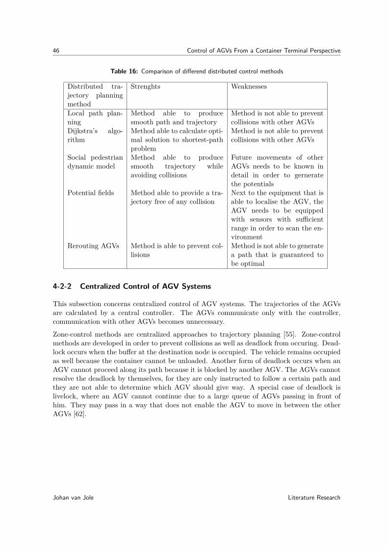
46 Control of AGVs From a Container Terminal Perspective
Table 16: Comparison of differend distributed control methods
Distributed tra-jectory planningmethod
Strenghts Weaknesses
Local path plan-ning
Method able to producesmooth path and trajectory
Method is not able to preventcollisions with other AGVs
Dijkstra’s algo-rithm
Method able to calculate opti-mal solution to shortest-pathproblem
Method is not able to preventcollisions with other AGVs
Social pedestriandynamic model
Method able to producesmooth trajectory whileavoiding collisions
Future movements of otherAGVs needs to be known indetail in order to gerneratethe potentials
Potential fields Method able to provide a tra-jectory free of any collision
Next to the equipment that isable to localise the AGV, theAGV needs to be equippedwith sensors with sufficientrange in order to scan the en-vironment
Rerouting AGVs Method is able to prevent col-lisions
Method is not able to generatea path that is guaranteed tobe optimal
4-2-2 Centralized Control of AGV Systems
This subsection concerns centralized control of AGV systems. The trajectories of the AGVsare calculated by a central controller. The AGVs communicate only with the controller,communication with other AGVs becomes unnecessary.
Zone-control methods are centralized approaches to trajectory planning [55]. Zone-controlmethods are developed in order to prevent collisions as well as deadlock from occuring. Dead-lock occurs when the buffer at the destination node is occupied. The vehicle remains occupiedas well because the container cannot be unloaded. Another form of deadlock occurs when anAGV cannot proceed along its path because it is blocked by another AGV. The AGVs cannotresolve the deadlock by themselves, for they are only instructed to follow a certain path andthey are not able to determine which AGV should give way. A special case of deadlock islivelock, where an AGV cannot continue due to a large queue of AGVs passing in front ofhim. They may pass in a way that does not enable the AGV to move in between the otherAGVs [62].
Johan van Jole Literature Research

4-2 Trajectory Planning and Collision Avoidance 47
Most of the central controlled AGV systems are zone-controlled; the AGVs cannot enter azone unless they have the permission of the traffic control system to do so. The containerterminal is divided into zones. The deadlock prediction looks ahead to the future zones thatthe AGVs will cross and lists the zones that will be crossed by more than one AGV [58]. Thesedeadlock situations will be resolved by the planning algorithm, one AGV will let the otherAGV pass. This can be done in two ways, slowing the conflicting AGV down or delaying thedeparture time of this AGV so it still is able to travel at constant velocity along the path.
Dynamic algorithms are able to incorporate forecasts of the traffic in order to avoid congestionof the terminal. When a zone is occupied, the interval between the arrival of the vehicle at thezone and the vehicle leaving the zone will be listed. This time window is used as a planningparameter for the other AGVs [63].
A dynamic approach to the scheduling and route planning of AGVs outperforms the staticapproach [64]. This is in the case the transit times for the AGVs on each arc are constant,acceleration and cornering effects are not yet modeled. The computation time is low enoughin order for this system to be implemented at automated container terminals. Reference [64]applied a dynamic scheduling approach to trajectory planning of zone-controlled AGVs.
Another centralized control method is based on Petri nets. Petri nets are often used whensolving scheduling or routing problems of various types of equipment. This method of schedul-ing routes is explained in detail in [57]. This method is used in order to balance the loadacross the system. The transportation tasks can be distributed evenly to all the AGVs.
A dynamic routing method is another centralized control method which is developed to avoidcollisions [58]. The paths of the AGVs are calculated, these paths are the shortest routebetween the origin and destination nodes. The AGVs will only drive away from the originnode when the path is not crossed by other AGVs. It waits as long as it takes to have afree path. The AGVs do not travel along paths that are fixed on the terminal; decreasingthe average traveled distance. The system operates in real-time and uses information onthe planned trajectories of the other vehicles in order to determine the routes for incomingtransportation requests.
The final important centralized control method is the time-constrained trajectory planningmethod [59]. This trajectory planning method takes the other AGVs into account as if theyare moving obstacles. The AGV has a time constraint; the actions that will delay the arrivalof the AGV beyond its arrival window are penalized. High velocities are penalized as wellin order to maintain stability of the vehicles and to reduce the energy consumption. Allconstraints available in the model are designed to create an AGV that arrives on time whiledriving at the minimum velocity required for the AGV to arrive on time.
Table 17 lists the weaknesses and strengths of a central controlled AGV system.
Literature Research Johan van Jole
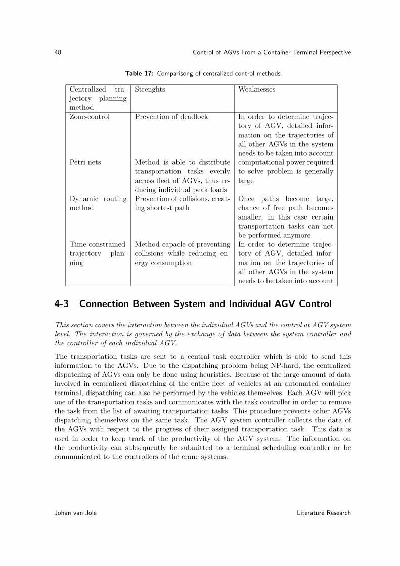
48 Control of AGVs From a Container Terminal Perspective
Table 17: Comparisong of centralized control methods
Centralized tra-jectory planningmethod
Strenghts Weaknesses
Zone-control Prevention of deadlock In order to determine trajec-tory of AGV, detailed infor-mation on the trajectories ofall other AGVs in the systemneeds to be taken into account
Petri nets Method is able to distributetransportation tasks evenlyacross fleet of AGVs, thus re-ducing individual peak loads
computational power requiredto solve problem is generallylarge
Dynamic routingmethod
Prevention of collisions, creat-ing shortest path
Once paths become large,chance of free path becomessmaller, in this case certaintransportation tasks can notbe performed anymore
Time-constrainedtrajectory plan-ning
Method capacle of preventingcollisions while reducing en-ergy consumption
In order to determine trajec-tory of AGV, detailed infor-mation on the trajectories ofall other AGVs in the systemneeds to be taken into account
4-3 Connection Between System and Individual AGV Control
This section covers the interaction between the individual AGVs and the control at AGV systemlevel. The interaction is governed by the exchange of data between the system controller andthe controller of each individual AGV.
The transportation tasks are sent to a central task controller which is able to send thisinformation to the AGVs. Due to the dispatching problem being NP-hard, the centralizeddispatching of AGVs can only be done using heuristics. Because of the large amount of datainvolved in centralized dispatching of the entire fleet of vehicles at an automated containerterminal, dispatching can also be performed by the vehicles themselves. Each AGV will pickone of the transportation tasks and communicates with the task controller in order to removethe task from the list of awaiting transportation tasks. This procedure prevents other AGVsdispatching themselves on the same task. The AGV system controller collects the data ofthe AGVs with respect to the progress of their assigned transportation task. This data isused in order to keep track of the productivity of the AGV system. The information onthe productivity can subsequently be submitted to a terminal scheduling controller or becommunicated to the controllers of the crane systems.
Johan van Jole Literature Research

4-3 Connection Between System and Individual AGV Control 49
In the case of centralized control of AGV systems, the central controller must send the in-formation with respect to the path and trajectory planning to each AGV-controller. Theindividual AGV-controller must make sure that the AGV adheres to the trajectory that iscalculated by the AGV system controller. The disadvantage of centralized control is it havinga single point of failure, this means that when the centralized controller fails all AGVs stopworking. The advantage of a distributed control architecture is that the complexity as well asthe amount of calculations that need to be performed by the AGV task controller are reduced.The routes are calculated by the AGVs themselves. Each AGV is informed by all other AGVson their planned trajectories in order to avoid collisions from occurring.
The information exchange between the AGVs can either occur directly or indirectly. Withdirect communication between AGVs, each AGV will send its information to all other AGVs.Indirect communication occurs when the AGV sends its information to the AGV systemcontroller, where the other AGVs can collect the data they need whenever they need to doso.
A hybrid form is also an option for control of AGV systems. This form is called hierarchicalcontrol. With hierarchical control, the controllers are able to communicate with each other(like in the case of distributed control) but are supervised by other controllers [65]. Thesupervisory controllers are situated at a higher hierarchical level. The supervisory controlleris able to intervene in case two controllers at a lower hierarchical level are in conflict witheach other.
If for whatever reason the AGV is delayed, the AGV is able to calculate the amount of delayand can adjust the velocity planning in order to remain on schedule. This enables the AGVto reduce the error and track the velocity profile accurately. When the trajectory planningis changed or when the delay becomes too large, the AGV must inform the other AGVs, fortheir routes may need to be altered as well. The routes of the other AGVs may be altered inorder to prevent collisions, queueing and deadlock from taking place.
Figure 20 shows the interaction between the AGV control at system and at individual level.The type of information that is exchanged is shown along with the direction of communication
Figure 20: Interaction between AGV control at system and at individual level
Literature Research Johan van Jole

50 Control of AGVs From a Container Terminal Perspective
4-4 Conclusion
The dispatching problem of AGVs is in general NP-hard, which means that centralized controlof AGV systems at automated container terminals can only be performed using heuristics (asis done in zone-controlled AGV systems). Otherwise, calculation of the dispatching orderwould take too much time.
In order to overcome this, distributed approaches are implemented at automated containerterminals in order to control the AGV systems. The method based on the social pedestriandynamic model is one of the distributed control methods suited for trajectory planning ofAGVs. The AGVs communicate with each other on both their routes and trajectories inorder to avoid collisions between them. Each AGV needs to know the trajectories and pathsof all other AGVs. The AGV must then determine if there are any conflicts.
Distributed control is able to provide satisfactory performance because the computation timesare low compared to centralized control. The dispatching procedure can be solved in order todetermine the optimal solution. The global optimum is the dispatching order with the lowestmakespan of the vessels, trains and trucks.
In order to create an AGV system which is able to satisfy the demands of the containerterminal at all times, a minimum number of AGVs is required. The minimum amount ofvehicles that is necessary in order to achieve stable system performance can be calculatedusing for instance the method mentioned in [66]. This calculation includes the stochasticbehavior of the arrival of containers and is able to calculate the minimum required vehiclenumber needed in order to prevent excessive queues from forming somewhere in the system.The reader is referred to [67] in order to obtain an insight into a multitude of methodsand design guidelines for dispatching, vehicle positioning, battery management, routing anddeadlock avoidance for AGVs.
In the current situation, the energy requirements are not taken into account during theplanning of the trajectories. New research can be performed in order to come up with atrajectory planning method that minimizes the energy requirement while preventing collisionsand deadlocks.
Another open problem concerns centralized control of AGV systems. Due to the large amountof data involved, the calculation time of the controller is too large. The problem is to find away to obtain the optimal solution within a sufficienly small timeframe.
The last open problem concerns distributed control, the AGV controller needs to obtaininformation on the location and heading of the surrounding AGVs. The information can beinformation on AGVs within a certain range of the AGV or information on all the AGVs inthe system. Both options create different requirements for the control of AGVs at systemlevel as well as the control of AGVs at individual level.
Johan van Jole Literature Research
Chapter 5
Individual Gantry Crane Control
The previous chapters concerned control of AGVs, this chapter will focus on the control ofgantry cranes at individual level. The first section considers the control of gantry cranesin general. The specific control methods applied to quay cranes, RMGs and ASCs arecovered in the second, third and fourth sections respectively. The penultimate sectiondiscusses the energy efficiency of the gantry cranes that are used at automated containerterminals. The last section concludes this chapter.
Because all container cranes at automated container terminals are gantry cranes, the controlprocedures for these cranes are similar, because the cranes all share the same construction lay-out. The gantry cranes all have the same type of actuators and the control goals are similar.The control goal of the gantry crane is to transport a container from origin location to thedestination location. The difference between the several types of gantry cranes is the distanceand path that must be travelled in order to achieve the control goal. The first section coversthe control methods for gantry cranes which are applicable to each type of container crane.The application of the types of cranes is different, this means that the control proceduresfor each type of container crane are slightly different as well. The control procedures for thedifferent types of container cranes are outlined in their respective sections.
The assignment of tasks to cranes is the topic of the next chapter. The cranes are controlledat individual level in order to complete the handling tasks. The crane is supplied withinformation on the position of the containers to be handled, the crane controller must convertthis information into actions. These actions are performed by actuators on the crane in orderto handle the container.
Literature Research Johan van Jole
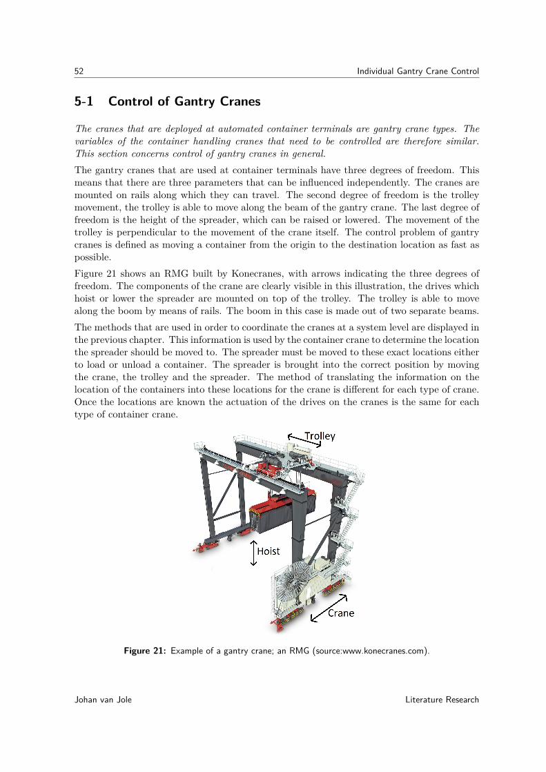
52 Individual Gantry Crane Control
5-1 Control of Gantry Cranes
The cranes that are deployed at automated container terminals are gantry crane types. Thevariables of the container handling cranes that need to be controlled are therefore similar.This section concerns control of gantry cranes in general.The gantry cranes that are used at container terminals have three degrees of freedom. Thismeans that there are three parameters that can be influenced independently. The cranes aremounted on rails along which they can travel. The second degree of freedom is the trolleymovement, the trolley is able to move along the beam of the gantry crane. The last degree offreedom is the height of the spreader, which can be raised or lowered. The movement of thetrolley is perpendicular to the movement of the crane itself. The control problem of gantrycranes is defined as moving a container from the origin to the destination location as fast aspossible.Figure 21 shows an RMG built by Konecranes, with arrows indicating the three degrees offreedom. The components of the crane are clearly visible in this illustration, the drives whichhoist or lower the spreader are mounted on top of the trolley. The trolley is able to movealong the boom by means of rails. The boom in this case is made out of two separate beams.The methods that are used in order to coordinate the cranes at a system level are displayed inthe previous chapter. This information is used by the container crane to determine the locationthe spreader should be moved to. The spreader must be moved to these exact locations eitherto load or unload a container. The spreader is brought into the correct position by movingthe crane, the trolley and the spreader. The method of translating the information on thelocation of the containers into these locations for the crane is different for each type of crane.Once the locations are known the actuation of the drives on the cranes is the same for eachtype of container crane.
Figure 21: Example of a gantry crane; an RMG (source:www.konecranes.com).
Johan van Jole Literature Research

5-1 Control of Gantry Cranes 53
Figure 22 shows an example of the system and control cycle. The system and control cyclerelates the controller to the system that has to be controlled. In this case, the system understudy is the gantry crane. Measurements are performed on the gantry crane in order for thecontroller to determine the actions that should be applied to the system.
Figure 22: The system and control cycle for gantry cranes.
The measurements on gantry cranes are the position and velocity of the crane, the trolleyand the spreader. The measurements of the crane position can be performed using RFIDtechnology. Receivers located on the crane can determine the distance between the crane andthe RFID transmitters. The position of the crane can also be measured using wheel encoders,which measure the angle of rotation of the wheels. In case several cranes are mounted on thesame rail, they are provided with scanning lasers to measure between them.
The position of the trolley is measured in equal ways as the position of the crane is measured.But next to RFID technology and wheel encoders, laser range finders can be used [26]. Thetrolley is equipped with lasers which measure the distance between the trolley and a fixed plateon the boom. The problem of measuring the position of the spreader is not one dimensional,like the position measurement of the crane and trolley. The connection between trolley andspreader lacks the stiffness necessary to restrain the trolley in one direction.
The position of the spreader with respect to the trolley can be measured using laser scanners.The measured distance between the spreader and the trolley needs to be corrected for theorientation of the spreader. The spreader is able to rotate about three axes, the angle ofthe spreader can be measured using inclinometers, this angle is used when determining theexact location of the spreader [68]. The position of the spreader can be tracked by imageprocessing systems as well. The spreader is equipped with markers, which are tracked bycameras mounted on the trolley [69]. The drive of the hoisting mechanism on the trolley canbe equipped with an rpm sensor in order to determine the length of the cable between thetrolley and the spreader. This information is coupled with the information on the position ofthe markers in order to accurately determine the position of the spreader.
Literature Research Johan van Jole

54 Individual Gantry Crane Control
The crane is supplied with three different actuators, the hoisting motors, trolley drive motorsand crane drive motors. The spreader is put in the correct position with the use of thesethree actuators. The actions that are computed by the controller are the torques that needto be supplied by the drives.
Disturbances (like for instance windloads and frictional loads) act on the system. Thesedisturbances cannot measured, the magnitude of these disturbances can be derived from themeasurements on the position of the crane, trolley and spreader. The control actions arerecalculated several times in order to compensate for these disturbances
The goals inside the controller change over time. Each time a container is handled, thecontroller is supplied with a new goal. This goal concerns a new handling task, to transporta container from a known origin position to a known destination position.
Control of a gantry crane is performed by evaluating a cost function. This cost function isa function of the deviation between the current and the desired state, the time available toperform the action, the boundary values (like maximum velocity and acceleration) and theenergy required to reach the desired state. The minimum of this cost function is determinedin order to find the optimal control for the gantry crane.
The controller of a gantry crane is supplied with equations describing the mechanical be-haviour of the spreader. These equations are solved in order to obtain the required controlactions [70]. The crane determines the optimal trajectory of the container and by solving theequations of motion the actions required to achieve this trajectory.
5-2 Control of Quay Cranes
This section concerns the control of quay cranes. This section concerns the positioning of thecrane with respect to the vessel, twistlock handling and concludes with the control of skew andsway. This section is divided into subsections alignment of the crane, twistlock handling andsway angle control.
5-2-1 Alignment of the Quay Crane
The vessels that are handled by the quay cranes do not remain in a fixed place. When thevessels are moored at the berth, they are connected to the quay wall by cables. These cablesallow for movements of the vessel. These movements are caused by the waves and wind loadsthat impact on the vessel.
Difficulties are caused by these relative movements of the vessel with respect to the crane.Because the container is fixed relative to the vessel, the container also moves with respect tothe quay crane. The spreader must be able to follow the movements of the container in orderto load or unload a container. The movements of the containers must be tracked in orderto lift the containers on or off the vessel. The position of the containers on the vessel areknown to the crane. This means that the movements of vessel itself can be tracked in orderto determine the orientation and position of the container.
Johan van Jole Literature Research
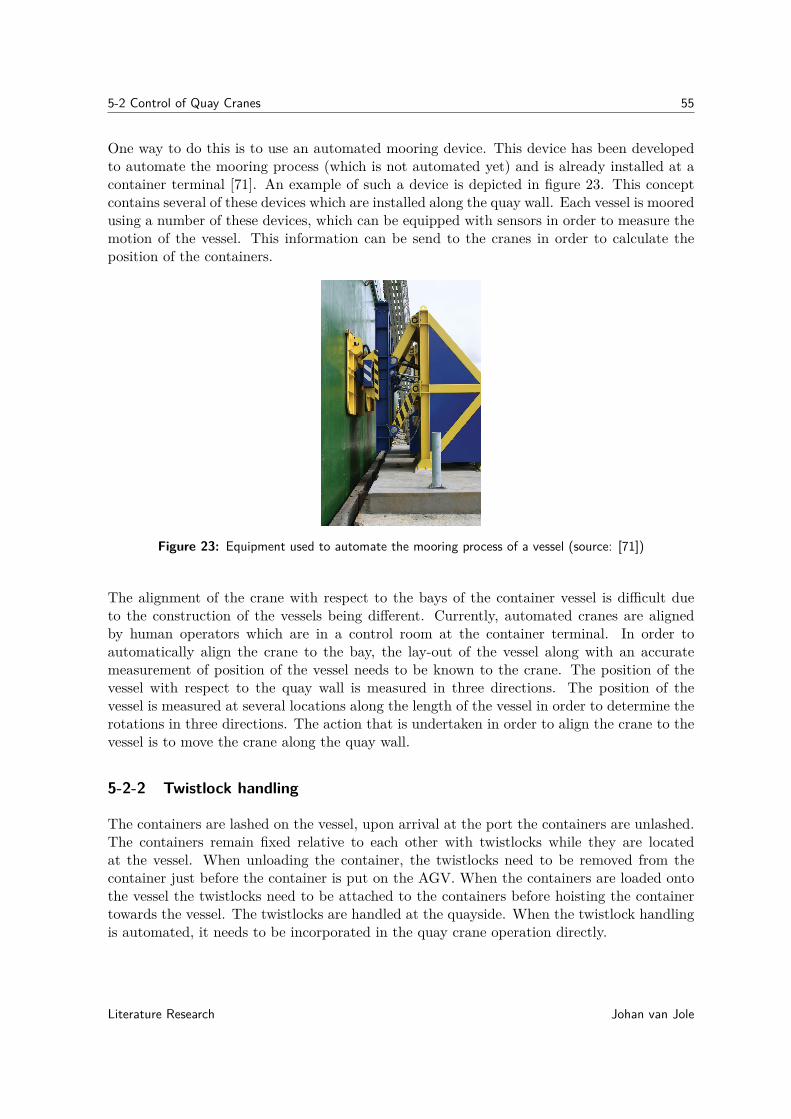
5-2 Control of Quay Cranes 55
One way to do this is to use an automated mooring device. This device has been developedto automate the mooring process (which is not automated yet) and is already installed at acontainer terminal [71]. An example of such a device is depicted in figure 23. This conceptcontains several of these devices which are installed along the quay wall. Each vessel is mooredusing a number of these devices, which can be equipped with sensors in order to measure themotion of the vessel. This information can be send to the cranes in order to calculate theposition of the containers.
Figure 23: Equipment used to automate the mooring process of a vessel (source: [71])
The alignment of the crane with respect to the bays of the container vessel is difficult dueto the construction of the vessels being different. Currently, automated cranes are alignedby human operators which are in a control room at the container terminal. In order toautomatically align the crane to the bay, the lay-out of the vessel along with an accuratemeasurement of position of the vessel needs to be known to the crane. The position of thevessel with respect to the quay wall is measured in three directions. The position of thevessel is measured at several locations along the length of the vessel in order to determine therotations in three directions. The action that is undertaken in order to align the crane to thevessel is to move the crane along the quay wall.
5-2-2 Twistlock handling
The containers are lashed on the vessel, upon arrival at the port the containers are unlashed.The containers remain fixed relative to each other with twistlocks while they are locatedat the vessel. When unloading the container, the twistlocks need to be removed from thecontainer just before the container is put on the AGV. When the containers are loaded ontothe vessel the twistlocks need to be attached to the containers before hoisting the containertowards the vessel. The twistlocks are handled at the quayside. When the twistlock handlingis automated, it needs to be incorporated in the quay crane operation directly.
Literature Research Johan van Jole

56 Individual Gantry Crane Control
The automated handling of twistlocks can be performed using a special platform. This is notapplied a lot because the platform requires a lot of maintenance and the investment costs aresubstantial [72]. These platforms need to be mounted on the structure of the crane, whichneeds to be modified to accomodate the platform. The last reason that the platform is littleused is that the supply of a sufficient number of twistlocks to the platform causes problems.Unlike containers, twistlocks are not standardized and a large variety of different types oftwistlocks are in use. This makes the automation of twistlock handling difficult.
An Universal Container Locking System (UCLS) is developed in order to solve the twistlockhandling problem. This system consists of special locking units that unlock when the spreaderis engaged and lock when the spreader disengages. The need for twistlock handling is removed,reducing the handling costs. As twistlock handling is one of the most dangerous jobs at acontainer terminal, safety at the terminal increases when this system is used [72].
Measurements are performed by the quay crane in order to determine whether or not twist-locks are attached at the bottom of the container. One way to measure the presence oftwistlocks is to use an optical system with image processing software. The actions that areperformed are either attaching or removing the twistlocks.
5-2-3 Sway Angle Control at Quay Cranes
Due to the large length of the cables between the spreader and the trolley (which are around50-60 m [25]) the spreader is able to move in two directions with respect to the trolley, theseare called skew and sway. Figure 24 illustrates sway, this angle is represented with θ3. Withsway, the spreader moves back and forth with respect to the trolley in the direction of theboom. Skew is the movement of the spreader with respect to the trolley in the directionparallel to the quay wall. Because the container needs to be below the spreader in order todrop the container, the productivity of the crane is reduced. Before dropping the containeroff, the sway and skew motions needs to be damped out.
Figure 24: Illustration of sway at container cranes [source: patent US6250486 B1].
Johan van Jole Literature Research

5-3 Control of RMGs 57
Reducing the angle of sway at automated container cranes is performed in order to increasethe handling performance. Handling performance is increased because the crane does nothave to wait until the sway motion is damped out before lowering the container onto theAGV or vessel.
Another important reason for reducing sway is safety near the container crane. When theangle of sway cannot be controlled by the crane the container might be able to swing arounddangerously, hitting everything on its way. This may damage the AGVs or even the vessels,as well as creating a hazard for the people that are at work in the vicinity of the crane (forinstance maintanance operators or people at work on the vessel).
Sway is a swinging motion of the load in the direction of trolley travel. Currently, thecontroller manipulates the inputs of the crane operator in a way that sway of the load iscounteracted. It is reported that experienced crane operators currently are able to achieve ahigher productivity when the anti-sway system is turned off [38]. This shows the difficulty insuccessfully automating a quay crane. As explained in [24], the cause for the lower produc-tivity with the anti-sway system in action is significant non-linearities that are present in thecrane-trolley interactions which are currently not accounted for.
One method that reduces sway uses an inclinometer to measure the inclination angle of thespreader itself [68]. The angle of the spreader with respect to the trolley is already measured(as discussed in the previous section). The evaluated state is composed of the parametersdescribing the states of the trolley and the spreader. Depending on the state of this systemthe controller calculates the required actions that reduce the sway angle. The angle of swayis reduced by changing the trajectory of the trolley. During acceleration and braking, thevelocity of the trolley is controlled in a way that reduces sway. In case a large angle of swayoccurs, the trolley can move against the direction of sway in order to damp this sway motion.The action that is performed is adjusting the velocity of the trolley in order to eliminate sway.
Another method designed to reduce sway makes use of an image processing system which isable to accurately track the spreader. Once the sway angle is determined, the crane controllerdetermines which actions can be taken in order to reduce sway. Sway is reduced by an inertiadamper mounted on top of the spreader. The inertia damper comprises of a mass which isconnected to springs. This mass is moved against the direction of sway, damping this swayingmovement [69].
The actions in the sway-reducing controllers are calculated from the equations of motion. Theequations describe the sway angle as a function of positions, velocities and accelerations.
5-3 Control of RMGs
This section concerns the control of individual RMGs. The way RMGs handle the loadplan ofthe train is discussed as well as is the position control of the crane relative to the train. Thissection consists of the subsections aligning RMGs to trains and controlling sway.
Literature Research Johan van Jole
58 Individual Gantry Crane Control
5-3-1 Aligning RMGs to trains
The goal is to align the RMG to the train in a so the RMG is able to load and unload thecontainers. The position of the train with respect to the crane must be known in order todetermine the location of the containers with respect to the crane.
The loadplan of a train is different compared to that of a vessel. The containers at trains areonly categorized according to destination. Here, the destination of the containers is consideredto be the train handling station at which they are lifted off the train again. The position ofthe containers on the train are detailed in the loadplan [73].
The position of the train and the rail cars which provide space for the containers can bedetermined in several ways. One possible way might be having a marker on each rail carwhich can be tracked by a camera system that is mounted on the RMG.
Another method might be to drive the train up to a fixed reference point (the end of thetrack for instance) and calculate the positions of the cars. The positions can be calculatedusing the dimensions of the locomotive and the used cars.
5-3-2 Sway Angle Control of RMGs
At automated RMGs, the sway angle is controlled using the methods developed for quaycranes. The control objective as well as the methodology remains the same. The rope lengthof the RMG is around 20 m [27], which is less compared to that of the quay crane. Thehoisting and trolley travel velocities of the RMG are lower than the quay crane [25], [27]. Theshorter rope length reduces sway somewhat, along with the lower velocities. The methodsused at container cranes can thus be applied to RMGs as well.
Trains are still operated by humans, this means that the train handling process must beperformed in a safe environment. The angle of sway needs to be restricted in order to preventthe container hitting the train or the personell that works in the vicinity of the trains.
When the RMG is aligned to the train, the crane is moved along the length of the train. Afterthe handling of each container, the crane will move towards the next train car. The craneand the trolley movements must be coordinated in a way that minimizes the sway angle ofthe containers.
The sway controllers need to be supplied with dynamical models describing the sway angleas a function of the velocity and position of both the crane and trolley.
5-4 Control of ASCs
This section discusses the control regarding the ASCs.
The stacking algorithms that are used to assign the ASC to handling tasks are introduced inthe next chapter. The stacking controller determines where the containers need to be stacked.When containers need to be taken out of the stack, the crane controller gets a signal to pickthe container up and deliver it to the AGV or the truck. The positions of the trucks and theAGVs are known to the ASC controller.
Johan van Jole Literature Research

5-5 Energy Efficiency of Container Cranes 59
The actuation of ASCs is covered in the fist section on the control of gantry cranes. At thesecranes sway needs to be controlled because a container with a large sway angle is able tocause damage to the stacked containers, due to the spacing between the rows of containersbeing relatively small.
The velocity of an ASC is higher than that of an RMG or quay crane in order to stackand unstack the containers within a reasonable amount of time [28]. This is the reason thatbesides the control procedures that reduce the angle of sway, as mentioned in the section onquay cranes another method of controlling sway is developed. This method does not makeuse of controllers, it is controlled by a mechanical linkage.
This mechanical linkage contains a beam which is connected to the spreader. This beam addssufficient stifness in order to diminish the sway angle. This concept is illustrated in 25.
Figure 25: An ASC equipped with a beam in order to counteract sway [source: www.terex.com].
5-5 Energy Efficiency of Container Cranes
This section concerns the reduction of the energy consumption of container cranes. Reducingthe energy consumption of container cranes results in lower operational costs. This section isdivided into the subsections scheduling and regenerative braking.
5-5-1 Increasing Energy Efficiency by Alternative Scheduling Procedures
The scheduling of the movements of gantry cranes influences the energy efficiency of the con-tainer handling process. Alternative scheduling procedures can increase the energy efficiencyof the container gantry crane.
During the loading operation of a vessel, the crane moves the container to the vessel. Thecrane subsequently moves the spreader to the quay in order to start a new cycle. With the useof dual cycling, the spreader will transport a container to the quay. Unloading and loadingoperations are combined in order to reduce the amount of empty trolley moves [74].
Literature Research Johan van Jole

60 Individual Gantry Crane Control
Reducing the amount of empty trolley moves reduces the energy consumption of the quaycrane. This procedure was designed in order to increase the container handling efficiency.The energy efficiency is implicitly improved because the amount of trolley moves is reduced.Moving a trolley requires energy, reducing the amount of these movements thus reducesthe total energy consumption. The scheduling procedure becomes more complicated, thehorizontal transportation and the stacking cranes must be able to keep up when the vessel isloaded and unloaded at the same time.
When waste energy is recovered (as mentioned in the next subsection), this can be suppliedto the electricity grid. When the movements of the cranes are synchronized, the efficiencyof the cranes can be further improved [75]. When one crane lowers a container it recoversenergy, this energy can be directly supplied to a crane which hoists a container. The energydoes not need to be temporarily stored in an energy storage, increasing the overall efficiency.This method requires a detailed scheduling procedure which determines which cranes need tolift and which cranes need to lower a container. When the cranes are scheduled in this way,the peak power demand is reduced. The scheduling procedure which is able to synchronizethe movements of the cranes is a lot more complex compared to conventional schedulingprocedures. All cranes (RMGs, ASCs and quay cranes) need to be scheduled simultaneouslyin order to synchronize the movements with respect to the simultaneous consumption andregeneration of energy.
5-5-2 Increasing Energy Efficiency by Regenerative Braking
When the potential energy that is released when a container is lowered is not dissipated acrossa braking resistor but instead is regenerated, the energy efficiency increases. The energy thatis harvested using regenerative braking can be stored locally or supplied to an electricity grid.
When energy is stored local to the crane, the energy is used when the crane hoists anothercontainer. The energy can be stored using a flywheel [32], supercapacitor bank [31] or a largebattery. The recovered energy reduces the energy requirement of the quay crane.
The energy required for one move of a quay crane is around 6 kWh [75]. The amount ofauxiliary power of automated cranes is lower than human operated cranes because there is noneed for an air-conditioning system, flood lights and walkway lights. Energy can be recoveredto reduce the energy requirement. The maximum amount of recovered energy amounts toaround 75-80 percent of the energy required to lift a container [75]. This percentage resultsfrom the efficiencies of the motor-generator system and energy storage.
The recovered energy can also be supplied to the electricity grid which the cranes are con-nected to. The energy can be used by other types of equipment, it can be stored in anenergy storage system that is installed at the terminal or the energy can be used to chargethe batteries of the AGVs.
Johan van Jole Literature Research

5-6 Conclusion 61
5-6 Conclusion
The cranes are supplied with handling tasks by the crane scheduling processes which aredescribed in Chapter 6. The location of the containers that need to be handled are knownto the cranes. The spreader handles these containers by actuation of the crane drives, trolleydrives and the hoisting drives. The position of the containers on the transport modality isknown to the crane. In order to locate the container the position of the transport modalitywith respect to the crane needs to be known to the crane.
The quay cranes must be able to track the movements of the vessel in order to lift a containeron or off the vessel. The position of the vessel needs to be measured in order for the crane toline-up with the container bays automatically. The RMGs need to know the position of thetrain in order to know the positions of the containers that need to be loaded or unloaded.
When moving the container, the sway angle needs to be minimized. This is done to maximizethe container handling capacity as well as ensuring the safety of the lifting operations. Thecontroller obtains data on the state of the trolley and the container and calculates the actionsrequired to complete the handling task while keeping the angle of sway within acceptablelimits. The actions that are considered are changing the velocities and positions of the trolleyand the hoisting mechanism.
Automating container cranes gives an opportunity to reduce the energy consumption. Thecost functions in the controllers are suited for implementation of energy consumption strate-gies. This can either happen in the scheduling process of the cranes or by applying regenerativebraking.
The major open problem for quay cranes and RMGs is determining the position of the con-tainers on the vessels and trains. The quay cranes and RMGs need to line up with thetransport modalities, therefore they need to know their position relative to that transportmodality. The position of the containers relative to the position of the transport modalityneed to be known as well in order to determine the position of the containers relative to thecrane.
The previous problem highlights another open problem, communication between the transportmodalities and the cranes. The transport modality needs to communicate the position of thecontainers that need to be handled to the crane. A standard communication protocol needsto be developed which enables the transport modality to communicate with automated cranesat different automated container terminals.
The position of the AGV relative to the crane needs to be determined as well in order to lifta container on or off the vehicle. This problem is equivalent to the problem of locating thetransport modalities. However, because the AGV operates internal to the container terminalthe AGVs can be modified in order for the cranes to determine their position.
Another open problem concerning automated operation of gantry cranes is the interaction ofthe automated equipment with humans. The transport modalities that are handled by thecranes are operated by humans. This means that they will inevitably operate in the vicinityof the automated equipment and measures have to be taken in order to ensure the safety ofthese people. Very few papers adress this issue regarding the automated operation of cranes,therefore more research should be performed in order to determine the measures needed inorder to accomodate for people working in the automated environment.
Literature Research Johan van Jole

62 Individual Gantry Crane Control
Johan van Jole Literature Research

Chapter 6
Control of Gantry Cranes at ContainerTerminal Level
The previous chapter concerns control of individual gantry cranes. The cranes at containerterminals are also coordinated at a container terminal perspective. The cranes need to bescheduled in order to minimize the turnaround time of the vessels and trains. The cranesused on automated container terminals (quay cranes, RMGs and ASCs) are gantry cranes.The first section covers the scheduling of the gantry cranes for handling operations. Thesecond section describes the process of stacking the containers. The last section containsthe conclusion to this chapter.
Scheduling of quay gantry cranes is often considered alongside the berth allocation problem[76]. The berth allocation problem concerns the assignment of vessels to berths. The vesselsall have a different size and they need to be scheduled along the quay wall in a way thatminimizes the handling time for each vessel.
The berth allocation problem will not be revisited in this report, for it is out of the scopeof this research. The reader is referred to [77] and [78] in order to get an insight into theberth allocation problem. The scheduling of the arrival of the vessels, trains and trucks atthe terminal is not considered in this report.
6-1 Scheduling of Quay Cranes and RMGs
This section considers the assignment of gantry cranes to specific handling tasks. A handlingtask is a request to lift a container on or off the vessels, trains or trucks. The first subsectionbriefly introduces the assignment problem of quay cranes to vessels. The second subsectionconcerns the assignment problem for RMGs to trains.
Literature Research Johan van Jole
64 Control of Gantry Cranes at Container Terminal Level
6-1-1 Scheduling of Waterside Operations
Waterside operations are performed at the quay wall, the vessels are loaded and unloaded bythe quay cranes. The problem of scheduling the quay cranes is to minimize the turnaroundtime of all the vessels while respecting the constraints. The sequence of handling operations forevery quay crane needs to be scheduled according to these constraints. The major constraintarises from the rail on which the cranes are mounted, therefore the cranes cannot pass eachother. Another constraint is the maximum crane travel velocity, which is generally low [25].
The crane scheduling problem is often formulated as a mixed integer linear programmingproblem. The mixed integer linear programming problem is formulated to determine thesequence of handling operations for the quay cranes and the vessels. The problem of schedulingthe quay cranes is to find a (near) optimal solution to the assignment problem which satisfiesthe physical constraints. The objective of the controller is to find the optimal solution, theoptimal solution is the solution with the minimum makespan of the set of vessels.
The quay crane assignment problem is defined as determining the sequence of handling oper-ations (the order in which the vessels are served) as well as assigning the quay cranes to thevessels in order to minimize the total makespan of the set of vessels.
The minimum number of cranes that are assigned to a vessel is often defined by the contractbetween the terminal operator and the shipping line [79]. The assignment of cranes to vesselsis not static, the assignment of cranes can change during the handling process of the vessels.This means that during the handling operation of a vessel, the number of quay cranes thatare servicing it might be changing over time.
When more quay cranes are deployed on a vessel, the turaround time of that vessel is reduced.The relation between the number of assigned quay cranes and the turnaround time is notlinear [79]. With every extra quay crane assigned to a vessel, the reduction in turnaroundtime of that vessel becomes smaller. The quay cranes interfere with each other, loweringthe productivity of each crane. The maximum amount of assigned quay cranes is limited bythis decrease in quay crane productivity [76]. This interference effect needs to be taken intoaccount during the process of allocating cranes to vessels. The assignment of quay cranesto vessels should be performed in a way that maximizes the productivity of the system ofquay cranes. Quay crane assignment is vital for handling performance of the vessels and istherefore taken into consideration during the berth planning process.
It is shown that assigning quay cranes to vessels should be preferred over assigning the cranesto berths [80]. The proposed procedure simultanously solves the berth assignment problemand the crane assignment problem. First, a ship sequence is created. Subsequently, thevessels are assigned to berths. After the berth assignment problem is solved, the cranes areassigned to the vessels in order to minimize the turnaround time. The model is formulatedas a mixed-integer linear programming problem.
Another procedure of assigning cranes to vessels only consists of two steps [77]. The modelassumes that the ship sequence cannot be influenced by the terminal. Therefore the modelfirst determines the berthing position of the vessels before heading onto the crane assignmentproblem. The problem is formulated as a mixed-integer linear programming problem. Thisprogram is solved using a genetic algorithm with a fixed planning horizon.
Johan van Jole Literature Research
6-1 Scheduling of Quay Cranes and RMGs 65
An approach formulated as a mixed-integer linear programming problem is developed whichassigns the cranes to holds [81]. This is because in practice, only one quay crane will beassigned to each hold on the vessel. The procedure looks for the holds that need to be handledand subsequently assigns the cranes to the holds in a way that minimizes the makespan ofthe entire set of vessels.
Another approach uses an integer programming model to assign the quay cranes to vessels[82]. Simultaneously, the berth assignment problem is solved in this approach. This procedureuses fixed time segments where the number of quay cranes for each vessel are determined.The assignment is stationary during one time segment.
The previous procedures divided the quay wall into discrete berths. The vessels can also beassigned to a position along the quay wall, instead of sectioning the quay wall into descreteberths. This position is determined by the size of the vessels, the distances between theberthed vessels and the length of the quay wall [83]. The quay cranes are assigned to thevessels based on the order of arrival, berthing position and the size of the vessels.
A simulation method that includes the horizontal transportation function in the crane assign-ment process is developed in [84]. The advantage of this procedure is that the productivityof the cranes and AGVs togehter can be calculated. The calculated productivity serves tocalculate the optimal assignment of cranes to the vessels. This model is not yet implementedbecause the computation time is fairly large, compared to the control methods that werediscussed previously.
The scheduling procedures use mixed-integer programming in order to provide the schedule ofthe quay cranes. The algorithms used to solve the scheduling procedures are not mentionedin this report. The reader is referred to [85] in order to obtain more information on most ofthe algorithms that are used to solve these mixed integer programs.
Table 18 shows the differences of the quay crane scheduling methods that are mentioned inthis chapter. The methods of the assignment of vessels to berths are listesd in the column’berth assignment’. The column ’vessel handling’ lists the scheduling procedures that areused to determine the order of vessel handling. The methods that are used to assign the quaycranes to the handling tasks are listed in the column ’quay crane assignment’.
Literature Research Johan van Jole

66 Control of Gantry Cranes at Container Terminal Level
Table 18: Differences between the different quay crane scheduling methods
Method Berthassignment
Vessel handling Quay crane as-signment
Type of program-ming method
Simultaneousberth andquay craneassignment
Discrete Order of arrivaland size of vessels
Berthing positionand size of vessel
Mixed-integerprogrammingproblem
Two-stagemethod
Discrete Order of arrival Berthing positionand size of vessel
Mixed-integerprogrammingproblem
Hold assign-ment
Discrete Size of vessels Berthing positionand number ofhandling movesper hold
Mixed-integerprogrammingproblem
Fixed timesegments
Discrete Order of arrival Berthing positionand size of vessel
Integer program-ming problem
Continuousberth method
Continuous Order of arrival Berthing positionand size of vessel
Mixed-integerprogrammingproblem
6-1-2 Scheduling of Railway Operations
The railway operations concern the handling of the trains that visit the terminal. Thissubsection introduces the assignment of RMGs to trains. The problem of scheduling of thetrains and RMGs is equivalent to the scheduling of the vessels and quay cranes, the trainsand RMGs need to be scheduled in a way that minimizes the makespan of the trains.
A mixed integer program is constructed which is able to schedule the handling of the trains[86]. The trains are assigned to one of the available tracks based on the time of its arrival atthe container terminal. After the trains are assigned to a track, the handling operations onthe trains are planned.
Another approach uses an integer programming based heuristic method that is able to schedulethe RMGs in order to handle the trains. This scheduling method is able to construct anoperating schedule for the RMGs which has a global optimum [87].
Heuristics can be used to schedule the trains and RMGs simultaneously [88]. This researchshowed that heuristics are able to be successfully implemented on container terminals. Theheuristics are able to handle the complex operating environment of a container terminal.
Table 19 lists the train and RMG scheduling procedures that are mentioned in this section.The programming methods are listed in this table as well.
Johan van Jole Literature Research

6-2 Stacking of Containers 67
Table 19: List of train and RMG scheduling methods
Scheduling method Programming methodScheduling of trains and RMGs Mixed-integer programming problemAssign RMGs to trains Integer programming problemSimultaneous scheduling of trains and RMGs Heuristics
The amount of models regarding the scheduling of trains and RMGs is low compared to themodels that are created in order to schedule vessels and quay cranes. A limited number ofpublications on this subject are available. While the algorithm using heuristics to schedulethe trains performs well, further research may need to be conducted to search for even bettertrain and RMG scheduling methods.
6-2 Stacking of Containers
This section concerns the storage of the containers at automated container terminals. Storageof containers at automated container terminals is performed by automated stacking cranes.There are two problems; scheduling of ASCs and the reduction of unproductive stacking moves.Scheduling of ASCs does not only concern the stacking moves, also the truck handling movesare considered.
The daily operation of stacking the containers is governed by several decision making pro-cesses. These processes allocate space in the container stacking yard for the containers arriv-ing with the incoming vessels and trains. Also, the decision making processes assign stackingequipment to container stacking tasks. Position control and velocity control of the stackingcranes is performed in real-time. When two or more ASCs are mounted on the same rail,they are not supposed to come into contact with each other. The operational decision makingprocess uses a stacking strategy in order to determine when and where to stack a certaincontainer.
The main objectives of a stacking strategy are [89]:
• efficient use of the available storage space
• avoidance of unproductive moves
• timely transportation of containers between the destination position (this is the outgoingtransport modality) and the stack
The third objective implies that the containers that should be lifted onto a vessel should bestacked close to the berthing location of that vessel. The containers that should be lifted ona train should be stacked close to the scheduled arrival location of that train. The containersthat are destined to leave the container terminal by truck should be stacked close to theplanned arrival location of the truck.
Literature Research Johan van Jole

68 Control of Gantry Cranes at Container Terminal Level
The main inputs for the stacking strategy are the type of container (size, reefer, storage ofdangerous goods), the modality with which the containers leave the container terminal andthe date and time of departure [89]. The stacking strategy determines where to store thecontainers. The stacking strategy does not cover the assignment of ASCs to the individualstacking or unstacking tasks.
It is determined that on-line stacking rules are preferred over off-line stacking rules. "Onlineoptimization can avoid suboptimal yard operations that might be caused by a predefinedstowage plan" [89]. Some online stacking rules and their effects are simulated in [90], theserules are designed to find an optimum stacking strategy even when all of the information onthe containers is not available
6-2-1 Scheduling of ASCs
Scheduling the ASCs makes sure that all handling requests are performed within a reasonableamount of time. Scheduling of the ASCs is required in order to prevent the ASCs fromoverloading. When the ASCs are overloaded, the amount of container handling requests arelarger than the maximum amount of requests that can be handled by the ASCs. In this casethe ASCs are not able to match the handling rate of the quay cranes. This means that theyslow the container handling process down. Reducing the amount of reshuffle moves reducesthe load on the ASCs. Reference [91] examines container stacking policies that distribute theworkload between the available ASCs. Other variables that are considered are: the retrievaland stacking costs (distance that has to be travelled by the ASCs and eventual interferenceeffects between different ASCs), a binary variable that indicates whether or not the containerneeds to be rehandled within the stack and the amount of occupied volume in stack comparedto the maximum stacking volume (indication of space utilization).
The arrivals of vessels and trains are known some time in advance, this is generally not thecase with trucks. The handling moves with respect to the trucks cannot be scheduled due tothis reason. When the arrivals of trucks becomes known one half hour to 24 hours in advance,the performance of the stacking process can be improved [92]. Even when the arrival isknown 4 hours in advance, a large improvement can be obtained. Assigning ASCs to trucksis nowadays scheduled on an ad-hoc basis, due to the arrival times being known only minutesin advance.
The containers can be put at an easy accessible location prior to the arrival of the truck. TheASCs can perform these relocation moves when they do not need to service other trucks orAGVs [92]. The moves are be performed when the stacking cranes become idle, thus thesemoves do not interfere with the other container handling processes on the container terminal.The majority of the shuffling moves can in this case be performed prior to the arrival of thetruck. The unproductive moves are shifted from the peak hours to the off-peak hours.
The efficiency of the stacking process is even better when the information on the containersis available prior to stacking. The stacking decisions improve so the attempt to fix poorstacking decisions by having pre-arrival information on the trucks becomes not necessaryanymore. Only when the information on the container is incomplete, this method improvesthe performance of the stacking process and scheduling of the ASCs [92].
Johan van Jole Literature Research

6-2 Stacking of Containers 69
6-2-2 Reducing the Amount of Rehandling Moves
Rehandling moves (also called reshuffling moves) are unproductive container handling movesthat are performed in order to shuffle a container across the stack. This is performed in orderto expose the container that has to be delivered from the stack. Rehandling moves happenin case the container that has to be picked up has other containers stacked on top of it. Thetotal number of unproductive moves increases when the average stacking height increases.
Reducing the amount of unproductive reshuffling moves has a benificial influence on both theworkload of the ASCs and the energy requirement of the stacking process.
Each vessel has a stowage plan, indicating the location of the containers on the vessel [89].The shipping line first makes a rough plan, based on categories, which will be sent to theterminal. Somewhat before arrival, the detailed stowage plan is created. The containers thatbelong to each category are defined in detail. The stowage plan is important for the stabilityof the vessel. The heavier loaded containers are located at the bottom of the vessel, insteadof on the deck. The stowage plan is able to serve as an input into the stacking process inorder to reduce the amount of reshuffling moves.
The containers that need to be transported by trains are also grouped together. The positionon the train does not influence the performance of the transport process, so the containersare not grouped according to categories (they are only grouped by train).
Unproductive stacking moves may arise just before the arrival of a vessel, containers arerepositioned in the stack in order to create empty areas that can accomodate the containersthat are unloaded from the vessel. The containers that will leave with a certain vessel aresometimes collected in one or more specific areas of the stack, the repositioning of thesecontainers causes unproductive stacking moves as well [93]. These extra amount of moves canbe reduced when the sequence at which the containers need to be loaded onto the vessel isknown to the stacking cranes prior to stacking. This sequence can be determined from theinformation on the loading plan of the vessel.
The container handling efficiency increases with a reduction of reshuffling moves. A reductionof reshuffling moves also reduces the energy consumption of the stacking process. The energyconsumption is reduced because the cranes perform less moves per handled container. Thetotal number of reshuffle moves can be estimated for a given stack lay-out and calls (incomingvessels or trains) [?]. The stacking strategy needs to minimize the amount of reshufflingmoves.
A stacking procedure using heuristics is proposed in [94], which sorts the goal containers atthe side where the containers will eventually leave the stack. This is an attempt to reducethe average travelled distance for the handled containers. When a train or a vessel arrives,the containers that need to be loaded onto the train or vessel are grouped together. Theheuristics sort the containers according to the vessel or train with which they will leave thecontainer terminal in order to reduce the amount of shuffle moves.
Literature Research Johan van Jole
70 Control of Gantry Cranes at Container Terminal Level
A large reduction of shuffle moves is obtained in [89], where the amount of reshuffle moves isreduced by 80 percent with respect to the situation where containers are stacked at random.The improvement comes from stacking the containers according to categories. The categoriesare defined by mode and date of departure. The containers are stacked on top of each otherwhen the top container is set to leave the container terminal prior to the container below. Theamount of reshuffling moves is significantly reduced. The simulation considered catagorizedstacking in different set-ups, including rules that control the workload of the ASCs.
Table 20 shows an overview of the different stacking procedures that are discussed in thissection along with a short description on the procedures
Table 20: Overview of the different stacking procedures
Stacking procedure Description of procedureRandom stacking Put the container on one of the available stacking positionsCategory stacking Sort containers by their position on the outgoing modalityReverse sequence Sort containers by the order in which they are loaded. the
first ones to be loaded need to be stacked last (so they areon top of the piles)
Outgoing location sorting Sort containers at the side at which they will leave the stack
6-3 Conclusion
The cranes are assigned to vessels by solving the berth assignment problem and crane assign-ment problem simultaneously. The vessels are scheduled in order to maximize the utilisationof the quay wall and to keep the waiting time of each vessel within acceptable limits. Thecranes are scheduled simultaneously to the vessels in order to reduce the makespan of the ves-sels and make sure the handling time for every vessel remains within acceptable limits. Thequay cranes are scheduled in a way that minimizes the makespan for the set of serviced ves-sels. Mixed-integer linear programming models are used to calculate the optimal assignmentof cranes to vessels.
The rail mounted gantry cranes that service the trains are coordinated in a similar fashion tothe scheduling of the quay cranes. First, the trains are assigned to tracks. Subsequently, theRMGs are assigned to the trains in a way that minimizes the makespan of the set of trains.Mixed-integer programs are used in this case as well.
The assignment procedures create a schedule for the quay cranes and RMGs. The schedulesare sent to the individual cranes, which calculate the control actions that are necessary inorder to execute the calculated schedule. These control actions are for instance the crane andtrolley movements. These control actions are discussed in Chapter 5.
The process of stacking the containers is controlled by stacking strategies. These strategiesminimize the amount of rehandling moves in order to maximize the efficiency and performanceof the stacking process. The stacking strategy also calculates the required ASC movements ina way that does not overload the system of ASCs. Category stacking has the best performancecompared to the other stacking strategies.
Johan van Jole Literature Research
6-3 Conclusion 71
When a container needs to be stacked, restacked or unstacked, the location of that containeris sent to the relevant ASC along with the required destination position of that container.The actions that the ASC performs in order to perform the required task are discussed inChapter 5.
The major open problem regarding the control of gantry cranes at container terminal level isthe communication between the types of cranes. Currently, there is no methodology availablewhich is able to connect the quay cranes, RMGs and ASCs. All the container handlingprocesses are connected to each other due to the containers temporarily being stored in thecontainer stack. Therefore a method should be considered that coordinates these processes.
Another open problem is the stacking of refrigerated containers (reefers). These containersneed to be connected to a power supply while they are stored in the stack. It is not clearif automating this process can be cost effective or how connecting the reefers to the powersource can be automated.
Unproductive stacking moves still remain at the truck handling process, due to their arrivaltimes being unknown at the time of stacking. This open problem should be adressed in thefuture. Ways to overcome this by changing the process which delivers containers to the trucksshould be investigated in order to make their arrival times more predictable, thus creating anoption to reduce the unproductive stacking moves at this end of the stack.
Literature Research Johan van Jole

72 Control of Gantry Cranes at Container Terminal Level
Johan van Jole Literature Research

Chapter 7
Conclusion and Recommendations forFuture Research
This chapter will provide the conclusions to this research. The first section discusses theanswers to the research questions. The last section provides recommendations for futureresearch on automated container handling.
7-1 Conclusions of the Literature Research
This section covers the answers to the research questions based on the research that is presentedin the previous chapters.
The main research question was: "How can container handling equipment be automated?"
The main question involves by 4 subquestions. The 4 subquestions that support the mainquestion of this research were:
• What are the current trends on containerized transporation and container terminals?
• What is the current state of automation of container handling equipment?
• What parameters are involved in automating container handling equipment?
• What models and control techniques are used in automated container handling equip-ment?
• What are the current limitations in automating container terminals?
Literature Research Johan van Jole

74 Conclusion and Recommendations for Future Research
The current trends on container terminals are the trend towards automated container handlingand the trend towards an increase in energy efficiency with respect to the container handlingprocess. Container handling is automated in order to reduce the terminal operating costsin areas where human labour costs are high. Automation is also performed in order to keepthe turnaround time of the deep-sea vessels (which remain to grow in size gradually) withinreasonable limits. The energy consumption is reduced in order to reduce the operating costsand to conform to the societal trend towards more energy-efficient processes.
Currently the horizontal transportation system and the stacking process are fully automated.The container cranes are currently unable to lift the containers on or off the vessels or trainsdue to difficulties in aligning the container spreader with the container slots. The cranes areable to transport the containers from the vessel towards the quay automatically.
The parameters that are involved in controlling an automated container terminal are listed intable 21. The parameters that are listed in this table only concern the global parameters. Theparameters can be used at automated container terminals in order to schedule the movementsof all the equipment. The detailed parameters like for instance the tire-road friction coefficientat AGVs is not taken into consideration in this table, for doing so would make for a very longlist of parameters. The parameters presented here are the minimal requirements in order toplan the handling operations.
The control architectures that are applied at automated container terminals are centralizedcontrol, distributed control and hierarchical control.
A centralized control architecture must be able to process a large amount of data. This dataconsists of all the variables of all the pieces of equipment. Because the scheduling processesare NP-hard, an exact solution cannot be found. Heuristics can be used in order to makea centralized controller work. When one piece of equipment sends data that is in error, theactions calculated by the centralized controller may be in error as well. A centralized system isalso vulnerable to failures, when the controller fails the handling process comes to a halt. Theadvantage of centralized control is that the movements of the individual pieces of equipmentcan be coordinated without any conflicts arising. Also, when equipment at an automatedcontainer terminal is replaced, the centralized controller needs to be updated.
The advantage of a distributed control architecture is that it provides redundancy. When onecontroller fails, the other pieces of equipment are still able to perform their functions. Theonly disadvantage is that the controllers must be enabled to communicate with each other.In case the controllers are in conflict which each other, the conflicts need to be resolved inorder to continue the container handling operations.
An hierarchical control structure is able to assist in resolving conflicts between several con-trollers. It has the advantages of a distributed control architecture, but this control architec-ture is much more complex. When equipment is replaced, the other controllers do not needto be updated, equipment can thus be replaced while the other pieces of equipment remainin operation.
The models that are used to control the AGVs are kinematic models and dynamic models.Kinematic models are used in order to plan the trajectory of AGVs. Dynamical models aresuited to control the individual AGVs. The models describing the dynamical interactionare able to accomodate for relatively large velocities of the vehicle. Dynamical models arecurrently used at cranes as well, in order to be able to reduce the sway angle of the container.
Johan van Jole Literature Research
7-1 Conclusions of the Literature Research 75
The challenge of modelling the types of equipment is that the models need to provide accuracy.With large displacements (for instance the angle of sway), the dynamic interactions becomenon-linear. Linear models are more suited for implementation in controllers, the challenge isto create a linear model that is able to estimate the influences the nonlinearities.
The main limitation in the process of automating container terminals is the difficulty ofdetermining the exact location of the containers at trains or vessels. The quay cranes andRMGs need to line up with the containers in order to be able to lift them on or off thetransport modalities. Also the cranes need to detect the exact location of the AGV in orderto lift a container on or off the vehicle. Another limitation is the movement of the vesselduring container handling operations, these movements make determining the exact locationof the containers on the vessel a complex task.
Other open problems do exist as well, but these issues do not disturb the process of automat-ing container terminals. The other open problems concern issues that limit the efficiency ofthe automated container handlig process only. Examples of these problems are the imple-mentation of energy recovery methods or the implementation of vehicle dynamics models atAGVs.
The main research question: "How can container handling equipment be automated?" can nowbe answered. The main issue at automated container handling equipment is coordination.Coordination is performed in order to connect the container handling processes. For instance,the AGV must arrive at the quay crane just in time to collect a container. All the movementsof the equipment need to coordinated in order to handle the containers. The planning andscheduling of the pieces of equipment is very important with respect to the performance ofthe entire terminal. Scheduling of the equipment needs to be perfomed automatically in orderto automate the container terminal.
When the tasks of the equipment are planned, it is possible to determine the detailed actionsthat need to be performed by the actuators that are mounted on the equipment. Theseactuators are controlled in order to make the equipment adhere to the output of the schedulingprocess.
The actions that should be considered for satisfactory performance of an automated containerterminal are the sequence of the handling operations on the vessels, trains and trucks and theassignment of equipment to these handling tasks. The RMGs and quay cranes are scheduledto the trains and vessels respectively. When containers are needed, they inform the stackcontroller that a container has to be delivered. The ASCs, RMGs and quay cranes sendrequests to the AGV system.
The individual performance of the AGVs can be increased using efficient routing algorithmsand models describing the dynamics of the vehicle in order to maximize the velocities of thevehicles. The individual performance of the cranes is determined by the amount of informationon the exact location of the vessels, trains and trucks. Models describing the dynamics of thecranes can increase the performance of these container cranes.
The performance of AGVs can be increased by reducing the amount of energy that is nec-essary in order to conduct the transportation tasks. The energy efficiency of AGVs can beimproved using regenerative braking. The energy efficiency of the cranes can be improved byregenerating the energy when a container is lowered.
Literature Research Johan van Jole
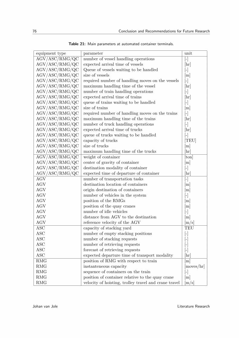
76 Conclusion and Recommendations for Future Research
Table 21: Main parameters at automated container terminals.
equipment type parameter unitAGV/ASC/RMG/QC number of vessel handling operations [-]AGV/ASC/RMG/QC expected arrival time of vessels [hr]AGV/ASC/RMG/QC Queue of vessels waiting to be handled [-]AGV/ASC/RMG/QC size of vessels [m]AGV/ASC/RMG/QC required number of handling moves on the vessels [-]AGV/ASC/RMG/QC maximum handling time of the vessel [hr]AGV/ASC/RMG/QC number of train handling operations [-]AGV/ASC/RMG/QC expected arrival time of trains [hr]AGV/ASC/RMG/QC queue of trains waiting to be handled [-]AGV/ASC/RMG/QC size of trains [m]AGV/ASC/RMG/QC required number of handling moves on the trains [-]AGV/ASC/RMG/QC maximum handling time of the trains [hr]AGV/ASC/RMG/QC number of truck handling operations [-]AGV/ASC/RMG/QC expected arrival time of trucks [hr]AGV/ASC/RMG/QC queue of trucks waiting to be handled [-]AGV/ASC/RMG/QC capacity of trucks [TEU]AGV/ASC/RMG/QC size of trucks [m]AGV/ASC/RMG/QC maximum handling time of the trucks [hr]AGV/ASC/RMG/QC weight of container [ton]AGV/ASC/RMG/QC center of gravity of container [m]AGV/ASC/RMG/QC destination modality of container [-]AGV/ASC/RMG/QC expected time of departure of container [hr]AGV number of transportation tasks [-]AGV destination location of containers [m]AGV origin destination of containers [m]AGV number of vehicles in the system [-]AGV position of the RMGs [m]AGV position of the quay cranes [m]AGV number of idle vehicles [-]AGV distance from AGV to the destination [m]AGV reference velocity of the AGV [m/s]ASC capacity of stacking yard TEUASC number of empty stacking positions [-]ASC number of stacking requests [-]ASC number of retrieving requests [-]ASC forecast of retrieving requests [-]ASC expected departure time of transport modality [hr]RMG position of RMG with respect to train [m]RMG instanteneous capacity [moves/hr]RMG sequence of containers on the train [-]RMG position of container relative to the quay crane [m]RMG velocity of hoisting, trolley travel and crane travel [m/s]
Johan van Jole Literature Research

7-2 Recommendations for Future Research 77
quay crane loadplan of the vessels [-]quay crane instanteneous capacity [moves/hr]quay crane position of quay crane with respect to vessel [m]quay crane position of container relative to the quay crane [m]quay crane velocity of hoisting, trolley travel and crane travel [m/s]
7-2 Recommendations for Future Research
This section concerns recommendations for future research in the field of control of automatedcontainer terminals. The recommendations concern research into control of individual piecesof equipment as well as control of the entire container terminal. This section is divided intosections covering recommendations at terminal level and at equipment level.
7-2-1 Recommendations for Research at Terminal Level
Coordination of the movements of container handling equipment at an automated containerterminal is very important. Coordination is important because the different types of equip-ment depend on each other in order to function properly. The cranes cannot load the transportmodalities without AGVs, to give an example. So far, the scheduling procedures are only ap-plied to one type of equipment at a time. An improvement in the efficiency of the schedulingprocess might by the integration of all scheduling procedures. The various types of equip-ment might be better coordinated. The productivity of the quay cranes might be improvedwhen the AGVs and ASCs are scheduled simultaneously with the quay cranes. These typesof equipment can be scheduled simultaneously in order to obtain a constant flow of containersto and from the quay cranes. The quay cranes do not have to wait for the AGVs or forspecific containers to load on the vessel. The implementation of this scheduling proceduresin the controllers of the various types of equipment needs to be investigated. This researchwill focus on the control architecture and the relation between the different controllers at thecontainer terminal.
Another recommendation concerns the velocity of the individual AGVs. The capacity of theAGV system that is needed to transport the containers changes over time. The necessarycapacity of the system is a function of the number of handled trains and vessels and the timethat is available to handle both the vessels and the trains. Although this subject concerns thevelocity of individual AGVs, it is considered to be a decision at system level. The reason isthat the velocity of AGVs is determined from the capacity requirement of the AGV system.The handling capacity of the system of AGVs is a function of the number of AGVs and theirvelocities. When few AGVs are deployed, they need to drive fast in order to handle theamount of containers. When more AGVs are deployed, the velocity of the AGVs necessary tohandle the containers is reduced.
Literature Research Johan van Jole
78 Conclusion and Recommendations for Future Research
The total resistance in the situation with few fast-moving AGVs is large due to the largeamount of drag that is experienced by the individual vehicles. The total resistance in thesituation with a lot of slow-moving AGVs is large due to the relatively large amount of rollingresistance experienced by the individual AGVs. Somewhere in between these extreme cases,there is an optimal number of vehicles which reduces the total drag. Future research can beperformed in order to evaluate this curve and the relation between this curve and the amountof handling operations on the terminal.
The handling of the twistlocks causes problems. The design of twistlocks is not standardized,so there are a lot of different twistlocks in use. Research can be conducted in order todetermine an appropriate way to deal with these different types of twistlocks automatically.Another research can be performed in order to determine a plan to standardize the twistlockswhich is considered feasible as well as attractive to the actors involved. When twistlockhandling is automated, this feature can be integrated in the design of intelligent containercrane controllers which enable the container cranes to operate without any human supervisionbeing necessary.
When the distance between the berths or tracks becomes large, it might be beneficial to usea trailer system when the vessels or trains are unloaded [35]. These trailers should be pulledby AGVs and need to connect and disconnect automatically. The advantages of having sucha system should be investigated along with their effects on the storage process.
Further research can be performed in order to increase the proportion of direct transshipmentat automated container terminals. With direct transshipment, the containers are exchangedbetween a barge and deep-sea vessel without the container being lifted towards the quay. Thisreduces the number of requests for AGVs and ASCs, as well as increasing the energy efficiency.The effects of this concept on the load planning of vessels and scheduling of quay cranes needto be investigated. The control of the quay crane movements becomes more difficult, becauseboth vessels move with respect to the crane and each other. The quay crane also needs toconsider two load plans at the same time, adding to the complexity of this operation. Theseproblems need to be overcome in order to enable direct transshipment at automated containerterminals.
7-2-2 Recommendations for Research at Equipment Level
The energy efficiency of the individual AGVs is an area in which further research can beundertaken. Research can be performed in order to determine whether hybrid AGVs orelectric powered AGVs should be used at container terminals. The control of these energystorage systems must be taken into account during this research. The AGV must be able todrive with the maximum efficiency in the operational conditions of a container terminal.
When handling the container vessels, the quay cranes need to take the movements of thevessel into account. Research can be performed in order to determine the movements of thespreader given the movements of the vessel. Another research topic might be finding a methodable to damp or restrict the movements of the vessel in a way that these become insignificantto the control of the quay cranes. The movements of the vessel need to be considered in thecontrol problem of the quay crane controllers.
Johan van Jole Literature Research

7-2 Recommendations for Future Research 79
When energy is regenerated at gantry cranes, the amount of regenerated energy can be verylarge. This holds especially for quay cranes because they are the largest cranes at a containerterminal and the containers have a larger amount of potential energy when lifted. The storageof the harvested energy must be considered. It must be investigated whether or not the energymust be stored locally to the crane or supplied to the electrical grid which the cranes aregenerally already connected to.
When energy is supplied to an electrical grid, control procedures have to be designed whichcontrol the flow of energy through the network. When energy is supplied to the network, thiscan be taken into account in the crane scheduling process. For instance, one crane should liftcontainers when another one is lowering a container (the energy does not have to be stored,increasing the energy efficiency of the overall container handling process). Research can beperformed in order to determine the best strategy to accomodate for these procedures.
ALVs (Automated Lifting Vehicles) are already developed, these are used to decouple theASCs and the horizontal transportation function. Decoupling the processes at the quay cranescannot be performed because the cranes move, so they are unable to place the container ontoa rack. This can be overcome by fixing a rack to the structure of the crane. Another methodis to find a suitable lifting concept which is able to lift the container from the ground.
Literature Research Johan van Jole

80 Conclusion and Recommendations for Future Research
Johan van Jole Literature Research
Appendix A
Measurement Center of Gravity ofContainers by AGVs
As mentioned in Chapter 3, the AGVs can be controlled using a model representing thedynamical behavior of the vehicle. An important variable in these models is the center ofgravity of the container that is transported. Because each container is loaded differently,the center of gravity is different for each container. In current literature, no papersdescribe methods that are able to measure this. A method that is able to measure thecenter of gravity of the container is proposed in this appendix.
First, the equations of motion of AGVs are discussed, these are needed in order to measurethe center of gravity of the container that is transported. These equations can subsequentlybe used to control the vehicle once the center of gravity of the container is known.
A-1 Equations of motion of AGVs
The dynamics of the AGV can be described by a set of differential equations describing thestate of the system. These equations are called the equations of motion. The differentialequations describe the steady-state tyre loads as a function of the vehicle parameters andaccelerations of the vehicle.
During acceleration and turning, the vehicle will be subjected to load transfer. The load onthe tyres differs when compared to the static situation. The spring and damper ratios haveno influence on the amount of load transfer, they only influence the transient response. Thisprocess can be modeled linearly when steady state is reached, therefore linear models forlongitudinal and lateral acceleration for the AGV are created.
The free-body diagram for longitudinal acceleration of the AGV is given in Figure 26. Thecenter of gravity of the vehicle is assumed to be known, the position of the center of gravity
Literature Research Johan van Jole

82 Measurement Center of Gravity of Containers by AGVs
of the container is assumed to be spaced randomly. The center of gravity of the container isassumed not to move during the container handling process.
The maximum traction force that can be obtained from the tyres is related to the normalforce on the tyres. This relation is described by the coefficient of friction. The reference planein the model is defined by the ground plane, this is shown by the black line in Figure 26. Theforces that act on the tyres all act on the contact patch. Table 22 lists the abbreviations usedin the model of Figure 26.
Figure 26: Model for longitudinal acceleration of a AGV
Table 22: Summary of the parameters used in the model for longitudinal acceleration of theAGV.
Johan van Jole Literature Research

A-1 Equations of motion of AGVs 83
Symbol MeaningFic The inertia load acting on the container during accelerationFgc Gravity load that acts on the containerFiagv The inertia load acting on the AGV during accelerationFgagv Gravity load that acts on the AGVF Location of the front axleR Location of the rear axleH Distance of center of gravity of the container with respect to the reference planeh Distance of the center of gravity of the AGV with respect to the reference planeFnr Normal load acting on the rear tyresFtr Traction load acting on the rear tyresFnf Normal load acting on the front tyresFtf Traction load acting on the front tyresA1 Horizontal distance of the center of gravity of the container to the rear axleA2 Horizontal distance of the center of gravity of the container to the front axleB1 Horizontal distance of the center of gravity of the vehicle to the rear axleB2 Horizontal distance of the center of gravity of the vehicle to the front axleWb Wheelbase of the vehicle acclongitudinal Longitudinal acceleration
The static solution of the longitudinal distribution of the tyre forces is:
Fnrstatic = Fgc ∗ A2Wb
+ Fgagv ∗ B2Wb
(A-1)
Fnfstatic = Fgc ∗ A1Wb
+ Fgagv ∗ B1Wb
(A-2)
A check of the previous equations gives that the forces on the front and rear axles (Fnf andFnr) combined are equal and opposite to the total gravity forces of the container and theAGV (fgc and Fgagv). Under acceleration (the direction of which is being indicated by thearrow in figure 26), load transfer is described by:
∆Flong = Fic ∗ H
Wb+ Fiagv ∗ h
Wb(A-3)
Fic = mcontainer ∗ acclongitudinal (A-4)
Fiagv = magv ∗ acclongitudinal (A-5)
Fnrdynamic = Fnrstatic + ∆F (A-6)
Fnfstatic = Fnfstatic − ∆F (A-7)
Literature Research Johan van Jole

84 Measurement Center of Gravity of Containers by AGVs
When the AGV decelerates, the acceleration becomes negative and the load transfer reverses.When the acceleration is constant, the inertia loads are constant as well. Acceleration isachieved when the AGV develops a traction force. The traction force is the resultant of thetraction developed minus the rolling resistance of the tyre. The traction force of the tyresequals the inertia load of the container and AGV, for it creates the acceleration of the entiremass. The inertia load is exerted by the vehicle in order to accelerate. It acts opposite to thedirection of travel in this derivation because it is defined as the load that acts on the vehicle.
The free body diagram for the lateral acceleration of the AGV is given in Figure 27. In thiscase, the AGV is turning to the left. This model is similar to the model used to describe thelongitudinal acceleration of the AGV. Table 23 explains the symbols used in the schematicmodel. The symbols for the inertia and gravity loads are the same as in the model forlongitudinal acceleration. The magnitudes of these loads may differ due to differences in themagnitudes of the longitudinal and lateral accelerations.
Figure 27: Model for lateral acceleration of a AGV
Table 23: Summary of the parameters used in the model for lateral acceleration of the AGV
Johan van Jole Literature Research

A-1 Equations of motion of AGVs 85
Symbol MeaningFic The inertia load acting on the container during accelerationFgc Gravity load that acts on the containerFiagv The inertia load acting on the AGV during accelerationFgagv Gravity load that acts on the AGVL Location of the left wheelsR Location of the right wheelsH Distance of center of gravity of the container with respect to the reference planeh Distance of the center of gravity of the AGV with respect to the reference planeFnr Normal load acting on the rear tyresFLR Lateral load acting on the right tyresFnr Normal load acting on the left tyresFLL Lateral load acting on the left tyresC1 Horizontal distance of the center of gravity of the container to the right tyresC2 Horizontal distance of the center of gravity of the container to the left tyresD1 Horizontal distance of the center of gravity of the vehicle to the right tyresD2 Horizontal distance of the center of gravity of the vehicle to the left tyresTw Track width of the vehicleAcclateral Lateral acceleration
The static solution of the lateral distribution of the tyre forces is:
Fnrstatic = Fgc ∗ A2Wb
+ Fgagv ∗ B2Wb
(A-8)
Fnfstatic = Fgc ∗ A1Wb
+ Fgagv ∗ B1Wb
(A-9)
A check of the previous equations gives that the forces on the right and left sides of the AGV(Fnr and Fnl) combined are equal and opposite to the total gravity forces of the containerand the AGV (fgc and Fgagv). Under acceleration (The direction of which is being indicatedby the arrow in figure 27), load transfer is described by:
∆Flat = Fic ∗ H
Tw+ Fiagv ∗ h
Tw(A-10)
Fic = mcontainer ∗ acclateral (A-11)
Fiagv = magv ∗ acclateral (A-12)
Fnrdynamic = Fnrstatic + ∆F (A-13)
Fnldynamic = Fnlstatic − ∆F (A-14)
Literature Research Johan van Jole
86 Measurement Center of Gravity of Containers by AGVs
A-2 Measuring the Center of Gravity of Containers
The equations decribing load transfer during lateral and longitudinal acceleration can besolved simultaneously in order to calculate the load transfer when a vehicle is subjected toboth accelerations at the same time.
The mass of the container can be determined using the spring deformation. The springdeformation is the change in lenght between the state of the container being loaded on theAGV and the state of the AGV being unloaded. Using the spring deformations, the loadof the container can be determined. The longitudinal position of the center of gravity canbe determined using the difference in wheel loading between the front and rear axle. Theload of the front axle and the rear axle is known, therefore the longitudinal position can bedetermined. The lateral position can be determined using the same approach.
When the AGV is loaded, it will drive away in order to deliver the container. When the driveforce during the first acceleration procedure is fixed, the height of the center of gravity can becalculated. The accelerations in longitudinal and lateral direction need to be known. Theseaccelerations can be measured using accelerometers at the front and rear axle of the vehicle.
A-3 Control of AGVs
The previous discussion concerned normal loads at the four wheels of the vehicle. The relationbetween the traction force of the tyres and the normal force on the tyres is called the frictioncoefficient. The friction coefficient between the tyre material and the surface of the terminalneeds to be determined once (during the installation of the AGV system for instance).
Because of this relation, it is useful to be able to know the normal load on the tyres, so theappropriate amount of traction can be provided that enables the AGV to accelerate whileminimizing wheel spin or lock-up. The parameters of the model are fixed, with the exceptionof the center of gravity of the container, the mass of the container and the accelerations. Thetorques of the electric motors can be regulated with the use of this model.
The torques can be calculated using a model of the tyre, representing the relation betweennormal force and traction force under certain circumstances. These tyre-models are non-linear. The most applied tyre model is the Pacejka "magic formula" tyre model [95].
In order to finalize this model, the rolling resistance needs to be measured at the terminal.This parameter is needed in order to calculate the resulting traction forces (in both directions).Aerodynamic loads are not yet accounted for, because both the magnitude of the loads andthe center of pressure are unknown. In order to optimize the model, this can be includedgiven that sensors can be placed to measure the relevant parameters.
Johan van Jole Literature Research

Bibliography
[1] M. Bohlman, “Iso’s container standards are nothing but good news,” ISO bulletin,vol. September, pp. 12–15, 2001.
[2] W. S. Council, “Trade statistics,” 2014. URL: http://www.worldshipping.org/about-the-industry/global-trade/trade-statistics (accessed February 17, 2014).
[3] T. Nedyalkov and T. Andreeva, “Trends in the container shipping and need of a newgeneration container terminals and container vessels,” Technical University of Varna,Bulgaria, 2010.
[4] P. of Rotterdam, “Space for the future,” 2014. URL:https://www.maasvlakte2.com/nl/index/ (accessed March 10, 2014).
[5] R. Haskoning-DHV, “Erhama bin jaber al jalahma shipyard qatar,” 2014. URL:http://www.royalhaskoningdhv.com/nl-nl/projecten/erhama-bin-jaber-al-jalahma-shipyard-qatar/99 (accessed March 10, 2014).
[6] P. Capros, A. de Vita, N. Tasios, D. Papadopoulos, P. Siskos, E. Apostolaki, M. Zam-para, L. Parpissps, K. Fragiadakis, N. Kouvaritakis, and H. Witzke, “Transport and chgemissions; trends to 2050,” European Commission, EU energy, 2013.
[7] P. V. Hall, “Seaports, urban sustainability, and paradigm shift,” Journal of Urban Tech-nology, vol. 14, no. 2, pp. 87–101, 2007.
[8] H. Cederqvist, K. Rintanen, and A. Rechtenwald, “Container terminal yard automation,”Port Equipment Manufacturers Association, 2012.
[9] A. US, “Port of los angeles automated container terminal survey,” Aecom US, pp. 2–5,2012.
[10] T. Saastamoinen, “Latest on port automation,” Konecranes, 2012.
[11] P. of Brisbane, “A modern port,” 2012. URL: http://www.portbris.com.au/news-media/port-of-brisbane-a-snapshot/a-modern-port. (accessed March 11, 2014).
Literature Research Johan van Jole

88 Bibliography
[12] I. Vis and R. de Koster, “Transshipment of containers at a container terminal: Anoverview,” European Journal of Operational Research, vol. 147, pp. 1–16, 2003.
[13] D. Steenken, S. Voß, and R. Stahlbock, “Container terminal operation and operationsresearch: A classification and literature review,” OR Spectrum, vol. 26, pp. 3–49, 2004.
[14] A. Cranes, “Automation and electrification for stacking cranes,” ABB cranes, 2012.
[15] H. P. Holdings, “Facilities at hong kong international terminals,” 2014. URL:http://www.hph.com.hk/globalbusiness/business.aspx?gid=60 (accessed June 11, 2014).
[16] A. D. Terminals, “Equipment at khalifa port container terminal,” 2014. URL:http://www.adterminals.ae/Ports/khalifa-port-container-terminal/equipment (accessedJune 11, 2014).
[17] H. P. Holdings, “Facilities at sydney international container terminal,” 2014. URL:http://www.hutchisonports.com.au/sydney-international-container-terminals (accessedJune 11, 2014).
[18] G. Terminals, “Introducing the new global terminal,” 2014. URL:http://globalterminalexpansion.com/ (accessed June 11, 2014).
[19] P. of Salalah, “Container terminal operational guidelines,” Port of Salalah, 2007.
[20] Belastingdienst-Douane, “Aangiftesysteem ags (dutch version),” 2014. URL:http://www.belastingdienst.nl/wps/wcm/connect/bldcontentnl/belastingdienst/douane_voor_bedrijven/naslagwerken_en_overige_informatie/aangiftesysteem_ags/(accessed Februari 18, 2014).
[21] Solvo, “Technological and commercial aspects of container terminal management usingsolvo,” Port Technology International, vol. 53, 2012.
[22] T. Saanen, “An approach for designing robotized marine container terminals,” PhD.Thesis, Delft University of Technology, pp. 42–48, 2004.
[23] P. McCarthy and M. Jordan, “Dual hoist, tandem 40 crane considerations,” Port Tech-nology International, vol. 34, pp. 111–113, 2004.
[24] N. Zrnic, Z. Petkovic, and S. Bosnjak, “Automation of ship-to-shore container cranes: Areview of state-of-the-art,” FME transactions, pp. 42–48, 2005.
[25] L. C. C. Ltd, “Technical description ship to shore gantry cranes (sts),” Liebherr ContainerCranes Ltd, 2013.
[26] P. Blaiklock, “Automated container handling in port terminals,” TMEIC.
[27] Konecranes, “Rail mounted gantry cranes: wider intermodal horizons,” Konecranes,2010.
[28] T. P. Solutions, “Automated stacking cranes,” 2014. URL: http://www.terex.com/port-solutions/en/products/new-equipment/stacking-cranes/automated-stacking-cranes/index.htm (accessed March 28, 2014).
Johan van Jole Literature Research
89
[29] T. P. Solutions, “Terex gottwald lift agv for decoupling container transport and containerstorage processes,” 2014. URL: http://www.terex.com/port-solutions/en/products/new-equipment/automated-guided-vehicles/lift-agv/index.htm (accessed March 31, 2014).
[30] H. Cederqvist and C. Holmgren, “Investment vs. operating costs: a comparison of au-tomated stacking cranes and rtgs,” Port Technology International, vol. 47, pp. 64–66,2010.
[31] S. Kim and S. Kul, “Control of rubber tired gantry crane with energy storage based onsupercapacitor bank,” IEEE Transactions on Power Electronics, vol. 21, no. 5, pp. 1420–1427, 2006.
[32] H. Hellendoorn, S. Mulder, and B. D. Schutter, “Hybrid control of container cranes,”Proceedings of the 18th IFAC World Congress, Milan, Italy, Aug-Sept 2011, pp. 9697–9702, 2011.
[33] H. Durrant-Whyte, D. Pagac, B. Rogers, M. Stevens, and G. Nelmes, “An autonomousstraddle carrier for movement of shipping containers,” IEEE Robotics and AutomationMagazine, pp. 14–23, Sept 2007.
[34] I. Vis, “A comparative analysis of storage and retrieval equipment at a container termi-nal,” International Journal of Production Economics, vol. 106, pp. 680–693, 2006.
[35] A. Goussiatiner, “Efficiency of multi-trailer systems for ship to stacks container trans-portation,” Port Technology International, vol. 43, pp. 78–82, 2009.
[36] J. Lee, “A passive multiple trailer system with off-axle hitching,” International Journalof Control, Automation and Systems, vol. 2, no. 3, pp. 289–297, 2004.
[37] H. Hees and T. Visser, “Study on the design and similation of a high capacity trans-shipment terminal,” Master of Science thesis, Delft University of Technology, pp. 30–31,2000.
[38] R. Stahlbock and S. Voß, “Operations research at container terminals: a literature up-date,” OR Spectrum, vol. 30, pp. 1–52, 2008.
[39] J. Wang, J. Steiber, and B. Surampudi, “Autonomous ground vehicle control systemfor high-speed and safe operation,” International Journal Vehicle Autonomous Systems,vol. 7, pp. 18–35, 2009.
[40] P. Simionescu and D. Beale, “Optimum synthesis of the four-bar function generator inits symmetric embodiment: the ackermann steering linkage,” Mechanism and MachineTheory, vol. 37, pp. 1487–1504, 2002.
[41] V. Peshekhonov, “Gyroscopic navigation systems: Current status and prospects,” Gy-roscopy and navigation, vol. 2, no. 3, pp. 111–118, 2011.
[42] B. Waldmann, R. Weigel, and P. Gulden, “Method for high precision local positionongradar using an ultra wideband technique,” IEEE Microwave Symposium Digest, MTT-SInternational, 15-20 june 2008, pp. 117–120, 2008.
Literature Research Johan van Jole

90 Bibliography
[43] R. Carelli, C. Soria, O. Nasisi, and E. Freire, “Stable agv corridor navigation with fusedvision-based signals,” IEEE, 28th Annual Conference of the Industrial Electronics Soci-ety, 5-8 nov 2002, vol. 3, pp. 2433–2438, 2002.
[44] O. U. G. information about the Global Positioning System (GPS) and related topics,“Gps accuracy,” 2014. URL: http://www.gps.gov/systems/gps/performance/accuracy/(accessed March 1, 2014).
[45] E. G. N. S. S. Agency, “Galileo is the european global sattelite-based navigation system,”2014. URL: http://www.gsa.europa.eu/galileo-0 (accessed March 1, 2014).
[46] K. Kogoda, W. Wijesoma, and E. Teoh, “Fuzzy speed and steering control of an agv,”IEEE Transactions on Control Systems Technology, vol. 10, no. 1, pp. 112–120, 2002.
[47] I. Vis, “Survey of research in the design and control of automated guided vehicle systems,”European Journal of Operation Research, vol. 170, pp. 677–709, 2006.
[48] S. Pay and Y. Baghzouz, “Effectiveness of battery-supercapacitor combination in electricvehicles,” IEEE Bologna PowerTech Conference June 23-26 2003, Bologna, Italy, 2003.
[49] J. van Mierlo, P. van den Bossche, and G. Maggetto, “Models of energy sources for evand hev: Fuel cells, batteries, ultracapacitors, flywheels and engine-generators,” Journalof Power Sources, vol. 128, pp. 76–89, 2004.
[50] J. Xin, R. Negenborn, and G. Lodewijks, “Energy-aware control for automated con-tainer terminals using integrated flow shop scheduling and optimal control,” Acceptedfor publication in Transportation Research Part C, 2014.
[51] L. Chen, N. Bostel, P. Dejax, J. Chai, and L. Xi, “A tabu search algorithm for theintegrated scheduling problem of container handling systems in a maritime terminal,”European Journal of Operational Research, vol. 181, pp. 40–58, 2007.
[52] L. Qiu, W. Hsu, S. Huang, and H. Wang, “Scheduling and routing algorithms for agvs: Asurvey,” International Journal of Production Research, vol. 40, no. 3, pp. 745–760, 2002.
[53] A. Takahashi, T. Hongo, G. Sugimoto, and N. Ninomiya, “Local path planning andmotion control for agv in positioning,” IEEE/RSJ International Workshop on IntelligentRobots and Systems, Tsukuba, Japan 1989, pp. 392–397, 1989.
[54] A. Shaikh and A. Dhale, “Agv path planning and obstacle avoidance using dijkstra’salgorithm,” International Journal of Application or Innovation in Engineering and Man-agement, vol. 2, no. 6, pp. 77–83, 2013.
[55] M. Fanti, “Event based controller to avoid deadlock and collisions in zone-control agvs,”International Journal of Production Research, vol. 40, no. 6, pp. 1453–1478, 2010.
[56] M. Bahr, R. Donner, and T. Seidel, “A pedestrian dynamics based approach to au-tonomous movement control of automatic guided vehicles,” Robust Manufacturing Con-trol, Lecture Notes in Production Engineering (ed. K. Windt ), pp. 175–187, 2013.
[57] T. Murata, “Petri nets: Properties, analysis and applications,” Proceedings of the IEEE,vol. 77, no. 4, pp. 541–580, 1989.
Johan van Jole Literature Research

91
[58] M. Duinkerken, J. Ottjes, and G. Lodewijks, “Comparison of routing strategies foragv systems using simulation,” Proceedings of the 2006 Winter Simulation Conference,pp. 1523–1530, 2006.
[59] M. Duinkerken, M. van der Zee, and G. Lodewijks, “Dynamic free ranging routing forautomated guided vehicles,” Proceedings of the 2006 IEEE International Conference onNetworking, Sensing and Control, pp. 312–317, 2006.
[60] E. Lopes, E. Aude, J. Silveira, H. Serdeira, and M. Martins, “Application of a blindperson strategy for obstacle avoidance with the use of potential fields,” Proceedings ofthe IEEE International Conference on Robotics and Automation, Seoul, Korea, 2001,pp. 2911–2916, 2001.
[61] N. Wu and M. Zhou, “Agv routing for conflict resolution in agv systems,” Proceedings ofthe 2003 IEEE International Conference on Robotics and Automation Taipei, Taiwan,September 14-19, 2003, pp. 1428–1433, 2003.
[62] R. Mohring, E. Kohler, E. Gawrilow, and B. Stenzel, “Conflict-free real-time agv rout-ing,” Operations Research Proceedings 2004, pp. 18–24, 2004.
[63] S. Rajotia, K. Shanker, and J. Batra, “A semi-dynamic time window constrained routingstrategy in an automated agv system,” International Journal of Production Research,vol. 36, no. 1, pp. 35–50, 2010.
[64] E. Gawrilow, E. Kohler, R. Mohring, and B. Stenzel, “Dynamic routing of automatedguided vehicles in real time,” Mathematics - key technology for the future, pp. 165–177,2008. Published by Springer Berlin Heidelberg.
[65] P. Farahvash and T. Boucher, “A multi-agent architecture for control of agv systems,”Robotics and Computer-Integrated Manufacturing, vol. 20, pp. 473–483, 2004.
[66] M. Ji and J. Xia, “Analysis of vehicle requirements in a general automated guided vehiclesystem based transportation system,” Computers and Industrial Engineering, vol. 59,pp. 544–551, 2010.
[67] T. Le-Anh and M. de Koster, “A review of design and control of automated guidedvehicle systems,” European Journal of Operation Research, vol. 171, pp. 1–23, 2006.
[68] Y. Kim, K. Hong, and S. Sul, “Anti-sway control of container cranes: Inclinometer,observer and state feedback,” International Journal of Control, Automation and Systems,vol. 2, no. 4, pp. 435–449, 2004.
[69] H. Kawai, Y. Kim, and Y. Choi, “Anti-sway system with image sensor for containercranes,” Journal of Mechanical Science and Technology, vol. 23, pp. 2757–2765, 2009.
[70] K. Hong and B. Park, “Two-stage control for container cranes,” JSME InternationalJournal, Series: C, vol. 43, no. 2, pp. 273–282, 2000.
[71] P. Pospiech, “Cavotec wins breakthrough moormaster automated mooring projectin norway,” 2005. URL: http://articles.maritimepropulsion.com/article/-Cavotec-wins-breakthrough-MoorMaster%E2%84%A2-automated-mooring-project-in-Norway-3514.aspx. (accessed February 20, 2014).
Literature Research Johan van Jole

92 Bibliography
[72] Y. Saanen and P. Walker, “An operations perspective on new twistlock handling interminals,” Port Technology, vol. 53, pp. 66–69, 2012.
[73] F. Bruns and S. Knust, “Optimized load planning of trains in intermodal transportation,”OR Spectrum, vol. 34, pp. 511–533, 2012.
[74] H. Zang and K. Kim, “Maximizing the number of dual-cycle operations of quay cranes incontainer terminals,” Computers and Industrial Engineering, vol. 56, pp. 979–992, 2009.
[75] F. Johanson, “Efficient use of energy in container cranes,” Port Technology, vol. 48,pp. 51–54, 2010.
[76] F. Meisel and C. Bierwirth, “Heuristics for the integration of crane productivity in theberth allocation problem,” Transportation Research Part E, vol. 45, pp. 196–209, 2009.
[77] Y. Guan and R. Cheung, “The berth allocation problem: Models and solution methods,”OR Spectrum, vol. 26, pp. 75–92, 2004.
[78] A. Imai, E. Nishimura, M. Hattori, and S. Papadimitriou, “Berth allocation at indentedberths for mega-containerships,” Journal of Operational Research, vol. 179, pp. 579–593,2007.
[79] R. Tavakkoli-Moghaddam, E. Makui, S. Salahi, M. Bazzazi, and F. Taheri, “An efficientalgorithm for solving a new mathematical model for a quay crane scheduling problem incontainer ports,” Computers and Industrial Engineering, vol. 56, pp. 241–248, 2009.
[80] C. Liang, Y. Huang, and Y. Yang, “A quay crane dynamic scheduling problem by hy-brid evolutionary algorithm for berth allocation planning,” Computers and IndustrialEngineering, vol. 56, pp. 1021–1028, 2009.
[81] D. Lee, H. Wang, and l. Miao, “Quay crane scheduling with non-interference constraintsin port container terminals,” Transportation Research Part E, vol. 44, pp. 124–135, 2008.
[82] Y. Park and K. Kim, “A scheduling method for berth and quay cranes,” OR Spectrum,vol. 25, no. 1, pp. 1–23, 2003.
[83] C. Bierwirth and F. Meisel, “A survey of berth allocation and quay crane schedulingproblems in container terminals,” European Journal of Operational Research, vol. 202,pp. 615–627, 2010.
[84] P. Canonaco, P. Legato, R. Mazza, and R. Musmanno, “A queuing network model for themanagement of berth crane operations,” Computers and Operations Research, vol. 35,pp. 2432–2446, 2008.
[85] F. Hillier and G. Lieberman, Introduction to Operations Research. McGraw-Hill,ninth ed., 2010.
[86] C. Caballini, C. Pasquale, S. Siri, and S. Sacone, “An event-triggered receding-horizonscheme for planning rail operations in maritime terminals,” IEEE Transactions on In-telligent Transportation Systems, vol. 15, no. 1, pp. 365–375, 2014.
[87] G. Froyland, T. Koch, N. Megow, E. Duane, and H. Wren, “Optimizing the landsideoperations of a container terminal,” OR Spectrum, vol. 30, pp. 53–75, 2007.
Johan van Jole Literature Research

93
[88] P. Corry and E. Kozan, “An assignment model for dynamic load planning of intermodaltrains,” Computers and Operations Research, vol. 33, pp. 1–17, 2006.
[89] R. Dekker, P. Voogd, and E. van Asperen, Container Terminals and Cargo Systems.Springer, 2007. title of chapter: Advanced Methods for Container Stacking, pages 131-154.
[90] T. Park, R. Choe, Y. Kim, and K. Ryu, “Dynamic adjustment of container stacking policyin an automated container terminal,” International Journal of Production Economics,vol. 133, pp. 385–392, 2011.
[91] B. Borgman, E. van Asperen, and R. Dekker, “Online rules for container stacking,” ORSpectrum, vol. 32, pp. 687–716, 2010.
[92] E. van Asperen, B. Borgman, and R. Dekker, “Evaluating impact of truck announcementson container stacking efficiency,” Flexible Services and Manufacturing Journal, vol. 25,pp. 543–556, 2013.
[93] T. Chen, “Yard operations in the container terminal; a study in the ’unproductivemoves’,” Maritime Policy and Management, vol. 26, no. 1, pp. 27–38, 1999.
[94] M. Rodriguez-Molins, M. Salido, and F. Barber, “Intelligent planning for allocatingcontainers in maritime container terminals,” Expert Systems with Applications, vol. 39,pp. 978–989, 2012.
[95] W. Milliken and D. Milliken, Race Car Vehicle Dynamics. SAE International, 1994.
Literature Research Johan van Jole

94 Bibliography
Johan van Jole Literature Research