Embed Size (px)
Citation preview

8/15/2019 Factory Talk View ME
http://slidepdf.com/reader/full/factory-talk-view-me 1/635
Performance and Visibility
FactoryTalk® View Machine Edition User'sGuideUser's Guide

8/15/2019 Factory Talk View ME
http://slidepdf.com/reader/full/factory-talk-view-me 2/635
8/15/2019 Factory Talk View ME
http://slidepdf.com/reader/full/factory-talk-view-me 3/635
Rockwell Automation Publication - VIEWME-UM004K-EN-E – July 2015 3
Table of con ten ts
About the documentation .................................................................... 29 Find the information you need ............................................................ 29
Try the User's Guide and Help first .............................................. 29 Find information on the Internet ................................................... 30 Contact Rockwell Automation Technical Support ....................... 30
Legal Notices ...................................................................................... 31
Chapter 1
Review operating system requirements .............................................. 35 The parts of FactoryTalk View Machine Edition ............................... 36
Additional software ....................................................................... 36
The FactoryTalk View Machine Edition tools.................................... 36
FactoryTalk View Studio tools ..................................................... 36 Diagnostics Viewer ....................................................................... 38 FactoryTalk tools .......................................................................... 38 FactoryTalk Activation Manager .................................................. 38
Chapter 2
Start and exit FactoryTalk View Studio.............................................. 39 Start FactoryTalk View Studio ..................................................... 39 Exit FactoryTalk View Studio ...................................................... 39
Open sample applications ................................................................... 40 To open the InstantFizz_ME sample application.......................... 40 Problems opening applications ..................................................... 40 To set up write access for any Windows Security Group ............. 41
Explore the FactoryTalk View Studio main window ......................... 41 The menu bar ................................................................................ 42 The toolbar .................................................................................... 42 The Explorer window ................................................................... 42 The workspace .............................................................................. 42 The Diagnostics List ..................................................................... 43 The status bar ................................................................................ 44
Workbook tabs .............................................................................. 44 Show and hide items in the main window .................................... 45 Use the Explorer window.................................................................... 45
View the Explorer window ........................................................... 46 Move and resize the Explorer window ......................................... 47
Work with editors ............................................................................... 47 Locate editors ................................................................................ 47 View an editor's components ........................................................ 48 Open editors .................................................................................. 48
Preface
Get Started
Explore FactoryTalkView Studio

8/15/2019 Factory Talk View ME
http://slidepdf.com/reader/full/factory-talk-view-me 4/635
Table of contents
4 Rockwell Automation Publication - VIEWME-UM004K-EN-E – July 2015
Close editors.................................................................................. 49 Enter information in spreadsheets ....................................................... 49
To enter information in a cell in a spreadsheet ............................. 50 To move to the next cell in the row .............................................. 50 To move to the first cell in the next row ....................................... 50 To delete a cell’s contents ............................................................. 50 To delete rows ............................................................................... 51
Print ..................................................................................................... 51 To print an editor’s contents ......................................................... 51 Select a printer .............................................................................. 51 Print at run time ............................................................................ 52
Chapter 3
Understand the process ....................................................................... 53
Collect data ......................................................................................... 54 Design an HMI tag database ............................................................... 54
Collect information ....................................................................... 54 Organize tags ................................................................................ 54
Plan graphic displays .......................................................................... 55 Develop a hierarchy of displays .................................................... 55 Create a template to ensure consistency ....................................... 56 Design displays ............................................................................. 56
Plan languages .................................................................................... 57 Plan alarms .......................................................................................... 58
Provide information for the operator .................................................. 58
Local and information messages ................................................... 58 Diagnostics messages.................................................................... 58
Plan trends ........................................................................................... 58 Plan recipes ......................................................................................... 59 Design a secure system ....................................................................... 59
Chapter 4
What is an application? ....................................................................... 61 Application versus project ............................................................ 61
HMI project file ............................................................................ 62 Runtime application file ................................................................ 62 Component files ............................................................................ 62 External folders ............................................................................. 63 Default log file locations for PanelView Plus 7, PanelView Plus 6,PanelView Plus, or PanelView Plus CE applications ................... 63
Name files ..................................................................................... 64 Creat, import, open, and close applications ........................................ 64
Creat applications.......................................................................... 64
Plan applications
Work withapplications

8/15/2019 Factory Talk View ME
http://slidepdf.com/reader/full/factory-talk-view-me 5/635
Table of contents
Rockwell Automation Publication - VIEWME-UM004K-EN-E – July 2015 5
Import applications ....................................................................... 66 Open applications.......................................................................... 67 Open multiple applications ........................................................... 70 Open and edit applications from earlier versions of RSView orFactoryTalk View ME .................................................................. 70 Close applications ......................................................................... 71
Rename, copy, delete, back up, and restore applications .................... 71 To start the Application Manager tool, do one of the following .. 72
About project settings ......................................................................... 72 Project window size and runtime screen resolution ...................... 72 PanelView Plus 7 Standard applications and Compact MachineEdition applications ...................................................................... 75 Title bar ......................................................................................... 75
Specify project settings ....................................................................... 76 View application properties ................................................................ 77
To view application properties...................................................... 77 View HMI server properties ............................................................... 77
To view HMI server properties ..................................................... 78
Chapter 5
About data servers............................................................................... 79 About OPC communications .............................................................. 79 Create data servers .............................................................................. 80
Set up RSLinx Enterprise data servers.......................................... 80
Set up an OPC data server ............................................................ 81
Update data server caches ............................................................. 82 Steps for transferring applications to a PanelView Plus terminal....... 82 To set up communications .................................................................. 82
Chapter 6
Types of tags ....................................................................................... 85 Data server tags ............................................................................. 85 HMI tags ....................................................................................... 86 The data source ............................................................................. 86
Basic steps for using tags .............................................................. 86 When to use data server tags ............................................................... 87 Eliminate duplication .................................................................... 87 Use complex data .......................................................................... 87
Steps for using data server tags ........................................................... 87 When to use HMI tags ........................................................................ 88
Scale, offset, or provide a range for data ...................................... 88 Store values in FactoryTalk View memory .................................. 89
Steps for using HMI tags .................................................................... 89
Set upcommunications
Work with tags

8/15/2019 Factory Talk View ME
http://slidepdf.com/reader/full/factory-talk-view-me 6/635
Table of contents
6 Rockwell Automation Publication - VIEWME-UM004K-EN-E – July 2015
Browse for tags ................................................................................... 89 To open the Tag Browser .............................................................. 89
Use the Tag Browser ........................................................................... 90 Show server names ....................................................................... 91
Browse for off-line tags ...................................................................... 91 Use tags and expressions in your application ..................................... 92
Assign tags .................................................................................... 93 Assign tags to graphic objects....................................................... 93 Use expressions to manipulate tag values ..................................... 94 Substitute tag names used in graphic objects ................................ 95
Log tag values ..................................................................................... 95 Use macros to assign values to tags .................................................... 95
Chapter 7
HMI tag types ..................................................................................... 97 Analog tags that use floating-point values .................................... 98 How values are rounded................................................................ 98
Use the Tags editor ............................................................................. 99 Update the contents of the Tags editor ......................................... 99 Search for HMI tags .................................................................... 100
Data sources ...................................................................................... 102 The data source ........................................................................... 102 Device ......................................................................................... 102 Memory ....................................................................................... 102
Address syntax for device tags ......................................................... 103
Example: Logix5000 addressing................................................. 103 Organize HMI tags ............................................................................ 104
Name tags.................................................................................... 104 Use folders to group tags ............................................................ 105
View tag statistics ............................................................................. 105 To view tag statistics ................................................................... 105
Other methods for creating HMI tags ............................................... 105 Create tags as needed in other FactoryTalk View editors ........... 106 Create tags as needed in the Data Log Models editor ................. 106
Import tags from a PLC database...................................................... 107 To open the Import PLC Tags dialog box, do one of the following..................................................................................................... 107
Use the Tag Import and Export Wizard ............................................ 108 To start the wizard, do one of the following ............................... 108
Use HMI tags

8/15/2019 Factory Talk View ME
http://slidepdf.com/reader/full/factory-talk-view-me 7/635
Table of contents
Rockwell Automation Publication - VIEWME-UM004K-EN-E – July 2015 7
Chapter 8
About global connections ................................................................. 111 Set up global connections ................................................................. 112 Update the date and time................................................................... 112
Update the date and time at the data source from the terminal ... 113 Update the date and time at the terminal from the data source ... 113
Change displays ................................................................................ 114 Control display changes remotely ............................................... 114 Remote display changes and security ......................................... 114 Set up remote display changes .................................................... 114
Print displays ..................................................................................... 115 Close On Top displays ...................................................................... 116 Apply parameters to changed displays ............................................. 116 Run macros ....................................................................................... 116 Set up backlight intensity remotely .................................................. 117 Monitor runtime RAM usage ............................................................ 117
Chapter 9
About alarms ..................................................................................... 119 Multiple language alarm messages ............................................. 120 Other multiple language alarm features ...................................... 120
Steps for setting up alarms ................................................................ 120 Prepare to set up alarms .................................................................... 121
The data source ........................................................................... 121
Tags and expressions .................................................................. 121 Identify alarm conditions ............................................................ 122 Import and export alarm setup files ............................................ 122
How alarms work .............................................................................. 122 Alarm triggers and trigger values ............................................... 122 Filter alarm triggers in multiple languages ................................. 123 Alarm notification methods ........................................................ 124 Show alarm information ............................................................. 124 Interact with alarms..................................................................... 125 The alarm log file ........................................................................ 129
Alarm trigger data types.................................................................... 129
The Value trigger type ................................................................ 129 The Bit trigger type ..................................................................... 130 The Least Significant Bit (LSBit) trigger type ........................... 132
Tips for using array tags ................................................................... 133 Equivalent data types .................................................................. 134 RSLinx Enterprise tag syntax ..................................................... 134 KEPServer Enterprise tag syntax ................................................ 135
Create alarm messages in multiple languages .................................. 135
Set up global
connections
Set up alarms

8/15/2019 Factory Talk View ME
http://slidepdf.com/reader/full/factory-talk-view-me 8/635
Table of contents
8 Rockwell Automation Publication - VIEWME-UM004K-EN-E – July 2015
Language switching alarm messages in FactoryTalk View MEStation 4.00 ................................................................................. 135
Optional alarm connections .............................................................. 135 Connections that work with a specific alarm trigger ........................ 136
How the Handshake connection works ....................................... 136 How the Ack connection works .................................................. 137 How the Remote Ack connection works .................................... 137 How the Remote Ack Handshake connection works .................. 139
Ensure alarm messages are read by the data source before sending newmessages ........................................................................................... 139
Methods of alarm message handshaking .................................... 139 Hold the message for a specific period of time........................... 140 Hold the message until the data source acknowledges that it hasread the message ......................................................................... 140 How messages are queued .......................................................... 141 How the Message connection works ........................................... 141 How the Message Notification connection works ...................... 141 How the Message Handshake connection works ........................ 142
Connections that apply to all alarms ................................................. 142 How the Silence connection works ............................................. 142 How the Remote Silence connection works ............................... 143 How the Remote Ack All connection works .............................. 143 How the Status Reset connection works ..................................... 143 How the Remote Status Reset connection works ....................... 143 How the Close Display connection works .................................. 144 How the Remote Close Display connection works..................... 144
The [ALARM] display ...................................................................... 144 The alarm banner graphic object................................................. 145 Buttons in the [ALARM] display ............................................... 145
The [ALARM BANNER] display .................................................... 145 The alarm banner graphic object................................................. 145 Buttons in the [ALARM BANNER] display .............................. 145
The [ALARM MULTI-LINE] display.............................................. 146 The alarm list graphic object ....................................................... 146 Buttons in the [ALARM MULTI-LINE] display ....................... 146
The [STATUS] display ..................................................................... 147 The alarm status list graphic object ............................................ 147
Buttons in the [STATUS] display ............................................... 147 The [HISTORY] display ................................................................... 148
The alarm list graphic object ....................................................... 148 Buttons in the [HISTORY] display............................................. 148
Use displays from the library in your application ............................. 149 Create your own alarm display ......................................................... 149 Open and close the alarm display ..................................................... 149
Open the display ......................................................................... 149 Close the display ......................................................................... 150
8/15/2019 Factory Talk View ME
http://slidepdf.com/reader/full/factory-talk-view-me 9/635
Table of contents
Rockwell Automation Publication - VIEWME-UM004K-EN-E – July 2015 9
How the alarm list graphic object works .......................................... 150 What is shown ............................................................................. 151 How the list scrolls...................................................................... 152
How the alarm banner graphic object works .................................... 152 What is shown ............................................................................. 152
How the alarm status list graphic object works ................................ 153 What is shown ............................................................................. 153 What happens when the display is opened ................................. 154
Use buttons with the alarm history and alarm objects ...................... 154 Alarm buttons.............................................................................. 154 Link alarm buttons to objects ...................................................... 155 Key buttons ................................................................................. 156
Use alarm buttons to acknowledge, silence, clear, and delete alarms........................................................................................................... 156
Acknowledge the selected alarm ................................................ 156 Acknowledge all alarms .............................................................. 157 Silence alarms ............................................................................. 158 Clear and delete messages .......................................................... 158
Use alarm buttons to sort alarms and reset alarm status ................... 158 Sort alarms .................................................................................. 158 Reset alarm status ....................................................................... 158 Retain alarm status ...................................................................... 159 Change the alarm status shown in the alarm status list ............... 159
Chapter 10
About FactoryTalk Diagnostics ........................................................ 161 Browse diagnostics messages ..................................................... 161 How to set up FactoryTalk Diagnostics ...................................... 162 Destinations................................................................................. 162 Message routing .......................................................................... 163 Categories ................................................................................... 164 Message severities ...................................................................... 164 Audiences .................................................................................... 165
Show diagnostics messages during application development .......... 165 To show the Diagnostics List ...................................................... 165 If you don’t want to show diagnostics messages ........................ 165
View FactoryTalk Diagnostics log files ........................................... 166 To open the FactoryTalk Diagnostics Viewer, do one of thefollowing ..................................................................................... 166
Use the Diagnostics Setup tool ......................................................... 166 To open the FactoryTalk Diagnostics Setup tool, do one of thefollowing ..................................................................................... 166 Log to an ODBC database .......................................................... 167 Route messages ........................................................................... 168
Set up FactoryTalkDiagnostics

8/15/2019 Factory Talk View ME
http://slidepdf.com/reader/full/factory-talk-view-me 10/635
Table of contents
10 Rockwell Automation Publication - VIEWME-UM004K-EN-E – July 2015
Receive messages from a PanelView Plus 7, PanelView Plus 6,PanelView Plus, or PanelView Plus CE terminal ....................... 168
Show and print diagnostics messages at run time ............................. 169 Use the Diagnostics List Setup editor ......................................... 169 Set up how messages are shown and printed at run time ............ 171
The [DIAGNOSTICS] display ......................................................... 172 The diagnostics list graphic object .............................................. 172 Buttons in the [DIAGNOSTICS] display ................................... 172
Create your own diagnostics display ................................................ 172 Open and close the diagnostics display ............................................ 172
Open the display ......................................................................... 172 Close the display ......................................................................... 173
How the diagnostics list graphic object works ................................. 173 What is shown ............................................................................. 173 Use buttons with the diagnostics list ........................................... 173
Chapter 11
Use security with your application ................................................... 175 If you do not create additional FactoryTalk View user accounts 176 If you use FactoryTalk View user accounts ................................ 176
Steps for setting up security .............................................................. 177 Create FactoryTalk Security users .............................................. 177 Create FactoryTalk Security user groups .................................... 178
Work with the Runtime Security editor ............................................ 179
How user accounts and security codes work .................................... 179
The DEFAULT user ................................................................... 180 Set up users for 4.00 and later applications ................................ 180 To remove a FactoryTalk Security user or group from FactoryTalkView ............................................................................................ 182 To migrate RSView 3.20 and earlier users to FactoryTalk View182 Set up users for 3.20 and earlier applications ............................. 183 Change RSView 3.20 and earlier user passwords ...................... 183 Add 3.20 and earlier users or groups from a Windows domain . 183 Remove 3.20 and earlier users or groups .................................... 185
Assign security to graphic displays................................................... 185 To assign security to a graphic display ....................................... 185
Provide a way for users to log in and log out ................................... 186 Log in .......................................................................................... 186 Log out ........................................................................................ 186 Log out automatically ................................................................. 187
Application examples........................................................................ 187 Example: Assign security codes to prevent access to graphicdisplays ....................................................................................... 187 Example: Use security codes to control the visibility of theshutdown button .......................................................................... 188
Set up security

8/15/2019 Factory Talk View ME
http://slidepdf.com/reader/full/factory-talk-view-me 11/635
Table of contents
Rockwell Automation Publication - VIEWME-UM004K-EN-E – July 2015 11
Example 3: Assign visibility animation to the Goto display button..................................................................................................... 189 Example 4: Assign visibility animation to the shutdown button 190 Example 5: Assign visibility animation to the shutdown button 190 Example 6: Prevent unauthorized users from stopping theapplication ................................................................................... 190
Set up FactoryTalk Security for your application ............................. 191 Specify activities to track for audit purposes .............................. 192 Specify policies for passwords, accounts, and FactoryTalk sign-on..................................................................................................... 192 Uncommon security permissions ................................................ 193 Set up security access to the FactoryTalk Directory ................... 193 Set up security access to the application ..................................... 194 Set up security access to System policies, groups, and users ..... 194 Set up security access to networks and devices .......................... 194
Chapter 12
About language switching................................................................. 197 The default language ................................................................... 198
Steps for setting up language switching............................................ 199 Set up Windows for language switching .......................................... 200
Install Windows languages ......................................................... 200 Set up Windows fonts ................................................................. 200 Windows locale settings ............................................................. 201
Add languages to the application ...................................................... 201
To add languages to an application ............................................. 201 Remove languages ...................................................................... 201
Export application text strings for translation ................................... 202 Export text in Unicode format .................................................... 202 Export text to a Microsoft Excel spreadsheet ............................. 203 Excel spreadsheet file name format ............................................ 203 Exported language string file locations ....................................... 204 Problems exporting ..................................................................... 204
Translate application text in Excel spreadsheet files ........................ 205 Translate application text in Unicode files ....................................... 205
File name and format .................................................................. 205 Open the text file in Microsoft Excel .......................................... 206 Save the text file in Microsoft Excel........................................... 206 Differences in file format for files saved in Excel ...................... 207 Save the Unicode text file in Notepad ........................................ 207 File schema ................................................................................. 207 Work with pairs of double quotes ............................................... 208 Work with backslashes and new line characters ......................... 209
Import text ......................................................................................... 209 To import text into your application from a text file .................. 210
Set up languageswitching
8/15/2019 Factory Talk View ME
http://slidepdf.com/reader/full/factory-talk-view-me 12/635

8/15/2019 Factory Talk View ME
http://slidepdf.com/reader/full/factory-talk-view-me 13/635
Table of contents
Rockwell Automation Publication - VIEWME-UM004K-EN-E – July 2015 13
To shut down an application, use one of these methods ............. 234 What happens when the application shuts down ........................ 234
Change application settings .............................................................. 235 Edit device shortcuts ................................................................... 235
Look up contact information for technical support ........................... 236 To look up technical support contact information ...................... 236
Set up FactoryTalk Diagnostics on the runtime computer................ 236 To set up FactoryTalk Diagnostics on the runtime computer ..... 236
Set up serial ports for use with KEPServer Enterprise ..................... 237 To specify the COM port to use for serial communications ....... 237
Set up RSLinx Enterprise communication drivers............................ 237 To set up the RSLinx Enterprise communication driver to use atrun time ....................................................................................... 238
Specify the printers to use at run time .............................................. 238 To specify the printers to use at run time .................................... 238
Specify startup options for FactoryTalk View ME Station .............. 239 To start FactoryTalk View ME Station and run an applicationwhen Windows starts .................................................................. 240 To start FactoryTalk View ME Station without running anapplication when Windows starts ............................................... 241 Use Windows Server 2012, Windows 8.1, Windows 8, Windows 7,and Windows Server 2008 with ME Station............................... 243
Delete log files on the runtime computer .......................................... 243 Run a newer version of the application....................................... 243 Delete log files manually ............................................................ 244
Turn off the FactoryTalk Directory Server warning ......................... 244
To turn off the overwrite warning ............................................... 244 Specify time, date, and number formats ........................................... 244 Use the DeskLock tool ...................................................................... 245
To open the DeskLock tool ......................................................... 245
Chapter 16
Steps for transferring applications to a PanelView Plus terminal..... 247 Install hardware and software on a PanelView Plus terminal ..... 248 Install printers on a PanelView Plus terminal ............................. 248 Install hardware and software on a PanelView Plus 7 or PanelViewPlus 6 terminal ............................................................................ 249 Install printers on a PanelView Plus 7 or PanelView Plus 6terminal ....................................................................................... 249 Transfer applications ................................................................... 250
Start FactoryTalk View ME Station ................................................. 250 To start FactoryTalk View ME Station on a PanelView Plus 7 orPanelView Plus 6 terminal .......................................................... 250 Start FactoryTalk View ME Station on a PanelView Plus terminal..................................................................................................... 251
Transfer applicationsto a PanelView Plusterminal

8/15/2019 Factory Talk View ME
http://slidepdf.com/reader/full/factory-talk-view-me 14/635
Table of contents
14 Rockwell Automation Publication - VIEWME-UM004K-EN-E – July 2015
Specify the driver to use for the transfer ........................................... 251 To specify and set up a serial driver for the transfer................... 252
Set up a driver for the transfer on the development computer .......... 252 Download applications and Windows TrueType fonts ..................... 253
About the download .................................................................... 253 Serial downloads ......................................................................... 253
Upload applications from the PanelView Plus 7, PanelView Plus 6,PanelView Plus, or PanelView Plus CE terminal ............................. 254
About the upload ......................................................................... 254 Serial uploads .............................................................................. 255
Compare applications........................................................................ 255
Chapter 17
Log in to the application ................................................................... 257
Domain authentication ...................................................................... 257 Configure FactoryTalk View ME 8.0 and later terminals forDomain authentication ................................................................ 258 Configure FactoryTalk View ME prior to 8.0 terminals for Domainauthentication .............................................................................. 262
Access network resources from a terminal ....................................... 263 To provide access to network resources when using a PanelViewPlus 7, PanelView Plus 6, PanelView Plus, or PanelView Plus CEterminal ....................................................................................... 263
Log in to the application ................................................................... 263
4.00 and later applications .......................................................... 264
3.20 and earlier applications ....................................................... 264 What happens when a user logs in .............................................. 266 Problems with logging in ............................................................ 266
Change passwords ............................................................................. 267 To change your current password ............................................... 267 To change any user password ..................................................... 269
Log out .............................................................................................. 270 To log out .................................................................................... 270
Add a user or group........................................................................... 270 To add a FactoryTalk security user ............................................. 270 To add a Windows-linked user or group..................................... 272
Delete a user or group ....................................................................... 272 To delete a user or group ............................................................ 273
Modify a user or group membership ................................................. 274 To Modify group membership .................................................... 274
Unlock a user .................................................................................... 275 To unlock a user .......................................................................... 276
Disable a user .................................................................................... 276 To disable a user ......................................................................... 276
Enable a user ..................................................................................... 277
Use your application

8/15/2019 Factory Talk View ME
http://slidepdf.com/reader/full/factory-talk-view-me 15/635
Table of contents
Rockwell Automation Publication - VIEWME-UM004K-EN-E – July 2015 15
To enable a user .......................................................................... 277 Change User Properties..................................................................... 277
To modify a user’s properties ..................................................... 277 Enter numeric values......................................................................... 278
Activate the cursor point ............................................................. 278 Ramp numeric values .................................................................. 279 Use the numeric pop-up keypad ................................................. 279 Use the numeric pop-up scratchpad ............................................ 280 Use buttons and keys with the numeric pop-up windows........... 280 How values are ramped ............................................................... 281 How values are calculated .......................................................... 281 Problems with the numeric pop-up windows.............................. 282
Enter string values............................................................................. 282 Use the string pop-up keyboard .................................................. 283 Use the string pop-up character input ......................................... 283 Use the string pop-up scratchpad ................................................ 285 Use buttons and keys with the string pop-up windows............... 285 What is written to the Value connection ..................................... 286 Problems with the string pop-up windows.................................. 286
Change tag values ............................................................................. 287 View tag data .................................................................................... 289
Show the date and time ............................................................... 290 View alarms and messages ............................................................... 290 View information about runtime communication errors .................. 291 Change languages ............................................................................. 291
To change languages ................................................................... 291
Chapter 18
Editors that have components ........................................................... 293 To view a list of components for an editor ................................. 293
Work with components ..................................................................... 294 Create components ...................................................................... 294 Open components........................................................................ 294 Save components ........................................................................ 294 Close components ....................................................................... 295 Add components into an application........................................... 295 Delete components ...................................................................... 297 Remove components ................................................................... 297 Rename components ................................................................... 297 Duplicate components ................................................................. 298 Print components ........................................................................ 298
Work withcomponents
8/15/2019 Factory Talk View ME
http://slidepdf.com/reader/full/factory-talk-view-me 16/635
Table of contents
16 Rockwell Automation Publication - VIEWME-UM004K-EN-E – July 2015
Chapter 19
About graphic displays and graphic objects ..................................... 299 Before you begin ............................................................................... 300 Use the Graphics editor ..................................................................... 300
Create and open graphic displays ............................................... 301 Import and export graphic displays............................................. 302
Tools and tips for working in the Graphics editor ............................ 303 Use context menus ...................................................................... 303 Use the toolbars........................................................................... 305 Show displays in grayscale ......................................................... 306 Use the grid ................................................................................. 306 Zoom in and out .......................................................................... 307 Correct mistakes.......................................................................... 308 Test your displays as you work ................................................... 308
Set up graphic displays ..................................................................... 309 Specify display settings............................................................... 310 About display types..................................................................... 310 Resize displays ............................................................................ 311
Create a background for your display ............................................... 312 To convert objects to wallpaper .................................................. 312 To unlock the wallpaper.............................................................. 313
Use graphic libraries ......................................................................... 313 Work with Symbol Factory ............................................................... 313
To open Symbol Factory ............................................................. 313 To select a graphic: ..................................................................... 314 Manipulate the graphic: .............................................................. 314 Create graphic libraries ............................................................... 315 Use libraries as displays in your application............................... 316 Use libraries to store displays with multiple languages .............. 316 Location of library components .................................................. 318
Import images into your application ................................................. 319 Bitmap images that come with FactoryTalk View Studio .......... 319 Import bitmap, PNG, and JPEG images ..................................... 320 Use the Image Browser to import images ................................... 322 Use Symbol Factory .................................................................... 323 Tips for using images .................................................................. 324
Use local messages ........................................................................... 325 Local messages versus information messages ............................ 325 Steps for setting up local messages ............................................. 325 Use the Local Messages editor ................................................... 326 Prepare to set up local messages ................................................. 326 How local messages work ........................................................... 327 Local messages and trigger values .............................................. 328 Create local messages in multiple languages .............................. 329 How the local message display graphic object works ................ 329
Use graphic displays

8/15/2019 Factory Talk View ME
http://slidepdf.com/reader/full/factory-talk-view-me 17/635
Table of contents
Rockwell Automation Publication - VIEWME-UM004K-EN-E – July 2015 17
Print displays ..................................................................................... 329 Print displays at run time ............................................................ 330
Chapter 20
Types of graphic objects ................................................................... 331 Use the tables .............................................................................. 332 About connections ...................................................................... 332
Use graphic objects ........................................................................... 332 Illustrate your displays ................................................................ 332 Control the application ................................................................ 333 Start and control processes.......................................................... 335 Show processes and values graphically ...................................... 336 Work with lists, trends, alarm banners, and numeric input objects
..................................................................................................... 337
Enter and show numeric and string values ................................. 339 Show alarms and messages ......................................................... 340
Select tools for creating graphic objects ........................................... 341 To select a tool ............................................................................ 341 To deselect a tool, do one of the following ................................. 342
Before you begin creating objects ..................................................... 342 To use the grid ............................................................................ 342
Create graphic objects ....................................................................... 342 To create a graphic object ........................................................... 342
Create drawing objects ...................................................................... 343
Create text ................................................................................... 343
Create images .............................................................................. 345 Create panels ............................................................................... 347 Create arcs and wedges ............................................................... 347 Create ellipses and circles ........................................................... 348 Create freehand shapes ............................................................... 349 Create lines.................................................................................. 349 Create polygons and polylines .................................................... 350 Create rectangles and squares ..................................................... 351 Create rounded rectangles and squares ....................................... 351 Use .wmf and .dxf files ............................................................... 352 Use ActiveX objects ................................................................... 353
Tools and tips for working with objects ........................................... 354 Select and deselect objects .......................................................... 355 Use the Object Explorer .............................................................. 356 Highlight objects in the Object Explorer .................................... 357 Use the Properties dialog box ..................................................... 358 Use the Property Panel ................................................................ 360 Set up properties ......................................................................... 361 Assign tags and expressions to an o bject’s connections ............. 361 Color objects using the color toolbars ........................................ 362
Use graphic objects
8/15/2019 Factory Talk View ME
http://slidepdf.com/reader/full/factory-talk-view-me 18/635
Table of contents
18 Rockwell Automation Publication - VIEWME-UM004K-EN-E – July 2015
Name objects ............................................................................... 364 Test how objects look in different states..................................... 365
Assign tags and expressions to graphic objects ................................ 366 Assign tags .................................................................................. 366 Use expressions to manipulate tag values ................................... 367 Replace tags using tag substitution ............................................. 368 Replace tags using Find and Replace.......................................... 369 Use tag placeholders ................................................................... 370
Perform basic operations on objects ................................................. 371 Move objects ............................................................................... 371 Copy objects................................................................................ 372 Duplicate objects ......................................................................... 374 Resize objects.............................................................................. 375 Reshape drawing objects............................................................. 377 Delete objects .............................................................................. 378
Work with groups of objects ............................................................. 378 Group and ungroup objects ......................................................... 378 Edit groups of objects ................................................................. 379 Edit objects within a group ......................................................... 380
Arrange objects ................................................................................. 381 Layer objects ............................................................................... 381 Align objects ............................................................................... 382 Space objects ............................................................................... 384 Flip drawing objects .................................................................... 385 Rotate drawing objects ................................................................ 386 Lock objects into position ........................................................... 387
Chapter 21
Set up objects’ spatial properties, names, and visibility ................... 389 Tips for setting up objects with states ............................................... 390
Copy and paste properties from one state to another .................. 391 Add and remove states ................................................................ 391
Set up how objects are used at run time ............................................ 392 Position objects for touch screens ..................................................... 392
Use touch margins....................................................................... 392 Assign function keys to buttons ........................................................ 393
Function key equivalents ............................................................ 394 Use the keyboard to navigate to and select objects........................... 395
What input focus looks like ........................................................ 395 Use the keys on the keyboard or keypad .................................... 396 Remove objects from and adding objects to the tab sequence.... 396
Link buttons to objects ...................................................................... 397 To link a button to a specific object using the button’s Propertiesdialog box.................................................................................... 398 To link a button to a specific object using the Property Panel ... 398
Set up graphicobjects

8/15/2019 Factory Talk View ME
http://slidepdf.com/reader/full/factory-talk-view-me 19/635
Table of contents
Rockwell Automation Publication - VIEWME-UM004K-EN-E – July 2015 19
Repeat a button’s action by holding down the button ....................... 399 To set up auto repeat for a button, use one of these methods ..... 399
Ensure values are read by the data source before sending new values........................................................................................................... 400
Methods of Enter key handshaking............................................. 400 Hold the value for a specific period of time ............................... 400 Hold the value until it is acknowledged ...................................... 401
Time, date, and number formats for graphic objects ........................ 403 Set up buttons .................................................................................... 403
To set up a button ........................................................................ 405 Buttons described later in the chapter ......................................... 406
How to use push buttons ................................................................... 406 Set up Momentary push buttons ....................................................... 407
The error state ............................................................................. 407 To set up a Momentary push button ........................................... 408
Set up Maintained push buttons ........................................................ 408 The error state ............................................................................. 409 To set up a Maintained push button ............................................ 409
Set up Latched push buttons ............................................................. 410 The error state ............................................................................. 410 To set up a Latched push button ................................................. 411
Set up Multistate push buttons .......................................................... 412 The error state ............................................................................. 412 To set up a Multistate push button .............................................. 413
Set up Interlocked push buttons ........................................................ 414 To set up an Interlocked push button .......................................... 414
Set up Ramp buttons ......................................................................... 415 To set up a Ramp button ............................................................. 416
Set up numeric displays .................................................................... 417 How values are shown ................................................................ 417 Problems with showing values ................................................... 417
Set up Numeric Input Enable buttons ............................................... 418 To set up a Numeric Input Enable button ................................... 419
Set up numeric input cursor points ................................................... 420 To set up a numeric input cursor point ....................................... 421
Set up string displays ........................................................................ 422 How values are shown ................................................................ 422
Set up String Input Enable buttons ................................................... 423 To set up a String Input Enable button ..................................... 424
Set up Goto display buttons .............................................................. 425 To set up a Goto display button .................................................. 425
Set up close display buttons .............................................................. 426 To set up a Close Display button ................................................ 426
Set up display list selectors ............................................................... 427 To set up a display list selector ................................................... 427
How to use indicators........................................................................ 428

8/15/2019 Factory Talk View ME
http://slidepdf.com/reader/full/factory-talk-view-me 20/635
Table of contents
20 Rockwell Automation Publication - VIEWME-UM004K-EN-E – July 2015
Set up multistate indicators ............................................................... 428 The error state ............................................................................. 428 To set up a multistate indicator ................................................... 429
Set up symbols .................................................................................. 430 The error state ............................................................................. 430 To set up a symbol ...................................................................... 431
Set up list indicators .......................................................................... 431 To set up a list indicator .............................................................. 432
How to use bar graphs, gauges, and scales ....................................... 433 Bar graphs make it easy to compare values ................................ 433 Thresholds change a bar graph’s fill color .................................. 433 Use bar graphs with scales to show limits .................................. 434 Gauges make it easy to see limits ............................................... 434 Thresholds chan ge a gauge’s fill color ....................................... 434
Set up bar graphs ............................................................................... 435 To set up a bar graph ................................................................... 435
Set up gauges .................................................................................... 436 To set up a gauge ........................................................................ 436
Set up scales ...................................................................................... 437 To set up a scale .......................................................................... 437
Set up control list selectors ............................................................... 438 Use buttons with the control list selector .................................... 438 How Enter key handshaking works ............................................ 439
Set up piloted control list selectors ................................................... 440 Choose between piloted control list selectors and control listselectors....................................................................................... 440
How piloted control list selectors work at run time .................... 441 Set up local message displays ........................................................... 443
To set up a local message display ............................................... 444 Set up Macro buttons ........................................................................ 444
To set up a Macro button ............................................................ 445 Set up time and date displays ............................................................ 445
To set up a time and date display ................................................ 446 Set up Print Alarm History buttons ................................................... 446
To set up a Print Alarm History button ....................................... 447 Set up Print Alarm Status buttons ..................................................... 447
To set up a Print Alarm Status button ......................................... 448
Set up alarm lists ............................................................................... 448 To set up an alarm list ................................................................. 449
Set up alarm banners ......................................................................... 450 To set up an alarm banner ........................................................... 451
Set up alarm status lists ..................................................................... 451 To set up an alarm status list ....................................................... 452
Set up diagnostics lists ...................................................................... 453 To set up a diagnostics list .......................................................... 454
Set up information message displays ................................................ 454

8/15/2019 Factory Talk View ME
http://slidepdf.com/reader/full/factory-talk-view-me 21/635
Table of contents
Rockwell Automation Publication - VIEWME-UM004K-EN-E – July 2015 21
To set up an information message display .................................. 455
Chapter 22
Types of animation ........................................................................... 457 Which objects can have which types of animation? ................... 458
Use the Animation dialog box .......................................................... 458 To open the Animation dialog box, do one of the following ...... 458 About the Animation dialog box................................................. 460 Use Object Smart Path to visually set animation ........................ 460
Test animation ................................................................................... 460 To switch between test and edit modes....................................... 460
Use tag names and tag placeholders ................................................. 461 To create a tag placeholder ......................................................... 461
Use expressions ................................................................................. 461
Set minimum and maximum values .................................................. 462 Define a range of motion .................................................................. 462
Animation that does not use a range of motion .......................... 462 Use Object Smart Path ................................................................ 463
Set up the different types of animation ............................................. 464 Set up visibility animation .......................................................... 464 Set up color animation ................................................................ 465 Set up fill animation .................................................................... 468 Set up horizontal position animation .......................................... 469 Set up vertical position animation............................................... 469
Set up width animation ............................................................... 469
Set up height animation .............................................................. 470 Set up rotation animation ............................................................ 470 Set up horizontal slider animation .............................................. 470 Set up vertical slider animation................................................... 471
Apply animation to groups................................................................ 471 Check the animation on objects ........................................................ 472
To view the animation on an object using the Animation menu 472 To view the animation on an object using the Animation dialog
box............................................................................................... 472 Copy or duplicate objects with animation ........................................ 473 Copy animation without copying objects ......................................... 473
To copy and paste animation ...................................................... 473 Set up animation for global objects .................................................. 474
To set up animation for a reference object .................................. 474
Chapter 23
About expressions ............................................................................. 475 Expressions that result in floating-point values .......................... 475
Animate graphicobjects
Use expressions

8/15/2019 Factory Talk View ME
http://slidepdf.com/reader/full/factory-talk-view-me 22/635

8/15/2019 Factory Talk View ME
http://slidepdf.com/reader/full/factory-talk-view-me 23/635
Table of contents
Rockwell Automation Publication - VIEWME-UM004K-EN-E – July 2015 23
Chapter 25
Use tag placeholders ......................................................................... 501 Steps for using tag placeholders ................................................. 503 Create parameter files ................................................................. 504 Use the Parameters editor ........................................................... 505
Use global objects ............................................................................. 509 Steps for setting up global objects .............................................. 510 Create global object displays and base objects ........................... 510 Create reference objects .............................................................. 511 Set up reference objects’ link properties ..................................... 513 Delete the base object ................................................................. 514
Use global object parameters ............................................................ 514 Difference between global object parameters and regular
parameters ................................................................................... 515 Use global object parameters with group objects ....................... 515 Steps for using global object parameters .................................... 516
Use controller instruction faceplates ................................................. 517 To add controllerinstruction faceplates to an application ........... 518
Chapter 26
Steps for setting up data logging ....................................................... 519 Data log files ..................................................................................... 519
File names ................................................................................... 520
Data Log Models............................................................................... 520
Create Data Log Models ............................................................. 520 Data storage locations ................................................................. 521 Data logging methods ................................................................. 521 Tags in the data log model .......................................................... 522
Change the data log model used at run time ..................................... 522 To run a different data log model ............................................... 522
Show data logs using the trend graphic object.................................. 523 Problems with data logging .............................................................. 523
Chapter 27
About information messages............................................................. 525 Information messages versus local messages ............................. 525
Steps for setting up information messages........................................ 525 Use the Information Messages editor ............................................... 526 Set up how information messages are shown ................................... 526 Prepare to set up information messages ............................................ 527
The data source ........................................................................... 527 Identify the tags and values to monitor ....................................... 527
Use parameters and
global objects
Set up data logging
Use informationmessages
8/15/2019 Factory Talk View ME
http://slidepdf.com/reader/full/factory-talk-view-me 24/635
Table of contents
24 Rockwell Automation Publication - VIEWME-UM004K-EN-E – July 2015
How information messages work...................................................... 527 Information messages and trigger values .................................... 529
Create information messages in multiple languages ......................... 529 Language switching information messages in FactoryTalk ViewME Station 4.00 .......................................................................... 529
The [INFORMATION] display ........................................................ 530 The information message display graphic object........................ 530 Buttons in the [INFORMATION] display .................................. 530 Use the information acknowledge button ................................... 531
Create your own information message display ................................. 531 Open and close the information message display ............................. 531
Open the display ......................................................................... 531 Close the display ......................................................................... 531
How the information message display graphic object works ........... 532 What is shown ............................................................................. 532
Change the message file used at run time ......................................... 532
Chapter 28
About trends ...................................................................................... 535 Current versus historical data...................................................... 536 Time, date, and number formats ................................................. 536
Steps for creating a trend .................................................................. 537 Create trend objects........................................................................... 537
To create a trend object ............................................................... 537
Set up trends ...................................................................................... 538
The parts of a trend ........................................................................... 539 Trend border................................................................................ 539 Trend window ............................................................................. 539 Chart ............................................................................................ 539 Y-axis .......................................................................................... 540 Vertical axis labels ...................................................................... 540 X-axis .......................................................................................... 540 Horizontal axis labels .................................................................. 540 Pens ............................................................................................. 540 Pen icons ..................................................................................... 541 Pen markers ................................................................................. 541
Chart types ........................................................................................ 541 Standard versus XY Plots ........................................................... 541 Isolated graphing ......................................................................... 542 Plot a value across the full width of the chart ............................. 542
Choose trend colors, fonts, lines, and markers ................................. 543 The trend border color ................................................................ 543 The trend window color .............................................................. 543
Test the trend..................................................................................... 544 To switch between test and edit modes....................................... 544
Set up trends

8/15/2019 Factory Talk View ME
http://slidepdf.com/reader/full/factory-talk-view-me 25/635
Table of contents
Rockwell Automation Publication - VIEWME-UM004K-EN-E – July 2015 25
Use the Trends graphic library .......................................................... 544 To use the Trends graphic library ............................................... 545
Use buttons to control the trend at run time ...................................... 545 Print trend data .................................................................................. 546
Improve clarity of the trend printout ........................................... 546 Runtime errors for the trend .............................................................. 546
Chapter 29
About recipes .................................................................................... 547 Steps for creating a recipe system ..................................................... 548 How the recipe system works ........................................................... 548
RecipePlus selector ..................................................................... 548 RecipePlus table .......................................................................... 548
RecipePlus button ....................................................................... 549
Number format ............................................................................ 550 Numeric limits ............................................................................ 550
Specify the runtime file location ....................................................... 550 Store files outside the HMI project ............................................. 551 Store recipe files with the HMI project....................................... 552
Set up recipe files .............................................................................. 552 Compare recipes................................................................................ 553
To compare recipes ..................................................................... 553 Time and date formats ................................................................ 555
Print recipes ...................................................................................... 555
Create RecipePlus objects ................................................................. 555
To create a recipe object ............................................................. 555 Test RecipePlus objects .................................................................... 556
To switch between test and edit modes....................................... 556 Use the RecipePlus_Components graphic library............................. 556
To use the RecipePlus_Components graphic library .................. 557 Use buttons with recipe objects ........................................................ 557
Example: Edit and downloading recipe values at run time......... 557 View data values that are saved at run time ...................................... 558
To view data values in modified recipe files .............................. 559
Chapter 30
Use macros to assign values to tags .................................................. 561 Examples: Use macros to set tag values ..................................... 561
Use the Macros editor ....................................................................... 562 When to use macros .......................................................................... 562 Run macros when tags or expressions change value ........................ 562
Example: Use macros to reset tag values .................................... 563 Where to assign macros .................................................................... 563
Set up RecipePlus
Use macros

8/15/2019 Factory Talk View ME
http://slidepdf.com/reader/full/factory-talk-view-me 26/635
8/15/2019 Factory Talk View ME
http://slidepdf.com/reader/full/factory-talk-view-me 27/635

8/15/2019 Factory Talk View ME
http://slidepdf.com/reader/full/factory-talk-view-me 28/635
Table of contents
28 Rockwell Automation Publication - VIEWME-UM004K-EN-E – July 2015
Appendix G
Which versions are supported ........................................................... 605 To check which version of FactoryTalk View ME Station you areusing: ........................................................................................... 605
Create runtime application files for previous versions ..................... 606 Features that are not supported in version 7.00 or earlier ................. 606 Features that are not supported in version 6.10 or earlier ................. 607 Features that are not supported in version 5.10 or earlier ................. 607 Features that are not supported in version 5.00 or earlier ................. 608 Features that are not supported in version 4.00 or earlier ................. 609 Features that are not supported in version 3.20 or earlier ................. 609 Features that are not supported in version 3.10 or earlier ................. 610
Appendix H
About XML ....................................................................................... 613 Create graphics XML files by exporting .......................................... 613
To export graphic display information to an XML file .............. 614 Edit XML files .................................................................................. 614
Save XML files in Notepad ........................................................ 614 Test XML files ............................................................................ 615
Import XML files .............................................................................. 615 Error log file ................................................................................ 615 Import graphics XML files ......................................................... 615
Graphics XML file structure ............................................................. 616
Features supported
in different versionsof FactoryTalk View
Import and exportgraphics XML files
Index

8/15/2019 Factory Talk View ME
http://slidepdf.com/reader/full/factory-talk-view-me 29/635
Rockwell Automation Publication - VIEWME-UM004K-EN-E – July 2015 29
Preface
The FactoryTalk View Machine Edition documentation set includes:
Release Notes: Information to read before you begin installing orworking with the software.
The Release Notes are available on the FactoryTalk View installationDVD, as well as from the Help menu in FactoryTalk View Studio.
FactoryTalk View Machine Edition Installation Guide: A guide toinstalling and activating the various components of FactoryTalk ViewMachine Edition.
The Installation Guide is available on the FactoryTalk Viewinstallation DVD, as well as from the Help menu in FactoryTalk ViewStudio.
FactoryTalk View Machine Edition User’s Guide: Comprehensiveinformation about FactoryTalk View Machine Edition, procedures forcreating and running an automation application, and referenceinformation.
The User’s Guide is also available on the FactoryTalk Viewinstallation DVD, as well as from the Help menu in FactoryTalk ViewStudio.
Help: Online procedures and reference information.
Help is available from the Help menu in FactoryTalk View Studio.
You have many options for finding information about how to useFactoryTalk View, or how to solve problems with FactoryTalk View.
Try the User's Guide and Help first
The User’s Guide and Help provide comprehensive information about typicaluses of FactoryTalk View. Chances are, your question is answered in thedocumentation.
To find the answer, use the table of con tents and the index in the User’sGuide and Help.
You can also perform a full- text search on both the Help and the User’sGuide. For information about using Help, see Getting the information youneed in the FactoryTalk View Machine Edition Installation Guide .
For information about performing searches on the User’s Guide, see AdobeReader Help.
About the
documentation
Find the informationyou need
8/15/2019 Factory Talk View ME
http://slidepdf.com/reader/full/factory-talk-view-me 30/635
Preface
30 Rockwell Automation Publication - VIEWME-UM004K-EN-E – July 2015
Find information on the Internet
If you cannot find the answer to your question or problem in the Us er’sGuide or Help, you can find information on the Internet.
You can connect to the Rockwell Automation web site from withinFactoryTalk View Studio. To do so, you must have a web browser installedon your computer, and you must have an active Internet connection.
To conn ect to web s i tes f rom FactoryTalk View Studio
From the Help menu, select Rockwell Automation on the Web , andthen select the name of the web page you want to view.
The Rockwel l Autom at ion Know ledgebase
The Knowledgebase web page leads to a comprehensive, searchable databaseof support information for all Rockwell Automation products.
Contact Rockwell Automation Technical Support
If you cannot find the answer to your question in the documentation or on theInternet, contact Rockwell Automation Technical Support, using any of thesemethods:
Telephone: 1-440-646-3434
Online: http://www.rockwellautomation.com/support
Support staff are available Monday to Friday from 8:00 a.m. through 5:00 p.m. local time (North America only), except on statutory holidays.
When you ca l l Rockwel l Automat ion Technica l Supp or t
When you call, it is recommended that you be at your computer and ready to provide the following information:
The product’ s serial number and product key, which are printed on the
Activation Certificate enclosed with the product software DVD The FactoryTalk View product version number
FactoryTalk Services Platform version number
The Connectivity product(s) (RSLinx Enterprise or RSLinx Classic)version number(s)
The type of hardware you are using
The names of other Rockwell Automation products installed on thecomputer

8/15/2019 Factory Talk View ME
http://slidepdf.com/reader/full/factory-talk-view-me 31/635
Preface
Rockwell Automation Publication - VIEWME-UM004K-EN-E – July 2015 31
The exact wording of any messages shown on the computer
A description of what happened and what you were doing when the problem occurred
A description of how you tried to solve the problem
To view the list of installed add-ons and updates
1. In FactoryTalk View Studio, select Help > About FactoryTalk ViewStudio .
2. To view the list of installed add-ons, click Add-Ons .
Copyright notice
© 2015 Rockwell Automation, Inc. All rights reserved. Printed in USA.
This document and any accompanying Rockwell Software products arecopyrighted by Rockwell Automation, Inc. Any reproduction and/ordistribution without prior written consent from Rockwell Automation, Inc. isstrictly prohibited. Please refer to the license agreement for details.
End User License Agreement (EULA)
You can view the Rockwell Automation End-User License Agreement("EULA") by opening the License.rtf file located in your product's installfolder on your hard drive.
Trademark Notices
Allen-Bradley, ControlLogix, Data Highway Plus, DH+, Data Highway II,FactoryTalk, Logix5000, PanelBuilder, PanelView, PLC-2, PLC-3, PLC-5,Rockwell, Rockwell Automation, Rockwell Software, RSLinx, RSLogix,RSNetWorx, RSView, SLC, Studio 5000, VersaView, and XM aretrademarks of Rockwell Automation, Inc.
Any Rockwell Automation software or hardware not mentioned here is also atrademark, registered or otherwise, of Rockwell Automation, Inc.
Other Trademarks
ActiveX, Microsoft, Microsoft Access, SQL Server, Visual Basic, VisualC++, Visual SourceSafe, Windows, Windows ME, Windows NT, Windows2000, Windows Server, Windows 8.1, Windows 8, Windows 7, andWindows XP are either registered trademarks or trademarks of MicrosoftCorporation in the United States and other countries.
Legal Notices
8/15/2019 Factory Talk View ME
http://slidepdf.com/reader/full/factory-talk-view-me 32/635
Preface
32 Rockwell Automation Publication - VIEWME-UM004K-EN-E – July 2015
Adobe, Acrobat, and Reader are either registered trademarks or trademarksof Adobe Systems Incorporated in the United States and other countries.
Oracle is a registered trademarks of Oracle Corporation.
ControlNet is a registered trademark of ControlNet International.
DeviceNet is a trademark of the Open DeviceNet Vendor Association, Inc.(ODVA).
Ethernet is a registered trademark of Digital Equipment Corporation, Intel,and Xerox Corporation.
OLE for Process Control (OPC) is a registered trademark of the OPCFoundation.
All other trademarks are the property of their respective holders and arehereby acknowledged.
Warranty
This product is warranted in accordance with the product license. The product’s performance may be affected by system configuration, theapplication being performed, operator control, maintenance, and other relatedfactors. Rockwell Automation is not responsible for these intervening factors.The instructions in this document do not cover all the details or variations inthe equipment, procedure, or process described, nor do they providedirections for meeting every possible contingency during installation,
operation, or maintenance. This product’s implementation may vary amongusers.
This document is current as of the time of release of the product; however,the accompanying software may have changed since the release. RockwellAutomation, Inc. reserves the right to change any information contained inthis document or the software at any time without prior notice. It is yourresponsibility to obtain the most current information available from Rockwellwhen installing or using this product.
Environmental compliance
Rockwell Automation maintains current product environmental informationon its website athttp://www.rockwellautomation.com/rockwellautomation/about-us/sustainability-ethics/product-environmental-compliance.page http://www.rockwellautomation.com/rockwellautomation/about-us/sustainability-ethics/product-environmental-compliance.page

8/15/2019 Factory Talk View ME
http://slidepdf.com/reader/full/factory-talk-view-me 33/635
Preface
Rockwell Automation Publication - VIEWME-UM004K-EN-E – July 2015 33
Contact Rockwell
Customer Support Telephone — 1.440.646.3434Online Support — http://www.rockwellautomation.com/support/ http://www.rockwellautomation.com/support/

8/15/2019 Factory Talk View ME
http://slidepdf.com/reader/full/factory-talk-view-me 34/635
Preface
34 Rockwell Automation Publication - VIEWME-UM004K-EN-E – July 2015

8/15/2019 Factory Talk View ME
http://slidepdf.com/reader/full/factory-talk-view-me 35/635

8/15/2019 Factory Talk View ME
http://slidepdf.com/reader/full/factory-talk-view-me 36/635
Chapter 1 Get Started
36 Rockwell Automation Publication - VIEWME-UM004K-EN-E – July 2015
PanelView Plus 7 terminals running Microsoft Windows CE 6.0
Tip: FactoryTalk View Studio is tested and supported onoperating systems installed from original Microsoft mediaonly. For operating systems installed by the computervendor, please see Knowledgebase article 26842.
FactoryTalk View Machine Edition gives you all the tools you need to createeffective machine-level monitoring and control applications.
FactoryTalk View Machine Edition includes the following products:
FactoryTalk View Studio is configuration software for developingmachine-level applications. This software runs on operating systemssuch as Microsoft Windows Server 2012, Windows 8.1, Windows 8,Windows 7, Windows Server 2008, and Windows XP operatingsystems.
FactoryTalk View ME Station is a stand-alone runtime environmentfor machine-level applications. Use FactoryTalk View ME Station torun the applications you develop in FactoryTalk View Studio.
RSLinx Enterprise is a communication server built aroundFactoryTalk technology to assist in developing and running yourFactoryTalk View ME applications.
You can run machine-level applications on the Windows CE 6.0 PanelViewPlus 7, Windows CE 6.0 PanelView Plus 6, Windows CE 4.1 PanelViewPlus, and PanelView Plus CE terminals, aswell as on personal computers.
Additional software
The FactoryTalk View installation DVD also includes two additionalsoftware products:
RSLinx Classic is software that provides communications to a widerange of communication drivers. RSLinx Classic is an OPC-compliantdata server. RSLinx Classic is available for personal computers only.
Adobe Reader 11.0.08 is software for reading the online FactoryTalkView Machine Edition User’s Guide . If desired, you can also use the
software to print the User’s Guide.
FactoryTalk View Studio tools
These tools are installed with FactoryTalk View Studio:
Application Documenter is software that provides detailedinformation about FactoryTalk applications.
The parts ofFactoryTalk ViewMachine Edition
The FactoryTalkView MachineEdition tools

8/15/2019 Factory Talk View ME
http://slidepdf.com/reader/full/factory-talk-view-me 37/635
Get Started Chapter 1
Rockwell Automation Publication - VIEWME-UM004K-EN-E – July 2015 37
Application Manager is software for renaming, copying, deleting, backing up, and restoring applications.
DeskLock is the software that prevents Microsoft Windows Server
2012, Windows 8.1, Windows 8, Windows 7, Windows Server 2008,and Windows XP operating systems users from exiting the FactoryTalkView application at run time. You can use this tool to set up acustomized desktop and to prevent access to Windows functions. Youcannot use DeskLock if you are running your application on aPanelView Plus 7, PanelView Plus 6, PanelView Plus, PanelView PlusCompact, or PanelView Plus CE terminal.
FactoryTalk View File Viewer is software for viewing the followingtypes of log files:
SE datalog files
ME datalog files
ME alarm log files
dBase files
ME RecipePlus files
The log information can be shown in the form of list views or trend plots. You can save the files as CSV or dBase files so that it is easier todo more analysis.
FTVIEWUSER Account Reset is software for resetting theFTVIEWUSER account back to its default.
Legacy Tag Database Conversion is software for converting yourlegacy tag database to a new format to work with Microsoft SQLdatabase.
ME Firmware Upgrade Wizard is software for installing newfirmware releases on PanelView Plus 7, PanelView Plus 6, PanelViewPlus, PanelView Plus Compact, and PanelView Plus CE terminals.
ME Transfer Utility is software for moving a runtime machine-levelapplication (.mer file) from the development computer to a PanelViewPlus 7, PanelView Plus 6, PanelView Plus, PanelView Plus Compact,or PanelView Plus CE terminal.
Tag Import and Export Wizard is software for importing orexporting the FactoryTalk View tag database.
To s tar t FactoryTalk View Studio tools
From the Windows Start menu, select Programs > RockwellSoftware > FactoryTalk View > Tools , and then select the tool.
You can also select tool from the Tools menu in FactoryTalk ViewStudio.
8/15/2019 Factory Talk View ME
http://slidepdf.com/reader/full/factory-talk-view-me 38/635
Chapter 1 Get Started
38 Rockwell Automation Publication - VIEWME-UM004K-EN-E – July 2015
Diagnostics Viewer
Diagnostics Viewer allows you to view FactoryTalk Diagnostics messagesusing the FactoryTalk Diagnostics Viewer.
To s tar t Diagnost ics Viewer
From the Windows Start menu, select Programs > RockwellSoftware > FactoryTalk Tools > Diagnostics Viewer.
You can also select the tool from the Tools menu in FactoryTalk ViewStudio.
FactoryTalk tools
FactoryTalk tools are installed when you install FactoryTalk ServicesPlatform.
To s tar t FactoryTalk too ls
From the Windows Start menu, select Programs > RockwellSoftware > FactoryTalk Tools , and then select the tool to start.
FactoryTalk Activation Manager
FactoryTalk Activation Manager is automatically installed when you installFactoryTalk View.
To s tar t FactoryTalk Act iva t ion Manager
From the Windows Start menu, select Programs > RockwellSoftware > FactoryTalk Activation > FactoryTalk ActivationManager .
8/15/2019 Factory Talk View ME
http://slidepdf.com/reader/full/factory-talk-view-me 39/635

8/15/2019 Factory Talk View ME
http://slidepdf.com/reader/full/factory-talk-view-me 40/635
Chapter 2 Explore FactoryTalk View Studio
40 Rockwell Automation Publication - VIEWME-UM004K-EN-E – July 2015
The sample application is designed for screen resolution 800 x 600.
When you first install FactoryTalk View, sample applications are accessibleto all users. For information about setting up users and granting them access
to applications, see Set up security on page 175 .
To open the InstantFizz_ME sample application
1. Start FactoryTalk View Studio.
2. In the Existing tab, select InstantFizz_ME .
3. Specify a language for the application, and then click Open .
FactoryTalk View Studio shows the sample application in the Explorerwindow.
Problems opening applications
If you have trouble opening an application in FactoryTalk View Studio, the problem could be a Microsoft Windows security setting. You must have readand write access to the folder that contains the HMI projects. For example, ifyou belong to the Windows user group called Power Users, and the groupdoes not have write access to the HMI projects folder, you won’t be able toopen applications in FactoryTalk View.
The default location for the HMI projects folder is:
Open sampleapplications

8/15/2019 Factory Talk View ME
http://slidepdf.com/reader/full/factory-talk-view-me 41/635
Explore FactoryTalk View Studio Chapter 2
Rockwell Automation Publication - VIEWME-UM004K-EN-E – July 2015 41
(Windows XP) C:\Documents and Settings\All Users\SharedDocuments\RSView Enterprise\ME
(Windows Server 2012, Windows 8.1, Windows 8, Windows 7, and
Windows Server 2008) Users\Public\PublicDocuments\RSViewEnterprise\ME
For more information about security, see Set up security on page 175 .
To set up write access for any Windows SecurityGroup
1. Right-click the HMI projects folder, and then select Properties .
2. In the Security tab of the Properties dialog box, select a WindowsSecurity Group (for example, Power Users) from the list of groups anduser names.
3. In the Permissions box below the list, select Full Control , and thenselect Allow .
Explore theFactoryTalk ViewStudio main window

8/15/2019 Factory Talk View ME
http://slidepdf.com/reader/full/factory-talk-view-me 42/635
Chapter 2 Explore FactoryTalk View Studio
42 Rockwell Automation Publication - VIEWME-UM004K-EN-E – July 2015
The menu bar
The menu bar contains the menu items for the active window. Each editorhas its own set of menus.
The toolbar
The toolbar contains buttons for commonly used menu items so you can havequick access to the items without opening the menu. When you point to a
button on the toolbar, the button name is shown in a tooltip and in the status bar.
All editors use the Standard toolbar. The Graphic Displays , GraphicLibraries , Runtime Security , and Tags editors have additional toolbars.
The Explorer window
The Explorer window has two tabs: the Application tab, and theCommunications tab.
The Application tab contains the editors for creating and editing yourapplication. It also contains the System folder for setting up FactoryTalkSecurity.
The Communications tab contains the communications tree for thedevelopment computer. For more information about using thecommunications tree, see Help for RSLinx Enterprise.
For more information about the Explorer window, see Use the Explorerwindow on page 45 . For information about setting up security, see Set upsecurity on page 175 .
The workspace
The workspace is the blank area of the FactoryTalk View Studio window.You can drag icons from the Explorer window to the workspace to open
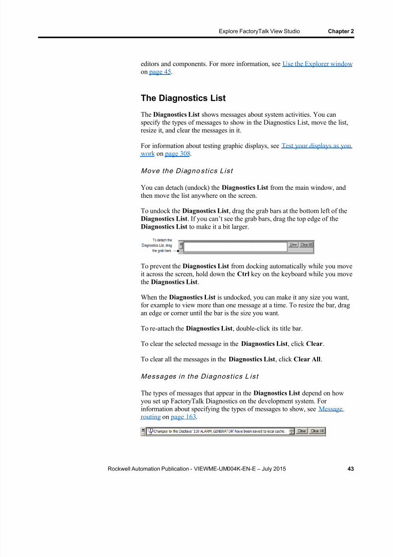
8/15/2019 Factory Talk View ME
http://slidepdf.com/reader/full/factory-talk-view-me 43/635
Explore FactoryTalk View Studio Chapter 2
Rockwell Automation Publication - VIEWME-UM004K-EN-E – July 2015 43
editors and components. For more information, see Use the Explorer window on page 45 .
The Diagnostics List
The Diagnostics List shows messages about system activities. You canspecify the types of messages to show in the Diagnostics List, move the list,resize it, and clear the messages in it.
For information about testing graphic displays, see Test your displays as youwork on page 308 .
Move the Diagno st ics Lis t
You can detach (undock) the Diagnostics List from the main window, andthen move the list anywhere on the screen.
To undock the Diagnostics List , drag the grab bars at the bottom left of theDiagnostics List . If you can’t see the grab bars, drag the top edge of theDiagnostics List to make it a bit larger.
To prevent the Diagnostics List from docking automatically while you moveit across the screen, hold down the Ctrl key on the keyboard while you movethe Diagnostics List .
When the Diagnostics List is undocked, you can make it any size you want,for example to view more than one message at a time. To resize the bar, dragan edge or corner until the bar is the size you want.
To re-attach the Diagnostics List , double-click its title bar.
To clear the selected message in the Diagnostics List , click Clear .
To clear all the messages in the Diagnostics List , click Clear All .
Messages in the Diagnost ics L is t
The types of messages that appear in the Diagnostics List depend on howyou set up FactoryTalk Diagnostics on the development system. Forinformation about specifying the types of messages to show, see Messagerouting on page 163 .

8/15/2019 Factory Talk View ME
http://slidepdf.com/reader/full/factory-talk-view-me 44/635
Chapter 2 Explore FactoryTalk View Studio
44 Rockwell Automation Publication - VIEWME-UM004K-EN-E – July 2015
The status bar
The status bar shows information about the active window or about theselected tool or menu item. The information that is shown depends on wherethe mouse pointer is. For example, when you select a graphic object in theGraphics editor, the status bar shows information about the selected object.
Workbook tabs
If you select Workbook Mode from the View menu, the workspace showstabs at the bottom for each open editor or component. Workbook Modeallows you to bring forward an open item more quickly than by using theWindow
menu.
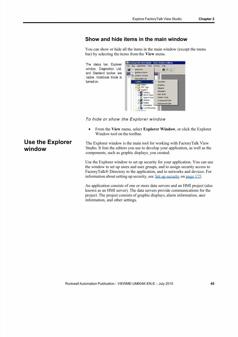
8/15/2019 Factory Talk View ME
http://slidepdf.com/reader/full/factory-talk-view-me 45/635
Explore FactoryTalk View Studio Chapter 2
Rockwell Automation Publication - VIEWME-UM004K-EN-E – July 2015 45
Show and hide items in the main window
You can show or hide all the items in the main window (except the menu bar) by selecting the items from the View menu.
To h ide o r show the Exp lo re r w indow
From the View menu, select Explorer Window , or click the ExplorerWindow tool on the toolbar.
The Explorer window is the main tool for working with FactoryTalk ViewStudio. It lists the editors you use to develop your application, as well as thecomponents, such as graphic displays, you created.
Use the Explorer window to set up security for your application. You can usethe window to set up users and user groups, and to assign security access to
FactoryTalk® Directory to the application, and to networks and devices. Forinformation about setting up security, see Set up security on page 175 .
An application consists of one or more data servers and an HMI project (alsoknown as an HMI server). The data servers provide communications for the
project. The project consists of graphic displays, alarm information, userinformation, and other settings.
Use the Explorerwindow

8/15/2019 Factory Talk View ME
http://slidepdf.com/reader/full/factory-talk-view-me 46/635
Chapter 2 Explore FactoryTalk View Studio
46 Rockwell Automation Publication - VIEWME-UM004K-EN-E – July 2015
This manual generally uses the term application to refer to bothapplication-level and project-level procedures.
View the Explorer window
You can view the Explorer window in a number of ways:
As a docked window. When docked, the explorer is always on top ofother windows that it overlaps. You can dock the explorer to any edgeof the main window.
As a floating window. When floating, the explorer is always on top ofother windows that it overlaps, but you can move it to differentlocations in the main window.
As a child window. When the explorer is in child mode, you canminimize the explorer or position other windows in front of it. This

8/15/2019 Factory Talk View ME
http://slidepdf.com/reader/full/factory-talk-view-me 47/635
Explore FactoryTalk View Studio Chapter 2
Rockwell Automation Publication - VIEWME-UM004K-EN-E – July 2015 47
mode is particularly useful when you are working in multiple editors orworking with the Help open.
To put the explorer in child mode, right-click the Explorer window title bar,
and then select MDI Child .
Move and resize the Explorer window
You can move the Explorer window in a number of ways:
Click the title bar and drag.
Right-click the title bar, then select a new docking location, floating, orchild mode.
You can resize the Explorer window by dragging its edges.
When developing an application, you will use many different editors, butthey have many similar features and often require similar information.Knowing how to use these features saves time.
For information on working with particular editors, see the chapters later inthis guide.
Locate editors
The editors are grouped in folders in the Explorer window (see Use theExplorer window on page 45 ). Each editor is shown with an icon to the leftof the editor name.
To open a fo lder in the Explorer windo w
Click the + symbol to the left of the folder icon, or double-click thefolder name.
Work with editors
8/15/2019 Factory Talk View ME
http://slidepdf.com/reader/full/factory-talk-view-me 48/635
Chapter 2 Explore FactoryTalk View Studio
48 Rockwell Automation Publication - VIEWME-UM004K-EN-E – July 2015
View an editor's components
With some editors you enter information in a single window or a tabbeddialog box. Other editors allow you to create multiple components, such asgraphic displays or message files. Each component is stored in a separatefile, with its own name.
You can create components in these editors:
Graphics (components include graphic displays, global objectdisplays, and graphic libraries, each in their own folder)
Alarms
Parameters
Local Messages
Information Messages
Data Log Models
Macros
RecipePlus
The Explorer window lists the components you create under the icon for theeditor you used to create the component.
Use the Images editor to copy bitmap images into your application (but not tocreate new images). Each image you copy is listed as a component under the
editor.
To v iew a li s t of comp onents for an edi tor
Click the + symbol to the left of the editor icon, or double-click theeditor name.
For information about working with components, see Work with components on page 294 .
Open editors
Use the editors in FactoryTalk View Studio to create or modify applicationcomponents. Editors are represented by icons in the Explorer window, or byitems in menus.
To open an edi tor
Use one of these methods:
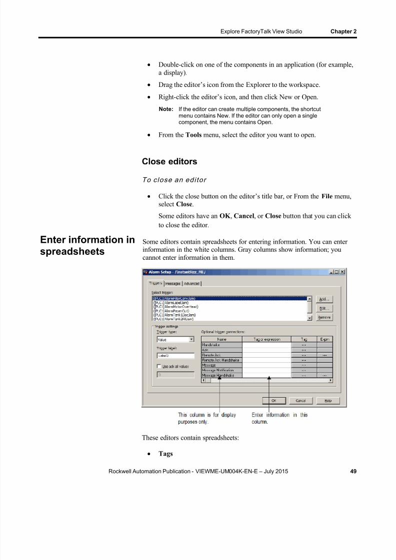
8/15/2019 Factory Talk View ME
http://slidepdf.com/reader/full/factory-talk-view-me 49/635

8/15/2019 Factory Talk View ME
http://slidepdf.com/reader/full/factory-talk-view-me 50/635
Chapter 2 Explore FactoryTalk View Studio
50 Rockwell Automation Publication - VIEWME-UM004K-EN-E – July 2015
Runtime Security (formerly User Accounts)
Global Connections
Local Messages
Alarm Setup
Information Setup
Information Messages
Macros
RecipePlus Editor
In the Graphics editor, many of the Properties dialog boxes for setting upgraphic objects contain spreadsheets for assigning tags or expressions to theobjects.
To enter information in a cell in a spreadsheet
Click the cell, and then type the information. If the cell alreadycontains text, the new information is added after the current text.
In the Property Panel , double-click the cell and then type theinformation. If the cell already contains text, double-clicking highlightsthe text and typing replaces the highlighted text.
To move to the next cell in the row
Press Tab or Enter .
The method to use depends on which editor you’re working in.
To move to the first cell in the next row
Press Enter or Down Arrow .
The method to use depends on which editor you are working in.
To delete a cell’s contents
Click the cell, and then press Delete or Backspace . PressingBackspace removes the characters one by one.
The method to use depends on which editor you are working in.

8/15/2019 Factory Talk View ME
http://slidepdf.com/reader/full/factory-talk-view-me 51/635
Explore FactoryTalk View Studio Chapter 2
Rockwell Automation Publication - VIEWME-UM004K-EN-E – July 2015 51
To delete rows
Select one or more rows, right-click the selection, and then selectDelete Rows .
Each component has a Print item on its File menu.
To print an editor’s contents
1. Open the component.
2. From the File menu, select Print .
3. Click OK .
Select a printer
You must install a printer before you can select it. For information aboutinstalling a printer, see your Windows documentation.
The Print Setup menu item in FactoryTalk View Studio applies to yourdevelopment computer only. To print at run time, set up a printer on thecomputer or PanelView Plus terminal you use to run your application. Formore information about printing at run time, see Print at run time on page 52 .
To select a printer
1. From the File menu in any editor or component, select Print Setup .
2. If you don’t want to use the default printer, specify another printer.
3. Choose the appropriate paper and orientation options.
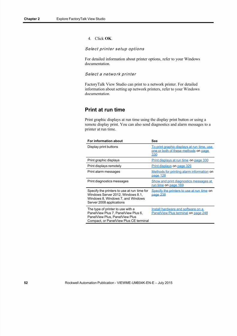
8/15/2019 Factory Talk View ME
http://slidepdf.com/reader/full/factory-talk-view-me 52/635
Chapter 2 Explore FactoryTalk View Studio
52 Rockwell Automation Publication - VIEWME-UM004K-EN-E – July 2015
4. Click OK .
Se lec t pr in ter se tup opt ions
For detailed information about printer options, refer to your Windowsdocumentation.
Selec t a ne two rk pr in ter
FactoryTalk View Studio can print to a network printer. For detailedinformation about setting up network printers, refer to your Windowsdocumentation.
Print at run time
Print graphic displays at run time using the display print button or using aremote display print. You can also send diagnostics and alarm messages to a
printer at run time.
For information about See
Display print buttons To print graphic displays at run time, useone or both of these methods on page330
Print graphic displays Print displays at run time on page 330
Print displays remotely Print displays on page 329
Print alarm messages Methods for printing alarm information onpage 128
Print diagnostics messages Show and print diagnostics messages atrun time on page 169
Specify the printers to use at run time forWindows Server 2012, Windows 8.1,Windows 8, Windows 7, and WindowsServer 2008 applications
Specify the printers to use at run time onpage 238
The type of printer to use with aPanelView Plus 7, PanelView Plus 6,PanelView Plus, PanelView PlusCompact, or PanelView Plus CE terminal
Install hardware and software on aPanelView Plus terminal on page 248

8/15/2019 Factory Talk View ME
http://slidepdf.com/reader/full/factory-talk-view-me 53/635
Rockwell Automation Publication - VIEWME-UM004K-EN-E – July 2015 53
Chapter 3
Plan applications
A well-designed application requires planning. To help you plan, this chapterdescribes:
Understand the machines and processes you’re automating
Collect data
Design an HMI tag database
Plan graphic displays and navigating between them Plan languages
Plan alarms
Provide information for the operator
Plan trends
Plan recipes
Design a secure system
FactoryTalk View comes with several sample applications that can give youguidance when planning your application. For instructions on opening thesample applications, see Open sample applications on page 40 .
Gather information from a variety of sources so you have a complete anddetailed understanding of the machines and processes you’re au tomating.
To gather information:
Talk to machine operators and other experts who are going to use thesystem. Find out what information they need to optimize machineoperations and processes.
Talk to management and management information systems staff to findout what information they need to support planning decisions.
Break up each section of the process into its constituent parts.
Determine what type of communications you’ll be using — whichnetwork types, data servers, and devices.
Determine which process variables you need to have access to andidentify their locations in the programmable controllers.
Understand theprocess

8/15/2019 Factory Talk View ME
http://slidepdf.com/reader/full/factory-talk-view-me 54/635
Chapter 3 Plan applications
54 Rockwell Automation Publication - VIEWME-UM004K-EN-E – July 2015
When planning data collection, design your system so only essential data iscollected. Limiting data collection is important because collection activitiesrequire substantial processing power and generate a lot of traffic on thenetwork.
Keep data collection requirements in mind when designing the layout of the programmable controller data tables and the HMI tag database. Ideally, tagaddresses reference contiguous blocks of programmable controller datatables to reduce highway traffic and optimize system response. If you’regoing to use data from an OPC server, read the server documentation to findout how to optimize traffic.
Take the time to plan your HMI tag database. A good design helps reducethe time required for maintenance and can improve programmablecontroller-to-FactoryTalk View response time.
For information about creating HMI tags, see Use HMI tags on page 97 .
Note: If you are going to use direct referencing for all your tags, youdon’ t need to create HMI tags in FactoryTalk View.Data Server tags usually update faster than HMI tags. Toobtain the best system performance for your application, useData Server tags where possible.
For information about creating Data Servers to data server tags, see Workwith tags on page 85 .
Collect informationBefore you begin creating the tag database, collect:
Flowcharts of your processes (or process and instrument diagrams).
A list of programmable controller data table or register addresses yourapplication will have access to.
Machinery systems documentation.
Alarm requirements (for more information, see Plan alarms on page58).
Organize tags
Before creating tags:
Develop naming conventions for tags, choosing names that are familiarand logical to everyone. This makes troubleshooting easier.
Group related tags.
Collect data
Design an HMI tagdatabase

8/15/2019 Factory Talk View ME
http://slidepdf.com/reader/full/factory-talk-view-me 55/635
Plan applications Chapter 3
Rockwell Automation Publication - VIEWME-UM004K-EN-E – July 2015 55
Group tags in the way that makes the most sense for your application.For example, group all similar devices or group related areas of the
plant floor.
When creating tags, place related tags into folders. For greaterorganization, nest folders.
When planning displays, determine the best way for users to navigatethrough your displays and develop a template to establish a common lookand feel for your displays.
Also consider factors about the runtime terminal that affect how theapplication is shown and used, such as:
Screen size
The maximum number of displays supported at run time If the applications runs on a personal computer, the maximum number
of displays is based on the type of activation used
If the application runs on PanelView Plus, the maximum number ofdisplays is based on the amount of memory used by the application.Applications run on a PanelView Plus can contain as many displays ascan fit in the memory of the PanelView Plus terminal.
PanelView Plus 7 Standard applications, and Compact MachineEdition applications have a limit of 25 displays.
Whether the operator will be using a keyboard, touch screen, mouse, or
combination of navigation and data entry methods.For information about creating graphic displays, see Use graphic displays on
page 299 .
Develop a hierarchy of displays
A hierarchy of displays is a series of graphic displays that provide progressively more detail as users move through them. Design your displayhierarchy to meet the needs of the various users, including managers,supervisors, and operators.
Well-organized graphic displays present information clearly and consistentlyand guide users through the system. Before designing individual graphicdisplays, plan an overall display hierarchy and plan how users will navigatethrough the hierarchy.
For information about navigation methods and developing a hierarchy ofdisplays, see Set up global connections on page 111 .
Plan graphicdisplays
8/15/2019 Factory Talk View ME
http://slidepdf.com/reader/full/factory-talk-view-me 56/635
Chapter 3 Plan applications
56 Rockwell Automation Publication - VIEWME-UM004K-EN-E – July 2015
Create a template to ensure consistency
It is possible to keep a consistent appearance among all the displays in anapplication by presenting the same pieces of information in the same placeon each graphic display. To ensure uniformity, develop a display withcommon elements that acts as a template. Each time you develop a newdisplay, start with a duplicate of the template.
For example, the template could contain:
Your company logo.
A title.
The date and time.
Navigational buttons.
Use global object displays to create template objects. You can copy theobjects into your graphic displays, and update all the objects at once byupdating the original object in the global object display. For informationabout creating global object displays, see Create global object displays and
base objects on page 510 .
Design displays
When designing displays, applying good visual design principles helps usersand increases their efficiency.
Remember these important design principles:
Consistency
Be consistent with your use of symbols and color.
Be consistent with button labels and button placement.
When you design several displays, place the same kinds of buttons inthe same positions. For example, if you have a Start button in a certain
position in one display, don’t put a Stop button in the sa me position inthe next display.
Clarity
Use symbols that are easily recognizable. For example, use theconventional ISA symbols for tanks and valves.
Don’t overload the screen with information.
Use standard, clear terminology, and avoid abbreviations or acronymsthat the user might not understand.
8/15/2019 Factory Talk View ME
http://slidepdf.com/reader/full/factory-talk-view-me 57/635
Plan applications Chapter 3
Rockwell Automation Publication - VIEWME-UM004K-EN-E – July 2015 57
Use colors with recognizable meanings. For example, in NorthAmerica the colors red and green usually mean stop and start. Keepcolor meanings consistent by assigning red only to Stop buttons, andgreen only to Start buttons.
Some people are color blind to red and green so don’t rely on coloralone to establish meaning.
Use high contrast color combinations, such as yellow on blue.
Display types
On Top display type is used to position the display in front of any otherdisplay that is already open at runtime.
Replace display type is used to have the display close any opendisplays on the screen at runtime. Replace displays do not close
displays of the type On Top that have the Cannot Be Replaced optionselected. Only one Replace display can be open at a time.
Usability
If you’re designing for a touch screen, don’t place important buttonswhere they’ll be blocked by an On Top display. The user can’ t press acovered button. Also, ensure the button is large enough for users totouch easily.
Ensure there is always a clear way to move between displays.
Keep the intended user in mind and design displays so they are easy to
understand and use. Ask the users to test the displays.
Before setting up languages, plan:
Which languages you need to use
Which Windows fonts support these languages
For applications running on a personal computer which Windowsfonts support these languages
For applications running on a PanelView Plus terminal whichlanguages the fonts resident on the terminal support
How different languages will affect design elements in your graphicdisplays, such as object size and message length
Whether operators need to switch languages at run time, and if so,under what conditions. This will help you determine where to locateLanguage Switch buttons in your application
How to show operators which button to press to switch to theirlanguages. For example, by using a text label in French, or a Frenchflag, to alert a French operator
Plan languages
8/15/2019 Factory Talk View ME
http://slidepdf.com/reader/full/factory-talk-view-me 58/635

8/15/2019 Factory Talk View ME
http://slidepdf.com/reader/full/factory-talk-view-me 59/635
Plan applications Chapter 3
Rockwell Automation Publication - VIEWME-UM004K-EN-E – July 2015 59
Analyze process trends?
Monitor production efficiency?
Archive process variables to ensure compliance with governmentregulations?
Based on such considerations, you can determine:
Which tags need to be plotted on the same trend.
Which tags need to be logged by using a data log model.
For information about setting up data logging, see Set up data logging on page 519 .
For information about creating trend graphic objects, see Set up trends on page 535 .
When planning recipes, consider how they will be used. For example, willrecipes be used to:
Compare tag values to pre-set data values?
Upload tag values to existing or new data sets?
Download values from data sets to tags?
Archive tag values to ensure compliance with government regulations?
Based on such considerations, you can determine:
Which tag sets and data sets to pair together in a recipe file.
Which RecipePlus button actions to use with the RecipePlus selectorand RecipePlus table.
For information about using recipes and creating RecipePlus graphic objects,see Set upi ReciplePlus on page 547 .
When deciding on your security requirements, consider whether to:
Restrict access to every graphic display to prevent accidental changes.
Restrict access to certain graphic displays. Have everyone log on.
Use passwords, and if so, whether to have a minimum length, andwhether to require that the passwords are changed periodically.
Allow only authorized users to shut down the application.
Use the DeskLock tool on Windows platforms to prevent users fromswitching to another application at run time (for applications that will
Plan recipes
Design a securesystem

8/15/2019 Factory Talk View ME
http://slidepdf.com/reader/full/factory-talk-view-me 60/635
Chapter 3 Plan applications
60 Rockwell Automation Publication - VIEWME-UM004K-EN-E – July 2015
run on personal computers). You can use this tool to set up acustomized desktop and to prevent access to Windows® functions.
Based on these considerations, you can set up security for individual users or
groups of users. For example, you might want to set up groups of users suchas a manager group and an operator group.
For more information about setting up security, see Set up security on page175 .

8/15/2019 Factory Talk View ME
http://slidepdf.com/reader/full/factory-talk-view-me 61/635
Rockwell Automation Publication - VIEWME-UM004K-EN-E – July 2015 61
Chapter 4
Work with applications
This chapter describes:
Application files
Create, import, open, and close applications
Rename, copy, delete, back up, and restore applications
Specify project settings
View application properties
View HMI server properties
An application is the software application you create in FactoryTalk ViewStudio to monitor and control your plant processes. An application consistsof one or more data servers and an HMI project (also known as an HMIserver). The data servers provide communications for the project. The projector HMI server consists of graphic displays, alarm information, userinformation, and other settings.
For information about viewing the application properties, see View
application properties on page 77 . For information about viewing the HMIserver properties, see View HMI server properties on page 77 .
Application versus project
This manual generally uses the term application to refer to bothapplication-level and project-level procedures. There is an exception onusing the Project Settings editor. See About project settings on page 72 . Inthat section, the term project is used.
When you create an application, FactoryTalk View creates folders and filesin various locations on the development computer. Some of the folders areempty until you start setting up your application. When you finishdeveloping the application, FactoryTalk View uses the information in thevarious folders and files to create the runtime application.
What is anapplication?
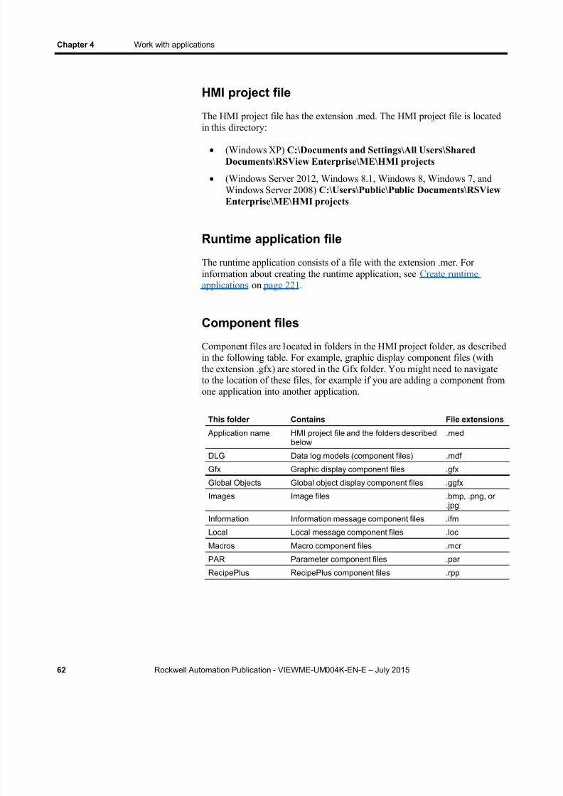
8/15/2019 Factory Talk View ME
http://slidepdf.com/reader/full/factory-talk-view-me 62/635
Chapter 4 Work with applications
62 Rockwell Automation Publication - VIEWME-UM004K-EN-E – July 2015
HMI project file
The HMI project file has the extension .med. The HMI project file is locatedin this directory:
(Windows XP) C:\Documents and Settings\All Users\SharedDocuments\RSView Enterprise\ME\HMI projects
(Windows Server 2012, Windows 8.1, Windows 8, Windows 7, andWindows Server 2008) C:\Users\Public\Public Documents\RSViewEnterprise\ME\HMI projects
Runtime application file
The runtime application consists of a file with the extension .mer. Forinformation about creating the runtime application, see Create runtimeapplications on page 221 .
Component files
Component files are located in folders in the HMI project folder, as describedin the following table. For example, graphic display component files (withthe extension .gfx) are stored in the Gfx folder. You might need to navigateto the location of these files, for example if you are adding a component fromone application into another application.
This folder Contains File extensions
Application name HMI project file and the folders describedbelow
.med
DLG Data log models (component files) .mdf
Gfx Graphic display component files .gfx
Global Objects Global object display component files .ggfx
Images Image files .bmp, .png, or.jpg
Information Information message component files .ifm
Local Local message component files .loc
Macros Macro component files .mcrPAR Parameter component files .par
RecipePlus RecipePlus component files .rpp

8/15/2019 Factory Talk View ME
http://slidepdf.com/reader/full/factory-talk-view-me 63/635
Work with applications Chapter 4
Rockwell Automation Publication - VIEWME-UM004K-EN-E – July 2015 63
External folders
The following table lists some FactoryTalk View folders that are external tothe HMI project folder, and the types of files they contain.
The folders are located in this directory:
(Windows XP) C:\Documents and Settings\All Users\SharedDocuments\RSView Enterprise
(Windows Server 2012, Windows 8.1, Windows 8, Windows 7, andWindows Server 2008) C:\Users\Public\PublicDocuments\RSViewEnterprise
This folder Contains File extensions
Images Image files for use on graphic objects .bmpME\Archives ME archive application files .apa
ME\Libraries Graphic library component files andimage files used in the library displays
.gfx
.bmp
ME\Logs\ Runtime Application Name \Dlglog\ Data Log ModelName
Data log files for applications that haverun on the development computer
.log
.tag
ME\Logs\ Runtime Application Name \M_Alarms
Alarm log file for applications that haverun on the development computer
.alm
ME\Runtime Runtime application files .mer
ME\HMI projects Sample application folders, including allfiles and folders needed for the sample
ME\Faceplates Graphic displays and global objectdisplays for Logix5000 faceplates
.gfx
.ggfx
.bmp
If desired, you can specify a different directory in which to store graphiclibrary component files. For more information, see Location of librarycomponents on page 318 .
Default log file locations for PanelView Plus 7,PanelView Plus 6, PanelView Plus, or PanelViewPlus CE applications
On the PanelView Plus 7 or PanelView Plus 6 terminal, alarm and data logfolders are located by default in this directory:
\Windows\Logs
8/15/2019 Factory Talk View ME
http://slidepdf.com/reader/full/factory-talk-view-me 64/635
Chapter 4 Work with applications
64 Rockwell Automation Publication - VIEWME-UM004K-EN-E – July 2015
On the PanelView Plus or PanelView Plus CE terminal, the alarm and datalog folders are located by default in this directory
\Storage Card\Rockwell Software\RSViewME\Logs
Data log f i le loca t ions
You can also store data log files in a different location on the runtimecomputer, on a networked computer, or on a PC card. For more information,see Set up data logging on page 519 .
Name files
File names, including the path, can be up to 200 characters long (file names
can contain spaces). For example, the following path and file name contains119 characters:
C:\Documents and Settings\All Users\Documents\RSViewEnterprise\ME\HMI projects\Malthouse Clgx640x480\Gfx\Steeping.gfx
Creat applications
You can create a new application when you start FactoryTalk View Studio,or once FactoryTalk View Studio is already open.
Creat, import, open,and closeapplications
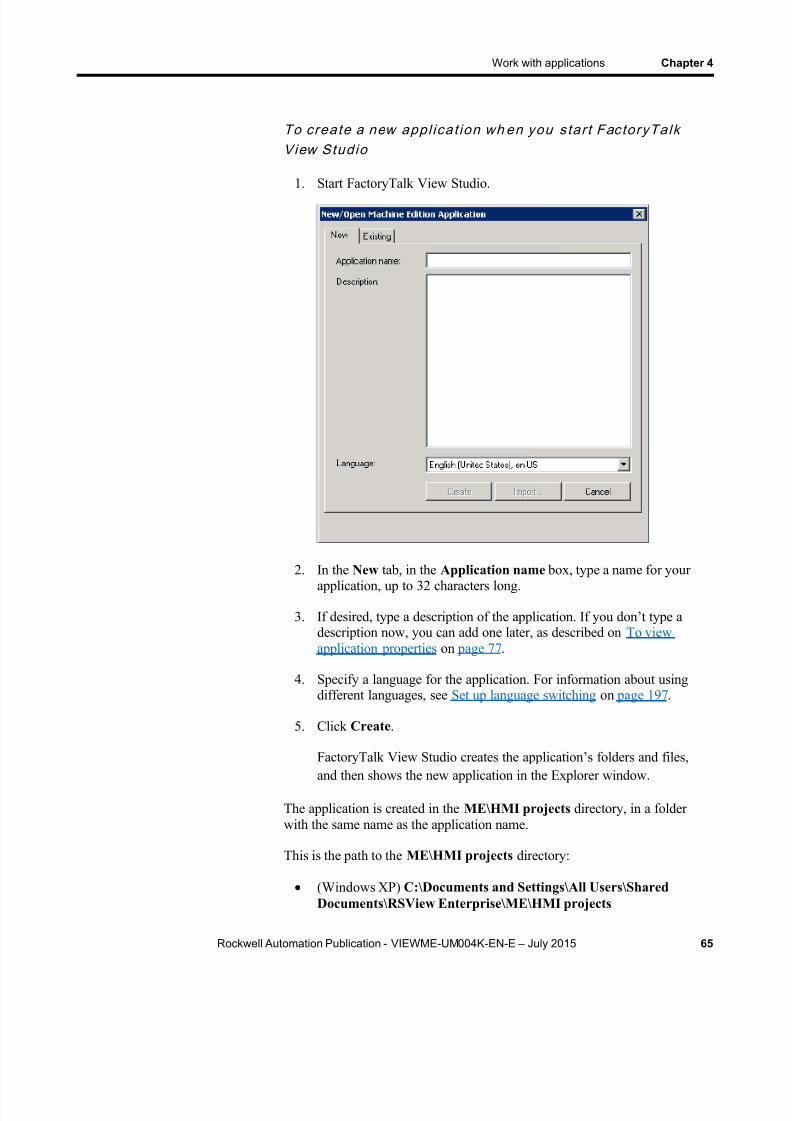
8/15/2019 Factory Talk View ME
http://slidepdf.com/reader/full/factory-talk-view-me 65/635
Work with applications Chapter 4
Rockwell Automation Publication - VIEWME-UM004K-EN-E – July 2015 65
To crea te a new appl ica t ion wh en you s tar t FactoryTalkView Studio
1. Start FactoryTalk View Studio.
2. In the New tab, in the Application name box, type a name for yourapplication, up to 32 characters long.
3. If desired, type a description of the application. If you don’t type adescription now, you can add one later, as described on To viewapplication properties on page 77 .
4. Specify a language for the application. For information about usingdifferent languages, see Set up language switching on page 197 .
5. Click Create .
FactoryTalk View Studio creates the application’s folders and files,and then shows the new application in the Explorer window.
The application is created in the ME\HMI projects directory, in a folderwith the same name as the application name.
This is the path to the ME\HMI projects directory:
(Windows XP) C:\Documents and Settings\All Users\SharedDocuments\RSView Enterprise\ME\HMI projects
8/15/2019 Factory Talk View ME
http://slidepdf.com/reader/full/factory-talk-view-me 66/635
Chapter 4 Work with applications
66 Rockwell Automation Publication - VIEWME-UM004K-EN-E – July 2015
(Windows Server 2012, Windows 8.1, Windows 8, Windows 7, andWindows Server 2008) C:\Users\Public\Public Documents\RSViewEnterprise\ME\HMI projects
Once you create the application, the system automatically creates a displaycalled MAIN and sets the Projects Settings , startup Graphic to Main. Thesesettings determine the general appearance of your runtime application, andaffect how your graphic displays look. For more information, see Specify
project settings on page 76 .
To crea te a new appl ica t ion wh en FactoryTalk View Studiois a l ready o pen
1. From the File menu, select New Application , or click the New
Application tool .
If an application is already open, FactoryTalk View Studio asks youwhether to close the application that is currently open. Click Yes .
2. Follow steps 2 through 5 in the previous procedure.
Import applications
You can import PanelBuilder, PanelBuilder32, PanelBuilder 1400e, andFactoryTalk View Machine Edition applications into FactoryTalk View
Studio.PanelBuilder and PanelBuilder32 files can be in either development format(*.pba) or runtime terminal format (*.pva). PanelBuilder 1400e files have thefile extension *.pvc.
When you import older application files, FactoryTalk View creates a copy ofthe application for the current version of FactoryTalk View. The olderversion is not altered.
You can use current version application files to create previous versionruntime files. For more information, see Open and edit applications fromearlier versions of RSView or FactoryTalk View ME on page 70 .
If the application you are importing contains any direct driver nodes, theimport wizard will create one RSLinx topic for each direct driver node itfinds. All topics are then converted into device shortcuts, to run with RSLinxEnterprise. You must have both RSLinx Classic and RSLinx Enterpriseinstalled to make this two-step conversion.
To create RSLinx topics after import, follow these steps in RSLinx beforeimporting the application.
8/15/2019 Factory Talk View ME
http://slidepdf.com/reader/full/factory-talk-view-me 67/635
Work with applications Chapter 4
Rockwell Automation Publication - VIEWME-UM004K-EN-E – July 2015 67
To val ida te d i rec t d r iver nodes in RSLinx
1. Create the appropriate RSLinx Classic drivers if not already created(for example, AB_ETH-1).
2. For more information about creating RSLinx Classic drivers, see theRSLinx Classic Help.
3. If it is an Ethernet driver (AB_ETH-1), add the IP address of eachdirect driver node to the Ethernet driver setup.
4. Start RSWho and select each device associated with each direct drivernode (for example, 131.200.13.128).
5. If these steps are not followed in this order, the topics generated by theimport code will be invalid and will need to be fixed using the Topic
Editor in RSLinx.
To impor t an appl ica t ion
1. Start FactoryTalk View Studio
2. In the New tab, in the Application name box, type a name for theimported application, up to 32 characters long.
3. If desired, type a description of the application. If you don’t type adescription now, you can add one later, as described on To viewapplication properties on page 77 .
4. Specify a language for the application. For information about usingmultiple languages, see Set up language switching on page 197 .
5. Click Import . The Machine Edition Import Wizard opens.
6. Follow the directions in the Machine Edition Import Wizard.
7. For more information about importing PanelBuilder 1400eapplications, see Convert PanelBuilder 1400e applications on page565 .
For more information about importing PanelBuilder andPanelBuilder32 applications, see Convert PanelBuilder andPanelBuilder32 applications on page 581 .
Open applications
You can open an application when you start FactoryTalk View Studio, oronce FactoryTalk View Studio is already open.

8/15/2019 Factory Talk View ME
http://slidepdf.com/reader/full/factory-talk-view-me 68/635
8/15/2019 Factory Talk View ME
http://slidepdf.com/reader/full/factory-talk-view-me 69/635
Work with applications Chapter 4
Rockwell Automation Publication - VIEWME-UM004K-EN-E – July 2015 69
FactoryTalk View Studio shows the application in the Explorerwindow.
To open an exis t ing appl ica t ion wh en FactoryTalk ViewStudio i s a l ready open
1. From the File menu, select Open Application , or click the OpenApplication tool .
2. If an application is already open, FactoryTalk View Studio asks youwhether to close the application that is currently open. Click Yes .
3. Follow steps 2 through 4 in the previous procedure.
To open an appl ica t ion yo u used recent ly
1. From the File menu, select Recent Applications , and then click thename of the application to open.
2. If an application is already open, FactoryTalk View Studio asks youwhether to close the application that is currently open. Click Yes .
The application opens. For applications with multiple languages, thelanguage you used most recently opens. For information about usingdifferent languages, see Set up language switching on page 197 .
Problems opening appl ica t ions
If you have trouble opening an application in FactoryTalk View Studio, the problem could be a Microsoft Windows security setting. You must have readand write access to the folder that contains the HMI projects. For example, ifyou belong to the Windows user group called Power Users, and the groupdoes not have write access to the HMI projects folder, you won’t be able toopen applications in FactoryTalk View.
The default location for the HMI projects folder is:
(Windows XP) C:\Documents and Settings\All Users\SharedDocuments\RSView Enterprise\ME
(Windows Server 2012, Windows 8.1, Windows 8, Windows 7, andWindows Server 2008) C:\Users\Public\Public Documents\RSViewEnterprise\ME
For more information about security, see Set up security on page 175 .
To se t up wri te access for any Windo ws Secur i ty Group
1. Right-click the HMI projects folder, and then select Properties .

8/15/2019 Factory Talk View ME
http://slidepdf.com/reader/full/factory-talk-view-me 70/635
Chapter 4 Work with applications
70 Rockwell Automation Publication - VIEWME-UM004K-EN-E – July 2015
2. In the Security tab of the Properties dialog box, select a WindowsSecurity Group (for example, Power Users) from the list of groups anduser names.
3. In the Permissions box below the list, select Full Control , and thenselect Allow .
Open multiple applications
To open two applications at the same time, for example to copy images andgraphic objects between applications, start two instances of FactoryTalkView Studio.
Note: To view a graphic display in different languages at the same time, openthe application multiple times, selecting a different language each time youopen it.
Open and edit applications from earlier versions ofRSView or FactoryTalk View ME
You can open and edit applications from RSView 3.10, 3.20, andFactoryTalk View 4.0, 5.0, 6.0, 6.10, 7.0, and 8.0. When you are finishedediting, you can create runtime application files for ME Station version 3.10,3.20, 4.0,5.0, 5.10, 6.0, 6.10, 7.0, and 8.0. This allows you to continuerunning your applications on existing terminals, without upgrading all your
software.
The application is converted to the current version of FactoryTalk Viewwhen you import it, but when you create the runtime application file you cansave it back to the earlier version.
If the application uses a feature that is not supported by the runtime version,you will not be able to create the runtime application file. The exceptions aremultiple languages, and global objects. When you create the runtimeapplication file, it uses the application’s current language. You can create asmany different runtime application files, in as many different languages, asyou want. However, the language switch feature is not available at run time
for version 3.10, and 3.20 applications. Global objects are converted toregular objects in the runtime application file for versions 3.10, and 3.20.
For information about importing applications, see Import applications on page 66 .
For information about the features supported in different versions ofFactoryTalk View and RSView, see Features supported in different versionsof FactoryTalk View on page 605 .
8/15/2019 Factory Talk View ME
http://slidepdf.com/reader/full/factory-talk-view-me 71/635
Work with applications Chapter 4
Rockwell Automation Publication - VIEWME-UM004K-EN-E – July 2015 71
For information about using multiple languages, see Set up languageswitching on page 197 .
For information about using global objects, see Use graphic displays on page
299 .Panel
Close applications
To c lose an appl ica t ion
From the File menu, select Close Application .
If there are any unsaved changes in open editors, FactoryTalk ViewStudio asks you whether to save the changes before closing theapplication.
To c lose an appl ica t ion and exi t FactoryTalk View Studio a tthe same t ime
Click the Close button at the right end of the FactoryTalk View Studiotitle bar .
If there are any unsaved changes in open editors, FactoryTalk ViewStudio asks you whether to save the changes before closing.
Use the Application Manager tool to:
Rename applications
Copy applications
Delete applications
Create a compressed backup copy of an application, with the fileextension .apa
Restore an application from the backup file, with the file extension .apa
Restore a legacy project backup file (with the file extension .mea) froman earlier release of FactoryTalk View Studio, and convert it to thecurrent version
Restore a runtime application file, with the file extension .mer, to adevelopment application, with the file extension .med. For moreinformation, see Convert runtime application files to developmentapplications on page 226 .
Rename, copy,delete, back up, andrestore applications
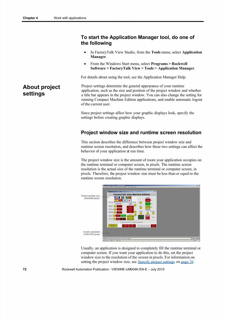
8/15/2019 Factory Talk View ME
http://slidepdf.com/reader/full/factory-talk-view-me 72/635
Chapter 4 Work with applications
72 Rockwell Automation Publication - VIEWME-UM004K-EN-E – July 2015
To start the Application Manager tool, do one ofthe following
In FactoryTalk View Studio, from the Tools menu, select ApplicationManager .
From the Windows Start menu, select Programs > RockwellSoftware > FactoryTalk View > Tools > Application Manager .
For details about using the tool, see the Application Manager Help.
Project settings determine the general appearance of your runtimeapplication, such as the size and position of the project window and whethera title bar appears in the project window. You can also change the setting forrunning Compact Machine Edition applications, and enable automatic logoutof the current user.
Since project settings affect how your graphic displays look, specify thesettings before creating graphic displays.
Project window size and runtime screen resolution
This section describes the difference between project window size andruntime screen resolution, and describes how these two settings can affect the
behavior of your application at run time.
The project window size is the amount of room your application occupies onthe runtime terminal or computer screen, in pixels. The runtime screenresolution is the actual size of the runtime terminal or computer screen, in
pixels. Therefore, the project window size must be less than or equal to theruntime screen resolution.
Usually, an application is designed to completely fill the runtime terminal orcomputer screen. If you want your application to do this, set the projectwindow size to the resolution of the screen in pixels. For information onsetting the project window size, see Specify project settings on page 76 .
About projectsettings

8/15/2019 Factory Talk View ME
http://slidepdf.com/reader/full/factory-talk-view-me 73/635

8/15/2019 Factory Talk View ME
http://slidepdf.com/reader/full/factory-talk-view-me 74/635
Chapter 4 Work with applications
74 Rockwell Automation Publication - VIEWME-UM004K-EN-E – July 2015
Reposition the [ALARM] display from the default position (0, 0), asthis position is below the viewing area of the terminals.
Change the projec t wind ow s ize af ter c rea t ing graphicdisplays
The project window size is used for all graphic displays of the Replace type.If you change the window size after you have already created graphicdisplays, you have the option of scaling graphic displays.
If you choose to scale graphic displays, all Replace and On Top displays areresized and the objects in them are scaled to fit the new size. You can alsospecify whether to scale the font size and border size of the graphic objects,and the size of graphic images in the Images folder.
If you choose not to scale displays when you change the project window size,Replace displays are resized, but any objects in the displays remain the samesize and in the same position as before. On Top displays are not resized.
For more information about Replace and On Top displays, see About displaytypes on page 310 . For more information about scaling displays, see Help.
How the run t ime screen resolu t ion affec ts the pop -upw i n d o w s
FactoryTalk View comes with a pop-up Login window, as well as numericand string pop-up windows for runtime data entry, and a Change Password
window for changing user passwords at run time.

8/15/2019 Factory Talk View ME
http://slidepdf.com/reader/full/factory-talk-view-me 75/635
Work with applications Chapter 4
Rockwell Automation Publication - VIEWME-UM004K-EN-E – July 2015 75
How the p rojec t windo w s ize affec ts th e defaul t messagedisplays
Your application comes with pre-configured, default graphic displays fordiagnostics, alarm, and information messages. If the project window size issmaller than the default displays, the edges of the displays are cut off at runtime.
These are the sizes of the default displays:
Graphic Display Width in pixels Height in pixels
[DIAGNOSTICS] 640 160
[ALARM] 640 210
[INFORMATION] 640 80
If your project window size is smaller than the default message display sizes,you can resize the default displays, or use your own displays instead.
PanelView Plus 7 Standard applications andCompact Machine Edition applications
Applications intended for PanelView Plus 7 Standard, PanelView Plus 6Compact, and PanelView Plus Compact terminals have certain restrictions,such as the number of displays and alarm messages supported.
To change an application to a PanelView Plus 7 Standard application, or aCompact Machine Edition application (application running on PanelViewPlus 6 Compact, or PanelView Plus Compact terminals), in the the Generaltab of the Project Settings dialog box, from the Project window size list,select a PVPlus Compact , or a PVPlus 7 Standard option.
Title bar
If you select this option, a title bar is used for all Replace graphic displays.For information about graphic display types, see About display types on page
310 . If desired, you can also use a Control box, Minimize button, and Close
button on the title bar. The Close button appears only if you select theControl box in the Project Settings editor.
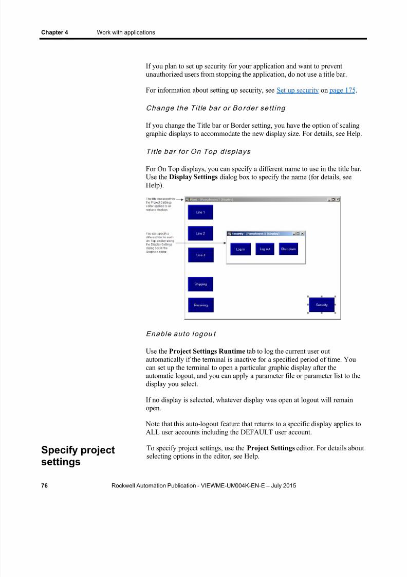
8/15/2019 Factory Talk View ME
http://slidepdf.com/reader/full/factory-talk-view-me 76/635
Chapter 4 Work with applications
76 Rockwell Automation Publication - VIEWME-UM004K-EN-E – July 2015
If you plan to set up security for your application and want to preventunauthorized users from stopping the application, do not use a title bar.
For information about setting up security, see Set up security on page 175 .
Change the Ti t le bar or Bo rder se t t ing
If you change the Title bar or Border setting, you have the option of scalinggraphic displays to accommodate the new display size. For details, see Help.
Ti t le bar for On Top displays
For On Top displays, you can specify a different name to use in the title bar.Use the Display Settings dialog box to specify the name (for details, seeHelp).
Enable auto logou t
Use the Project Settings Runtime tab to log the current user outautomatically if the terminal is inactive for a specified period of time. Youcan set up the terminal to open a particular graphic display after theautomatic logout, and you can apply a parameter file or parameter list to thedisplay you select.
If no display is selected, whatever display was open at logout will remainopen.
Note that this auto-logout feature that returns to a specific display applies toALL user accounts including the DEFAULT user account.
To specify project settings, use the Project Settings editor. For details aboutselecting options in the editor, see Help.
Specify projectsettings

8/15/2019 Factory Talk View ME
http://slidepdf.com/reader/full/factory-talk-view-me 77/635
Work with applications Chapter 4
Rockwell Automation Publication - VIEWME-UM004K-EN-E – July 2015 77
You can view this information about your application:
Application name
Application description, if any
To view application properties
From the Application menu, select Application Properties .
You can use the Explorer window to view this information about your project or HMI server:
Application name
View applicationproperties
View HMI serverproperties
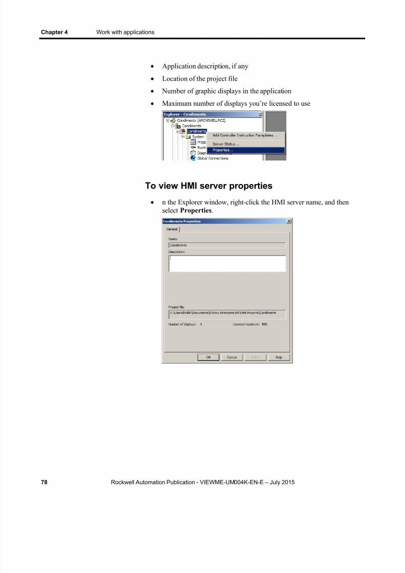
8/15/2019 Factory Talk View ME
http://slidepdf.com/reader/full/factory-talk-view-me 78/635
Chapter 4 Work with applications
78 Rockwell Automation Publication - VIEWME-UM004K-EN-E – July 2015
Application description, if any
Location of the project file
Number of graphic displays in the application
Maximum number of displays you’re licensed to use
To view HMI server properties
n the Explorer window, right-click the HMI server name, and thenselect Properties .
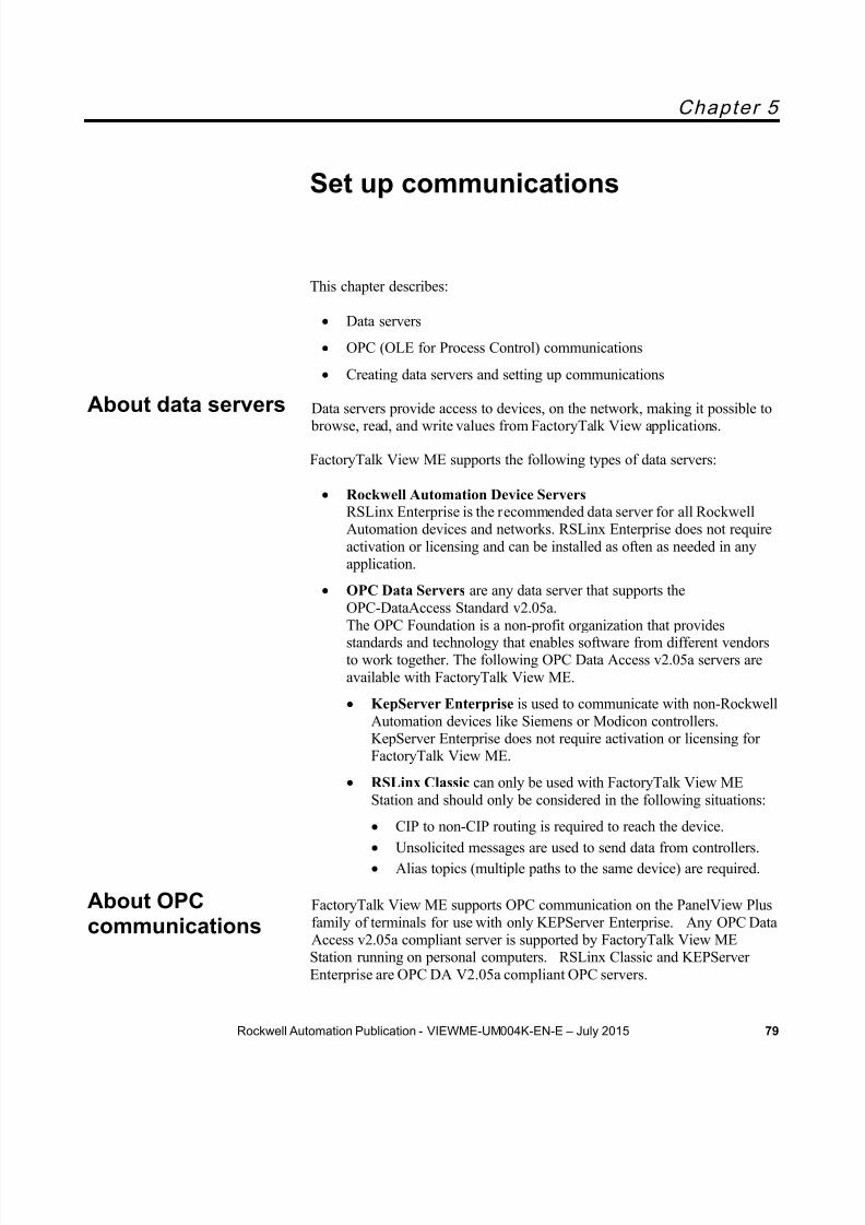
8/15/2019 Factory Talk View ME
http://slidepdf.com/reader/full/factory-talk-view-me 79/635
Rockwell Automation Publication - VIEWME-UM004K-EN-E – July 2015 79
Chapter 5
Set up communications
This chapter describes:
Data servers
OPC (OLE for Process Control) communications
Creating data servers and setting up communications
Data servers provide access to devices, on the network, making it possible to browse, read, and write values from FactoryTalk View applications.
FactoryTalk View ME supports the following types of data servers:
Rockwell Automation Device Servers RSLinx Enterprise is the recommended data server for all RockwellAutomation devices and networks. RSLinx Enterprise does not requireactivation or licensing and can be installed as often as needed in anyapplication.
OPC Data Servers are any data server that supports theOPC-DataAccess Standard v2.05a.
The OPC Foundation is a non-profit organization that providesstandards and technology that enables software from different vendorsto work together. The following OPC Data Access v2.05a servers areavailable with FactoryTalk View ME.
KepServer Enterprise is used to communicate with non-RockwellAutomation devices like Siemens or Modicon controllers.KepServer Enterprise does not require activation or licensing forFactoryTalk View ME.
RSLinx Classic can only be used with FactoryTalk View MEStation and should only be considered in the following situations:
CIP to non-CIP routing is required to reach the device. Unsolicited messages are used to send data from controllers. Alias topics (multiple paths to the same device) are required.
FactoryTalk View ME supports OPC communication on the PanelView Plusfamily of terminals for use with only KEPServer Enterprise. Any OPC DataAccess v2.05a compliant server is supported by FactoryTalk View MEStation running on personal computers. RSLinx Classic and KEPServerEnterprise are OPC DA V2.05a compliant OPC servers.
About data servers
About OPCcommunications

8/15/2019 Factory Talk View ME
http://slidepdf.com/reader/full/factory-talk-view-me 80/635
Chapter 5 Set up communications
80 Rockwell Automation Publication - VIEWME-UM004K-EN-E – July 2015
An RSLinx Enterprise data server is created automatically with a newapplication. It is located under the application’s HMI server in the Explorerwindow, just above the FactoryTalk System folder.
You can create additional OPC data servers for your application. Forexample, you might want to use an RSLinx Enterprise data server and aKEPServer Enterprise data server to communicate with a third party device.
Set up RSLinx Enterprise data servers
You can use the Communication Setup editor to add drivers, add devices,set up driver and device properties, and set up device shortcuts.
To se t up co mm unicat ions in RSLinx Enterpr ise
1. In the Explorer window, open the RSLinx Enterprise data server.
2. Double-click the Communication Setup editor.
3. In a new application, the RSLinx Enterprise Configuration Wizardopens. Follow the instructions to create a new configuration or use anexisting device configuration. Once you make a choice and clickFinish , the Communication Setup editor opens.
In an existing application, double-clicking Communication Setup opens theCommunication Setup editor, with its two tabs.
The Design (Local) tab is for establishing the location of the tags/addressesfor editing. The tags/addresses can be online with a controller or other dataserver, or an offline controller file. This will enable the Tag Browser to findthe tags/addresses.
The Runtime (Target) tab is for identifying the connection from the runtimecomputer or terminal to the controller or other data server. If the paths are the
Create data servers

8/15/2019 Factory Talk View ME
http://slidepdf.com/reader/full/factory-talk-view-me 81/635
Set up communications Chapter 5
Rockwell Automation Publication - VIEWME-UM004K-EN-E – July 2015 81
same, use the Copy button to copy the Design configuration to the Runtime tab.
For more information, see Help for RSLinx Enterprise.
Set up an OPC data server
Use a KEPServer Enterprise data server if you need to connect third partydevices.
Use RSLinx Classic data server if you have one of the situations describedabove and you are using a personal computer in your application.
If you need to view or use tag names when you are not connected to a device,you can setup a cache that will read in tag names from the device and enablethem to be used when the device is offline.
To create an OPC data server
In the Explorer window, right-click the application, select Add NewServer , and then click OPC Data Server .
For details about selecting options in the OPC Data Server Properties dialog box, see FactoryTalk View Machine Edition Help.

8/15/2019 Factory Talk View ME
http://slidepdf.com/reader/full/factory-talk-view-me 82/635
Chapter 5 Set up communications
82 Rockwell Automation Publication - VIEWME-UM004K-EN-E – July 2015
Update data server caches
If tags are added, modified, or deleted on the data server, you must update(synchronize) the cache manually.
For information about updating the data server cache periodically after youcreate it, see FactoryTalk View Machine Edition Help.
For information about editing and removing data servers, see FactoryTalkView Machine Edition Help.
Follow these steps to:
Install hardware and software on a PanelView Plus 7, PanelView Plus6, PanelView Plus, PanelView Plus Compact, or PanelView Plus CEterminal.
Transfer your application to the PanelView Plus 7, PanelView Plus 6,PanelView Plus, PanelView Plus Compact, or PanelView Plus CEterminal.
For information about installing FactoryTalk View ME Station, see the FactoryTalk View Machine Edition Installation Guide .
1. Gather information about your network, and the devices that areconnected to it. You will need this information to set up RSLinxEnterprise, KEPServer Enterprise, RSLinx Classic, or another OPCserver. Do one of the following:
If you want to use KEPServer Enterprise as the OPC server thatenables communications on your network, set up KEPServerEnterprise on the development computer. For details, seeKEPServer Enterprise Help.
If you want to use RSLinx Classic as the OPC server that enablescommunications on your network, set up RSLinx Classic on thedevelopment computer. RSLinx Classic is included on theFactoryTalk View installation DVD. For details, see GettingResults with RSLinx, or see Help for RSLinx.
RSLinx Classic is available for FactoryTalk View ME Station on personal computers only.
If you want to use an OPC server other than RSLinx Classic forcommunications on your network, set up the OPC server on thedevelopment computer. For details, see the documentation suppliedwith your OPC server.
2. In FactoryTalk View Studio, create a data server that points to the OPCserver you have installed.
Steps fortransferringapplications to a
PanelView Plusterminal
To set upcommunications

8/15/2019 Factory Talk View ME
http://slidepdf.com/reader/full/factory-talk-view-me 83/635
Set up communications Chapter 5
Rockwell Automation Publication - VIEWME-UM004K-EN-E – July 2015 83
If you are using RSLinx Enterprise for communications, you don’tneed to create a data server because it is created automatically whenyou create your FactoryTalk Machine Edition application.
Note: KEPServer Enterprise is the only OPC Server supported onPanelView Plus terminals
3. If you want to use HMI tags in your application, open the Tags editor,and then create device tags that point to addresses in devices. Fordetails about creating HMI tags, see Use HMI tags on page 97 .
If you do not want to use HMI tags, but instead want to referenceaddresses in devices directly, skip this step.
Best practice is to use direct reference tags.
4. In objects in graphic displays, or anywhere else you want access tovalues in tags, type the tag name using the syntax for your OPC server,or use the Tag Browser to select tags. For details about using tags, seeWork with tags on page 85 .
5. Create the runtime application file. For details, see Create runtimeapplications on page 221 .
All the necessary tag information is compiled with the runtimeapplication file.
6. If you are using an OPC server other than RSLinx Enterprise or
RSLinx Classic, install the OPC server software on the runtimecomputer.
For applications that will run on a personal computer, the OPC servercan be on a different (remote) computer than the runtime computer, butthe remote computer must be on the same network as the runtimecomputer.

8/15/2019 Factory Talk View ME
http://slidepdf.com/reader/full/factory-talk-view-me 84/635
Chapter 5 Set up communications
84 Rockwell Automation Publication - VIEWME-UM004K-EN-E – July 2015

8/15/2019 Factory Talk View ME
http://slidepdf.com/reader/full/factory-talk-view-me 85/635
8/15/2019 Factory Talk View ME
http://slidepdf.com/reader/full/factory-talk-view-me 86/635
Chapter 6 Work with tags
86 Rockwell Automation Publication - VIEWME-UM004K-EN-E – July 2015
HMI tags
In addition to direct referencing tags from data servers, FactoryTalk Viewallows you to create tags with additional properties such as minimum andmaximum values, scale, and offset. These tags can reference values at anexternal data source, or store values in the runtime computer’s memory. Tagsyou create in FactoryTalk View are called HMI tags.
The data source
The FactoryTalk View documentation uses the term data source as a genericterm that includes all possible sources of tag data, for both data server tagsand HMI tags. The data source can be memory or a device such as a
programmable controller or an OPC server. FactoryTalk View writes values
to and reads values from the data source. The data source is set up toexchange information (in the form of numeric or string values) between theFactoryTalk View value table and the machine that your application iscontrolling.
Basic steps for using tags
To use tags, follow these basic steps:
1. If the tag does not already exist, create the tag.
To use a data server tag, you can use an existing tag in the processor (for example, a programmable controller), or you cancreate a new one in the processor or OPC server. For example, in aLogix5000 processor, you could create the tag using your RSLogix5000, or Logix Designer programming software.
To use an HMI tag, you must first create it in the Tags editor. Fordetails, see Use HMI tags on page 97 .
2. Browse for, or type, the name of the tag anywhere you want to connectan object to data at run time.
For example, to make a push button change a tag value when it is pressed, connect the push button to a tag by typing the tag name in theConnections tab o f the push button’s Properties dialog box.
If you don’t know the names of tags, you can browse for them. You can browse while online and connected to a device, or you can browse for tagsfrom an offline file, for example a Logix5000 program file. To browse fortags, use the Tag Browser . For details, see Browse for tags on page 89 .

8/15/2019 Factory Talk View ME
http://slidepdf.com/reader/full/factory-talk-view-me 87/635
Work with tags Chapter 6
Rockwell Automation Publication - VIEWME-UM004K-EN-E – July 2015 87
Use tag names that don’t exist
You can type the name of a tag that does not exist. If you do this, ensure thatyou spell every instance of the tag name consistently, and that when you docreate the tag, you spell it the same way you did when you referred to it.
For some of the things you want to do in your application, you might notneed to create HMI tags. Use direct references to tags located in devicesinstead, for example, tags located in an OPC server’s database.
Eliminate duplication
Using data server tags allows you to add, modify, or delete tags in a devicewithout having to duplicate the changes in the FactoryTalk View HMI tagdatabase.
Use complex data
Some devices, for example Logix5000 processors, support complex datatypes such as arrays and structures. Your controller might have structuresthat contain hundreds of member elements.
Referencing tag values directly eliminates the need for creating an HMI tagfor each member.
Direct reference tags usually update faster than HMI tags. To obtain the bestsystem performance for your application, use direct reference tags where possible.
To use data server tags, complete three basic steps:
1. Create the tag in the OPC server or processor, or use an existing tag inthe processor.
The server must understand the syntax of the device it is connected to.You need only create a tag if you want to browse the server.
Examples of OPC servers include RSLinx Enterprise, RSLinx Classic,and KEPServer Enterprise. For information about creating tags in OPCservers that have their own tag database, see the documentation
provided with the server.
For information about creating tags in a Logix5000 processor, see thedocumentation for your device programming software.
When to use dataserver tags
Steps for using dataserver tags
8/15/2019 Factory Talk View ME
http://slidepdf.com/reader/full/factory-talk-view-me 88/635
Chapter 6 Work with tags
88 Rockwell Automation Publication - VIEWME-UM004K-EN-E – July 2015
2. Create a data server in FactoryTalk View, if your application does notalready have one. Every new FactoryTalk View Machine applicationincludes a RSLinx Enterprise data server automatically.
For more information, see Set up communications on page 79 .
3. In graphic displays, data log models, or anywhere else you want to usea tag’s value, create a direct reference to the tag. At run time, the tag’svalue is passed to the graphic display or data log model.
Use HMI tags to manipulate tag data and to store tag values in the runtimecomputer’s memory.
Scale, offset, or provide a range for data
Use HMI tags if the data server you are using does not provide for:
Scale or offset a value.
Set minimum or maximum limits on a value (that is, providing a rangeof values).
Scale and o ffset
The scale and offset modify the raw data that comes from and goes to the programmable controller before the data is saved in the computer’s memory(called the value table ). The scale and offset also modify the value specifiedin FactoryTalk View before it is written to the programmable controller.
The scale is a multiplication factor — the value from the programmablecontroller is multiplied by the scale.
The offset is a fixed value — after the value from the programmablecontroller is multiplied by the scale, the offset amount is added.
Min imum and max imum
HMI tags allow you to set a minimum and maximum value that can bewritten to the programmable controller or server.
These values do not affect what is read from the programmable controller orserver.
For example, if you specify a minimum of 0 and a maximum of 100,FactoryTalk View would be able to read a value of 200 from a programmablecontroller and store it in the value table, but would not be able to write thisvalue to the programmable controller.
When to use HMItags

8/15/2019 Factory Talk View ME
http://slidepdf.com/reader/full/factory-talk-view-me 89/635
Work with tags Chapter 6
Rockwell Automation Publication - VIEWME-UM004K-EN-E – July 2015 89
For more information about minimum and maximum, and scale and offset,see Help.
Store values in FactoryTalk View memory
A memory tag can be used to store values without the need for an attached oraccessible device.
For example, you might need to store a value in memory:
To store the result of a calculation.
Temporarily, for example, a counter or index.
To maintain information about the system’s current state, for examplewhich graphic display was last opened.
For information about creating HMI memory tags, see Use HMI tags on page97.
To use HMI tags, complete two basic steps:
1. In the Tags editor in FactoryTalk View, create a tag. HMI tags can beused as an internal storage location. Optionally you can map the tagname to an OPC tag or device address.
2. For more information, see Use HMI tags on page 97 .
3. In graphic displays, alarm triggers, or anywhere else you want to use atag’s value, assign the tag. At run time, the tag’s value is passed to thegraphic display or alarm system.
You don’t have to remember the path and name of a tag to use it in yourapplication. Whenever you need to use a tag, you can open the Tag Browser and select the tag to use.
To open the Tag Browser
In most editors, click the Browse button in the Tags column.
In the Expression editor, position the cursor where you want to insert atag name, and then click Tags .
In the Parameters editor, double-click where you want to insert a tagname.
Steps for using HMItags
Browse for tags

8/15/2019 Factory Talk View ME
http://slidepdf.com/reader/full/factory-talk-view-me 90/635
Chapter 6 Work with tags
90 Rockwell Automation Publication - VIEWME-UM004K-EN-E – July 2015
In the Tag Browser , you can:
Select a single tag or multiple tags. The ability to select multiple tags isavailable in the Data Log Models editor only. In the illustration above,only a single tag can be selected.
Select data server tags and HMI tags. Select a folder of tags without selecting a specific tag in the folder.
This is useful for applications that use controller instruction faceplates.It is also useful when you use global object parameters. Folders of tagsare also known as backing tags or structured tags. For informationabout global object parameters and controller instruction faceplates,see Use parameters and global objects on page 501 .
You cannot select backing tags when you open the Tag Browser fromthe Data Log Models editor.
Create and edit HMI tags.
Create new folders for HMI tags.
Import tags from a PLC or SLC™ database.
For more information about using the Tag Browser , see Help.
Use the TagBrowser
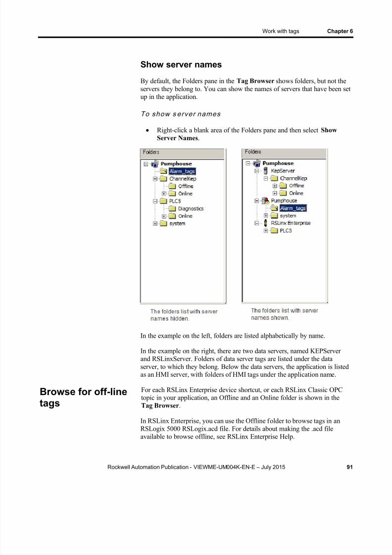
8/15/2019 Factory Talk View ME
http://slidepdf.com/reader/full/factory-talk-view-me 91/635
Work with tags Chapter 6
Rockwell Automation Publication - VIEWME-UM004K-EN-E – July 2015 91
Show server names
By default, the Folders pane in the Tag Browser shows folders, but not theservers they belong to. You can show the names of servers that have been setup in the application.
To show s erver names
Right-click a blank area of the Folders pane and then select ShowServer Names .
In the example on the left, folders are listed alphabetically by name.
In the example on the right, there are two data servers, named KEPServerand RSLinxServer. Folders of data server tags are listed under the dataserver, to which they belong. Below the data servers, the application is listedas an HMI server, with folders of HMI tags under the application name.
For each RSLinx Enterprise device shortcut, or each RSLinx Classic OPCtopic in your application, an Offline and an Online folder is shown in theTag Browser .
In RSLinx Enterprise, you can use the Offline folder to browse tags in anRSLogix 5000 RSLogix.acd file. For details about making the .acd fileavailable to browse offline, see RSLinx Enterprise Help.
Browse for off-linetags

8/15/2019 Factory Talk View ME
http://slidepdf.com/reader/full/factory-talk-view-me 92/635

8/15/2019 Factory Talk View ME
http://slidepdf.com/reader/full/factory-talk-view-me 93/635
Work with tags Chapter 6
Rockwell Automation Publication - VIEWME-UM004K-EN-E – July 2015 93
Assign tags
This example shows the Trigger dialog box that opens when you click theAdd button in the Triggers tab of the Alarm Setup editor:
To assign a tag, do one of the following:
In the Tag or expression column, type the tag name.
In the Tag column , click the Browse button and then select a tagfrom the Tag Browser .
For information about using the Tag Browser , see Help.
Assign tags to graphic objects
In the Graphics editor, you can assign tags to many of the graphic objectsyou create.
You can use up to 1,000 tags per graphic display. This limit includes the tagscontained in embedded variables and expressions. For example, if anexpression references the same tag twice, this counts as two tag references.
To assign tags to a graphic object, use one of these methods:
Double- click the object to open the object’s Properties dialog box, andthen click the Connections tab.

8/15/2019 Factory Talk View ME
http://slidepdf.com/reader/full/factory-talk-view-me 94/635
Chapter 6 Work with tags
94 Rockwell Automation Publication - VIEWME-UM004K-EN-E – July 2015
Select the object, and then assign tags in the Connections tab of theProperty Panel .
Use expressions to manipulate tag values
Many of the connections to which you can assign a tag also permit the use ofexpressions to perform logical or mathematical calculations on tag values. Ifyou assign an expression, FactoryTalk View monitors the expression valuerather than the original tag value. For example, your machine might sendvalues to the data source in the form of temperature in degrees Celsius. Youcould use an expression to convert the value to degrees Fahrenheit, and thenmonitor the expression result rather than the original tag value.
If you can assign an expression, a Browse button is present in the Exprncolumn in the Connections tab.
To assign an expression, do one of the following
In the Exprn column, click the Browse button, and then create anexpression in the Expression editor. Use this method if you want tocheck the expression syntax.

8/15/2019 Factory Talk View ME
http://slidepdf.com/reader/full/factory-talk-view-me 95/635
Work with tags Chapter 6
Rockwell Automation Publication - VIEWME-UM004K-EN-E – July 2015 95
In the Tag or expression column, type the expression. The expressionsyntax is not checked if you use this method.
For more information about expressions, see Use expressions on page 475 .
Substitute tag names used in graphic objects
You can use tag substitution or Find and Replace to replace tag names andexpressions assigned to the connections for graphic objects. For example, ifyou assign a tag to multiple objects in a graphic display, and then decide touse a different name for the tag, you can create a new tag and then use tagsubstitution or Find and Replace to search for all tag references with the oldname, and replace them with the new tag name.
You can also use tag substitution to replace the tags contained in embeddedvariables.
For more information about tag substitution and Find and Replace, seeReplace tags using tag substitution on page 368 .
Analog and digital tag values can be logged, including both HMI and dataserver tags. To set up data logging, use the Data Log Models editor. Formore information, see Set up data logging on page 519 .
A macro is a list of tag assignments stored in a text file. Whenever you runthe macro, the specified values are written to the tags. For more informationabout macros, see Use macros on page 561 .
Log tag values
Use macros toassign values totags

8/15/2019 Factory Talk View ME
http://slidepdf.com/reader/full/factory-talk-view-me 96/635
Chapter 6 Work with tags
96 Rockwell Automation Publication - VIEWME-UM004K-EN-E – July 2015
You can also use recipes to assign values to multiple tags with a button press.For information about using recipes to assign values to tags, see Set upRecipePlus on page 547 .

8/15/2019 Factory Talk View ME
http://slidepdf.com/reader/full/factory-talk-view-me 97/635
Rockwell Automation Publication - VIEWME-UM004K-EN-E – July 2015 97
Chapter 7
Use HMI tags
This chapter describes:
HMI tag types
Use the Tags editor
Data sources
Address syntax for device tags
Organize HMI tags
View tag statistics
Other methods for creating HMI tags
Import HMI tags
HMI tags are tags you create in FactoryTalk View. For information aboutwhen to use HMI tags versus when to use data server tags, see Work withtags on page 85 .
You can create and use these types of HMI tags in FactoryTalk View:
This tag type Stores this type of data
Analog Range of values.Use analog tags to represent variable states such astemperature or the position of rotary controls.
Digital 0 or 1.Use digital tags to represent devices that can only be on or off,such as switches, contacts, and relays.
String ASCII string, series of characters, or whole words (maximum of82 characters).Use string tags to represent devices that use text, such as abar code scanner that uses an alphanumeric product code.
System Information generated while the system is running, such as thename of the logged-in user, system time and date, and so on.FactoryTalk View creates system tags when you create anapplication. The system tags are stored in the folder called"system" in the HMI tag database. You cannot edit systemtags. You can use system tags anywhere you would use anyother type of tag. For a list of system tags, see System tags onpage 593 .
HMI tag types

8/15/2019 Factory Talk View ME
http://slidepdf.com/reader/full/factory-talk-view-me 98/635
Chapter 7 Use HMI tags
98 Rockwell Automation Publication - VIEWME-UM004K-EN-E – July 2015
Analog tags that use floating-point values
You can assign analog tags to most of the connections in FactoryTalk View,including both HMI and data server tags. If the analog tag uses afloating-point data type but an integer value is required, the floating-pointvalue is rounded.
For information about the data types available for analog tags, see Help.
How values are rounded
When a floating-point value must be rounded to an integer, this is how thevalue is rounded:
If the number after the decimal is 4 or less, the value is rounded down.For example, 8.495 is rounded to 8.
If the number after the decimal is 6 or more, the value is rounded up.For example, 8.6 is rounded to 9.
If the number after the decimal is 5, the value is rounded using a"banker’s algorithm," to average out the rounding over time:
If the number before the decimal is 0, the value is rounded down.For example, 10.5 is rounded to 10.
If the number before the decimal is an odd number, the value isrounded up. For example, 11.5 is rounded to 12.
If the number before the decimal is an even number, the value isrounded down. For example, 12.5 is rounded to 12.
Floating point values are rounded to a maximum of six digits.Therefore, using a floating-point data type and adding to it a valuethat exceeds the six significant digits will result in a roundingerror. For example, adding any number to 999,999 will result in arounding error.
This rounding method is also used for Numeric Input Enable buttons that usethe implicit decimal position, if an integer tag is assigned to the button’sValue connection. For more information about the Numeric Input Enable
button, see Set up Numeric Input Enable buttons on page 418 .
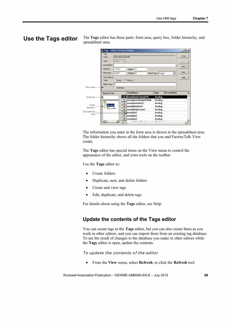
8/15/2019 Factory Talk View ME
http://slidepdf.com/reader/full/factory-talk-view-me 99/635
Use HMI tags Chapter 7
Rockwell Automation Publication - VIEWME-UM004K-EN-E – July 2015 99
The Tags editor has these parts: form area, query box, folder hierarchy, andspreadsheet area.
The information you enter in the form area is shown in the spreadsheet area.The folder hierarchy shows all the folders that you and FactoryTalk Viewcreate.
The Tags editor has special items on the View menu to control theappearance of the editor, and extra tools on the toolbar.
Use the Tags editor to:
Create folders
Duplicate, nest, and delete folders
Create and view tags
Edit, duplicate, and delete tags
For details about using the Tags editor, see Help.
Update the contents of the Tags editor
You can create tags in the Tags editor, but you can also create them as youwork in other editors, and you can import them from an existing tag database.To see the result of changes to the database you make in other editors whilethe Tags editor is open, update the contents.
To update the contents o f the edi tor
From the View menu, select Refresh , or click the Refresh tool.
Use the Tags editor
8/15/2019 Factory Talk View ME
http://slidepdf.com/reader/full/factory-talk-view-me 100/635
Chapter 7 Use HMI tags
100 Rockwell Automation Publication - VIEWME-UM004K-EN-E – July 2015
When you select Refresh , the undo buffer is cleared and recentchanges can’t be automatically reversed.
Refresh is not available if you haven’t accepted the current tag.
For information about creating tags in other editors, see Other methods forcreating HMI tags on page 105 .
Search for HMI tags
Use the Tags editor’s query box to select the tags you want to show in thespreadsheet. This allows you to edit tags in different folders without
browsing the folder hierarchy. You can:
Select a single tag by typing the tag name.
Select multiple tags by typing wildcard characters.
These are the wildcard characters:
This character Does this
? Matches any single character.
* Matches any number of characters, including the backslash (\)character.Use this wildcard character by itself to show all the tags in theHMI tag database.
For example, to search for all the tags that contain the string "pump" in theirname, type *pump* in the Search For box. When you press Enter , a list oftags containing the string "pump" appears in the spreadsheet.
When you do searches, remember that the backslash in a folder name countsas a character in the tag name.
You can also use Find to search for every occurrence of a specific tag or textstring throughout different components within FactoryTalk View MEapplications. Find also locates all the text strings within each component thatrefer to the tag.
To f ind a tag or text s t r ing
1. From the tool bar, click , or from the Tools menu, select Find .
2. Type the text string in Find what, or identify the tag to search for:

8/15/2019 Factory Talk View ME
http://slidepdf.com/reader/full/factory-talk-view-me 101/635

8/15/2019 Factory Talk View ME
http://slidepdf.com/reader/full/factory-talk-view-me 102/635
Chapter 7 Use HMI tags
102 Rockwell Automation Publication - VIEWME-UM004K-EN-E – July 2015
Click the browse button next to Find within .
From the Find within dialog box, select the product componenttypes to be searched then click OK to save the selection and close
the dialog box.4. Click Search to show all the found items in a spreadsheet form. 4.
5. You can double click any of the found items to open it with theappropriate editor.
When creating an HMI tag, you must specify a data source. The data sourcedetermines whether the tag receives its values externally or internally.
The data source
The FactoryTalk View documentation uses the term data source as a genericterm that includes all possible sources of tag data, for both data server tagsand HMI tags. The data source can be memory or a device such as a
programmable controller or an OPC server. FactoryTalk View writes valuesto and reads values from the data source. The data source is set up toexchange information (in the form of numeric or string values) between theFactoryTalk View value table and the machine that your application iscontrolling.
Device
A tag with device as its data source receives its data from a source external toFactoryTalk View. The data can come from a programmable controller orother device via RSLinx Enterprise, or from another OPC server. You canuse up to 5,000 device tags.
For analog tags with Device as the data source, the data type determines theformat used when reading and writing tag data to the data server.
Do not create HMI Tags that are pointing to a System Tag. When a projectcontains an HMI tag pointing to a System Tag, users may fail in creating anMER or have runtime performance issues.
Memory
A tag with memory as its data source receives its data from (and storesvalues in) the FactoryTalk View internal value table. Tags with memory asthe data source do not count toward the total tag limit.
Data sources

8/15/2019 Factory Talk View ME
http://slidepdf.com/reader/full/factory-talk-view-me 103/635
Use HMI tags Chapter 7
Rockwell Automation Publication - VIEWME-UM004K-EN-E – July 2015 103
For analog tags with Memory as the data source, select the data type thatmatches the format of the data you will store in the tag. Choosing Default isthe same as choosing Floating Point .
For device tags, you must provide the address and path to the OPC serverthat is connected to the data source. For example, the OPC server could beconnected to a device such as a programmable controller.
The syntax for OPC tag addresses is:
[AccessPath]Address
or
::[AccessPath]Address
where :: indicates that the address resides in a data server in the application.(The two colons are necessary when the address contains a colon, forexample, N7:0.)
The square brackets are part of the syntax. They do not indicate optional parameters.
The access path is one of the following:
For communications with an RSLinx Enterprise data server, the access path is the name of the device shortcut in RSLinx Enterprise.
For communications with an RSLinx Classic OPC server, the access
path is the name of an OPC topic in RSLinx Classic. For communications with other OPC servers, the access path might be
optional. For information about the syntax for the access path, see yourOPC server documentation.
Example: Logix5000 addressing
We recommend that you use the Tag Browser or Find and Replace to selectOPC items. When you use the Tag Browser the correct syntax and datatypes are selected automatically.
However, if you want to define tags before setting up communications, youcan type the address manually, as shown in this example. If you type theaddress manually, be sure to select the data type for the tag that matches thedata type used by the Logix5000 processor. If you use the Default data type,values are treated as floating-point values.
This example shows you how to specify the OPC topic, item name, and bitlevel of an item that uses the integer data type in a Logix5000 processor.
Address syntax fordevice tags
8/15/2019 Factory Talk View ME
http://slidepdf.com/reader/full/factory-talk-view-me 104/635
Chapter 7 Use HMI tags
104 Rockwell Automation Publication - VIEWME-UM004K-EN-E – July 2015
OPC topic and item addressing
Logix5000 uses this addressing syntax:
[ Device shortcut ]item name for RSLinx Enterprise.
[OPC topic name ]item name for RSLinx Classic.
In this example, the RSLinx Enterprise device shortcut name for theLogix5000 processor is CLGX. To connect to an OPC item called Motor,type this address:
[CLGX]Motor
Bit level addressing
You can gain access to the bit level of an item that uses the integer data type by appending .# to the end of the tag address, where # is the number of the bit you want access to.
For example, to gain access to the first bit of the integer item Motor, type thisaddress:
[CLGX]Motor.0
Organize tags makes finding and using tags faster and simpler. To organizeyour tags, try these tips:
Establish naming conventions.
Naming conventions enable you to use wildcard characters mosteffectively when searching for and showing tags during development.
Use folders to group related tags.
Name tags
Tag names can be up to 255 characters long including folder name. If youcreate a folder, the folder name becomes part of the tag name. The backslash(\) after a folder name counts as a character.
The tag name can contain these characters:
A to Z
0 to 9
underscore (_) and dash (-)
Tag names cannot contain spaces. The tag name can be mixed case. Tagnames preserve upper and lower case for readability but are not case
Organize HMI tags

8/15/2019 Factory Talk View ME
http://slidepdf.com/reader/full/factory-talk-view-me 105/635
Use HMI tags Chapter 7
Rockwell Automation Publication - VIEWME-UM004K-EN-E – July 2015 105
sensitive. For example, the tag name MixerValve1 is the same asmixervalve1.
When a tag name starts with a number or contains a dash, enclose the name
in curly brackets { } when you use it in an expression, for example,{N33-0}. For more information about using tags in expressions, see Useexpressions on page 475 .
Use folders to group tags
To organize tags, create a folder to store tags that are related to one another.To separate the folder name from the rest of the tag name, use a backslash (\).For example, tags in the folder called Pump would start with Pump\.
For greater organization, you can nest folders. For example, you can organizethe HMI tag database first by area, then by machines in the area, and finally
by devices in each machine. The result might be Area1\Machine1\Pump.
To create similar groups of tags quickly, create one folder with its tags andthen duplicate the folder.
The Tag Statistics dialog box provides a summary of how many tags yourapplication uses, as well as other tag information such as the date the HMItag database was last modified. To view tag statistics, the Tags editor must
be open and have focus.
To view tag statistics
From the View menu, select Tag Statistics .
In addition to creating tags in the Tags editor, you can:
View tag statistics
Other methods forcreating HMI tags
8/15/2019 Factory Talk View ME
http://slidepdf.com/reader/full/factory-talk-view-me 106/635
Chapter 7 Use HMI tags
106 Rockwell Automation Publication - VIEWME-UM004K-EN-E – July 2015
Create tags as needed in other editors (using the Tag Browser ).
Import tags from a PLC or SLC database. For details see Import tagsfrom a PLC database on page 107 .
Create tags as needed in other FactoryTalk Vieweditors
You can create tags as needed in any editor or dialog box that uses tags. Youcan add a tag to the database by doing one of the following:
Click the Browse button in the Tag column to open the TagBrowser and create the tag. For information about using the TagBrowser , see Browse for tags on page 89 .
Type a new tag name in the Tag or expression column. Keep track ofthe tag name, and add the tag in the Tags editor when convenient.
Create tags as needed in the Data Log Modelseditor
In the Data Log Models editor, in the Tags in Model tab, you can add a tagto the database by doing one of the following:
Click the Browse button beside the Tags to add box to open theTag Browser and create the tag. For information about using the TagBrowser , see Browse for tags on page 89 .
Type a new tag name in the Tags to add box, and then click Add . Youare warned that the tag does not exist. Click Yes to add the tag to thelist of tags in the datalog model. Keep track of the tag name, and addthe tag in the Tags editor when convenient.

8/15/2019 Factory Talk View ME
http://slidepdf.com/reader/full/factory-talk-view-me 107/635
Use HMI tags Chapter 7
Rockwell Automation Publication - VIEWME-UM004K-EN-E – July 2015 107
For more information about the Data Log Models editor, see Set up datalogging on page 519 .
Use the Import PLC Tags dialog box to selectively import tags from a PLCor other database into your application’s HMI tag database. Tags imported inthis way are copied into the database. They are not shared with the sourcedatabase. This means changes to tags in your application do not affect thedatabase from which they have been imported, and vice versa.
You can import tags from any of these databases:
RSLogix 500 internal database, with file extension .rss
RSLogix 5 internal database, with file extension .rsp
RSLogix 5 or RSLogix 500, saved as an external database, with fileextension .ctd (before importing, explicitly export to the .ctd format to
be sure of including the latest changes)
For PLC and SLC addresses, the Import PLC Tags dialog box shows onlyaddresses that are used in the symbol or address list of the PLC programming
software.
To open the Import PLC Tags dialog box, do one ofthe following
In the Tag Browser , right-click the right pane, and then select ImportPLC Tags . For information about using the Tag Browser , see Browsefor tags on page 89 .
Import tags from aPLC database

8/15/2019 Factory Talk View ME
http://slidepdf.com/reader/full/factory-talk-view-me 108/635
Chapter 7 Use HMI tags
108 Rockwell Automation Publication - VIEWME-UM004K-EN-E – July 2015
In the Tags editor, from the Edit menu select Other Databases , or
click the DB Browser tool .
For more information about using the Import PLC Tags dialog box, seeHelp.
You can also import PLC or SLC databases into FactoryTalk View using theTag Import and Export Wizard.
You can use the wizard to:
Export your application’s tags to a .csv file.
Import tags from another FactoryTalk View application’s tag .csv file.
Merge tags from another FactoryTalk View application (that is, importthem directly from the application, without first creating a tag .csvfile).
Import tags from RSLogix 5 or RSLogix 500, saved as an externaldatabase, with file extension .ctd (before importing, explicitly export to
the .ctd format to be sure of including the latest changes).
To start the wizard, do one of the following
In FactoryTalk View Studio, from the Tools menu, select Tag Importand Export Wizard .
Use the Tag Import
and Export Wizard

8/15/2019 Factory Talk View ME
http://slidepdf.com/reader/full/factory-talk-view-me 109/635
Use HMI tags Chapter 7
Rockwell Automation Publication - VIEWME-UM004K-EN-E – July 2015 109
From the Windows Start menu, select Programs> RockwellSoftware> FactoryTalk View> Tools> Tag Import and ExportWizard .
For details about using the wizard, see t he wizard’s Help.

8/15/2019 Factory Talk View ME
http://slidepdf.com/reader/full/factory-talk-view-me 110/635
Chapter 7 Use HMI tags
110 Rockwell Automation Publication - VIEWME-UM004K-EN-E – July 2015

8/15/2019 Factory Talk View ME
http://slidepdf.com/reader/full/factory-talk-view-me 111/635
Rockwell Automation Publication - VIEWME-UM004K-EN-E – July 2015 111
Chapter 8
Set up global connections
This chapter describes:
What global connections are
Update the date and time
Change displays
Control display changes remotely
Use parameter files or parameter lists with display changes
Close On Top displays
Print displays
Run macros
Set up the backlight intensity remotely
Monitor runtime RAM usage
Global connections are connections that apply to your entire runtimeapplication. Global connections allow the data source to control or interactwith your application at run time.
You can use global connections to:
Update the date and time at the data source using the runtimeterminal’s date a nd time.
Update the date and time on the runtime terminal using the data sourcedate and time.
Notify the data source of the current display number.
Notify the data source when a display is printed.
Change the display on the runtime terminal remotely (from the datasource).
Close On Top displays
Apply parameter files or parameter lists to the tag placeholders in thechanged displays.
Print the current display from the data source.
Run up to five macros from the data source, when a tag or expressionresult changes.
About globalconnections
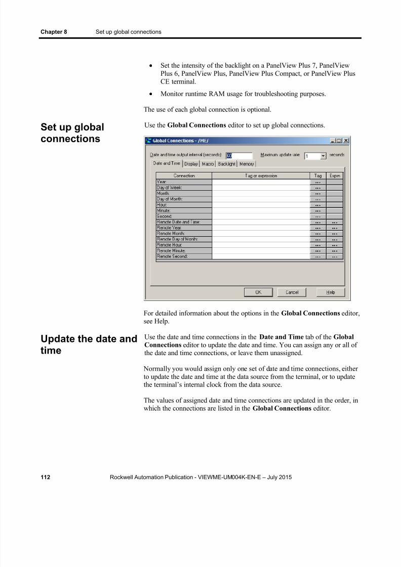
8/15/2019 Factory Talk View ME
http://slidepdf.com/reader/full/factory-talk-view-me 112/635
Chapter 8 Set up global connections
112 Rockwell Automation Publication - VIEWME-UM004K-EN-E – July 2015
Set the intensity of the backlight on a PanelView Plus 7, PanelViewPlus 6, PanelView Plus, PanelView Plus Compact, or PanelView PlusCE terminal.
Monitor runtime RAM usage for troubleshooting purposes.The use of each global connection is optional.
Use the Global Connections editor to set up global connections.
For detailed information about the options in the Global Connections editor,see Help.
Use the date and time connections in the Date and Time tab of the GlobalConnections editor to update the date and time. You can assign any or all ofthe date and time connections, or leave them unassigned.
Normally you would assign only one set of date and time connections, eitherto update the date and time at the data source from the terminal, or to update
the terminal’s internal clock from the data source. The values of assigned date and time connections are updated in the order, inwhich the connections are listed in the Global Connections editor.
Set up globalconnections
Update the date andtime

8/15/2019 Factory Talk View ME
http://slidepdf.com/reader/full/factory-talk-view-me 113/635

8/15/2019 Factory Talk View ME
http://slidepdf.com/reader/full/factory-talk-view-me 114/635
Chapter 8 Set up global connections
114 Rockwell Automation Publication - VIEWME-UM004K-EN-E – July 2015
The date and time are updated at the rate specified in the Maximum updaterate box, but changes are not made until the Remote Date and Timeconnection changes to a new non-zero value.
Use these global connections in the Display tab of the Global Connections editor to monitor and control display changes:
Replace Display Number — notifies the data source of the number ofthe Replace display that’s currently open.
Remote Display Number — allows the data source to change thedisplay on the runtime computer.
Control display changes remotely
To control display changes remotely, you can set up the data source to opengraphic displays using global connections.
Global connections are connections that apply to your entire runtimeapplication. Global connections allow the data source to control or interactwith your application at run time.
For example, the Remote Display Number connection is a globalconnection that you can use to control display changes from the data source.You can also use global connections to apply parameters to the displays thatare opened from the data source, to close one or more On Top displays fromthe data source, to print graphic displays from the data source, to run macros
from the data source, to control the date and time displayed on the runtimeterminal, to set the intensity of PanelView backlights, and to monitor runtimeRAM usage. For more information about global connections, see Set upglobal connections on page 111 .
Remote display changes and security
If you set up the data source to open graphic displays remotely, remotedisplay changes occur whether or not the logged-in user has security accessto a given display.
Set up remote display changes
This section outlines the steps for setting up remote display changes. Formore detailed information about the Global Connections editor, see Help.
Change displays
8/15/2019 Factory Talk View ME
http://slidepdf.com/reader/full/factory-talk-view-me 115/635
Set up global connections Chapter 8
Rockwell Automation Publication - VIEWME-UM004K-EN-E – July 2015 115
To se t up remote d isplay changes
1. In the Graphics editor, in the Display Settings dialog box, every newdisplay is assigned the number 1 by default. Therefore, to use remotedisplay changes, you must assign a unique display number to eachReplace and On Top display that you want to change remotely.
For more information about graphic displays, see Use graphic displays on page 299 .
2. In the Global Connections editor, assign a tag or an expression to theRemote Display Number connection.
3. If you assign a tag to the Remote Display Number connection, set upthe data source to send a display’s number to the connection when youwant the display to open.
4. If you assign an expression to the Remote Display Number connection, FactoryTalk View monitors the values of the tags used inthe expression, and uses the expression result to determine whichdisplay to open.
5. If you assign a tag to the Close An On Top Display or Close all OnTopDisplays connection, or both, set up the data source to send adisplay’s number to the connection when you want one or moredisplays to close.
6. If you assign an expression to the Close An On Top Display or Closeall On Top Displays connections, FactoryTalk View monitors thevalues of the tags used in the expression, and uses the expression resultto determine which display to close.
Use these global connections in the Display tab of the Global Connections editor to monitor and control display printing:
Display Print Active — notifies the data source that a display print isin progress.
Remote Display Print — allows the data source to trigger a display print.
The operator can also print the current display by pressing the display print button. For information about setting up this button, see Help.
When the data source or the operator prints a display, everything on thescreen is printed, including the current display, pop-up windows, and anyvisible background applications.
If you plan to print graphic displays remotely, turn off the screen saver. If thescreen saver is on when a remote display print is triggered, only the screensaver image is printed.
Print displays
8/15/2019 Factory Talk View ME
http://slidepdf.com/reader/full/factory-talk-view-me 116/635
Chapter 8 Set up global connections
116 Rockwell Automation Publication - VIEWME-UM004K-EN-E – July 2015
For information abut turning off the screen saver on personal computers, seeyour Windows documentation.
For information about turning off the screen saver on a PanelView Plus 7,
PanelView Plus 6, PanelView Plus, PanelView Plus Compact, or PanelViewPlus CE terminal, see the PanelView Plus Terminals User Manual.
Use these global connections to close displays remotely:
Close an On Top display — notifies the data source of the number ofthe On Top display to be closed.
Close All On Top Displays — notifies the application to close all OnTop displays whose display number is not zero.
Only replaceable On Top displays can be closed remotely.
Use these global connections to replace tag placeholders in displays that use parameters when they open:
Parameter file — identifies the parameter file for the display beingopened remotely.
Use Parameter List — notifies the application that a parameter list isto be used to provide the parameters to the display being openedremotely.
Parameter Tag #1-10 — the tag values assigned to these globalconnections will replace the tag placeholders in the display beingopened remotely.
Use these global connections in the Macro tab of the Global Connectionseditor to run macros:
This connection Runs this macro
Remote Macro1 Macro1
Remote Macro2 Macro2
Remote Macro3 Macro3
Remote Macro4 Macro4
Remote Macro5 Macro5
Create the macros in the Macros editor. Make sure you name them exactlyas shown in the right column of the preceding table (with no space in thename).
When the tag or expression assigned to one of these connections changes to anew non-zero value, FactoryTalk View runs the associated macro.
Leave time for a macro to run before starting a new macro. Otherwise,FactoryTalk View will queue the macros, which consumes memory and
Close On Topdisplays
Apply parameters tochanged displays
Run macros
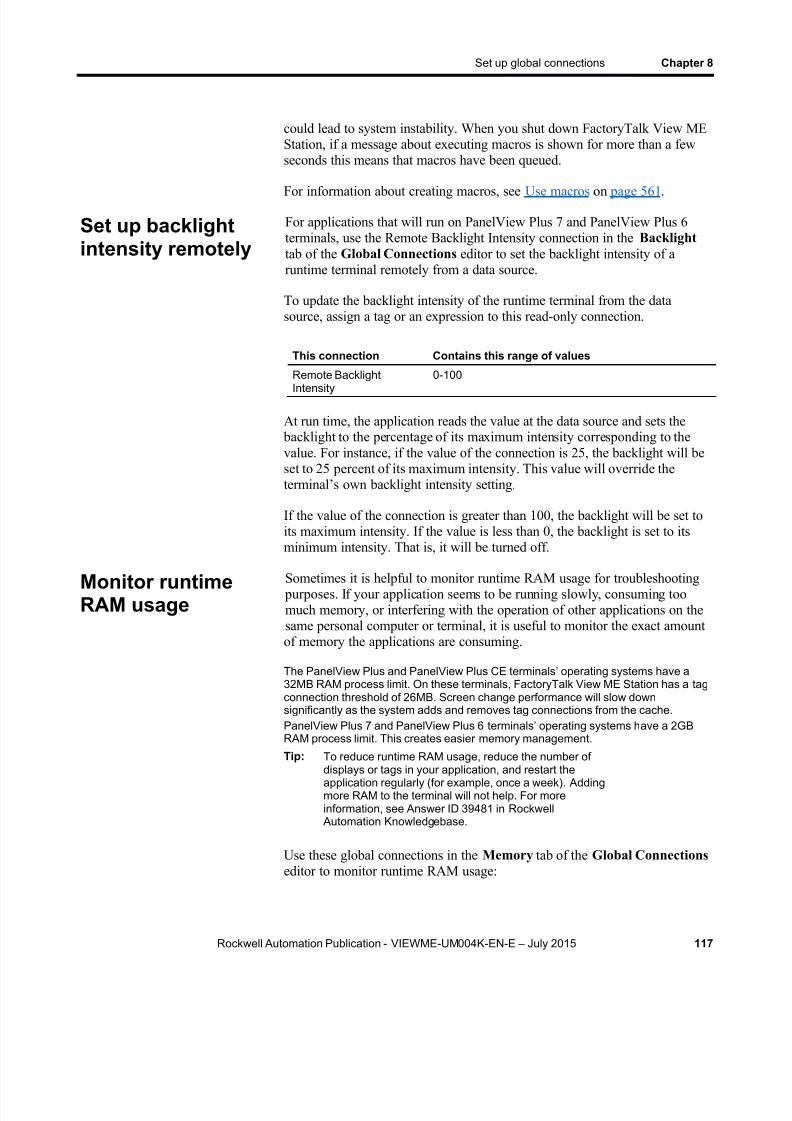
8/15/2019 Factory Talk View ME
http://slidepdf.com/reader/full/factory-talk-view-me 117/635
Set up global connections Chapter 8
Rockwell Automation Publication - VIEWME-UM004K-EN-E – July 2015 117
could lead to system instability. When you shut down FactoryTalk View MEStation, if a message about executing macros is shown for more than a fewseconds this means that macros have been queued.
For information about creating macros, see Use macros on page 561 .
For applications that will run on PanelView Plus 7 and PanelView Plus 6terminals, use the Remote Backlight Intensity connection in the Backlight tab of the Global Connections editor to set the backlight intensity of aruntime terminal remotely from a data source.
To update the backlight intensity of the runtime terminal from the datasource, assign a tag or an expression to this read-only connection.
This connection Contains this range of values
Remote BacklightIntensity
0-100
At run time, the application reads the value at the data source and sets the backlight to the percentage of its maximum intensity corresponding to thevalue. For instance, if the value of the connection is 25, the backlight will beset to 25 percent of its maximum intensity. This value will override theterminal’s own backlight intensity setting.
If the value of the connection is greater than 100, the backlight will be set toits maximum intensity. If the value is less than 0, the backlight is set to itsminimum intensity. That is, it will be turned off.
Sometimes it is helpful to monitor runtime RAM usage for troubleshooting purposes. If your application seems to be running slowly, consuming toomuch memory, or interfering with the operation of other applications on thesame personal computer or terminal, it is useful to monitor the exact amountof memory the applications are consuming.
The PanelView Plus and PanelView Plus CE terminals’ operating systems have a32MB RAM process limit. On these terminals, FactoryTalk View ME Station has a tagconnection threshold of 26MB. Screen change performance will slow downsignificantly as the system adds and removes tag connections from the cache.PanelView Plus 7 and PanelView Plus 6 terminals’ operating systems h ave a 2GBRAM process limit. This creates easier memory management.
Tip: To reduce runtime RAM usage, reduce the number ofdisplays or tags in your application, and restart theapplication regularly (for example, once a week). Addingmore RAM to the terminal will not help. For moreinformation, see Answer ID 39481 in Rockwell
Automation Knowledgebase.
Use these global connections in the Memory tab of the Global Connections editor to monitor runtime RAM usage:
Set up backlightintensity remotely
Monitor runtimeRAM usage

8/15/2019 Factory Talk View ME
http://slidepdf.com/reader/full/factory-talk-view-me 118/635
Chapter 8 Set up global connections
118 Rockwell Automation Publication - VIEWME-UM004K-EN-E – July 2015
This connection Provides this information, in kilobytes (Kb)
ME Runtime RAM Usage The amount of memory being used by your application(and by the MERuntime.exe process)
Total RAM Usage The total amount of memory being used by allapplications (and processes) on the personal computeror terminal
Available RAM The remaining amount of memory available
Remote RAM Usage Assign a tag or expression to this connection. When ithas a non-zero value, data is sent to the other threeconnections, if assigned.
You can monitor the values of the MERuntime RAM Usage , Total RAMUsage , and Available RAM connections using data logging or using graphicobjects such as numeric displays. The connections are updated every tenseconds as long as the Remote RAM Usage connection has a non-zero
value. Set up the data source to set this connection to a non-zero value whenyou want memory monitoring to occur, or assign the same tag or expressionto a graphic object such as a Maintained push button that the operator canuse to turn memory monitoring on and off.
These connections are available when you run FactoryTalk View ME Stationon a personal computer and on the PanelView Plus 7, PanelView Plus 6,PanelView Plus, PanelView Plus Compact, and PanelView Plus CEterminals.
For PanelView Plus 7, PanelView Plus 6, PanelView Plus, PanelView PlusCompact, and PanelView Plus CE terminals, you can also turn on the display
of RAM usage statistics at run time. To do this, in the Configuration Mode window, select Runtime RAM Usage , and then make your selections in theRuntime RAM Usage window. For more information, see the PanelView
Plus Terminals User Manual .

8/15/2019 Factory Talk View ME
http://slidepdf.com/reader/full/factory-talk-view-me 119/635
Rockwell Automation Publication - VIEWME-UM004K-EN-E – July 2015 119
Chapter 9
Set up alarms
This chapter describes:
Steps for setting up alarms
Prepare to set up alarms
How alarms work
Alarm trigger data types
Tips for using array tags
Optional alarm connections.
Create alarm messages in multiple languages
The [ALARM], [ALARM BANNER], [ALARM MULTI-LINE],[STATUS], and [HISTORY] displays
Use displays from the library in your application
Create your own alarm display
Open and close the alarm display
How the alarm list, alarm banner, and alarm status list graphic objectswork
Use buttons to acknowledge, silence, clear, and delete alarms
Use buttons to sort alarms and reset alarm status
An alarm occurs when something goes wrong or is about to go wrong.Alarms can signal that a device or process has ceased operating withinacceptable, predefined limits, and can indicate breakdown, wear, or processmalfunctions. Alarms are also used to indicate the approach of a dangerouscondition.
Alarms are an important part of most plant control applications because anoperator must know the instant something goes wrong. It is often equallyimportant to have a record of the alarm and whether the alarm wasacknowledged.
PanelView Plus 7 Standard applications, and Compact Machine Editionapplications (applications running on PanelView Plus 6 Compact, orPanelView Plus Compact terminals) have a limit of 200 alarm messages.
About alarms

8/15/2019 Factory Talk View ME
http://slidepdf.com/reader/full/factory-talk-view-me 120/635
Chapter 9 Set up alarms
120 Rockwell Automation Publication - VIEWME-UM004K-EN-E – July 2015
Multiple language alarm messages
A key component of any alarm system is the messages that appear whenalarms occur. FactoryTalk View supports alarm messages in multiplelanguages. For information about setting up alarm messages in multiplelanguages, see Create alarm messages in multiple languages on page 135 .
Other multiple language alarm features
FactoryTalk View supports using multiple languages for all captions onalarm objects. In addition, these alarm features can be translated into multiplelanguages:
Title of the alarm history report
Title of the alarm status report
Alarm objects and reports use the time formats for the current applicationlanguage. For more information about using multiple languages, see Set uplanguage switching on page 197 .
Follow these steps to set up alarms:
1. In the Alarm Setup editor, set up alarm triggers (the tags orexpressions to monitor), define the alarm messages and their triggervalues, and specify the graphic display to open when alarms occur (ifany).
Also use this editor to specify trigger types, Acknowledge all values,the maximum alarm log file size, the time settings (hold time andupdate rates), and optional connections.
2. In the Startup editor, ensure that the Alarms box is selected (it isselected by default). See Help.
Steps for setting upalarms

8/15/2019 Factory Talk View ME
http://slidepdf.com/reader/full/factory-talk-view-me 121/635
Set up alarms Chapter 9
Rockwell Automation Publication - VIEWME-UM004K-EN-E – July 2015 121
3. If desired, in the Graphics editor, modify the default [ALARM]display, or create your own graphic display to use for alarms. Forexample, if you won’t be using audible alarm signals, edit the defaultdisplay to remove the silence alarms button.
For information about graphic displays, see Use graphic displays on page 299 .
4. Test alarms on the runtime system.
As your application is running, information is continually sent to the datasource about the state of the various processes. For example, yourapplication might be monitoring whether a valve is open or closed, or thetemperature in a boiler. Values representing the status of these processes aresent to the data source.
The first step in setting up alarms is determining which processes to monitorfor alarm conditions.
The data source
The FactoryTalk View documentation uses the term data source as a genericterm that includes all possible sources of tag data, for both data server tagsand HMI tags. The data source can be memory or a device such as a
programmable controller or an OPC server. FactoryTalk View writes valuesto and reads values from the data source. The data source is set up toexchange information (in the form of numeric or string values) betweenFactoryTalk View and the machine that your application is controlling.
Tags and expressions
Before setting up alarms, you must set up data server or HMI tagscorresponding to the addresses at the data source that will store the valuesyou want to monitor for alarm conditions. You can monitor analog anddigital tags for alarm conditions, including both HMI and data server tags.You cannot monitor string tags.
For information about setting up data server tags, see your OPC data serverdocumentation. For information about creating HMI tags, see Use HMI tags on page 97 .
You can also use expressions to perform logical or mathematical calculationson tag values, and then monitor the expression value rather than the originaltag value. For example, you could use an expression to monitor whether a tagvalue has increased or decreased beyond a threshold value: If Tag1 > 90 then1 else 2.
Prepare to set upalarms

8/15/2019 Factory Talk View ME
http://slidepdf.com/reader/full/factory-talk-view-me 122/635
Chapter 9 Set up alarms
122 Rockwell Automation Publication - VIEWME-UM004K-EN-E – July 2015
For information about creating expressions, see Use expressions on page475 .
Identify alarm conditions
Once you have identified the processes you want to monitor for alarms, andthe tags or expressions that will store the values representing the status of the
processes, you must determine the acceptable range of values for each tag orexpression. Then you can set up alarms to notify the operator when a value isoutside the normal operating range.
Import and export alarm setup files
The Alarm Import Export Wizard in FactoryTalk View Studio allows you toexport alarm information to an XML file, and to import an alarm setup XMLfile.
For example, you can export an application’s alarm setup information,import the setup to another FactoryTalk View application, and then modify itin the new application to suit your requirements. Or, you can modify the file
before importing it into the new application.
You can use the Alarm Import Export Wizard to import alarm setupinformation that has been created using an external programming tool oreditor, or you can import a FactoryTalk View XML file.
For more information about importing and exporting alarm setup files, seeImport and export alarm XML files on page 597 .
This section provides an overview of the key components of yourapplication’s alarm system, and describes how the d ifferent parts worktogether.
Alarm triggers and trigger values
You specify the tags and expressions (also known as connections) to monitor
for alarm conditions by creating an alarm trigger for each connection.
Each alarm trigger can generate one or more alarm messages, associated withdifferent trigger connection values. For each alarm trigger, you specify thetrigger values that will generate alarm messages, and create the messages toshow for the trigger values.
The trigger value can be a non-zero integer value or a bit position, dependingon which trigger data type you assign. For more information about triggerdata types, see Alarm trigger data type on page 129 .
How alarms work
8/15/2019 Factory Talk View ME
http://slidepdf.com/reader/full/factory-talk-view-me 123/635
Set up alarms Chapter 9
Rockwell Automation Publication - VIEWME-UM004K-EN-E – July 2015 123
An alarm’s Trigger and Remote Ack settings should not be configured touse the same tag. Doing so may cause unpredictable alarm acknowledgement
behaviors.
Filter alarm triggers in multiple languages
FactoryTalk View 5.00 and later supports alarm triggers in multiplelanguages. When you create an alarm trigger, its name is in the currentapplication language. You can export alarm triggers for translation and thenimport them back into the application. For details, see Set up languageswitching on page 197 .
Various graphic objects allow you to specify the alarm triggers, to which theobject’s action applies, using the name of the alarm trigger. This is calledfiltering alarms. When you translate trigger names into other languages, thedefault language is used to show the trigger name in the object ’s selectionlist. These graphic objects allow you to specify alarm triggers using aselection list called the Trigger Label Selector:
Alarm list
Alarm status list
Alarm banner
Clear alarm history button
Acknowledge all alarms button
Print alarm history button Print alarm status button
If the trigger label name has not been set up in the default language, theTrigger Label Selector shows a question mark (?) instead of the trigger labelname. To correct the display, you must import the trigger labels for thedefault language.
You can also manually type in the trigger label names to use to filter alarms.If you manually type in the trigger names, specify the names in the defaultlanguage.
If you change the default language, you must re-specify the trigger labels foreach of the graphic objects listed above, using the trigger label names in thenew default language. For more information about the default language, seeThe default language on page 198 .

8/15/2019 Factory Talk View ME
http://slidepdf.com/reader/full/factory-talk-view-me 124/635
Chapter 9 Set up alarms
124 Rockwell Automation Publication - VIEWME-UM004K-EN-E – July 2015
Alarm notification methods
You can use any combination of these methods to notify the operator that analarm condition has occurred:
Open an alarm graphic display containing an appropriate alarmmessage.
Set off an audible signal (if the application is running on a personalcomputer).
Send a message to a printer.
Send a message to the data source.
If you set up alarm messages in multiple languages, make sure that the datasource can either receive the message in Unicode format or convert it into
ASCII characters for all the languages you will be using.
To use these methods, select the Display , Audio , Print , and Message to Tag options when you create your messages.
If you need to keep a permanent record of alarms, be sure to select the Printoption. You can also print the contents of the alarm log file periodically, asdescribed on Methods for printing alarm information on page 128 . (Thealarm log file is also referred to as the alarm history.)
Show alarm information
FactoryTalk View comes with these alarm displays:
[ALARM], in the Displays folder, contains an alarm banner graphicobject that is set up to show the newest active alarm in the alarm logfile.
[ALARM BANNER], a display in the Libraries folder, contains analarm banner graphic object that is set up to show the newest activealarm in the alarm log file.
[ALARM MULTI-LINE], a display in the Libraries folder, contains analarm list graphic object that is set up to show all the alarms in the
alarm log file: active, inactive, acknowledged, and unacknowledged. [STATUS], a display in the Libraries folder, contains an alarm status
list graphic object that is set up to show active alarms. It contains aGoto display button for opening the [HISTORY] display. This displayis available in two sizes.
[HISTORY], a display in the Libraries folder, contains an alarm listgraphic object and a Goto display button for opening the [STATUS]display. The alarm list is set up to show all the alarms in the alarm log

8/15/2019 Factory Talk View ME
http://slidepdf.com/reader/full/factory-talk-view-me 125/635
Set up alarms Chapter 9
Rockwell Automation Publication - VIEWME-UM004K-EN-E – July 2015 125
file: active, inactive, acknowledged, and unacknowledged. This displayis available in two sizes.
By default, the [ALARM] graphic display opens automatically at run time
when an alarm is generated.
You can accept the default, edit the [ALARM] display, use one of the otheralarm displays, or create your own display. If you select not to automaticallyopen a graphic display for alarm notification, an alternative is to provide theoperator with a way to open an alarm display when desired.
For more information, see:
The [ALARM] display on page 144
The [ALARM BANNER] display on page 145
The [ALARM MULTI-LINE] display on page 146 The [STATUS] display on page 147
The [HISTORY] display on page 148
Create your own alarm display on page 149
The alarm list graphic object on page 150
The alarm banner graphic object on page 152
The alarm status list graphic object on page 153
Interact with alarms
Depending on which alarm objects you set up, the operator can:
Acknowledge one or all alarms, or the alarms for a specific alarmtrigger
Clear and delete alarms
Silence alarms (if the application is running on a personal computer)
Sort alarms
Reset the status of all alarms
Print alarms
For information about the alarm button graphic objects the operator can useto work with alarms, see Use buttons with the alarm history and alarmobjects on page 154 .
8/15/2019 Factory Talk View ME
http://slidepdf.com/reader/full/factory-talk-view-me 126/635
Chapter 9 Set up alarms
126 Rockwell Automation Publication - VIEWME-UM004K-EN-E – July 2015
Use the da ta source to in terac t wi th a larms
You can also set up remote acknowledgement, silencing, and resetting ofalarms, to allow the data source to perform these functions. And you can setup the data source to determine which types of alarms to show (active,inactive, acknowledged, and unacknowledged), and to close the alarmdisplay. These topics are discussed later in the chapter.
Methods for acknowledging a larms
A single alarm is acknowledged when:
The operator selects an alarm in the alarm list and presses theacknowledge alarm button, an enter button object, or the Enter key onan external keyboard or keypad.
The alarm banner has focus and the operator presses the acknowledgealarm button.
A single alarm for a particular trigger is acknowledged when:
The trigger’s Remote Ack conn ection value changes to the alarm’strigger value (or bit position, for bit triggers).
All alarms for a particular trigger are acknowledged when:
The trigger’s Remote Ack connection value changes to theAcknowledge all value. The Acknowledge all value is specified in the
Use ack all value box in the Alarm Setup editor. The operator presses an acknowledge all alarms button that is set up to
acknowledge the alarms for a specific alarm trigger.
All alarms in the alarm log file are acknowledged when:
The operator presses an acknowledge all alarms button that is set up toacknowledge all alarms.
The Remote Ack All connection value changes to a new non-zerovalue.
For more information about acknowledging alarms, see Use alarm buttons toacknowledge, silence, clear, and delete alarms on page 156 .
Note: The operator can send button presses to objects that do nothave focus. For information about linking buttons to objects,see Link buttons to objects on page 397 .
8/15/2019 Factory Talk View ME
http://slidepdf.com/reader/full/factory-talk-view-me 127/635
Set up alarms Chapter 9
Rockwell Automation Publication - VIEWME-UM004K-EN-E – July 2015 127
Methods for c learing and dele t ing a larms
Alarms are deleted from the alarm log file and cleared from all alarm listsand alarm banners when the operator presses the clear alarm history button.You can set up the button to clear alarms for all alarms, or for a specificalarm trigger.
The alarm in the alarm banner is cleared when the operator presses the clearalarm banner button. It is not deleted from the alarm log file.
For more information about clearing and deleting alarms, see Create anddelete messages on page 158 .
Methods for s i lencing a larms
The audio alarm indicator is available for applications running on personalcomputers only.
All alarms are silenced when:
The operator presses the silence alarms button.
An alarm whose Audio property is turned on is acknowledged.
The Remote Silence connection value changes to a new non-zerovalue.
The operator presses the clear alarm history button.
Method for sor t ing a larms
When the operator presses the sort alarms button, the sort order toggles fromtime to trigger value or from trigger value to time. The sort order applies toall alarms in all alarm lists and in the alarm log file.
Methods for rese t ting a larms
Resetting alarms affects how alarms are shown in the alarm status list. Whenalarms are reset:
The accumulated time an alarm has been in alarm is reset to 0. If thealarm is still active, the time begins accumulating again.
The number of times the alarm has been triggered is reset to 0. If thealarm is still active, the number changes to 1.
The date and time are sent to the system tag AlarmResetDateAndTimeString .
The alarms for a specific alarm trigger are reset when:
8/15/2019 Factory Talk View ME
http://slidepdf.com/reader/full/factory-talk-view-me 128/635
Chapter 9 Set up alarms
128 Rockwell Automation Publication - VIEWME-UM004K-EN-E – July 2015
The operator presses a clear alarm history button that has been set up toclear and reset alarms for a specific alarm trigger.
All alarms are reset when:
The operator presses a reset alarm status button.
The operator presses a clear alarm history button, if the button has beenset up to clear and reset all alarms.
The Remote Status Reset connection value changes to a new non-zerovalue.
For more information about resetting alarms, see Reset alarm status on page158 .
Methods for pr in t ing a larm informat ion
In addition to automatically printing each alarm message as it occurs, youcan keep a printed record of alarms:
Use the Print Alarm History button. When the operator presses the button, a report of the contents of the alarm log file is printed. Thereport can include the time alarms occurred and were acknowledged.
You can set up this button to print the alarm history for a selectedalarm trigger, or for all alarms.
If you set up alarm messages in multiple languages, messages and
trigger labels are printed in the language that they were originallylogged in. (Messages are logged in the application language that iscurrent at the time the message is triggered.) All alarm times andacknowledge times are printed in the current application language.
Use the Print Alarm Status button. When the operator presses the button, a report of the status of alarms is printed. The report caninclude active alarms, past alarms, or all alarms that have been set upin the Alarm Setup editor. The report can include how many timeseach alarm was triggered, and the accumulated time in alarm.
You can set up this button to print the alarm status for a selected alarmtrigger, or for all alarms.
If you set up alarm messages in multiple languages, all messages,trigger labels, and times are printed in the current application language.
For information about specifying which printer to use at run time forapplications that will run on a personal computer, see Specify the printers touse at run time on page 238 . For information about the type of printer to usewith a PanelView Plus 7, PanelView Plus 6, PanelView Plus, PanelViewPlus Compact, or PanelView Plus CE terminal, see Install hardware andsoftware on a PanelView Plus terminal on page 248 .

8/15/2019 Factory Talk View ME
http://slidepdf.com/reader/full/factory-talk-view-me 129/635
Set up alarms Chapter 9
Rockwell Automation Publication - VIEWME-UM004K-EN-E – July 2015 129
The alarm log file
As soon as the application starts running, FactoryTalk View beginsmonitoring trigger connections for alarm conditions. When an alarm occurs,FactoryTalk View adds the associated message to the alarm log file. Whenthe file is full, the oldest messages are deleted to make room for newmessages. Specify the maximum number of messages to store in the AlarmSetup editor.
For each message, the log file records the time the alarm was triggered andthe time the alarm was acknowledged (if it was acknowledged).
The log file is saved every 30 seconds, if there are new alarms. The log file isalso saved when the application is shut down.
The alarm log file is also referred to as the alarm history. For example, the
operator presses the clear alarm history button to remove all alarms from thelog file.
The alarm log file is retained when you restart an application after ashutdown or power loss. You can delete the log file from the runtimecomputer at application startup.
For information about deleting the log file, see Delete log files on theruntime computer on page 243 .
If you download a newer version of an application to the runtime computer,the alarm log file for the older version is deleted automatically.
When you create alarm triggers, you must specify the type of data thetrigger’s tag or expression uses. The type of data affects how alarms aretriggered.
The Value trigger type
To trigger alarms based on integer or floating-point values, use the Valuetrigger type. When the value of the trigger connection equals the triggervalue of a message, an alarm is generated.
If you use an analog tag (either an HMI tag or a data server tag) or anexpression, you can use any non-zero integer or floating-point value totrigger an alarm. Floating-point values are rounded to the nearest integer. Forinformation about how values are rounded, see How values are rounded on
page 98 .
Trigger values cannot be 0. Digital tags have two possible values, 0 and 1.Therefore, if you use a digital tag (either an HMI tag or a data server tag) youcan only use the value 1 to trigger a message. If you want to use a digital tag
Alarm trigger datatypes

8/15/2019 Factory Talk View ME
http://slidepdf.com/reader/full/factory-talk-view-me 130/635
Chapter 9 Set up alarms
130 Rockwell Automation Publication - VIEWME-UM004K-EN-E – July 2015
to trigger two different messages, create an expression that adds 1 to thedigital tag’s value. That way, you can use the trigger values 1 and 2.
Example: Integer trigger values
This example shows how to set up alarms using integer trigger values tomonitor the level of acid in a 100-gallon tank. Alarms are generated when thetank is 75percent full and 90 percent full.
1. Create an alarm trigger for the tag Acid_tank_level. This tag points toan address in a programmable controller that is linked to a sensor in thetank. The tag’s minimum value is 0 and its maximum value is 100.
Use this expression for the alarm trigger:
if ((Acid_tank_level > 74) AND (Acid_tank_level <
90)) then 1
else if (Acid_tank_level > 89)
then 2
else 0
2. Use the Value trigger type for the alarm trigger.
3. Specify these trigger values and alarm messages for the alarm trigger:
Trigger Value Message
1 Warning! The acid tank has exceeded safe filllevels.
2 Danger! The level in the acid tank is too high.
At run time, when the value of Acid_tank_level is 75 or greater, FactoryTalkView generates the first alarm message. The second message is generatedwhen the tag value is 90 or greater.
Using the expression in step 1 allows a range of values to trigger each alarm.This is useful in case the tag is not being read at the exact moment it reachesa threshold level.
The Bit trigger type
Use the Bit trigger type to generate multiple simultaneous alarm messages.You can assign an array tag (consisting of up to 1,024 bits) to the triggerconnection. Each bit in the array whose value changes from 0 to 1 triggers analarm (if a message is set up for the bit position).

8/15/2019 Factory Talk View ME
http://slidepdf.com/reader/full/factory-talk-view-me 131/635
Set up alarms Chapter 9
Rockwell Automation Publication - VIEWME-UM004K-EN-E – July 2015 131
Example: Trigger values using bit positions
This example shows how to use bit positions to generate multiplesimultaneous alarms. The array tag uses 32 bits, from N7:0/00 to N7:1/15.
This diagram shows the bit addresses and bit positions for the array tag:
The tag is currently generating alarms at bit positions 2, 6, 12, 21, 22, 26, and30.
To se t up a larms for th is a r ray tag:
1. Create an alarm trigger for the array tag. Use the Bit trigger type.
You must use a direct reference for the array tag. The tag uses theInteger data type (16 bits per element). Append L2 to the tag’s startingaddress to indicate that the trigger will monitor 2 tag elements (32
bits), as follows:
{::[PLC5]N7:0,L2}
PLC5 is the RSLinx Enterprise device shortcut name. The two colonsat the beginning are necessary when the tag reference contains a colon.
2. Specify trigger values and alarm messages for the alarm trigger. Eachtrigger value corresponds to a bit position (not a bit address).
Bit in the array(bit address) Bit position
Triggervalue Message
00 1 1 Line 1: Conveyor has stopped.01 2 2 Line 1: Power failure.
02 3 3 Line 2: Conveyor has stopped.
03 4 4 Line 2: Power failure.
.. .. .. ..
31 32 32 Oven door open.

8/15/2019 Factory Talk View ME
http://slidepdf.com/reader/full/factory-talk-view-me 132/635
Chapter 9 Set up alarms
132 Rockwell Automation Publication - VIEWME-UM004K-EN-E – July 2015
The Least Significant Bit (LSBit) trigger type
Use the Least Significant Bit trigger type to generate alarm messages basedon a priority sequence that is determined by bit position. You can assign anarray tag (consisting of up to 1,024 bits) to the trigger connection. Whenmultiple bits in the array change from 0 to 1, only the alarm with the lowest
bit position is generated.
Example: Trigger values using least significant bits
This example shows how to use the Least Significant Bit trigger type to prioritize which alarm is generated when multiple alarm conditions occur.
In this example, a programmable controller monitors a motor’s power,manual stop, and overload status. The diagram indicates the location ofsensors that are linked to an array tag in the programmable controller.
If power to the motor is lost, the manual stop and overload switch also lose power, generating alarms for all three motor parts. The only alarm theoperator needs to see is the alarm for the motor, since the cause of the alarmis power loss to the motor, not a problem with the other two motor parts.
If someone stops the motor manually, power to the overload switch is lost.Alarms are generated for the manual stop and the overload switch, but theonly alarm the operator needs to see is the alarm for the manual stop.
1. Create an alarm trigger for the tag Motor_starter. The tag uses 16 bits,and points to the programmable controller address N7:61, althoughonly the first three bit positions are used in this example. Use the LSBit(Least Significant Bit) trigger type.
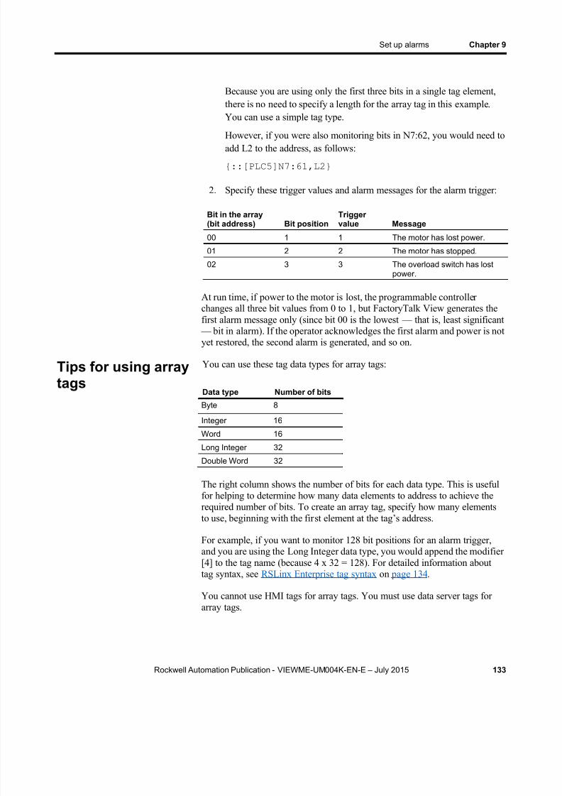
8/15/2019 Factory Talk View ME
http://slidepdf.com/reader/full/factory-talk-view-me 133/635
Set up alarms Chapter 9
Rockwell Automation Publication - VIEWME-UM004K-EN-E – July 2015 133
Because you are using only the first three bits in a single tag element,there is no need to specify a length for the array tag in this example.You can use a simple tag type.
However, if you were also monitoring bits in N7:62, you would need toadd L2 to the address, as follows:
{::[PLC5]N7:61,L2}
2. Specify these trigger values and alarm messages for the alarm trigger:
Bit in the array(bit address) Bit position
Triggervalue Message
00 1 1 The motor has lost power.
01 2 2 The motor has stopped.
02 3 3 The overload switch has lostpower.
At run time, if power to the motor is lost, the programmable controllerchanges all three bit values from 0 to 1, but FactoryTalk View generates thefirst alarm message only (since bit 00 is the lowest — that is, least significant
— bit in alarm). If the operator acknowledges the first alarm and power is notyet restored, the second alarm is generated, and so on.
You can use these tag data types for array tags:
Data type Number of bits
Byte 8Integer 16
Word 16
Long Integer 32
Double Word 32
The right column shows the number of bits for each data type. This is usefulfor helping to determine how many data elements to address to achieve therequired number of bits. To create an array tag, specify how many elementsto use, beginning with the fir st element at the tag’s address.
For example, if you want to monitor 128 bit positions for an alarm trigger,and you are using the Long Integer data type, you would append the modifier[4] to the tag name (because 4 x 32 = 128). For detailed information abouttag syntax, see RSLinx Enterprise tag syntax on page 134 .
You cannot use HMI tags for array tags. You must use data server tags forarray tags.
Tips for using arraytags

8/15/2019 Factory Talk View ME
http://slidepdf.com/reader/full/factory-talk-view-me 134/635
Chapter 9 Set up alarms
134 Rockwell Automation Publication - VIEWME-UM004K-EN-E – July 2015
Equivalent data types
Different processors and OPC servers use different terminology for tag datatypes. This section provides information about equivalent data types that youcan use for array tags, with the associated number of bits for each.
PLC and SLC tags
When creating array tags, you can use PLC and SLC tags with this data type:
Data type Number of bits
Short Integer 16
Data server tags with the Short Integer data type are shown in the TagBrowser with the Item Canonical Data Type of Integer.
To view a tag’s Item Canonical Data Type
In the Tag Browser , right-click the tag, and then select Properties .
Log ix5000 tags
When creating array tags, you can use Logix5000 tags with these data types:
Data type Number of bits
SINT 8
INT 16
DINT 32
Data server tags with the data types described in the previous table are shownin the Tag Browser with the Item Canonical Data Types of Character, ShortInteger, and Long Integer, respectively.
RSLinx Enterprise tag syntax
To create an RSLinx Enterprise array tag, use this syntax to specify thelength of the array:
{tagname,Larraylength}
For example, {::[PLC5]N7:0,L5}
The tag N7:0 uses the Short Integer data type (16 bits), so the array tagconsists of 80 bits (16 x 5).

8/15/2019 Factory Talk View ME
http://slidepdf.com/reader/full/factory-talk-view-me 135/635
Set up alarms Chapter 9
Rockwell Automation Publication - VIEWME-UM004K-EN-E – July 2015 135
When the tag name contains a colon (:), put two colons before the RSLinxEnterprise device shortcut name.
KEPServer Enterprise tag syntax
To create a KEPServer Enterprise array tag, use this syntax to specify thelength of the array:
tagname [arraylength ]
For example, Chan1.Dev1.Tag1 [3]
The tag Tag1 uses the Long Integer data type (32 bits), so the array tagconsists of 96 bits (32 x 3).
Alternatively, you can define the tag length in KEPServer Enterprise whenyou create the tag, and then just select the tag name in FactoryTalk ViewStudio. For more information, see KEPServer Enterprise Help.
FactoryTalk View 5.00 and later supports alarm messages in multiplelanguages. When you create alarm messages, they are in the currentapplication language. You can export the alarm messages for translation andthen import them back into the application. For details, see Set up languageswitching on page 197 .
Language switching alarm messages inFactoryTalk View ME Station 4.00
For applications that will run in FactoryTalk View ME Station version 4.00,use the CurrentLanguage( ) expression function to specify offsets for eachtrigger’s messages in the Alarm Setup editor. In the editor, divide themessages for each trigger into sections for each language. For informationabout the CurrentLanguage( ) function, see Language function on page 487 .
When an operator acknowledges an alarm, the acknowledge time is recordedin the alarm log file and the alarm is silenced. This might be all you requireof your alarm system.
However, you can use the optional alarm connections in the Alarm Setup editor to set up more sophisticated interactions with the data source whenalarms are triggered, acknowledged, silenced, and reset. For example, youcan set up the data source to acknowledge, silence, and reset alarms. You canalso use optional alarm connections to close the alarm display or to allow thedata source to close the alarm display.
There are two sets of optional alarm connections:
Create alarmmessages inmultiple languages
Optional alarmconnections

8/15/2019 Factory Talk View ME
http://slidepdf.com/reader/full/factory-talk-view-me 136/635
Chapter 9 Set up alarms
136 Rockwell Automation Publication - VIEWME-UM004K-EN-E – July 2015
Connections that work with a specific alarm trigger. You can assign adifferent set of connections to each alarm trigger.
Connections that apply to all alarms
You can also assign connections to alarm lists, to allow the data source todetermine which types of alarms to show in the lists. For more information,see How the alarm list graphic object works on page 150 .
You can assign a different set of these connections to each alarm trigger, orto only one or some alarm triggers:
Handshake — Assign a tag to this connection to notify the data sourcewhen the trigger’s value changes.
Ack — Assign a tag to this connection to notify the data source whenthe operator acknowledges an alarm (or all alarms).
Remote Ack — Assign a tag or an expression to this connection toallow the data source to acknowledge alarms.
Remote Ack Handshake — Assign a tag to this connection to notifythe data source when a remote acknowledgement occurs.
Message — Assign a tag to this connection to send alarm messages tothe connection. Make sure the tag supports the type of data sent in thealarm message. For example, if the message is a string of text, assign astring tag to the Message connection.
Message Notification — Assign a tag to this connection to notifyFactoryTalk View that an alarm message has been sent to the
connection and FactoryTalk View must wait before sending a newmessage.
Message Handshake — Assign a tag to this connection if you wantthe data source to notify FactoryTalk View when it has read themessage.
Assign tags or expressions to these connections when you create your alarmtriggers. For more detailed information about how these connections work,see the next sections.
How the Handshake connection worksThe Handshake connection is useful for triggers that use the Value datatype. Program the data source to queue alarm notifications when multiplealarms are generated for the same trigger. Use the Handshake connection tonotify the data source that FactoryTalk View has detected the alarmnotification. Then the data source can send the next alarm to FactoryTalkView.
Connections thatwork with a specificalarm trigger
8/15/2019 Factory Talk View ME
http://slidepdf.com/reader/full/factory-talk-view-me 137/635
Set up alarms Chapter 9
Rockwell Automation Publication - VIEWME-UM004K-EN-E – July 2015 137
When the application starts, the Handshake connection has a value of 1.When the trigger connection’s value changes, the Handshake connection’svalue toggles from 1 to 0. The next time the trigger value changes, theHandshake connection’s value toggles from 0 to 1.
A change in the trigger connection’s value does not necessarily indicate analarm. The value might still be within acceptable limits.
How the Ack connection works
When the application starts, this connection has a value of 0.
How the va lue changes
When the operator acknowledges an alarm by pressing theacknowledge alarm button, FactoryTalk View sends the alarm’s triggervalue (or bit position, for bit triggers) to this connection, and holds thevalue as long as the operator presses the button, or for the duration ofthe hold time, whichever is longer. Then the connection’s value is resetto 0.
When the operator acknowledges all alarms, or the alarms for thistrigger only, by pressing the acknowledge all alarms button,FactoryTalk View sends the trigg er’s Acknowledge all value to thisconnection, and holds the value as long as the operator presses the
button, or for the duration of the hold time, whichever is longer. Thenthe connection’s value is reset to 0.
When the Remote Ack connection changes to a new non-zero valuethat matches the trigger value of an unacknowledged alarm,FactoryTalk View sends the trigger’s value (or bit position, for bittriggers) to this connection, and holds the value for the duration of thehold time. Then the connection’s v alue is reset to 0.
To avoid confusion about whether a specific trigger’s alarm individual alarmhas been acknowledged or all alarms for the trigger have beenacknowledged, make sure the Acknowledge all value is not the same as oneof the trigger values.
How the Remote Ack connection works
The Remote Ack connection allows for the remote acknowledgement ofalarms. The data source writes the alarm’s trigger value (or bit position, for
bit triggers) to this connection, and the unacknowledged alarm with thistrigger value is acknowledged.

8/15/2019 Factory Talk View ME
http://slidepdf.com/reader/full/factory-talk-view-me 138/635

8/15/2019 Factory Talk View ME
http://slidepdf.com/reader/full/factory-talk-view-me 139/635
Set up alarms Chapter 9
Rockwell Automation Publication - VIEWME-UM004K-EN-E – July 2015 139
At run time, when an alarm with the trigger value 1 is generated, the alarmmessage appears at both locations simultaneously. If the operatoracknowledges the alarm at Location 1, FactoryTalk View writes the value 1to the Ack connection.
Since the Ack connection is write-only (not read), the acknowledgementdoes not appear at Location 2. However, the programmable controller writesthe value from the Ack connection (1) to the Remote Ack connection, andthe alarm at Location 2 is acknowledged.
How the Remote Ack Handshake connection works
This connection is used to notify the data source that the remoteacknowledgement has been detected by FactoryTalk View.
When the application starts, the Remote Ack Handshake connection has avalue of 1. When the Remote Ack connection value changes, the RemoteAck Handshake connection value toggles from 1 to 0. The next time theRemote Ack value changes, the Remote Ack Handshake value togglesfrom 0 to 1.
The Remote Ack Handshake value toggles whether or not the new RemoteAck value matches a trigger value.
This section explains how the Message , Message Notification , and MessageHandshake connections work.
To ensure an alarm message is read by the data source before FactoryTalkView sends a new message, use message handshaking. While messagehandshaking is in effect for an alarm message, FactoryTalk View cannotsend a new message to the alarm trigger’s Message connection.
Methods of alarm message handshaking
Alarm handshaking works by setting the alarm trigger’s MessageNotification connection to 1. As long as the Message Notification connection is set to 1, new messages cannot be sent to the Messagesconnection. How the Message Notification connection is reset to 0 dependson how you set up alarm message handshaking.
There are two ways you can use alarm message handshaking:
To hold the message at the data source for a specific period of time.
To hold the message at the data source until the data source notifiesFactoryTalk View that the message has been read.
Ensure alarmmessages are readby the data sourcebefore sending newmessages

8/15/2019 Factory Talk View ME
http://slidepdf.com/reader/full/factory-talk-view-me 140/635
Chapter 9 Set up alarms
140 Rockwell Automation Publication - VIEWME-UM004K-EN-E – July 2015
Choose the method that best suits your application needs and communicationsystem.
Hold the message for a specific period of time
To set up an alarm trigger’s alarm message handshaking so that the messageat the Message connection is held for a specific period of time, assign a tagto the Message Notification connection and specify a hold time in theAdvanced tab of the Alarm Setup editor.
How handshak ing works
This method of alarm message handshaking works as follows:
1. When an alarm occurs, the alarm message is sent to the Messageconnection.
2. The Message Notification connection is set to 1.
As long as the Message Notification connection is set to 1,FactoryTalk View cannot send new messages to the data source.
3. The hold time timer begins timing.
4. When the hold time has expired, the Message Notification connectionis reset to 0 and FactoryTalk View can send a new message to the
Message connection.
Hold the message until the data sourceacknowledges that it has read the message
To set up an alarm trigger’s alarm message handshaking so tha t the messageat the Message connection is held until the data source notifies FactoryTalkView that it has read the message, use two connections: the MessageNotification connection and the Message Handshake connection.
Set up the data source to send a new non-zero value to the MessageHandshake connection when it has read the message at the Messageconnection.
How handshak ing works
If you use the Message Handshake connection, handshaking works like this:
1. When an alarm occurs, the alarm message is sent to the Messageconnection.
8/15/2019 Factory Talk View ME
http://slidepdf.com/reader/full/factory-talk-view-me 141/635
Set up alarms Chapter 9
Rockwell Automation Publication - VIEWME-UM004K-EN-E – July 2015 141
2. The Message Notification connection is set to 1.
As long as the Message Notification connection is set to 1,FactoryTalk View cannot send new messages to the data source.
3. When the data source has read the message, it sends a new non-zerovalue to the Message Handshake connection.
4. The Message Notification connection is reset to 0 and FactoryTalkView can send a new message to the Message connection.
How messages are queued
FactoryTalk View can queue up to 128 messages while it waits for theMessage Notification connection to be reset to 0. Queued messages are sentto the data source on a first in, first out basis.
If the alarm message queue fills before the Message Notification connectionis reset to 0, an error message is sent to FactoryTalk Diagnostics.
How the Message connection works
This connection is used to send the message associated with a trigger value tothe data source.
The message is sent only if the alarm message’s Message to Tag option isselected.
If you are going to generate text alarm messages in multiple languages, makesure the tag assigned to this connection can accommodate the string length ofthe messages in each language. For information about using multiplelanguages, see Set up language switching on page 197 .
How the Message Notification connection works
This connection is used to notify FactoryTalk View that an alarm messagehas been sent to the data source and FactoryTalk View must wait to sendanother message.
When the application starts, the Message Notification connection is set to 0.When a message is written to the Message connection, the MessageNotification connection value changes to 1. When the hold time expires, orthe Message Handshake connection changes to a new non-zero value, theMessage Notification connection value changes from 1 to 0.
8/15/2019 Factory Talk View ME
http://slidepdf.com/reader/full/factory-talk-view-me 142/635
Chapter 9 Set up alarms
142 Rockwell Automation Publication - VIEWME-UM004K-EN-E – July 2015
Messages for an alarm trigger are queued if the Message Notification connection is set to 1.
How the Message Handshake connection works
Use the Message Handshake connection to reset the Message Notification connection when the data source has read the alarm message.
Set up the data source to send a new non-zero value to the MessageHandshake connection when it has read the message at the Messageconnection.
These connections apply to all alarms:
Silence — Assign a tag to this connection to notify the data source thatall alarms have been silenced (for applications that will run on a
personal computer only).
Remote Silence — Assign a tag or an expression to this connection toallow the data source to silence all alarms (for applications that will runon a personal computer only).
Remote Ack All — Assign a tag to this connection to allow the datasource to acknowledge all alarms at once.
Status Reset — Assign a tag to this connection to notify the datasource that the alarm status has been reset.
Remote Status Reset — Assign a tag or expression to this connectionto allow the data source to reset the alarm status.
Close Display — Assign a tag to this connection to notify the datasource that the alarm display has closed.
Remote Close Display — Assign a tag or expression to thisconnection to allow the data source to close the alarm display.
Assign tags or expressions to these connections in the Advanced tab of theAlarm Setup editor. For more detailed information about how theseconnections work, see the next sections.
How the Silence connection works
When the application starts, this connection has a value of 0. When alarmsare silenced, this connection is set to 1 for the hold time and the internal
beeper is turned off. At the end of the hold time, the connection is reset to 0.
If the silence event is triggered by a button press, this connection is set to 1for the hold time or for the duration of the button press, whichever is longer.At the end of this time, the connection is reset to 0.
Connections thatapply to all alarms
8/15/2019 Factory Talk View ME
http://slidepdf.com/reader/full/factory-talk-view-me 143/635
Set up alarms Chapter 9
Rockwell Automation Publication - VIEWME-UM004K-EN-E – July 2015 143
If subsequent alarms (that have been set up to sound the internal beeper) aregenerated, the alarms sound the beeper regardless of the Silence connectionvalue or hold time status.
While the hold time is in effect, new alarms cannot be silenced.
How the Remote Silence connection works
When this connection changes to a new non-zero value, all alarms aresilenced. Alarms can be silenced using other methods regardless of thisconnection’s value.
Set up the data source to send a new non-zero value to the Remote Silence connection each time you want a remote silencing of alarms to take place.
How the Remote Ack All connection works
When this connection changes to a new non-zero value, all unacknowledgedalarms are acknowledged.
Set up the data source to send a new non-zero value to the Remote Ack Allconnection each time you want a remote acknowledgement of all alarms totake place.
How the Status Reset connection worksWhen the application starts, this connection has a value of 0. If a reset alarmstatus or clear alarm history button is pressed, this connection is set to 1 forthe hold time or for the duration of the button press, whichever is longer. Atthe end of this time, the connection is reset to 0.
The Status Reset connection is also set to 1 if the Remote Status Reset connection changes to a new non-zero value, and remains set for the holdtime.
While the hold time is in effect, the alarm status cannot be reset again. The
status of alarms keeps updating during the hold time.
How the Remote Status Reset connection works
When this connection changes to a new non-zero value, the status of allalarms is reset, as described on Methods for resetting alarms on page 127 . Alarms can be reset using other methods regardless of this connection’svalue.

8/15/2019 Factory Talk View ME
http://slidepdf.com/reader/full/factory-talk-view-me 144/635
Chapter 9 Set up alarms
144 Rockwell Automation Publication - VIEWME-UM004K-EN-E – July 2015
Set up the data source to send a new non-zero value to the Remote StatusReset connection each time you want a remote resetting of alarm status totake place.
How the Close Display connection works
When the application starts, this connection has a value of 0. If the alarmdisplay (assigned in the Alarm Setup editor) closes, this connection is setto 1 for the hold time. At the end of the hold time, the connection is resetto 0.
If subsequent alarms are generated, the alarm display opens again regardlessof the Close Display connection value or hold time status.
How the Remote Close Display connection works
When this connection changes to a new non-zero value, the alarm displaycloses. The alarm display can be closed using other methods regardless ofthis connection’s value.
Set up the data source to send a new non-zero value to the Remote CloseDisplay connection each time you want a remote closing of the alarm displayto take place.
When you create an application, it comes with a graphic display called
[ALARM]. The [ALARM] display is the default display for showing alarmmessages at run time. It contains an alarm banner graphic object that is set upto show a single active alarm.
You can use the [ALARM] display as is, or modify the display. For example,you can change the color of the objects, or add and remove buttons.
Another option is to create your own graphic display to use when an alarmoccurs, as described on Create your own alarm display on page 149 . Or, youcan use one of the alarm displays in the graphic library. These displays aredescribed in the next four sections.
A copy of the [ALARM] display is included in the graphic library, with thename [ALARM BANNER].
The [ALARM]display

8/15/2019 Factory Talk View ME
http://slidepdf.com/reader/full/factory-talk-view-me 145/635
Set up alarms Chapter 9
Rockwell Automation Publication - VIEWME-UM004K-EN-E – July 2015 145
The alarm banner graphic object
The [ALARM] display contains an alarm banner graphic object, which liststhe most recent alarm message. You can set up the alarm banner to queuenew alarms until the shown alarm has been acknowledged, or to show newalarms as they occur. The alarm banner in the [ALARM] display is set up toshow new alarms as they occur and to show active alarms only (but you canedit it, if desired).
For more information about the alarm banner, see How the alarm bannergraphic object works on page 152 .
Buttons in the [ALARM] display
The [ALARM] display contains alarm buttons for acknowledging, silencing,and clearing alarms, as well as a button for closing the display. Forinformation about how the buttons work, see Use buttons with the alarmhistory and alarm objects on page 154 .
The Libraries folder contains a graphic display called [ALARM BANNER].The [ALARM BANNER] display allows the operator to see a single alarm ata time.
The alarm banner graphic object
The [ALARM BANNER] display contains an alarm banner graphic object,which lists the most recent alarm message. You can set up the alarm bannerto queue new alarms until the shown alarm has been acknowledged, or toshow new alarms as they occur. The alarm banner in the [ALARMBANNER] display is set up to show new alarms as they occur and to showactive alarms only (but you can edit it, if desired).
For more information about the alarm banner, see How the alarm bannergraphic object works on page 152 .
Buttons in the [ALARM BANNER] display
The [ALARM BANNER] display contains alarm buttons for acknowledging,clearing, and silencing alarms, as well as a button for closing the display. For
The [ALARMBANNER] display

8/15/2019 Factory Talk View ME
http://slidepdf.com/reader/full/factory-talk-view-me 146/635
Chapter 9 Set up alarms
146 Rockwell Automation Publication - VIEWME-UM004K-EN-E – July 2015
information about how the buttons work, see Use buttons with the alarmhistory and alarm objects on page 154 .
The Libraries folder contains a graphic display called [ALARM
MULTI-LINE]. The [ALARM MULTI-LINE] display allows the operator tosee multiple alarms at once.
You can use the [ALARM MULTI-LINE] display as is, or modify the
display. For example, you can select which alarm triggers’ alarms t o show inthe list.
The alarm list graphic object
The [ALARM MULTI-LINE] display contains an alarm list graphic object,which lists the time the alarms occurred and were acknowledged, as well asthe alarm messages. You can set up the alarm list to show any combinationof active, inactive, acknowledged, and unacknowledged alarms. The alarmlist in the [ALARM MULTI-LINE] display is set up to show all alarms (butyou can edit it, if desired).
For more information about the alarm list, see How the alarm list graphicobject works on page 150 .
Buttons in the [ALARM MULTI-LINE] display
The [ALARM MULTI-LINE] display contains alarm buttons foracknowledging and silencing alarms, as well as buttons for scrolling the listand closing the display. For information about how the buttons work, see Use
buttons with the alarm history and alarm objects on page 154 .
The [ALARMMULTI-LINE] display
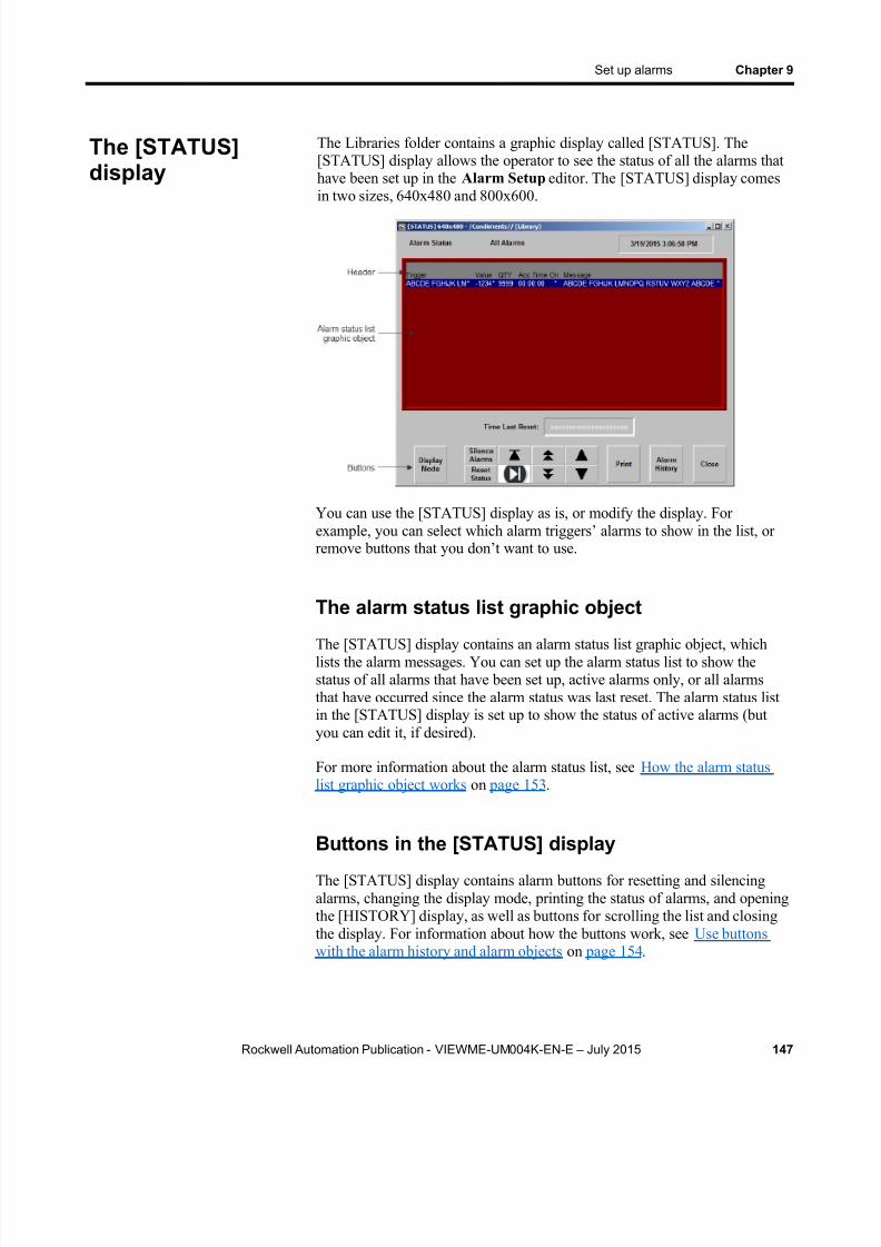
8/15/2019 Factory Talk View ME
http://slidepdf.com/reader/full/factory-talk-view-me 147/635
Set up alarms Chapter 9
Rockwell Automation Publication - VIEWME-UM004K-EN-E – July 2015 147
The Libraries folder contains a graphic display called [STATUS]. The[STATUS] display allows the operator to see the status of all the alarms thathave been set up in the Alarm Setup editor. The [STATUS] display comesin two sizes, 640x480 and 800x600.
You can use the [STATUS] display as is, or modify the display. Forexample, you can select which alarm triggers’ alarms to show in the list, orremove buttons that you don’t want to use.
The alarm status list graphic object
The [STATUS] display contains an alarm status list graphic object, whichlists the alarm messages. You can set up the alarm status list to show thestatus of all alarms that have been set up, active alarms only, or all alarmsthat have occurred since the alarm status was last reset. The alarm status listin the [STATUS] display is set up to show the status of active alarms (butyou can edit it, if desired).
For more information about the alarm status list, see How the alarm statuslist graphic object works on page 153 .
Buttons in the [STATUS] displayThe [STATUS] display contains alarm buttons for resetting and silencingalarms, changing the display mode, printing the status of alarms, and openingthe [HISTORY] display, as well as buttons for scrolling the list and closingthe display. For information about how the buttons work, see Use buttonswith the alarm history and alarm objects on page 154 .
The [STATUS]display

8/15/2019 Factory Talk View ME
http://slidepdf.com/reader/full/factory-talk-view-me 148/635

8/15/2019 Factory Talk View ME
http://slidepdf.com/reader/full/factory-talk-view-me 149/635

8/15/2019 Factory Talk View ME
http://slidepdf.com/reader/full/factory-talk-view-me 150/635
Chapter 9 Set up alarms
150 Rockwell Automation Publication - VIEWME-UM004K-EN-E – July 2015
connection’ s value matches a trigger value (if you selected the Display option for the trigger value).
You can also create a Goto display button that the operator can press to open
the alarm display. For information about setting up a Goto display button andspecifying the display to open, see Help.
Close the display
The operator can close the display by pressing a Close Display button.
The display closes automatically under these circumstances:
When the operator presses an acknowledge all alarms button andcauses the newest alarm in the alarm history to be acknowledged.
When the operator presses a clear alarm history button and causes thenewest alarm in the alarm history to be deleted.
When the Remote Close Display connection changes to a newnon-zero value.
When the Remote Ack All connection changes to a new non-zerovalue.
When the newest alarm is acknowledged.
If you don’t want the display to close when the newest alarm isacknowledged, you can turn off this option in FactoryTalk View ME Station.
To change how the d isplay c loses
1. In FactoryTalk View ME Station, click Terminal Settings .
2. Double-click Alarms .
3. Specify how you want the display to close.
The alarm list graphic object displays the time an alarm was triggered, andthe time it was acknowledged (if you set up the object to showacknowledged alarms).
At run time, when a trigger connection at the data source matches amessage’s trigger value, an alarm appears in t he alarm list. The alarm list can
be in the [ALARM MULTI-LINE] or [HISTORY] display, in an alarmdisplay you have created, or can be placed on any display in your application.
You can use multiple alarm lists, in the same display or in different displays.Each alarm list displays information from the same alarm log file, althoughyou can set up different lists to display different information.
How the alarm listgraphic objectworks

8/15/2019 Factory Talk View ME
http://slidepdf.com/reader/full/factory-talk-view-me 151/635
Set up alarms Chapter 9
Rockwell Automation Publication - VIEWME-UM004K-EN-E – July 2015 151
For information about setting up alarm lists, see Help.
What is shown
If you set up the list to show the alarms for specific alarm triggers, onlyalarms for those triggers are displayed.
If the list is set up to show unacknowledged alarms only, the alarmsshown in the list are unacknowledged and the acknowledge timecolumn, if any, is always blank.
If the list is set up to show both acknowledged and unacknowledgedalarms, acknowledged alarms can show a symbol (which you canspecify) at the left end of the row, and the acknowledge time appears inthe acknowledge time column, if shown.
If the list is set up to show both active and inactive alarms, activealarms can show a symbol (which you can specify) at the left end ofthe row. If both the acknowledge symbol and active symbol are shown,the active symbol column is to the right of the acknowledge symbolcolumn.
If the message is too long to fit in the object, the last shown character isreplaced with an asterisk. Similarly, if a column heading is too long tofit in the column, the last displayed character is replaced with anasterisk. You can specify how many lines to allow for each alarmmessage, from 1 to 10.
The number of alarm messages that fits in the display depends on the
height of the alarm list, the list’s font size, how many lines you havespecified for each alarm message, and whether the column headingsare shown.
If alarms are currently being sorted by time, alarms are listed with thenewest alarms on top.
If alarms are currently being sorted by trigger value, alarms from thefirst trigger in the Alarm Setup editor are listed first, with alarms fromsubsequent triggers listed after. Alarms in the list from the same triggerare grouped together and then sorted by trigger value, from lowest tohighest.
If there are multiple instances of the same alarm, these alarms aresorted by time with the newest on top.
If you assign a tag or expression to any of the ActiveAcknowledged,ActiveUnacknowledged, InactiveAcknowledged, orInactiveUnacknowledged connections, when a connection’s value is anon-zero value, the related type of alarm is displayed in the alarm list.The connection value overrides the setting for the list in the AlarmList Properties dialog box.
If you set up alarm messages in multiple languages, messages areshown in the language that they were originally logged in. All alarm
8/15/2019 Factory Talk View ME
http://slidepdf.com/reader/full/factory-talk-view-me 152/635
Chapter 9 Set up alarms
152 Rockwell Automation Publication - VIEWME-UM004K-EN-E – July 2015
and acknowledgement times are displayed in the current applicationlanguage.
How the list scrolls
When a display containing an alarm list is opened, the highlight bar orcursor is at the top of the list: on the most recent alarm if sorted bytime; or on the first alarm for the first trigger, if sorted by trigger value.
If alarms are sorted by time, and the top alarm is selected, as newalarms occur, the old alarms scroll down, but the highlight bar orcursor remains at the top.
If alarms are sorted by time, when the operator selects an alarm otherthan the top one in the list (by using the move down button), and newalarms occur, they are added above the visible area if the list is full.The currently selected alarm continues to be selected and maintains its
position in the displayed portion of the list.
If alarms are sorted by trigger value, as new alarms occur the currentlyselected alarm continues to be selected and maintains its position in thelist.
If the sort order changes, the selected alarm continues to be selected, but it might be displayed in a different position in the list.
The alarm banner graphic object shows a single, unacknowledged alarm.
At run time, when a trigger connection at the data source matches amessage’s trigger value, an alarm appears in the alarm banner. The alarm
banner can be in the [ALARM] display or [ALARM BANNER] display, inan alarm display you have created, or can be placed on any display in yourapplication.
You can use multiple alarm banners, in the same display or in differentdisplays. You can set up different banners so that one displays the mostrecent alarm, and the other queues alarms until the displayed alarm isacknowledged.
For information about setting up alarm banners, see Help.
What is shown
If you set up the banner to show the alarms for specific alarm triggers,only alarms for those triggers are displayed.
You can set up the banner to queue new alarms until the operator clearsthe current alarm, or to always display the most recent alarm.
How the alarmbanner graphic
object works

8/15/2019 Factory Talk View ME
http://slidepdf.com/reader/full/factory-talk-view-me 153/635
Set up alarms Chapter 9
Rockwell Automation Publication - VIEWME-UM004K-EN-E – July 2015 153
When a display containing an alarm banner is first opened, the alarm banner is blank, unless the display is the alarm display specified in theAlarm Setup editor and it was opened in response to an alarm.
When the shown alarm is acknowledged, it is removed from the alarm banner. If there are no newer alarms, the banner is blank.
If the operator presses a clear alarm banner button, the banner is blank.
If the operator presses a clear alarm history button or if all alarms areacknowledged, the banner is blank.
If the banner is set up to show both active and inactive alarms, when analarm is active, an asterisk (*) appears beside the message.
If you set up alarm messages in multiple languages, messages andtrigger labels are shown in the language that they were originallylogged in. All alarm times are shown in the current application
language.
The alarm status list graphic object shows the status of alarms, includingwhether an alarm has been triggered, how many times an alarm has beentriggered, and for how long.
The alarm status list can be in the [STATUS] display, in an alarm displayyou have created, or can be placed on any display in your application.
You can use multiple alarm status lists, in the same display or in differentdisplays. You can set up different lists to show different information.
For information about setting up alarm status lists, see Help.
What is shown
If you set up the list to show the alarms for specific alarm triggers, onlyalarms for those triggers are shown.
If an alarm is active, an asterisk (*) appears in the alarm state column,if shown.
If the message is too long to fit in the object, the last character thatwould fit is replaced with an asterisk. Similarly, if a column heading is
too long to fit in the column, the last character that would fit isreplaced with an asterisk. You can specify how many lines to allow foreach alarm message, from 1 to 10.
The number of alarm messages that fits in the display depends on theheight of the alarm status list, the list’s font size, how many lines youhave specified for each alarm message, and whether the columnheadings are displayed.
For value-triggered alarms, the accumulated time column shows howlong the alarm has been set to the trigger value.
How the alarmstatus list graphicobject works
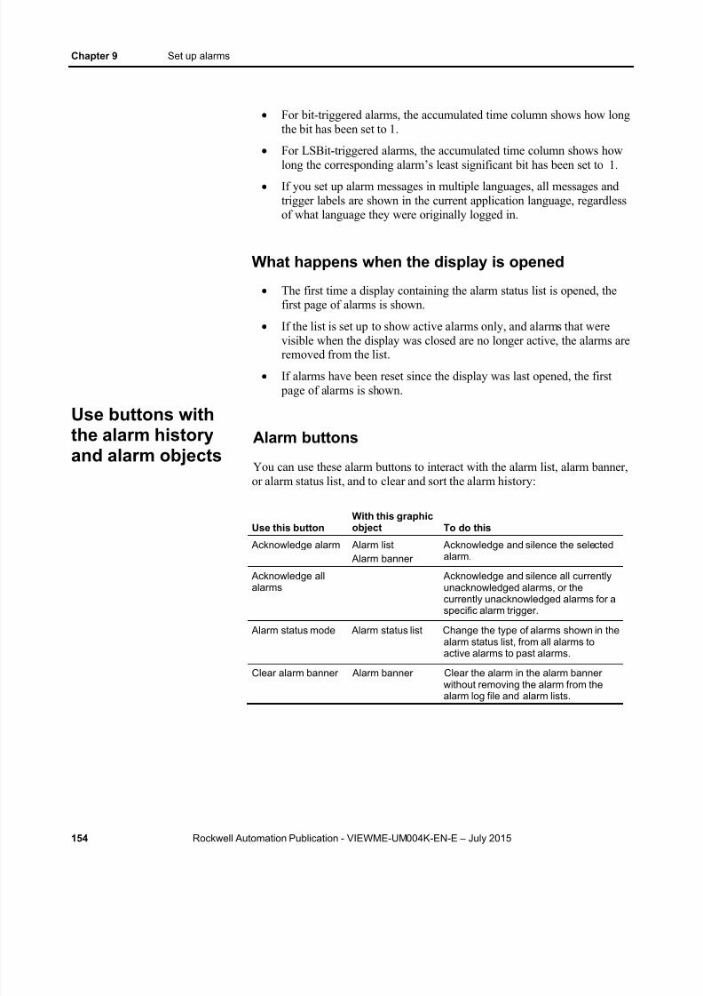
8/15/2019 Factory Talk View ME
http://slidepdf.com/reader/full/factory-talk-view-me 154/635

8/15/2019 Factory Talk View ME
http://slidepdf.com/reader/full/factory-talk-view-me 155/635
Set up alarms Chapter 9
Rockwell Automation Publication - VIEWME-UM004K-EN-E – July 2015 155
Use this buttonWith this graphicobject To do this
Clear alarm history Remove alarms from the alarm log fileand all alarm lists. If the Ackconnection is assigned for any of thealarm triggers, the operator is promptedto acknowledge all alarms beforeclearing them.You can set up the button to remove allalarms, or just the alarms for a specificalarm trigger. You can also specifywhether to reset the cleared alarms.If you choose to reset alarms, pressingthis button resets the number of timesan alarm has been triggered to 0, andthe accumulated time in alarm to 0, forall alarms that are being cleared. If thealarm is still active, the number of times
in alarm changes to 1 after the alarm isreset to 0.
Print alarm history Print a report of the alarm messages inthe alarm log file. You can include allalarms, or just the alarms for a specificalarm trigger. The report can includethe time alarms occurred and wereacknowledged.
Print alarm status Print a report of the status of alarms.You can include all alarms, or just thealarms for a specific alarm trigger. Thereport can include how many timeseach alarm was triggered, and theaccumulated time in alarm.
Reset alarm status Reset the number of times an alarmhas been triggered to 0, and theaccumulated time in alarm to 0, for allalarms. If the alarm is still active, thenumber changes to 1.
Silence alarms Silence the audio indictor for all alarms(for applications that will run on apersonal computer only).
Sort alarms Toggle between sorting alarms in alarmlists and the alarm log file by time andby trigger value.
You can assign any caption you choose to the labels on the alarm buttons.
Link alarm buttons to objects
You can link the acknowledge alarm button to a specific alarm list or alarm banner, or set up the button to work with whichever alarm list or alarm banner is selected in the graphic display.
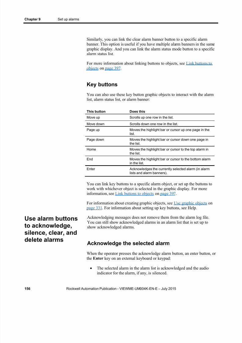
8/15/2019 Factory Talk View ME
http://slidepdf.com/reader/full/factory-talk-view-me 156/635
Chapter 9 Set up alarms
156 Rockwell Automation Publication - VIEWME-UM004K-EN-E – July 2015
Similarly, you can link the clear alarm banner button to a specific alarm banner. This option is useful if you have multiple alarm banners in the samegraphic display. And you can link the alarm status mode button to a specificalarm status list.
For more information about linking buttons to objects, see Link buttons toobjects on page 397 .
Key buttons
You can also use these key button graphic objects to interact with the alarmlist, alarm status list, or alarm banner:
This button Does this
Move up Scrolls up one row in the list.Move down Scrolls down one row in the list.
Page up Moves the highlight bar or cursor up one page in thelist.
Page down Moves the highlight bar or cursor down one page inthe list.
Home Moves the highlight bar or cursor to the top alarm inthe list.
End Moves the highlight bar or cursor to the bottom alarmin the list.
Enter Acknowledges the currently selected alarm (in alarmlists and alarm banners).
You can link key buttons to a specific alarm object, or set up the buttons towork with whichever object is selected in the graphic display. For moreinformation, see Link buttons to objects on page 397 .
For information about creating graphic objects, see Use graphic objects on page 331 . For information about setting up key buttons, see Help.
Acknowledging messages does not remove them from the alarm log file.You can still show acknowledged alarms in an alarm list that is set up toshow acknowledged alarms.
Acknowledge the selected alarm
When the operator presses the acknowledge alarm button, an enter button, orthe Enter key on an external keyboard or keypad:
The selected alarm in the alarm list is acknowledged and the audioindicator for the alarm, if any, is silenced.
Use alarm buttonsto acknowledge,
silence, clear, anddelete alarms

8/15/2019 Factory Talk View ME
http://slidepdf.com/reader/full/factory-talk-view-me 157/635
Set up alarms Chapter 9
Rockwell Automation Publication - VIEWME-UM004K-EN-E – July 2015 157
The shown alarm in the alarm banner is acknowledged and the audioindicator for the alarm, if any, is silenced.
This is what happens when the alarm is acknowledged:
If assigned, the alarm trigger’s Ack connection is set to the alarmtrigger value at the data source. The value is held as long as theoperator presses the button, or for the hold time, whichever is longer.
If the hold time is still in effect and the operator acknowledges a newinstance of the same alarm, the new acknowledgement is ignored.
If the alarm list is set up to show unacknowledged alarms only, thealarm is removed from the list. The highlight bar or cursor moves up tothe next unacknowledged alarm, unless it is already on the topunacknowledged alarm.
If the highlight bar or cursor is on an acknowledged alarm when theoperator presses the acknowledge alarm button, the button press isignored.
The alarm is removed from the alarm banner.
Acknowledge all alarms
When the operator presses an acknowledge all alarms button, allunacknowledged alarms in the system (or, optionally, for a specific alarmtrigger), are acknowledged.
This is what happens when the alarms are acknowledged:
For each alarm trigger, to which an Acknowledge all value is assigned,the specified Acknowledge all value is sent to the trigger’s Ackconnection . The value is held as long as the operator presses the
button, or for the hold time, whichever is longer. Then the connection’svalue is reset to 0.
If the Acknowledge all value is not assigned for a trigger, no value issent to the trigger’s Ack connection .
If the hold time for any alarm is still in effect and the operator presses
acknowledge all alarms, the button press is ignored. If the alarm list is set up to display unacknowledged alarms only, all
acknowledged alarms are removed from the list.
The alarm banner is cleared.
8/15/2019 Factory Talk View ME
http://slidepdf.com/reader/full/factory-talk-view-me 158/635
Chapter 9 Set up alarms
158 Rockwell Automation Publication - VIEWME-UM004K-EN-E – July 2015
Silence alarms
When the operator presses the silence alarms button, any audible signaltriggered by an alarm is silenced and the Silence connection is set to 1 for thehold time or for the duration of the button press, whichever is longer. Thenthe connection’s value is reset to 0.
If the hold time for any alarm is still in effect and the operator presses silencealarms, the button press is ignored.
The audio alarm indicator is available for applications running on personalcomputers only.
Clear and delete messages
From the a larm h is tory
When the operator presses the clear alarm history button, all alarms in thesystem (or, optionally, for a specific alarm trigger) are deleted from the alarmlog file and from all alarm lists. For information about the alarm log file, seeThe alarm log file on page 129 .
If the Ack connection is assigned for any of the alarm triggers being cleared,the operator is prompted to acknowledge the unacknowledged messages
before deleting them. If the operator chooses to acknowledge the alarms, theAcknowledge all value (if any) is sent to the Ack connection before deleting
the messages. If the Ack connection is not assigned, or if the operatorchooses not to acknowledge alarms, all messages are deleted immediately.
From the a larm banner
When the operator presses the clear alarm banner button, the shown alarm iscleared from the banner. The alarm remains in the alarm log file and in allalarm lists it appears in.
Sort alarms
When the operator presses the sort alarms button, the sort order toggles fromtime to trigger value or from trigger value to time. The sort order applies toall alarms in all alarm lists and in the alarm log file.
Reset alarm status
When the operator presses the reset alarm status button, the alarm status ofeach alarm is reset as follows:
Use alarm buttonsto sort alarms and
reset alarm status

8/15/2019 Factory Talk View ME
http://slidepdf.com/reader/full/factory-talk-view-me 159/635
Set up alarms Chapter 9
Rockwell Automation Publication - VIEWME-UM004K-EN-E – July 2015 159
The accumulated time an alarm has been in alarm is reset to 0. If thealarm is still active, the time begins accumulating again.
The number of times the alarm has been triggered is reset to 0. If the
alarm is still active, the number changes to 1.If the Status Reset connection is assigned (in the Alarm Setup editor), it isset to 1 for the hold time or for the duration of the button press, whichever islonger. If a hold time from a previous reset alarm status button press is still ineffect, the button press is ignored.
Pressing the clear alarm history button can also reset the status of alarms, ifyou select the Reset alarm status option for the button. You can set the
button up to clear and reset the status of all alarms, or just the alarms for aspecific alarm trigger.
Retain alarm status
The status of alarms is retained when the application is shut down. When theapplication is restarted:
If an alarm is still active, the time begins accumulating again.
If an alarm is still active, the number of times the alarm has beentriggered is increased by 1.
Change the alarm status shown in the alarm statuslist
When the operator presses the alarm status mode button, the type of alarmsshown in the alarm status list changes as follows:
If the current type shown is all alarms, the list changes to show activealarms only.
If the current type shown is active alarms, the list changes to show pastalarms only.
If the current type shown is past alarms, the list changes to show all
alarms.
The change affects the linked or selected alarm status list only, not all alarmstatus lists.

8/15/2019 Factory Talk View ME
http://slidepdf.com/reader/full/factory-talk-view-me 160/635
Chapter 9 Set up alarms
160 Rockwell Automation Publication - VIEWME-UM004K-EN-E – July 2015

8/15/2019 Factory Talk View ME
http://slidepdf.com/reader/full/factory-talk-view-me 161/635
Rockwell Automation Publication - VIEWME-UM004K-EN-E – July 2015 161
Chapter 10
Set up FactoryTalk Diagnostics
This chapter describes:
FactoryTalk Diagnostics
Show diagnostics messages during application development
View FactoryTalk Diagnostics log files
Use the Diagnostics Setup tool
Show and print diagnostics messages at run time
The [DIAGNOSTICS] display
Create your own diagnostics display
Open and close the diagnostics display
How the diagnostics list graphic object works
FactoryTalk Diagnostics records information about various types of systemactivity, including:
Macro usage
Operator comments
System messages and errors
Errors from the communication network
Tag read and write activity
Browse diagnostics messages
You can view diagnostics messages about system activity during application
development and at run time. For example, while you develop yourapplication, use diagnostics messages to track what the system is doing andto ensure you have set things up the way you intend. At run time, usediagnostics messages to show the operator messages about system activity.You can also save information in a log file for future processing or analysis.
About FactoryTalkDiagnostics

8/15/2019 Factory Talk View ME
http://slidepdf.com/reader/full/factory-talk-view-me 162/635
Chapter 10 Set up FactoryTalk Diagnostics
162 Rockwell Automation Publication - VIEWME-UM004K-EN-E – July 2015
How to set up FactoryTalk Diagnostics
You must set up FactoryTalk Diagnostics on both the development computerand the runtime computer. The settings for FactoryTalk Diagnostics apply toall Rockwell Automation products installed on the computer.
Set up FactoryTalk Diagnostics involves:
Set up destinations, where logged information is received for storage ordisplay.
Set up which destinations receive which categories of messages. Thisis called message routing.
Set up how messages are shown and printed at run time.
This chapter describes how to set up FactoryTalk Diagnostics on personalcomputers. For information about setting up FactoryTalk Diagnostics on thePanelView Plus 7, PanelView Plus 6, PanelView Plus, PanelView PlusCompact, or PanelView Plus CE terminal, see the PanelView Plus TerminalsUser Manual .
Destinations
FactoryTalk Diagnostics allows you to send diagnostics messages to multipledestinations.
Dur ing appl ica t ion developm ent
During application development, you can send diagnostics messages to:
The Diagnostics List at the bottom of the FactoryTalk View Studiowindow.
A local log, which is viewable using the FactoryTalk DiagnosticsViewer tool.
An ODBC database.
At run t ime
At run time, you can send diagnostics messages to:
Diagnostics list graphic objects, either in the default [DIAGNOSTICS]display, or in a display you create.
A printer
A local log (available on personal computers only), which is viewableusing the FactoryTalk Diagnostics Viewer.
8/15/2019 Factory Talk View ME
http://slidepdf.com/reader/full/factory-talk-view-me 163/635
Set up FactoryTalk Diagnostics Chapter 10
Rockwell Automation Publication - VIEWME-UM004K-EN-E – July 2015 163
A remote log (PanelView Plus 7, PanelView Plus 6, PanelView Plus,PanelView Plus Compact, or PanelView Plus CE terminals only).
An ODBC database.
The FactoryTalk Diagnostics Viewer is available on personal computersonly. However, if you send diagnostics messages from a PanelView Plus 7,PanelView Plus 6, PanelView Plus, PanelView Plus Compact, or PanelViewPlus CE terminal to a personal computer, you can view the messages in theFactoryTalk Diagnostics Viewer.
Note: The destinations available on your computer might vary,depending on which Rockwell Automation products you haveinstalled.
Message routing
You can decide which destinations receive which kinds of messages. Thisallows you to make the right information available to the right person, in theright place.
For example:
You can send messages that contain information about what the systemis doing to the local log file. You can also send warnings about thingsthat might go wrong if left unattended to the local log file.
This allows a control systems engineer to analyze system activity and performance, and make corrections during scheduled maintenancetimes.
You can send errors that require immediate action to the diagnosticslist object in the [DIAGNOSTICS] display, as well as the log file.
You can set up the [DIAGNOSTICS] display to open automaticallywhen system activity occurs, to allow the operator to respond to
problems that might stop production if they are not solvedimmediately.
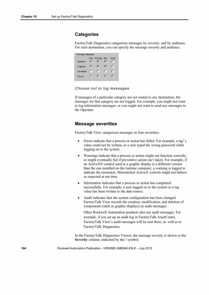
8/15/2019 Factory Talk View ME
http://slidepdf.com/reader/full/factory-talk-view-me 164/635
Chapter 10 Set up FactoryTalk Diagnostics
164 Rockwell Automation Publication - VIEWME-UM004K-EN-E – July 2015
Categories
FactoryTalk Diagnostics categorizes messages by severity, and by audience.For each destination, you can specify the message severity and audience.
Choose not to log messages
If messages of a particular category are not routed to any destination, themessages for that category are not logged. For example, you might not wantto log information messages, or you might not want to send any messages tothe Operator.
Message severities
FactoryTalk View categorizes messages in four severities:
Errors indicate that a process or action has failed. For example, a tag’ svalue could not be written, or a user typed the wrong password whilelogging on to the system.
Warnings indicate that a process or action might not function correctly,or might eventually fail if preventive action isn’t taken. For example, ifan ActiveX® control used in a graphic display is a different versionthan the one installed on the runtime computer, a warning is logged toindicate the mismatch. Mismatched ActiveX controls might not behaveas expected at run time.
Information indicates that a process or action has completedsuccessfully. For example, a user logged on to the system or a tagvalue has been written to the data source.
Audit indicates that the system configuration has been changed.
FactoryTalk View records the creation, modification, and deletion ofcomponents (such as graphic displays) as audit messages.
Other Rockwell Automation products also use audit messages. Forexample, if you set up an audit log in FactoryTalk AssetCentre,FactoryTalk View’s audit messages will be sent there, as well as toFactoryTalk Diagnostics.
In the FactoryTalk Diagnostics Viewer, the message severity is shown in theSeverity column, indicated by the ! symbol.

8/15/2019 Factory Talk View ME
http://slidepdf.com/reader/full/factory-talk-view-me 165/635
Set up FactoryTalk Diagnostics Chapter 10
Rockwell Automation Publication - VIEWME-UM004K-EN-E – July 2015 165
The content of the messages is provided by the system. You do not need todo anything to set up message content.
Audiences
FactoryTalk Diagnostics allows messages to be categorized differently forthe various people for whom the messages are relevant. You can sort themessages in the FactoryTalk Diagnostics Viewer, so that those relevant to a
particular person are grouped together.
Who receives which m essages?
You can specify which types of messages are sent to the Operator, Engineer,and Developer audiences.
FactoryTalk View automatically sends audit messages to the Engineer andSecure audiences. Audit messages allow auditing tools, such as thoserequired for US Government 21CFR Part 11 compliance, to track systemactivity.
During application development, diagnostics messages are shown as youcreate, modify, and delete components, and when you test your graphicdisplays. The messages are shown in the Diagnostics List at the bottom ofthe FactoryTalk View Studio window. You can also view the messages inthe FactoryTalk Diagnostics Viewer, as described in the next section.
By default, all warning and error messages are shown in the DiagnosticsList . To change what is shown in the Diagnostics List , use the DiagnosticsSetup tool, as described on Use the Diagnostics Setup tool on page 166 .
For information about testing graphic displays, see Test your displays as youwork on page 308 .
To show the Diagnostics List
From the View menu, select Diagnostics List . A check mark besidethe menu item indicates the Diagnostics List is shown.
For information about moving, resizing, and clearing messages in theDiagnostics List , see The Diagnostics List on page 43 .
If you don’t want to show diagnostics messages
From the View menu, select Diagnostics List . The option is turned off whenno check mark appears.
Show diagnosticsmessages duringapplicationdevelopment

8/15/2019 Factory Talk View ME
http://slidepdf.com/reader/full/factory-talk-view-me 166/635
Chapter 10 Set up FactoryTalk Diagnostics
166 Rockwell Automation Publication - VIEWME-UM004K-EN-E – July 2015
Use the FactoryTalk Diagnostics Viewer tool to view the contents ofFactoryTalk Diagnostics local log files. You can open the FactoryTalkDiagnostics Viewer from within FactoryTalk View Studio, or from theWindows Start menu.
The FactoryTalk Diagnostics Viewer is available on personal computers.
You can also set up personal computers to accept messages from PanelViewPlus 7, PanelView Plus 6, PanelView Plus, PanelView Plus Compact, orPanelView Plus CE terminals, and then show the messages in theFactoryTalk Diagnostics Viewer or in the Diagnostics List . For informationabout sending messages from PanelView Plus 7, PanelView Plus 6,PanelView Plus, PanelView Plus Compact, or PanelView Plus CE terminalsto personal computers, see Receive messages from a PanelView Plus 7,PanelView Plus 6, PanelView Plus, or PanelView Plus CE terminal on page168 .
To open the FactoryTalk Diagnostics Viewer, doone of the following
In FactoryTalk View Studio, from the Tools menu, select DiagnosticsViewer .
From the Windows Start menu, select Programs > RockwellSoftware > FactoryTalk Tools > Diagnostics Viewer .
For information about setting up FactoryTalk Diagnostics to send messages
to the local log, see Help for the Diagnostics Setup tool. For additionalinformation about setting up and using the FactoryTalk Diagnostics Viewer,see the FactoryTalk Diagnostics Viewer Help.
Use the Diagnostics Setup tool to set up:
Destinations and message routing on the development computer,including logging to the local log or to an ODBC database.
Destinations and message routing on personal computers, includingruntime logging to the local log or to an ODBC database.
The Windows CE runtime destination to receive logged messages
from.
You can also use the Diagnostics Setup tool to clear the local log file.
To open the FactoryTalk Diagnostics Setup tool,do one of the following
In FactoryTalk View Studio, from the Tools menu, select DiagnosticsSetup .
View FactoryTalkDiagnostics log files
Use the DiagnosticsSetup tool

8/15/2019 Factory Talk View ME
http://slidepdf.com/reader/full/factory-talk-view-me 167/635
Set up FactoryTalk Diagnostics Chapter 10
Rockwell Automation Publication - VIEWME-UM004K-EN-E – July 2015 167
In the FactoryTalk View ME Station dialog box, click TerminalSettings , and then double-click Diagnostics Setup .
For information about opening the FactoryTalk View ME Station
dialog box: On personal computers, see To start FactoryTalk View ME Station
on page 232 .
On a PanelView Plus 7, PanelView Plus 6, PanelView Plus,PanelView Plus Compact, or PanelView Plus CE terminal, see Tostart FactoryTalk View ME Station on a PanelView Plus 7 orPanelView Plus 6 terminal on page 250 .
From the Windows Start menu, select Programs > RockwellSoftware > Utilities > Diagnostics Setup .
For details about using the Diagnostics Setup tool, see Help for the tool.
Log to an ODBC database
The option of logging FactoryTalk Diagnostics messages to an ODBCdatabase is available for personal computers only.
ODBC logging works by periodically exporting the contents of the local logfile to an ODBC-compliant database. FactoryTalk View supports theseODBC-compliant databases:
Microsoft Access
Sybase SQL Server
Oracle
Microsoft SQL Server
8/15/2019 Factory Talk View ME
http://slidepdf.com/reader/full/factory-talk-view-me 168/635
Chapter 10 Set up FactoryTalk Diagnostics
168 Rockwell Automation Publication - VIEWME-UM004K-EN-E – July 2015
If you have set up FactoryTalk Diagnostics to overwrite events in the locallog file, make sure messages are logged to the ODBC-compliant database
before the oldest events are deleted.
For information about the contents of the FactoryTalk Diagnostics ODBCtables, see ODBC database schema on page 595 .
Set up message buffer ing
FactoryTalk Diagnostics messages are stored in the computer’s local log file,and are exported to the ODBC-compliant database at the interval youspecify.
You can also specify that messages remain in the local log file for a period oftime after they have been exported to the ODBC-compliant database. This isuseful in the event of a network failure, or any other reason that causes thedatabase to be unavailable. In this case, the messages remain in the local logfile until the buffer time expires. If the ODBC-compliant database becomesavailable during that time, the buffered messages are then exported to thedatabase.
Route messages
For each destination you set up, you can specify how messages are routed.
To route messages
You need specify:
The types of messages to log
The audiences to send the messages to
Whether to accept messages from Windows CE devices
For information about who receives which types of messages, see Whoreceives which messages? on page 165 .
Receive messages from a PanelView Plus 7,PanelView Plus 6, PanelView Plus, or PanelViewPlus CE terminal
You can set up FactoryTalk Diagnostics to receive messages that aregenerated on the PanelView Plus 7, PanelView Plus 6, PanelView Plus,PanelView Plus Compact, or PanelView Plus CE terminal at run time. Theterminal must be on the same network as the computer running FactoryTalkDiagnostics.

8/15/2019 Factory Talk View ME
http://slidepdf.com/reader/full/factory-talk-view-me 169/635
Set up FactoryTalk Diagnostics Chapter 10
Rockwell Automation Publication - VIEWME-UM004K-EN-E – July 2015 169
To receive messages:
Enable the personal computer to receive the messages. For details seeHelp for the Diagnostics Setup tool.
Set up the PanelView Plus 7, PanelView Plus 6, PanelView Plus,PanelView Plus Compact, or PanelView Plus CE terminal to send themessages.
For information about setting up a PanelView Plus 7, PanelView Plus 6,PanelView Plus, PanelView Plus Compact, or PanelView Plus CE terminalto log to the personal computer, see the PanelView Plus Terminals User
Manual .
At run time, you can show diagnostics messages in a graphic display. Youcan also print the messages.
Use the Diagnostics List Setup editor
Use the Diagnostics List Setup editor to set up when to print and showmessages at run time in FactoryTalk View ME Station.
Show and printdiagnosticsmessages at runtime

8/15/2019 Factory Talk View ME
http://slidepdf.com/reader/full/factory-talk-view-me 170/635
8/15/2019 Factory Talk View ME
http://slidepdf.com/reader/full/factory-talk-view-me 171/635
Set up FactoryTalk Diagnostics Chapter 10
Rockwell Automation Publication - VIEWME-UM004K-EN-E – July 2015 171
The messages that are printed and shown depend on how you set upFactoryTalk Diagnostics on the runtime computer:
For applications running on personal computers, use the Diagnostics
Setup tool to set up diagnostics message logging. For informationabout using the Diagnostics Setup tool, see Help.
For information about setting up FactoryTalk Diagnostics on thePanelView Plus 7, PanelView Plus 6, PanelView Plus, PanelView PlusCompact, or PanelView Plus CE terminal, see the PanelView PlusTerminals User Manual .
For applications running on personal computers, you can also view theruntime messages in the FactoryTalk Diagnostics Viewer, as described onView FactoryTalk Diagnostics log files on page 166 .
If you don’t want to show diagnostics messages inFactoryTalk View ME Station
In FactoryTalk View Studio, in the Diagnostics List Setup editor, clear theDisplay name box, or clear the four Open display automatically when
boxes.
Set up how messages are shown and printed atrun time
Follow these steps to set up how diagnostics messages are shown at run time:1. In FactoryTalk View Studio, in the Diagnostics List Setup editor,
specify which messages to print, the graphic display to use, when toopen the graphic display, and the maximum number of messages tostore.
2. If desired, modify the default [DIAGNOSTICS] display, or create yourown graphic display to use for diagnostics messages. For example, ifyou don’t want the operator to clear all messages at once, edit thedefault display to remove the clear all button.
For information about graphic displays, see Use graphic displays on page 299 .

8/15/2019 Factory Talk View ME
http://slidepdf.com/reader/full/factory-talk-view-me 172/635
Chapter 10 Set up FactoryTalk Diagnostics
172 Rockwell Automation Publication - VIEWME-UM004K-EN-E – July 2015
When you create an application, it comes with a graphic display called[DIAGNOSTICS]. The [DIAGNOSTICS] display is the default display forshowing diagnostics messages at run time.
You can use the [DIAGNOSTICS] display as is, or modify the display. Forexample, you can change the color of the objects, or add and remove buttons.Or, you can create your own graphic display to use for showing diagnosticsmessages. In the Diagnostics List Setup editor, specify the display to use.
The diagnostics list graphic object
The [DIAGNOSTICS] display contains a diagnostics list graphic object,which lists the diagnostics messages. For more information about thediagnostics list, see How the diagnostics list graphic object works on page173 .
Buttons in the [DIAGNOSTICS] display
The [DIAGNOSTICS] display contains diagnostics list buttons for clearingthe messages, as well as buttons for scrolling the list and closing the display.For information about how the buttons work, see Use buttons with thediagnostics list on page 173 .
You can create your own graphic display for showing diagnostics messages,containing a diagnostics list graphic object and the buttons the operatorneeds for using the display.
If you create your own graphic display, use an On Top display and select theCannot Be Replaced option.
For more information about the diagnostics list, see How the diagnostics listgraphic object works on page 173 . For information about the buttons you canuse with the list, see Use buttons with the diagnostics list on page 173 . Forinformation about creating graphic displays and graphic objects, see Usegraphic displays on page 299 and Use graphic objects on page 331 .
Open the display
The diagnostics display you specify in the Diagnostics List Setup editor
The [DIAGNOSTICS]display
Create your owndiagnostics display
Open and close thediagnostics display

8/15/2019 Factory Talk View ME
http://slidepdf.com/reader/full/factory-talk-view-me 173/635
Set up FactoryTalk Diagnostics Chapter 10
Rockwell Automation Publication - VIEWME-UM004K-EN-E – July 2015 173
(either the default [DIAGNOSTICS] display or a display you create) isautomatically opened whenever a diagnostics message of the specifiedseverity occurs.
The display remains open until the operator closes the display.
If you decide not to open the diagnostics display automatically, you cancreate a Goto display button that the operator can press to open thediagnostics display. For information about setting up a Goto display buttonand specifying the display to open, see Help.
Close the display
The operator can close the display by pressing a close display button.
At run time, when a severity of system activity occurs that you set up to log,a message about the activity is added to the diagnostics list. The diagnosticslist can be in the [DIAGNOSTICS] display, in a diagnostics display youhave created, or can be placed on any display in your application.
You can use multiple diagnostics lists, in the same display or in differentdisplays. Each diagnostics list shows the same information.
For information about setting up diagnostics lists, see Help.
What is shown
If the message is too long to fit in the list, the last shown character isreplaced with an asterisk (*).
The number of diagnostics messages that is visible at one time dependson the height of the diagnostics list and the list’s font size.
Messages are listed with the newest diagnostics message on top.
Use buttons with the diagnostics list
Diagnos t i c s bu t tons
You can use these diagnostics buttons to interact with the diagnostics list:
This button Does this
Diagnostics clear Clears the selected message from all diagnostics listsin the application.
Diagnostics clear all Clears all diagnostics messages from all diagnosticslists in the application.
How the diagnosticslist graphic objectworks
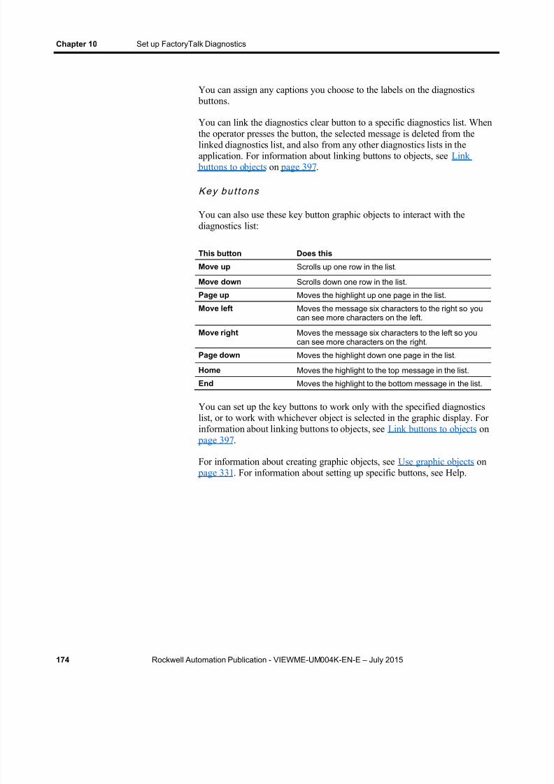
8/15/2019 Factory Talk View ME
http://slidepdf.com/reader/full/factory-talk-view-me 174/635
Chapter 10 Set up FactoryTalk Diagnostics
174 Rockwell Automation Publication - VIEWME-UM004K-EN-E – July 2015
You can assign any captions you choose to the labels on the diagnostics buttons.
You can link the diagnostics clear button to a specific diagnostics list. When
the operator presses the button, the selected message is deleted from thelinked diagnostics list, and also from any other diagnostics lists in theapplication. For information about linking buttons to objects, see Link
buttons to objects on page 397 .
Key bu t tons
You can also use these key button graphic objects to interact with thediagnostics list:
This button Does this
Move up Scrolls up one row in the list.Move down Scrolls down one row in the list.
Page up Moves the highlight up one page in the list.
Move left Moves the message six characters to the right so youcan see more characters on the left.
Move right Moves the message six characters to the left so youcan see more characters on the right.
Page down Moves the highlight down one page in the list.
Home Moves the highlight to the top message in the list.
End Moves the highlight to the bottom message in the list.
You can set up the key buttons to work only with the specified diagnosticslist, or to work with whichever object is selected in the graphic display. Forinformation about linking buttons to objects, see Link buttons to objects on
page 397 .
For information about creating graphic objects, see Use graphic objects on page 331 . For information about setting up specific buttons, see Help.
8/15/2019 Factory Talk View ME
http://slidepdf.com/reader/full/factory-talk-view-me 175/635
Rockwell Automation Publication - VIEWME-UM004K-EN-E – July 2015 175
Chapter 11
Set up security
This chapter describes:
Use FactoryTalk Security to add users and groups accounts
Use the Runtime Security editor
Configure displays to control runtime operator access
Provide a way for users to log in and log out
Set up FactoryTalk Security in FactoryTalk View Studio
Configure user accounts policies
Examples of how to configure applications to use FactoryTalk Viewsecurity features
FactoryTalk View and FactoryTalk Security work together to providesecure access to applications during development and at run time.FactoryTalk Security is installed as part of the FactoryTalk ServicesPlatform, and uses FactoryTalk Directory to manage user accounts and
policies.
Starting with FactoryTalk View ME 8.00.00, FactoryTalk security applies tothe open application only. Users and groups are saved with the project andare not shared with other projects.
You can use a combination of FactoryTalk Security and FactoryTalk Viewsecurity features at run time to:
Prevent unauthorized users from running the application.
Prevent users from opening graphic displays.
Prevent unauthorized users from stopping the application.
Prevent users from seeing and using certain parts of a graphic display. Prevent users from switching to other applications. This feature uses
the DeskLock tool, and is available for personal computers only. Youcan use this tool to set up a customized desktop and to prevent accessto Windows functions. For more information about the DeskLock tool,see Run applications on a personal computer on page 229 . TheDeskLock tool does not use FactoryTalk Security.
To limit the users who have access to the application or parts of theapplication, you must set up user accounts and passwords.
Use security withyour application

8/15/2019 Factory Talk View ME
http://slidepdf.com/reader/full/factory-talk-view-me 176/635
Chapter 11 Set up security
176 Rockwell Automation Publication - VIEWME-UM004K-EN-E – July 2015
If you set up the data source to open graphic displays remotely (using globalconnections), remote display changes occur whether or not the logged-in userhas security access to a given display.
For details about controlling display changes remotely, see Control displaychanges remotely on page 114 .
Note: The Authenticated User group is not supported on WindowsCE. On Windows CE terminals, Windows-linked users must beadded to FactoryTalk Directory before they can be logged in.
If you do not create additional FactoryTalk Viewuser accounts
FactoryTalk View creates a user named DEFAULT, and this user isautomatically logged in when you start applications at run time. You do notneed to set up any other users, and users do not need to log in to use theapplications you create.
If you use FactoryTalk View user accounts
If you want to use FactoryTalk View user accounts, for example, to run loginand logout macros, follow these steps.
1. Add users or user groups to FactoryTalk Security.
2. Add the FactoryTalk Security users or user groups to the FactoryTalkView Runtime Security editor. For details, see To add FactoryTalkSecurity users and groups to FactoryTalk View and assign securitycodes to them on page 180 .
3. In the FactoryTalk View Runtime Security editor, if desired, assignlogin and logout macros and security codes to users or user groups. Fordetails, see Help for the editor.
4. In the Graphics editor, assign security codes to graphic displays thatwill have limited access. An alternative is to use object animation tocontrol visibility based on the logged in user’s FactoryTalk ViewRuntime Security security codes.
5. Provide users with a method for logging in and out.
These steps are described in detail in this chapter.

8/15/2019 Factory Talk View ME
http://slidepdf.com/reader/full/factory-talk-view-me 177/635
Set up security Chapter 11
Rockwell Automation Publication - VIEWME-UM004K-EN-E – July 2015 177
Follow these steps to set up security using FactoryTalk Security andFactoryTalk View security features:
1. In the Explorer window, in the System folder underneath the HMI
server, add FactoryTalk Security user groups and users, and set up their passwords.
You can also add users and groups in the Runtime Security editor, inthe ME Runtime 4.00 and later tab, as described in To addFactoryTalk Security users and groups to FactoryTalk View and assignsecurity codes to them on page 180 .
2. In the Runtime Security editor, add FactoryTalk Security users or usergroups to FactoryTalk View, and assign login and logout macros andsecurity codes to them.
3. In the Graphics editor, assign security codes to graphic displays thatwill have limited access.
4. Provide users with a method for logging in and out.
5. If desired, prevent unauthorized users from stopping the application.
6. Set up policies for passwords and user accounts.
These steps are described in detail in the following sections.
You can also assign security to action groups, connections, and databases.
These topics are not discussed in this chapter. For information about thesetopics, see the FactoryTalk Security help.
Create FactoryTalk Security users
You can set up users in FactoryTalk Security before you add them to theFactoryTalk View Runtime Security editor.
FactoryTalk Security allows you to reference user accounts that have already been set up in Windows. These are called Windows-linked users. The linksymbol in the Explorer window indicates that a user is a Windows-linkeduser.
To se t up users
1. In the System folder, right-click Users , and then select New User orNew Windows-Linked User.
2. Specify the user name, password, and password options. For details,see Help.
Steps for setting upsecurity
8/15/2019 Factory Talk View ME
http://slidepdf.com/reader/full/factory-talk-view-me 178/635
Chapter 11 Set up security
178 Rockwell Automation Publication - VIEWME-UM004K-EN-E – July 2015
3. To add users to a group, right-click the group and then selectProperties . For details, see Help.
To change use r pas swords
1. In the Users folder, right-click the user name, and then selectProperties .
2. Click Reset Password . For details, see Help.
Users can change their password at run time using the Password button. Formore information, see Change passwords on page 267 .
Users can also change their properties at run time using the Change UserProperties button. For more information, see Enable a user on page 277 .
Create FactoryTalk Security user groups
The use of user groups is optional but recommended. Groups allow you to setup security access once for the entire group, rather than individually formembers of the group. You can still set up separate permissions forindividual members of the group.
Note: Setting up groups saves time. You can add all the users of anapplication to a single group in FactoryTalk Security , thenadd the group to the FactoryTalk View Runtime Securityeditor in one step, which is much quicker than adding the
users one by one.
FactoryTalk Security allows you to use groups that have already been set upin Windows. These are called Windows-linked groups. The link symbol inthe Explorer window indicates that a group is a Windows-linked group.
FactoryTalk Security comes with an Administrators group already set up.The local computers Windows Administrators group is automatically addedto this FactoryTalk Security group. To start with, members of this group havefull security access to FactoryTalk Security , and therefore have full accessto your applications.
To ensure that you are never locked out of FactoryTalk Directory werecommend that you assign more than one user to the Administrators group.If one user is locked out, you can use the other one to log in.
To se t up use r g roups
1. In the System folder, right-click User Groups, and then select NewUser Group or New Windows-Linked User Group .
8/15/2019 Factory Talk View ME
http://slidepdf.com/reader/full/factory-talk-view-me 179/635
Set up security Chapter 11
Rockwell Automation Publication - VIEWME-UM004K-EN-E – July 2015 179
2. Add user groups. You can add members to the groups now or later. Fordetails, see Help.
3. To add members to the group later, right-click the group and then
select Properties . For details, see Help.
To add use r accoun t s t o the g roup
1. In the System/Users and Groups/User Groups folder, double-click auser group.
2. In the Properties dialog box, click Add .
3. In the Select User or Group dialog box, select the user accounts youwan to be members of the group, and then click OK .
Use the Runtime Security editor to:
Add FactoryTalk Security users and assign security codes and loginand logout macros, for each user or group of users that will haveaccess to the application at run time.
Migrate users from RSView version 3.20 and earlier to FactoryTalkView version 4.00 or later.
Assign user passwords (version 3.20 and earlier applications only).
Add Windows users or groups (version 3.20 and earlier applicationsonly).
The method for adding users and assigning security codes to them dependson whether you are setting up users for FactoryTalk View 4.00 applications,or for RSView 3.20 and earlier applications. There is a separate tab for 4.00and later applications and for 3.20 and earlier applications.
The Runtime Security editor has special items on the View menu to controlthe appearance of the editor. It also has items on the Setup menu, and extratools on the toolbar.
When you assign a security code to a graphic display, only the users andgroups who are assigned that security code have access to the display. Thereare 16 security codes, A through P.
The asterisk symbol (*) is used in displays and represents any code. Usersmust have at least one code assigned to open displays that use the * code.
You can assign combinations of security codes to users and groups, to alloweach user or group access to a different set of displays or graphic objects.
To use security codes to restrict user access to graphic objects, assignvisibility animation to the objects using expressions containing the securityfunctions. For an example, see Application examples on page 187 .
Work with theRuntime Securityeditor
How user accountsand security codeswork

8/15/2019 Factory Talk View ME
http://slidepdf.com/reader/full/factory-talk-view-me 180/635
Chapter 11 Set up security
180 Rockwell Automation Publication - VIEWME-UM004K-EN-E – July 2015
The DEFAULT user
The first account in the editor is the DEFAULT user account. TheDEFAULT account is used when no one is logged in. The DEFAULT userinitially has access to each security code. Unless you want everyone to haveaccess to all parts of the application at run time without logging in, turn offthe DEFAULT user’s access to the security codes you plan to use.
You cannot delete the DEFAULT user account.
Note: Assign the security code for the startup display to the DEFAULT user,or else the startup display won’t open. If the startup display uses the *security code, you can assign any code from A to P to open the display. Formore information, see Assign security to graphic displays on page 185 .
Set up users for 4.00 and later applications
To add FactoryTalk Secur i ty users and group s toFactoryTalk View and ass ign s ecur i ty codes to th em
1. Open the Runtime Security editor and select the ME Runtime 4.00and later tab.

8/15/2019 Factory Talk View ME
http://slidepdf.com/reader/full/factory-talk-view-me 181/635
Set up security Chapter 11
Rockwell Automation Publication - VIEWME-UM004K-EN-E – July 2015 181
2. Click Add .
3. In the Select User or Group dialog box, add users and groups, andselect the ones to add to FactoryTalk View. You can only select oneuser or group at a time.
For details on using the Select User or Group dialog box, see Help.
4. In the Runtime Security editor, assign Login and Logout Macros andA-P Security Codes to the users and groups.
Login Macro - Optional . To run a macro each time this user logsin, type the macro name in this box, or click the browse button (…)to select from a list of macros in the application.
Logout Macro - Optional . To run a macro each time this user logsout, type the macro name in this box or click the browse button(…) to select from a list of macros in the application. If a new userlogs in before the previous user has logged out, the logout macro ofthe previous user runs after the new user logs in.
A-P Security Codes. For a new user, all the boxes are selected bydefault (Y is shown in all columns in the spreadsheet). To blockaccess to a security code, clear the check box for the code in theform section.
Be sure the DEFAULT user is allowed at least one security code, andassign the same security code (or the * code) to the initial graphic

8/15/2019 Factory Talk View ME
http://slidepdf.com/reader/full/factory-talk-view-me 182/635
Chapter 11 Set up security
182 Rockwell Automation Publication - VIEWME-UM004K-EN-E – July 2015
display. If the DEFAULT user has no security codes allowed, when theapplication is run, no display will open.
To remove a FactoryTalk Security user or groupfrom FactoryTalk View
1. Open the Runtime Security editor and select the ME Runtime 4.00and later tab.
2. In the Account column, select a user or group, and click Remove .
3. Click Yes .
To migrate RSView 3.20 and earlier users toFactoryTalk View
1. With the Runtime Security editor open and the ME Runtime 4.00and later tab selected, from the Setup menu, select Migrate MERuntime 3.20 and earlier accounts .
Users from the ME Runtime 3.20 and earlier tab are added to theFactoryTalk Security Users folder and to the ME Runtime 4.00 andlater tab.
Note: Users are not migrated if they already exist in the ME Runtime4.00 and later account list.
2. If desired, edit the users’ security codes and login and logout macros.
3. If desired, edit the users' passwords.

8/15/2019 Factory Talk View ME
http://slidepdf.com/reader/full/factory-talk-view-me 183/635
Set up security Chapter 11
Rockwell Automation Publication - VIEWME-UM004K-EN-E – July 2015 183
Set up users for 3.20 and earlier applications
To add us ers to RSView 3.20 and earl ier application s andass ign secur i ty codes to them
1. Open the Runtime Security editor and click the RSView 3.20 andearlier tab.
2. Add users, and then assign macros, passwords, and security codes tothem.
For details about using the Runtime Security editor, see Help.
Change RSView 3.20 and earlier user passwords
For RSView 3.20 and earlier applications, users cannot change passwords atrun time. You can only change passwords in the Runtime Security editor.After changing passwords, recreate the application and download the .merfile.
Add 3.20 and earlier users or groups from aWindows domain
In RSView 3.20 and earlier applications, there are two possible types of useraccounts:
Users or groups from a Windows domain
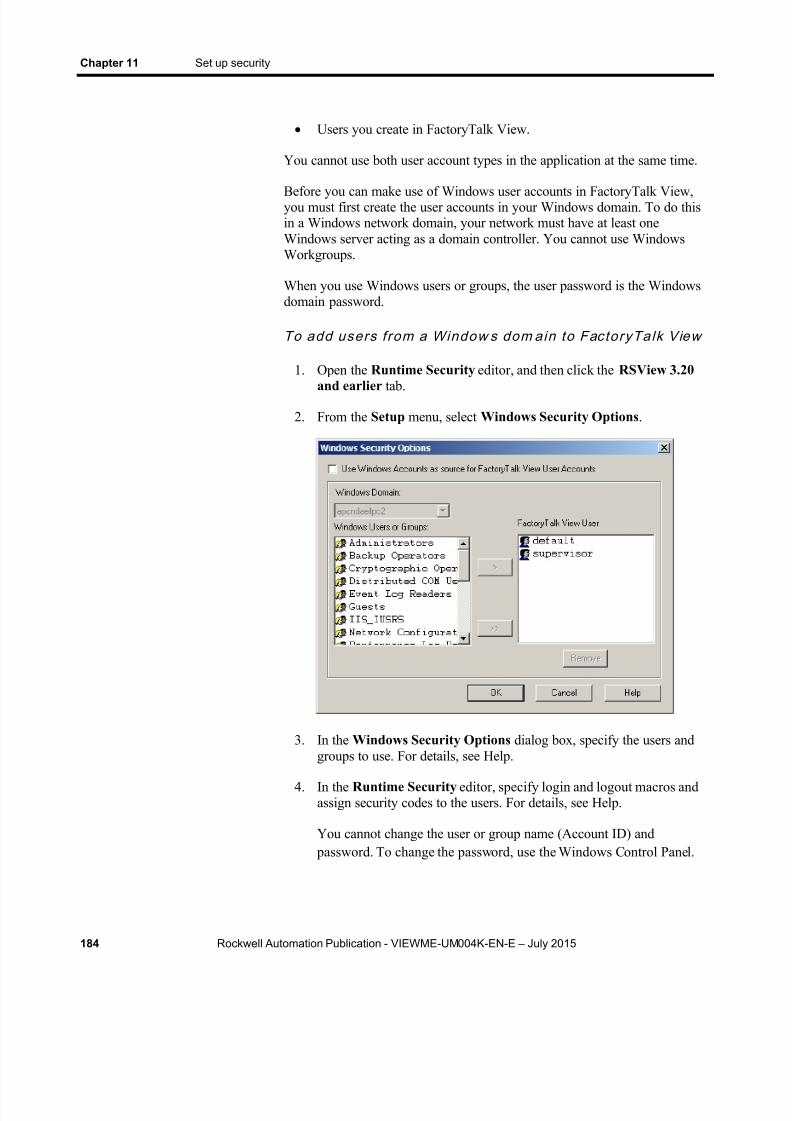
8/15/2019 Factory Talk View ME
http://slidepdf.com/reader/full/factory-talk-view-me 184/635

8/15/2019 Factory Talk View ME
http://slidepdf.com/reader/full/factory-talk-view-me 185/635
Set up security Chapter 11
Rockwell Automation Publication - VIEWME-UM004K-EN-E – July 2015 185
Remove 3.20 and earlier users or groups
You can also use the Windows Security Options dialog box to remove usersor groups. When you remove a user or group from the FactoryTalk ViewUser list, the user or group’s name is deleted from the FactoryTalk ViewRuntime Security editor. The user or group is not deleted from the Windowsdomain.
If you remove users from the Windows domain, they are not removedautomatically from the FactoryTalk View Runtime Security editor. Youmust remove the users from the Runtime Security editor manually, usingthe Windows Security Options dialog box.
Assign security to graphic displays in the Graphics editor. You can:
Assign security when you create the graphic display, or at any timeafter creating the display.
Assign the same security code to more than one display.
Assign whichever codes you want, in any order. For example, you canchoose to use only the codes D and P and you can assign P before youassign D.
For more information about graphic displays, see Use graphic displays on page 299 .
To assign security to a graphic display
1. In the Graphics editor, right-click an empty area of the display, andthen select Display Settings .
2. In the General tab, select a security code.
Assign security tographic displays

8/15/2019 Factory Talk View ME
http://slidepdf.com/reader/full/factory-talk-view-me 186/635
Chapter 11 Set up security
186 Rockwell Automation Publication - VIEWME-UM004K-EN-E – July 2015
3. To give every security code access to the display, select the asterisk(*). The * is selected by default.
Use Login and Logout buttons to provide a way for users to log in and log
out. Make sure you place these buttons in graphic displays that all users haveaccess to.
Log in
When the application starts, the DEFAULT user is logged in. If a macro isassigned to the DEFAULT user, the macro runs.
For example, you could create a macro to set the remote display number toopen a new login display after the DEFAULT user logs in. For informationabout controlling display changes remotely, see Control display changesremotely on page 114 . Remote display changes are not checked for security.
To provide a way for users to log in
1. Specify the startup display in the Startup editor, in the Initial graphic box. The startup display is the graphic display that opens when yourapplication starts running.
2. The startup display must have the * code or a security code that isassigned to the DEFAULT user, or it will not open.
For information about the Startup editor, see Create runtimeapplications on page 221 .
3. Create a Login button in the startup display.
For information about creating graphic objects, see Use graphic objects on page 331 . For information about setting up Login buttons, see Help.
For more information about logging in, see Use your application on page257 .
Log outWhen the current user logs out, if a logout macro is assigned to the user, themacro runs. If the user belongs to a group, and a logout macro is set up forthe group, the logout macro runs.
After the current user is logged out, the DEFAULT user is logged in. If alogin macro is assigned to the DEFAULT user, the macro runs.
Provide a way forusers to log in andlog out

8/15/2019 Factory Talk View ME
http://slidepdf.com/reader/full/factory-talk-view-me 187/635
Set up security Chapter 11
Rockwell Automation Publication - VIEWME-UM004K-EN-E – July 2015 187
You can also set up the application to automatically log out the current userafter a specified period of inactivity. For more information, see Log outautomatically on page 187 .
To provide a way for users to log ou t
Create a Logout button in a graphic display that all logged-in usershave access to.
Log out automatically
You can set up your runtime terminal so that the current user will be loggedout automatically after the terminal has been inactive for a specified periodof time. The automatic logout is independent of FactoryTalk Security settings
or Windows security settings. The logout will take place regardless of whatyou set up in FactoryTalk Security or Windows.
To se t up autom at ic logo ut
1. In the Explorer window, double-click Project Settings , and then clickthe Runtime tab.
2. Select Enable auto logout .
3. Specify how many minutes the terminal must be inactive before theautomatic logout occurs.
4. If desired, specify a graphic display to open after the automatic logout.
At run time, when the inactivity period expires, the current user is loggedout. Logout macros assigned to the current user run. The DEFAULT user islogged in. The DEFAULT user’s login macro runs. The specified graph icdisplay opens (if any).
Example: Assign security codes to prevent accessto graphic displays
This example shows how to set up users with access to different graphicdisplays.
1. Assign security codes to graphic displays as follows:
To this display Assign this security code
Alarm History A
Boiler B
Applicationexamples
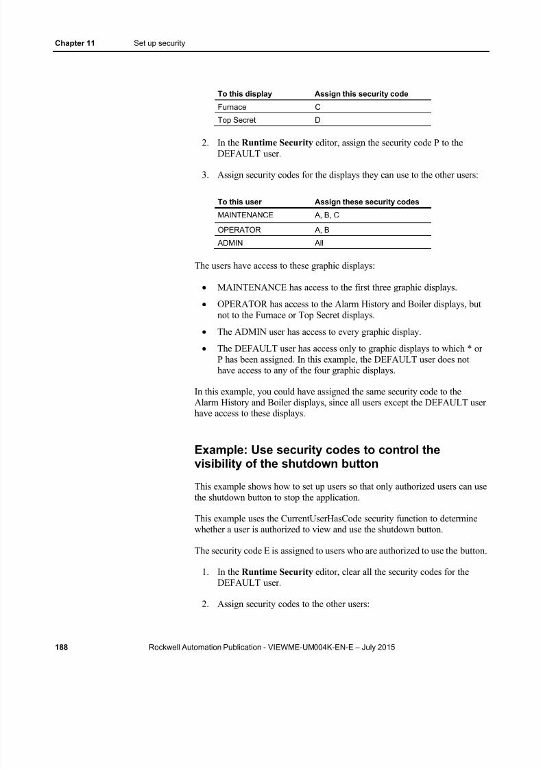
8/15/2019 Factory Talk View ME
http://slidepdf.com/reader/full/factory-talk-view-me 188/635
Chapter 11 Set up security
188 Rockwell Automation Publication - VIEWME-UM004K-EN-E – July 2015
To this display Assign this security code
Furnace C
Top Secret D
2. In the Runtime Security editor, assign the security code P to theDEFAULT user.
3. Assign security codes for the displays they can use to the other users:
To this user Assign these security codes
MAINTENANCE A, B, C
OPERATOR A, B
ADMIN All
The users have access to these graphic displays:
MAINTENANCE has access to the first three graphic displays.
OPERATOR has access to the Alarm History and Boiler displays, butnot to the Furnace or Top Secret displays.
The ADMIN user has access to every graphic display.
The DEFAULT user has access only to graphic displays to which * orP has been assigned. In this example, the DEFAULT user does nothave access to any of the four graphic displays.
In this example, you could have assigned the same security code to theAlarm History and Boiler displays, since all users except the DEFAULT userhave access to these displays.
Example: Use security codes to control thevisibility of the shutdown button
This example shows how to set up users so that only authorized users can usethe shutdown button to stop the application.
This example uses the CurrentUserHasCode security function to determinewhether a user is authorized to view and use the shutdown button.
The security code E is assigned to users who are authorized to use the button.
1. In the Runtime Security editor, clear all the security codes for theDEFAULT user.
2. Assign security codes to the other users:
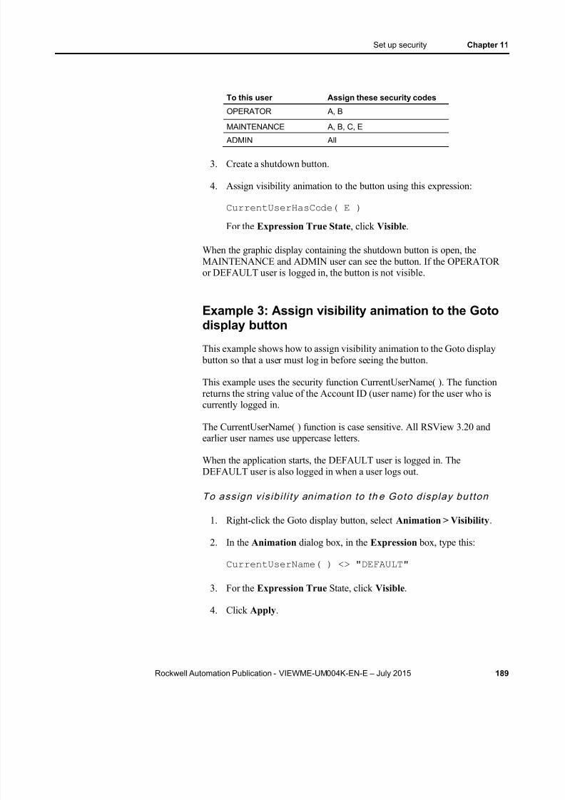
8/15/2019 Factory Talk View ME
http://slidepdf.com/reader/full/factory-talk-view-me 189/635
Set up security Chapter 11
Rockwell Automation Publication - VIEWME-UM004K-EN-E – July 2015 189
To this user Assign these security codes
OPERATOR A, B
MAINTENANCE A, B, C, E
ADMIN All
3. Create a shutdown button.
4. Assign visibility animation to the button using this expression:
CurrentUserHasCode( E )
For the Expression True State , click Visible .
When the graphic display containing the shutdown button is open, theMAINTENANCE and ADMIN user can see the button. If the OPERATOR
or DEFAULT user is logged in, the button is not visible.
Example 3: Assign visibility animation to the Gotodisplay button
This example shows how to assign visibility animation to the Goto display button so that a user must log in before seeing the button.
This example uses the security function CurrentUserName( ). The functionreturns the string value of the Account ID (user name) for the user who iscurrently logged in.
The CurrentUserName( ) function is case sensitive. All RSView 3.20 andearlier user names use uppercase letters.
When the application starts, the DEFAULT user is logged in. TheDEFAULT user is also logged in when a user logs out.
To ass ign v is ib i l i ty animat ion to th e Goto d isplay but ton
1. Right-click the Goto display button, select Animation > Visibility .
2. In the Animation dialog box, in the Expression box, type this:CurrentUserName( ) <> "DEFAULT"
3. For the Expression True State, click Visible .
4. Click Apply .

8/15/2019 Factory Talk View ME
http://slidepdf.com/reader/full/factory-talk-view-me 190/635
Chapter 11 Set up security
190 Rockwell Automation Publication - VIEWME-UM004K-EN-E – July 2015
Example 4: Assign visibility animation to theshutdown button
This example shows how to assign visibility animation to the shutdown button so that only the ADMIN user can stop the application.
To a s s ign v i s ib il i ty an ima t ion to the shu tdown bu t ton
1. Right-click the shutdown button, select Animation > Visibility .
2. In the Animation dialog box, in the Expression box, type this:
CurrentUserName( ) == “ADMIN”
3. For the Expression True State, click Visible .
4. Click Apply .
Example 5: Assign visibility animation to theshutdown button
This example shows how to assign visibility animation to the shutdown button so that only users assigned code G or code H can stop the application.
To a s s ign v i s ib il i ty an ima t ion to the shu tdow n bu t ton
1. Right-click the shutdown button, select Animation > Visibility .
2. In the Animation dialog box, in the Expression box, type this:
CurrentUserHasCode(GH)
3. For the Expression True State, click Visible .
4. Click Apply .
Example 6: Prevent unauthorized users fromstopping the application
To prevent unauthor ized users f rom s to pping th eappl ica t ion
Do not use a title bar on the application window, because the title barcontains a Close button. To turn off the title bar for the applicationwindow, in the Project Settings editor, in the Runtime tab, clear theTitle bar check box.

8/15/2019 Factory Talk View ME
http://slidepdf.com/reader/full/factory-talk-view-me 191/635
Set up security Chapter 11
Rockwell Automation Publication - VIEWME-UM004K-EN-E – July 2015 191
For more information about using the Project Settings editor, seeWork with applications on page 61 .
Assign visibility animation to the shutdown button, so that the button is
only visible when a user who is authorized to stop the application islogged in. For an example, see Example: Use security codes to controlthe visibility of the shutdown button on page 188 .
Or, set up security for the graphic display, in which the shutdown button is located, so only users who are authorized to stop theapplication can open the display.
Add i t ional s tep for personal com puters
Use the DeskLock tool to prevent users from having access to theWindows desktop. This will prevent access to operating system
functions such as restarting Windows or shutting down tasks. For moreinformation, see Use the DeskLock tool on page 245 .
Add i t ional s tep for PanelView Plus CE appl ica t ions
Hide the Windows Taskbar to make it inaccessible.
To hide the Windows Taskbar
1. From the Windows Start menu select Settings> Taskbar .
2. Clear the Always on top check box.
3. Select Auto hide .
4. When you are finished, click OK .
5. At the Command prompt or in the Run box, run Regflush.exe to saveyour changes to persistent internal flash memory. Otherwise, thechanges will be lost when you reboot.
In the Explorer window of FactoryTalk View Studio you can modifyadditional application behaviors related to security:
Specify the types of activities to track for audit purposes. Specify policies for passwords and user accounts, such as how often
passwords must be changed.
FactoryTalk View Studio Explorer window can also be used to change thefollowing security settings:
Set up access to the application.
Assign security access to action groups, policies, groups, and users.
Set up FactoryTalkSecurity for yourapplication

8/15/2019 Factory Talk View ME
http://slidepdf.com/reader/full/factory-talk-view-me 192/635
8/15/2019 Factory Talk View ME
http://slidepdf.com/reader/full/factory-talk-view-me 193/635
Set up security Chapter 11
Rockwell Automation Publication - VIEWME-UM004K-EN-E – July 2015 193
be, how often they must be changed (if ever), and whether to keep a record ofdeleted user accounts.
Note: Remember that any changes that you make to system security
policies will be included as part of the runtime application. It istherefore very strongly recommended that you do not alter thedefault settings in the Security Policy Properties dialog boxunless absolutely necessary, and unless you are aware of thefull implications of the changes. Always test the runtimeapplication to make sure the results are what you intended.
Single s ign-on
You can also use the Security Policy to turn off FactoryTalk single sign-on.If you turn this feature off, users must log into FactoryTalk each timeFactoryTalk View Studio is restarted.
To speci fy how to m anage passwo rds , user accoun ts , andFactoryTalk s ig n-on
1. In the System Policies folder, double-click Security Policy .
2. Set up options for accounts, passwords, and single sign-on. For details,see Help.
Uncommon security permissionsAlthough users can adjust the following security permissions, it is veryuncommon. Care must be taken when changing these security permissionsfrom the default settings.
Set up security access to the FactoryTalk Directory
By default, applications and the System folder inherit the security permissions assigned to the FactoryTalk Directory. This means that you onlyneed to assign permissions to user groups or users once. If desired, you canoverride the permissions that you set up at this level by assigning different
permissions to applications and to the items in the System folder.
You can assign permissions for actions related to FactoryTalk Viewapplications and tags here or at the application level. If you assign them here,they are inherited by all applications.
8/15/2019 Factory Talk View ME
http://slidepdf.com/reader/full/factory-talk-view-me 194/635
Chapter 11 Set up security
194 Rockwell Automation Publication - VIEWME-UM004K-EN-E – July 2015
To se t secur i ty permiss ion s for the FactoryTalk Direc tory
1. At the top of the tree in the Explorer window, right-click Local, andthen select Security .
2. Specify which users and groups have access to FactoryTalk Directory,and assign permissions to users and groups for the actions listed in thedialog box. For details, see Help.
Set up security access to the application
Assign FactoryTalk Security at the application level to specify which users orgroups can open the application and add, edit, and delete components. Youcan also specify which users or groups can write to tags and set up, view, andrespond to alarms.
To se t secur i ty permiss ion s for the appl ica t ion
1. Right-click the application name, and then select Security .
2. Specify which users and groups have access to the application, andassign permissions to users and groups for the actions listed in thedialog box. For details, see Help.
Set up security access to System policies, groups,and users
You can assign security access to the System folder and to all the folders inthe System folder, including policies, groups, and users. You do this byspecifying which groups and users have access to the folder, and whatactions they can perform.
To se t up secur i ty access to p ol ic ies , group s , and u sers
1. Right-click the System folder, or a folder in the System folder, andthen select Security .
2. Specify which groups and users have access to the folder, and whatactions they can perform. For details, see Help.
Set up security access to networks and devices
You can assign security access to networks and devices in general, to thedevelopment computer, and to specific devices. Set up security for networksand devices if you are using RSLinx Classic devices.

8/15/2019 Factory Talk View ME
http://slidepdf.com/reader/full/factory-talk-view-me 195/635
Set up security Chapter 11
Rockwell Automation Publication - VIEWME-UM004K-EN-E – July 2015 195
To se t up secur i ty access to ne tworks and devices
1. In the System folder, right-click Networks and Devices , thedevelopment computer workstation, or a specific device, and thenselect Security .
2. Specify which groups and users have access to the item, and whatactions they can perform. For details, see Help.

8/15/2019 Factory Talk View ME
http://slidepdf.com/reader/full/factory-talk-view-me 196/635
Chapter 11 Set up security
196 Rockwell Automation Publication - VIEWME-UM004K-EN-E – July 2015
8/15/2019 Factory Talk View ME
http://slidepdf.com/reader/full/factory-talk-view-me 197/635
Rockwell Automation Publication - VIEWME-UM004K-EN-E – July 2015 197
Chapter 12
Set up language switching
This chapter describes:
What language switching is
Summary of steps for setting up language switching
Set up Windows to support language switching
Add languages to the application
Export application text strings for translation
Translate application text
Import translated text files
Set up multiple language support for graphic libraries
The FactoryTalk View language switching feature provides the ability to setup multiple languages for an application and switch languages dynamicallyat run time. You specify an initial language for the runtime application whenyou create it, and select the languages that will be available at run time. Youcan use up to 40 languages per development application, and 20 languages
per runtime application.
When the application runs, operators can change the language using aLanguage Switch button. Set up a different Language Switch button foreach language.
With language switching you can:
Develop an application in one language, export the user-defined textstrings for the application, and then import translated strings for up to40 languages into the same application.
Export an application’s text strings in multiple languages into a singleMicrosoft Excel spreadsheet.
Import text strings in multiple languages from a Microsoft Excelspreadsheet into your application in a single operation.
Use the same application in different countries, allowing operators ineach location to view the application in their own language.
Allow operators in multilingual countries to use the language of theirchoice.
About languageswitching

8/15/2019 Factory Talk View ME
http://slidepdf.com/reader/full/factory-talk-view-me 198/635
Chapter 12 Set up language switching
198 Rockwell Automation Publication - VIEWME-UM004K-EN-E – July 2015
Import application components developed in different countries into asingle application that supports multiple languages.
The default language
For applications that use multiple languages, you can specify one of thelanguages as the default language. Any undefined text strings in the otherlanguages can be shown in the default language.
The default language is also used for RSView Machine Edition 4.00applications. When you open or import the application into FactoryTalkView 5.00 or later, the application’s alarm, information, and local messagesare associated with the language that you select to be the default language.For example, if you open an RSView Machine Edition 4.00 application thatcontains local messages, and you select French for the default language, thelocal messages will be treated as if they are French when you export theapplication’s strings for translation. That is, they will appear in the Frenchlanguage column. You can add other languages for these messages, asdescribed in this chapter.
When you create a new application, the language you specify for theapplication is the default language. You can change the default language atany time. The default language can be any of the languages in theapplication.
You can show undefined strings in the default language during applicationdevelopment. If you do not select this option, undefined strings are shown asa question mark "?" character. If you select this option, but do not include thedefault language with the runtime application, undefined strings are shown asa question mark "?" character at run time.
Alarm trigger labels are shown in the Trigger Label Selector list using thedefault language. If you change the default language, you must re-specify thetrigger labels for every graphic object that filters alarms. To do this, specifythe trigger label names in the new default language. For more informationabout filtering alarms when your application uses multiple languages, seeFilter alarm triggers in multiple languages on page 123 .

8/15/2019 Factory Talk View ME
http://slidepdf.com/reader/full/factory-talk-view-me 199/635
Set up language switching Chapter 12
Rockwell Automation Publication - VIEWME-UM004K-EN-E – July 2015 199
To chang e the defaul t language
1. From the Tools menu, select Languages .
2. Select the language to use for the default language.
3. Click Set As Default . A large check mark to the left of the selectedlanguage indicates that it is now the default language.
4. To use this language for all undefined strings in the application, selectDisplay undefined strings using the default language .
Follow these steps to set up language switching for an application:
1. For applications that will run on a personal computer, install theWindows languages that the application will use.
2. For applications that will run on a PanelView Plus or PanelView PlusCE terminal, set up the fonts that the application will use.
3. Create, open, or import the application in the language of your choice.For details, see Work with applications on page 61 .
4. Add languages to the application. For details, see Add languages to theapplication on page 201 .
5. Create graphic objects and specify the text strings that they will use.
6. Create alarm, information, and local messages.
7. Create a Language Switch button for each language you plan to use atrun time. For details, see Help.
8. Export the application text strings for translation. For details, seeExport application text strings for translation on page 202 .
Steps for setting uplanguage switching
8/15/2019 Factory Talk View ME
http://slidepdf.com/reader/full/factory-talk-view-me 200/635
Chapter 12 Set up language switching
200 Rockwell Automation Publication - VIEWME-UM004K-EN-E – July 2015
9. Translate the text strings. For details, see Translate application text inUnicode files on page 205 .
10. Import translated text strings for each of the translation languages. For
details, see Import text on page 209 .
11. Open the application in each language, to check the layout of thetranslated text.
12. Create the runtime application, specifying the startup language and thelanguages that the operator can switch to. For details, see Createruntime applications on page 221 .
Install Windows languages
We recommend that you install all the languages that your application willuse, on both the development and runtime computers. Installing languagesturns on the Windows font support features, which allow applications toshow characters for different languages using a single application font.
For details about installing languages, see Windows Help.
PanelView Plus 7, PanelView Plus 6, PanelView Plus, PanelView PlusCompact, and PanelView Plus CE terminals are shipped with languagesalready installed.
Set up Windows fonts
For applications that will run on a PanelView Plus 7, PanelView Plus 6,PanelView Plus, PanelView Plus Compact, or PanelView Plus CE terminal,install the fonts that the application will use. For applications that will run ona personal computer, the fonts you want are generally installed when youinstall the languages for the application. Be aware that using MS ArialUnicode as the default font provides better performance for languageswitching.
For details about choosing fonts that work well with language switching, seeChoose fonts for language switching on page 343 .
Make sure that the development and runtime computers are set up to use thefonts you want for the title bar and inactive title bar. Specify the font in theWindows Control Panel, in the Display Properties dialog box.
For information about setting up fonts on a PanelView Plus 7, PanelViewPlus 6, PanelView Plus, PanelView Plus Compact, or PanelView Plus CEterminal, see the PanelView Plus Terminals User Manual .
Set up Windows forlanguage switching

8/15/2019 Factory Talk View ME
http://slidepdf.com/reader/full/factory-talk-view-me 201/635
Set up language switching Chapter 12
Rockwell Automation Publication - VIEWME-UM004K-EN-E – July 2015 201
Windows locale settings
Windows locale formatting determines how the application shows time, date,and floating point values at design time and run time.
When the application language is switched, the locale settings for the newlanguage are used even if that language has not been installed.
You do not need to edit the default locale settings.
Use the Language Configuration dialog box in FactoryTalk View Studio toadd up to 40 languages to the application.
Add languages before you:
Create Language Switch buttons.
Create the runtime application.
To add languages to an application
1. From the Tools menu, select Languages .
2. Add languages. For details, see Help.
Remove languages
You can also use the Language Configuration dialog box to removelanguages. When you remove a language, all the strings for the language aredeleted the next time you save the application. Save a component deletesstrings for the removed language from the component.
Add languages tothe application

8/15/2019 Factory Talk View ME
http://slidepdf.com/reader/full/factory-talk-view-me 202/635
Chapter 12 Set up language switching
202 Rockwell Automation Publication - VIEWME-UM004K-EN-E – July 2015
There are two options for exporting text strings:
One language at a time, saving the text in a tab-delimited text file inUnicode format. The file can be translated and then imported back into
the application. All languages at once, exporting into a single Microsoft Excel
spreadsheet. The strings in the spreadsheet can be translated and thenimported back into the application.
These text strings allow language switching and are exported for translation:
Display titles for On Top displays (defined in the Display Settings dialog box)
Text graphic objects
Captions that you define for graphic objects, including objects inglobal object displays
Alarm, local, and information messages
Alarm trigger labels
Embedded time, date, and numeric variables
Undefined strings are exported as undefined strings, regardless of whetheryou select the option in the Language Configuration dialog box to showundefined strings using the default language. That option is used only forshowing strings during application development and at run time. It does notsubstitute the default language’s strings for undefined strings in the exported
file or spreadsheet.
Export text in Unicode format
When you export text in Unicode format, these text strings are also exported:
Text descriptions and error messages for the Change Passwordwindow. These strings are exported if you use a password button inyour application.
You can translate these strings, but you cannot change their languagedynamically at run time the way you can for graphic object strings.
For the Change Password window, the runtime application will use thestrings that are in the application when the runtime application is created. Forexample, if the current application language is French, and you haveimported French text strings for the Change Password window, then theFrench strings will be compiled in the runtime application. If the operatoropens the window, the strings will be shown in French. If the operatorchanges to another language, the strings will still be shown in French.
Export applicationtext strings fortranslation
8/15/2019 Factory Talk View ME
http://slidepdf.com/reader/full/factory-talk-view-me 203/635
Set up language switching Chapter 12
Rockwell Automation Publication - VIEWME-UM004K-EN-E – July 2015 203
Unicode f i le name format
The format for the exported Unicode text file name is< ApplicationName >< HMIServerName >< RFC1766 >.txt, where:
< ApplicationName > is the name of the application.
< HMIServerName > is the name of the HMI server containing the textstrings you exported. This is always the same name as the applicationname.
< RFC1766 > is the RFC1766 name associated with the languageselected for the export operation.
For details about the schema of exported Unicode text files, see File schema on page 207 .
For a list of Windows languages and the corresponding RFC1766 names, seeMapping languages to RFC1766 names on page 601 .
Export text to a Microsoft Excel spreadsheet
FactoryTalk View supports Microsoft Excel versions 2000, 2002, 2003,2007, 2010, and 2013. The exported file is in Microsoft Excel 5.0/95Workbook format, with the extension .xls.
The maximum number of characters viewable in an Excel cell depends onthe version of Excel and the font size. If the maximum is exceeded, the cellwill be blank.
Opt imiz ing dupl ica te s t r ings
When you export text to an Excel spreadsheet, you have the option ofoptimizing duplicate strings. FactoryTalk View analyzes the text andindicates repeated instances of the same string using a reference number.This way the translator only needs to translate the text once. When youimport the translated strings from the spreadsheet into the application,FactoryTalk View copies the translated string into all the graphic objects thatused the string originally.
Excel spreadsheet file name format
The format for the exported spreadsheet file name is< ApplicationName >_< ExportVersion >.xls, where:
< ApplicationName > is the name of the application.
8/15/2019 Factory Talk View ME
http://slidepdf.com/reader/full/factory-talk-view-me 204/635
Chapter 12 Set up language switching
204 Rockwell Automation Publication - VIEWME-UM004K-EN-E – July 2015
< ExportVersion > is an incremental number assigned to each successfulexport operation.
For details about the schema of exported spreadsheet files, see Translate
application text in Excel spreadsheet files on page 205 .
For a list of Windows languages and the corresponding RFC1766 names, seeMapping languages to RFC1766 names on page 601 .
Exported language string file locations
Exported language files are saved at this default location:
(Windows XP) C:\Documents and Settings\All Users\SharedDocuments\RSView Enterprise\Strings
(Windows Server 2012, Windows 8.1, Windows 8, Windows 7, andWindows Server 2008) C:\Users\Public\Public Documents\RSViewEnterprise\Strings
You can specify another location if desired.
To expor t appl ica t ion text
1. From the Tools menu, select Languages .
2. In the Language Configuration dialog box, select the application
language for which to export text strings.
If you are going to export strings for all languages defined for theapplication, it does not matter which language is selected in theLanguage Configuration dialog box.
3. Click Export .
4. Follow the instructions in the String Import Export Wizard.
For details about options in the String Import Export wizard, clickHelp .
If you export to a Unicode text file multiple times to the same location, previously exported versions are overwritten.
Problems exporting
You do not have to check every text file created during an export to verifythat text strings were exported correctly. If errors occur, or if you cancel the
8/15/2019 Factory Talk View ME
http://slidepdf.com/reader/full/factory-talk-view-me 205/635
Set up language switching Chapter 12
Rockwell Automation Publication - VIEWME-UM004K-EN-E – July 2015 205
export while it is in progress, a message appears in the Diagnostics List , andin the FactoryTalk Diagnostics log file.
In addition, errors are shown when they occur in a log file called
ExportErrors.txt, which is saved at this location:
(Windows XP) C:\Documents and Settings\All Users\SharedDocuments\RSView Enterprise\Strings
(Windows Server 2012, Windows 8.1, Windows 8, Windows 7, andWindows Server 2008) C:\Users\Public\Public Documents\RSViewEnterprise\Strings
Existing error log files are overwritten for each subsequent export operationthat generates errors.
This section contains information about the format and schema of theexported Microsoft Excel spreadsheet file.
The spreadsheet contains a header row followed by a row for each text stringin the application. There is a column for each language defined in theapplication. The default language is first, followed by the remaininglanguages in alphabetical order by RFC1766 name. All cells use the textformat.
Do not delete the header row in the spreadsheet. FactoryTalk View requiresthis information when you import the translated text into your application.Similarly, do not change the cell formats.
If you select the option to optimize duplicate strings, there is a referencecolumn to the left of each language column. Do not change the informationin the reference columns.
This section contains information about the format and schema of theexported Unicode text file. It also contains information about usingMicrosoft Excel or Windows Notepad to edit the file.
Because FactoryTalk View requires that parts of the text file remain the waythey were exported, give the information in this section to the translator, toensure that the file can be imported after it has been modified.
File name and format
You will likely want to rename the file before translating it, to avoidconfusing it with the original file. You can use any file name ending with thefile extension .txt.
To import text into a FactoryTalk View application, you must save the file astab-delimited text, in Unicode text format.
Translateapplication text inExcel spreadsheetfiles
Translateapplication text inUnicode files
8/15/2019 Factory Talk View ME
http://slidepdf.com/reader/full/factory-talk-view-me 206/635
Chapter 12 Set up language switching
206 Rockwell Automation Publication - VIEWME-UM004K-EN-E – July 2015
Open the text file in Microsoft Excel
When you open the text file in Microsoft Excel, the Text Import Wizardappears.
To spec ify the f i le format (Step 1 of the wizard)
1. Click Delimited .
2. In the Start import at row box, type or select 1.
3. In the File origin list, click Windows (ANSI) .
4. Click Next .
To sp ecify the f ield d elimiter (Step 2 of t he wizard)
1. Select the Tab check box. If any other check boxes are selected, clearthem.
2. Make sure the Treat consecutive delimiters as one check box iscleared.
3. Click Next .
To speci fy th e colum n d ata format (Step 3 of th e wizard)
1. If it is not selected already, under Column data format , clickGeneral .
2. Click Finish .
Save the text file in Microsoft Excel
To save the f i le
1. From the File menu, select Save .
2. Excel warns that the file may contain features that are not compatiblewith Unicode text.
3. When prompted to keep the workbook in Unicode format that leavesout incompatible features, click Yes .
4. Close the file.
5. When prompted to save changes, click Yes .
8/15/2019 Factory Talk View ME
http://slidepdf.com/reader/full/factory-talk-view-me 207/635
Set up language switching Chapter 12
Rockwell Automation Publication - VIEWME-UM004K-EN-E – July 2015 207
6. When prompted again to keep the workbook in Unicode format thatleaves out incompatible features, click Yes .
Differences in file format for files saved in Excel
If you use Notepad to open a Unicode text file that was saved in Excel, youwill notice some differences from a file edited and saved in Notepad.
You do not have to change the format of the file before you import it intoFactoryTalk View.
The differences are:
Double quotes surrounding the string definitions are removed for moststrings.
String definitions containing embedded double quotes or othercharacters that Excel treats as special characters, such as commas, areenclosed within double quotes.
Any embedded double quotes are converted to a pair of double quotes.
Save the Unicode text file in Notepad
When saving the file, save it using the Unicode encoding option in the SaveAs dialog box.
File schema
Comment s
The text file uses the # symbol as a comment delimiter if it is the firstcharacter on a line.
Header
The first seven lines of the text file contain header information that must not be translated or modified.
B o d y
The body of the text file starts on line eight, and includes the followingcolumns:
8/15/2019 Factory Talk View ME
http://slidepdf.com/reader/full/factory-talk-view-me 208/635
8/15/2019 Factory Talk View ME
http://slidepdf.com/reader/full/factory-talk-view-me 209/635
Set up language switching Chapter 12
Rockwell Automation Publication - VIEWME-UM004K-EN-E – July 2015 209
appears in the application as:
Call Duty Manager
Work with backslashes and new line characters
To force text to begin on a new line, precede the text with the characters \n .For example:
Motor\nStopped
appears in the application as:
Motor
Stopped
To make the characters \n appear as part of the text, type \\n. To make a backslash appear in the application, type two backslashes ( \\).
Imp or t tex t conta in ing mu l t ip le backs lashes
If the imported text file contains an odd number of backslashes next to eachother, one of the backslashes will be ignored.
For example, the string:
Seven\\\Eight
is imported into the application as:
Seven\Eight
You can import text strings saved in Unicode text format or in MicrosoftExcel spreadsheet format.
If your text strings are in Microsoft Excel spreadsheet format, only textstrings that exist in the spreadsheet are imported. This means that existingstrings in the application are not deleted during the import if they are not in
the spreadsheet.
Back up the text in your application before importing. You can do this byexporting the text.
Save the backup file in a different location than the translated file you areabout to import.
Import text

8/15/2019 Factory Talk View ME
http://slidepdf.com/reader/full/factory-talk-view-me 210/635
Chapter 12 Set up language switching
210 Rockwell Automation Publication - VIEWME-UM004K-EN-E – July 2015
To import text into your application from a text file
1. From the Tools menu, select Languages .
2. In the Language Configuration dialog box, select the applicationlanguage for which to import text strings.
If you are going to import strings for multiple languages defined in anExcel spreadsheet, it does not matter which language is selected in theLanguage Configuration dialog box.
3. Click Import .
4. Follow the instructions in the String Import Export Wizard.
For details about options in the String Import Export wizard, clickHelp .
If you cancel the import before it is complete, any text strings that werechanged are not restored to their original values. To restore the text that wasoriginally in the application, import the text from the backup file you created.
You do not have to check every graphic display in your application to verifythat text was imported correctly. If errors occurred while importing text, theyare shown automatically from a log file called ImportErrors.txt in thefollowing folder:
(Windows XP) C:\Documents and Settings\All Users\SharedDocuments\RSView Enterprise\Strings
(Windows Server 2012, Windows 8.1, Windows 8, Windows 7, andWindows Server 2008) C:\Users\Public\Public Documents\RSViewEnterprise\Strings
Each time errors occur while importing text into an application, theImportErrors.txt file is overwritten.
If errors occurred while importing text, or if the import was canceled, amessage appears in the Diagnostics List , and in the FactoryTalk Diagnosticslog file.
Cancel importing
If some, but not all, of the text in an application seems to have beenmodified, the import might have been canceled. If you cancel the import
before it is complete, any text strings that were changed are not restored totheir original values. To restore the text originally in the application, importthe text from the backup text file you created before importing.
Problems importing
8/15/2019 Factory Talk View ME
http://slidepdf.com/reader/full/factory-talk-view-me 211/635
Set up language switching Chapter 12
Rockwell Automation Publication - VIEWME-UM004K-EN-E – July 2015 211
When you create an application, the graphic libraries installed withFactoryTalk View are "language neutral" by default.
This means that graphic objects in the libraries always show their text strings
as shipped, regardless of the current application language. Since the currentapplication language is ignored, text strings never appear as undefined.
You can change the default for any graphic library, so that it supportsmultiple languages instead of a single language. When you do this, when youopen the library you can view the text strings that are defined for the currentapplication language. If the library’s text strings have not been defined forthe current language, the undefined strings appear as single question marks.
If you turn off a graphic library’s multiple language support, and then savethe library, only strings for the current application language are saved. Thecurrent application language therefore becomes the "language neutral"
language. Any strings for other languages are deleted.
To turn on support for multiple languages in agraphic library
1. Right-click an empty area in the graphic library display, and then selectDisplay Settings.
2. In the General tab, select Support Multiple Languages .
After you turn on support for multiple languages, when you save the graphiclibrary, all strings that support language switching are saved in the currentapplication language. For information about saving libraries in multiplelanguages, see Use libraries to store displays with multiple languages on
page 316 .
Use graphic libraries that support multiplelanguages
To use the graphics libraries in an application, you can add a graphic libraryinto the Displays folder or copy objects from a graphic library into a graphic
display. If the graphic library supports multiple languages:
When you add the graphic library into the Displays folder, all strings,including strings for languages that are not supported by theapplication, are included with the display.
If you copy an object from the graphic library into a graphic display,only strings for languages supported by the application are copied.
For more information about using graphic libraries, see Use graphic displays on page 299 .
Set up multiplelanguage supportfor graphic libraries

8/15/2019 Factory Talk View ME
http://slidepdf.com/reader/full/factory-talk-view-me 212/635
Chapter 12 Set up language switching
212 Rockwell Automation Publication - VIEWME-UM004K-EN-E – July 2015
8/15/2019 Factory Talk View ME
http://slidepdf.com/reader/full/factory-talk-view-me 213/635
Rockwell Automation Publication - VIEWME-UM004K-EN-E – July 2015 213
Chapter 13
Set up display navigation
This chapter describes:
What display navigation is
Develop a hierarchy of displays
Test display navigation
Use graphic objects to navigate
Control display changes remotely
This chapter describes methods for navigating between graphic displays. Forinformation about navigating between objects in a graphic display, see Usethe keyboard to navigate to and select objects on page 395 .
The term display navigation refers to the way the operator moves betweenthe graphic displays that make up an application.
Use these methods to set up display navigation for your application:
Develop a hierarchy of graphic displays, to chart how users willnavigate the application.
Determine which users will have access to which parts of theapplication.
Create graphic objects that the operator can use to navigate theapplication.
Use the Remote Display Number connection to automatically controldisplay changes. The use of this connection is optional. Assign it in theGlobal Connections editor.
In the Startup editor, specify the graphic display to open when theapplication starts.
Set up security so that only authorized users have access to theapplication or parts of the application.
For information about setting up security, see Set up security on page 175 .
About displaynavigation

8/15/2019 Factory Talk View ME
http://slidepdf.com/reader/full/factory-talk-view-me 214/635
8/15/2019 Factory Talk View ME
http://slidepdf.com/reader/full/factory-talk-view-me 215/635
Set up display navigation Chapter 13
Rockwell Automation Publication - VIEWME-UM004K-EN-E – July 2015 215
Once you set up display navigation for your application, test the applicationto make sure that navigation flows smoothly and that you have avoided
problems like these:
A graphic display contains no buttons for moving forward or back. When a graphic display closes, no other display is open and there is no
way to continue using the application.
For information about testing your application, see Test your application on page 221 .
Use these graphic objects to navigate through the displays in the application:
Use this object To do this
Goto display button Open the specified graphic display.
Goto configure modebutton
Stop the application and open the FactoryTalk® ViewME Station dialog box.
Return to display button Close the current display and open the previousdisplay.
Close display button Close the current display. Can send a value to a tagwhen the display closes.
Display list selector Provide a list of graphic displays so the operator canselect which display to open.
Shutdown button Stop the application and exit FactoryTalk® View MEStation.
The behavior of these graphic objects depends on which types of graphicdisplays are used. See the following sections for details.
For detailed information about setting up graphic objects, see Help.
Switch languages
If the application uses multiple languages and operators will be switchinglanguages at run time, place Language Switch buttons in a display that theoperators have access to. For example, put the buttons in the display thatopens when the operators log in. Create a Language Switch button for eachlanguage that the operators will be using.
For more information about setting up multiple languages, see Set uplanguage switching on page 197 .
Test displaynavigation
Use graphic objectsto navigate
8/15/2019 Factory Talk View ME
http://slidepdf.com/reader/full/factory-talk-view-me 216/635
Chapter 13 Set up display navigation
216 Rockwell Automation Publication - VIEWME-UM004K-EN-E – July 2015
Display type
The display type you use gives you additional control over how the operatornavigates between displays. For example, use the On Top type to keep agraphic display on top at all times, even when another display has focus. Oruse the Replace type if you want a display to replace all other open displayswhen it opens.
For more information about display types, see About display types on page310 .
Goto display buttons
When you set up a Goto display button, specify the graphic display to open
when the operator presses the button at run time.The specified display does not open if the operator does not have securityaccess for the display.
You can also assign a parameter file or parameter list that assigns tags to tag placeholders in the display when the display opens. For more informationabout parameter files and lists, see Use parameters and global objects on
page 501 .
For information about setting up Goto display buttons, see Help.
How display types affect the button’s behavior
The Goto display button’s behavior at run time also depends on which typesof graphic displays are already open and which type of display it is opening:
If the graphic display assigned to the button is a Replace display, itcloses any open On Top or Replace displays. It does not close any OnTop displays that use the Cannot Be Replaced option.
If the display assigned to the button is already open, but does not havefocus, pressing the button gives the display focus.
The operator cannot use the Goto display button to open Replace displays if
display change is currently controlled remotely (using global connections).But the operator can still open On Top displays.
Goto configure mode buttons
When the operator presses a goto configure mode button at run time, thecurrent application stops running and the FactoryTalk View ME Station dialog box opens.

8/15/2019 Factory Talk View ME
http://slidepdf.com/reader/full/factory-talk-view-me 217/635
Set up display navigation Chapter 13
Rockwell Automation Publication - VIEWME-UM004K-EN-E – July 2015 217
While in configure mode, the operator can use FactoryTalk View ME Stationto change applications, application settings, and terminal settings. Theoperator can also delete log files. For more information about theFactoryTalk View ME Station dialog box, see Run applications on a
personal computer on page 229 .
Return to display buttons
When the operator presses a return to display button at run time, the graphicdisplay that the button is on closes and the display that was previously openreopens.
The current display does not close if:
The display change is currently controlled remotely (using globalconnections).
There were no previously opened Replace displays.
The operator does not have security access for the previous display.This can only occur if a new user logs in using a login button in thecurrent display.
The return to display button only goes back to the most recent display. Itdoes not go back through a series of displays.
For information about setting up return to display buttons, see Help.
How display types affect the button’s behavior
Both the current display and the previous display must be Replace displays.When the operator presses the return to display button:
If the graphic display that is closing is a Replace display, the displaycloses and the previously opened Replace display opens. Any On Topdisplays that were previously open with the Replace display are notreopened.
If the graphic display that is closing is an On Top display, the displaycloses but no display is reopened.
We therefore recommend that you use return to display buttons in Replacedisplays only.
Example: Navigating through displays
This example uses the display hierarchy illustrated in Develop a hierarchy ofdisplays on page 214 , and shows what happens as the operator navigatesthrough the hierarchy. The graphic displays are all Replace displays.
8/15/2019 Factory Talk View ME
http://slidepdf.com/reader/full/factory-talk-view-me 218/635
Chapter 13 Set up display navigation
218 Rockwell Automation Publication - VIEWME-UM004K-EN-E – July 2015
1. In the Main Menu display, the operator uses a display list selector toopen the Process Overview display.
2. In the Process Overview display, the operator presses a Goto display
button to open the Process Monitoring 1 display.
3. After viewing the state of the process, the operator presses a return todisplay button to close the current display and reopen the ProcessOverview display.
4. In the Process Overview display, the operator presses a return todisplay button. Which display opens? The Process Monitoring 1display (because this was the previously opened display).
To return to the Main Menu display from the Process Overviewdisplay, the operator would have to press a Goto display button that is
set up to open the Main Menu display.
Close display buttons
When the operator presses a close display button at run time, the graphicdisplay that the button is on closes. You can set up the button to write out avalue when the display closes.
If the graphic display that is closing is a Replace display, and the displaychange is controlled remotely, the display does not close. If the display doesnot close, the close value, if any, is not written out.
If the display change is controlled by the operator and the graphic displaythat is closing is a Replace display, if there are no On Top displays open, anempty window is shown. The operator will not be able to use the applicationagain (unless a remote display change occurs or an alarm, activity, orinformation message display opens).
We therefore recommend that you use close display buttons in On Topdisplays only.
For information about setting up close display buttons, see Help.
Display list selectors
Use the display list selector to show a list of graphic displays that theoperator can choose from. The operator can scroll through the list and selectthe graphic display to open.
The specified display does not open if the operator does not have securityaccess for the display.
8/15/2019 Factory Talk View ME
http://slidepdf.com/reader/full/factory-talk-view-me 219/635
Set up display navigation Chapter 13
Rockwell Automation Publication - VIEWME-UM004K-EN-E – July 2015 219
You can also assign a parameter file or parameter list that assigns tags to tag placeholders in the display when the display opens. For more informationabout parameter files and lists, see Use parameters and global objects on
page 501 .
For information about setting up display list selectors, see Help.
How display types affect the selector’s behavior
The display list selector’ s behavior at run time also depends on which typesof graphic displays are already open and which type of display it is opening:
If the selected graphic display is a Replace display, it closes any openOn Top and Replace displays. It does not close On Top displays thatuse the Cannot Be Replaced option.
If the selected display is an On Top display, it opens on top of thecurrent display. The current display does not close.
The operator cannot use the display list selector to open Replace displays ifdisplay change is currently controlled remotely. But the operator can stillopen On Top displays (with or without the Cannot Be Replaced option).
Selec t the d isplay to o pen
The operator can scroll through the list and select displays using the key button graphic objects, or, if the list has the input focus, by using the arrowkeys and Enter key on a keypad or external keyboard.
You can link key buttons to a specific display list selector, or set up the buttons to work with whichever object is selected in the graphic display.
For information about input focus, see What input focus looks like on page395 . For information about linking buttons to the display list selector, seeLink buttons to objects on page 397 .
Shutdown buttons
When the operator presses the shutdown button at run time, the applicationstops and FactoryTalk View ME Station closes.
To prevent an unauthorized user from stopping the application, assignvisibility animation to the shutdown button. For details, see Applicationexamples on page 187 . Or, place the button in a display that only authorizedusers have access to.
For information about setting up shutdown buttons, see Help.

8/15/2019 Factory Talk View ME
http://slidepdf.com/reader/full/factory-talk-view-me 220/635
Chapter 13 Set up display navigation
220 Rockwell Automation Publication - VIEWME-UM004K-EN-E – July 2015
To control display changes remotely, you can set up the data source to opengraphic displays using global connections.
Global connections are connections that apply to your entire runtime
application. Global connections allow the data source to control or interactwith your application at run time.
For example, the Remote Display Number connection is a globalconnection that you can use to control display changes from the data source.You can also use global connections to apply parameters to the displays thatare opened from the data source, to close one or more On Top displays fromthe data source, to print graphic displays from the data source, to run macrosfrom the data source, to control the date and time displayed on the runtimeterminal, to set the intensity of PanelView backlights, and to monitor runtimeRAM usage. For more information about global connections, see Set upglobal connections on page 111 .
Control displaychanges remotely

8/15/2019 Factory Talk View ME
http://slidepdf.com/reader/full/factory-talk-view-me 221/635
Rockwell Automation Publication - VIEWME-UM004K-EN-E – July 2015 221
Chapter 14
Create runtime applications
This chapter describes:
Specify startup settings
Test your application
Create runtime application files
Convert runtime application files to development applications
Use the Startup editor to specify which application processes andcomponents to start when the application starts at run time.
You can specify startup settings once you have set up all the parts of theapplication, or you can specify processes and select components in theStartup editor as you create them.
For detailed information about the options in the Startup editor, see Help.
You can test your application in FactoryTalk View Studio at any time duringthe development process, to make sure that everything works the way youintend.
Specify startupsettings
Test yourapplication
8/15/2019 Factory Talk View ME
http://slidepdf.com/reader/full/factory-talk-view-me 222/635
Chapter 14 Create runtime applications
222 Rockwell Automation Publication - VIEWME-UM004K-EN-E – July 2015
If the development computer is connected to the data source, you can test allfunctions of the application, including security settings, language switching,communications, and alarm monitoring.
A FactoryTalk View ME Station emulator opens on the developmentcomputer and runs the application. This runtime version of the application isa temporary version for testing use only. You cannot run it on anothercomputer.
There is a two-hour time limit for test running the application in FactoryTalkView Studio.
The procedure in this section shows you how to test your entire application.For information about testing a single graphic display, see Test your displaysas you work on page 308 .
To test your application in FactoryTalk View Studio
1. On the Application menu, click T est Application , or click the Test
Application tool .
2. If your application uses multiple languages, specify the languages toinclude and the initial runtime language, and then press Finish. Fordetails, see Help.
3. Test your application.
4. To stop your application, press a shutdown button, or type thecharacter ‘x.’
Make sure you provide the operator with a method for shutting downthe application at run time. For more information about methods forshutting down applications, see Shut down applications on page 234 .
Once you have tested your application to make sure everything works theway you intend, create the runtime application file and transfer the file to theruntime computer.
Before you can run your application, you must create a runtime version.When you create the runtime version, FactoryTalk View Studio compiles allof the necessary application information into a single file with the extension.mer.
Create .mer files for previous versions
You can specify the version of FactoryTalk View ME Station for which tocreate the .mer file. For example, if the application will run on a terminal that
Create runtimeapplication files

8/15/2019 Factory Talk View ME
http://slidepdf.com/reader/full/factory-talk-view-me 223/635

8/15/2019 Factory Talk View ME
http://slidepdf.com/reader/full/factory-talk-view-me 224/635

8/15/2019 Factory Talk View ME
http://slidepdf.com/reader/full/factory-talk-view-me 225/635

8/15/2019 Factory Talk View ME
http://slidepdf.com/reader/full/factory-talk-view-me 226/635
Chapter 14 Create runtime applications
226 Rockwell Automation Publication - VIEWME-UM004K-EN-E – July 2015
For FactoryTalk View version 5.00 and later .mer files, you can convert theruntime application file back to a development application. This allows youto make changes to the application without losing runtime information suchas passwords and RecipePlus data.
To convert the runtime application file, use the Restore runtime applicationoperation in the Application Manager. Data logging and alarm data thatoccurred at run time are not restored to the development application.
RSLinx Enterprise device shortcuts that were edited at run time are restoredwhen you convert the runtime application to a development application.However, the Runtime tab in the RSLinx Enterprise CommunicationSetup editor might not show the device configuration for the runtimeapplication. Make sure the Runtime tab shows the correct deviceconfiguration before making any changes to the shortcuts.
Note: RSLinx Enterprise device shortcuts that were valid on theruntime terminal might not exist or might be invalid on thedevelopment computer. Review all device and tag file shortcutassignments in the RSLinx Enterprise Communication Setupeditor before you edit, test, or transfer the application.
To convert a runtime application to a developmentapplication
1. In FactoryTalk View Studio, from the Tools menu, select ApplicationManager.
2. When prompted to select the application type, select Machine Edition ,and then click Next .
3. Click Restore runtime application , and then click Next .
4. Specify the folder and file name of the runtime application to convert.
Convert runtimeapplication files todevelopmentapplications

8/15/2019 Factory Talk View ME
http://slidepdf.com/reader/full/factory-talk-view-me 227/635
Create runtime applications Chapter 14
Rockwell Automation Publication - VIEWME-UM004K-EN-E – July 2015 227
5. If you created a password for the file when you created the runtimeapplication, type the password.
6. Click Next .
7. Type a name for the converted application, and then click Finish .

8/15/2019 Factory Talk View ME
http://slidepdf.com/reader/full/factory-talk-view-me 228/635
Chapter 14 Create runtime applications
228 Rockwell Automation Publication - VIEWME-UM004K-EN-E – July 2015
8/15/2019 Factory Talk View ME
http://slidepdf.com/reader/full/factory-talk-view-me 229/635
Rockwell Automation Publication - VIEWME-UM004K-EN-E – July 2015 229
Chapter 15
Run applications on a personalcomputer
This chapter describes:
Move applications to the runtime computer
Start FactoryTalk View ME Station
Load and run applications
Shut down applications
Edit device short cuts
Look up contact information for technical support
Set up FactoryTalk Diagnostics at run time
Set up serial ports for KEPServer Enterprise
Set up RSLinx Enterprise communication drivers
Specify the printers to use at run time
Specify startup options for FactoryTalk View ME Station Delete log files on the runtime computer
Specify the time, date, and number formats to use at run time
Use the DeskLock tool
Follow these steps to:
Install hardware and software on a PanelView Plus 7, PanelView Plus6, PanelView Plus, PanelView Plus Compact, or PanelView Plus CEterminal.
Transfer your application to the PanelView Plus 7, PanelView Plus 6,PanelView Plus, PanelView Plus Compact, or PanelView Plus CEterminal.
For information about installing FactoryTalk View ME Station, see the FactoryTalk View Machine Edition Installation Guide .
Steps fortransferringapplications to aPanelView Plus
terminal
8/15/2019 Factory Talk View ME
http://slidepdf.com/reader/full/factory-talk-view-me 230/635
Chapter 15 Run applications on a personal computer
230 Rockwell Automation Publication - VIEWME-UM004K-EN-E – July 2015
Install hardware and software on the runtimecomputer
1. If you will be printing displays, alarms, or diagnostics messages, set up printer connections on the runtime computer.
For more information, see Specify the printers to use at run time on page 238 .
2. If you are using RSLinx Enterprise, set up communications asdescribed in Set up communications on page 79 .
3. If you are using RSLinx Classic as the OPC server on the runtimecomputer, install RSLinx Classic on the runtime computer.
4. If you are using RSLinx Classic on a remote computer, install RSLinxClassic on the remote computer.
5. If you are using an OPC server other than RSLinx Enterprise orRSLinx Classic, install the OPC server software on the runtimecomputer or on another computer on the network.
For installation information, see the documentation supplied by yourOPC server vendor. For information about OPC, see Set upcommunications on page 79 .
6. If your application uses third-party ActiveX objects, install and register
the Windows Server 2012, Windows 8.1, Windows 8, Windows 7, andWindows Server 2008 version of the objects on the runtime computer.
For information about ActiveX objects, see Use ActiveX objects on page 353 .
7. Install on the runtime computer all languages used by the runtimeapplication.
8. If the runtime computer uses different time, date, or number formatsthan the development computer, specify the time, date, and numberformats to use at run time.
For more information, see Specify time, date, and number formats on page 244 .
9. If desired, use the DeskLock tool to prevent users from switching toanother software application or using the Windows desktop at run time.
For more information, see Use the DeskLock tool on page 245 .

8/15/2019 Factory Talk View ME
http://slidepdf.com/reader/full/factory-talk-view-me 231/635
Run applications on a personal computer Chapter 15
Rockwell Automation Publication - VIEWME-UM004K-EN-E – July 2015 231
Transfer the application
Move the application to the runtime personal computer.
For more information, see Move applications to the runtime computer on page 232 .
Set up options in FactoryTalk View ME Station
1. On the runtime computer, start FactoryTalk View ME Station.
For more information, see Start FactoryTalk View ME Station on page250 .
2. Load the application.
For more information, see Load and run applications on page 233 .
3. Edit device shortcuts, if necessary.
For more information, see Edit device shortcuts on page 235 .
4. Set up FactoryTalk Diagnostics on the runtime computer (if you havenot already done so).
For more information, see Use the Diagnostics Setup tool on page 166 .
5. If you will be using KEPServer Enterprise, specify serial port IDs.
For more information, see Set up serial ports for use with KEPServerEnterprise on page 237 .
6. If you will be using RSLinx Enterprise, set up communication drivers(if you have not already done so).
For more information, see Set up RSLinx Enterprise communicationdrivers on page 237 .
7. Specify the printers to use.
For more information, see Specify the printers to use at run time on page 238 .
8. Specify startup options for FactoryTalk View ME Station.
For more information, see Specify startup options for FactoryTalkView ME Station on page 239 .

8/15/2019 Factory Talk View ME
http://slidepdf.com/reader/full/factory-talk-view-me 232/635
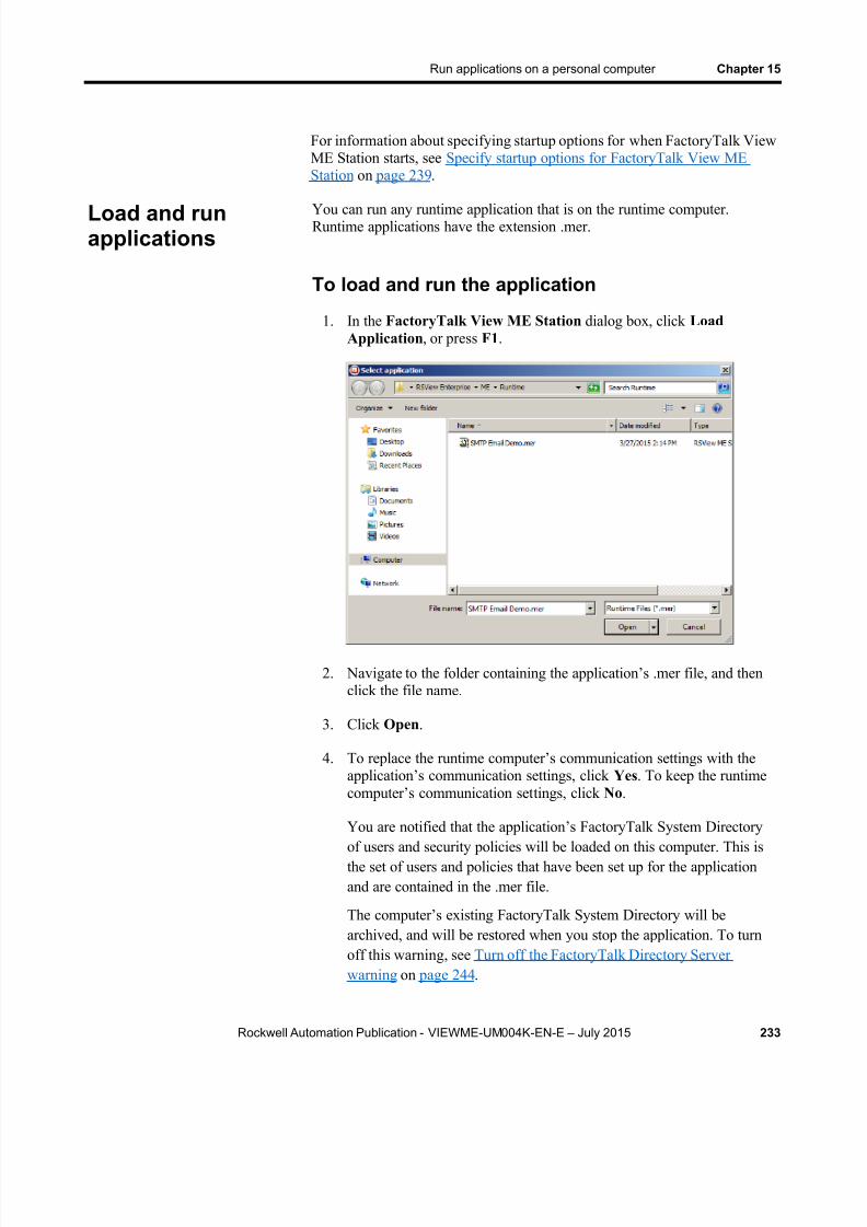
8/15/2019 Factory Talk View ME
http://slidepdf.com/reader/full/factory-talk-view-me 233/635
Run applications on a personal computer Chapter 15
Rockwell Automation Publication - VIEWME-UM004K-EN-E – July 2015 233
For information about specifying startup options for when FactoryTalk ViewME Station starts, see Specify startup options for FactoryTalk View MEStation on page 239 .
You can run any runtime application that is on the runtime computer.Runtime applications have the extension .mer.
To load and run the application
1. In the FactoryTalk View ME Station dialog box, click LoadApplication , or press F1 .
2. Navigate to the folder containing the application’s .mer file, and thenclick the file name.
3. Click Open .
4. To replace the runtime computer’s communication settings with theapplication’s communication settings, click Yes . To keep the runtimecomputer’s communication set tings, click No .
You are notified that the application’s FactoryTalk System Directoryof users and security policies will be loaded on this computer. This isthe set of users and policies that have been set up for the applicationand are contained in the .mer file.
The computer’s existing FactoryTalk System Directory will bearchived, and will be restored when you stop the application. To turnoff this warning, see Turn off the FactoryTalk Directory Serverwarning on page 244 .
Load and runapplications

8/15/2019 Factory Talk View ME
http://slidepdf.com/reader/full/factory-talk-view-me 234/635
Chapter 15 Run applications on a personal computer
234 Rockwell Automation Publication - VIEWME-UM004K-EN-E – July 2015
5. To continue, click Yes . To stop loading the application, click No .
If you continue, the application name is shown in the Currentapplication box in the FactoryTalk View ME Station dialog box.
6. To run the application, click Run Application .
The DEFAULT user is logged in. If a macro is assigned to theDEFAULT user, the macro runs.
To shut down an application, use one of thesemethods
Press a shutdown button in a graphic display.
If the application is set up to use a title bar with a Control box, clickthe Close button at the right end of the title bar.
If the application is set up to use a title bar with a Control box, on theControl menu at the left end of the title bar, click Close .
For information about using a title bar in graphic displays, see Title bar on page 75 .
For information about preventing unauthorized users from shutting downapplications, see Application examples on page 187 .
What happens when the application shuts down
When the application shuts down:
If you assigned a shutdown macro (in the Startup editor), the macroruns, assigning values to tags, and then the application stops.For information about the Startup editor, see Create runtimeapplications on page 221 .
FactoryTalk View ME Station closes.
The computer’s FactoryTalk System Directory is restored.
Shut downapplications

8/15/2019 Factory Talk View ME
http://slidepdf.com/reader/full/factory-talk-view-me 235/635
Run applications on a personal computer Chapter 15
Rockwell Automation Publication - VIEWME-UM004K-EN-E – July 2015 235
Edit device shortcuts
You can use FactoryTalk View ME Station to edit device shortcuts that have been set up in the application.
Before editing device shortcuts, load the application containing the deviceshortcut, as described on Load and run applications on page 233 .
To edi t device shor tcuts
1. In the FactoryTalk View ME Station dialog box, click ApplicationSettings .
2. Double-click Device Shortcuts .
3. Double-click the name of the shortcut to edit.
4. In the Edit ShortCuts dialog box, click the device you want theshortcut to point to, and then click OK .
Change applicationsettings

8/15/2019 Factory Talk View ME
http://slidepdf.com/reader/full/factory-talk-view-me 236/635
Chapter 15 Run applications on a personal computer
236 Rockwell Automation Publication - VIEWME-UM004K-EN-E – July 2015
To look up technical support contact information
1. In FactoryTalk View ME Station, click Terminal Settings .
2. Double-click About FactoryTalk View ME Station .
3. Click Technical Support .
The telephone number and URL for technical support are shown.
You can set up FactoryTalk Diagnostics on the runtime computer using theFactoryTalk View ME Station dialog box.
To set up FactoryTalk Diagnostics on the runtimecomputer
1. In FactoryTalk View ME Station, click Terminal Settings .
2. Double-click Diagnostics Setup .
The FactoryTalk Diagnostics Setup dialog box opens.
3. Set up FactoryTalk Diagnostics, as described in Use the DiagnosticsSetup tool on page 166 .
Look up contactinformation fortechnical support
Set up FactoryTalkDiagnostics on theruntime computer

8/15/2019 Factory Talk View ME
http://slidepdf.com/reader/full/factory-talk-view-me 237/635
Run applications on a personal computer Chapter 15
Rockwell Automation Publication - VIEWME-UM004K-EN-E – July 2015 237
If you plan to use KEPServer Enterprise and serial communications, youmust specify which COM port to use.
For information about setting up communications in KEPServer Enterprise,
see KEPServer Enterprise Help.
To specify the COM port to use for serialcommunications
1. In the FactoryTalk View ME Station dialog box, click TerminalSettings .
2. Double-click Networks and Communications .
3. Double-click KEPServer Serial Port ID’s .
4. In the KEPWare Serial Port ID’s dialog box, select the serial port IDyou specified when you set up the KEPServer Enterprise channel.
5. Click Edit Port.
6. In the Communication Ports dialog box, select the COM port to usefor KEPServer Enterprise communications.
Use RSLinx Enterprise to set up communication drivers for your runtimeapplication. You can set up the drivers directly in RSLinx Enterprise, oropen RSLinx Enterprise by using the FactoryTalk View ME Station dialog
box.
Set up serial portsfor use withKEPServerEnterprise
Set up RSLinxEnterprisecommunicationdrivers
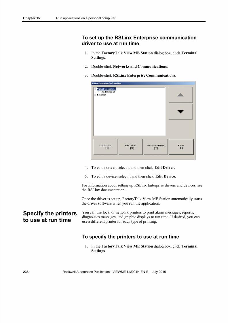
8/15/2019 Factory Talk View ME
http://slidepdf.com/reader/full/factory-talk-view-me 238/635
Chapter 15 Run applications on a personal computer
238 Rockwell Automation Publication - VIEWME-UM004K-EN-E – July 2015
To set up the RSLinx Enterprise communicationdriver to use at run time
1. In the FactoryTalk View ME Station dialog box, click TerminalSettings .
2. Double-click Networks and Communications .
3. Double-click RSLinx Enterprise Communications .
4. To edit a driver, select it and then click Edit Driver .
5. To edit a device, select it and then click Edit Device .
For information about setting up RSLinx Enterprise drivers and devices, seethe RSLinx documentation.
Once the driver is set up, FactoryTalk View ME Station automatically startsthe driver software when you run the application.
You can use local or network printers to print alarm messages, reports,diagnostics messages, and graphic displays at run time. If desired, you canuse a different printer for each type of printing.
To specify the printers to use at run time
1. In the FactoryTalk View ME Station dialog box, click TerminalSettings .
Specify the printers
to use at run time

8/15/2019 Factory Talk View ME
http://slidepdf.com/reader/full/factory-talk-view-me 239/635
Run applications on a personal computer Chapter 15
Rockwell Automation Publication - VIEWME-UM004K-EN-E – July 2015 239
2. Double-click Print Setup .
3. Double-click the type of printing to set up.
4. Modify the print options as required.
For detailed information about printer options, refer to your Windowsdocumentation.
This section describes how to start FactoryTalk View ME Station
automatically when Windows starts, and describes startup options forFactoryTalk View ME Station.
When you start FactoryTalk View ME Station, you can:
Run an application
Load an application
Automatically delete an application’s log files before running theapplication
Specify startupoptions forFactoryTalk ViewME Station

8/15/2019 Factory Talk View ME
http://slidepdf.com/reader/full/factory-talk-view-me 240/635
Chapter 15 Run applications on a personal computer
240 Rockwell Automation Publication - VIEWME-UM004K-EN-E – July 2015
Replace RSLinx Enterprise communications on the runtime computerwith the application’s settings
By default, the option to start FactoryTalk View ME Station when Windows
starts is turned off. The settings in this section apply only if you wantFactoryTalk View ME Station to start automatically when Windows starts.
To start FactoryTalk View ME Station and run anapplication when Windows starts
1. In the FactoryTalk View ME Station dialog box, load the applicationthat you want to run.
For details, see Load and run applications on page 233 .
2. Click Terminal Settings.
3. Double-click FactoryTalk View ME Station Startup.
4. Click Run Current Application.
This option is not available if you have not loaded an application yet.

8/15/2019 Factory Talk View ME
http://slidepdf.com/reader/full/factory-talk-view-me 241/635
Run applications on a personal computer Chapter 15
Rockwell Automation Publication - VIEWME-UM004K-EN-E – July 2015 241
5. Click Run Options.
6. Specify whether to replace the RSLinx Enterprise communicationsettings on the runtime computer with the application’s settings whenthe application starts.
7. Specify whether to delete the application’s log files on startup.
To start FactoryTalk View ME Station withoutrunning an application when Windows starts
1. In the FactoryTalk View ME Station dialog box, click TerminalSettings .

8/15/2019 Factory Talk View ME
http://slidepdf.com/reader/full/factory-talk-view-me 242/635
Chapter 15 Run applications on a personal computer
242 Rockwell Automation Publication - VIEWME-UM004K-EN-E – July 2015
2. Double-click FactoryTalk View ME Station Startup.
3. Click Go to Configuration Mode.
4. Click Configuration Mode Options.
5. Specify whether to load the current application when FactoryTalkView ME Station starts.
This option is not available if you have not loaded an application.
6. Specify whether to replace the RSLinx Enterprise communicationsettings on the runtime computer with the application’s settings whenthe application starts.

8/15/2019 Factory Talk View ME
http://slidepdf.com/reader/full/factory-talk-view-me 243/635
Run applications on a personal computer Chapter 15
Rockwell Automation Publication - VIEWME-UM004K-EN-E – July 2015 243
This option is not available if you have not loaded an application.
Use Windows Server 2012, Windows 8.1, Windows8, Windows 7, and Windows Server 2008 with MEStation
In order to deploy a HMI system on Windows Server 2012, Windows 8.1,Windows 8, Windows 7, and Windows Server 2008, one of the followingoptions needs to be selected:
The operator will need to log into Windows as a member of theAdministrators group. The operator can then use ME Station forWindows.
An administrator can disable the UAC. This allows a Windows userthat is a member of the Users group to use ME Station for Windows.
An operator that is a member of the Users group who knows anAdministrators password, and can provide authentication when UAC
prompts, can use ME Station.
This allows the operator to load and run an MER as well as configure MEStation for Windows using the Graphical User Interface.
When you run your application, FactoryTalk View ME Station stores logfiles for alarms and data logging (if you use these features). When you startFactoryTalk View ME Station, you can delete the alarm and data log files for
the loaded application, or for all the applications on the runtime computer.
Run a newer version of the application
If you run a newer version of an application, the alarm log file for the olderversion is deleted automatically. The data log file for the older version isretained, to allow the display of historical data in trends.
For more information about the alarm log file, see The alarm log file on page129 .
For more information about data log files, see Change the data log modelused at run time on page 522 .
Delete log files onthe runtimecomputer
8/15/2019 Factory Talk View ME
http://slidepdf.com/reader/full/factory-talk-view-me 244/635
Chapter 15 Run applications on a personal computer
244 Rockwell Automation Publication - VIEWME-UM004K-EN-E – July 2015
Delete log files manually
To dele te log f i les for the loaded app l ica t ion
In the FactoryTalk View ME Station dialog box, click Yes beside theDelete Log Files Before Running button.
All alarm and data log files for the loaded application are deleted.
To dele te log f i les for a l l appl ica t ions on the runt imecompute r
1. In the FactoryTalk View ME Station dialog box, click TerminalSettings.
2. Double-click Delete Log Files. 3. Click Yes .
Log files for data log models that use the default path are deleted. All alarmlog files are deleted.
When you load an application, you are notified that the application’sFactoryTalk System Directory of users and security policies will be loadedon the computer. The computer’s existing FactoryTalk System Directory isarchived while you run the application. It is restored when you stop theapplication. You can turn off this notification warning.
To turn off the overwrite warning
1. In the FactoryTalk View ME Station dialog box, click TerminalSettings.
2. Double-click System Directory Overwrite Warning.
3. Click No .
Time, date, and number formats are used by these graphic objects:
Numeric display
Gauge
Time and date display
Trend
Alarm banner
Alarm list
Turn off theFactoryTalkDirectory Serverwarning
Specify time, date,and number formats

8/15/2019 Factory Talk View ME
http://slidepdf.com/reader/full/factory-talk-view-me 245/635
Run applications on a personal computer Chapter 15
Rockwell Automation Publication - VIEWME-UM004K-EN-E – July 2015 245
The time and date formats are also used when printing the alarm historyreport (using the Print Alarm History button). The numeric and time and dateembedded variables also use number, time, and date formats.
All objects use the time, date, and number formats of the current applicationlanguage. For example, if the application language uses a comma for thedecimal symbol, numeric variables use a comma for the decimal symbol.
For information about using multiple languages, see Set up languageswitching on page 197 .
Use the DeskLock tool to prevent users from switching to another softwareapplication or having access to the desktop at run time.
This tool can have far-reaching effects on your operating system. TheDeskLock tool can replace the standard Windows Server 2012, Windows 8.1,
Windows 8, Windows 7, and Windows Server 2008 non-configured desktopwith a customized desktop. The customized desktop is intended to preventoperators from having access to other applications and operating systemfunctions such as restarting Windows or shutting down tasks. You can alsouse the tool to set up an automatic Windows logon and to specify optionssuch as which software applications are allowed or not allowed to run on thecomputer.
Before using the tool, read the DeskLock Help completely.
To open the DeskLock tool
From the Windows Start menu, select Programs > RockwellSoftware > FactoryTalk View > Tools , and then click DeskLock.
For details about using the tool, see the tool’s Help.
Use the DeskLocktool

8/15/2019 Factory Talk View ME
http://slidepdf.com/reader/full/factory-talk-view-me 246/635
Chapter 15 Run applications on a personal computer
246 Rockwell Automation Publication - VIEWME-UM004K-EN-E – July 2015
8/15/2019 Factory Talk View ME
http://slidepdf.com/reader/full/factory-talk-view-me 247/635
Rockwell Automation Publication - VIEWME-UM004K-EN-E – July 2015 247
Chapter 16
Transfer applications to aPanelView Plus terminal
This chapter describes:
Start FactoryTalk View ME Station
Set up communication drivers to transfer applications to a PanelViewPlus 7, PanelView Plus 6, PanelView Plus, PanelView Plus Compact,
or PanelView Plus CE terminal Transfer applications and TrueType fonts to a PanelView Plus 7,
PanelView Plus 6, PanelView Plus, PanelView Plus Compact, orPanelView Plus CE terminal
Upload applications from a terminal to the development computer
Compare applications on the development computer with applicationson the terminal
For information about using your application at run time, see Use yourapplication on page 257
For information about using FactoryTalk View ME Station on the terminal,including setting up communications, printers, and input devices, see the
PanelView Plus Terminals User Manual .
Follow these steps to:
Install hardware and software on a PanelView Plus 7, PanelView Plus6, PanelView Plus, PanelView Plus Compact, or PanelView Plus CEterminal.
Transfer your application to the PanelView Plus 7, PanelView Plus 6,PanelView Plus, PanelView Plus Compact, or PanelView Plus CE
terminal.
For information about installing FactoryTalk View ME Station, see the FactoryTalk View Machine Edition Installation Guide .
Steps fortransferringapplications to aPanelView Plusterminal
8/15/2019 Factory Talk View ME
http://slidepdf.com/reader/full/factory-talk-view-me 248/635
Chapter 16 Transfer applications to a PanelView Plus terminal
248 Rockwell Automation Publication - VIEWME-UM004K-EN-E – July 2015
Install hardware and software on a PanelView Plusterminal
1. If you will be printing displays, alarms, reports, or diagnosticsmessages, connect a printer to the USB or Network port.
PanelView Plus 7 and PanelView Plus 6 terminals support a widerange of printers. For a list of supported printers, see Answer ID111636 in Rockwell Automation Knowledgebase.
PanelView Plus terminals support printing using the MicrosoftWindows CE PCL3 printer driver, which is already installed on theterminal. Printing is supported for most laser and ink-jet printers. Ifyou have problems printing, check that your printer is compatible withthe PCL3 printer driver.
2. If you are using KEPServer Enterprise, enable the driver you need onthe terminal. For more information, see KEPServer Enterprisedocumentation .
For information about OPC data servers, see Set up communications on page 79 .
3. If your application uses third-party ActiveX objects, install and registerthe Windows CE version of the objects on the terminal.
For information about ActiveX objects, see Use ActiveX objects on page 353 .
Install printers on a PanelView Plus terminal
If you will be printing displays, alarms, reports, or diagnostics messages,connect a printer to the USB or Network port.
PanelView Plus terminals support printing using the Microsoft Windows CEPCL3 printer driver, which is already installed on the terminal. Printing issupported for most laser and ink-jet printers. If you have problems printing,
check that your printer is compatible with the PCL3 printer driver.The PanelView Plus terminal is a closed box , which means you must orderany software your application will need when you order the system. Allsoftware comes pre-installed.

8/15/2019 Factory Talk View ME
http://slidepdf.com/reader/full/factory-talk-view-me 249/635
Transfer applications to a PanelView Plus terminal Chapter 16
Rockwell Automation Publication - VIEWME-UM004K-EN-E – July 2015 249
Install hardware and software on a PanelView Plus7 or PanelView Plus 6 terminal
1. If you will be printing displays, alarms, reports, or diagnosticsmessages, connect a printer to the USB or Network port.
PanelView Plus 7 and PanelView Plus 6 terminals incorporate theJETCET PRINT solution for Microsoft Windows CE devices,supporting select Canon, Epson, Hewlett-Packard, and Brother
printers. Plug-and-play installation is supported for these printers aswell as manual installation if a suitable JETCET print driver isavailable.
2. If you are using KEPServer Enterprise, enable the driver you need onthe terminal. For more information, see KEPServer Enterprisedocumentation.
For information about OPC data servers, see Set up communications on page 79 .
3. If your application uses third-party ActiveX objects, install and registerthe Windows CE version of the objects on the terminal.
For information about ActiveX objects, see Use ActiveX objects on page 353 .
Install printers on a PanelView Plus 7 or PanelViewPlus 6 terminal
If you will be printing displays, alarms, reports, or diagnostics messages,connect a printer to the USB or Network port.
PanelView Plus 7 and PanelView Plus 6 terminals incorporates the JETCETPRINT solution for Microsoft Windows CE devices, supporting selectCanon, Epson, Hewlett-Packard, and Brother printers. Plug-and-playinstallation is supported for these printers as well as manual installation if asuitable JETCET print driver is available.
Print support is centrally managed and independent of the application. Youcan add and configure a new printer from the desktop control panel. Printerconfigurations include the printer name, printer driver, port, and port-specific
parameters. New configurations are retained through a power cycle.
8/15/2019 Factory Talk View ME
http://slidepdf.com/reader/full/factory-talk-view-me 250/635
Chapter 16 Transfer applications to a PanelView Plus terminal
250 Rockwell Automation Publication - VIEWME-UM004K-EN-E – July 2015
Transfer applications
1. On the PanelView Plus 7, PanelView Plus 6, PanelView Plus,PanelView Plus Compact, or PanelView Plus CE terminal, startFactoryTalk View ME Station.
For more information, see Start FactoryTalk View ME Station on page250 .
2. In FactoryTalk View ME Station, if you’re transferring via a serialconnection, specify and set up the serial driver. If you are usingEthernet for the transfer, you can skip this step.
For more information, see Specify the driver to use for the transfer on page 251 .
3. On the development computer, set up the RSLinx Enterprise driver touse for the transfer.
For more information, see Set up a driver for the transfer on thedevelopment computer on page 252 .
4. Move the application to the PanelView Plus 7, PanelView Plus 6,PanelView Plus, PanelView Plus Compact, or PanelView Plus CEterminal using the Transfer Utility tool.
For more information, see Download applications and Windows
TrueType fonts on page 253 .
You can also transfer applications to the terminal using a Flash Card. Forinformation about this method, see the PanelView Plus Terminals User
Manual .
To start FactoryTalk View ME Station on aPanelView Plus 7 or PanelView Plus 6 terminal
From the Windows Start menu, select Programs > RockwellSoftware , and then click FactoryTalk View ME Station .
Start FactoryTalkView ME Station
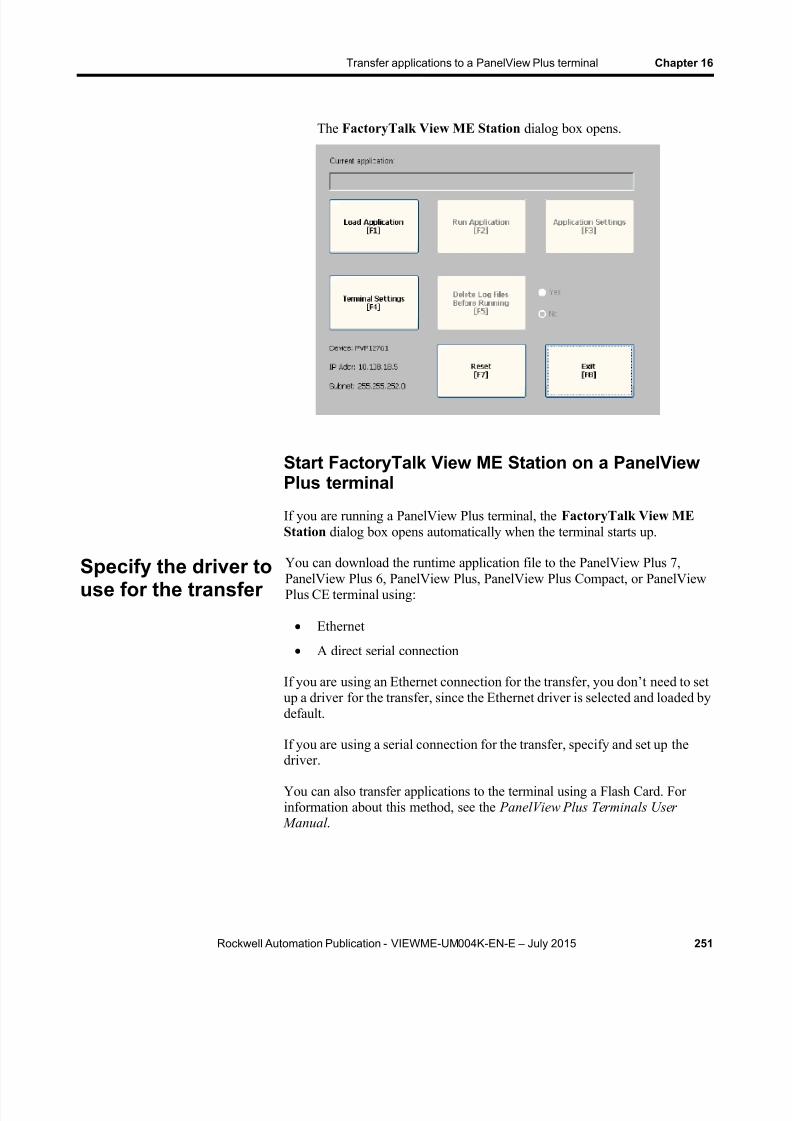
8/15/2019 Factory Talk View ME
http://slidepdf.com/reader/full/factory-talk-view-me 251/635
Transfer applications to a PanelView Plus terminal Chapter 16
Rockwell Automation Publication - VIEWME-UM004K-EN-E – July 2015 251
The FactoryTalk View ME Station dialog box opens.
Start FactoryTalk View ME Station on a PanelViewPlus terminal
If you are running a PanelView Plus terminal, the FactoryTalk View MEStation dialog box opens automatically when the terminal starts up.
You can download the runtime application file to the PanelView Plus 7,PanelView Plus 6, PanelView Plus, PanelView Plus Compact, or PanelViewPlus CE terminal using:
Ethernet
A direct serial connection
If you are using an Ethernet connection for the transfer, you don’t need to setup a driver for the transfer, since the Ethernet driver is selected and loaded bydefault.
If you are using a serial connection for the transfer, specify and set up the
driver.You can also transfer applications to the terminal using a Flash Card. Forinformation about this method, see the PanelView Plus Terminals User
Manual .
Specify the driver touse for the transfer

8/15/2019 Factory Talk View ME
http://slidepdf.com/reader/full/factory-talk-view-me 252/635
Chapter 16 Transfer applications to a PanelView Plus terminal
252 Rockwell Automation Publication - VIEWME-UM004K-EN-E – July 2015
To specify and set up a serial driver for the transfer
1. In the FactoryTalk View ME Station dialog box, click TerminalSettings .
2. Double-click Networks and Communications .
3. In the Networks and Communications dialog box, double-clickRSLinx Enterprise Communications .
4. Click the Serial-DF1 driver, and then click Edit Driver .
5. Select Use Auto-Configuration , and then click Edit .
6. In the dialog box that opens, select Yes , and then click OK .
Auto configuration works with most devices, including Logix5000 andPLC-5. If auto configuration is not successful for your device, return tothese steps, select No, and continue to step 7.
7. Set up the driver, and then click OK . If you are using auto
configuration, skip this step.
On the development computer, set up the RSLinx Enterprise driver that youwill use to download your application to the PanelView Plus 7, PanelViewPlus 6, PanelView Plus, PanelView Plus Compact, or PanelView Plus CEterminal.
Use one of these drivers for the transfer:
Serial-DF1 — Use for a serial transfer.
Set up a driver forthe transfer on thedevelopmentcomputer
8/15/2019 Factory Talk View ME
http://slidepdf.com/reader/full/factory-talk-view-me 253/635
Transfer applications to a PanelView Plus terminal Chapter 16
Rockwell Automation Publication - VIEWME-UM004K-EN-E – July 2015 253
Ethernet — Use with an Ethernet connection.
For information about setting up drivers in RSLinx Enterprise, see RSLinxHelp.
Use the Transfer Utility to download your runtime application and WindowsTrueType font files from the development computer to the PanelView Plus7, PanelView Plus 6, PanelView Plus, PanelView Plus Compact, orPanelView Plus CE terminal.
Runtime applications have the extension .mer. Windows TrueType font fileshave the extension .ttf or .ttc.
For information about creating the runtime application file, see Createruntime applications on page 221 .
About the download
You can use a serial or Ethernet connection between the developmentcomputer and the PanelView Plus or PanelView Plus CE terminaldestination. You must use one of the drivers listed in the previous section forthe download.
You can download while an application is running on the runtime computer.
You can download:
Multiple applications (one at a time) to the same runtime computer. A new copy of the application currently running on the runtime
computer, for use the next time the application is started.
If the download process fails or is canceled, the application file will bedeleted from the destination directories. Make a copy of the application file
before you begin and make sure there is enough storage space on thedestination computer.
Serial downloads
To perform a serial download, make sure the terminal is connected to thedevelopment computer using the correct cable. Connect a PanelView Plus 7,PanelView Plus 6, PanelView Plus, PanelView Plus Compact, or PanelViewPlus CE terminal to the PC using the Allen-Bradley serial cable 2711-NC13.
To start the Transf er Uti l i ty too l
On the development computer, do one of the following:
Downloadapplications andWindows TrueTypefonts

8/15/2019 Factory Talk View ME
http://slidepdf.com/reader/full/factory-talk-view-me 254/635
Chapter 16 Transfer applications to a PanelView Plus terminal
254 Rockwell Automation Publication - VIEWME-UM004K-EN-E – July 2015
In FactoryTalk View Studio, from the Tools menu, select TransferUtility .
From the Windows Start menu, select Programs > Rockwell
Software > FactoryTalk View > Tools , and then click ME TransferUtility .
For details about using the utility, see the utility’s Help.
Use the Transfer Utility to upload your runtime application from thePanelView Plus 7, PanelView Plus 6, PanelView Plus, PanelView PlusCompact, or PanelView Plus CE terminal to the development computer.Runtime applications have the extension .mer.
Any password changes that were made while the application was running aresaved in the .mer file and will be uploaded.
If the upload process fails or is canceled, the application file will be deletedfrom the destination directory. Make sure there is enough storage space onthe destination computer.
About the upload
You can upload while an application is running on the runtime computer.You can upload an existing copy of the application currently running on theruntime computer.
Upload applicationsfrom the PanelView
Plus 7, PanelViewPlus 6, PanelViewPlus, or PanelViewPlus CE terminal

8/15/2019 Factory Talk View ME
http://slidepdf.com/reader/full/factory-talk-view-me 255/635
Transfer applications to a PanelView Plus terminal Chapter 16
Rockwell Automation Publication - VIEWME-UM004K-EN-E – July 2015 255
Note: PanelView Plus 7 or PanelView Plus 6 terminals cannotprocess a Gradient Fill that uses a Diagonal Up or DiagonalDown direction, nor can the PanelView Plus 7 or PanelViewPlus 6 terminal apply a Gradient Fill to a rotated object. Whilerunning an MER on a PanelView Plus 7 or PanelView Plus 6terminal, the gradient attributes will be animated using thegradient fill starting color as the object’s solid colorbackground.When running the MER on a computer, the system canprocess all gradient fills and this warning does not apply.
Serial uploads
To perform a serial upload, make sure the terminal is connected to thedevelopment computer using the correct cable. Connect a PanelView Plus 7,
PanelView Plus 6, PanelView Plus, PanelView Plus Compact, or PanelViewPlus CE terminal to the PC using the Allen-Bradley serial cable 2711-NC13.
For details about performing the upload, see Help for the Transfer Utility.
You can also use the Transfer Utility tool to compare an application on thedevelopment computer with an application on the terminal. The comparisontool can tell you whether the files are identical or different. The comparisontool detects differences using a binary checksum. It is not possible to listindividual differences between the files.
Compareapplications

8/15/2019 Factory Talk View ME
http://slidepdf.com/reader/full/factory-talk-view-me 256/635
Chapter 16 Transfer applications to a PanelView Plus terminal
256 Rockwell Automation Publication - VIEWME-UM004K-EN-E – July 2015
8/15/2019 Factory Talk View ME
http://slidepdf.com/reader/full/factory-talk-view-me 257/635
Rockwell Automation Publication - VIEWME-UM004K-EN-E – July 2015 257
Chapter 17
Use your application
This chapter describes:
Log in and log out
Change passwords
Add a user or group and delete a user or group
Modify group membership
Unlock users
Enable and disable users
Change user properties
Enter numeric and string values
Change tag values
View tag data
View alarms and messages
View information about runtime communication errors
Change languages
For information about navigating between displays, see Set up displaynavigation on page 213 .
For information about navigating between and using the graphic objects in adisplay, see Set up how objects are used at run time on page 392 .
An application’s security configuration may contain native FactoryTalkSecurity users or Windows-linked users. Windows- linked user’s credentialsare contained on either the local PC or in a domain. To support userauthentication in a Windows domain, additional PanelView Plus terminalconfiguration is required.
FactoryTalk View ME 8.0 and later supports PanelView Plus 7, andPanelView Plus 6 domain authentication against Windows Server 2012,Windows Server 2008, and Windows Server 2003 domains in the followingmechanism:
LDAP (Lightweight Directory Access Protocol)
LDAP over SSL (Secure Sockets Layer)
Log in to theapplication
Domainauthentication

8/15/2019 Factory Talk View ME
http://slidepdf.com/reader/full/factory-talk-view-me 258/635
Chapter 17 Use your application
258 Rockwell Automation Publication - VIEWME-UM004K-EN-E – July 2015
For details, see Configure FactoryTalk View ME 8.0 and later terminals forDomain authentication on page 258 .
FactoryTalk View ME releases prior to 8.0 support domain authentication
against Windows Server 2000, and Windows Server 2003 domains. Fordetails, see Configure FactoryTalk View ME prior to 8.0 terminals forDomain authentication on page 262 .
Configure FactoryTalk View ME 8.0 and laterterminals for Domain authentication
To con f igure LDAP se t t ings on a FactoryTalk View ME 8.0or later terminal
1. In the FactoryTalk View ME Station dialog box, click TerminalSettings.
2. Double-click Networks and Communications .
3. Double-click LDAP Configuration.
4. On FactoryTalk View ME 8.1 or later terminals, select one of thefollowing Authentication Mode options:
Use Windows and LDAP only authentication to use Windowsauthentication mode to log in first. If Windows authentication fails,
LDAP without SSL authentication mode will be used to log in. Use LDAP only authentication to use LDAP without SSL
authentication mode.
Use LDAP over SSL authentication to use LDAP over SSLauthentication mode.
5. On FactoryTalk View ME 8.0 terminals, select one of the followingUse SSL options:
Yes to use LDAP over SSL authentication mode.
No use LDAP without SSL authentication mode.
6. Do one of the following:

8/15/2019 Factory Talk View ME
http://slidepdf.com/reader/full/factory-talk-view-me 259/635
Use your application Chapter 17
Rockwell Automation Publication - VIEWME-UM004K-EN-E – July 2015 259
In the Server FQDN box, enter FQDN (fully qualified domainname), for example, FTV1TT45.domain08r2.domain03.com.
Note: FQDN is a DNS name that uniquely identifies the computer onthe network. By default, it is a concatenation of the host name,the primary DNS suffix, and a period.You can find the FQDN from the Network Identification tab ofthe the properties page for My Computer on the Domainserver.If SSL is enabled, you need to have the root certificate on yourlocal terminal. For more information about obtaining rootcertificate, see To obtain a root certificate on page 260 .
In the DNS-Style Domain Name box, enter the domain name, forexample, domain08r2.domain03.com .
The Port field is automatically filled.
7. On FactoryTalk View ME 8.1 or later terminals, select one of thefollowing Group Membership options:
Use user attribute (faster) - Security subsystem will only evaluatedomain group membership against the domain group(s) to whichthe user explicitly belongs. Nested domain group membership willnot be evaluated. This provides much faster domain authenticationthan the Use nested groups option. When using this option, it iscritical that the domain group(s) to which the target usercommunity belongs is(are) added to FactoryTalk Securityexplicitly, or added to a native FactoryTalk group.
Use nested groups (slower) - Security subsystem will evaluatedomain group membership by querying the domain. The domainquery returns a list of all the groups to which the user belongs.User memberof attribute will not be evaluated. This providesslower but more complete evaluation of a user’s domain groupmembership. When using this option, it is recommended that thedomain group(s) to which the target user community belongsis(are) added to FactoryTalk Security explicitly, or added to anative FactoryTalk group.
For example, User A is a member of domain group Line1, andUser A memberof attribute explicitly lists Line1. User B is amember of domain group Shift3, and User B memberof attributeexplicitly lists Shift3. Shift3 is a subgroup of Line1. The HMIdesigner adds the domain group Line1 to FactoryTalk Security,and adds and configures the group in ME Runtime Security (Athrough P codes). On the PanelView Plus 7, or PanelView Plus 6terminal:
When the HMI designer selects Use user attribute (faster) , atruntime, User A can successfully authenticate; but User Bcannot authenticate because domain group Shift3 is subgroup
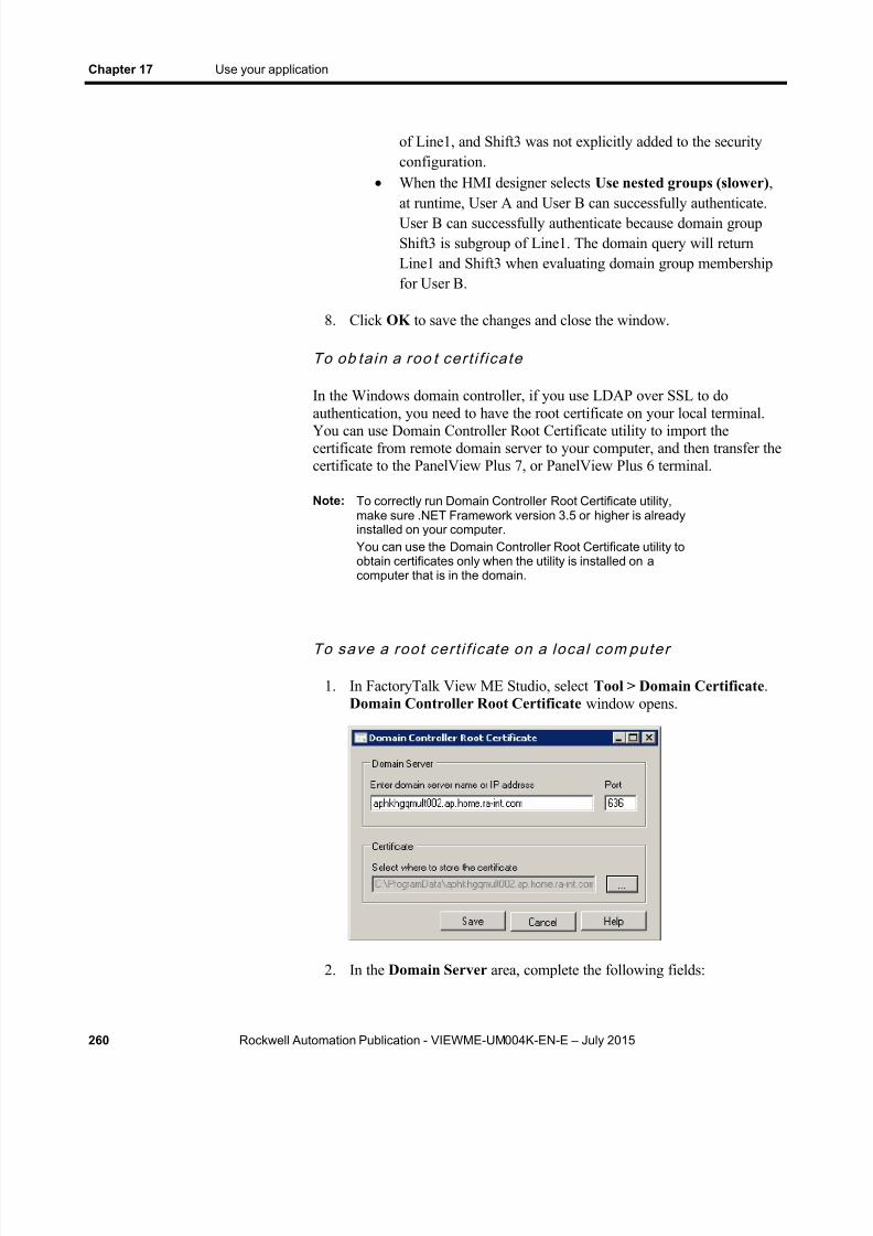
8/15/2019 Factory Talk View ME
http://slidepdf.com/reader/full/factory-talk-view-me 260/635

8/15/2019 Factory Talk View ME
http://slidepdf.com/reader/full/factory-talk-view-me 261/635
Use your application Chapter 17
Rockwell Automation Publication - VIEWME-UM004K-EN-E – July 2015 261
In the Enter domain server name or IP address field, enter theserver name or IP address of the domain server. If the computer isalready in a domain, the utility automatically detects and shows thedomain server address in this field.
In the Port field, enter the port of the domain server for LDAPover SSL. The default value is 636.
3. In the Certificate area, click the Browse (...) button to specify wherethe certificate file will be stored. The default location is:
(Windows XP) C:\Documents and Settings\AllUsers\Application Data
(Windows Server 2012, Windows 8.1, Windows 8, Windows 7,and Windows Server 2008) C:\ProgramData
The default file name is domainserver.cer , where domainserver is thedomain server name or IP address.
4. Click Save to complete and close the window.
To imp ort a roo t cert if icate on a FactoryTalk View ME 8.0 orlater terminal
1. Copy the certificate file to a removable device.
2. Plug the removable device, containing the certificate file, into theterminal.
3. On the terminal, select Start > Settings > Control Panel >Certificates .
4. In the Certificates dialog box, click Import .
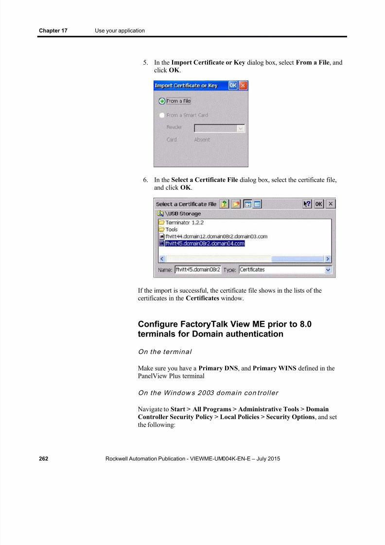
8/15/2019 Factory Talk View ME
http://slidepdf.com/reader/full/factory-talk-view-me 262/635
Chapter 17 Use your application
262 Rockwell Automation Publication - VIEWME-UM004K-EN-E – July 2015
5. In the Import Certificate or Key dialog box, select From a File , andclick OK .
6. In the Select a Certificate File dialog box, select the certificate file,and click OK .
If the import is successful, the certificate file shows in the lists of thecertificates in the Certificates window.
Configure FactoryTalk View ME prior to 8.0terminals for Domain authentication
On the te rminal
Make sure you have a Primary DNS , and Primary WINS defined in thePanelView Plus terminal
On the Window s 2003 domain con t ro l ler
Navigate to Start > All Programs > Administrative Tools > DomainController Security Policy > Local Policies > Security Options , and setthe following:
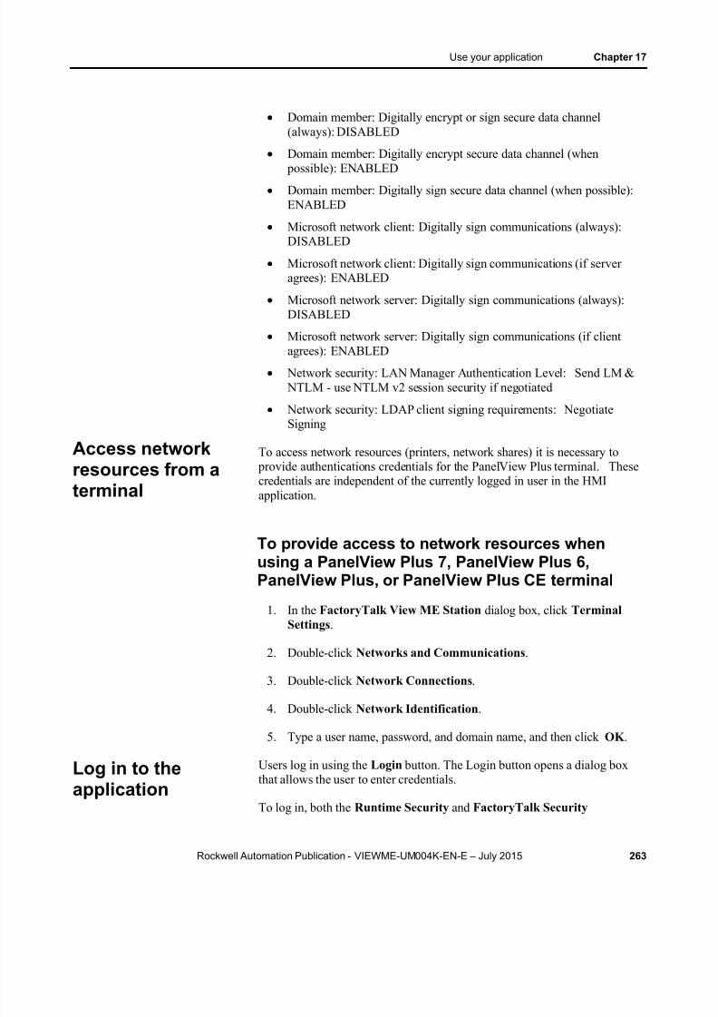
8/15/2019 Factory Talk View ME
http://slidepdf.com/reader/full/factory-talk-view-me 263/635
Use your application Chapter 17
Rockwell Automation Publication - VIEWME-UM004K-EN-E – July 2015 263
Domain member: Digitally encrypt or sign secure data channel(always): DISABLED
Domain member: Digitally encrypt secure data channel (when
possible): ENABLED Domain member: Digitally sign secure data channel (when possible):
ENABLED
Microsoft network client: Digitally sign communications (always):DISABLED
Microsoft network client: Digitally sign communications (if serveragrees): ENABLED
Microsoft network server: Digitally sign communications (always):DISABLED
Microsoft network server: Digitally sign communications (if clientagrees): ENABLED
Network security: LAN Manager Authentication Level: Send LM & NTLM - use NTLM v2 session security if negotiated
Network security: LDAP client signing requirements: NegotiateSigning
To access network resources (printers, network shares) it is necessary to provide authentications credentials for the PanelView Plus terminal. Thesecredentials are independent of the currently logged in user in the HMIapplication.
To provide access to network resources whenusing a PanelView Plus 7, PanelView Plus 6,PanelView Plus, or PanelView Plus CE terminal
1. In the FactoryTalk View ME Station dialog box, click TerminalSettings .
2. Double-click Networks and Communications .
3. Double-click Network Connections .
4. Double-click Network Identification .
5. Type a user name, password, and domain name, and then click OK .
Users log in using the Login button. The Login button opens a dialog boxthat allows the user to enter credentials.
To log in, both the Runtime Security and FactoryTalk Security
Access networkresources from aterminal
Log in to theapplication

8/15/2019 Factory Talk View ME
http://slidepdf.com/reader/full/factory-talk-view-me 264/635
Chapter 17 Use your application
264 Rockwell Automation Publication - VIEWME-UM004K-EN-E – July 2015
configuration must contain the individual user account, or a group of whichthe user account is a member.
For information about setting up user accounts and passwords, see Set up
security on page 175 .
Note: When adding users and groups to FactoryTalk security, it isimportant to remember that a user cannot log in to the runningapplication unless the user or group is configured in RuntimeSecurity .
4.00 and later applications
To log in, the ME Runtime 4.00 and later tab in Runtime Security configuration must contain either the individual user account, or a group ofwhich the user is a member.
3.20 and earlier applications
To log in, the ME Runtime 3.20 and earlier tab in Runtime Security configuration must contain either the individual user account, or a group ofwhich the user is a member.
If a user account is disabled, or locked, the user cannot successfully log inuntil the user account is enabled or unlocked
To log in
1. Press the Login button. The Login window opens.

8/15/2019 Factory Talk View ME
http://slidepdf.com/reader/full/factory-talk-view-me 265/635
Use your application Chapter 17
Rockwell Automation Publication - VIEWME-UM004K-EN-E – July 2015 265
Note: At runtime: If the Visible check box is clear in the General tab of the
Login Button Properties window, the Domain box ishidden in the Login window.
If both the Visible check box and the Disable check box areselected in the General tab of the Login Button Properties window, the Domain box is read-only in the Login window.
If the Visible check box is selected, and the Disable checkbox is clear in the General tab of the Login ButtonProperties window, the Domain box can be edited in theLogin window.
If there are only FactoryTalk users in the application, theDomain box is usually hidden.
2. Press the Domain button, or press F1 on an external keyboard. Thestring pop-up keyboard opens. For details about using the keyboard,see Use the string pop-up keyboard on page 283 .
Type the domain name in the string pop-up keyboard, or on an externalkeyboard, and then press Enter .
3. Press the UserName button, or press F2 on an external keyboard.Typeyour user name in the string pop-up keyboard, or on an externalkeyboard, and then press Enter .
8/15/2019 Factory Talk View ME
http://slidepdf.com/reader/full/factory-talk-view-me 266/635
Chapter 17 Use your application
266 Rockwell Automation Publication - VIEWME-UM004K-EN-E – July 2015
If the Hide User Name Entry check box is selected in the General tabof the Login Button Properties window, the user name entered here ismasked by #
For 4.00 and later runtime applications, the name is not case sensitive.For RSView 3.20 and earlier applications, the name must use ALLCAPS.
4. To enter the password, press the Password button, or press F3 on anexternal keyboard. Type the password in the string pop-up keyboard, oron an external keyboard, and then press Enter . For 4.00 and laterruntime applications, the password is case sensitive. For RSView 3.20and earlier applications, the password is not case sensitive.
5. To close the Login window and complete the login, press Enter .
What happens when a user logs in
When a user logs in:
If the previous user did not log out, the previous user is logged outnow. If a logout macro is set up for the previous user, the logout macroruns, assigning values to tags. If the previous user belongs to a group,and a logout macro is set up for the group, the logout macro runs.
The new user is logged in.
If a login macro is set up for the new user, the macro runs, assigningvalues to tags. If the new user belongs to a group, and a login macro isset up for the group, the login macro runs.
Problems with logging in
Login is unsuccessful under these circumstances:
If the graphic display changes remotely before the user has finishedlogging in, the login is cancelled.
If the entered user name does not match a user account configured inRuntime Security
If the entered user name is not a member of a group configured inRuntime Security .
If the entered user password does not match the user account passwordconfigured in Runtime Security .
If the user account is disabled or locked
8/15/2019 Factory Talk View ME
http://slidepdf.com/reader/full/factory-talk-view-me 267/635
Use your application Chapter 17
Rockwell Automation Publication - VIEWME-UM004K-EN-E – July 2015 267
If a PanelView Plus 7, PanelView Plus 6, PanelView Plus, PanelViewPlus Compact, or PanelView Plus CE terminal's time is notsynchronized with the domain controller, domain users cannot log inon the terminal. To enable the users to log in, synchronize theterminal’s time with the domain controller.
You can use the Password button to change password at runtime. Any password changes made at run time are saved in the .mer file.
The Password button supports two modes of runtime operations:
Allows the user to modify their own password
Allows the user to modify any user password
Note: When designing the application in FactoryTalk View Studio,you must consider which users and groups can access this
button, and how to control that access.
The Password button operational mode is configured in FactoryTalk ViewStudio, and cannot be changed at runtime.
Note: For 5.00 and later applications, it is recommended that youcan convert the runtime application mer file to adevelopment application in order to preserve passwordchanges the next time the runtime application file is created.
For versions prior to 5.00, it is recommended that whenpasswords are changed at run time, the same passwordchanges are made on the development computer.Otherwise, the next time you create the .mer file, thepassword changes will be lost. For more information, seeConvert runtime application files to developmentapplications on page 226 .
For 3.20 and earlier applications, you cannot changepasswords in FactoryTalk View ME Station. To change apassword for a FactoryTalk View user, use the RuntimeSecurity editor in FactoryTalk View Studio, and thenrecreate the runtime application and download the .mer fileagain. To change a password for a Windows user, use theWindows Control Panel.
The passwords for Windows-linked users can only bechanged in Windows.
To change your current password
1. Press the Password button.
Change passwords

8/15/2019 Factory Talk View ME
http://slidepdf.com/reader/full/factory-talk-view-me 268/635
Chapter 17 Use your application
268 Rockwell Automation Publication - VIEWME-UM004K-EN-E – July 2015
The Change User Password window opens.
2. Press the Old Password button, or press F2 on an externalkeyboard.The string pop-up keyboard opens. For details about using
the keyboard, see Use the string pop-up keyboard on page 283 .
Type your old password in the string pop-up keyboard, or on anexternal keyboard, and then press Enter .The password is casesensitive.
3. Press the New Password button, or press F3 on an external keyboard.
4. Type the new password in the string pop-up keyboard, or on anexternal keyboard, and then press Enter .
5. Press the Confirm Password button, or press F4 on an externalkeyboard.
6. Type the new password again, and then press Enter .
7. To close the Change Password window and complete the change, press Cancel .

8/15/2019 Factory Talk View ME
http://slidepdf.com/reader/full/factory-talk-view-me 269/635
Use your application Chapter 17
Rockwell Automation Publication - VIEWME-UM004K-EN-E – July 2015 269
To change any user password
1. Press the Password button.
The Change User Password window opens.
2. Press the Select User button, or press F1 on an external keyboard. TheFactoryTalk User Selection window opens.
3. Press the Up Arrow or Down Arrow to select a user, and press theSelect button, or press Enter on an external keyboard.
4. Press the New Password button, or press F3 on an external keyboard.
5. Type the new password in the string pop-up keyboard, or on an
external keyboard, and then press Enter .
6. Press the Confirm Password button, or press F4 on an externalkeyboard.
7. Type the new password again, and then press Enter .
8. To close the Change Password window and complete the change, press Cancel .

8/15/2019 Factory Talk View ME
http://slidepdf.com/reader/full/factory-talk-view-me 270/635
Chapter 17 Use your application
270 Rockwell Automation Publication - VIEWME-UM004K-EN-E – July 2015
When the current user logs out, if a logout macro is assigned to the user, themacro runs. If the user belongs to a group, and a logout macro is set up forthe group, the logout macro runs.
After the current user is logged out, the DEFAULT user is logged in. If alogin macro is assigned to the DEFAULT user, the macro runs.
You can also set up the application to automatically log out the current userafter a specified period of inactivity. For more information, see Log outautomatically on page 187 .
To log out
Press the Logout button.
Use the Add User/Group button to add a FactoryTalk security user, aWindows-linked user, or a Windows-linked group to the current runningapplication. It is not possible to add a new FactoryTalk Security group to arunning application.
Note: When designing the application in FactoryTalk View Studio,you must consider which users and groups can access thisbutton, and how to control that access.
Newly added FactoryTalk Security users, Windows-linked users, andWindows-linked groups cannot log in to the system untill the added user, orWindows-linked group is made a member of an existing FactoryTalk group,
which is configured with runtime security code(s) in Runtime Security .
To add a FactoryTalk security user
1. Press the Add User/Group button to open the Add User/GroupAccount dialog box.
Log out
Add a user or group
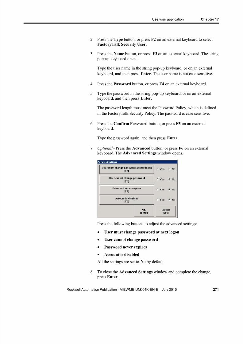
8/15/2019 Factory Talk View ME
http://slidepdf.com/reader/full/factory-talk-view-me 271/635
Use your application Chapter 17
Rockwell Automation Publication - VIEWME-UM004K-EN-E – July 2015 271
2. Press the Type button, or press F2 on an external keyboard to selectFactoryTalk Security User.
3. Press the Name button, or press F3 on an external keyboard. The string
pop-up keyboard opens.
Type the user name in the string pop-up keyboard, or on an externalkeyboard, and then press Enter . The user name is not case sensitive.
4. Press the Password button, or press F4 on an external keyboard.
5. Type the password in the string pop-up keyboard, or on an externalkeyboard, and then press Enter .
The password length must meet the Password Policy, which is definedin the FactoryTalk Security Policy. The password is case sensitive.
6. Press the Confirm Password button, or press F5 on an externalkeyboard.
Type the password again, and then press Enter .
7. Optional - Press the Advanced button, or press F6 on an externalkeyboard. The Advanced Settings window opens.
Press the following buttons to adjust the advanced settings:
User must change password at next logon
User cannot change password
Password never expires
Account is disabled
All the settings are set to No by default.
8. To close the Advanced Settings window and complete the change, press Enter .

8/15/2019 Factory Talk View ME
http://slidepdf.com/reader/full/factory-talk-view-me 272/635
Chapter 17 Use your application
272 Rockwell Automation Publication - VIEWME-UM004K-EN-E – July 2015
9. To close the Add User/Group Account window, press Cancel .
To add a Windows-linked user or group
1. Press the Add User/Group button to open the Add User/GroupAccount dialog box.
2. Press the Type button, or press F2 on an external keyboard to selectWindows-linked User , or Windows-linked User Group.
When adding a Windows-linked user, or a Windows-linked user group,the system will verify whether the user or group exists in the Windowsdomain, Windows User Accounts. If the user or group does not exist inthe Windows domain, Windows User Accounts, it cannot be added.
3. Press the Name button, or press F3 on an external keyboard. The string pop-up keyboard opens.
Type the user name in the string pop-up keyboard, or on an externalkeyboard, and then press Enter to save. The user name is not casesensitive.
Note: On the PanelView Plus 7 and PanelView Plus 6 terminals,there is a five-minute threshold when adding a Windows-linkeduser, or a Windows-linked user group.When you add a Windows-linked user, or a Windows-linkeduser group for the first time, a window prompts you to enter an
authorized user name and password.Within five minutes after a Windows-linked user, or aWindows-linked user group is successfully added, you canadd another Windows-linked user, or Windows-linked usergroup without entering an authorized user name andpassword.Beyond five minutes after a Windows-linked user, or aWindows-linked user group is successfully added, a windowwill prompt you to enter an authorized user name andpassword again before you can add another Windows-linkeduser, or Windows-linked user group.
4. To close the Add User/Group Account window, press Cancel .
The administrator can use the Delete User/Group button to delete aFactoryTalk security user, a Windows-linked user, or a Windows-linkedgroup from the current running application. It is not possible to delete aFactoryTalk Security group from the running application.
Delete a user orgroup
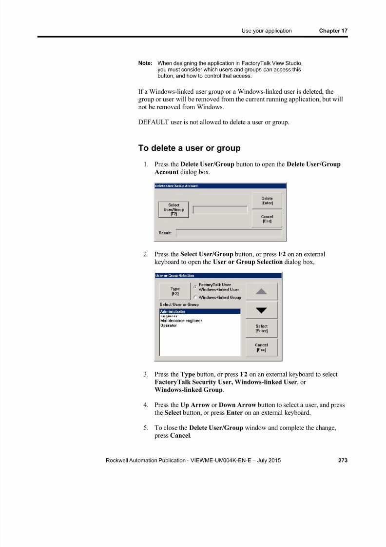
8/15/2019 Factory Talk View ME
http://slidepdf.com/reader/full/factory-talk-view-me 273/635
Use your application Chapter 17
Rockwell Automation Publication - VIEWME-UM004K-EN-E – July 2015 273
Note: When designing the application in FactoryTalk View Studio,you must consider which users and groups can access thisbutton, and how to control that access.
If a Windows-linked user group or a Windows-linked user is deleted, thegroup or user will be removed from the current running application, but willnot be removed from Windows.
DEFAULT user is not allowed to delete a user or group.
To delete a user or group
1. Press the Delete User/Group button to open the Delete User/GroupAccount dialog box.
2. Press the Select User/Group button, or press F2 on an externalkeyboard to open the User or Group Selection dialog box,
3. Press the Type button, or press F2 on an external keyboard to selectFactoryTalk Security User, Windows-linked User , orWindows-linked Group .
4. Press the Up Arrow or Down Arrow button to select a user, and pressthe Select button, or press Enter on an external keyboard.
5. To close the Delete User/Group window and complete the change, press Cancel .

8/15/2019 Factory Talk View ME
http://slidepdf.com/reader/full/factory-talk-view-me 274/635
Chapter 17 Use your application
274 Rockwell Automation Publication - VIEWME-UM004K-EN-E – July 2015
The administrator can use the Modify Group Membership button to changea FactoryTalk user, a Windows-linked user, or a Windows-linked groupmembership in the current running application.
Note: When designing the application in FactoryTalk View Studio,you must consider which users and groups can access thisbutton, and how to control that access.
If a user or group is added to a group, the user or group inherits theA-P security codes of the group.
If a user or group is removed from a group, the user or group no longerinherits the A-P security codes of that group.
If a user or group is a member of multiple FactoryTalk Securitygroups:
The user or group inherits the A-P security codes shared by the
multiple FactoryTalk Security groups. For example, if a user or group belongs to both Group One and Group Two; Group One has thesecurity codes of A, B, C, and Group Two has the security codes of B,C, D; and then the user or group only inherits the security codes of B,C.
When a user or group is removed from one FactoryTalk Securitygroup, the user or group is still a member of other FactoryTalk Securitygroups.
When a user or group is no longer a member of any FactoryTalkSecurity group, it is not possible for the user or group users to log in tothe running application.
To Modify group membership
1. Press the Modify Group Membership button to open the ModifyGroup Membership dialog box.
2. Press the Select User/Group button, or press F2 on an externalkeyboard to open the User or Group Selection dialog box.
Modify a user orgroup membership

8/15/2019 Factory Talk View ME
http://slidepdf.com/reader/full/factory-talk-view-me 275/635
Use your application Chapter 17
Rockwell Automation Publication - VIEWME-UM004K-EN-E – July 2015 275
3. Press the Type button, or press F2 on an external keyboard to selectFactoryTalk User, Windows-linked User , or Windows-linkedGroup .
4. Press the Up Arrow or Down Arrow button to select a user, and pressthe Select button, or press Enter on an external keyboard.
5. Press the FactoryTalk Group button to open FactoryTalk GroupSelection dialog box.
6. Press the Up Arrow or Down Arrow button to select a group, and press the Select button, or press Enter on an external keyboard.
7. To add the user or group to the selected FactoryTalk group, press Addto Group , or press F4 on an external keyboard.
To remove the user or group from the selected FactoryTalk group, press Remove from Group , or press F5 on an external keyboard.
The administrator can use the Unlock User Account button to unlock aFactoryTalk user account, which has been locked.
Note: When designing the application in FactoryTalk View Studio,you must consider which users and groups can access thisbutton, and how to control that access.
When a user account is locked, the user cannot log in the system.
If a FactoryTalk user exceeds incorrect password login attempts, the useraccount will be locked. When the user account is locked, the user cannot login to the system even with correct password before the user account isunlocked.
You cannot use this button to unlock a Windows-linked user. Only aWindows Domain administrator can unlock a Windows-linked user from adomain computer.
Unlock a user

8/15/2019 Factory Talk View ME
http://slidepdf.com/reader/full/factory-talk-view-me 276/635
Chapter 17 Use your application
276 Rockwell Automation Publication - VIEWME-UM004K-EN-E – July 2015
To unlock a user
1. Press the Unlock User Account button to open the Unlock UserAccount dialog box.
2. Press the Select User button, or press F2 on an external keyboard toopen the FactoryTalk User Selection dialog box.
3. Press the Up Arrow or Down Arrow button to select a user, and pressthe Select button, or press Enter on an external keyboard.
4. To close the Unlock User Account window and complete the change, press the Unlock button, or press Enter on an external keyboard.
The administrator can use the Disable User button to disable a FactoryTalk
user account from the current running application.
Note: When designing the application in FactoryTalk View Studio,you must consider which users and groups can access thisbutton, and how to control that access.
When a user account is disabled, the user cannot log in the system.
You cannot use this button to disable a Windows-linked user. Only aWindows Domain administrator can disable a Windows-linked user from adomain computer.
To disable a user
1. Press the Disable User button to open the Disable User Accountdialog box.
2. Press the Select User button, or press F2 on an external keyboard toopen the FactoryTalk User Selection dialog box.
Disable a user

8/15/2019 Factory Talk View ME
http://slidepdf.com/reader/full/factory-talk-view-me 277/635
Use your application Chapter 17
Rockwell Automation Publication - VIEWME-UM004K-EN-E – July 2015 277
3. Press the Up Arrow or Down Arrow button to select a user, and pressthe Select button, or press Enter on an external keyboard.
4. To close the Disable User Account window and complete the change,
press the Disable button, or press Enter on an external keyboard.
The administrator can use the Enable User button to enable a disabledFactoryTalk user account from the current running application.
Note: When designing the application in FactoryTalk View Studio,you must consider which users and groups can access thisbutton, and how to control that access.
When a disabled user is enabled, the user can log in the system again.
You cannot use this button to enable a Windows-linked user. Only aWindows Domain administrator can enable a Windows-linked user from adomain computer.
To enable a user
1. Press the Enable User button to open the Enable User Account dialog box.
2. Press the Select User button, or press F2 on an external keyboard toopen the FactoryTalk User Selection dialog box.
3. Press the Up Arrow or Down Arrow button to select a user, and pressthe Select button, or press Enter on an external keyboard.
4. To close the Enable User Account window and complete the change, press the Enable button, or press Enter on an external keyboard.
The administrator can use the Change User Properties button to modify aFactoryTalk user’s properties in the current running application.
Note: When designing the application in FactoryTalk View Studio,you must consider which users and groups can access thisbutton, and how to control that access.
To modify a user’s properties
1. Press the Change User Properties button to open the Change UserProperties dialog box.
2. Press the Select User button, or press F2 on an external keyboard toopen the FactoryTalk User Selection dialog box.
Enable a user
Change UserProperties

8/15/2019 Factory Talk View ME
http://slidepdf.com/reader/full/factory-talk-view-me 278/635
Chapter 17 Use your application
278 Rockwell Automation Publication - VIEWME-UM004K-EN-E – July 2015
3. Press the Up Arrow or Down Arrow button to select a user, and pressthe Select button, or press Enter on an external keyboard.
The FactoryTalk User Selection dialog box only shows the users
already configured in FactoryTalk Directory and packed in theapplication.
4. Press the following buttons to adjust the advanced settings:
User must change password at next logon
User cannot change password
Password never expires
Account is disabled
5. Press Change to save the changes.
The operator can enter or ramp numeric values at run time using the NumericInput Enable button or the numeric input cursor point.
When the operator presses the button or activates the cursor point, thenumeric pop-up keypad or scratchpad opens. If you set up the button orcursor point to ramp, pressing the object gives it focus, but does not open a
pop-up window.
To use the numeric pop-up scratchpad, a keyboard must be attached to theruntime computer, or the terminal must be a keypad terminal.
For information about setting up the Numeric Input Enable button andnumeric input cursor point, see Help.
You can also use a Ramp button to ramp numeric values. For details, seeHelp for the button.
Activate the cursor point
When the numeric input cursor point has focus, the operator can activate thecursor point by pressing any of these keys on the keyboard or keypad:
Numbers from 0 to 9
The minus sign ( - ) or decimal point ( . )
The Enter key, or an enter button
The Backspace key, or a backspace button
When the operator activates the numeric input cursor point, the numeric pop-up keypad or scratchpad opens.
Enter numericvalues
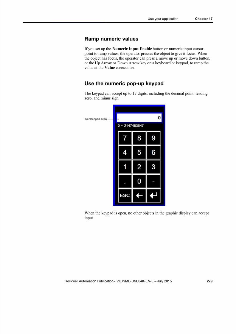
8/15/2019 Factory Talk View ME
http://slidepdf.com/reader/full/factory-talk-view-me 279/635
Use your application Chapter 17
Rockwell Automation Publication - VIEWME-UM004K-EN-E – July 2015 279
Ramp numeric values
If you set up the Numeric Input Enable button or numeric input cursor point to ramp values, the operator presses the object to give it focus. Whenthe object has focus, the operator can press a move up or move down button,or the Up Arrow or Down Arrow key on a keyboard or keypad, to ramp thevalue at the Value connection.
Use the numeric pop-up keypad
The keypad can accept up to 17 digits, including the decimal point, leadingzero, and minus sign.
When the keypad is open, no other objects in the graphic display can acceptinput.
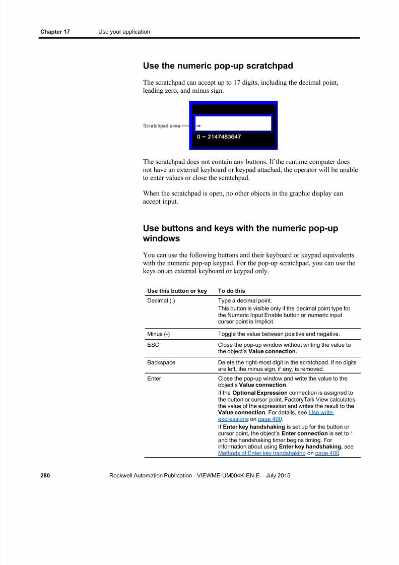
8/15/2019 Factory Talk View ME
http://slidepdf.com/reader/full/factory-talk-view-me 280/635
Chapter 17 Use your application
280 Rockwell Automation Publication - VIEWME-UM004K-EN-E – July 2015
Use the numeric pop-up scratchpad
The scratchpad can accept up to 17 digits, including the decimal point,leading zero, and minus sign.
The scratchpad does not contain any buttons. If the runtime computer doesnot have an external keyboard or keypad attached, the operator will be unableto enter values or close the scratchpad.
When the scratchpad is open, no other objects in the graphic display canaccept input.
Use buttons and keys with the numeric pop-upwindows
You can use the following buttons and their keyboard or keypad equivalentswith the numeric pop-up keypad. For the pop-up scratchpad, you can use thekeys on an external keyboard or keypad only.
Use this button or key To do thisDecimal (.) Type a decimal point.
This button is visible only if the decimal point type forthe Numeric Input Enable button or numeric inputcursor point is Implicit.
Minus (-) Toggle the value between positive and negative.
ESC Close the pop-up window without writing the value tothe object’s Value connection .
Backspace Delete the right-most digit in the scratchpad. If no digitsare left, the minus sign, if any, is removed.
Enter Close the pop-up window and write the value to the
object’s Value connection .If the Optional Expression connection is assigned tothe button or cursor point, FactoryTalk View calculatesthe value of the expression and writes the result to theValue connection . For details, see Use writeexpressions on page 490 . If Enter key handshaking is set up for the button orcursor point, the object’s Enter connection is set to 1and the handshaking timer begins timing. Forinformation about using Enter key handshaking , seeMethods of Enter key handshaking on page 400 .
8/15/2019 Factory Talk View ME
http://slidepdf.com/reader/full/factory-talk-view-me 281/635
Use your application Chapter 17
Rockwell Automation Publication - VIEWME-UM004K-EN-E – July 2015 281
Use this button or key To do this
Delete Clear the scratchpad.There is no Delete button in the pop-up keypad, but youcan use the Delete key on an external keyboard orkeypad.
How values are ramped
If the button or cursor point is being used to ramp a value at the Valueconnection:
When the tag assigned to the Value connection is an integer tag, but
the ramp value is a floating point value, the ramp value is added to (orsubtracted from) the Value connection value, and then the result isrounded and written to the Value connection.
For information about how values are rounded, see How values arerounded on page 98 .
If the operator presses and holds down the move up or move down button, or the Up Arrow or Down Arrow key on the keyboard orkeypad, the button or key goes into auto repeat mode. The ramp valueis added to (or subtracted from) the last value sent to the Valueconnection.
For more information about auto repeat mode, see To set up autorepeat for a button, use one of these methods on page 399 .
If ramping the button or cursor point would cause the value at theValue connection to exceed the maximum value, or be less than theminimum value, a message is written to the Diagnostics List and thevalue at the Value connection is not changed.
How values are calculated
When the pop-up keypad or scratchpad has focus and the operator presses the
Enter button, the value that is sent to the Value connection depends on howthe button or cursor point is set up.
The value the operator enters is compared to the minimum andmaximum range for the object. If the value is within the range, thevalue is written to the Value connection.
If the Optional Expression connection is assigned, and the originalvalue is within the range but the expression result is a value outside therange, the value is still written to the Value connection.

8/15/2019 Factory Talk View ME
http://slidepdf.com/reader/full/factory-talk-view-me 282/635
Chapter 17 Use your application
282 Rockwell Automation Publication - VIEWME-UM004K-EN-E – July 2015
If the decimal point type is Fixed Position, with a "Digits afterdecimal" value that is greater than 0, the decimal point is stripped fromthe value before comparing it to the minimum and maximum range.
For example, if the entered value is 9.25, the stripped value is 925.If the stripped value is within the range, the stripped value is sent to theValue connection (or substituted for the ? in the OptionalExpression ).
If the decimal point type is Implicit, and the tag assigned to the Valueconnection uses an integer data type, floating-point values are rounded.
If the Optional Expression connection is assigned, the floating-pointvalue is substituted for the ? in the expression, and the expressionresult is rounded.
For information about how values are rounded, see How values arerounded on page 98 .
Problems with the numeric pop-up windows
Problems with the numeric pop-up keypad and scratchpad occur under thesecircumstances:
If the graphic display changes remotely before the user has pressed theEnter button, the pop-up window closes without writing out a value.
If the screen resolution is smaller than 124 pixels wide by 240 pixelshigh, the pop-up keypad cannot open.
If the screen resolution is smaller than 124 pixels wide by 68 pixelshigh, the pop-up scratchpad cannot open.
If the value is too large for the data type of the tag assigned to theValue connection, the pop-up window remains open and the value isnot written to the connection. The scratchpad area changes to red toalert the operator of the error.
If the value is outside the minimum and maximum range specified forthe object, the pop-up window remains open and the value is notwritten to the connection. The scratchpad area changes to red to alertthe operator of the error.
If Enter key handshaking is still in effect, the pop-up window closes but the value is not written to the connection.
The operator can enter string values at run time using the String InputEnable button.
Enter string values
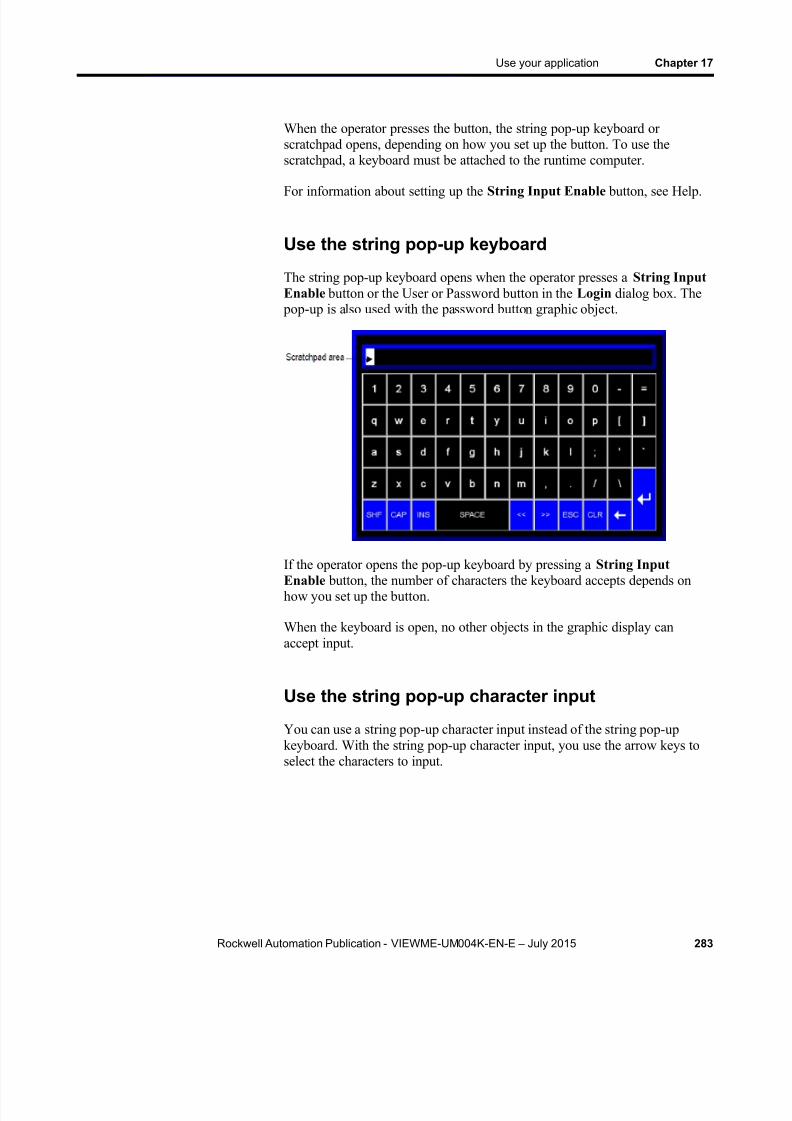
8/15/2019 Factory Talk View ME
http://slidepdf.com/reader/full/factory-talk-view-me 283/635
Use your application Chapter 17
Rockwell Automation Publication - VIEWME-UM004K-EN-E – July 2015 283
When the operator presses the button, the string pop-up keyboard orscratchpad opens, depending on how you set up the button. To use thescratchpad, a keyboard must be attached to the runtime computer.
For information about setting up the String Input Enable button, see Help.
Use the string pop-up keyboard
The string pop-up keyboard opens when the operator presses a String InputEnable button or the User or Password button in the Login dialog box. The
pop-up is also used with the password button graphic object.
If the operator opens the pop-up keyboard by pressing a String InputEnable button, the number of characters the keyboard accepts depends onhow you set up the button.
When the keyboard is open, no other objects in the graphic display canaccept input.
Use the string pop-up character input
You can use a string pop-up character input instead of the string pop-upkeyboard. With the string pop-up character input, you use the arrow keys to
select the characters to input.

8/15/2019 Factory Talk View ME
http://slidepdf.com/reader/full/factory-talk-view-me 284/635
Chapter 17 Use your application
284 Rockwell Automation Publication - VIEWME-UM004K-EN-E – July 2015
The string pop-up character input opens when the operator presses a StringInput Enable button or the User or Password button in the Login dialog
box. The pop-up is also used with the password button graphic object.
If the operator opens the string pop-up character input by pressing a StringInput Enable button, the number of characters the input accepts depends onhow you set up the button.
To use the s t r ing pop-up ch arac ter input on a person alcompute r
1. In FactoryTalk View Studio, from the Tools menu, select Options .
2. Click the String Pop-Up tab.
3. Select Use the string pop-up character input .
To use the s t r ing po p-up charac ter input on a PanelViewPlus 7, PanelView Plus 6, PanelView Plus , or PanelViewPlus CE terminal
1. In FactoryTalk View ME Station, click Terminal Settings.
2. Double-click Input Devices.
3. Select String Pop-Up , and then click Enter .
4. Specify whether to invoke the pop-up character input instead of the pop-up keyboard, and then click OK .
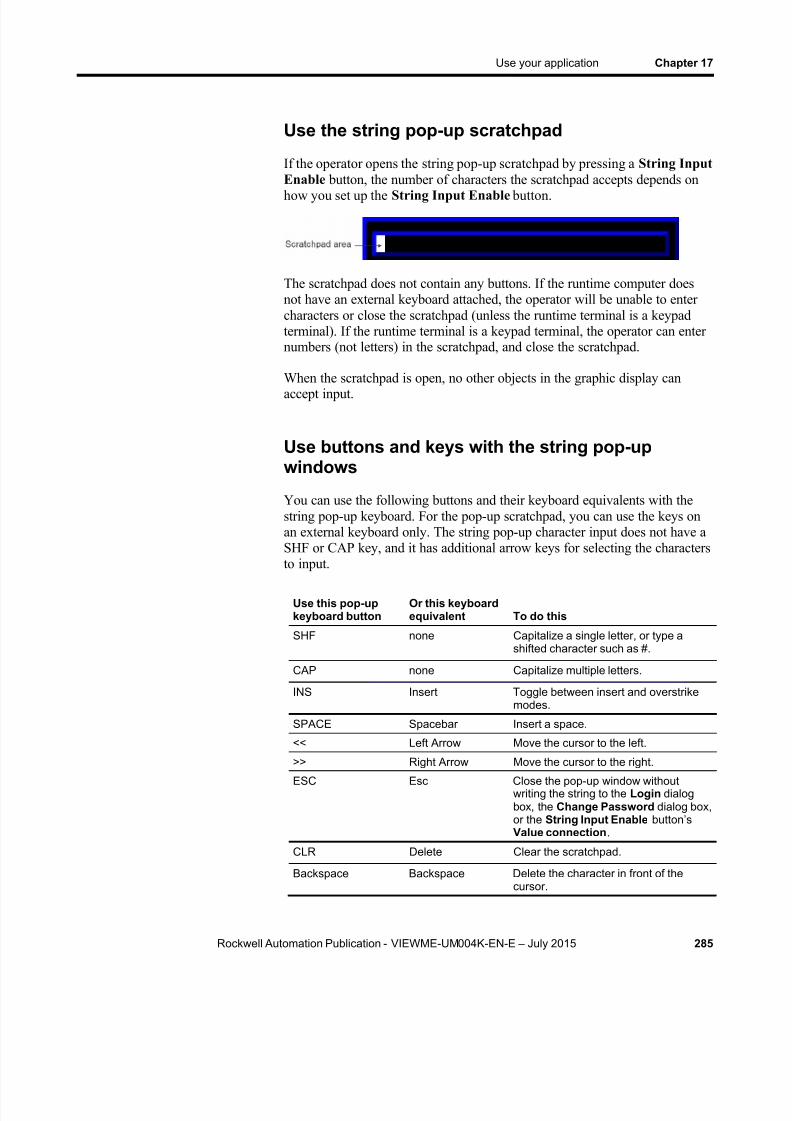
8/15/2019 Factory Talk View ME
http://slidepdf.com/reader/full/factory-talk-view-me 285/635
Use your application Chapter 17
Rockwell Automation Publication - VIEWME-UM004K-EN-E – July 2015 285
Use the string pop-up scratchpad
If the operator opens the string pop-up scratchpad by pressing a String InputEnable button, the number of characters the scratchpad accepts depends onhow you set up the String Input Enable button.
The scratchpad does not contain any buttons. If the runtime computer doesnot have an external keyboard attached, the operator will be unable to entercharacters or close the scratchpad (unless the runtime terminal is a keypadterminal). If the runtime terminal is a keypad terminal, the operator can enternumbers (not letters) in the scratchpad, and close the scratchpad.
When the scratchpad is open, no other objects in the graphic display canaccept input.
Use buttons and keys with the string pop-upwindows
You can use the following buttons and their keyboard equivalents with thestring pop-up keyboard. For the pop-up scratchpad, you can use the keys onan external keyboard only. The string pop-up character input does not have aSHF or CAP key, and it has additional arrow keys for selecting the charactersto input.
Use this pop-upkeyboard button
Or this keyboardequivalent To do this
SHF none Capitalize a single letter, or type ashifted character such as #.
CAP none Capitalize multiple letters.
INS Insert Toggle between insert and overstrikemodes.
SPACE Spacebar Insert a space.
<< Left Arrow Move the cursor to the left.
>> Right Arrow Move the cursor to the right.ESC Esc Close the pop-up window without
writing the string to the Login dialogbox, the Change Password dialog box,or the String Input Enable button’sValue connection .
CLR Delete Clear the scratchpad.
Backspace Backspace Delete the character in front of thecursor.

8/15/2019 Factory Talk View ME
http://slidepdf.com/reader/full/factory-talk-view-me 286/635
Chapter 17 Use your application
286 Rockwell Automation Publication - VIEWME-UM004K-EN-E – July 2015
Use this pop-upkeyboard button
Or this keyboardequivalent To do this
Enter Enter Close the pop-up window and write thestring to the Login dialog box, theChange Password dialog box, or theString Input Enable button’s Valueconnection .If Enter key handshaking is set up forthe String Input Enable button, thebutton’s Enter connection is set to 1and the handshaking timer beginstiming. For information about usingEnter key handshaking , see Methodsof Enter key handshaking on page 400 .
What is written to the Value connection
When the operator presses the Enter button in the pop-up keyboard orscratchpad, the string that is sent to the Value connection depends on howthe String Input Enable button is set up.
If a fill character is set up for the button, and the operator enters fewerthan the maximum number of input characters, the fill characters are
placed after the string the operator enters.
Spaces have a hex value of 20.
Zeroes have a hex value of 30.
FF characters have a hex value of FF.
Null characters have a hex value of 0. The null character indicatesthe end of string input. It does not add to the actual string length.
If the number of input characters is fewer than the number ofcharacters in the length of the string tag assigned to the Valueconnection , the remaining spaces are padded with the null character.
When the string is written to the Value connection , the first character is placed in the high order byte of the first word at the tag address, the second
character is placed in the low order byte of the first word, and so on.
Problems with the string pop-up windows
Problems with the string pop-up keyboard and scratchpad occur under thesecircumstances:
If the graphic display changes remotely before the user has pressed theEnter button, the pop-up window closes without writing out a string.

8/15/2019 Factory Talk View ME
http://slidepdf.com/reader/full/factory-talk-view-me 287/635
Use your application Chapter 17
Rockwell Automation Publication - VIEWME-UM004K-EN-E – July 2015 287
If the screen resolution is smaller than 236 pixels wide by 208 pixelshigh, the pop-up keyboard cannot open.
If the screen resolution is smaller than 236 pixels wide by 44 pixels
high, the pop-up scratchpad cannot open. If the string pop-up window is set up to accept more characters than the
Value connection tag length, the pop-up window remains open and thestring is not written to the connection. The scratchpad area changes tored to alert the operator of the error.
If Enter key handshaking is still in effect, the pop-up window closes but the value is not written to the connection.
This section gives an overview of the graphic objects you can use to changetag values. For information about setting up the objects, see Set up graphicobjects on page 389 and Help.
The operator uses these objects to start and stop plant operations, and tocontrol machines and processes. Choose the objects that best suit your
process. Set up the data source to carry out the desired actions in response tothe changes in tag values.
The operator can use function keys with all of these objects except controllist selectors, third-party ActiveX objects, and drawing objects with slideranimation. The last three types of objects can be pressed using a mouse ortouch screen.
For information about assigning function keys to graphic objects, see Assignfunction keys to buttons on page 393 .
Important: Do not use push buttons for emergency stops.Emergency stop buttons must be hard-wired.
You can also use macros to assign values to tags. For more information, seeUse macros on page 561 .
The operator can change tag values at run time using these graphic objects:
Use this graphic object To do this
Momentary push button Start a process or action by sending one value to the
tag when pressed, and another value when released.Maintained push button Toggle between two values by sending one value to the
tag when pressed, and a second value the next timethe button is pressed and released.This button is useful for changing a setting within amachine or process, but not for starting the machine orprocess.
Latched push button Start a machine or process and remain set (latched)until the process is completed, by sending a value tothe tag when pressed, and retaining this value untilreset (unlatched) by the Handshake connection.
Change tag values
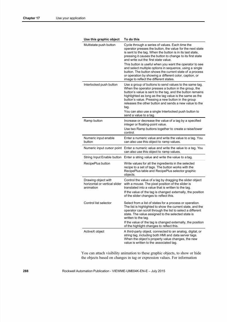
8/15/2019 Factory Talk View ME
http://slidepdf.com/reader/full/factory-talk-view-me 288/635
Chapter 17 Use your application
288 Rockwell Automation Publication - VIEWME-UM004K-EN-E – July 2015
Use this graphic object To do this
Multistate push button Cycle through a series of values. Each time theoperator presses the button, the value for the next stateis sent to the tag. When the button is in its last state,pressing it causes the button to change to its first stateand write out the first state value.This button is useful when you want the operator to seeand select multiple options in sequence, using a singlebutton. The button shows the current state of a processor operation by showing a different color, caption, orimage to reflect the different states.
Interlocked push button Use a group of buttons to send values to the same tag.When the operator presses a button in the group, thebutton’ s value is sent to the tag, and the button remainshighlighted as long as the tag value is the same as thebutton’s value. Pressing a new button in the groupreleases the other button and sends a new value to thetag.You can also use a single Interlocked push button tosend a value to a tag.
Ramp button Increase or decrease the value of a tag by a specifiedinteger or floating-point value.Use two Ramp buttons together to create a raise/lowercontrol.
Numeric input enablebutton
Enter a numeric value and write the value to a tag. Youcan also use this object to ramp values.
Numeric input cursor point Enter a numeric value and write the value to a tag. Youcan also use this object to ramp values.
String Input Enable button Enter a string value and write the value to a tag.
RecipePlus button Write values for all the ingredients in the selectedrecipe to a set of tags. The button works with theRecipePlus table and RecipePlus selector graphicobjects.
Drawing object withhorizontal or vertical slideranimation
Control the value of a tag by dragging the slider objectwith a mouse. The pixel position of the slider istranslated into a value that is written to the tag.If the value of the tag is changed externally, the positionof the slider changes to reflect this.
Control list selector Select from a list of states for a process or operation.The list is highlighted to show the current state, and theoperator can scroll through the list to select a differentstate. The value assigned to the selected state iswritten to the tag.If the value of the tag is changed externally, the positionof the highlight changes to reflect this.
ActiveX object A third-party object, connected to an analog, digital, orstring tag, including both HMI and data server tags.When the object’s property value changes, the newvalue is written to the associated tag.
You can attach visibility animation to these graphic objects, to show or hidethe objects based on changes in tag or expression values. For information

8/15/2019 Factory Talk View ME
http://slidepdf.com/reader/full/factory-talk-view-me 289/635
Use your application Chapter 17
Rockwell Automation Publication - VIEWME-UM004K-EN-E – July 2015 289
about visibility animation, see Set up the different types of animation on page464 .
For information about creating graphic objects, see Use graphic objects on
page 331 . For information about setting up graphic objects, see Set upgraphic objects on page 389 and Help.
This section gives an overview of the graphic objects you can use to showtag data. For information about setting up the objects, see Set up graphicobjects on page 389 and Help.
The operator can view tag data at run time using these graphic objects:
Use this graphic object To show this
Numeric display Numeric tag values. For example, show the currenttemperature of an oven.
Numeric input cursor point Numeric tag values. For example, show the currenttemperature of an oven.
String display String tag values. For example, set up the data sourceto generate strings that report on the state of a processor operation, or that provide the operator withinstructions about what to do next.
Bar graph Numeric values in bar graph format. The bar graphincreases or decreases in size to show the changingvalue.
Gauge Numeric values in dial format. The gauge’s needlemoves around the dial to show the changing value.
Multistate indicator The state of a process, on a panel that changes its
color, image, or caption to indicate the current state.Each state is set up to correspond to a numeric tagvalue or least significant bit.
Symbol The state of a process, using a monochrome image thatchanges color to indicate the current state. Each stateis set up to correspond to a numeric tag value or leastsignificant bit.This object is useful for showing the state of a processor operation at a glance.
List indicator The state of a process, using a list of possible stateswith the current state highlighted. Each state isrepresented by a caption in the list, and is set up tocorrespond to a numeric tag value or least significantbit.This indicator is useful if you want to view the currentstate but also want to see the other possible states. Forsequential processes, the list can alert the operatorabout what happens next in the process.
Trend Historical or current numeric tag values, plotted againsttime or shown i n an XY plot where one or more tags’values are plotted against another tag’s values to showthe relationship between them.
View tag data

8/15/2019 Factory Talk View ME
http://slidepdf.com/reader/full/factory-talk-view-me 290/635
Chapter 17 Use your application
290 Rockwell Automation Publication - VIEWME-UM004K-EN-E – July 2015
Use this graphic object To show this
RecipePlus table Current tag values and data set values of theingredients in the selected recipe, and the number ofingredients in the recipe. The table works with theRecipePlus button and RecipePlus selector graphicobjects.
Drawing object withrotation, width, height, fill,color, or horizontal orvertical position animation
Show the value of a tag using a pictorial representationthat shows the current value in relation to a range ofpossible values. For example, use rotation animation toshow the tag value as a needle’s position on a dial. For color animation, assign different colors to representdifferent values.
ActiveX object A third-party object, connected to an analog, digital, orstring tag, including both HMI and data server tags. Thedata shown depends on the object.
Many of these objects can be set up to manipulate tag values usingexpressions, and show the expression result rather than the original tag value.For information about expressions, see Use expressions on page 475 .
You can also attach visibility animation to these graphic objects, to show orhide the objects based on changes in tag or expression values. Forinformation about visibility animation, see Set up the different types ofanimation on page 464 .
For information about creating graphic objects, see Use graphic objects on page 331 . For information about setting up graphic objects, see Set upgraphic objects on page 389 or Help.
Show the date and time
To show the current date and time, create a time and date display. This objectuses the operating system’s date and time, in the format of the application’scurrent language, and therefore does not require tags or expressions.
The operator can view alarms and other messages at run time using thesegraphic objects and graphic displays:
This information Appears in thisobject In this default graphicdisplay For details, see
Alarm messages Alarm banner [ALARM]. The [ALARMBANNER] display onpage 145
Alarm messages Alarm list No default, although thisobject appears in the[ALARM MULTI-LINE] and[HISTORY] graphiclibraries.
The [ALARM] display on page 144 , The[ALARMMULTI-LINE] display on page 146 , and The[HISTORY] display onpage 148
View alarms andmessages
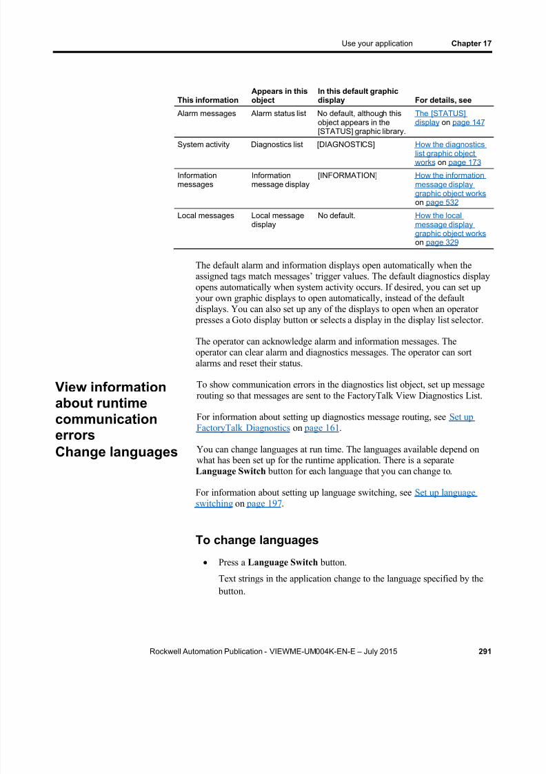
8/15/2019 Factory Talk View ME
http://slidepdf.com/reader/full/factory-talk-view-me 291/635
Use your application Chapter 17
Rockwell Automation Publication - VIEWME-UM004K-EN-E – July 2015 291
This informationAppears in thisobject
In this default graphicdisplay For details, see
Alarm messages Alarm status list No default, although thisobject appears in the
[STATUS] graphic library.
The [STATUS]display on page 147
System activity Diagnostics list [DIAGNOSTICS] How the diagnosticslist graphic objectworks on page 173
Informationmessages
Informationmessage display
[INFORMATION] How the informationmessage displaygraphic object works on page 532
Local messages Local messagedisplay
No default. How the localmessage displaygraphic object works on page 329
The default alarm and information displays open automatically when theassigned tags match messages’ trigger values. The default diagnostics displayopens automatically when system activity occurs. If desired, you can set upyour own graphic displays to open automatically, instead of the defaultdisplays. You can also set up any of the displays to open when an operator
presses a Goto display button or selects a display in the display list selector.
The operator can acknowledge alarm and information messages. Theoperator can clear alarm and diagnostics messages. The operator can sortalarms and reset their status.
To show communication errors in the diagnostics list object, set up message
routing so that messages are sent to the FactoryTalk View Diagnostics List.
For information about setting up diagnostics message routing, see Set upFactoryTalk Diagnostics on page 161 .
You can change languages at run time. The languages available depend onwhat has been set up for the runtime application. There is a separateLanguage Switch button for each language that you can change to.
For information about setting up language switching, see Set up languageswitching on page 197 .
To change languages
Press a Language Switch button.
Text strings in the application change to the language specified by the button.
View informationabout runtimecommunicationerrorsChange languages

8/15/2019 Factory Talk View ME
http://slidepdf.com/reader/full/factory-talk-view-me 292/635

8/15/2019 Factory Talk View ME
http://slidepdf.com/reader/full/factory-talk-view-me 293/635
Rockwell Automation Publication - VIEWME-UM004K-EN-E – July 2015 293
Chapter 18
Work with components
This chapter describes:
Which editors have components
Work with components
Print information in components
For information on working with particular editors, see the chapters later inthis guide.
With some editors you enter information in a single window or a tabbeddialog box. Other editors allow you to create multiple components, such asgraphic displays or message files. Each component is stored in a separatefile, with its own name.
You can create components in these editors:
Graphics (components include graphic displays, global objectdisplays, and graphic libraries, each in their own folder)
Parameters Local Messages
Information Messages
Data Log Models
Macros
RecipePlus
The Explorer window lists the components you create under the icon for theeditor you used to create the component.
You can use the Images editor to copy bitmap images into your application(but not to create new images). Each image you copy is listed as a componentunder the editor.
To view a list of components for an editor
Click the + symbol to the left of the editor icon, or double-click theeditor name.
Editors that havecomponents

8/15/2019 Factory Talk View ME
http://slidepdf.com/reader/full/factory-talk-view-me 294/635
Chapter 18 Work with components
294 Rockwell Automation Publication - VIEWME-UM004K-EN-E – July 2015
This section describes how to perform basic operations that are common toall components.
For information on working with components in particular editors, see the
chapters later in this guide.
Create components
To create a new com pon ent , do on e of the fo l lowing
Drag the component icon into the workspace.
Right-click the editor, and then click New .
From the File menu, select New , and then click the type of component
to create.
Open components
To open a comp onen t , do on e o f t he fo l lowing
Double-click the component.
Right-click the component, and then select Open .
Drag the component from the Explorer window to the workspace.
Save components
The Save tool is available when the active component contains unsavedchanges.
To save a compo nent
1. From the File menu, select Save , or click the Save tool.
2. If this is the first time you’re saving the component, type a name in theComponent name box, and then click OK .
Work withcomponents

8/15/2019 Factory Talk View ME
http://slidepdf.com/reader/full/factory-talk-view-me 295/635
Work with components Chapter 18
Rockwell Automation Publication - VIEWME-UM004K-EN-E – July 2015 295
Close components
To c lose a compo nent
From the File menu, select Close , or click the Close button on thecomponent’s title bar.
Some components have a Close button that you can click toclose the component.
Before the component closes you are prompted to save unsavedchanges, if there are any.
Add components into an application
You can use the same components in more than one application by addingcomponents into an application.
For example, if you want to use the same graphic display in Application Aand Application B, create the display in Application A, then add the graphicdisplay component from Application A to Application B.
When you add the component into Application B, changes you make to thecomponent in Application B are not reflected in the component inApplication A.
All the language strings associated with the component in Application A arecopied into Application B. For example, if you add an information messagefile for which three sets of language strings have been defined, all three setsof strings are copied into Application B, regardless of which languages have
been set up for Application B. For more information about using multiplelanguages, see Set up language switching on page 197 .
To add a compo nen t f rom App l i ca t ion A in to App l i ca tion B
1. In Application B, right-click the type of editor that was used to createthe desired component.
For example, to add a graphic display component, right-click theDisplays icon in the Graphics folder.
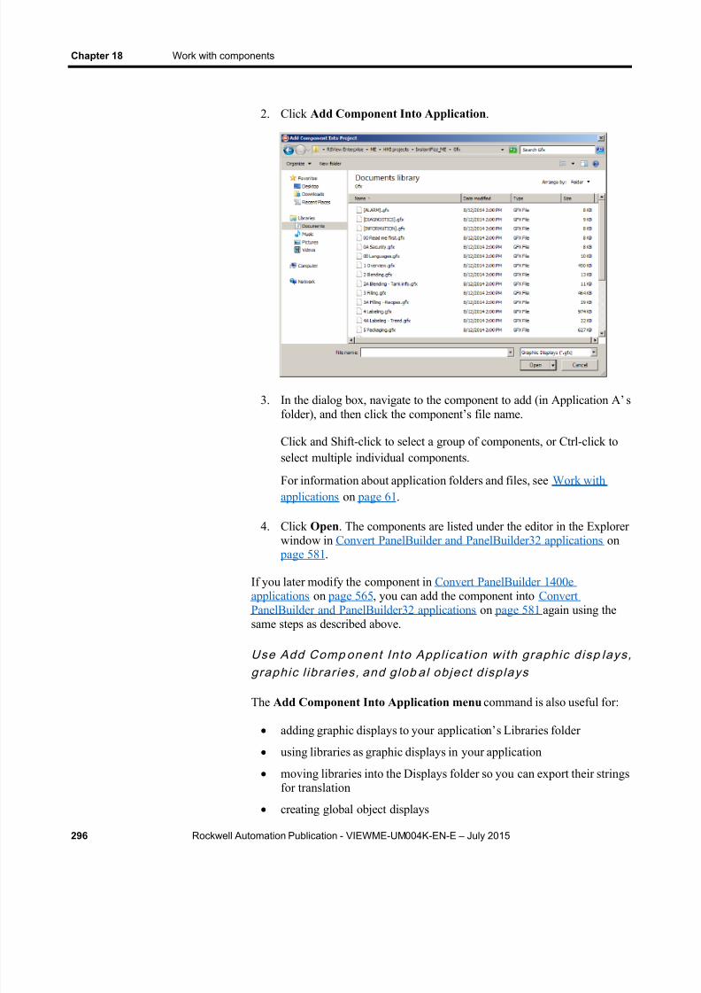
8/15/2019 Factory Talk View ME
http://slidepdf.com/reader/full/factory-talk-view-me 296/635
Chapter 18 Work with components
296 Rockwell Automation Publication - VIEWME-UM004K-EN-E – July 2015
2. Click Add Component Into Application .
3. In the dialog box, navigate to the component to add (in Application A’ sfolder), and then click the component’s file name.
Click and Shift-click to select a group of components, or Ctrl-click toselect multiple individual components.
For information about application folders and files, see Work withapplications on page 61 .
4. Click Open . The components are listed under the editor in the Explorerwindow in Convert PanelBuilder and PanelBuilder32 applications on
page 581 .
If you later modify the component in Convert PanelBuilder 1400eapplications on page 565 , you can add the component into ConvertPanelBuilder and PanelBuilder32 applications on page 581 again using thesame steps as described above.
Use Add Comp onent In to Appl ica t ion wi th graphic d isp lays ,graphic l ibrar ies , and g lob al objec t d isp lays
The Add Component Into Application menu command is also useful for:
adding graphic displays to your application’ s Libraries folder
using libraries as graphic displays in your application
moving libraries into the Displays folder so you can export their stringsfor translation
creating global object displays

8/15/2019 Factory Talk View ME
http://slidepdf.com/reader/full/factory-talk-view-me 297/635
Work with components Chapter 18
Rockwell Automation Publication - VIEWME-UM004K-EN-E – July 2015 297
For information about graphic libraries, see Use graphic libraries on page313 .
For information about global object displays, see Create global object
displays and base objects on page 510 .
Delete components
Deleting a component deletes it from the Explorer window and from thehard disk.
To dele te a compo nent
Right-click the component, and then select Delete .
Remove components
You can remove a component from the Explorer window but leave it on thehard disk, in case you want to use the component in another application.
To r emove a componen t
Right-click the component, and then select Remove .
Rename components
To rename a compo nent
1. Right-click the component, and then click Rename .
2. In the To box, type the new name.
3. Click OK .

8/15/2019 Factory Talk View ME
http://slidepdf.com/reader/full/factory-talk-view-me 298/635
Chapter 18 Work with components
298 Rockwell Automation Publication - VIEWME-UM004K-EN-E – July 2015
Duplicate components
The Duplicate option is useful for creating multiple similar components. Forexample, you could create a graphic display to use as a template, thenduplicate the display each time you want to use the template.
To dupl ica te a compo nent
1. Right-click the component, and then click Duplicate .
2. In the Component name box, type a name for the duplicatecomponent.
3. Click OK .
Print components
For information about selecting a printer and printing components, see Print on page 51 .

8/15/2019 Factory Talk View ME
http://slidepdf.com/reader/full/factory-talk-view-me 299/635
Rockwell Automation Publication - VIEWME-UM004K-EN-E – July 2015 299
Chapter 19
Use graphic displays
This chapter describes the Graphics , Images , and Local Messages editors inthe Graphics folder and outlines how to:
Use the Graphics editor
Set up graphic displays
Create a background for your displays
Use graphic libraries Import graphic images
Create local messages in your displays
Print graphic displays at run time
Before creating graphic displays, specify project settings. Project settingsdetermine important aspects of your graphic display such as size and
position. For more information, see About project settings on page 72 .
For information about global object displays and the Parameters editor, seeUse parameters and global objects on page 501 .
A graphic display represents the operator’s view of plant activity. Thedisplay can show system or process data and provide operators with a way towrite values to an external data source. The data source can be memory or adevice such as a programmable controller or an OPC server.
Operators can print the display at run time to create a visual record of tagvalues, object states, or current messages.
The elements that make up a graphic display are called graphic objects. Youcan create objects in the Graphics editor, or copy them from a global objectdisplay, from a graphic library, or from another application.
For information about creating and copying graphic objects, see Use graphicobjects on page 331 .
You can use up to 1,000 tags per graphic display. This limit includes the tagscontained in embedded variables.
PanelView Plus 7 Standard applications, and Compact Machine Editionapplications (applications running on PanelView Plus 6 Compact, orPanelView Plus Compact terminals) have a limited number of displays.
About graphicdisplays andgraphic objects

8/15/2019 Factory Talk View ME
http://slidepdf.com/reader/full/factory-talk-view-me 300/635
Chapter 19 Use graphic displays
300 Rockwell Automation Publication - VIEWME-UM004K-EN-E – July 2015
Before you begin, plan your displays. Think about what information theoperator needs to see, and the best way to provide the information. Forexample:
Does the operator need to know the exact speed of a conveyor belt, or just whether the belt is moving, jammed, or stopped?
Do different users need to have access to different types ofinformation?
Do you need to limit access to certain types of information?
Also consider the runtime environment and how the operator will use theapplication:
Does the runtime computer have a touch screen, mouse, keyboard, orsome combination of these?
How will the operator navigate through the displays of the application?
Will the application be available in multiple languages?
Review the chapters on planning, security, and navigation before you begincreating displays. Browse through the sample applications for design ideas.Map out a display hierarchy. Then create a graphic display to use as atemplate.
The time you spend planning your displays will make your application easyto use and will save you time in the long run.
For information about See
Plan your displays and creating a template Plan applications on page 53
Set up application security to control accessto displays
Set up security on page 175
Set up display navigation and creating adisplay hierarchy
Set up display navigation onpage 213
Set up how objects are used at run time Set up graphic objects on page389
TheGraphics
editor opens when you create or open a graphic display,global object display, or graphic library. Each display is stored in theDisplays folder. You can open and work on multiple graphic displays at thesame time.
Before you begin
Use the Graphicseditor

8/15/2019 Factory Talk View ME
http://slidepdf.com/reader/full/factory-talk-view-me 301/635
Use graphic displays Chapter 19
Rockwell Automation Publication - VIEWME-UM004K-EN-E – July 2015 301
Create and open graphic displays
To crea te a graphic d isplay
1. In the Graphics folder, do one of the following:
Right-click Displays and then click New .
Click the New Display tool .
Drag and drop the Displays icon into the workspace.
2. From the Edit menu, select Display Settings to open the DisplaySettings dialog box and specify settings for the display.
For more information, see Set up graphic displays on page 309 .
3. Create the objects you want to put in the display.
For information about creating graphic objects, see Use graphic objects on page 331 .
4. From the File menu, select Save , or click the Save tool .
5. In the Component name box, type a name for the display, and thenclick OK .
The display is added to the list in the Displays folder.
The display is created as a Replace display by default, but you canchange it to an On Top display in the Display Settings dialog box. Formore information about display types, see About display types on page310 .
To open a graphic d isplay
In the Graphics folder, open the Displays folder and then double-clickthe display name, or right-click the display name and then click Open .
You can also drag and drop the display from the Explorer window toan empty area in the FactoryTalk View Studio workspace.

8/15/2019 Factory Talk View ME
http://slidepdf.com/reader/full/factory-talk-view-me 302/635
Chapter 19 Use graphic displays
302 Rockwell Automation Publication - VIEWME-UM004K-EN-E – July 2015
This example shows a graphic display with the Explorer window closed.
The Graphics editor has special items on the View and Edit menus, andextra toolbars.
For details about using the Graphics editor, see Help.
Import and export graphic displaysEach graphic display’s information is contained in a file called
Displayname .gfx.
The Graphics Import Export Wizard in FactoryTalk View Studio allows youto export this information to an XML file, or to import a graphic displayXML file.
You can export the display information, import the graphic display XML fileto another FactoryTalk View application, and then modify it to suit yourrequirements. Or, you can modify the file before importing it.
You can use the Graphics Import Export Wizard to import graphic displayinformation that has been created using an external programming tool oreditor, or you can import a FactoryTalk View XML file.
For more information about importing and exporting graphic display files,see Import and export graphics XML files on page 613 .

8/15/2019 Factory Talk View ME
http://slidepdf.com/reader/full/factory-talk-view-me 303/635
Use graphic displays Chapter 19
Rockwell Automation Publication - VIEWME-UM004K-EN-E – July 2015 303
This section describes features of the Graphics editor that help you createyour displays. It describes how to:
Use context menus and toolbars to perform actions quickly.
View displays in grayscale to emulate the appearance of a PanelViewPlus terminal.
Set up a grid that you can use to position and size objects precisely.
Zoom in when you need to look at details closely.
Correct mistakes.
Test your displays as you work.
Use context menus
No matter where you are in the Graphics editor, you can open a menu byclicking the right mouse button. This is often quicker than moving the mouseup to the menus at the top of the screen.
Tools and tips forworking in theGraphics editor

8/15/2019 Factory Talk View ME
http://slidepdf.com/reader/full/factory-talk-view-me 304/635
Chapter 19 Use graphic displays
304 Rockwell Automation Publication - VIEWME-UM004K-EN-E – July 2015
The items on the menu depend on the cursor’s location. For example, whenyou right-click an object, the menu contains the most common actions youcan perform on that object.
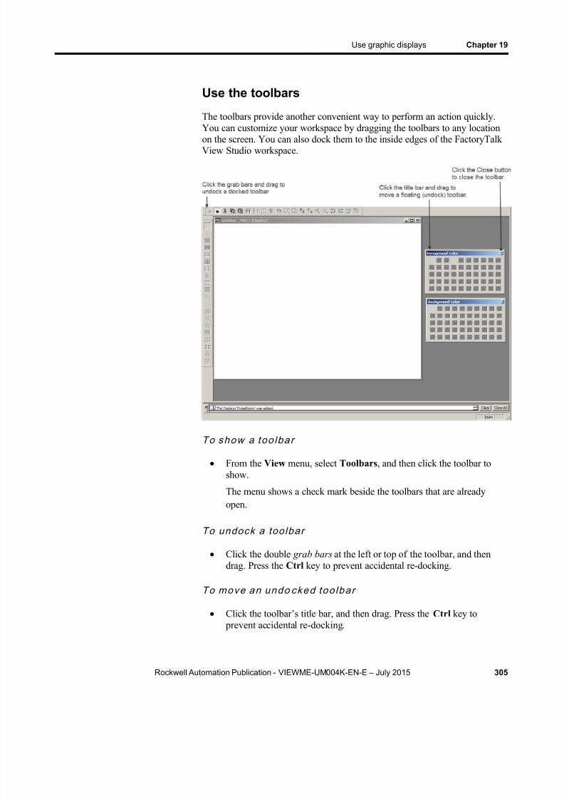
8/15/2019 Factory Talk View ME
http://slidepdf.com/reader/full/factory-talk-view-me 305/635
Use graphic displays Chapter 19
Rockwell Automation Publication - VIEWME-UM004K-EN-E – July 2015 305
Use the toolbars
The toolbars provide another convenient way to perform an action quickly.You can customize your workspace by dragging the toolbars to any locationon the screen. You can also dock them to the inside edges of the FactoryTalkView Studio workspace.
To show a too lba r
From the View menu, select Toolbars , and then click the toolbar toshow.
The menu shows a check mark beside the toolbars that are alreadyopen.
To undock a toolbar
Click the double grab bars at the left or top of the toolbar, and thendrag. Press the Ctrl key to prevent accidental re-docking.
To move an undo cked too lba r
Click the toolbar’s title bar, and then drag. Press the Ctrl key to prevent accidental re-docking.

8/15/2019 Factory Talk View ME
http://slidepdf.com/reader/full/factory-talk-view-me 306/635
Chapter 19 Use graphic displays
306 Rockwell Automation Publication - VIEWME-UM004K-EN-E – July 2015
To dock a toolb ar
Click the toolbar’s title bar, and then drag to any edge of theworkspace.
To c lose a toolbar
From the View menu, select Toolbars , and then click the name of thetoolbar to close, or click the toolbar’s Close button.
Show displays in grayscale
You can set displays to appear in grayscale, especially for developingapplications that will run on the PanelView Plus grayscale terminals. When
Show Displays in Grayscale is checked (on the View menu), all opendisplays will change from full color to grayscale. When Show Displays inGrayscale is cleared, all open displays will appear in color.
Show Displays in Grayscale does not work in Test Application mode.
Third party ActiveX objects will not appear in grayscale if Show Displays inGrayscale is checked.
Use the grid
To size and position objects precisely, use the grid. You can change the gridsettings at any time during the drawing process.
The grid can be active or passive. When the grid is active, all the objects youdraw or position are pulled to the closest grid point. This makes it easy toalign and size objects. When the grid is passive, it is visible but does notaffect the position of your objects.
Make the grid passive to position an element between the grid lines. Makethe grid active, and the next object you draw or place is automatically alignedwith the grid. Making the grid active does not affect the placement ofexisting objects.
The grid is visible during application development only. It is not visible atrun time.

8/15/2019 Factory Talk View ME
http://slidepdf.com/reader/full/factory-talk-view-me 307/635
Use graphic displays Chapter 19
Rockwell Automation Publication - VIEWME-UM004K-EN-E – July 2015 307
To se t up the gr id
1. From the View menu, select Grid Settings , or right-click an emptyarea of the display and then click Grid Settings .
2. Specify the color and spacing of the grid points.
3. To turn on the grid, click Show Grid.
When the Grid Settings dialog box is not open you can turn the gridon by clicking Show Grid on the View menu.
4. To make the grid active, click Snap To Grid.
When the Grid Settings dialog box is not open you can make the gridactive by clicking Snap On on the View menu.
5. Click OK .
To make the gr id pass ive
In the Grid Settings dialog box, clear the Snap To Grid check box, orfrom the View menu select Snap On to toggle the option off.
There is no check mark beside the menu item when it is turned off.
To turn off the gr id
In the Grid Settings dialog box, clear the Show Grid check box, or
from the View menu, select Show Grid to toggle the option off.
Zoom in and out
To magnify or reduce your view of a graphic display, use Zoom In and ZoomOut. Zoom In magnifies objects; Zoom Out reduces magnification.

8/15/2019 Factory Talk View ME
http://slidepdf.com/reader/full/factory-talk-view-me 308/635
Chapter 19 Use graphic displays
308 Rockwell Automation Publication - VIEWME-UM004K-EN-E – July 2015
To zoom in on ob jec ts
1. Select the objects you want to zoom in on.
2. From the View menu, select Zoom In , or click the Zoom In tool .
To zoom ou t
From the View menu, select Zoom Out , or click the Zoom Out tool
.
Correct mistakes
If you change your mind about something you did, you can undo the action.If you change your mind again, you can redo the action.
You can undo and redo all the operations you performed since you last savedthe display, one operation at a time.
The operations you perform between opening and closing a dialog box aretreated as a single operation. Operations you perform in the Property Panel are treated as separate operations.
To undo an op erat ion
From the Edit menu, click Undo , or click the Undo tool .
To redo an opera t ion
From the Edit menu, select Redo , or click the Redo tool .
Test your displays as you work
To test the objects in your displays as you work, use the Test Display tool toswitch to test mode. When you are finished testing, switch back to edit modeto continue editing.
8/15/2019 Factory Talk View ME
http://slidepdf.com/reader/full/factory-talk-view-me 309/635
Use graphic displays Chapter 19
Rockwell Automation Publication - VIEWME-UM004K-EN-E – July 2015 309
Note: Test mode is not the same as running the display. It does notchange the appearance or position of the display as set up inthe Display Settings dialog box. Alarm and informationmessages are not shown, although if communications are setup, tag values are read and written. Display navigation, datalogging, and macros do not work in this mode. If you want totest these features, test the application as described on Testyour application on page 221 .
If you set up local messages and graphic objects to use multiple languages,the messages and objects are shown in the current application languageduring test mode.
Use the Diagno st ics Lis t wh en in tes t mode
The Diagnostics List shows messages about system activities when you testyour graphic displays. You can specify the types of messages to show in theDiagnostics List , move the list, resize it, and clear the messages in it.
For information about using the Diagnostics List , see The Diagnostics List on page 43 .
For information about specifying the types of messages to show in theDiagnostics List , see Show diagnostics messages during applicationdevelopment on page 165 .
To use tes t mode
From the View menu, select Test Display , or click the Test Displaytool .
To re turn to edi t mode
From the View menu, select Edit Display, or click the Edit Displaytool .
To set up a graphic display, specify its type, background color, and runtime behavior in the Display Settings dialog box. You can specify and edit thedisplay settings at any time while you work on your display.
Set up graphicdisplays

8/15/2019 Factory Talk View ME
http://slidepdf.com/reader/full/factory-talk-view-me 310/635
Chapter 19 Use graphic displays
310 Rockwell Automation Publication - VIEWME-UM004K-EN-E – July 2015
Specify display settings
To speci fy d isplay se t t ings
From the Edit menu, select Display Settings , or right-click an emptyarea of the display and then select Display Settings .
For details about the options in the Display Settings dialog box, see Help.
About display types
Replace d isplays
Replace is the default display type. Replace displays are full-sized displays.They use the project window size specified in the Project Settings editor.
For more information about the project window size, see Project window sizeand runtime screen resolution on page 72 .
At run time, you can have only one Replace display open at a time. When theoperator opens a Replace display, this is what happens:
The Replace display that was open closes.
On Top displays that do not use the Cannot Be Replaced option areclosed.
The new Replace display opens.
8/15/2019 Factory Talk View ME
http://slidepdf.com/reader/full/factory-talk-view-me 311/635
Use graphic displays Chapter 19
Rockwell Automation Publication - VIEWME-UM004K-EN-E – July 2015 311
On Top displays that use the Cannot Be Replaced option remain open,on top of the new Replace display.
If the operator attempts to open a Replace display that is already open (for
example, using a Goto display button to which the same display is assigned),the display does not close and FactoryTalk View sends an error message toFactoryTalk Diagnostics.
On Top displays
Use the On Top option to create pop-up displays that open on top of thecurrent Replace display. Usually, On Top displays are smaller than Replacedisplays, so the operator does not lose track of display navigation.
You can open multiple On Top displays. If more than one On Top display isopen, the display that has focus, or had the most recent focus, appears on top.
When an On Top display closes, the display that had the most recent focusappears on top.
Use the Cannot Be Replaced option if you want the On Top display toremain open when a new Replace display is opened.
On Top displays do not have a Close button in the title bar. Be sure to createa close button graphic object in On Top displays so the operator can closethem.
The operator cannot move an On Top display by dragging its title bar. The
runtime position of the display is fixed (according to the position settingsdefined for the display).
You can specify unique titles for On Top displays. You can use embeddedvariables in the title, and the title text can switch languages at run time.
Resize displays
The project window size is used for all Replace displays. If you change the project window size after you have designed any graphic displays, you havethe option of scaling graphic displays.
If you choose to scale graphic displays, all Replace and On Top displays areresized and the objects in them are scaled to fit the new size. You can alsospecify whether to scale the font size and border size of the graphic objects,and the size of graphic images in the Images folder.
If you choose not to scale displays when you change the project window size,Replace displays are resized, but any objects in the displays remain the samesize and in the same position as before. On Top displays are not resized.
8/15/2019 Factory Talk View ME
http://slidepdf.com/reader/full/factory-talk-view-me 312/635
Chapter 19 Use graphic displays
312 Rockwell Automation Publication - VIEWME-UM004K-EN-E – July 2015
For information about specifying the project window size, see Projectwindow size and runtime screen resolution on page 72 .
Change the d isplay area whi le wo rking
You can change the display area of a display while you’re working on it bydragging the border of the display area. For example, you might want tomake the display area smaller so you can see parts of two displays in order todrag and drop objects between them.
Changing the display area in this manner does not change the display size forReplace displays. For On Top displays that are sized with the Use CurrentSize option, dragging the border does resize the display.
Another way to arrange multiple displays while working on them is to usethe options on the Windows menu. For example, Tile Horizontal arranges allthe open displays with as much of the top part of each display showing as
possible.
You can create a background for your graphic display by converting graphicobjects to wallpaper. When objects are converted to wallpaper, they arelocked into position and become an unchanging background for the otherobjects in the display.
Convert objects that do not need to be animated or updated with tag valuescan significantly improve the runtime performance of a graphic display.
Objects that have been converted to wallpaper cannot be selected or edited
until you unlock the wallpaper. Also, animations attached to the wallpaperobjects are not in effect. However, animations are restored when you unlockthe wallpaper.
Similarly, any tags or expressions assigned to an object become inactivewhen the object is converted to wallpaper. Connections are restored if youunlock the wallpaper.
To manage a number of objects easily, group the objects, and then convertthe group to wallpaper.
To convert objects to wallpaper1. Select the objects to convert.
2. For information about selecting objects, see Select and deselect objects on page 355 .
3. From the Edit menu, select Wallpaper , and then click Convert toWallpaper.
Create abackground foryour display

8/15/2019 Factory Talk View ME
http://slidepdf.com/reader/full/factory-talk-view-me 313/635
Use graphic displays Chapter 19
Rockwell Automation Publication - VIEWME-UM004K-EN-E – July 2015 313
4. For a single object, you can right-click it and then select Convert toWallpaper .
To unlock the wallpaper
From the Edit menu, select Wallpaper , and then click Unlock AllWallpaper .
All objects in the graphic display are converted back to their originalstate.
There are two graphic libraries that are available, Symbol Factory andGraphics Library
FactoryTalk View Studio Graphics Library comes with a set of libraries,
contained in the Libraries folder. As with a public library, the graphicslibraries can provide you with source materials and reference information.
Each graphic library consists of a graphic display, with the file extension.gfx. The library displays contain graphic objects that you might find usefulin your own application. Many of the objects are preconfigured withanimation. For example, see the Conveyor parts library.
You can:
Look at the objects and displays to get ideas for your own application.
Drag and drop (or copy and paste) objects from the libraries into yourown displays.
For information about copying objects from a library into your graphicdisplay, see Copy objects on page 372 .
Use the objects as they are or change them to suit your needs.
Create your own libraries of objects.
Create libraries of displays that are translated into multiple languages.
Use libraries as displays in your application.
The Symbol Factory is a library of over 5,000 graphics for industrialautomation, including pumps, pipes, valves, tanks, mixers, motors, ducts,electrical symbols, flow meters, material handling, sensors, PLCs,transmitters, and ISA symbols.
To open Symbol Factory
Symbol Factory opens into a new window when launched, there are fourways to open Symbol Factory:
Use graphiclibraries
Work with SymbolFactory

8/15/2019 Factory Talk View ME
http://slidepdf.com/reader/full/factory-talk-view-me 314/635
Chapter 19 Use graphic displays
314 Rockwell Automation Publication - VIEWME-UM004K-EN-E – July 2015
From the Explorer , click on the Symbol Factory Object.
When the Objects menu is available, click on the Symbol Factorydrop down menu item.
When the Objects toolbar is available, click on the Symbol Factory
icon .
Clicking the Launch Symbol Factory button in the Image Browser .
To select a graphic:
1. Browse the Categories frame, clicking a category to see the symbols inthe right frame.
2. Click the graphic to select it for the Graphic Display.
If the graphic is to be used in this original state, it can be dragged anddropped into the Graphic Display.
Note: When View Studio is unlicensed and in Grace Period mode,the Symbol Factory library will be in demo mode and restrictedin the number and type of graphics available for use. Only alicensed View Studio can enable a fully licensed SymbolFactory library.
Manipulate the graphic:
With the graphic selected, it can be modified using Symbol Factory
1. Select Options on the menu.
2. Select Symbol Options from the drop down menu.
3. The Symbol Options dialog box allows the graphic to be modified inseveral ways. The orientation can be changed, it can be rotated, the fillcolor can be changed and applied to the graphic in different modes.
4. The Preview frame will show the changes made to the graphic.
5. When finished modifying, the graphic can be dragged and droppedfrom the Preview frame to the Graphic Display, or copied and pastedinto the Graphic Display.
Symbol Factory has its own Help file which explains operations withinSymbol Factory and its functions.
8/15/2019 Factory Talk View ME
http://slidepdf.com/reader/full/factory-talk-view-me 315/635
Use graphic displays Chapter 19
Rockwell Automation Publication - VIEWME-UM004K-EN-E – July 2015 315
For more information, click Help in the Symbol Factory
To open a graphic l ibrary
1. In the Explorer window, open the Graphics folder, and then open theLibraries folder.
2. Double-click the library name, or right-click it and then select Open .
Create graphic libraries
You can create a graphic library in the Libraries folder, or create a graphicdisplay in the Displays folder and then add the display to the Libraries folder.
To create a graph ic l ibrary
1. In the Graphics folder, right-click Libraries and then click New .
2. Create the objects you want to put in the library.
For information about creating graphic objects, see Use graphic objects on page 331 .
3. From the File menu select Save , or click the Save tool .
4. In the Component name box, type a name for the library, and then clickOK .
The library is added to the list in the Libraries folder.
You can also create a graphic display and then use Add Component IntoApplication to add the display to the Libraries folder.
To add a graphic d isplay to th e l ibrary
1. Create the graphic display.
2. In the Explorer window, in the Graphics folder, right-click theLibraries icon.
3. Click Add Component Into Application .
4. In the dialog box, navigate to the Gfx folder, and then click the .gfx filefor the display to use.
The Gfx folder is located in:
8/15/2019 Factory Talk View ME
http://slidepdf.com/reader/full/factory-talk-view-me 316/635
Chapter 19 Use graphic displays
316 Rockwell Automation Publication - VIEWME-UM004K-EN-E – July 2015
(Windows XP) C:\Documents and Settings\All Users\SharedDocuments\RSView Enterprise\ME\HMI projects\ Application
Name
(Windows Server 2012, Windows 8.1, Windows 8, Windows 7,and Windows Server 2008) C:\Users\Public\PublicDocuments\RSView Enterprise\ME\HMI projects\ Application
Name
where Application Name is the name of your application.
5. Click Open . The display is copied into the Libraries folder.
Use libraries as displays in your application
The graphic libraries are available on the development computer, but do notappear at run time. To use a library as a graphic display at run time, you mustadd the library into your application’s folder of graphic displays.
If the library does not contain strings for languages supported by the currentapplication, the undefined strings are shown with question marks (?).
To use a l ibrary as a d isp lay in you r appl ica t ion
1. In the Explorer window, in the Graphics folder, right-click theDisplays icon.
2. Click Add Component Into Application .3. In the dialog box, navigate to the Libraries folder, and then click the
.gfx file for the library to use.
The Libraries folder is located in:
(Windows XP) \Documents and Settings\All Users\SharedDocuments\RSView Enterprise\ME
(Windows Server 2012, Windows 8.1, Windows 8, Windows 7,and Windows Server 2008) \Users\Public\PublicDocuments\RSView Enterprise\ME
4. Click Open . The library is copied into the Displays folder.
Use libraries to store displays with multiplelanguages
The maximum number of languages an application can use is 40 duringdevelopment, and 20 at run time. Since the libraries are stored outside of theHMI project folder and are available to all applications, they do not have this

8/15/2019 Factory Talk View ME
http://slidepdf.com/reader/full/factory-talk-view-me 317/635
Use graphic displays Chapter 19
Rockwell Automation Publication - VIEWME-UM004K-EN-E – July 2015 317
limit. However, since they are not stored in the HMI project folder, youcannot export the strings in library displays for translation. Instead, export agraphic display for translation, import the translated strings, then add thedisplay into the library.
When you use a library display in your application, make sure you add toyour application the languages that you plan to use from the library.
To save a l ibrary d isplay w i th mu l t ip le languages
1. Create a graphic display.
2. Export the text for your application, which will include the text used inthe graphic display.
3. Translate the text strings into each desired language, saving the filewith a new name for each language.
4. Import the files for all the new languages.
5. Add the graphic display to the Libraries folder.
The library is created with the option Support Multiple Languagesselected (in the Display Settings dialog box).
For detailed information about importing and exporting to use multiplelanguages, see Set up language switching on page 197 .
To save a l ibrary d isplay w i th mo re than 40 langu ages
1. Create a display in one application, with up to 40 languages, and add itto the library, as described in the previous section.

8/15/2019 Factory Talk View ME
http://slidepdf.com/reader/full/factory-talk-view-me 318/635
Chapter 19 Use graphic displays
318 Rockwell Automation Publication - VIEWME-UM004K-EN-E – July 2015
2. Add the display into a new application, with up to 40 differentlanguages in the new application.
3. Export the text for your application, which will include the text used in
the graphic display.
4. Translate the text strings into each desired language, saving the filewith a new name for each language.
5. Import the files for the new languages.
6. Add the graphic display (with the same name as the display in step 1)to the Libraries folder.
The new languages are added to the library. Make sure the displaycontains the same objects as the original display. Otherwise the new
display will overwrite the previous display, and all the originallanguage strings will be undefined.
Wha t is show n
When you open a library that supports multiple languages, the strings areshown using the current application language, if available. If the library doesnot contain the current language, the strings are shown as single questionmarks. Similarly, if the library contains the language but not all the stringsare defined for the language, undefined strings are shown as single questionmarks.
For more information about using multiple languages with graphic libraries,see Set up language switching on page 197 .
Location of library components
The Libraries folder is located in:
(Windows XP) C:\Documents and Settings\All Users\SharedDocuments\RSView Enterprise\ME
(Windows Server 2012, Windows 8.1, Windows 8, Windows 7, andWindows Server 2008) C:\Users\Public\Public Documents\RSViewEnterprise\ME
If desired, you can specify a different directory in which to store librarycomponents. If you specify a different directory, FactoryTalk View savesgraphic libraries that you add or create in the new directory. Similarly, whenyou open a library component FactoryTalk View looks for the component inthe specified directory.

8/15/2019 Factory Talk View ME
http://slidepdf.com/reader/full/factory-talk-view-me 319/635
Use graphic displays Chapter 19
Rockwell Automation Publication - VIEWME-UM004K-EN-E – July 2015 319
If you specify a different directory but want to use the libraries that comewith FactoryTalk View, use My Computer or Windows Explorer to copy thelibrary component files into the directory you have specified, or else changethe path back to the default path when you want to open a FactoryTalk View
library component.
To speci fy a new p ath for graphic l ibrar ies
From the Tools menu, select Options .
For details about using the Options dialog box, see Help.
You can use these types of external graphic files in your graphic displays:
.bmp — bitmap images
.jpg — JPEG images
.png — PNG images
.dxf — AutoCAD files
.wmf — Windows metafiles
You import and place .dxf and .wmf files in your displays in one step. Onceimported, they are converted to drawing objects. For more information aboutusing these types of files in your displays, see Use .wmf and .dxf files on
page 352 .
Bitmap images that come with FactoryTalk ViewStudio
FactoryTalk View Studio comes with sets of bitmaps that are useful forillustrating graphic objects and displays:
Import images intoyour application

8/15/2019 Factory Talk View ME
http://slidepdf.com/reader/full/factory-talk-view-me 320/635
Chapter 19 Use graphic displays
320 Rockwell Automation Publication - VIEWME-UM004K-EN-E – July 2015
Arrows
DIN symbols
ISA symbols
Keyboard button symbols such as Enter and Page Up
Parts such as buttons, conveyors, pipes, tanks, and valves
The symbols and most of the arrows are monochrome (that is, use only twocolors, one for the line and one for the fill).
You can set up the line and fill colors for the monochrome images that youuse for your objects.
For color images, including JPEG images, you can specify whether to use agradient, transparent, or solid background fill. If you select the transparent
background fill style, the black portions of the image become transparent.
For detailed information about setting up objects, see Help.
Locat ion o f b i tmap f i les
The bitmap files that come with FactoryTalk View Studio are stored in thisdirectory:
(Windows XP) C:\Documents and Settings\All Users\SharedDocuments\RSView Enterprise\Images
(Windows Server 2012, Windows 8.1, Windows 8, Windows 7, andWindows Server 2008) C:\Users\Public\Public Documents\RSViewEnterprise\Images
The images are in folders called Arrows, DIN, ISA, ListKey, and Parts.
Import bitmap, PNG, and JPEG images
To use bitmap, PNG, and JPEG images, you can:
Import the images first, and then place them in your displays as
needed. This method is useful for images that you use to illustrate yourdisplays.
For information about placing images in your display once you haveimported them, see To place a bitmap, PNG, or JPEG image in adisplay on page 345 .
Use the Image Browser to import images as needed while setting upyour graphic objects. This method is useful for images that you use aslabels on your graphic objects.
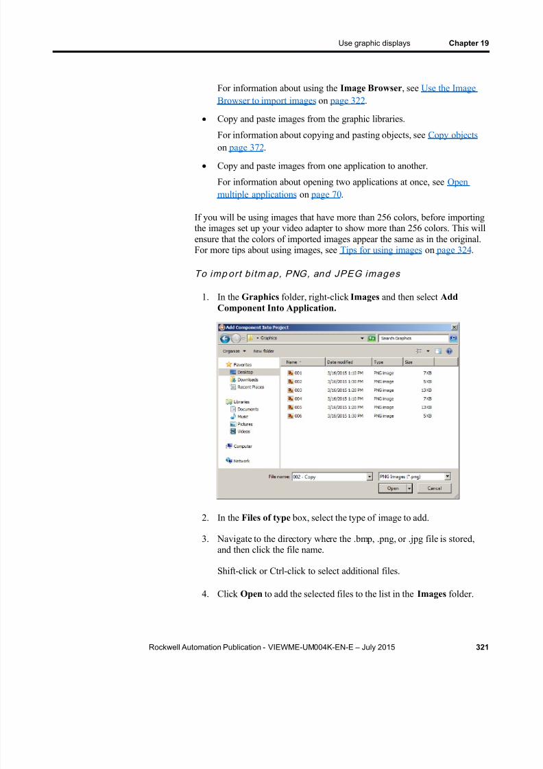
8/15/2019 Factory Talk View ME
http://slidepdf.com/reader/full/factory-talk-view-me 321/635
Use graphic displays Chapter 19
Rockwell Automation Publication - VIEWME-UM004K-EN-E – July 2015 321
For information about using the Image Browser , see Use the ImageBrowser to import images on page 322 .
Copy and paste images from the graphic libraries.
For information about copying and pasting objects, see Copy objects on page 372 .
Copy and paste images from one application to another.
For information about opening two applications at once, see Openmultiple applications on page 70 .
If you will be using images that have more than 256 colors, before importingthe images set up your video adapter to show more than 256 colors. This willensure that the colors of imported images appear the same as in the original.For more tips about using images, see Tips for using images on page 324 .
To imp or t b i tm ap, PNG, and JPEG images
1. In the Graphics folder, right-click Images and then select AddComponent Into Application.
2. In the Files of type box, select the type of image to add.
3. Navigate to the directory where the .bmp, .png, or .jpg file is stored,and then click the file name.
Shift-click or Ctrl-click to select additional files.
4. Click Open to add the selected files to the list in the Images folder.
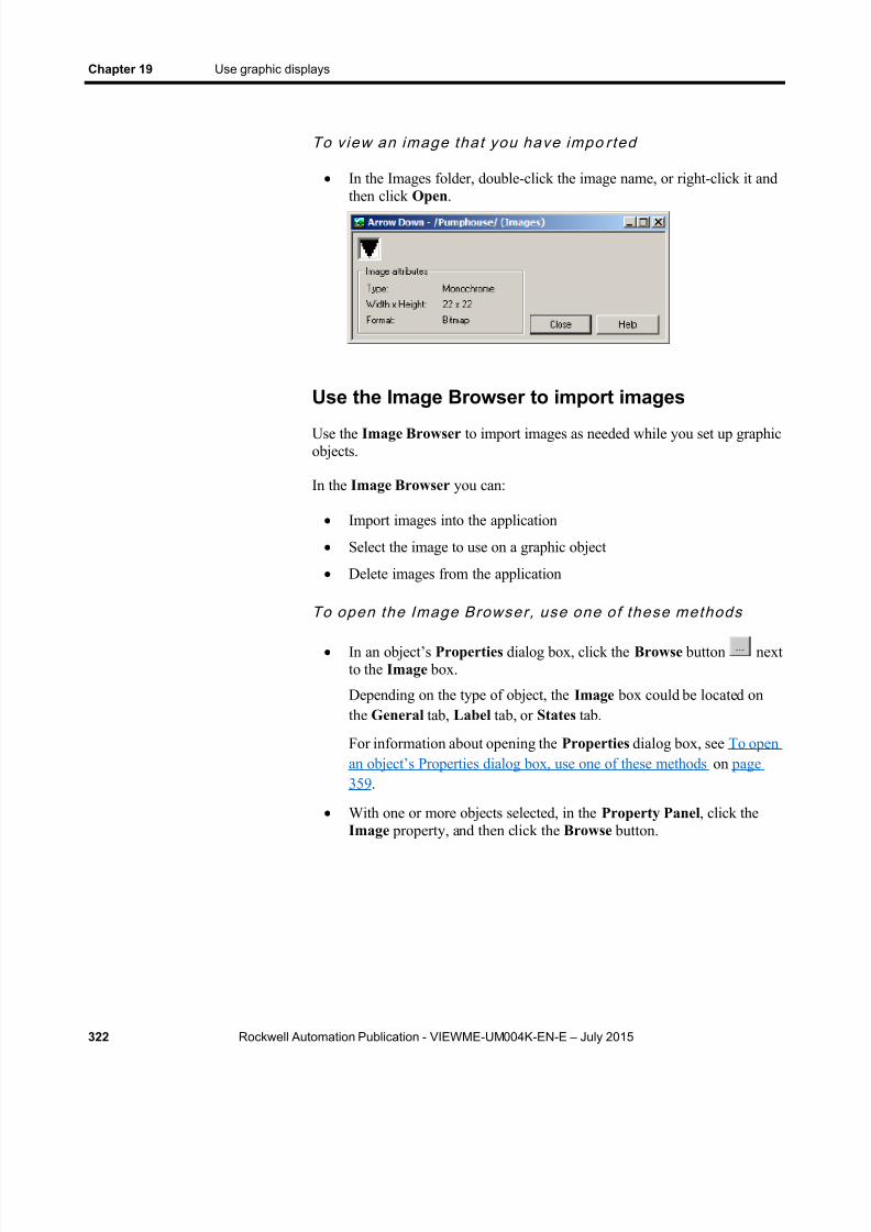
8/15/2019 Factory Talk View ME
http://slidepdf.com/reader/full/factory-talk-view-me 322/635
Chapter 19 Use graphic displays
322 Rockwell Automation Publication - VIEWME-UM004K-EN-E – July 2015
To view an image tha t you have impo r ted
In the Images folder, double-click the image name, or right-click it andthen click Open .
Use the Image Browser to import images
Use the Image Browser to import images as needed while you set up graphicobjects.
In the Image Browser you can:
Import images into the application
Select the image to use on a graphic object
Delete images from the application
To open the Image Browser, use one of these methods
In an object’s Properties dialog box, click the Browse button nextto the Image box.
Depending on the type of object, the Image box could be located onthe General tab, Label tab, or States tab.
For information about opening the Properties dialog box, see To openan object’s Properties dialog box, use one of these methods on page359 .
With one or more objects selected, in the Property Panel , click theImage property, and then click the Browse button.

8/15/2019 Factory Talk View ME
http://slidepdf.com/reader/full/factory-talk-view-me 323/635
Use graphic displays Chapter 19
Rockwell Automation Publication - VIEWME-UM004K-EN-E – July 2015 323
For information about opening the Property Panel , see Use theProperty Panel on page 360 .
For details about using the Image Browser to import, select, and deleteimages, see Help.
You can also remove an image by right-clicking it in the Images folder, andthen select Remove or Delete . For more information, see Removecomponents on page 297 .
Use Symbol Factory
Symbol Factory is a third-party graphics library that provides a large numberof quality graphic elements.
Imp or t Symb ol Factory ob jec ts d i rec t ly in to imageconta iner
1. From the Image Browser window, click the Launch Library… button. This will open a Symbol Factory window.
2. Browse through the Categories and locate the graphic to be used.
Select the graphic so it is highlighted. Click the Copy button inSymbol Factory. Symbol Factory will be minimized to the system tray.
3. From the Image Browser , click the Paste from Library button.
4. A dialog box will open and ask for a unique image name. Type the newname over the default text SFBitmap1 .
5. Click the OK button in the Image name dialog box. The dialog boxwill close returning you to the Image Browser . The new image will beshown and the new image name shown in the image browser explorer.

8/15/2019 Factory Talk View ME
http://slidepdf.com/reader/full/factory-talk-view-me 324/635
Chapter 19 Use graphic displays
324 Rockwell Automation Publication - VIEWME-UM004K-EN-E – July 2015
6. Click the OK button in the Image Browser for the graphic to be placed in the current workspace.
Note that any Symbol Factory object, including Bitmap, DIB and metafile
can be pasted into Image Browser where it will be stored as a bitmap.
Imp or t Symb ol Factory ob jec ts d i rec t ly in to d isplay
1. Launch Symbol Factory either by using the Menu bar ( Objects >
Symbol Factory ), or from the Objects toolbar ( ).
2. Browse through the Categories and locate the graphic to be used.Select the graphic so it is highlighted. To place the object into thedisplay you could do one of the following:
Click the Copy button in Symbol Factory. Symbol Factory will beminimized to the system tray, then from the Menu bar, click Editand paste.
Click the object and hold down the mouse button while draggingthe object to where you want it placed on the display. Releasing themouse drops the object onto the display.
Tips for using images
Use bi tmaps versus JPEG images
When deciding whether to use a bitmap image or a JPEG image, considerthese points:
FactoryTalk View supports 256 color (grayscale) and 16 million colorJPEG images only. For all other color types, use bitmaps.
For large color images (16 million color, 320 x 240 pixels or larger),JPEG images load faster than bitmaps. In all other cases, bitmaps loadfaster than JPEGs.
Color JPEG images have a much smaller file size than the equivalent bitmap image, and therefore require less disk space at run time.
Guidel ines for us ing images
Images consume Windows resources, so when using graphic images use thelowest color depth possible.
The more colors you use, the more memory is consumed, and the longer theimage takes to load and show.

8/15/2019 Factory Talk View ME
http://slidepdf.com/reader/full/factory-talk-view-me 325/635
Use graphic displays Chapter 19
Rockwell Automation Publication - VIEWME-UM004K-EN-E – July 2015 325
This bitmap type Consumes this many bits per pixel
Monochrome 1
16 color 4
256 color 8 (1 byte)
64 K color 16 (2 bytes)
16 million color 24 (3 bytes)
For example, a 24-bit bitmap image that measures 800x600 pixels consumes1440 KB of memory. If the bitmap color depth is decreased to 256 colors, theimage might have minor color loss, but the new image uses only 480 KB ofmemory.
Use images with a similar pixel size to the size of the FactoryTalk Viewobject on which the image will be placed. FactoryTalk View resizes the
image to fit the object, but if you use an image that is much larger than theobject, the display will be slow to open at run time, due to the time requiredto resize the image.
Use local messages to give the operator ongoing information about the statusof devices and processes. For example, you might use local messages todescribe the status of a device whose condition cannot be shown graphicallywith complete accuracy.
The messages you create in the Local Messages editor are shown in localmessage display objects in graphic displays. You can use multiple localmessage display objects in your application, and link each object to adifferent file of messages. Or, you can use the same file of messages formultiple local message display objects.
Local messages versus information messages
Use local messages to give the operator information in a specific graphicdisplay while the display is open. To give the operator information no matterwhich display is open, use information messages.
For details about information messages, see Use information messages on page 525 .
Steps for setting up local messages
Follow these steps to set up local messages:
1. In the Local Messages editor, set up the messages and their triggervalues.
Use local messages
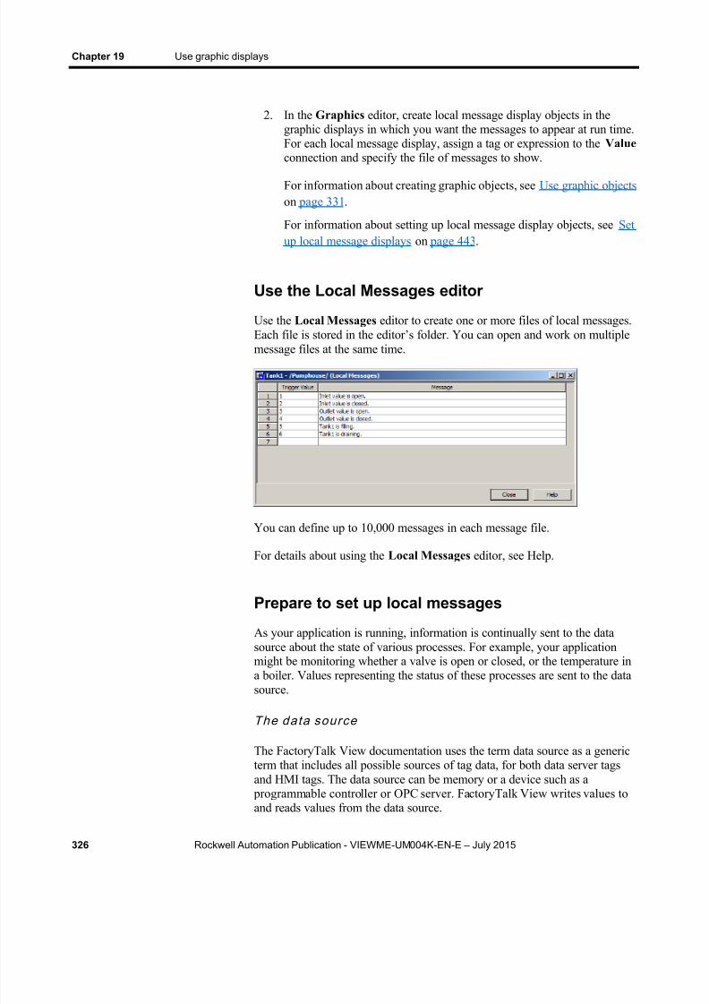
8/15/2019 Factory Talk View ME
http://slidepdf.com/reader/full/factory-talk-view-me 326/635
Chapter 19 Use graphic displays
326 Rockwell Automation Publication - VIEWME-UM004K-EN-E – July 2015
2. In the Graphics editor, create local message display objects in thegraphic displays in which you want the messages to appear at run time.For each local message display, assign a tag or expression to the Valueconnection and specify the file of messages to show.
For information about creating graphic objects, see Use graphic objects on page 331 .
For information about setting up local message display objects, see Setup local message displays on page 443 .
Use the Local Messages editor
Use the Local Messages editor to create one or more files of local messages.Each file is stored in the editor’s folder. You can open and work on multiplemessage files at the same time.
You can define up to 10,000 messages in each message file.
For details about using the Local Messages editor, see Help.
Prepare to set up local messages
As your application is running, information is continually sent to the datasource about the state of various processes. For example, your applicationmight be monitoring whether a valve is open or closed, or the temperature ina boiler. Values representing the status of these processes are sent to the datasource.
The data source
The FactoryTalk View documentation uses the term data source as a genericterm that includes all possible sources of tag data, for both data server tagsand HMI tags. The data source can be memory or a device such as a
programmable controller or OPC server. FactoryTalk View writes values toand reads values from the data source.

8/15/2019 Factory Talk View ME
http://slidepdf.com/reader/full/factory-talk-view-me 327/635
Use graphic displays Chapter 19
Rockwell Automation Publication - VIEWME-UM004K-EN-E – July 2015 327
The data source is set up to exchange information (in the form of numeric orstring values) between FactoryTalk View and the machine that yourapplication is controlling.
Ident i fy the tags and values to mo ni tor
To set up local messages, determine which tags associated with machine processes to monitor, and identify the values for those tags that will triggerlocal messages.
For information about creating HMI tags, see Use HMI tags on page 97 .
How local messages work
These are the key parts of the local message system: Local message files — text files containing lists of messages, with a
numeric trigger value for each message
Local message display object — a graphic object that shows localmessages when the Value connection assigned to the object matches amessage’s trigger value
Value connection — a tag or expression. When the value of thisconnection matches a message’s trigger value, the local messagedisplay object shows the associated message.
The local message display object always appears in the graphic display it’s placed in, whether or not there is a message to show. However, the operatordoes not see the message unless the object is located in the display theoperator is currently viewing.
Example : Show local messages
This example shows how to notify the operator of the status of a hoist. In theexample, the key parts of the local message system work together.
1. Create a tag called Hoist_Status . This tag points to an address in a programmable controller that is linked to sensors on the hoist. The tag
has five possible values:
The tag has thisvalue When the hoist has this status
1 At bottom
2 Raising
3 Stopped between the top and bottom
4 Lowering
5 At top

8/15/2019 Factory Talk View ME
http://slidepdf.com/reader/full/factory-talk-view-me 328/635
Chapter 19 Use graphic displays
328 Rockwell Automation Publication - VIEWME-UM004K-EN-E – July 2015
2. In the Local Messages editor, create these messages with triggervalues matching the values that will be sent to the Hoist_Status tag:
Trigger value Message
1 The hoist is ready to rise
2 The hoist is raising the pallet.
3 The hoist has stopped.
4 The hoist is lowering the pallet.
5 The hoist is finished rising.
Save the message file with the name Hoist status .
3. In the Graphics editor, create a local message display object. In theobject’s Properties dialog box, assign the Hoist_Status tag to theValue connection, and select the Hoist status message file.
At run time, when the operator views the graphic display containing the localmessage display object, the status of the hoist is shown.
Local messages and trigger values
Create messages associated with each tag value that you want to inform theoperator about. Assign each message a trigger value, and set up the datasource to send the trigger value to the Value connection. You can use bothHMI and data server tags
The trigger value can be any non-zero integer value (positive or negative).Trigger values do not need to be contiguous, but they must be unique foreach message. For example, you could use trigger values of 1, 2, and 3, orvalues of 10, 20, and 30.
If you use an analog tag or an expression, you can use any non-zero integeror floating point value to trigger an alarm. Floating point values are roundedto the nearest integer. For information about how values are rounded, seeHow values are rounded on page 98 .
Trigger values cannot be 0. Digital tags have two possible values, 0 and 1.Therefore, if you use a digital tag you can only use the value 1 to trigger amessage. If you want to use a digital tag to trigger two different messages,create an expression that adds 1 to the digital tag’s value. That way, you canuse the trigger values 1 and 2.
When the Value connection value is 0, the local message display object iscleared.

8/15/2019 Factory Talk View ME
http://slidepdf.com/reader/full/factory-talk-view-me 329/635
Use graphic displays Chapter 19
Rockwell Automation Publication - VIEWME-UM004K-EN-E – July 2015 329
Create local messages in multiple languages
FactoryTalk View 5.00 supports local messages in multiple languages. Whenyou create local messages, they are in the current application language. Youcan export the local messages for translation and then import them back intothe application. For details, see Set up language switching on page 197 .
Language sw i tching local messages in FactoryTalk ViewME Station 4.00
For applications that will run in FactoryTalk View ME Station version 4.00,use the CurrentLanguage( ) expression function to specify message offsets inthe local message file. In the file, divide your messages into sections for eachlanguage. For information about the CurrentLanguage( ) function, seeLanguage function on page 487 .
How the local message display graphic objectworks
When you open a graphic display at run time, FactoryTalk View reads thevalue of the Value connection and updates the local message display object
based on the value.
Wha t is show n
If the Value connection is unassigned, the display is filled withquestion marks (?).
The Value connection is rounded to the nearest integer. If the valuedoes not match any of the trigger values in the specified message file,the display is filled with question marks.
For information about how values are rounded, see How values arerounded on page 98 .
If the message is too long to fit in the object, the last shown character isreplaced with an asterisk (*).
When the Value connection ’s v alue is 0, the display is cleared.
If you set up local messages in multiple languages, messages areshown in the current application language. When a language switchoccurs, the message that was already in the local message displayremains in the language that it originally appeared in. New messagesare shown in the new language.
You can print your graphic displays on the development computer. Thismight be useful if you want other people to review the displays beforeimplementing the application, or if you want to keep a visual record of thedisplays.
Print displays

8/15/2019 Factory Talk View ME
http://slidepdf.com/reader/full/factory-talk-view-me 330/635
Chapter 19 Use graphic displays
330 Rockwell Automation Publication - VIEWME-UM004K-EN-E – July 2015
You can also print graphic displays at run time, to provide a printed record of process values such as trend data.
For information about printing on the development computer, see Print on
page 51 .
Print displays at run time
When you print a display at run time, everything on the screen is printed,including the current display, pop-up windows, and any visible backgroundapplications.
For information about specifying which printer to use at run time forapplications that will run on a personal computer, see Specify the printers touse at run time on page 238 .
For information about specifying printer options for applications that will runon a PanelView Plus 7, PanelView Plus 6, PanelView Plus, PanelView PlusCompact, or PanelView Plus CE terminal, see the PanelView Plus TerminalsUser Manual .
To pr in t graphic d isplays a t run t ime
Use one or both of these methods:
Create display print buttons in the graphic displays you want to print.At run time, the operator presses the buttons to print the displays.
For information about creating graphic objects, see Use graphic objects on page 331 .
Assign a tag or expression to the Remote Display Print connection (inthe Global Connections editor). When the value of the tag orexpression changes from 0 to a non-zero value, the current displays areautomatically printed.
Program the data source to trigger the change as often as you want thedata printed.
For more information about setting up remote display printing, see
Print displays on page 329 .

8/15/2019 Factory Talk View ME
http://slidepdf.com/reader/full/factory-talk-view-me 331/635
Rockwell Automation Publication - VIEWME-UM004K-EN-E – July 2015 331
Chapter 20
Use graphic objects
This chapter describes the types of graphic objects and outlines how to:
Create graphic objects, including drawing and ActiveX objects
Select and deselect objects and use the Object Explorer
Use the Properties dialog box and Property Panel to set up objects
Color and name objects
Test how objects look in different states
Assign tags and expressions to objects
Replace tags using tag substitution
Use tag placeholders
Move, copy, duplicate, resize, reshape, and delete objects
Group and ungroup objects, and edit group objects
Arrange objects and lock objects into position
For information about setting up graphic objects once you have created them,see Set up graphic objects on page 389 .
For information about setting up global objects, see Use parameters andglobal objects on page 501 .
For examples of how to set up objects, see the sample applications that comewith RSLinx Classic Studio. The Help also provides examples of how to useobjects.
The elements that make up a graphic display are called graphic objects. Useobjects to control your process, machines, and application.
FactoryTalk View comes with a complete range of configurable objects suchas push buttons, list selectors, bar graphs, and trends. Some objects interactwith the data source, allowing the operator to change or view tag values. Forexample, the operator can push a button to set a tag value to 1, causing a
programmable controller to start a conveyor belt. Other objects are used tocontrol your application. For example, there are button objects that you canuse to change displays and scroll through lists.
Types of graphicobjects
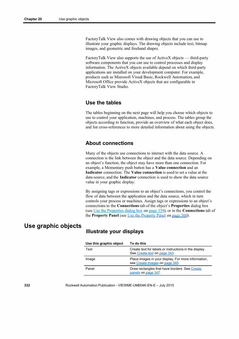
8/15/2019 Factory Talk View ME
http://slidepdf.com/reader/full/factory-talk-view-me 332/635
Chapter 20 Use graphic objects
332 Rockwell Automation Publication - VIEWME-UM004K-EN-E – July 2015
FactoryTalk View also comes with drawing objects that you can use toillustrate your graphic displays. The drawing objects include text, bitmapimages, and geometric and freehand shapes.
FactoryTalk View also supports the use of ActiveX objects — third-partysoftware components that you can use to control processes and displayinformation. The ActiveX objects available depend on which third-partyapplications are installed on your development computer. For example,
products such as Microsoft Visual Basic, Rockwell Automation, andMicrosoft Office provide ActiveX objects that are configurable inFactoryTalk View Studio.
Use the tables
The tables beginning on the next page will help you choose which objects touse to control your application, machines, and process. The tables group theobjects according to function, provide an overview of what each object does,and list cross-references to more detailed information about using the objects.
About connections
Many of the objects use connections to interact with the data source. Aconnection is the link between the object and the data source. Depending onan object’s function, the obje ct may have more than one connection. Forexample, a Momentary push button has a Value connection and an
Indicator connection. The Value connection is used to set a value at thedata source, and the Indicator connection is used to show the data sourcevalue in your graphic display.
By assigning tags or expressions to an object’s connections, you control theflow of data between the application and the data source, which in turncontrols your process or machines. Assign tags or expressions to an object’sconnections in the Connections tab of the object’s Properties dialog box(see Use the Properties dialog box on page 358 ), or in the Connections tab ofthe Property Panel (see Use the Property Panel on page 360 ).
Illustrate your displays
Use this graphic object To do this
Text Create text for labels or instructions in the display.See Create text on page 343 .
Image Place images in your display. For more information,see Create images on page 345 .
Panel Draw rectangles that have borders. See Createpanels on page 347 .
Use graphic objects
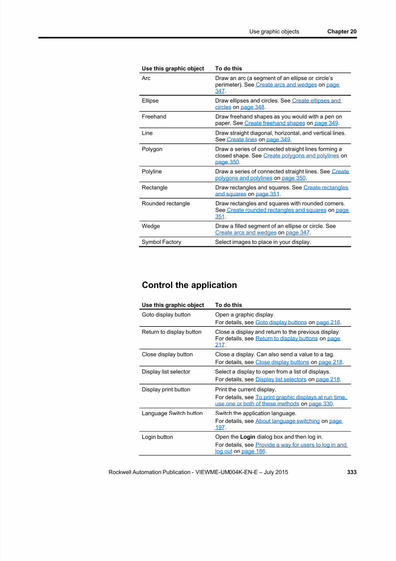
8/15/2019 Factory Talk View ME
http://slidepdf.com/reader/full/factory-talk-view-me 333/635
Use graphic objects Chapter 20
Rockwell Automation Publication - VIEWME-UM004K-EN-E – July 2015 333
Use this graphic object To do this
Arc Draw an arc (a segment of an ellipse or circle’sperimeter). See Create arcs and wedges on page347 .
Ellipse Draw ellipses and circles. See Create ellipses andcircles on page 348 .
Freehand Draw freehand shapes as you would with a pen onpaper. See Create freehand shapes on page 349 .
Line Draw straight diagonal, horizontal, and vertical lines.See Create lines on page 349 .
Polygon Draw a series of connected straight lines forming aclosed shape. See Create polygons and polylines onpage 350 .
Polyline Draw a series of connected straight lines. See Createpolygons and polylines on page 350 .
Rectangle Draw rectangles and squares. See Create rectanglesand squares on page 351 .
Rounded rectangle Draw rectangles and squares with rounded corners.See Create rounded rectangles and squares on page351 .
Wedge Draw a filled segment of an ellipse or circle. SeeCreate arcs and wedges on page 347 .
Symbol Factory Select images to place in your display.
Control the applicationUse this graphic object To do this
Goto display button Open a graphic display.For details, see Goto display buttons on page 216 .
Return to display button Close a display and return to the previous display.For details, see Return to display buttons on page217 .
Close display button Close a display. Can also send a value to a tag.For details, see Close display buttons on page 218 .
Display list selector Select a display to open from a list of displays.For details, see Display list selectors on page 218 .
Display print button Print the current display.For details, see To print graphic displays at run time,use one or both of these methods on page 330 .
Language Switch button Switch the application language.For details, see About language switching on page197 .
Login button Open the Login dialog box and then log in.For details, see Provide a way for users to log in andlog out on page 186 .

8/15/2019 Factory Talk View ME
http://slidepdf.com/reader/full/factory-talk-view-me 334/635
Chapter 20 Use graphic objects
334 Rockwell Automation Publication - VIEWME-UM004K-EN-E – July 2015
Use this graphic object To do this
Logout button Log out of the application.For details, see Log out on page 186 .
Password button Change the current user’s password, or any userpassword.For details, see Change passwords on page 267 .
Add User/Group button Add a FactoryTalk security user, a Windows-linkeduser, or a Windows-linked group to the currentrunning application.For details, see Add a user or group on page 270 .
Delete User/Group button Delete a FactoryTalk security user, a Windows-linkeduser, or a Windows-linked group from the currentrunning application.For details, see Delete a user or group on page 272 .
Modify Group Membershipbutton
Add a FactoryTalk user, a Windows-linked user, or aWindows-linked group to the current runningapplication, or remove from the application.For details, see Modify a user or group membership on page 274 .
Unlock User button Unlock a FactoryTalk user account, which has beenlocked from the current running application.For details, see Unlock a user on page 275 .
Enable User button Enable a disabled FactoryTalk user account from thecurrent running application.For details, see Enable a user on page 277 .
Disable User button Disable a FactoryTalk user account from the currentrunning application.For details, see Disable a user on page 276 .
Change User Propertiesbutton
Modify a FactoryTalk user’s properties in the currentrunning application.For details, see Change User Properties on page277 .
Shutdown button Stop the application and shut down FactoryTalk ViewME Station.For details, see Shutdown buttons on page 219 .
Goto configure modebutton
Stop the application and open the FactoryTalk ViewME Station dialog box.For details, see Goto configure mode buttons onpage 216 .
Print alarm history button Print a report of alarm messages in the alarm log file.You can print a report for all alarms, or for a specifiedalarm trigger.For details, see Set up Print Alarm History buttons onpage 446 .
Print alarm status button Print a report of the status of alarms, including howmany times each alarm was triggered and the time inalarm. You can print a report for all alarms, or for aspecified alarm trigger.For details, see Set up Print Alarm Status buttons onpage 447 .

8/15/2019 Factory Talk View ME
http://slidepdf.com/reader/full/factory-talk-view-me 335/635
Use graphic objects Chapter 20
Rockwell Automation Publication - VIEWME-UM004K-EN-E – July 2015 335
Start and control processes
Use this graphic object To do this
Momentary push button Start a process or action by sending one value to thetag when pressed, and another value when released.For details, see Set up Momentary push buttons onpage 407 .
Maintained push button Toggle between two values by sending one value tothe tag when pressed, and a second value the nexttime the button is pressed and released. This button isuseful for changing a setting within a machine orprocess, but not for starting the machine or process.For details, see Set up Maintained push buttons onpage 408 .
Latched push button Start a machine or process. The button remains set(latched) until the process is complete. For example,use this button to start a bag filling machine. When theprocess is complete (the bag is full), the button is reset(unlatched) by the Handshake connection.For details, see Set up Latched push buttons on page410 .
Multistate push button Cycle through a series of values. Each time theoperator presses the button, the value for the nextstate is sent to the tag. When the button is in its laststate, pressing it changes the button to its first stateand writes out the first state value.This button is useful when you want the operator tosee and select multiple options in sequence, using asingle button. The button shows the current state of anoperation by showing a different color, caption, orimage to reflect the different states.For details, see Set up Multistate push buttons onpage 412 .
Interlocked push button Use a group of buttons to send values to the same tag.When the operator presses one button in the group,the button’s value is sent to the tag, and the buttonremains highlighted as long as the tag value is thesame as the button’s value. Pressing another button inthe group releases the first button, and sends a newvalue to the tag.For details, see Set up Interlocked push buttons onpage 414 . You can also use a single Interlocked push button tosend a value to a tag.
Ramp button Increase or decrease the value of a tag by a specifiedinteger or floating-point value. For example, use twoRamp buttons together to create a raise/lower control.For details, see Set up Ramp buttons on page 415 .
Control list selector Select from a list of states for a process or operation.The list is highlighted to show the current state, andthe operator can scroll through the list to select adifferent state. The value assigned to the selectedstate is written to the tag.For details, see Set up control list selectors on page438 .
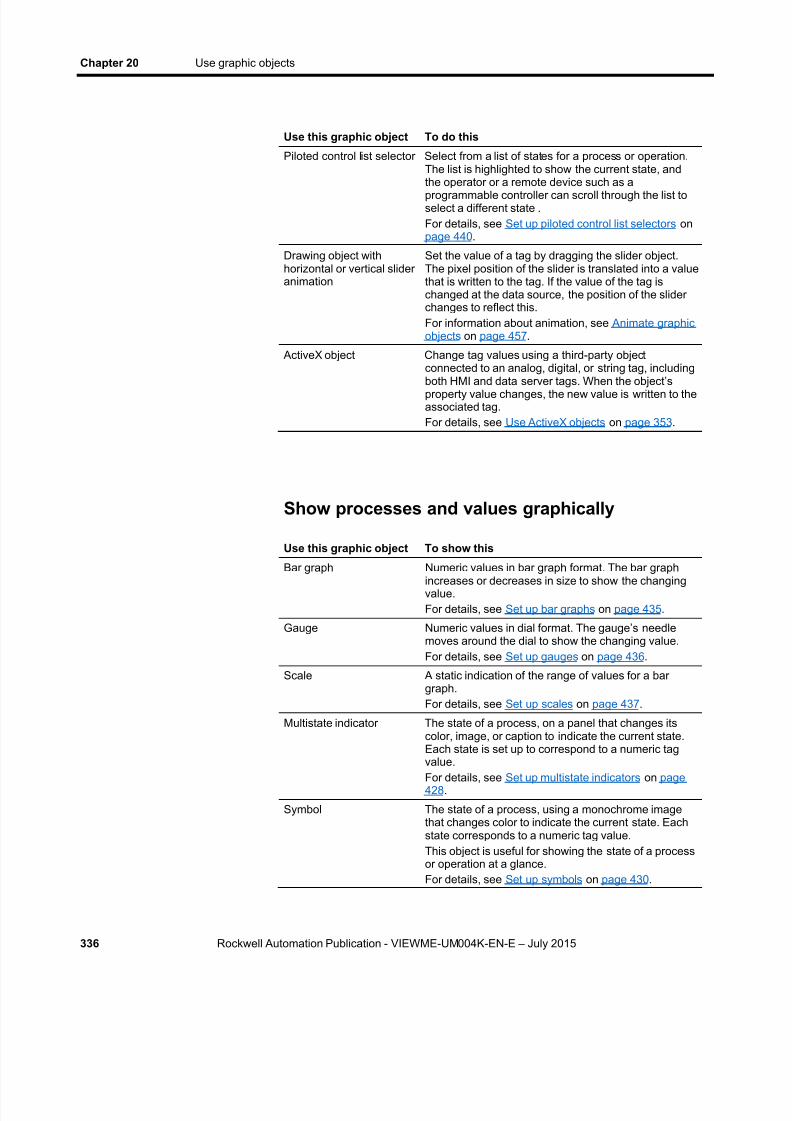
8/15/2019 Factory Talk View ME
http://slidepdf.com/reader/full/factory-talk-view-me 336/635
Chapter 20 Use graphic objects
336 Rockwell Automation Publication - VIEWME-UM004K-EN-E – July 2015
Use this graphic object To do this
Piloted control list selector Select from a list of states for a process or operation.The list is highlighted to show the current state, andthe operator or a remote device such as aprogrammable controller can scroll through the list toselect a different state .For details, see Set up piloted control list selectors onpage 440 .
Drawing object withhorizontal or vertical slideranimation
Set the value of a tag by dragging the slider object.The pixel position of the slider is translated into a valuethat is written to the tag. If the value of the tag ischanged at the data source, the position of the sliderchanges to reflect this.For information about animation, see Animate graphicobjects on page 457 .
ActiveX object Change tag values using a third-party objectconnected to an analog, digital, or string tag, including
both HMI and data server tags. When the object’sproperty value changes, the new value is written to theassociated tag.For details, see Use ActiveX objects on page 353 .
Show processes and values graphically
Use this graphic object To show this
Bar graph Numeric values in bar graph format. The bar graphincreases or decreases in size to show the changingvalue.For details, see Set up bar graphs on page 435 .
Gauge Numeric values in dial format. The gauge’s needlemoves around the dial to show the changing value.For details, see Set up gauges on page 436 .
Scale A static indication of the range of values for a bargraph.For details, see Set up scales on page 437 .
Multistate indicator The state of a process, on a panel that changes itscolor, image, or caption to indicate the current state.Each state is set up to correspond to a numeric tag
value.For details, see Set up multistate indicators on page428 .
Symbol The state of a process, using a monochrome imagethat changes color to indicate the current state. Eachstate corresponds to a numeric tag value.This object is useful for showing the state of a processor operation at a glance.For details, see Set up symbols on page 430 .

8/15/2019 Factory Talk View ME
http://slidepdf.com/reader/full/factory-talk-view-me 337/635
Use graphic objects Chapter 20
Rockwell Automation Publication - VIEWME-UM004K-EN-E – July 2015 337
Use this graphic object To show this
List indicator The state of a process, using a list of possible stateswith the current state highlighted. Each state isrepresented by a caption in the list, and correspondsto a numeric tag value.This indicator is useful if you want to view the currentstate, but also want to see the other possible states.For sequential processes, the list can alert theoperator about what happens next in the process.For details, see Set up list indicators on page 431 .
Trend Historical or current numeric tag values, plottedagainst time or shown in an XY plot (where one ormore tags’ values are plotted against another tag’svalues to show the relationship between them).For details, see Set up trends on page 535 .
Time and date display Display the current time and date.For details, see Set up time and date displays on page445 .
ActiveX object Data using a third-party object connected to an analog,digital, or string tag, including both HMI and dataserver tags. The format of the data shown depends onthe object.For details, see Use ActiveX objects on page 353 .
Drawing object withrotation, width, height, fill,color, or horizontal orvertical position animation
The value of a tag using a pictorial representation ofthe current value in relation to a range of possiblevalues. For example, use rotation animation to showthe tag value as a needle’s position on a dial. For color animation, assign different colors torepresent different values.For information about animation, see Animate graphic
objects on page 457 .
Work with lists, trends, alarm banners, andnumeric input objects
Use this buttonWith this graphicobject To do this
Pause button Trend Toggle a trend between pausing andautomatic scrolling.
Next pen button Trend Change the vertical axis labels for atrend to the scale for the next pen.
Backspace button Control list selectorPiloted control listselector
Move the cursor back to thehighlighted item in the list.
End button Lists and trends List — move to the bottom item in thelist.Trend — resume trend scrolling andmove to the current (latest) data in thetrend.

8/15/2019 Factory Talk View ME
http://slidepdf.com/reader/full/factory-talk-view-me 338/635
Chapter 20 Use graphic objects
338 Rockwell Automation Publication - VIEWME-UM004K-EN-E – July 2015
Use this buttonWith this graphicobject To do this
Enter button Lists Alarm list and alarm
banner
Select the item the cursor is pointingto.
Acknowledge the currently selectedalarm.
Home button Lists and trends List — move to the top item in the list.Trend — pause the trend and move tothe earliest data in the trend.
Move left / rightbuttons
Trend, Diagnosticslist
Trend — Pause the trend and scroll tothe left or right.Diagnostics list — scroll thediagnostic message content across thedisplay to view the full content.
Move up / downbuttons
Lists, trends, andnumeric inputobjects
List — move up or down one item inthe list.Trend — scroll up or down to showhigher or lower values on the verticalscale.Numeric input cursor point andNumeric Input Enable button — rampthe value up or down.
Page up / downbuttons
Lists Move up or down one page in the list.
Acknowledgealarm button
Alarm list Alarm banner
Acknowledge and silence the selectedalarm.
Alarm status modebutton
Alarm status list Change the type of alarms shown inthe alarm status list, from all alarms toactive alarms to past alarms.
Clear alarm bannerbutton Alarm banner Clear the alarm in the alarm bannerwithout removing the alarm from thealarm log file and alarm lists.
Diagnostics clearbutton
Diagnostics list Remove the selected message from alldiagnostics lists.
Informationacknowledgebutton
Information messagedisplay
Acknowledge the current message inthe display.
For more information about using the buttons with lists and trends:
For information about See
Link a button to a specific list,alarm banner, or trend object
Link buttons to objects on page 397
Use buttons with alarm lists, alarmbanners, and alarm status lists Use buttons with the alarm history and
alarm objects on page 154
Use buttons with informationmessage displays
Buttons in the [INFORMATION] display onpage 530
Use buttons with diagnostics lists Use buttons with the diagnostics list on page173

8/15/2019 Factory Talk View ME
http://slidepdf.com/reader/full/factory-talk-view-me 339/635
Use graphic objects Chapter 20
Rockwell Automation Publication - VIEWME-UM004K-EN-E – July 2015 339
For information about See
Use buttons with trends Use buttons to control the trend at run time on page 545
Unlike the buttons in the previous table, the following buttons do not workwith specific graphic objects. You can use them to work directly with alarmsin the alarm history and with the application’s diagnostics messages.
Use this button To do this
Acknowledge allalarms button
Acknowledge and silence all currently unacknowledgedalarms, or the alarms for a specific alarm trigger.
Clear alarm historybutton
Remove alarms from the alarm log file and all alarm lists.You can remove all alarms, or just the alarms for a specificalarm trigger. You can also reset the cleared alarms. Thisresets the number of times an alarm has been triggered to 0,
and the accumulated time in alarm to 0.Reset alarm statusbutton
Reset the number of times an alarm has been triggered to 0,and the accumulated time in alarm to 0, for all alarms.
Silence alarmsbutton
Silence the audio indicator for all current alarms (on personalcomputers only).
Sort alarms button Toggle between sorting alarms in alarm lists and the alarmlog file by time and by trigger value.
Diagnostics clear allbutton
Remove all diagnostics messages from all diagnostic lists.
Enter and show numeric and string values
Use this graphic object To do this
Numeric input enablebutton
Enter a numeric value and then write the value to a tagor an expression, or ramp a value at the data source.For details, see Set up Numeric Input Enable buttons on page 418 .
Numeric input cursor point Enter a numeric value and then write the value to a tagor an expression, or ramp a value at the data source.For details, see Set up numeric input cursor points onpage 420 .
String Input Enable button Enter a string value and then write the value to a tag.For details, see Set up String Input Enable buttons onpage 423 .
Numeric display Display numeric tag values. For example, show thecurrent temperature of an oven.For details, see Set up numeric displays on page 417 .

8/15/2019 Factory Talk View ME
http://slidepdf.com/reader/full/factory-talk-view-me 340/635
Chapter 20 Use graphic objects
340 Rockwell Automation Publication - VIEWME-UM004K-EN-E – July 2015
Use this graphic object To do this
String display Display string tag values. For example, set up the datasource to generate strings that report on the state of aprocess of operation, or that provide the operator withinstructions about what to do next.For details, see Set up string displays on page 422 .
RecipePlus button Display data set and tag values for ingredients in theRecipePlus table. Write tag values from the selecteddata set to the data source. Write tag values from thedata source to the selected data set or to a new dataset. Save data set values from the table to a recipe file.Rename or delete recipe units.For details, see RecipePlus button on page 549 .
RecipePlus selector Select the recipe unit to show, download from, write to,rename, or delete.For details, see RecipePlus selector on page 548 .
RecipePlus table Display and compare recipe data set values and tagvalues. Edit data set valuesFor details, see RecipePlus table on page 548 .
ActiveX object Enter or show data using a third-party objectconnected to an analog, digital, or string tag, includingboth HMI and data server tags. The format of the dataentered or shown depends on the object.For details, see Use ActiveX objects on page 353 .
Show alarms and messages
Use this graphic object To show this
Alarm list Multiple alarm messages, including the time the alarmsare triggered and acknowledged.For details, see How the alarm list graphic objectworks on page 150 .
Alarm banner A single unacknowledged alarm message.For details, see How the alarm banner graphic objectworks on page 152 .
Alarm status list The status of alarms, including how many times analarm has been triggered and how long it has beenactive.For details, see How the alarm status list graphicobject works on page 153 .
Diagnostics list Messages about system activity such as tag reads, tagwrites, and communications errors.For details, see How the diagnostics list graphic objectworks on page 173 .
Information messagedisplay
Messages about the process, prompts or instructions,and information about current states.For details, see The information message displaygraphic object on page 530 .

8/15/2019 Factory Talk View ME
http://slidepdf.com/reader/full/factory-talk-view-me 341/635
Use graphic objects Chapter 20
Rockwell Automation Publication - VIEWME-UM004K-EN-E – July 2015 341
Use this graphic object To show this
Local message display Ongoing information about the status of devices orprocesses.For details, see How the local message displaygraphic object works on page 329 .
The Objects menu in the Graphics editor contains items for creatingobjects, as well as items for selecting and rotating objects. You can alsocreate most objects using the tools on the Objects toolbar.
Before you can create an object, you must select the object’s tool, either byclicking a menu item or by clicking the tool on the toolbar. When you
position a cursor over a tool on the toolbar, the name of the tool is shown in atooltip and in the status bar.
To select a tool
Click the tool on the toolbar, or select the tool from the Objects menu.When you click a tool, the pointer changes to show which tool isactive.
Select tools forcreating graphicobjects

8/15/2019 Factory Talk View ME
http://slidepdf.com/reader/full/factory-talk-view-me 342/635
Chapter 20 Use graphic objects
342 Rockwell Automation Publication - VIEWME-UM004K-EN-E – July 2015
To deselect a tool, do one of the following
Double-click an empty area in the display.
Click the Select tool . Click another tool.
For some drawing objects, double-clicking an empty area of the displaycreates another instance of the object. For these objects, to finish drawing,click the Select tool. For more information, see Creating drawing objects on
page 343 .
To size and position objects precisely as you create them, use the grid.
To use the grid From the View menu, select Show Grid > Snap On .
For information about setting up the grid, see Use the grid on page 306 .
For information about setting up graphic objects once you have created them,see Set up graphic objects on page 389 .
For information about attaching animation to the objects you create, seeAnimate graphic objects on page 457 .
This section applies to graphic objects in general.
ActiveX objects and some drawing objects require extra steps to create them.For details about creating drawing objects, see the next section. Forinformation about ActiveX objects, see Use ActiveX objects on page 353 .
To create a graphic object
1. Select the tool for the object to create.
2. Click the mouse where you want to position the object, and then dragto draw a rectangle the general size you want the object to be.
3. Double-click the object to open its Properties dialog box.
4. In the dialog box, specify how the object looks, its behavior, andconnections. For more information about the Properties dialog box,see Use the Properties dialog box on page 358 .
Before you begincreating objects
Create graphicobjects
8/15/2019 Factory Talk View ME
http://slidepdf.com/reader/full/factory-talk-view-me 343/635
Use graphic objects Chapter 20
Rockwell Automation Publication - VIEWME-UM004K-EN-E – July 2015 343
You can also use the Property Panel to set up objects. For informationabout using the Property Panel , see Use the Property Panel on page360 .
The following instructions for creating drawing objects describe how tocreate the objects and then open the objects’ Properties dialog boxes to setup how the objects look. For information about using the Properties dialog
box, see Use the Properties dialog box on page 358 .
You can also use the Property Panel to set up objects. For information aboutusing the Property Panel , see Use the Property Panel on page 360 .
Create text
Choose fon t s
You can select any font you have installed, but TrueType and OpenTypefonts are recommended. These fonts can be resized easily, without losing textquality.
For PanelView Plus and PanelView Plus CE terminals, you must useTrueType fonts.
If you run an application on a computer that does not have the fonts you usedwhen setting up the application, Windows substitutes with the fonts that mostclosely match the fonts you specified.
Choose fonts for language swi tching
If you are going to use the application with multiple languages, werecommend using Microsoft Sans Serif or Tahoma. These fonts allow forfont linking to support the character sets of other languages. PanelView Plus7, PanelView Plus 6, PanelView Plus, PanelView Plus Compact, andPanelView Plus CE terminals are shipped with font linking turned on.
For more information about font linking, see Help. For more informationabout setting up languages for your application, see Set up languageswitching on page 197 .
Use the Size to f i t optio n
If you use the Size to fit option, the size of the text object will likely changefor different languages. Make sure you check all displays containingtranslated language strings.
Create drawingobjects
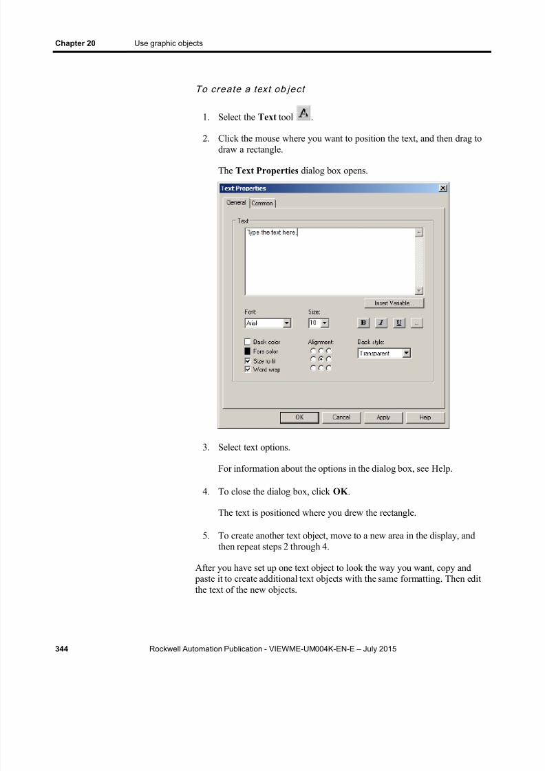
8/15/2019 Factory Talk View ME
http://slidepdf.com/reader/full/factory-talk-view-me 344/635
Chapter 20 Use graphic objects
344 Rockwell Automation Publication - VIEWME-UM004K-EN-E – July 2015
To create a text ob ject
1. Select the Text tool .
2. Click the mouse where you want to position the text, and then drag todraw a rectangle.
The Text Properties dialog box opens.
3. Select text options.
For information about the options in the dialog box, see Help.
4. To close the dialog box, click OK .
The text is positioned where you drew the rectangle.
5. To create another text object, move to a new area in the display, andthen repeat steps 2 through 4.
After you have set up one text object to look the way you want, copy and paste it to create additional text objects with the same formatting. Then editthe text of the new objects.

8/15/2019 Factory Talk View ME
http://slidepdf.com/reader/full/factory-talk-view-me 345/635
Use graphic objects Chapter 20
Rockwell Automation Publication - VIEWME-UM004K-EN-E – July 2015 345
To edi t a text objec t
1. Double-click the text.
The Text Properties dialog box opens.
2. In the Text box, click where you want to make the change. To deletetext characters, use the Backspace and Delete keys.
Create images
Use the image graphic object to place images in your graphic displays.Images support visibility animation only. You can use images alreadycontained in the Images folder or use Symbol Factory to select and add a
graphic to the display and the Images folder.
Use bitm aps, PNG, and JPEG imag es
Before you can place a bitmap, PNG, or JPEG image in a display, you mustimport the image into your application. For more information, see Import
bitmap, PNG, and JPEG images on page 320 .
To place a bi tmap, PNG, or JPEG imag e in a display
1. Select the Image tool .
2. Click the mouse where you want to position the image, and then dragto draw a rectangle.
The Image Browser opens.
3. In the Select image list, click the image to place, and then click OK .
8/15/2019 Factory Talk View ME
http://slidepdf.com/reader/full/factory-talk-view-me 346/635
Chapter 20 Use graphic objects
346 Rockwell Automation Publication - VIEWME-UM004K-EN-E – July 2015
For more information about using the Image Browser , see Use theImage Browser to import images on page 322 .
The image is placed where you drew the rectangle, but the actual size
of the image is used, rather than the size of the rectangle you drew.
4. To change the image’s attributes, double -click the image to open theImage Properties dialog box.
5. Select image options.
For information about the options in the dialog box, see Help.
6. Click OK to close the dialog box.
To add an image f rom Symbo l Factory to a graphic ob jec tus ing th e image brows er :
1. In the graphic display, draw the graphic object you are going to importan image for. The Image Browser will open.
2. In the Image Browser , click Launch Library... Symbol Factory willopen as a new window.
3. Browse the Categories frame, clicking on a category to see the symbolsin the right frame.
4. Click on the graphic to select it for the Graphic Display.
5. Click Copy , the Symbol Factory minimizes, returning to the ImageBrowser .
6. Click the Paste from Library button. A dialog box Image NameEntry will open.
7. Type in an unique name for the image, then click the OK button.
8. The graphic will now be shown in the Preview window. The graphichas been added to the list in the Image Browser . This also adds theimage to the Images folder in the Explorer window.
9. Click OK to close the Image Browser . The image will be in theGraphic Display.
Symbol Factory objects imported by the Image Browser will by saved in theImages folder as a bitmap.

8/15/2019 Factory Talk View ME
http://slidepdf.com/reader/full/factory-talk-view-me 347/635
Use graphic objects Chapter 20
Rockwell Automation Publication - VIEWME-UM004K-EN-E – July 2015 347
Create panels
Panels support visibility animation only.
To create a panel
1. Select the Panel tool .
2. Click the mouse where you want to position the panel, and then drag todraw a rectangle the general size you want the panel to be.
3. To change how the panel looks, double-click the panel to open thePanel Properties dialog box.
4. Select panel options.
For information about the options in the dialog box, see Help.
5. To close the dialog box, click OK .
Create arcs and wedges
Arcs and wedges are drawn in two steps: first you create an ellipse or circle,and then you reshape it into the segment you want.
To crea te an arc o r wedge
1. Select the Arc or Wedge tool .
2. Click the mouse where you want to position the object, and then dragto draw an ellipse or circle.
To base the arc or wedge on a circle rather than an ellipse, hold downCtrl while you drag.
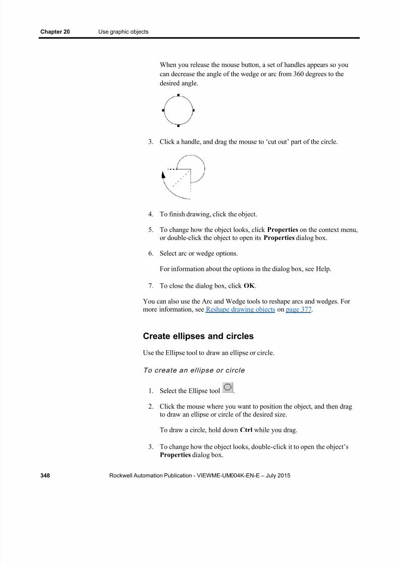
8/15/2019 Factory Talk View ME
http://slidepdf.com/reader/full/factory-talk-view-me 348/635
Chapter 20 Use graphic objects
348 Rockwell Automation Publication - VIEWME-UM004K-EN-E – July 2015
When you release the mouse button, a set of handles appears so youcan decrease the angle of the wedge or arc from 360 degrees to thedesired angle.
3. Click a handle, and drag the mouse to ‘cut out’ part of the circle.
4. To finish drawing, click the object.
5. To change how the object looks, click Properties on the context menu,or double-click the object to open its Properties dialog box.
6. Select arc or wedge options.
For information about the options in the dialog box, see Help.
7. To close the dialog box, click OK .
You can also use the Arc and Wedge tools to reshape arcs and wedges. Formore information, see Reshape drawing objects on page 377 .
Create ellipses and circles
Use the Ellipse tool to draw an ellipse or circle.
To create an el l ipse or circle
1. Select the Ellipse tool .
2. Click the mouse where you want to position the object, and then dragto draw an ellipse or circle of the desired size.
To draw a circle, hold down Ctrl while you drag.
3. To change how the object looks, double- click it to open the object’sProperties dialog box.

8/15/2019 Factory Talk View ME
http://slidepdf.com/reader/full/factory-talk-view-me 349/635
Use graphic objects Chapter 20
Rockwell Automation Publication - VIEWME-UM004K-EN-E – July 2015 349
4. Select circle or ellipse options.
For information about the options in the dialog box, see Help.
5. To close the dialog box, click OK .
Create freehand shapes
Using the Freehand tool is similar to drawing with a pen on paper.
To create a freehand sh ape
1. Select the Freehand tool .
2. Click and drag to create the shape you want.
3. To change how the object looks, double-click it to open the FreehandProperties dialog box.
4. Select freehand options.
For information about the options in the dialog box, see Help.
5. To close the dialog box, click OK .
Create lines
To create a l ine
1. Select the Line tool .
2. Click where you want the line to start, and then drag from the beginning point to the end point.
To draw horizontal or vertical lines, hold down Ctrl while you drag themouse.
3. To change how the line looks, right-click the line and then clickProperties on the context menu. The Line Properties dialog boxopens.
4. Select line options.
For information about the options in the dialog box, see Help.
5. To close the dialog box, click OK .
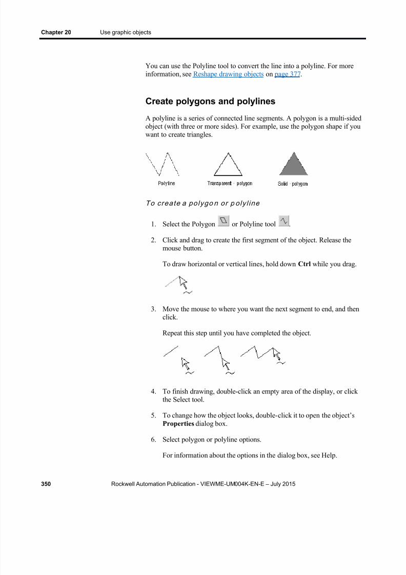
8/15/2019 Factory Talk View ME
http://slidepdf.com/reader/full/factory-talk-view-me 350/635
Chapter 20 Use graphic objects
350 Rockwell Automation Publication - VIEWME-UM004K-EN-E – July 2015
You can use the Polyline tool to convert the line into a polyline. For moreinformation, see Reshape drawing objects on page 377 .
Create polygons and polylines
A polyline is a series of connected line segments. A polygon is a multi-sidedobject (with three or more sides). For example, use the polygon shape if youwant to create triangles.
To crea te a polygo n or p oly l ine
1. Select the Polygon or Polyline tool .
2. Click and drag to create the first segment of the object. Release themouse button.
To draw horizontal or vertical lines, hold down Ctrl while you drag.
3. Move the mouse to where you want the next segment to end, and thenclick.
Repeat this step until you have completed the object.
4. To finish drawing, double-click an empty area of the display, or clickthe Select tool.
5. To change how the object looks, double- click it to open the object’sProperties dialog box.
6. Select polygon or polyline options.
For information about the options in the dialog box, see Help.
8/15/2019 Factory Talk View ME
http://slidepdf.com/reader/full/factory-talk-view-me 351/635
Use graphic objects Chapter 20
Rockwell Automation Publication - VIEWME-UM004K-EN-E – July 2015 351
7. To close the dialog box, click OK .
You can use the Polygon tool to reshape lines, polygons, polylines, andrectangles. For more information, see Reshape drawing objects on page 377 .
Create rectangles and squares
To create a rectangle or s qu are
1. Select the Rectangle tool .
2. Click the mouse where you want to position the object, and then draguntil the rectangle or square is the size you want.
To draw a square, hold down Ctrl while you drag.
3. To change how the object looks, double- click it to open the object’sProperties dialog box.
4. Select rectangle or square options.
For information about the options in the dialog box, see Help.
5. To close the dialog box, click OK .
You can use the Polygon tool to reshape the rectangle into a polygon. For
more information, see Reshape drawing objects on page 377 .
Create rounded rectangles and squares
Due to a Windows limitation, you cannot rotate rounded rectangles androunded squares.
To crea te a rounded rec tangle or s quare
1. Select the Rounded Rectangle tool .
2. Click the mouse where you want to position the object, and then draguntil the rectangle or square is the size you want.
To draw a square, hold down Ctrl while you drag.

8/15/2019 Factory Talk View ME
http://slidepdf.com/reader/full/factory-talk-view-me 352/635
Chapter 20 Use graphic objects
352 Rockwell Automation Publication - VIEWME-UM004K-EN-E – July 2015
3. You can change how rounded the corners are by using the handle thatappears inside the rounded rectangle. Click the handle and drag inwardto increase roundedness, or outward to decrease roundedness.
4. To finish drawing, click the object.
5. To change how the object looks, click Properties on the context menu,or double-click the object to open its Properties dialog box.
6. Select rounded rectangle or square options.
For information about the options in the dialog box, see Help.
7. To close the dialog box, click OK .
For information about using the Rounded Rectangle tool to reshape therounded rectangle, see To reshape rounded rectangles on page 378 .
Use .wmf and .dxf files
Windows metafiles (.wmf) and AutoCAD (.dxf) files are converted todrawing objects (such as lines, ellipses, and polygons) when you importthem. You can edit the drawing objects the same way you edit drawingobjects that you create in FactoryTalk View.
Depending on the complexity of the metafile or AutoCAD file, the convertedimage could consist of 500 or more drawing objects. This would lead to longdisplay load times. In this case, it would be better to covert the .wmf or .dxffile to a bitmap, and then show the bitmap in an image object.
To p lace a .wm f or .dxf f i le in a d isp lay
1. From the Objects menu, select Import .
2. Click the mouse where you want to position the file, and then drag todraw a rectangle.
3. In the Files of type box, select the type of file to import.
4. Navigate to the directory where the file is stored, and then click the fileto import.
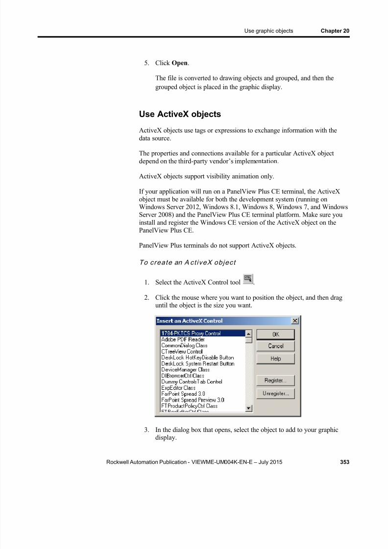
8/15/2019 Factory Talk View ME
http://slidepdf.com/reader/full/factory-talk-view-me 353/635
Use graphic objects Chapter 20
Rockwell Automation Publication - VIEWME-UM004K-EN-E – July 2015 353
5. Click Open .
The file is converted to drawing objects and grouped, and then thegrouped object is placed in the graphic display.
Use ActiveX objects
ActiveX objects use tags or expressions to exchange information with thedata source.
The properties and connections available for a particular ActiveX objectdepend on the third- party vendor’s implementation.
ActiveX objects support visibility animation only.
If your application will run on a PanelView Plus CE terminal, the ActiveXobject must be available for both the development system (running onWindows Server 2012, Windows 8.1, Windows 8, Windows 7, and WindowsServer 2008) and the PanelView Plus CE terminal platform. Make sure youinstall and register the Windows CE version of the ActiveX object on thePanelView Plus CE.
PanelView Plus terminals do not support ActiveX objects.
To crea te an A ct iveX objec t
1. Select the ActiveX Control tool .
2. Click the mouse where you want to position the object, and then draguntil the object is the size you want.
3. In the dialog box that opens, select the object to add to your graphicdisplay.

8/15/2019 Factory Talk View ME
http://slidepdf.com/reader/full/factory-talk-view-me 354/635
Chapter 20 Use graphic objects
354 Rockwell Automation Publication - VIEWME-UM004K-EN-E – July 2015
For information about the options in the dialog box, see Help.
4. Click OK .
The object is placed in the display. Depending on how the third partyimplemented the object, it might be a different size than the rectangleyou drew.
5. To specify the object’s properties and assign tags or expressions to itsconnections, do one of the following:
Right-click the object, and then select Properties to open theobject’s Properties dialog box.
Depending on how the third party implemented the object, it mightnot have a Properties dialog box. If the Properties menu item is
not available, use the next method.
Right-click the object, and then click Property Panel .
6. In the Properties dialog box or Properties tab of the Property Panel ,specify the object’s properties.
7. If desired, set up the properties in the Common tab, as described onSet up objects’ spatial properties, names, and visibility on page 389 .
8. In the Connections tab, assign tags or expressions to the object’sconnections.
9. To close the Properties dialog box, click OK . To close the PropertyPanel , click the Close button.
For information about using the Properties dialog box, see Use theProperties dialog box on page 358 .
For information about using the Property Panel , see Use the Property Panel on page 360 .
This section describes features of the Graphics editor that help you workwith the objects you create. It describes how to:
Select and deselect objects.
Use the Object Explorer to view and select objects.
Use an object’s Properties dialog box to set up th e object’s propertiesand assign tags and expressions to its connections.
Use the Property Panel to set up individual and group object properties, and to assign tags and expressions to individual objects’connections.
Color objects.
Tools and tips forworking withobjects

8/15/2019 Factory Talk View ME
http://slidepdf.com/reader/full/factory-talk-view-me 355/635
Use graphic objects Chapter 20
Rockwell Automation Publication - VIEWME-UM004K-EN-E – July 2015 355
Name objects.
Test how objects look in different states.
Select and deselect objects
To work with an object, you must first select it. You can use the Select toolor the Object Explorer to select objects.
For information about using the Object Explorer, see Use the ObjectExplorer on page 356 .
To select the Select too l
From the Objects menu, select Select , or on the Objects toolbar click
the Select tool .
The mouse pointer changes to a single arrow.
Selec t o bjec ts
To select Do this
An object or group ofobjects
Click the object or group.In the Object Explorer, click the object or group.
An object within a groupof objects
Double-click the group, and then click the object.In the Object Explorer, open the group, and then clickthe object.
Several objects Click the first object, and then Ctrl-click additionalobjects.
All objects in an area Click and drag diagonally to draw a selection borderaround the objects.Ctrl-click objects outside the border to add them to theselection.
All objects in the drawingarea or in a group you areediting
On the Edit menu, click Select All, or press Ctrl+A.
Deselect ob jects
To deselect Do this
An object Ctrl-click the object.
Several objects Press and hold Ctrl, and then drag a selection borderaround the objects.
All selected objects Click in the Drawing area, away from any objects.

8/15/2019 Factory Talk View ME
http://slidepdf.com/reader/full/factory-talk-view-me 356/635
Chapter 20 Use graphic objects
356 Rockwell Automation Publication - VIEWME-UM004K-EN-E – July 2015
Use the Object Explorer
Use the Object Explorer to view and select objects from a tree-list of all theobjects in a display. Groups are listed as expandable items in the tree, with a+ icon.
Use the Object Explorer to select an object that is hidden behind otherobjects in the display, without bringing the object to the front. Objects arelisted in front-to-back order. The object you created most recently is at thefront, unless you move it back using the Send to Back option. For moreinformation about layering objects, see Layer objects on page 381 .
You can also use the Object Explorer to highlight objects by object type,highlight objects that have animation attached, and to highlight objects withspecific tag or expression assignments. For more information, see Highlightobjects in the Object Explorer on page 357 .
The Object Explorer does not show wallpaper objects, nor objects withinActiveX composite objects.
To open the Objec t Explorer, use one of these method s
On the Graphics toolbar, click the Object Explorer tool .
From the View menu, select Object Explorer .

8/15/2019 Factory Talk View ME
http://slidepdf.com/reader/full/factory-talk-view-me 357/635
Use graphic objects Chapter 20
Rockwell Automation Publication - VIEWME-UM004K-EN-E – July 2015 357
Right-click an object, and then click Object Explorer .
You can keep the Object Explorer open as you work in the Graphics editor.For more information about using the Object Explorer, see Help.
Highlight objects in the Object ExplorerYou can use the Object Explorer to highlight:
Specific types of objects
Objects that have animation attached
Objects that have a specific tag or expression assigned to them
The objects are highlighted in red in the Object Explorer and in the graphicdisplay. If your graphic display uses a red background, the highlighting is notvisible in the graphic display.

8/15/2019 Factory Talk View ME
http://slidepdf.com/reader/full/factory-talk-view-me 358/635
Chapter 20 Use graphic objects
358 Rockwell Automation Publication - VIEWME-UM004K-EN-E – July 2015
To highl ight o bjec ts in the Objec t Explorer
In the Object Explorer, click Highlighting on , and then click Settings .
For details about the options in the Highlight Settings dialog box, see Help.
Use the Properties dialog box
Every graphic object has a Properties dialog box that you can use to set upthe object. Depending on how the vendor implemented the object, third-partyActiveX objects might have a Properties dialog box as well.
The Properties dialog box contains tabs that you can use to set up theobject’s p roperties and connections:
In this tab Do this
General Set up the object’s appearance, audio indicator, and touch margins(for buttons), and settings that are unique to the object, such as thebutton action for a push button, whether to use key navigation toselect the object, or whether to link a button to a specific object.For information about touch margins, see Use touch margins onpage 392 . For information about key navigation, see Remove objects from andadding objects to the tab sequence on page 396 . For information about linking buttons to objects, see Link buttons toobjects on page 397 .
States Set up the states for the object, including the value for each stateand whether to show a caption or image for the state.For information about checking that the states are set up the wayyou intended, see Test how objects look in different states on page365 .

8/15/2019 Factory Talk View ME
http://slidepdf.com/reader/full/factory-talk-view-me 359/635
Use graphic objects Chapter 20
Rockwell Automation Publication - VIEWME-UM004K-EN-E – July 2015 359
In this tab Do this
Label For objects that don’t have multiple states, specify whether to use acaption or image on the object.For information about using the Image Browser to select an imageto use in the label, see Use the Image Browser to import images onpage 322 .
Timing Set up the object’s auto repeat (see Repeat a button’s action byholding down the button on page 399 ), or Enter key handshaking (see Ensure values are read by the data source before sending newvalues on page 400 ) settings.
Common Set up the object’s spatial properties, name and visibility. Fordetails, see Set up objects’ spatial properties, names, an d visibility on page 389 .
Connections Assign tags and expressions to the object’s connections. For information, see Assign tags and expressions to graphic objects on page 366 .
The tabs that are available depend on the object:
Some objects have only General and Common tabs.
If an object can have more than one state, the object’s Properties dialog box contains a States tab.
Some objects have unique tabs that are not listed in the table above.
The tabs that an ActiveX object has depends on the vendor’ simplementation, though if you can assign tags or expressions to theobject it has a Connections tab.
T o open an object’s Properties dialog box, use one of thesemethods
Note: To automatically open the object's property dialog box whenyou place the object on a display, use the Settings tab ( Tools > Options >Settings ).
Double-click the object.
Right-click the object, and then click Properties .
Select the object, and then from the Edit menu, click Properties .
In the Property Panel , with the object selected, click the (Custom) property and then click the Browse button .
In the Property Panel , with the object selected, double-click the(Custom) property.

8/15/2019 Factory Talk View ME
http://slidepdf.com/reader/full/factory-talk-view-me 360/635
Chapter 20 Use graphic objects
360 Rockwell Automation Publication - VIEWME-UM004K-EN-E – July 2015
In the Object Explorer, double-click the object.
You can also use the Property Panel to set up an object’s properties, asdescribed next.
For details about setting up a particular object, see Help.
Use the Property Panel
Use the Property Panel to modify the properties of graphic objects andassign tags and expressions to the objects.
The Property Panel is especially useful for making changes to the propertiesof multiple objects at the same time.
To open th e Proper ty Panel , use on e of these methods
On the Graphics toolbar, click the Property Panel tool .
From the View menu, click Property Panel.
Right-click an object, and then select Property Panel.
Right-click an empty area of the display, and then click PropertyPanel.

8/15/2019 Factory Talk View ME
http://slidepdf.com/reader/full/factory-talk-view-me 361/635
Use graphic objects Chapter 20
Rockwell Automation Publication - VIEWME-UM004K-EN-E – July 2015 361
Set up properties
Use the Properties tab of Property Panel to set up the properties of theselected object or objects.
You can keep the Property Panel open as you work in the Graphics editor.You can drag the panel’s borders to make the Property Panel larger orsmaller.
For more information about using the Property Panel to set up an object’s properties, see Help.
Assign tags and expressions to an object’sconnections
Use the Connections tab of Property Panel to assign tags or expressions tothe selected object’s connections. If multiple objects are selected the tab is
blank, because you can assign tags or expressions to only one object at a
time.
How values are updated
The arrows indicate the direction in which the data flows between theconnection and the data source:
A right arrow indicates that the connection sends values to the datasource. The connection is a write connection.

8/15/2019 Factory Talk View ME
http://slidepdf.com/reader/full/factory-talk-view-me 362/635
Chapter 20 Use graphic objects
362 Rockwell Automation Publication - VIEWME-UM004K-EN-E – July 2015
A left arrow indicates that the data source sends values to theconnection. The connection is a read connection.
A double arrow indicates that the data flows in both directions. The
connection is a read-write connection.
For more information about using the Property Panel to assign tags andexpres sions to an object’s connections, see Help.
For more information about assigning tags and expressions to objects, seeAssign tags and expressions to graphic objects on page 366 .
Color objects using the color toolbars
The Foreground Color and Background Color toolbars contain a selection ofcolors you can assign to objects’ color properties.
Abou t co lo r p rop e r ti es
The number of color properties an object has depends on the type of objectand how you set it up. For example, a button with states can use up to sevendifferent colors for each state. When you select colors using the colortoolbars, some properties are assigned the foreground color and some areassigned the background color. Other color properties, such as Fill color,cannot be assigned using the color toolbars (instead, use the object’sProperties dialog box or the Property Panel ).
This table lists the color properties you can assign using the color toolbars:

8/15/2019 Factory Talk View ME
http://slidepdf.com/reader/full/factory-talk-view-me 363/635
Use graphic objects Chapter 20
Rockwell Automation Publication - VIEWME-UM004K-EN-E – July 2015 363
Property Foreground color Background color
Back colorNo Yes
Background color No Yes
Border color Yes No
Caption color Yes No
Caption back color No Yes
Fore color Yes No
Foreground color Yes No
Image color Yes No
Image back color No Yes
Legend color Yes No
Needle color Yes No
Pattern color Yes No
For objects with states, the selected color is applied to the current state’ scolor properties only. In the Property Panel , properties that apply to stateshave St_ at the beginning of the property name.
When to se lec t colors us ing the toolbars
For all the drawing objects except image and panel, you can select colorsfrom the color toolbars before you draw an object (either before or after youclick the object’s tool).
The other objects are always drawn using their default colors, but you canselect the objects and then click the toolbars to change their colors. Thetoolbars are especially useful for quickly assigning the same colors tomultiple objects.
To show a color toolbar
From the View menu, select Toolbars , and then click ForegroundColors or Background Colors .
To c lose a color toolbar
From the View menu, select Toolbars , and then click ForegroundColors or Background Colors , or click the toolbar’s Close button.
Other method s for ass igning c olors
You can also assign colors using an object’s Properties dialog box or theProperty Panel . Use one of these methods if you want to assign separatecolors to different foreground or background color properties, or to choosecolors that don’t appear i n the toolbars.

8/15/2019 Factory Talk View ME
http://slidepdf.com/reader/full/factory-talk-view-me 364/635
Chapter 20 Use graphic objects
364 Rockwell Automation Publication - VIEWME-UM004K-EN-E – July 2015
For example, if you want to use a dark blue background color for a button,with a light blue background color for its image label, you must assign thecolors separately. Using the toolbar would assign the same color to both
properties.
Also use the Properties dialog box or Property Panel to change the defaultcolors for properties that cannot be assigned using the color toolbars.
Name objects
Objects (and groups of objects) are automatically given a name and numberwhen you create them, for example NumericInputEnable4. If desired, youcan assign a more meaningful name to the object, for exampleConveyor_speed_input. Each object in a display must have a unique name.
The object name appears in the status bar, Diagnostics List , Property Panel ,and Object Explorer in FactoryTalk View Studio, and in diagnostics logmessages at run time.
To name an ob jec t in the Proper ty Panel
1. Select the object.
2. In the Property Panel , click the Properties tab.
3. Double-click the (Name) row, and then type the name.
The name must start with a letter, and cannot contain spaces. You canuse the underscore character (_).
To name an objec t in i t s Proper t ies d ia log bo x
1. Double-click the object to open its Properties dialog box.
2. Click the Common tab.
3. In the Name box, type the name.
The name must start with a letter, and cannot contain spaces. You canuse the underscore character (_).
To name a group ob jec t
1. Select the group object.
2. In the Property Panel , click the Properties tab.
3. Double-click the (GroupName) row, and then type the name.

8/15/2019 Factory Talk View ME
http://slidepdf.com/reader/full/factory-talk-view-me 365/635
Use graphic objects Chapter 20
Rockwell Automation Publication - VIEWME-UM004K-EN-E – July 2015 365
The name must start with a letter, and cannot contain spaces. You canuse the underscore character (_).
Test how objects look in different states
To make sure the different states for an object are set up correctly, you canview them using the States toolbar or the Property Panel .
To open th e States toolbar
From the View menu, select Toolbars , and then click States .
To view an object’s sta tes us ing the Sta tes toolbar
1. Select one or more objects.
2. In the States toolbar, select the state to view.
If you selected multiple objects, the toolbar shows the states that arecommon to all the objects.
3. To view the next state, select it in the toolbar or press the DownArrow key on your keyboard.
You can also use these keys to select the next state to view:
To view the previous state, press the Up Arrow key.
To view the first state, press the Home key.
To see the last state, press the End key.
To view an object’s states using the Property Panel
1. Select one or more objects.
2. In the Property Panel , click the State property and then select thestate to view.
3. To view the next state quickly, double-click the row, or press the Enterkey on your keyboard.

8/15/2019 Factory Talk View ME
http://slidepdf.com/reader/full/factory-talk-view-me 366/635
Chapter 20 Use graphic objects
366 Rockwell Automation Publication - VIEWME-UM004K-EN-E – July 2015
You can assign tags and expressions to many graphic objects, includingActiveX objects (depending, of course, on how the vendor implemented theobject). This section describes how to:
Assign tags to graphic objects. Use expressions to manipulate tag values.
Replace tags using tag substitution.
Use tag placeholders so the same display can be used with differentsets of tags.
Assign tags
To assign tags to a graphic object, use one of these methods:
Double- click the object to open the object’s Properties dialog box, andthen assign tags in the Connections tab.
Select the object and then assign tags in the Connections tab of the
Property Panel .
Assign tags andexpressions tographic objects

8/15/2019 Factory Talk View ME
http://slidepdf.com/reader/full/factory-talk-view-me 367/635
Use graphic objects Chapter 20
Rockwell Automation Publication - VIEWME-UM004K-EN-E – July 2015 367
Select the object, and then from the Edit menu, select Connections .Assign tags in the Connections tab of the Properties dialog box.
Right-click the object, and then select Connections . Assign tags in the
Connections tab of the Properties dialog box.For information about:
Use the Tag Browser , see Use the Tag Browser on page 90 .
Use the Properties dialog box, see Use the Properties dialog box on page 358 .
Use the Property Panel , see Use the Property Panel on page 360 .
Use expressions to manipulate tag values
Many of the connections to which you can assign a tag also permit the use ofexpressions to perform logical or mathematical calculations on tag values. Ifyou assign an expression, FactoryTalk View monitors the expression valuerather than the original tag value. For example, your machine might sendvalues to the data source in the form of temperature in degrees Celsius. Youcould use an expression to convert the value to degrees Fahrenheit, and thenmonitor the expression result rather than the original tag value.
If you can assign an expression, a Browse button is present in the Exprncolumn in the Connections tab.
To speci fy an express ion , do on e of the fo l lowin g
In the Tag / Expression column, type the expression.
In the Exprn column, click the Browse button and then create anexpression in the Expression editor. Use this method if you want tocheck the expression syntax, or to use multiple lines for the expression.
For more information about expressions, see Use expressions on page 475 .

8/15/2019 Factory Talk View ME
http://slidepdf.com/reader/full/factory-talk-view-me 368/635
Chapter 20 Use graphic objects
368 Rockwell Automation Publication - VIEWME-UM004K-EN-E – July 2015
Replace tags using tag substitution
You can replace tags assigned to the graphic objects in your display by usingtag substitution. You can also replace the tags used in expressions assigned tographic objects.
For example, if you assign a tag called HoistHeight to multiple objects in thedisplay, and then decide to use the tag Hoist_height instead, you can use tagsubstitution to quickly replace the old tag with the new tag.
You can replace:
A tag name (with or without folder names)
A folder name
The text in an expression
Tags contained in embedded variables
To replace tags
1. Select one or more objects.
To select all the objects in the display, from the Edit menu, selectSelect All .
2. From the Edit menu, select Tag Substitution .
3. To replace the tags for a single object, you can right-click it and thenselect Tag Substitution .
For details about the options in the Tag Substitution dialog box, see Help.
A log file is shown after substitution. It provides details on the substitution process and results. If the substitution fails, the reason will be shown. Thelast line shows where the log file is located in case you want to review it inthe future.
8/15/2019 Factory Talk View ME
http://slidepdf.com/reader/full/factory-talk-view-me 369/635
Use graphic objects Chapter 20
Rockwell Automation Publication - VIEWME-UM004K-EN-E – July 2015 369
Replace tags using Find and Replace
You can replace tags or components that refer to tags using Find andReplace, a function that has been added with version 7.00.00.
To replace tags
1. From the tool bar, click , or select Replace from the Tools menu, or press CTRL+H.
2. Click the browse button ( ) next to Find what, which launches theTag Browser .
Navigate to the correct folder in the left pane, and then select thetag in the right pane.
Click OK to save the selection and close the browser.
3. Click the browse button next to Replace with. Select the replacementtag from the Tag Browser and click OK to save the selection and closethe browser.
4. Click on the browse button next to Find within and clear all the check boxes except Graphic Objects. Click OK to save the selection andclose the dialog box.
5. Identify the word search limitations in Find Options .
6. Select the Direction , in which to search:
Select Up to search for the tag or text string in all components before the shown one.
Select Down to search for the tag or text string in all componentsafter the shown one.
7. To replace items, select Confirm replacement if needed, then:
To select individual items to replace, click Find Next and thenclick Replace , when the correct item is shown or
To replace all tags, Click Replace All to replace all found items.
If needed, click the View Log File button to show a text file of the results ofthe Replace, Replace All or Undo Replace functions.
To undo replacements, click Undo Replace . Only the last replace or replaceall action can be undone. Undo will not be successful if a component has
been manually edited after the replace action.
8/15/2019 Factory Talk View ME
http://slidepdf.com/reader/full/factory-talk-view-me 370/635
Chapter 20 Use graphic objects
370 Rockwell Automation Publication - VIEWME-UM004K-EN-E – July 2015
Use tag placeholders
Tag placeholders provide a way to use one graphic display to represent anumber of similar operations.
For example, suppose you are creating displays for a plant that cans corn and peas. The machinery used in both processes is identical. Instead of creatingtwo displays and specifying corn-related tags in one display and pea-relatedtags in another, you can create one display and not specify any tag names.Where a tag name is required, type a tag placeholder.
You can use tag placeholders wherever you would normally assign a tag toan object, including in expressions and embedded variables. You can also usetag placeholders in the expressions you create to animate objects.
You can also use tag placeholders with global objects.
You can use tag placeholders in:
The graphic display that opens when the application is first run.
Graphic displays that are opened using a Goto display button.
Graphic displays that are opened using a display list selector.
The graphic display that opens when the logout button is pressed to logthe logged-on user out.
The graphic display specified in the Project Settings Runtime tabwhen auto logout is enabled.
Graphic displays that are opened using the Remote Display Number global connection.
Use parameter files or parameter lists to specify which tags or folders tosubstitute for which placeholders. For global objects, you can specify the tagsor folders of tags using global object parameters.
For more information about using parameter files, parameter lists, and globalobject parameters, see Use parameters and global objects on page 501 .
Create tag placeho lders
A tag placeholder is the cross-hatch character (#) followed by a number from1 to 500.
The tag placeholder can replace any part of a tag name, including foldernames. For example, you could create a parameter file specifying that the tag
placeholder #1=Folder1. You could assign the folder and a tag name to agraphic object’s connection: #1\Tag1 .
You can assign tag placeholders in:

8/15/2019 Factory Talk View ME
http://slidepdf.com/reader/full/factory-talk-view-me 371/635
Use graphic objects Chapter 20
Rockwell Automation Publication - VIEWME-UM004K-EN-E – July 2015 371
The Connections tab of an object’s Properties dialog box.
The Connections tab of the Property Panel .
The Expression box in the Animation dialog box.
Anywhere that you can insert an embedded variable. For informationabout embedded variables, see Use embedded variables on page 493 .
To create a tag placeho lder
Type the cross-hatch character followed by a number (no space in between). For example, #1.
Once you have drawn an object, you can select the object and work with it.You can:
Move objects Copy objects
Duplicate objects
Resize objects
Reshape drawing objects
Delete objects
Move objects
You can move objects using the mouse or the keyboard. The keys give youfine positioning, allowing you to move objects in small increments. You canalso use the grid to position objects precisely.
Another option is to position an object using the object’s Top and Left properties in the Property Panel . For information about using the PropertyPanel , see Use the Property Panel on page 360 .
You can also specify an object’s position using the Common tab in theobject’s Properties dialog box. For more information, see Set up objects’spatial properties, names, and visibility on page 389 .
Once you have moved objects into position, you might want to align otherobjects with them, or lock them into place.
For information about aligning objects, see Align objects on page 382 .
For information about locking objects into position, see Lock objects into position on page 387 .
Perform basicoperations on
objects
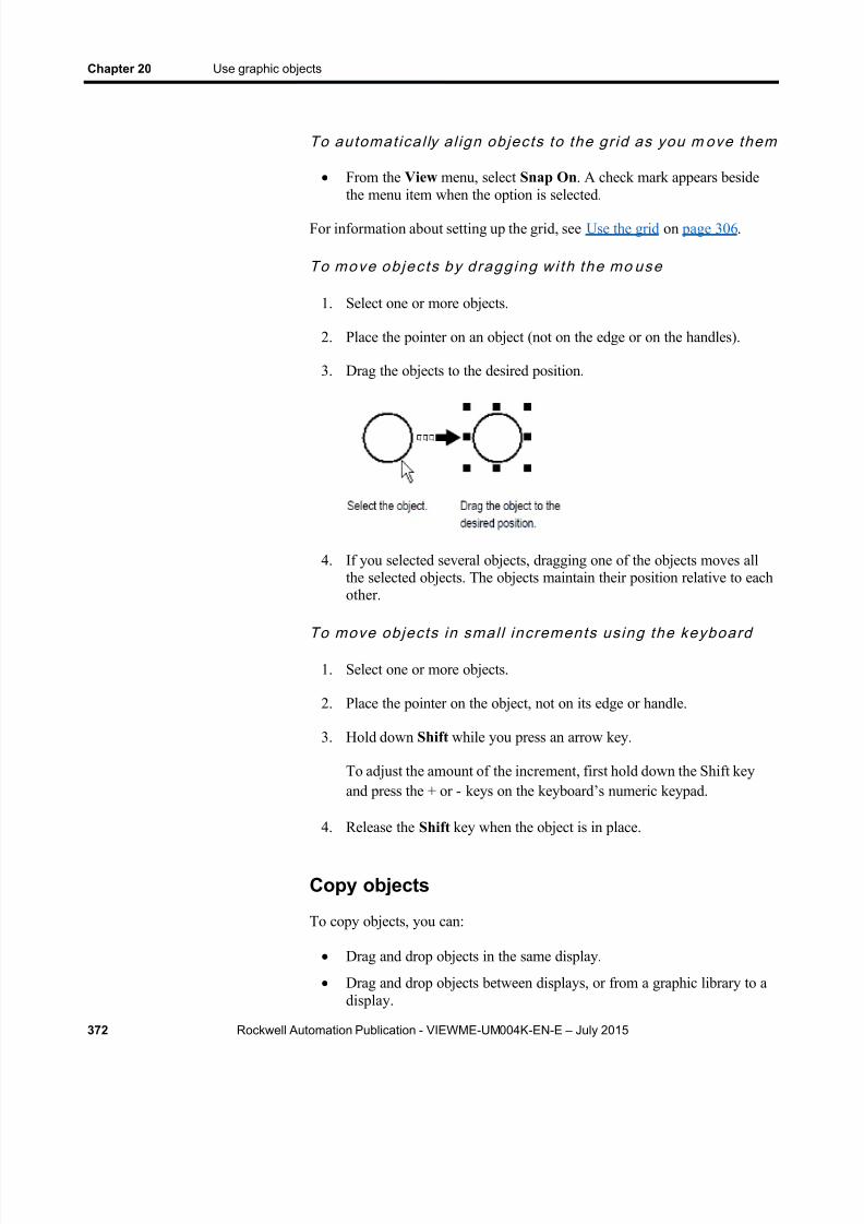
8/15/2019 Factory Talk View ME
http://slidepdf.com/reader/full/factory-talk-view-me 372/635
Chapter 20 Use graphic objects
372 Rockwell Automation Publication - VIEWME-UM004K-EN-E – July 2015
To automat ica l ly a l ign objec ts to the gr id as you m ove them
From the View menu, select Snap On . A check mark appears besidethe menu item when the option is selected.
For information about setting up the grid, see Use the grid on page 306 .
To move ob jec t s by d ragg ing wi th the mo use
1. Select one or more objects.
2. Place the pointer on an object (not on the edge or on the handles).
3. Drag the objects to the desired position.
4. If you selected several objects, dragging one of the objects moves allthe selected objects. The objects maintain their position relative to eachother.
To move objec ts in smal l increments us ing the keyboard
1. Select one or more objects.
2. Place the pointer on the object, not on its edge or handle.
3. Hold down Shift while you press an arrow key.
To adjust the amount of the increment, first hold down the Shift keyand press the + or - keys on the keyboard’s numeric keypad.
4. Release the Shift key when the object is in place.
Copy objects
To copy objects, you can:
Drag and drop objects in the same display.
Drag and drop objects between displays, or from a graphic library to adisplay.

8/15/2019 Factory Talk View ME
http://slidepdf.com/reader/full/factory-talk-view-me 373/635
Use graphic objects Chapter 20
Rockwell Automation Publication - VIEWME-UM004K-EN-E – July 2015 373
Copy and paste objects.
When an object is copied, any animation attached to the object is also copied.If a group is copied, the new copy of the group can be ungrouped to
individual objects, just like the original.
Copy objec ts wi th m ul t ip le languages
If an object has multiple language strings set up, copying the object copies allthe languages. You have two options for pasting an object with multiplelanguage strings into an application:
If you use the Paste command, the object is pasted into an applicationwith different languages, only the strings for languages that are used bythe application are pasted. If the new application has languages that arenot set up for the object, those language strings are undefined and will
be shown with single question marks.
If you use the Paste without localized strings command, the object is pasted with only the current localized language. The Paste withoutlocalized strings command removes all other language strings fromthe object and sets the language strings to Undefined.
For more information about setting up multiple languages, see Set uplanguage switching on page 197 .
To copy o bjec ts in the same display
1. Select one or more objects.
2. Drag the object, and then press Ctrl .
When you press Ctrl , a plus sign is added to the cursor.
3. When the object is where you want it, release the mouse button andthen the Ctrl key.
A new copy of the object is created.
If you selected several objects, dragging one of the objects copies all
the selected objects. The objects maintain their position relative to eachother.
To drag objec ts be tween displays
1. Open both displays (or a graphic library and a display).
2. Position or resize the displays so both are visible.
For more information, see Resize displays on page 311 .

8/15/2019 Factory Talk View ME
http://slidepdf.com/reader/full/factory-talk-view-me 374/635
Chapter 20 Use graphic objects
374 Rockwell Automation Publication - VIEWME-UM004K-EN-E – July 2015
3. Select one or more objects.
4. Click the selected object and drag it to the new display.
If you selected several objects, dragging one of the objects copies allthe selected objects. The objects maintain their position relative to eachother.
Copy and pas te objec ts
You can cut, copy, or paste objects using the menu items on the Edit menu orthe buttons on the toolbar.
Once you cut or copy an object, you can paste it anywhere in the drawingarea of:
The same graphic display.
A graphic display in the same or a different application.
A graphic library in the same or a different application.
To cu t o r cop y ob jec t s
1. Select one or more objects.
2. From the Edit menu, select Cut or Copy , or click the Cut tool , or
the Copy tool on the Graphics toolbar.
To remove the original object, click Cut .
To retain the original object, click Copy .
To pas te objec ts
1. Click in the display or library to paste to.
2. From the Edit menu, select Paste , or click the Paste tool on theGraphics toolbar.
Duplicate objects
When an object is duplicated, any animation attached to the object is alsoduplicated. If a group is duplicated, the new copy of the group can beungrouped to individual objects.

8/15/2019 Factory Talk View ME
http://slidepdf.com/reader/full/factory-talk-view-me 375/635
Use graphic objects Chapter 20
Rockwell Automation Publication - VIEWME-UM004K-EN-E – July 2015 375
To dupl ica te objec ts
1. Select one or more objects.
2. From the Edit menu, select Duplicate , or click the Duplicate toolon the Graphics toolbar.
The duplicated object is placed slightly offset from the original.
Duplicate also duplicates actions. For example, if you duplicate an object,move it, and then duplicate it again, the second Duplicate will, in one step,duplicate and move the object. This is useful for creating a series of objectswith an equal distance between them.
Duplicate works until you deselect the object.
Resize objects
You can resize objects using the mouse or using the keyboard. The keys letyou resize objects in small increments. You can also use the grid to resizeobjects precisely.
Another option is to size an object using the object’s Height and Width properties in the Property Panel . This method is especially useful forquickly resizing multiple objects to the same size. For information aboutusing the Property Panel , see Use the Property Panel on page 360 .
You can also specify an object’s size using the Common tab in the object’sProperties dialog box. For more information, see Set up objects’ spatial
properties, names, and visibility on page 389 .
When you resize text objects, if you have selected the Size to fit option, thefont size is adjusted to fit the new object size as closely as possible.
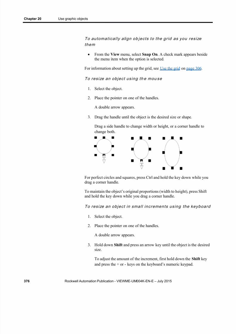
8/15/2019 Factory Talk View ME
http://slidepdf.com/reader/full/factory-talk-view-me 376/635
Chapter 20 Use graphic objects
376 Rockwell Automation Publication - VIEWME-UM004K-EN-E – July 2015
To automat ica l ly a lign ob jec ts to the gr id as you res izethem
From the View menu, select Snap On . A check mark appears besidethe menu item when the option is selected.
For information about setting up the grid, see Use the grid on page 306 .
To res ize an objec t us ing th e mou se
1. Select the object.
2. Place the pointer on one of the handles.
A double arrow appears.
3. Drag the handle until the object is the desired size or shape.
Drag a side handle to change width or height, or a corner handle tochange both.
For perfect circles and squares, press Ctrl and hold the key down while youdrag a corner handle.
To maintain the object’s original proportions (width to h eight), press Shiftand hold the key down while you drag a corner handle.
To res ize an objec t in smal l increments us ing the keyboard
1. Select the object.
2. Place the pointer on one of the handles.
A double arrow appears.
3. Hold down Shift and press an arrow key until the object is the desiredsize.
To adjust the amount of the increment, first hold down the Shift keyand press the + or - keys on the keyboard’s numeric keypad.

8/15/2019 Factory Talk View ME
http://slidepdf.com/reader/full/factory-talk-view-me 377/635
Use graphic objects Chapter 20
Rockwell Automation Publication - VIEWME-UM004K-EN-E – July 2015 377
Reshape drawing objects
You can reshape arcs, lines, polygons, polylines, rectangles, roundedrectangles, and wedges.
To reshape l ines , rec tangles , poly l ines , and polyg ons
1. Select the object you want to reshape.
2. Click the Polygon tool , or right-click the object and then selectEdit .
The cursor changes to the Polygon tool, and handles appear on theobject.
3. Move the cursor over any line or corner of the object.
A handle with a cross-hair appears.
4. Drag the handle until the object is the desired shape.
Dragging from a point along the line (between corners) creates a newangle between the two corners.
5. To delete an angle, position the pointer at the tip of the angle, and then press Delete.
To reshape arcs and wedg es
1. Select the object you want to reshape.
2. Click the Arc tool , or the Wedge tool , or right-click the object
and then select Edit .
The cursor changes to the Arc or Wedge tool, and handles appear onthe object.
3. Place the pointer on one of the handles.
A cross-hair appears.
4. Drag the handle until the object is the desired shape.
8/15/2019 Factory Talk View ME
http://slidepdf.com/reader/full/factory-talk-view-me 378/635
Chapter 20 Use graphic objects
378 Rockwell Automation Publication - VIEWME-UM004K-EN-E – July 2015
To reshape round ed rec tangles
1. Select the rounded rectangle.
2. Click the Rounded Rectangle tool , or right-click the object andthen select Edit .
A handle appears inside the rounded rectangle.
3. Click the handle and drag inward to increase roundedness, or outwardto decrease roundedness.
Delete objects
If you accidentally delete an object, use the Undo tool to restore it.
To delete ob jects
1. Select one or more objects.
2. From the Edit menu, select Delete , or press Delete on the keyboard.
To dele te al l the objec ts in the d isplay
From the Edit menu, select Clear All .
Group and ungroup objects
Grouping combines several objects into a single object so you canmanipulate them as a single object. Grouping is useful for keeping objects inthe same position relative to each other. You can cut, copy, and paste groups,arrange the group as a single object relative to other objects, and apply thesame properties to all the members of the group at once.
You can attach animation to a group, and any animation attached toindividual objects in the group remains active. The group animationgenerally takes precedence over the animation of individual objects withinthe group. For more information, see Apply animation to groups on page471 .
Deleting a group deletes all individual objects in the group.
To g roup ob jec t s
1. Select all the objects you want grouped.
Work with groups ofobjects

8/15/2019 Factory Talk View ME
http://slidepdf.com/reader/full/factory-talk-view-me 379/635
Use graphic objects Chapter 20
Rockwell Automation Publication - VIEWME-UM004K-EN-E – July 2015 379
2. From the Arrange menu, select Group , or on the Graphics toolbar,
click the Group tool .
3. The handles around each object are replaced by a set of handles aroundthe group.
To ungroup ob jec t s
1. Select the group of objects to ungroup.
2. From the Arrange menu, select Ungroup , or on the Graphics toolbar,
click the Ungroup tool .
The handles around the group are replaced with handles around eachobject.
Ungrouping deletes any animation attached to the group, because the groupno longer exists. However, animation attached to the individual objects thatwere in the group remains active.
Edit groups of objects
Edit a group the same way you would edit an individual object. You can:

8/15/2019 Factory Talk View ME
http://slidepdf.com/reader/full/factory-talk-view-me 380/635
Chapter 20 Use graphic objects
380 Rockwell Automation Publication - VIEWME-UM004K-EN-E – July 2015
Use the Property Panel to apply the same properties to all themembers of the group at once. For example, change the line width ofall objects in the group to 2 pixels.
For information about using the Property Panel , see Use the PropertyPanel on page 360 .
Use the toolbars to apply the same pattern style, background style,foreground colors, and background colors to all the members of thegroup.
For objects with states, use the States toolbar to cycle through thestates and apply the same properties to the states for each object in thegroup at once. When you select a group containing objects with states,only the states that are common to all objects in the group appear in thetoolbar.
For more information about using the States toolbar, see To open theStates toolbar on page 365 .
Edit objects within a group
You can also edit individual objects within the group without breaking thegroup, which is particularly useful when you have animation attached to thegroup.
To edi t objec ts wi th in a group
1. Double-click the grouped object, or right-click it and then click Edit . Ahatched border appears around the group.
When the hatched border is around the group, you are in group editmode. In this mode, you can select individual objects in the group andmodify them.
You can also add new objects to the group.
2. To select an individual object (or a group) in the group, click it. Youcan also use the Object Explorer to select objects within the group.
The status bar and Object Explorer indicate which object or group isselected.
3. Make your changes to the object.

8/15/2019 Factory Talk View ME
http://slidepdf.com/reader/full/factory-talk-view-me 381/635
Use graphic objects Chapter 20
Rockwell Automation Publication - VIEWME-UM004K-EN-E – July 2015 381
You can change the selected object’s shape, size, or position, or use theobject’s Properties dialog box or the Property Panel to edit theobject’s properties.
4. If desired, create new objects inside the hatched border.
5. To stop editing, click outside the group.
You can arrange objects (or groups of objects) in a number of ways. Youcan:
Layer objects by moving them in front of or behind other objects.
Align objects with each other and with the grid.
Space objects horizontally or vertically.
Flip drawing objects horizontally or vertically. Rotate drawing objects.
Lock objects into position.
Layer objects
You can layer objects (or groups of objects) on top of each other. Objects arelayered in the order they are created, with the most recently created object ontop. Change the layer order with Send to Back and Bring to Front .
Send to Back moves the selected object to the bottom layer.
Bring to Front moves the selected object to the top layer.
To br ing an objec t to the f ront
1. Select the object.
To select an object that’s behind another object, place your pointer onthe front object, click once, pause, and then click again. Do notdouble-click and do not move the mouse.
You can also select a concealed object easily by clicking the object inthe Object Explorer.
Arrange objects

8/15/2019 Factory Talk View ME
http://slidepdf.com/reader/full/factory-talk-view-me 382/635
Chapter 20 Use graphic objects
382 Rockwell Automation Publication - VIEWME-UM004K-EN-E – July 2015
2. From the Arrange menu, select Bring to Front , or click the Bring to
Front tool .
To send an objec t to the back
1. Select an object.
2. From the Arrange menu, select Send to Back , or click the Send to
Back tool .
Align objects
You can align objects (or groups of objects) with each other and with thegrid.
To a l ign o bjec ts
1. Select the objects you want to align.
2. From the Arrange menu, select the appropriate menu item, or click atool on the Alignment toolbar:
This button or menu item Aligns selected objects with the
Align Left Left-most selected object
Align CenterHorizontal center of all selected objects
Align RightRight-most selected object
Align TopTop-most selected object
Align MiddleVertical center of all selected objects

8/15/2019 Factory Talk View ME
http://slidepdf.com/reader/full/factory-talk-view-me 383/635
Use graphic objects Chapter 20
Rockwell Automation Publication - VIEWME-UM004K-EN-E – July 2015 383
This button or menu item Aligns selected objects with the
Align BottomBottom-most selected object
Align Center PointsCenter of all selected objects
Align to GridGrid
To automat ica l ly a lign ob jec ts to the gr id as you crea te ormove them
From the View menu, select Snap On . A check mark appears besidethe menu item when the option is selected.
For information about setting up the grid, see Use the grid on page 306 .
Examples: Align objects left, right, and center
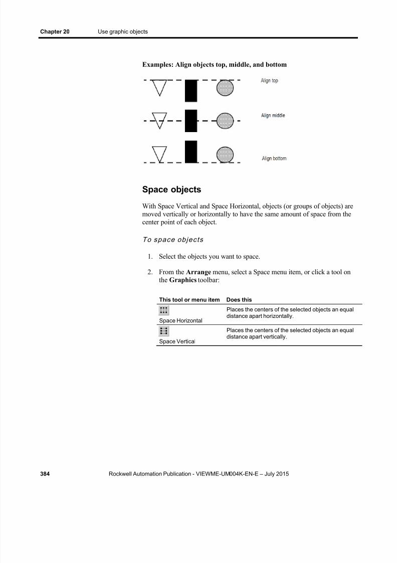
8/15/2019 Factory Talk View ME
http://slidepdf.com/reader/full/factory-talk-view-me 384/635
Chapter 20 Use graphic objects
384 Rockwell Automation Publication - VIEWME-UM004K-EN-E – July 2015
Examples: Align objects top, middle, and bottom
Space objectsWith Space Vertical and Space Horizontal, objects (or groups of objects) aremoved vertically or horizontally to have the same amount of space from thecenter point of each object.
To space objec ts
1. Select the objects you want to space.
2. From the Arrange menu, select a Space menu item, or click a tool onthe Graphics toolbar:
This tool or menu item Does this
Space Horizontal
Places the centers of the selected objects an equaldistance apart horizontally.
Space Vertical
Places the centers of the selected objects an equaldistance apart vertically.

8/15/2019 Factory Talk View ME
http://slidepdf.com/reader/full/factory-talk-view-me 385/635
Use graphic objects Chapter 20
Rockwell Automation Publication - VIEWME-UM004K-EN-E – July 2015 385
Examples: Space objects vertically and horizontally
Flip drawing objects
Flipping an object creates a mirror image of the object. You can flip all thedrawing objects (or groups of drawing objects) except text, images, and
panels.
To f l ip a drawing objec t
1. Click the object.
2. From the Arrange menu, select a Flip menu item, or click a tool on theGraphics toolbar:
This tool or menu item Flips selected objects
Flip VerticalTop to bottom (upside-down)
Flip HorizontalLeft to right
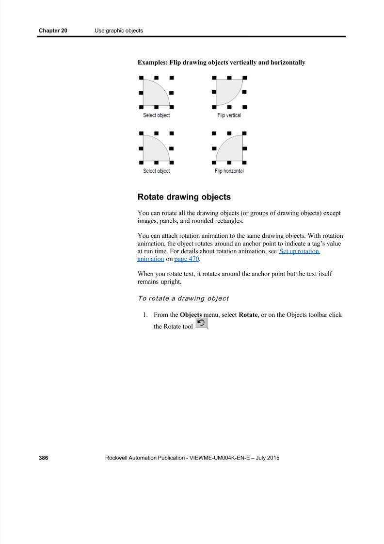
8/15/2019 Factory Talk View ME
http://slidepdf.com/reader/full/factory-talk-view-me 386/635
Chapter 20 Use graphic objects
386 Rockwell Automation Publication - VIEWME-UM004K-EN-E – July 2015
Examples: Flip drawing objects vertically and horizontally
Rotate drawing objects
You can rotate all the drawing objects (or groups of drawing objects) exceptimages, panels, and rounded rectangles.
You can attach rotation animation to the same drawing objects. With rotationanimation, the object rotates around an anchor point to indicate a tag’s valueat run time. For details about rotation animation, see Set up rotationanimation on page 470 .
When you rotate text, it rotates around the anchor point but the text itselfremains upright.
To ro ta te a drawing objec t
1. From the Objects menu, select Rotate , or on the Objects toolbar click
the Rotate tool .

8/15/2019 Factory Talk View ME
http://slidepdf.com/reader/full/factory-talk-view-me 387/635
Use graphic objects Chapter 20
Rockwell Automation Publication - VIEWME-UM004K-EN-E – July 2015 387
2. Click the object you want to rotate. A small crosshair circle appears inthe middle of the object. This is the anchor point that is used as thecenter of rotation.
3. To move the center of rotation, click the cross-hair and drag it to a newanchor position. The anchor can be inside or outside the object.
4. Click an edge of the object and drag in the direction you want to rotateit.
To rotate the object in five-degree increments, press Ctrl while youdrag.
5. When the object is in the desired position, release the mouse button.
Lock objects into position
You can lock graphic objects (or groups of objects) into position byconverting them to wallpaper. Once you convert objects to wallpaper, youcannot select or edit them unless you unlock the wallpaper. Wallpaperobjects cannot be animated at run time.
If the grid is on, wallpaper objects are positioned behind the grid. If you justwant to lock the objects into place while you’re working in the display,unlock the wallpaper when you’re finished. If you want to use the wallpaperobjects as a background for your display, leave the wallpaper locked. Formore information about creating a background for your display, see Create a
background for your display on page 312 .

8/15/2019 Factory Talk View ME
http://slidepdf.com/reader/full/factory-talk-view-me 388/635
8/15/2019 Factory Talk View ME
http://slidepdf.com/reader/full/factory-talk-view-me 389/635
Rockwell Automation Publication - VIEWME-UM004K-EN-E – July 2015 389
Chapter 21
Set up graphic objects
This chapter describes how to set up graphic objects. It describes how to:
Set up objects’ spatial properties, names, and visibility
Work with objects that have states
Position objects for touch screens
Assign function keys to buttons
Use the keyboard to navigate to and select objects at run time
Link buttons to lists and trends
Repeat a button’s action by holding down the button
Ensure values are read by the data source before sending new values
Set up objects
For objects that are not described in other chapters of the manual, thischapter provides information about how to use the objects.
For information about creating graphic objects, see Use graphic objects on page 331 .
For information about creating and setting up the trend graphic object, seeSet up trends on page 535 .
For information about creating and setting up the RecipePlus graphicobjects, see Set up RecipePlus on page 547 .
Every graphic object has a Common tab in its Properties dialog box. Usethe Common tab to set up the following properties for the object:
Height and width
Top and left position
Name
Visibility
For ActiveX and trend objects, you can also set up these properties:
Focus highlight
S et up objects’spatial properties,
names, andvisibility

8/15/2019 Factory Talk View ME
http://slidepdf.com/reader/full/factory-talk-view-me 390/635
Chapter 21 Set up graphic objects
390 Rockwell Automation Publication - VIEWME-UM004K-EN-E – July 2015
Key navigation
For details about the options in the Common tab, see Help.
The graphic objects that have states have a States tab in their Properties dialog box.
Tips for setting upobjects with states

8/15/2019 Factory Talk View ME
http://slidepdf.com/reader/full/factory-talk-view-me 391/635
Set up graphic objects Chapter 21
Rockwell Automation Publication - VIEWME-UM004K-EN-E – July 2015 391
For details about the options in the States tab, see Help.
Copy and paste properties from one state toanother
Often, you want most of the properties to be the same from state to state,with only one or two settings changing to distinguish the different states.
To simplify setting up states when many of the properties are the same, youcan copy and paste settings from one state to another. For details, see Help.
Add and remove states
Some graphic objects have a configurable number of states. For theseobjects, you can use the Insert State and Delete State buttons in the Statestab, to add and remove states without returning to the General tab. TheNumber of States setting on the General tab is automatically updated.
For more information about the Insert State and Delete State buttons, seeHelp.
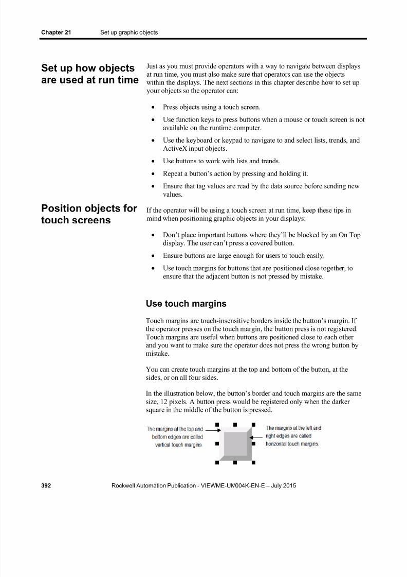
8/15/2019 Factory Talk View ME
http://slidepdf.com/reader/full/factory-talk-view-me 392/635
Chapter 21 Set up graphic objects
392 Rockwell Automation Publication - VIEWME-UM004K-EN-E – July 2015
Just as you must provide operators with a way to navigate between displaysat run time, you must also make sure that operators can use the objectswithin the displays. The next sections in this chapter describe how to set upyour objects so the operator can:
Press objects using a touch screen.
Use function keys to press buttons when a mouse or touch screen is notavailable on the runtime computer.
Use the keyboard or keypad to navigate to and select lists, trends, andActiveX input objects.
Use buttons to work with lists and trends.
Repeat a button’s action by pressing and holding it.
Ensure that tag values are read by the data source before sending new
values.If the operator will be using a touch screen at run time, keep these tips inmind when positioning graphic objects in your displays:
Don’t place important buttons where they’ll be blocked by an On Topdisplay. The user can’t press a covered button.
Ensure buttons are large enough for users to touch easily.
Use touch margins for buttons that are positioned close together, toensure that the adjacent button is not pressed by mistake.
Use touch margins
Touch margins are touch- insensitive borders inside the button’s margin. Ifthe operator presses on the touch margin, the button press is not registered.Touch margins are useful when buttons are positioned close to each otherand you want to make sure the operator does not press the wrong button bymistake.
You can create touch margins at the top and bottom of the button, at thesides, or on all four sides.
In the illustration below, the button’s border and touch margins are the samesize, 12 pixels. A button press would be registered only when the darkersquare in the middle of the button is pressed.
Set up how objectsare used at run time
Position objects fortouch screens

8/15/2019 Factory Talk View ME
http://slidepdf.com/reader/full/factory-talk-view-me 393/635
Set up graphic objects Chapter 21
Rockwell Automation Publication - VIEWME-UM004K-EN-E – July 2015 393
The bound ing b ox
If the object’s shape is a circle or ellipse, the touch margin applies to theobject’s bounding box, not the object’s border. The bounding box is aninvisible square or rectangle that surrounds the object. When you select theobject, the selection handles show the location of the bounding box.
To create touch m argins , use one of these methods
In the General tab of the button’s Properties dialog box, type thenumber of pixels for the touch margins in the Horizontal margin andVertical margin boxes.
In the Properties tab of the Property Panel , type the number of pixelsfor the HorizontalMargin and VerticalMargin properties.
You can assign function keys to the buttons in your displays to allow theoperator to press the buttons using the function keys on the runtime terminal(or the function keys on a keyboard, if one is available). You can also assigna function key to the numeric input cursor point.
You can assign up to 34 function keys to each graphic display.
Here are some tips for assigning function keys:
Where possible, use the same function keys for the same operations inall your graphic displays. For example, if every display contains a Gotodisplay button that returns the operator to a graphic display called MainMenu, assign the same function key to this button in each display.
Include the name of the function key assigned to a button in a captionon the button.
For buttons with multiple states, include the function key name in thecaption for each state, or create a text object to use as a label for the
button (so that you don’t have to set up the caption for each state), andthen group the text and button together.
If your application will run on a PanelView Plus 7, PanelView Plus 6,PanelView Plus, PanelView Plus Compact, or PanelView Plus CEterminal, assign keys that are supported by the runtime terminal.Different sizes of terminals have different function keys.
Assign functionkeys to buttons
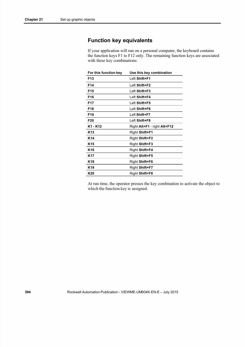
8/15/2019 Factory Talk View ME
http://slidepdf.com/reader/full/factory-talk-view-me 394/635
Chapter 21 Set up graphic objects
394 Rockwell Automation Publication - VIEWME-UM004K-EN-E – July 2015
Function key equivalents
If your application will run on a personal computer, the keyboard containsthe function keys F1 to F12 only. The remaining function keys are associatedwith these key combinations:
For this function key Use this key combination
F13 Left Shift+F1
F14 Left Shift+F2
F15 Left Shift+F3
F16 Left Shift+F4
F17 Left Shift+F5
F18 Left Shift+F6
F19 Left Shift+F7
F20 Left Shift+F8
K1 - K12 Right Alt+F1 - right Alt+F12
K13 Right Shift+F1
K14 Right Shift+F2
K15 Right Shift+F3
K16 Right Shift+F4
K17 Right Shift+F5
K18 Right Shift+F6
K19 Right Shift+F7
K20 Right Shift+F8
At run time, the operator presses the key combination to activate the object towhich the function key is assigned.
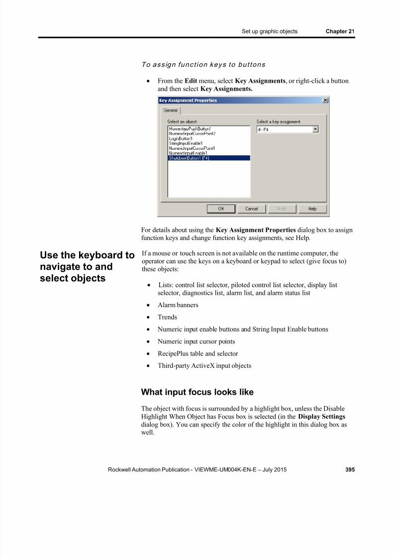
8/15/2019 Factory Talk View ME
http://slidepdf.com/reader/full/factory-talk-view-me 395/635
Set up graphic objects Chapter 21
Rockwell Automation Publication - VIEWME-UM004K-EN-E – July 2015 395
To as s ign func t ion keys to bu t tons
From the Edit menu, select Key Assignments , or right-click a buttonand then select Key Assignments.
For details about using the Key Assignment Properties dialog box to assignfunction keys and change function key assignments, see Help.
If a mouse or touch screen is not available on the runtime computer, theoperator can use the keys on a keyboard or keypad to select (give focus to)these objects:
Lists: control list selector, piloted control list selector, display listselector, diagnostics list, alarm list, and alarm status list
Alarm banners
Trends
Numeric input enable buttons and String Input Enable buttons
Numeric input cursor points
RecipePlus table and selector
Third-party ActiveX input objects
What input focus looks like
The object with focus is surrounded by a highlight box, unless the DisableHighlight When Object has Focus box is selected (in the Display Settings dialog box). You can specify the color of the highlight in this dialog box aswell.
Use the keyboard tonavigate to andselect objects
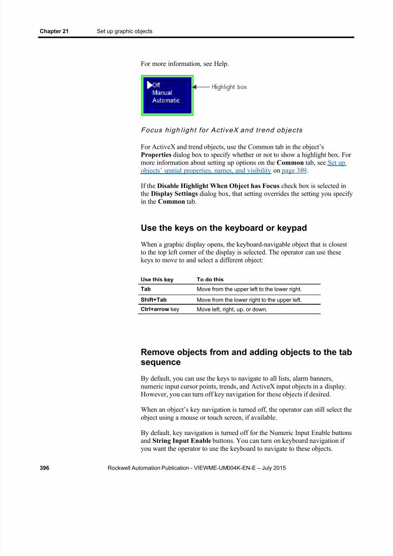
8/15/2019 Factory Talk View ME
http://slidepdf.com/reader/full/factory-talk-view-me 396/635
Chapter 21 Set up graphic objects
396 Rockwell Automation Publication - VIEWME-UM004K-EN-E – July 2015
For more information, see Help.
Focus h igh l ight for Act iveX and t rend objec ts
For ActiveX and trend objects, use the Common tab in the object’sProperties dialog box to specify whether or not to show a highlight box. Formore information about setting up options on the Common tab, see Set upobjects’ spatial properties, names, and visibility on page 389 .
If the Disable Highlight When Object has Focus check box is selected inthe Display Settings dialog box, that setting overrides the setting you specifyin the Common tab.
Use the keys on the keyboard or keypad
When a graphic display opens, the keyboard-navigable object that is closestto the top left corner of the display is selected. The operator can use thesekeys to move to and select a different object:
Use this key To do this
Tab Move from the upper left to the lower right.
Shift+Tab Move from the lower right to the upper left.
Ctrl+arrow key Move left, right, up, or down.
Remove objects from and adding objects to the tabsequence
By default, you can use the keys to navigate to all lists, alarm banners,numeric input cursor points, trends, and ActiveX input objects in a display.However, you can turn off key navigation for these objects if desired.
When an object’s key navigation is turned off, the operator can still select theobject using a mouse or touch screen, if available.
By default, key navigation is turned off for the Numeric Input Enable buttonsand String Input Enable buttons. You can turn on keyboard navigation ifyou want the operator to use the keyboard to navigate to these objects.
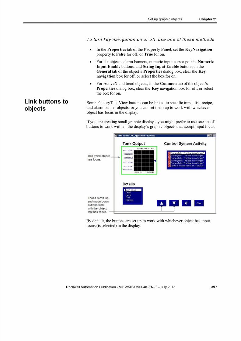
8/15/2019 Factory Talk View ME
http://slidepdf.com/reader/full/factory-talk-view-me 397/635
Set up graphic objects Chapter 21
Rockwell Automation Publication - VIEWME-UM004K-EN-E – July 2015 397
To turn key navigat ion on or o ff , use one of these methods
In the Properties tab of the Property Panel , set the KeyNavigation property to False for off, or True for on.
For list objects, alarm banners, numeric input cursor points, NumericInput Enable buttons, and String Input Enable buttons, in theGeneral tab of the object’s Properties dialog box, clear the Keynavigation box for off, or select the box for on.
For ActiveX and trend objects, in the Common tab of the object’sProperties dialog box, clear the Key navigation box for off, or selectthe box for on.
Some FactoryTalk View buttons can be linked to specific trend, list, recipe,and alarm banner objects, or you can set them up to work with whicheverobject has focus in the display.
If you are creating small graphic displays, you might prefer to use one set of buttons to work with all the display’s graphic objects that accept input focus.
By default, the buttons are set up to work with whichever object has inputfocus (is selected) in the display.
Link buttons toobjects
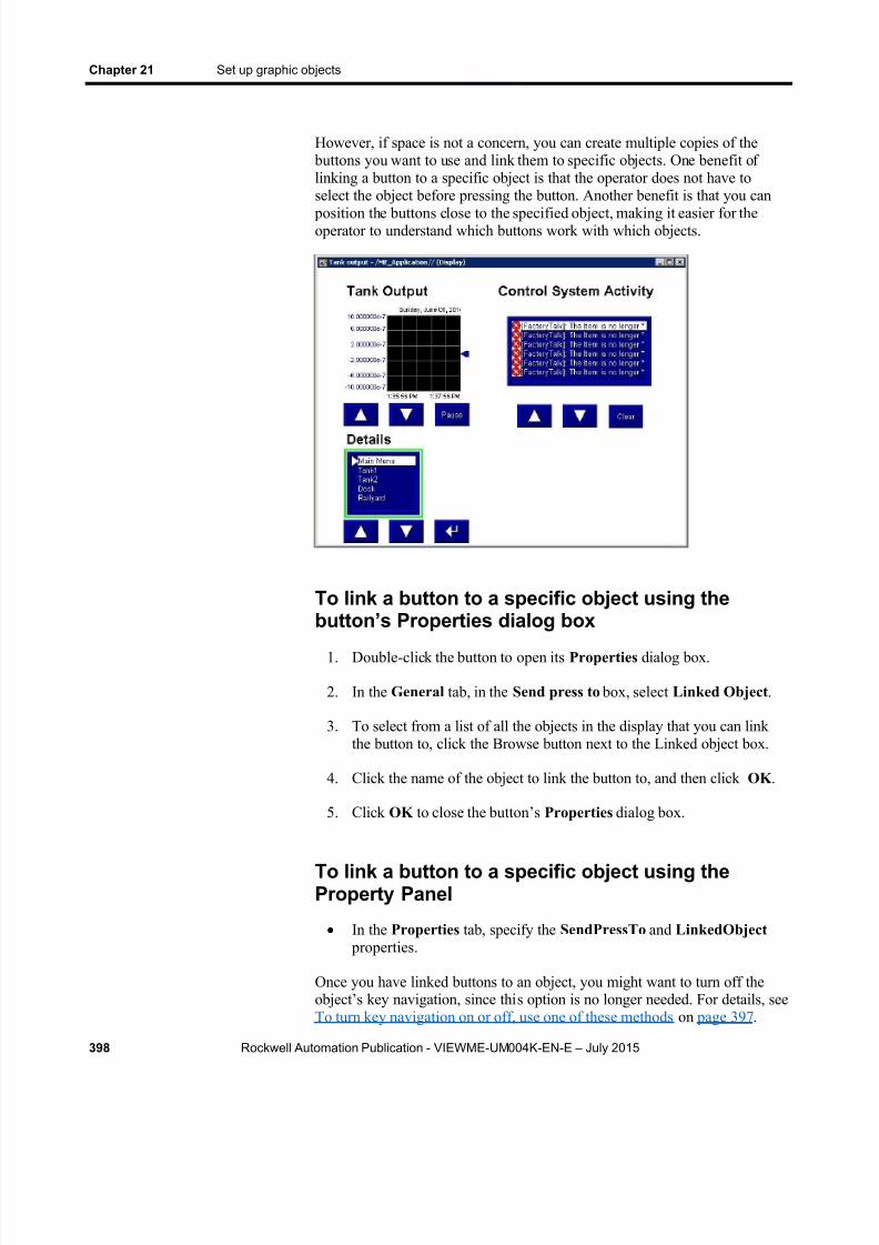
8/15/2019 Factory Talk View ME
http://slidepdf.com/reader/full/factory-talk-view-me 398/635
Chapter 21 Set up graphic objects
398 Rockwell Automation Publication - VIEWME-UM004K-EN-E – July 2015
However, if space is not a concern, you can create multiple copies of the buttons you want to use and link them to specific objects. One benefit oflinking a button to a specific object is that the operator does not have toselect the object before pressing the button. Another benefit is that you can
position the buttons close to the specified object, making it easier for theoperator to understand which buttons work with which objects.
To link a button to a specific object using thebutton’s Properties dialog box
1. Double-click the button to open its Properties dialog box.
2. In the General tab, in the Send press to box, select Linked Object .
3. To select from a list of all the objects in the display that you can linkthe button to, click the Browse button next to the Linked object box.
4. Click the name of the object to link the button to, and then click OK .
5. Click OK to close the button’s Properties dialog box.
To link a button to a specific object using theProperty Panel
In the Properties tab, specify the SendPressTo and LinkedObject properties.
Once you have linked buttons to an object, you might want to turn off theobject’s key navigation, since thi s option is no longer needed. For details, seeTo turn key navigation on or off, use one of these methods on page 397 .
8/15/2019 Factory Talk View ME
http://slidepdf.com/reader/full/factory-talk-view-me 399/635
Set up graphic objects Chapter 21
Rockwell Automation Publication - VIEWME-UM004K-EN-E – July 2015 399
To repeat a button’ s action by pressing and holding it, set up auto repeat forthe button. If you set up auto repeat, when the operator presses and holdsdown the button, repeated button presses are registered until the operatorreleases the button.
A button press occurs when the operator clicks an object with the mouse, presses it on a touch screen, or presses the function key associated with theobject. Auto repeat works with all these methods of pressing buttons.
You can use auto repeat with these buttons:
For this button Each button press does this
Multistate push Sends the value for the next state to the data source. Externalchanges to the Value connection are not recognized when thebutton is in auto repeat mode.
Ramp Sends the new ramped value to the data source. Externalchanges to the Value connection are not recognized when thebutton is in auto repeat mode.
Move up Moves the highlight up an item in the list, recipe selector, orrecipe table, scrolls up in the trend, or ramps the numeric inputcursor point or Numeric Input Enable button value.
Move down Moves the highlight down an item in the list, recipe selector, orrecipe table, scrolls down in the trend, or ramps the numericinput cursor point or Numeric Input Enable button value.
Page up Moves the highlight up a page in the list, recipe selector, orrecipe table.
Page down Moves the highlight down a page in the list, recipe selector, orrecipe table.
Move left Scrolls the trend to the left.
Move right Scrolls the trend to the right.
For each button that uses auto repeat, you can specify these properties:
Auto repeat rate — the number of times per second a button press isregistered when the button goes into auto repeat mode. The default rateis 0, which means that auto repeat is turned off.
Auto repeat delay — the length of time the button has to be pressedand held down before auto repeat starts.
To set up auto repeat for a button, use one of thesemethods
In the Timing tab of the button’s Properties dialog box, specify theAuto repeat rate and Auto repeat delay properties.
In the Properties tab of the Property Panel , specify theAutoRepeatRate and AutoRepeatDelay properties.
Repeat a button’saction by holdingdown the button

8/15/2019 Factory Talk View ME
http://slidepdf.com/reader/full/factory-talk-view-me 400/635
Chapter 21 Set up graphic objects
400 Rockwell Automation Publication - VIEWME-UM004K-EN-E – July 2015
To ensure a value is read by the data source before the operator sends a newvalue, use Enter key handshaking . While Enter key handshaking is ineffect for an object, the operator cannot send a new value to the object’sValue connection.
You can use Enter key handshaking with these graphic objects:
Control list selector
Piloted control list selector
Numeric input enable button
String Input Enable button
Numeric input cursor point
If Enter key handshaking is in effect for one of these objects, the operator
can still provide input to other objects in the graphic display.
If the graphic display is closed while Enter key handshaking is in effect,the handshaking is canceled.
Methods of Enter key handshaking
Enter key handshaking works by setting the object’s Enter connection to 1.As long as the Enter connection is set to 1, new values cannot be sent to theValue connection. How the Enter connection is reset to 0 depends on howyou set up Enter key handshaking .
There are two ways you can use Enter key handshaking :
To hold the value at the data source for a specific period of time.
To hold the value at the data source until the data source notifiesFactoryTalk View that the value has been read.
Choose the method that best suits your application needs and communicationsystem.
Hold the value for a specific period of timeTo set up an object’s Enter key handshaking so that the value at the Valueconnection is held for a specific period of time, assign a tag to the Enter connection and specify the Enter key hold time. You can also specify anEnter key control delay, if desired.
How handshak ing works
This method of Enter key handshaking works as follows:
Ensure values areread by the datasource beforesending new values

8/15/2019 Factory Talk View ME
http://slidepdf.com/reader/full/factory-talk-view-me 401/635
Set up graphic objects Chapter 21
Rockwell Automation Publication - VIEWME-UM004K-EN-E – July 2015 401
1. When the operator presses the Enter button, the value is sent to theValue connection and the Enter key control delay timer beginstiming. (The use of a delay is optional.)
2. If you specify an Enter key control delay, when the time is up, theEnter connection is set to 1. If you don’t use the delay, the Enterconnection is set to 1 as soon as the operator presses Enter .
As long as the Enter connection is set to 1, the operator cannot sendnew values to the data source.
3. When the Enter connection is set to 1, the Enter key hold time timer begins timing.
4. When the Enter key hold time has expired, the Enter connection isreset to 0 and the operator can send a new value to the Value
connection.
To se t up Enter key handshaking to ho ld the va lue for aspeci f ic per iod of t ime
1. In Timing tab of the object’s Properties dialog box, specify the Enterkey control dela y (optional) and Enter key hold time properties.
2. In the Connections tab, assign a tag to the Enter connection. A digitaltag is recommended (either an HMI tag or a data server tag).
You can also use the Property Panel to specify the properties and assign atag to the Enter connection.
Hold the value until it is acknowledged
To set up an object’s Enter key handshaking so that the value at the Valueconnection is held until the data source notifies FactoryTalk View that it hasread the value, use two connections: the Enter connection and the Enterhandshake connection.
Instead of using an Enter key hold time , specify an Enter key handshake
time . You must also specify the Handshake reset type. You can use an Enterkey control delay , if desired.
How the Handshake rese t type works
How the Enter handshake connection resets the Enter connection dependson which Handshake reset type you select:
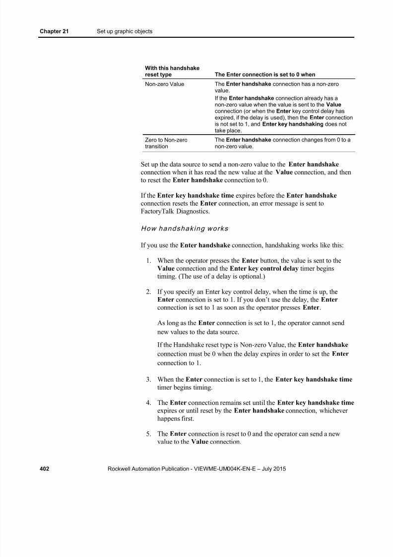
8/15/2019 Factory Talk View ME
http://slidepdf.com/reader/full/factory-talk-view-me 402/635
Chapter 21 Set up graphic objects
402 Rockwell Automation Publication - VIEWME-UM004K-EN-E – July 2015
With this handshakereset type The Enter connection is set to 0 when
Non-zero Value The Enter handshake connection has a non-zerovalue.If the Enter handshake connection already has anon-zero value when the value is sent to the Valueconnection (or when the Enter key control delay hasexpired, if the delay is used), then the Enter connectionis not set to 1, and Enter key handshaking does nottake place.
Zero to Non-zerotransition
The Enter handshake connection changes from 0 to anon-zero value.
Set up the data source to send a non-zero value to the Enter handshakeconnection when it has read the new value at the Value connection, and thento reset the Enter handshake connection to 0.
If the Enter key handshake time expires before the Enter handshakeconnection resets the Enter connection, an error message is sent toFactoryTalk Diagnostics.
How handshak ing works
If you use the Enter handshake connection, handshaking works like this:
1. When the operator presses the Enter button, the value is sent to theValue connection and the Enter key control delay timer beginstiming. (The use of a delay is optional.)
2. If you specify an Enter key control delay, when the time is up, theEnter connection is set to 1. If you don’t use the delay, the Enterconnection is set to 1 as soon as the operator presses Enter .
As long as the Enter connection is set to 1, the operator cannot sendnew values to the data source.
If the Handshake reset type is Non-zero Value, the Enter handshakeconnection must be 0 when the delay expires in order to set the Enterconnection to 1.
3. When the Enter connection is set to 1, the Enter key handshake time timer begins timing.
4. The Enter connection remains set until the Enter key handshake time expires or until reset by the Enter handshake connection, whicheverhappens first.
5. The Enter connection is reset to 0 and the operator can send a newvalue to the Value connection.

8/15/2019 Factory Talk View ME
http://slidepdf.com/reader/full/factory-talk-view-me 403/635
Set up graphic objects Chapter 21
Rockwell Automation Publication - VIEWME-UM004K-EN-E – July 2015 403
To se t up Enter key handshaking to ho ld the va lue unt i l thedata source has read i t
1. In the Timing tab of the object’s Properties dialog box, specify these properties:
Enter key control delay (optional)
Enter key handshake time
Handshake reset type
2. In the Connections tab, assign these connections:
Enter — assign a tag. A digital tag is recommended (either anHMI tag or a data server tag).
Enter handshake — assign a tag or expression.
3. Set up the data source to send a non-zero value to the Enterhandshake connection when it has read the new value at the Valueconnection, and then to reset the Enter handshake connection to 0.
You can also use the Property Panel to specify the properties and assigntags to the connections.
Graphic objects use the time, date, and number format of the currentapplication language. For example, if the application language uses a commafor the decimal symbol, floating-point values shown in graphic objects uses a
comma for the decimal symbol.
For information about using multiple languages, see Set up languageswitching on page 197 .
Many of the button graphic objects are set up the same way. The instructionsin this section apply to the following buttons:
Alarm status mode
Backspace
Clear alarm banner
Clear alarm history
Diagnostics clear
Diagnostics clear all
Display print
End
Enter
Goto configure mode
Time, date, andnumber formats for
graphic objects
Set up buttons

8/15/2019 Factory Talk View ME
http://slidepdf.com/reader/full/factory-talk-view-me 404/635
Chapter 21 Set up graphic objects
404 Rockwell Automation Publication - VIEWME-UM004K-EN-E – July 2015
Home
Information acknowledge
Language Switch
Login
Logout
Move down
Move left
Move right
Move up
Next pen
Page down
Page up
Password
Pause
RecipePlus
Reset alarm status
Return to display
Shutdown
Silence alarms Sort alarms
You can set up any combination of these buttons in a graphic display. Forexample, you might want to put a login, logout, and shutdown button in thesame graphic display.
Create and then set up each button separately.
The illustration shows the login button. Some buttons have different properties on the General tab, but you can use these instructions to set up anyof the buttons in the list. For example, on the General tab for the
acknowledge all alarms button and the clear alarm history button, you canspecify a subset of alarms to which the button’s action applies. For detailsabout filtering alarm triggers, see Filter alarm triggers in multiple languages on page 123 .

8/15/2019 Factory Talk View ME
http://slidepdf.com/reader/full/factory-talk-view-me 405/635
Set up graphic objects Chapter 21
Rockwell Automation Publication - VIEWME-UM004K-EN-E – July 2015 405
To set up a button
1. Double-click the button.
2. In the button’s Properties dialog box, fill in the options on each tab:
In the General tab, specify what the button looks like at run time.For some buttons, you can specify whether to link the button to aspecific object. For the logout button, you can specify a display toopen when the button is pressed, and whether the display will use a
parameter file or list when it opens.
In the Label tab, specify what text or image to show on the button.
In the Timing tab, set up whether or not the button press repeatsautomatically when the operator presses and holds the buttondown. You can also set up the rate at which the button press
repeats. For more information about auto repeat, see To set up autorepeat for a button, use one of these methods on page 399 .
In the Common tab, specify the button’s spacial properties, name,and visibility.
For details about the options in the tabs, see Help.
3. When you are finished, click OK .
8/15/2019 Factory Talk View ME
http://slidepdf.com/reader/full/factory-talk-view-me 406/635
Chapter 21 Set up graphic objects
406 Rockwell Automation Publication - VIEWME-UM004K-EN-E – July 2015
Buttons described later in the chapter
Information about setting up the following buttons is described later in thechapter:
Close display
Goto display
Interlocked push
Latched push
Macro
Maintained push
Momentary push
Multistate push Numeric input enable
Print alarm history
Print alarm status
Ramp
String Input Enable
Push buttons start or stop processes or actions by changing tag values.
Important: Never use push buttons for emergency stops.Emergency stop buttons must always behard-wired.
You can use different kinds of push buttons, depending on what kind ofmachinery you are running or process you are controlling:
Momentary push buttons change a tag to one value when the buttonis pressed, and another value when the button is released. The machineis on only while the button is held down. When the button is released,the machine turns off. Momentary push buttons are useful for jogging amotor, and they can be set up to start and stop a machine or process.
Maintained push buttons toggle between two values. This type of button is useful for changing a setting within a machine or process, butnot for starting the machine or process. For example, use theMaintained push button for changing modes, such as Auto to Manual,or Metric to Imperial.
Latched push buttons latch in the on position, and must be unlatched by another button or process to return to the off position. This type of button is useful for starting a machine or process.
How to use pushbuttons

8/15/2019 Factory Talk View ME
http://slidepdf.com/reader/full/factory-talk-view-me 407/635
Set up graphic objects Chapter 21
Rockwell Automation Publication - VIEWME-UM004K-EN-E – July 2015 407
Multistate push buttons allow an operator to cycle through multipleoptions consecutively, using a single button. The current state of a
process or operation is shown on the button by a different color,caption, or image for each state.
Interlocked push buttons work in groups, and share the same tag.Pressing one button cancels another. Although Interlocked push
buttons work as a group, you add them to the display one at a time.
Ramp buttons increase or decrease the value of a tag by either aninteger or floating-point value. You can use two Ramp buttons togetherto create an increment/decrement control, for example for the speed ofa motor. Or, you can use a Numeric Input Enable button or numericinput cursor point.
For information about the Numeric Input Enable button, see Set up Numeric Input Enable buttons on page 418 .
For information about the numeric input cursor point, see Set up numericinput cursor points on page 420 .
Use the Momentary push button to start a process or action. When pressed,the button changes a tag to one value, and when released, the button changesthe tag to another value.
The Momentary push button’s states can perform one of three kinds ofactions:
Change the Value connection to 1 when the button is pressed, and to 0
when the button is released. This kind of button is called normallyopen , because its released state is off. Pressing the button completesthe circuit.
Change the Value connection to 0 when the button is pressed, and to 1when the button is released. This kind of button is called normallyclosed , because its released state is on. Pressing the button breaks thecircuit.
Change the Value connection to a value you specify. You assign thedes ired values to the button’s press and release actions. For example,50 when pressed, and 100 when released.
The error state
The button’s error state is shown at run time when:
The Value connection is unassigned.
The Indicator connection value does not match one of the state valuesyou set up.
Set up Momentarypush buttons

8/15/2019 Factory Talk View ME
http://slidepdf.com/reader/full/factory-talk-view-me 408/635
Chapter 21 Set up graphic objects
408 Rockwell Automation Publication - VIEWME-UM004K-EN-E – July 2015
To set up a Momentary push button
1. Double-click the Momentary push button.
2. In the button’s Properties dialog box, fill in the options on each tab:
In the General tab, specify what the button looks like at run time,and what type of action the button performs.
In the States tab, specify what the button looks like when it is pressed and released at run time. For tips about setting up states,see Tips for setting up objects with states on page 390 .
In the Common tab, specify the button’s spacial properties, name,and visibility.
In the Connections tab, specify the tags or expression with whichthe button exchanges data. For information, see Assign tags andexpressions to graphic objects on page 366 .
3. For details about the options in the tabs, see Help.
4. When you are finished, click OK .
Use the Maintained push button to change a setting in a machine or process.Maintained push buttons are not useful for starting or stopping a machine or
process.
Set up Maintainedpush buttons
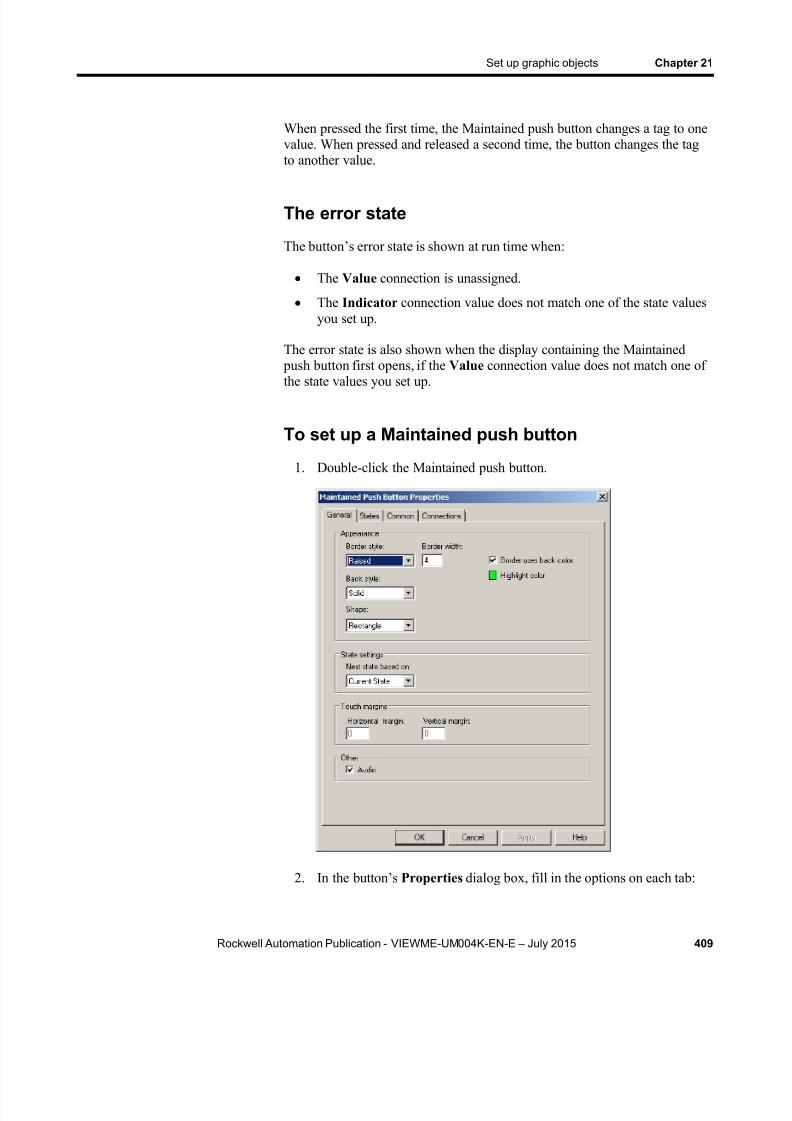
8/15/2019 Factory Talk View ME
http://slidepdf.com/reader/full/factory-talk-view-me 409/635
Set up graphic objects Chapter 21
Rockwell Automation Publication - VIEWME-UM004K-EN-E – July 2015 409
When pressed the first time, the Maintained push button changes a tag to onevalue. When pressed and released a second time, the button changes the tagto another value.
The error state
The button’s error state is shown at run time when:
The Value connection is unassigned.
The Indicator connection value does not match one of the state valuesyou set up.
The error state is also shown when the display containing the Maintained push button first opens, if the Value connection value does not match one of
the state values you set up.
To set up a Maintained push button
1. Double-click the Maintained push button.
2. In the button’s Properties dialog box, fill in the options on each tab:
8/15/2019 Factory Talk View ME
http://slidepdf.com/reader/full/factory-talk-view-me 410/635
Chapter 21 Set up graphic objects
410 Rockwell Automation Publication - VIEWME-UM004K-EN-E – July 2015
In the General tab, specify what the button looks like at run time,and how the button changes state.
In the States tab, specify what the button looks like when it is
pressed and released at run time. For tips about setting up states,see Tips for setting up objects with states on page 390 .
In the Common tab, specify the button’s spacial properties, name,and visibility.
In the Connections tab, specify the tags or expression with whichthe button exchanges data. For information, see Assign tags andexpressions to graphic objects on page 366 .
For details about the options in the tabs, see Help.
3. When you are finished, click OK .
The Latched push button latches in the On position, and must be unlatched by another button or process to return to the Off position. This type of buttonis useful for starting a machine or process.
For example, use the Latched push button when you want the Valueconnection to start a process within a programmable controller and remainset until the process is completed. You can also use a Latched push buttonwhen you have a controller with a long program or long update times.
When the operator presses a Latched push button, it changes the Valueconnection to one value, and remains at that value until the Handshake connection gives the signal to unlatch the button.
The error state
The button’s error state is shown at run time when:
The Value connection is unassigned.
The Indicator connection value does not match one of the state valuesyou set up.
The Handshake connection is unassigned.
The error state is also shown when the display containing the Latched push button first opens, if the Value connection value does not match one of thestate values you set up.
Set up Latchedpush buttons
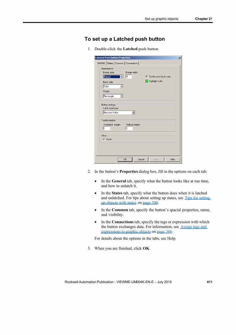
8/15/2019 Factory Talk View ME
http://slidepdf.com/reader/full/factory-talk-view-me 411/635
Set up graphic objects Chapter 21
Rockwell Automation Publication - VIEWME-UM004K-EN-E – July 2015 411
To set up a Latched push button
1. Double-click the Latched push button.
2. In the button’s Properties dialog box, fill in the options on each tab:
In the General tab, specify what the button looks like at run time,and how to unlatch it.
In the States tab, specify what the button does when it is latchedand unlatched. For tips about setting up states, see Tips for settingup objects with states on page 390 .
In the Common tab, specify the button’ s spacial properties, name,and visibility.
In the Connections tab, specify the tags or expression with whichthe button exchanges data. For information, see Assign tags andexpressions to graphic objects on page 366 .
For details about the options in the tabs, see Help.
3. When you are finished, click OK .

8/15/2019 Factory Talk View ME
http://slidepdf.com/reader/full/factory-talk-view-me 412/635
Chapter 21 Set up graphic objects
412 Rockwell Automation Publication - VIEWME-UM004K-EN-E – July 2015
The Multistate push button displays and allows an operator to cycle throughmultiple options consecutively. The Multistate push button displays thecurrent state of a process or operation by showing a different color, caption,or image to reflect different states.
Each time the operator presses the button, the tag changes to the value for thenext state. When the button is in its last state and the operator presses the
button, the button returns to its first state.
The error state
The button’s error state is shown at run time when:
The Value connection is unassigned.
The Indicator connection value does not match one of the state valuesyou set up.
The error state is also shown when the display containing the Multistate push button first opens, if the Value connection value does not match one of thestate values you set up.
Set up Multistatepush buttons

8/15/2019 Factory Talk View ME
http://slidepdf.com/reader/full/factory-talk-view-me 413/635
Set up graphic objects Chapter 21
Rockwell Automation Publication - VIEWME-UM004K-EN-E – July 2015 413
To set up a Multistate push button
1. Double-click the Multistate push button.
2. In the button’s Properties dialog box, fill in the options on each tab:
In the General tab, specify what the button looks like at run time,and how the button changes state.
In the States tab, specify what the button does when it is pressedand released. For tips about setting up states, see Tips for settingup objects with states on page 390 .
In the Timing tab, set up whether or not the button press repeatsautomatically when the operator presses and holds the buttondown. You can also set up the rate at which the button pressrepeats. For more information about auto repeat, see Repeat a
button’s action by holding down the button on page 399 . In the Common tab, specify the button’s spacial properties, name,
and visibility.
In the Connections tab, specify the tags or expression with whichthe button exchanges data. For information, see Assign tags andexpressions to graphic objects on page 366 .
For details about the options in the tabs, see Help.

8/15/2019 Factory Talk View ME
http://slidepdf.com/reader/full/factory-talk-view-me 414/635
Chapter 21 Set up graphic objects
414 Rockwell Automation Publication - VIEWME-UM004K-EN-E – July 2015
3. When you are finished, click OK .
Multiple Interlocked push buttons work together and share the same tag.Pressing one button cancels another. Although Interlocked push buttons
work as a group, you add them to the display one at a time.
When the operator presses one of the Interlocked push buttons, the tagassigned to its Value connection changes to one value. When the operator
presses a different Interlocked push button, the tag changes to another value.Assign the same tag to each button’s Value connection.
You can also use a single Interlocked push button to send a value to a tag.
To set up an Interlocked push button
1. Double-click the Interlocked push button.
2. In the button’s Properties dialog box, fill in the options on each tab:
Set up Interlocked
push buttons

8/15/2019 Factory Talk View ME
http://slidepdf.com/reader/full/factory-talk-view-me 415/635
Set up graphic objects Chapter 21
Rockwell Automation Publication - VIEWME-UM004K-EN-E – July 2015 415
In the General tab, specify what the button looks like at run time,and the value it sends to the Value connection.
In the States tab, specify what the button looks like when it is
pressed and released at run time. For tips about setting up states,see Tips for setting up objects with states on page 390 .
In the Common tab, specify the button’s spacial properties, name,and visibility.
In the Connections tab, specify the tag with which the buttonexchanges data. Interlocked push buttons have no Indicator connection. For information, see Assign tags and expressions tographic objects on page 366 .
For details about the options in the tabs, see Help.
3. When you are finished, click OK .
Use the Ramp button to increase or decrease the value of a tag.
Ramp buttons can change a tag by either an integer or floating-point value.You can use two Ramp buttons together to create an increment/decrementcontrol.
Each time the operator presses the button, the tag value increases ordecreases, depending on how you set up the button.
Set up Rampbuttons

8/15/2019 Factory Talk View ME
http://slidepdf.com/reader/full/factory-talk-view-me 416/635
Chapter 21 Set up graphic objects
416 Rockwell Automation Publication - VIEWME-UM004K-EN-E – July 2015
To set up a Ramp button
1. Double-click the Ramp button.
2. In the button’s Properties dialog box, fill in the options on each tab:
In the General tab, specify what the button looks like at run time,whether the button uses variable or constant upper and lower limitsand ramp value, and whether the button ramps a value up or down.
In the Label tab, specify what text or image to show on the button.
In the Timing tab, set up whether or not the button press repeatsautomatically when the operator presses and holds the buttondown, and the rate at which the button press repeats. For moreinformation about auto repeat, see Repeat a button’s action byholding down the button on page 399 .
In the Common tab, specify the button’s spacial properties, name,and visibility.
In the Connections tab, specify the tag with which the buttonexchanges data. If variable ramp and limit values are selected inthe General tab, assign tags or expressions to the Ramp and Limitconnections. Ramp buttons have no Indicator connection. Forinformation about assigning tags, see Assign tags and expressionsto graphic objects on page 366 .
For details about the options in the tabs, see Help.

8/15/2019 Factory Talk View ME
http://slidepdf.com/reader/full/factory-talk-view-me 417/635
Set up graphic objects Chapter 21
Rockwell Automation Publication - VIEWME-UM004K-EN-E – July 2015 417
3. When you are finished, click OK .
Use the numeric display object to show the operator numeric informationfrom the data source. For example, you might use a numeric display to show
the current temperature of an oven.
How values are shown
The numeric display shows the value of the Value connection at the datasource. The value shown depends on whether the Value connection value is afloating-point number or an integer. Integer values are shown as is.Floating-point values are rounded to fit the display. The decimal placesoption also affects how floating point numbers are shown.
For example, if the numeric display is set up to show 6 digits, with onedecimal place, 1234.56 is rounded to 1234.6. 1234.44 is rounded to 1234.4.The decimal counts as one of the digits.
For more information about how values are rounded, see How values arerounded on page 98 .
Problems with showing values
If the Value connection is unassigned, the numeric display is filledwith asterisks (*).
If the integer portion of the value, including the decimal point andminus sign, contains more digits than specified for the display, thenumeric display is filled with asterisks.
If the numeric display is sized so that the value cannot be fully shown,the value is truncated and the last showable digit is replaced with anasterisk.
If the value does not fit on the first line of the display, and there isroom for a second line, the value continues onto the second line.
Set up numeric
displays

8/15/2019 Factory Talk View ME
http://slidepdf.com/reader/full/factory-talk-view-me 418/635
Chapter 21 Set up graphic objects
418 Rockwell Automation Publication - VIEWME-UM004K-EN-E – July 2015
To se t up a numer ic d isplay
1. Double-click the numeric display.
2. In the object’s Properties dialog box, fill in the options on each tab:
In the General tab, specify what the button looks like at run time.
In the Common tab, specify the button’s spacial properties, name,and visibility.
In the Connections tab, specify the tags or expression whose datais shown. For information, see Assign tags and expressions tographic objects on page 366 .
For details about the options in the tabs, see Help.
3. When you are finished, click OK .
The operator can press the Numeric Input Enable button to open a numeric pop-up keypad or scratchpad, enter a number in the keypad or scratchpad,and then send the number to the data source.
For more information about using the Numeric Input Enable button at runtime, see Add a user or group on page 270 .
You can also set up the Numeric Input Enable button to work as a Ramp button. In this case, when the button has focus, the operator can press a move
Set up NumericInput Enablebuttons
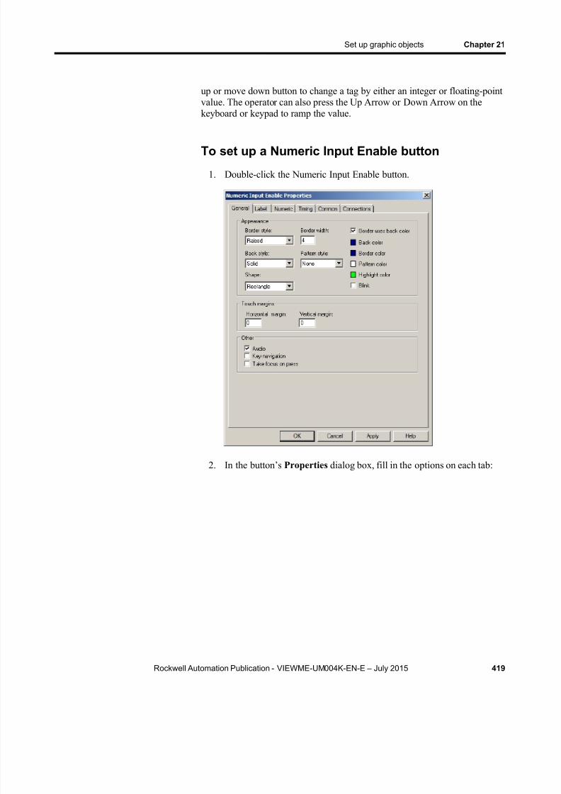
8/15/2019 Factory Talk View ME
http://slidepdf.com/reader/full/factory-talk-view-me 419/635
Set up graphic objects Chapter 21
Rockwell Automation Publication - VIEWME-UM004K-EN-E – July 2015 419
up or move down button to change a tag by either an integer or floating-pointvalue. The operator can also press the Up Arrow or Down Arrow on thekeyboard or keypad to ramp the value.
To set up a Numeric Input Enable button
1. Double-click the Numeric Input Enable button.
2. In the button’s Properties dialog box, fill in the options on each tab:
8/15/2019 Factory Talk View ME
http://slidepdf.com/reader/full/factory-talk-view-me 420/635
Chapter 21 Set up graphic objects
420 Rockwell Automation Publication - VIEWME-UM004K-EN-E – July 2015
In the General tab, specify what the button looks like at run time,whether the operator can navigate to the button using the keys onthe keyboard or keypad, and whether the operator can press the
button to give it focus.
In the Label tab, specify what text or image to show on the buttonThe same text will appear as a caption on the top of the pop-up thatopens when the button is pressed at run time.
In the Numeric tab, set up which pop-up window opens (if any),the ramp value (if any), minimum and maximum values to send tothe data source, whether the minimum and maximum values will
be variable (from tags or expressions) or constant, and decimal point settings.
In the Timing tab, set up the timing and handshake settings for theEnter key. These settings do not apply when you ramp a value.
For information about using Enter key handshaking , see Methodsof Enter key handshaking on page 400 .
In the Common tab, specify the button’s spacial properties, name,and visibility.
In the Connections tab, specify the tags or expressions with whichthe button exchanges data. For information, see Assign tags andexpressions to graphic objects on page 366 .
For details about the options in the tabs, see Help.
3. When you are finished, click OK .
The operator can activate the numeric input cursor point to open a numeric pop-up keypad or scratchpad. The operator can enter a number in the keypador scratchpad, and then send the number to the data source. The cursor pointshows the current value at the data source (if you assign a tag to theIndicator connection).
For more information about using the numeric input cursor point at run time,see Add a user or group on page 270 .
You can also set up the numeric input cursor point to work as a Ramp button.In this case, when the cursor point has focus, the operator can press a moveup or move down button to change a tag by either an integer or floating-point
value. The operator can also press the Up Arrow or Down Arrow on thekeyboard or keypad to ramp the value.
Set up numericinput cursor points

8/15/2019 Factory Talk View ME
http://slidepdf.com/reader/full/factory-talk-view-me 421/635
Set up graphic objects Chapter 21
Rockwell Automation Publication - VIEWME-UM004K-EN-E – July 2015 421
To set up a numeric input cursor point
1. Double-click the numeric input cursor point.
2. In the object’s Properties dialog box, fill in the options on each tab:

8/15/2019 Factory Talk View ME
http://slidepdf.com/reader/full/factory-talk-view-me 422/635
Chapter 21 Set up graphic objects
422 Rockwell Automation Publication - VIEWME-UM004K-EN-E – July 2015
In the General tab, specify what the cursor point looks like at runtime, and whether the operator can navigate to the cursor pointusing the keys on the keyboard or keypad.
In the Numeric tab, set up which pop-up window opens (if any),what caption (if any) will be shown on the pop-up, the ramp value(if any), minimum and maximum values to send to the data source,whether the minimum and maximum values will be variable (fromtags or expressions) or constant, decimal point settings, and displaysettings.
In the Timing tab, set up the timing and handshake settings for theEnter key. These settings do not apply when you ramp values. Forinformation about using Enter key handshaking , see Methods ofEnter key handshaking on page 400 .
In the Common tab, specify the button’s spacial properties, name,
and visibility. In the Connections tab, specify the tags or expression with which
the numeric input cursor point exchanges data. For information,see Assign tags and expressions to graphic objects on page 366 .
For details about the options in the tabs, see Help.
3. When you are finished, click OK .
Use the string display object to show the operator messages from the datasource. For example, you might set up the data source to generate strings thatreport on the state of a process or operation, or that provide instructions
about what the operator needs to do next. At run time, the display shows theoperator the string value of the Value connection at the data source.
How values are shown
If the Value connection is unassigned, the string display is blank.
FactoryTalk View shows the number of characters (bytes) specified forthe tag assigned to the Value connection.
Set up stringdisplays

8/15/2019 Factory Talk View ME
http://slidepdf.com/reader/full/factory-talk-view-me 423/635
Set up graphic objects Chapter 21
Rockwell Automation Publication - VIEWME-UM004K-EN-E – July 2015 423
To se t up a s t r ing d isplay
1. Double-click the string display.
2. In the object’s Properties dialog box, fill in the options on each tab:
In the General tab, specify what the string display looks like at runtime.
In the Common tab, specify the string display’s spacial properties,name, and visibility.
In the Connections tab, specify the tag or expression whose data isshown. For information, see Assign tags and expressions to graphicobjects on page 366 .
For details about the options in the tabs, see Help.
3. When you are finished, click OK .
The operator can press the String Input Enable button to open a string pop-up scratchpad or keyboard. The operator can enter text in the scratchpador keyboard, and then send the string to the data source.
For more information about using the String Input Enable button at runtime, see Add a user or group on page 270 .
Set up String InputEnable buttons

8/15/2019 Factory Talk View ME
http://slidepdf.com/reader/full/factory-talk-view-me 424/635
Chapter 21 Set up graphic objects
424 Rockwell Automation Publication - VIEWME-UM004K-EN-E – July 2015
To set up a String Input Enable button
1. Double-click the String Input Enable button.
2. In the button’s Properties dialog box, fill in the options on each tab:
In the General tab, specify what the button looks like at run time,whether the operator can navigate to the button using the keys onthe keyboard or keypad, and whether the operator can press the
button to give it focus.
In the Label tab, specify what text or image to show on the button.
The same text will appear as a caption on the pop-up that appearswhen the button is pressed at run time.
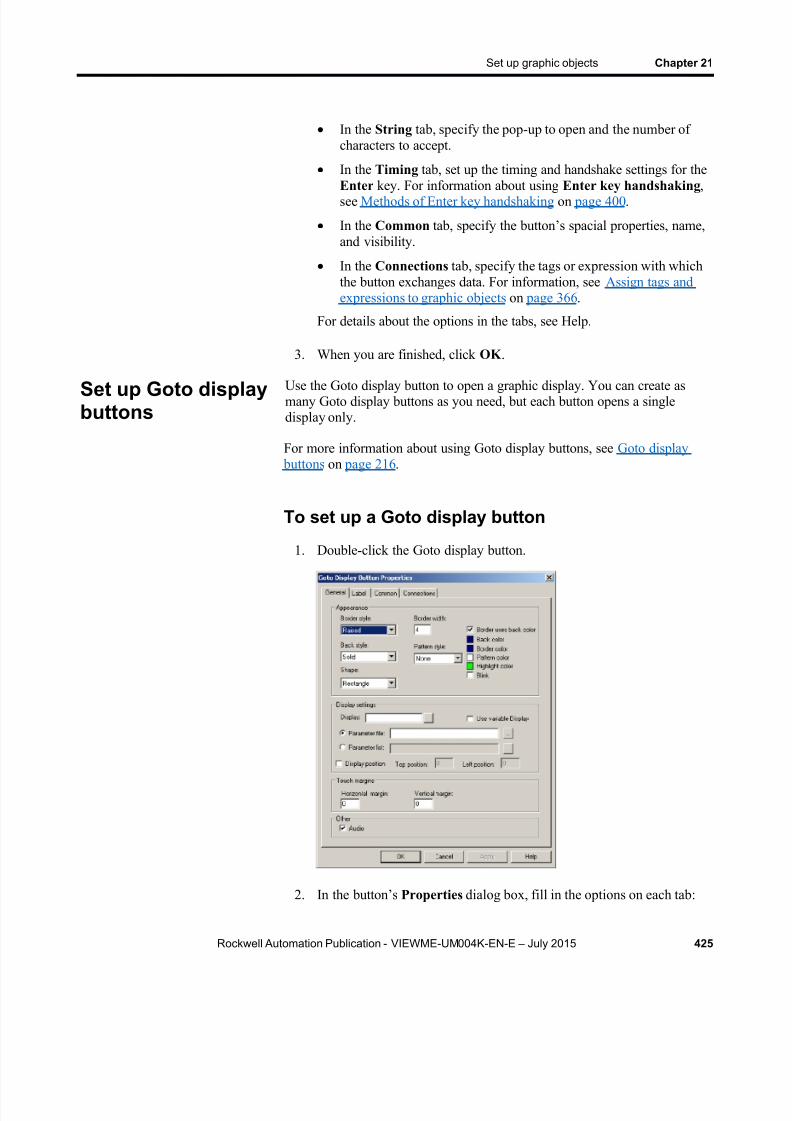
8/15/2019 Factory Talk View ME
http://slidepdf.com/reader/full/factory-talk-view-me 425/635
Set up graphic objects Chapter 21
Rockwell Automation Publication - VIEWME-UM004K-EN-E – July 2015 425
In the String tab, specify the pop-up to open and the number ofcharacters to accept.
In the Timing tab, set up the timing and handshake settings for the
Enter key. For information about using Enter key handshaking ,see Methods of Enter key handshaking on page 400 .
In the Common tab, specify the button’s spacial properties, name,and visibility.
In the Connections tab, specify the tags or expression with whichthe button exchanges data. For information, see Assign tags andexpressions to graphic objects on page 366 .
For details about the options in the tabs, see Help.
3. When you are finished, click OK .
Use the Goto display button to open a graphic display. You can create asmany Goto display buttons as you need, but each button opens a singledisplay only.
For more information about using Goto display buttons, see Goto display buttons on page 216 .
To set up a Goto display button
1. Double-click the Goto display button.
2. In the button’s Properties dialog box, fill in the options on each tab:
Set up Goto displaybuttons

8/15/2019 Factory Talk View ME
http://slidepdf.com/reader/full/factory-talk-view-me 426/635
Chapter 21 Set up graphic objects
426 Rockwell Automation Publication - VIEWME-UM004K-EN-E – July 2015
In the General tab, specify what the button looks like at run time,the display to open, and the parameter file or parameter list to use,if any.
In the Label tab, specify what text or image to show on the button. In the Common tab, specify the button’ s spacial properties, name,
and visibility.
In the Connections tab, assign a tags or expressions as needed.
For details about the options in the tabs, see Help.
3. When you are finished, click OK .
When the operator presses a close display button at run time, the graphicdisplay that the button is on closes. You can set up the button to write out avalue when the display closes.
For more information about using close display buttons, see Close display buttons on page 218 .
To set up a Close Display button
1. Double-click the button.
2. In the button’s Properties dialog box, fill in the options on each tab:
Set up close displaybuttons

8/15/2019 Factory Talk View ME
http://slidepdf.com/reader/full/factory-talk-view-me 427/635
Set up graphic objects Chapter 21
Rockwell Automation Publication - VIEWME-UM004K-EN-E – July 2015 427
In the General tab, specify what the button looks like at run time,and whether to write out a value when the display closes.
In the Label tab, specify what text or image to show on the button.
In the Common tab, specify the button’s spacial properties, name,and visibility.
In the Connections tab, specify the tag with which the buttonexchanges data. For information, see Assign tags and expressionsto graphic objects on page 366 .
For details about the options in the tabs, see Help.
3. When you are finished, click OK .
The display list selector is a list of graphic shows in the application. Eachgraphic display is represented by a different state in the display list selector.An operator can scroll through the list of displays, and then select the displayto open by pressing an Enter button, or Enter key.
For more information about using display list selectors, see Display listselectors on page 218 .
To set up a display list selector
1. Double-click the display list selector.
Set up display list
selectors

8/15/2019 Factory Talk View ME
http://slidepdf.com/reader/full/factory-talk-view-me 428/635
Chapter 21 Set up graphic objects
428 Rockwell Automation Publication - VIEWME-UM004K-EN-E – July 2015
2. In the object’s Properties dialog box, fill in the options on each tab:
In the General tab, specify what the selector looks like at run time,its number of states, whether the operator can navigate to the
selector using the keys on the keyboard or keypad, and whether thecursor wraps from the bottom of the list back to the top.
In the States tab, specify which graphic display to use for each ofthe display list selector’s states, whether the display will use a
parameter file or list when it opens, its opening position, and howeach graphic display is named in the list. For tips about setting upstates, see Tips for setting up objects with states on page 390 .
In the Common tab, specify the display list selector’s spacial properties, name, and visibility.
For details about the options in the tabs, see Help.
3. When you are finished, click OK .
Indicators show the status of processes or operations by showing differentcolors, captions, or images to reflect different states.
You can create different kinds of indicators to suit your needs:
Multistate indicators show the current state of a process or operation by showing a different color, caption, or image to reflect differentstates.
Symbols show a symbol that changes color to indicate the state of a
process or operation. This allows the operator to see the status of a process or operation at a glance.
List indicators show a list of states for a process or operation, andhighlight the current state. Each state is represented by a caption in thelist. This type of indicator is useful if you want operators to view thecurrent state, but also see the other possible states. For sequential
processes, the list can inform the operator about what happens next.
The multistate indicator shows the current state of a process or operation byshowing a different color, caption, or image for each state.
The error state
The multistate indicator’s error state is shown at run time when:
The Indicator connection is unassigned.
The Indicator connection’s value does not match one of the statevalues you set up.
How to useindicators
Set up multistateindicators

8/15/2019 Factory Talk View ME
http://slidepdf.com/reader/full/factory-talk-view-me 429/635
Set up graphic objects Chapter 21
Rockwell Automation Publication - VIEWME-UM004K-EN-E – July 2015 429
The Trigger type is set to Value , and the Indicator connection valuedoes not match one of the state values you set up.
The Trigger type is set to LSB , and the position of the least significant
bit set in the Value connection does not match one of the state valuesyou set up.
The Trigger type is set to Value , and an array tag has been assigned tothe object’s Value connection.
To set up a multistate indicator
1. Double-click the multistate indicator.
2. In the object’s Properties dialog box, fill in the options on each tab:

8/15/2019 Factory Talk View ME
http://slidepdf.com/reader/full/factory-talk-view-me 430/635
Chapter 21 Set up graphic objects
430 Rockwell Automation Publication - VIEWME-UM004K-EN-E – July 2015
In the General tab, specify what the indicator looks like, and thenumber of states for the indicator.
In the States tab, specify how the indica tor’s appearance changes
when its tag or expression’s value changes. For tips about settingup states, see Tips for setting up objects with states on page 390 .
In the Common tab, specify the indicator’ s spacial properties,name, and visibility.
In the Connections tab, specify the tag or expression from whichthe indicator receives data. For information, see Assign tags andexpressions to graphic objects on page 366 .
For details about the options in the tabs, see Help.
3. When you are finished, click OK .
The symbol is an indicator that shows a single monochrome image thatchanges color to match the state of a process or operation. This allows theoperator to see the status of a process or operation at a glance.
The error state
The symbol’s error state is shown at run time when:
The Indicator connection is unassigned.
The Indicator connection’s value does not match one of the state
values you set up. The Trigger type is set to Value , and the Indicator connection value
does not match one of the state values you set up.
The Trigger type is set to LSB , and the position of the least significant bit set in the Value connection does not match one of the state valuesyou set up.
The Trigger type is set to Value , and an array tag has been assigned tothe object’s Value connection.
Set up symbols

8/15/2019 Factory Talk View ME
http://slidepdf.com/reader/full/factory-talk-view-me 431/635
Set up graphic objects Chapter 21
Rockwell Automation Publication - VIEWME-UM004K-EN-E – July 2015 431
To set up a symbol
1. Double-click the symbol.
2. In the object’s Properties dialog box, fill in the options on each tab:
In the General tab, specify what the symbol looks like at run time,and the number of states for the symbol.
In the States tab, specify how the symbol’s appearance changeswhen its tag or expression’s value changes. For tips about settingup states, see Tips for setting up objects with states on page 390 .
In the Common tab, specify the symbol’s spacial properties, name,and visibility.
In the Connections tab, specify the tag or expression from whichthe symbol receives data. For information, see Assign tags andexpressions to graphic objects on page 366 .
For details about the options in the tabs, see Help.
3. When you are finished, click OK .
The list indicator shows a list of states for a process or operation, andhighlights the current state.
Each state is represented by a caption in the list. This type of indicator is
Set up listindicators

8/15/2019 Factory Talk View ME
http://slidepdf.com/reader/full/factory-talk-view-me 432/635
Chapter 21 Set up graphic objects
432 Rockwell Automation Publication - VIEWME-UM004K-EN-E – July 2015
useful if you want operators to view the current state, but also see the other possible states.
For sequential processes, the list can inform the operator about what happens
next.
The list indicator has no error state. If the value of the Indicator connectiondoes not match any of the available states, none of the states is highlighted.
To set up a list indicator
1. Double-click the list indicator.
2. In the object’s Properties dialog box, fill in the options on each tab:

8/15/2019 Factory Talk View ME
http://slidepdf.com/reader/full/factory-talk-view-me 433/635
Set up graphic objects Chapter 21
Rockwell Automation Publication - VIEWME-UM004K-EN-E – July 2015 433
In the General tab, specify what the indicator looks like at runtime, and the number of states for the indicator.
In the States tab, specify how the indicator’s appearance changes
when its tag or expression’s value changes. For tips about settingup states, see Tips for setting up objects with states on page 390 .
In the Common tab, specify the indica tor’s spacial properties,name, and visibility.
In the Connections tab, specify the tag or expression from whichthe indicator receives data. For information, see Assign tags andexpressions to graphic objects on page 366 .
For details about the options in the tabs, see Help.
3. When you are finished, click OK .
Bar graphs and gauges show graphical representations of numeric values.The scale is used with bar graphs to indicate the range of values for the bargraph.
Bar graphs make it easy to compare values
Bar graphs show numeric values in bar graph format. They are useful forallowing comparisons between multiple values, or for representing the filllevels of tanks for which a reading on a vertical scale is appropriate.
For example, one bar graph can show the required level of a tank, and asecond bar graph can show the actual level of the tank. The first graph canchange to represent the required level for a particular application, and thesecond graph changes as the actual level in the tank rises or drops.
Bar graphs are more useful than numeric displays when it’s important for theoperator to analyze the relationships between numer ic values. It’s easier forthe operator to see that one graph is at a lower level than the other, or thatone’s fill is blue and the other’s is yellow, than it is to subtract one numericvalue from another.
Thresholds change a bar graph’s fill colorAs it fills, a bar graph can change its fill color to help an operator recognizeabnormal conditions. The change in color happens when the tag (orexpression) value crosses a threshold you set up for the graph. For example:
If the temperature of an oven is lower than required for a recipe, the bar graph can show the temperature in blue.
If the temperature is in the correct range for the recipe, the bar graphcan show the temperature in green.
How to use bargraphs, gauges, andscales

8/15/2019 Factory Talk View ME
http://slidepdf.com/reader/full/factory-talk-view-me 434/635
Chapter 21 Set up graphic objects
434 Rockwell Automation Publication - VIEWME-UM004K-EN-E – July 2015
If the temperature is higher than the recipe allows, the bar graph canshow the temperature in red.
If you want to use a different fill color on a bar graph to show abnormal
conditions, make sure enough of the new fill color is visible when theabnormal condition occurs that the operator can see the condition.
Use bar graphs with scales to show limits
Unlike gauges, bar graphs do not have integrated scales. You can showvalues on a bar graph using a scale graphic object and text.
Scales consist of major ticks, represented by long lines, and minor ticks,represented by short lines. To indicate the values of major or minor ticks, usetext objects.
Gauges make it easy to see limits
Gauges show numeric values in dial format. They are useful for showing avalue in relation to its lower and upper limits.
For example, a temperature gauge shows the current temperature in relationto its minimum and maximum extremes. By looking at the position of theneedle on the gauge (pointing left, up, or right), the operator can tell at aglance whether the temperature is nearer its lower limit, nearer the middle, or
nearer its upper limit.Gauges are used instead of numeric displays when it’s important for theoperator to recognize an abnormal condition instantly, either from far awaywhen the sca le on the gauge isn’t visible, or before the operator has had theopportunity to determine the exact reading on the gauge. This characteristicof gauges is one of the reasons why they are used in automobileinstrumentation.
Thresholds chan ge a gauge’s fill color
As the needle sweeps higher on a gauge, the gauge can fill the area behindthe needle with a color. The gauge can change its fill color to help anoperator recognize abnormal conditions. The change in color happens whenthe tag (or expression) value crosses a threshold you set up for the gauge. Forexample:
If the temperature of an oven is lower than required for a recipe, thegauge can show the temperature in blue.
If the temperature is in the correct range for the recipe, the gauge canshow the temperature in green.

8/15/2019 Factory Talk View ME
http://slidepdf.com/reader/full/factory-talk-view-me 435/635
Set up graphic objects Chapter 21
Rockwell Automation Publication - VIEWME-UM004K-EN-E – July 2015 435
If the temperature is higher than the recipe allows, the gauge can showthe temperature in red.
Note: Some people are color blind to red and green, so don’t rely oncolor alone to establish meaning.
Use bar graphs to represent numeric values by filling and emptying theobject as the values rise and fall.
To set up a bar graph
1. Double-click the bar graph.
2. In the object’s Properties dialog box, fill in the options on each tab:
Set up bar graphs

8/15/2019 Factory Talk View ME
http://slidepdf.com/reader/full/factory-talk-view-me 436/635
Chapter 21 Set up graphic objects
436 Rockwell Automation Publication - VIEWME-UM004K-EN-E – July 2015
In the General tab, specify what the bar graph looks like at runtime.
In the Common tab, specify the bar graph’s spacial properties,
name, and visibility. In the Connections tab, specify the tag or expression from which
the bar graph receives data. For information, see Assign tags andexpressions to graphic objects on page 366 .
For details about the options in the tabs, see Help.
3. When you are finished, click OK .
The gauge graphic object represents numeric values using a needle on a dial.
At run time, the gauge indicates the value of a tag or expression in relation to
the gauge’s minimum and maximum values.
To set up a gauge
1. Double-click the gauge.
2. In the object’s Properties dialog box, fill in the options on each tab:
Set up gauges

8/15/2019 Factory Talk View ME
http://slidepdf.com/reader/full/factory-talk-view-me 437/635
Set up graphic objects Chapter 21
Rockwell Automation Publication - VIEWME-UM004K-EN-E – July 2015 437
In the General tab, specify what the gauge looks like at run time.
In the Display tab, specify how the gauge shows values at runtime.
In the Common tab, specify the gauge’s spacial properties, name,and visibility.
In the Connections tab, specify the tag or expression from whichthe gauge receives data. For information, see Assign tags andexpressions to graphic objects on page 366 .
For details about the options in the tabs, see Help.
3. When you are finished, click OK .
Use the scale graphic object to show the possible range of values for a bargraph.
To place value labels on the scale (to create a legend), use text objects.Create the text objects and then position them next to the tick marks on thescale. Group all the objects with the bar graph.
To set up a scale
1. Double-click the scale.
Set up scales
8/15/2019 Factory Talk View ME
http://slidepdf.com/reader/full/factory-talk-view-me 438/635
Chapter 21 Set up graphic objects
438 Rockwell Automation Publication - VIEWME-UM004K-EN-E – July 2015
2. In the object’s Properties dialog box, fill in the options on each tab:
In the General tab, specify what the scale looks like at run time.
In the Common tab, specify the scale’s spacial properties, name,and visibility.
For details about the options in the tabs, see Help.
3. When you are finished, click OK .
Control list selectors allow an operator to scroll through a list of states for a process and select one of the states. A highlight in the list shows the currentstate.
A control list selector can show several states at the same time, but only onestate can be selected at a time. As the operator scrolls through the list, each
successive state is selected automatically. If you want the operator to confirmthe selection of a particular state before the state’s value is written to the
programmable controller, create an enter button on the same display as thecontrol list selector, and select the Write on enter option.
The operator can scroll through the control list selector using:
Key button graphic objects. These are graphic objects that duplicate thefunctions of keyboard keys.
The arrow keys and Enter key on a terminal’s keypad.
The arrow keys and Enter key on a keyboard.
Use buttons with the control list selector
The operator presses the buttons to scroll up or down the list, or to makeselections from the list. The buttons can be set up to work with the controllist selector that has input focus, or you can link the buttons to a specificcontrol list selector.
Use this button To do this
Backspace Move the cursor back to the highlighted item in the list.
End Move to the bottom item in the list.
Enter Select the item the cursor is pointing to.
Home Move to the top item in the list.
Move down Move down one item in the list.
Move up Move up one item in the list.
Page down Move down one page in the list.
Page up Move up one page in the list.
Set up control listselectors

8/15/2019 Factory Talk View ME
http://slidepdf.com/reader/full/factory-talk-view-me 439/635
Set up graphic objects Chapter 21
Rockwell Automation Publication - VIEWME-UM004K-EN-E – July 2015 439
How Enter key handshaking works
When the operator selects a state in the control list selector and presses anenter button or Enter key, the highlighted state’s value is written to the
programmable controller or device.
You can use Enter key handshaking to hold the value of the tag at the programmable controller or device for a specific period of time, to ensure thevalue is read before the control list selector overwrites the value with a newvalue.
Enter key handshaking only works if the Write on enter check box isselected (in the General tab).
For information about using Enter key handshaking , see Methods of Enterkey handshaking on page 400 .
To se t up a con t ro l l i s t se lec tor
1. Double-click the control list selector.
2. In the object’s Properties dialog box, fill in the options on each tab:

8/15/2019 Factory Talk View ME
http://slidepdf.com/reader/full/factory-talk-view-me 440/635
Chapter 21 Set up graphic objects
440 Rockwell Automation Publication - VIEWME-UM004K-EN-E – July 2015
In the General tab, specify what the selector looks like at run time,its number of states, whether to write out a value when the operator
presses the Enter key, whether the operator can navigate to theselector using the keys on the keyboard or keypad, and whether thecursor wraps from the bottom of the list back to the top.
In the States tab, set up the value and caption for each state. Thevalue defines the control list selector’s action, by changing theValue connection to the value you specify when the selected stateis in effect. For tips about setting up states, see Tips for setting upobjects with states on page 390 .
In the Timing tab, set up the timing and handshake settings for theEnter key. For information about using Enter key handshaking ,see Methods of Enter key handshaking on page 400 .
In the Common tab, specify the control list selector’s spacial
properties, name, and visibility. In the Connections tab, specify the tags or expression with which
the control list selector exchanges data. For information, seeAssign tags and expressions to graphic objects on page 366 .
For details about the options in the tabs, see Help.
3. When you are finished, click OK .
Piloted control list selectors allow an operator or remote device to scrollthrough a list of states for a process and select one of the states. A highlightin the list shows the current state.
Choose between piloted control list selectors andcontrol list selectors
Piloted control list selectors include the following features that control listselectors do not:
The states can be selected either by an operator, or remotely, forexample by a programmable controller, or by both an operator and aremote device. Individual states can be turned off, to prevent themfrom being selected by either the operator or the remote device.
Control list selectors do not allow states to be turned off.
The state values of all of the items that are visible in the list can bewritten to the Visible States connection when the list scrolls. TheVisible States connection must be a data-server tag that supportsarrays. You cannot use an HMI tag.
Control list selectors have no Visible States connection.
The state value of the item at the top of the list can be written to theTop Position connection when the list scrolls.
Set up pilotedcontrol list
selectors

8/15/2019 Factory Talk View ME
http://slidepdf.com/reader/full/factory-talk-view-me 441/635
Set up graphic objects Chapter 21
Rockwell Automation Publication - VIEWME-UM004K-EN-E – July 2015 441
Control list selectors have no Top Position connection.
How piloted control list selectors work at run timeA piloted control list selector can show several states at the same time, butonly one state can be selected at a time.
You can set up the piloted control list selector to be operator-controlled orremote-controlled by assigning tags or expressions in the Connections tab.
You can also set up individual states to be operator-controlled,remote-controlled, both, or none. If set to none, the state is turned off.
If the piloted control list selector is set up to be operator-controlled, and theoperator selects a remote-controlled state, or one that is turned off, a hollowcursor is shown.
Use but tons w i th the p i lo ted cont ro l l i s t se lec tor
When a piloted control list selector is operator-controlled, it works with:
Key button graphic objects. These are graphic objects that duplicatethe functions of keyboard keys.
The arrow keys and Enter key on a terminal’s keypad.
The arrow keys and Enter key on a keyboard.
The operator presses the buttons to scroll up or down the list, or to makeselections from the list. The buttons can be set up to work with the pilotedcontrol list selector that has focus, or with a specific piloted control listselector. You can use the buttons listed in the table in Use buttons with thecontrol list selector on page 438 .
Select i tems in the l is t
Each state can be selected directly by an operator, or remotely by a devicesuch as a programmable controller. The operator or the controller scrollsthrough the list to select a different state or a different group of visible states.
When an operator or remote device selects a state, the value assigned to theselected state is written to the piloted control list selector’s Value

8/15/2019 Factory Talk View ME
http://slidepdf.com/reader/full/factory-talk-view-me 442/635
Chapter 21 Set up graphic objects
442 Rockwell Automation Publication - VIEWME-UM004K-EN-E – July 2015
connection. If the state is turned off, the state’s value is not written to theValue connection.
If the operator attempts to select a state that is remote- controlled, the state’s
value is not written to the Value connection.
Scrol l ing throug h the l is t
If the piloted control list selector contains more states than can be shown inthe list simultaneously, the value of the Top Position connection (ifassigned) changes whenever the item at the top of the list changes.
If the Visible States connection is assigned, the values assigned to all visiblestates are written to the Visible States connection whenever the list scrolls.To use this feature, the assigned tag must support arrays, and the array must
be the same length as the number of visible states in the piloted control listselector. For information about using array tags, see Tips for using array tags on page 133 .
To se t up a p i lo ted cont ro l l i s t se lec tor
1. Double-click the piloted control list selector.
2. In the object’s Properties dialog box, fill in the options on each tab:

8/15/2019 Factory Talk View ME
http://slidepdf.com/reader/full/factory-talk-view-me 443/635
Set up graphic objects Chapter 21
Rockwell Automation Publication - VIEWME-UM004K-EN-E – July 2015 443
In the General tab, specify what the selector looks like at run time,its number of states, whether to write out a value when the operator
presses the Enter key, whether the operator can navigate to theselector using the keys on the keyboard or keypad, and whether thecursor wraps from the bottom of the list back to the top.
In the States tab, set up the value and caption for each state. Alsospecify whether each state can be selected, and by whom. For tipsabout setting up states, see Tips for setting up objects with states on page 390 .
In the Timing tab, set up the timing and handshake settings for theEnter key. For information about using Enter key handshaking ,see Methods of Enter key handshaking on page 400 .
In the Common tab, specify the piloted control list selector’sspacial properties, name, and visibility.
In the Connections tab, specify the tags or expression with whichthe piloted control list selector exchanges data. For information,see Assign tags and expressions to graphic objects on page 366 .
For details about the options in the tabs, see Help.
3. When you are finished, click OK.
Use local message displays to provide the operator with information aboutwhat to do next, or with information about a process. At run time, the localmessage display shows one message at a time.
To use local messages, create a local message display object in a graphicdisplay, and then assign a local message file to the local message displayobject.
For more information about local messages, see Use local messages on page325 .
If no message exists for the trigger value that matches the value of the Valueconnection, the display is filled with question marks (?).
Set up localmessage displays
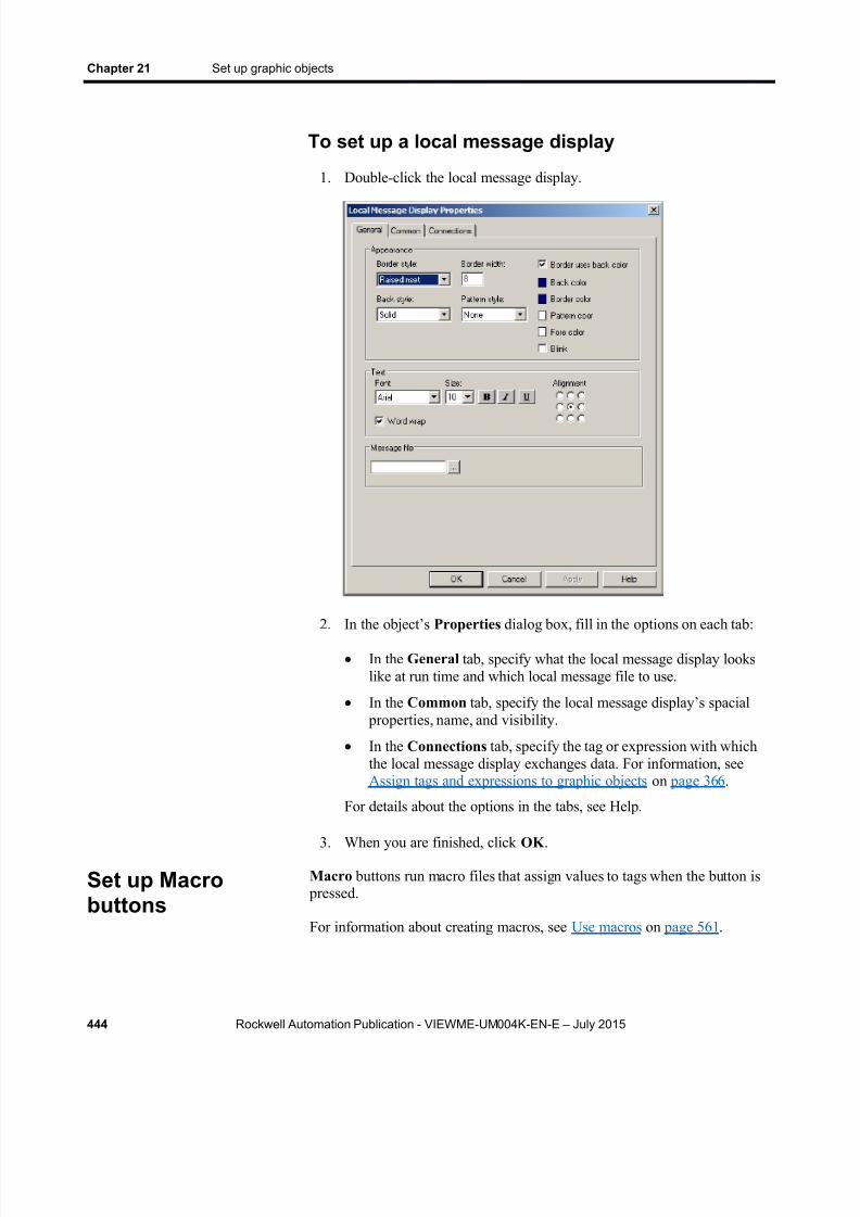
8/15/2019 Factory Talk View ME
http://slidepdf.com/reader/full/factory-talk-view-me 444/635
Chapter 21 Set up graphic objects
444 Rockwell Automation Publication - VIEWME-UM004K-EN-E – July 2015
To set up a local message display
1. Double-click the local message display.
2. In the object’s Properties dialog box, fill in the options on each tab:
In the General tab, specify what the local message display lookslike at run time and which local message file to use.
In the Common tab, specify the local message display’s spacial properties, name, and visibility.
In the Connections tab, specify the tag or expression with whichthe local message display exchanges data. For information, seeAssign tags and expressions to graphic objects on page 366 .
For details about the options in the tabs, see Help.
3. When you are finished, click OK .
Macro buttons run macro files that assign values to tags when the button is pressed.
For information about creating macros, see Use macros on page 561 .
Set up Macrobuttons

8/15/2019 Factory Talk View ME
http://slidepdf.com/reader/full/factory-talk-view-me 445/635
Set up graphic objects Chapter 21
Rockwell Automation Publication - VIEWME-UM004K-EN-E – July 2015 445
To set up a Macro button
1. Double-click the button.
2. In the button’s Properties dialog box, fill in the options on each tab:
In the General tab, specify what the button looks like at run time,and the macro to run when the button is pressed.
In the Label tab, specify what text or image to show on the button.
In the Common tab, specify the button’s spacial properties, name,and visibility.
In the Connections tab, assign tags or expressions to theconnections for the macro name.
For details about the options in the tabs, see Help.
3. When you are finished, click OK .
A time and date display shows the current time and date in a graphic display.Set up time anddate displays

8/15/2019 Factory Talk View ME
http://slidepdf.com/reader/full/factory-talk-view-me 446/635
Chapter 21 Set up graphic objects
446 Rockwell Automation Publication - VIEWME-UM004K-EN-E – July 2015
To set up a time and date display
1. Double-click the time and date display.
2. In the object’s Properties dialog box, fill in the options on each tab:
In the General tab, specify what the time and date display lookslike at run time.
In the Common tab, specify the time and date display’s spacial properties, name, and visibility.
For details about the options in the tabs, see Help.
3. When you are finished, click OK .
The operator can press the Print Alarm History button to print a report of all
the alarm messages in the alarm log file. The report can include the timealarms occurred and were acknowledged.
For information about the alarm log file, see The alarm log file on page 129 .
Set up Print AlarmHistory buttons

8/15/2019 Factory Talk View ME
http://slidepdf.com/reader/full/factory-talk-view-me 447/635
Set up graphic objects Chapter 21
Rockwell Automation Publication - VIEWME-UM004K-EN-E – July 2015 447
To set up a Print Alarm History button
1. Double-click the button.
2. In the button’s Properties dialog box, fill in the options on each tab:
In the General tab, specify what the button looks like at run time,and whether to filter the alarms to include in the report.
In the Label tab, specify what text or image to show on the button.
In the Print tab, specify what information to print on the report.
In the Common tab, specify the button’s spacial properties, name,and visibility.
For details about the options in the tabs, see Help.
3. When you are finished, click OK .
The operator can press the Print Alarm Status button to print a report of thestatus of alarms that have been defined for the application (in the AlarmSetup editor). The report can include all alarms, active alarms only, or onlyalarms that have been active since the alarm status was last reset. The reportcan include how many times each alarm was triggered, and the accumulatedtime in alarm.
Set up Print AlarmStatus buttons

8/15/2019 Factory Talk View ME
http://slidepdf.com/reader/full/factory-talk-view-me 448/635
Chapter 21 Set up graphic objects
448 Rockwell Automation Publication - VIEWME-UM004K-EN-E – July 2015
To set up a Print Alarm Status button
1. Double-click the button.
2. In the button’s Properties dialog box, fill in the options on each tab:
In the General tab, specify what the button looks like at run time,and whether to filter the alarms to include in the report.
In the Label tab, specify what text or image to show on the button.
In the Print tab, specify what information to print on the report.
In the Common tab, specify the button’s spacial properties, name,and visibility.
For details about the options in the tabs, see Help.
3. When you are finished, click OK .
The alarm list graphic object shows a list of alarms from the alarm log file. Itcan show all the alarms in the alarm log file, or any combination of active,inactive, acknowledged, and unacknowledged alarms. It can also show thealarms for specific alarm triggers.
You can assign a tag or expression to the ActiveAcknowledged,ActiveUnacknowledged, InactiveAcknowledged, orInactiveUnacknowledged connections, to allow the data source to control the
Set up alarm lists

8/15/2019 Factory Talk View ME
http://slidepdf.com/reader/full/factory-talk-view-me 449/635
Set up graphic objects Chapter 21
Rockwell Automation Publication - VIEWME-UM004K-EN-E – July 2015 449
type of alarms to show in the list. When one of the connection’s values is anon-zero value, the related type of alarm is shown in the alarm list. Theconnection value overrides the setting for the list in the Alarm ListProperties dialog box.
FactoryTalk View comes with two graphic displays, [ALARMMULTI-LINE] and [HISTORY], that contain alarm list objects. The[HISTORY] display comes in two sizes. These displays are in the graphiclibrary. You can copy the library displays into your application and use thedisplays and objects as is, customize them, or create your own.
For more information about using alarm lists, see How the alarm list graphicobject works on page 150 .
For information about the alarm log file, see The alarm log file on page 129 .
To set up an alarm list
1. Double-click the alarm list.
2. In the object’s Properties dialog box, fill in the options on each tab:

8/15/2019 Factory Talk View ME
http://slidepdf.com/reader/full/factory-talk-view-me 450/635
Chapter 21 Set up graphic objects
450 Rockwell Automation Publication - VIEWME-UM004K-EN-E – July 2015
In the General tab, specify what the button looks like at run time,whether the operator can navigate to the list using a keyboard, andhow scrolling works for the list.
In the Alarm tab, specify the columns to include in the list, thenumber of lines per alarm, and the triggers to filter by, if any.
In the Display tab, specify the types of alarms to show in the list,and the appearance of the different alarm conditions.
In the Common tab, specify the alarm list’s spacial properties,name, and visibility.
In the Connections tab, specify the tags or expressions to use tocontrol the type of alarms to show in the list. The use of theseconnections is optional.
For details about the options in the tabs, see Help.
3. When you are finished, click OK .
The alarm banner graphic object shows a single unacknowledged alarmmessage. For example, the banner could show a message that warns theoperator that the pressure in a boiler is too high.
The [ALARM] display and the [ALARM BANNER] graphic library bothcontain an alarm banner object. You can use the displays and objects as is,customize them, or create your own.
For more information about using alarm banners, see How the alarm bannergraphic object works on page 152 .
Set up alarmbanners
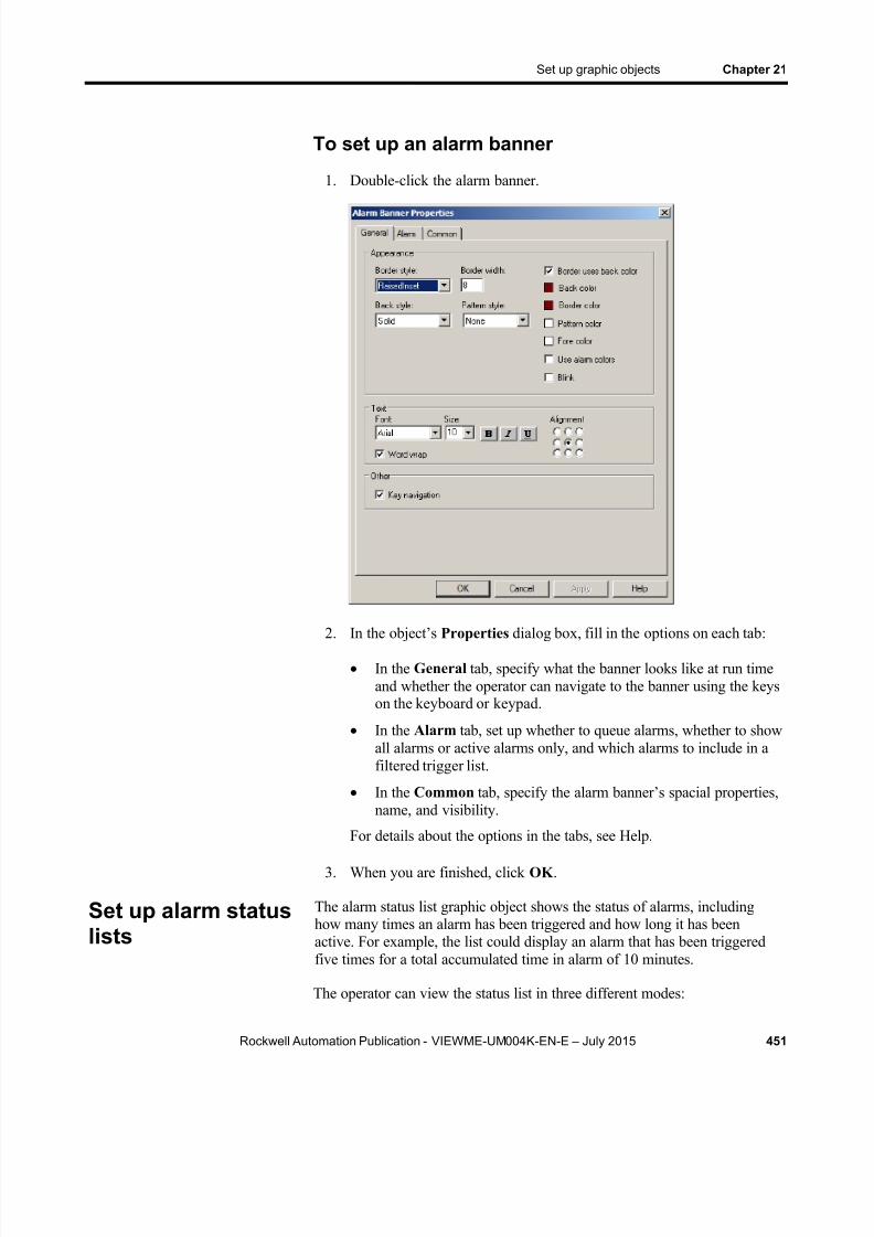
8/15/2019 Factory Talk View ME
http://slidepdf.com/reader/full/factory-talk-view-me 451/635
Set up graphic objects Chapter 21
Rockwell Automation Publication - VIEWME-UM004K-EN-E – July 2015 451
To set up an alarm banner
1. Double-click the alarm banner.
2. In the object’s Properties dialog box, fill in the options on each tab:
In the General tab, specify what the banner looks like at run timeand whether the operator can navigate to the banner using the keyson the keyboard or keypad.
In the Alarm tab, set up whether to queue alarms, whether to showall alarms or active alarms only, and which alarms to include in afiltered trigger list.
In the Common tab, specify the alarm banner’s spacial properties,name, and visibility.
For details about the options in the tabs, see Help.
3. When you are finished, click OK .
The alarm status list graphic object shows the status of alarms, includinghow many times an alarm has been triggered and how long it has beenactive. For example, the list could display an alarm that has been triggeredfive times for a total accumulated time in alarm of 10 minutes.
The operator can view the status list in three different modes:
Set up alarm statuslists

8/15/2019 Factory Talk View ME
http://slidepdf.com/reader/full/factory-talk-view-me 452/635
Chapter 21 Set up graphic objects
452 Rockwell Automation Publication - VIEWME-UM004K-EN-E – July 2015
All alarms — shows the status of all alarms that have been defined inthe Alarm Setup editor.
Active alarms — shows the status of all the alarms that are currently
active. Past alarms — shows the status of all the alarms that have been active
since the alarm status has been reset.
The operator can press the alarm status mode button to cycle through thedifferent modes.
If desired, you can set up the alarm status list to show alarms for specificalarm triggers only.
FactoryTalk View comes with a library graphic display called [STATUS]that contains an alarm status list object, alarm status mode button, and other
buttons for working with the list. You can use the display and objects as is,customize them, or create your own.
For more information about using alarm status lists, see How the alarm statuslist graphic object works on page 153 .
To set up an alarm status list
1. Double-click the alarm status list.
8/15/2019 Factory Talk View ME
http://slidepdf.com/reader/full/factory-talk-view-me 453/635
Set up graphic objects Chapter 21
Rockwell Automation Publication - VIEWME-UM004K-EN-E – July 2015 453
2. In the object’s Properties dialog box, fill in the options on each tab:
In the General tab, specify what the alarm status list looks like atrun time, whether the operator can navigate to the list using a
keyboard, and how scrolling works for the list. In the Alarm tab, specify the columns to include in the list, the
number of lines per alarm, and the triggers to filter by, if any.
In the Common tab, specify the alarm status list’s spacial properties, name, and visibility.
For details about the options in the tabs, see Help.
3. When you are finished, click OK .
The diagnostics list graphic object shows runtime information about system
activity: Information messages , such as messages about tag assignments, tag
read and write activity, and macro usage.
These are system-generated information messages. They are not thesame messages as the information messages you create and show in theinformation message display object.
Warning messages .
Error messages , such as messages about communication errors,invalid values, and unassigned connections.
Audit messages about tag writes and tag write failures.
FactoryTalk View comes with a default graphic display called[DIAGNOSTICS] that contains a diagnostics list object. You can use thedisplay and object as is, customize them, or create your own.
For more information about using diagnostics lists, see How the diagnosticslist graphic object works on page 173 .
Set up diagnosticslists

8/15/2019 Factory Talk View ME
http://slidepdf.com/reader/full/factory-talk-view-me 454/635
Chapter 21 Set up graphic objects
454 Rockwell Automation Publication - VIEWME-UM004K-EN-E – July 2015
To set up a diagnostics list
1. Double-click the diagnostics list.
2. In the object’s Properties dialog box, fill in the options on each tab:
In the General tab, specify what the list looks like at run time,whether the operator can navigate to the list using the keys on thekeyboard or keypad, and whether the cursor wraps from the bottomof the list back to the top.
In the Common tab, specify the diagnostics list’s spatial properties, name, and visibility.
For details about the options in the tabs, see Help.
3. When you are finished, click OK .
The information message display graphic object gives the operator runtimemessages about information that requires immediate attention.
FactoryTalk View comes with a default graphic display called[INFORMATION] that contains an information message display object. Youcan use the display and object as is, customize them, or create your own.
For more information about using information message displays, see Howthe information message display graphic object works on page 532 .
Set up informationmessage displays

8/15/2019 Factory Talk View ME
http://slidepdf.com/reader/full/factory-talk-view-me 455/635
Set up graphic objects Chapter 21
Rockwell Automation Publication - VIEWME-UM004K-EN-E – July 2015 455
To set up an information message display
1. Double-click the information message display.
2. In the object’s Properties dialog box, fill in the options on each tab:
In the General tab, specify what the information message displaylooks like at run time.
In the Common tab, specify the information message display’sspacial properties, name, and visibility.
For details about the options in the tabs, see Help.
3. When you are finished, click OK .

8/15/2019 Factory Talk View ME
http://slidepdf.com/reader/full/factory-talk-view-me 456/635
Chapter 21 Set up graphic objects
456 Rockwell Automation Publication - VIEWME-UM004K-EN-E – July 2015

8/15/2019 Factory Talk View ME
http://slidepdf.com/reader/full/factory-talk-view-me 457/635
Rockwell Automation Publication - VIEWME-UM004K-EN-E – July 2015 457
Chapter 22
Animate graphic objects
This chapter describes:
The types of animation and which objects support which types ofanimation
Use the Animation dialog box
Test animation
Use tag names, tag placeholders, and expressions when attachinganimation
Set the minimum and maximum values for animation that uses a rangeof motion
Use Object Smart Path to define an object’s range of motion
Set up each type of animation
Apply animation to groups
Check what kind of animation is attached to an object
Copy and paste animation
Set up animation for global objects
Animation associates graphic objects with tags so the appearance or positionof an object changes to reflect changes to the tag’s value. For example, a nobject’s color could change from yellow to orange to red as the tag’s valueincreases. Or a slider could move from left to right as a tag’s value increases.
You can use these types of animation:
Color
Fill
Height
Horizontal position
Horizontal slider
Rotation
Vertical position
Vertical slider
Types of animation

8/15/2019 Factory Talk View ME
http://slidepdf.com/reader/full/factory-talk-view-me 458/635
Chapter 22 Animate graphic objects
458 Rockwell Automation Publication - VIEWME-UM004K-EN-E – July 2015
Visibility
Width
The Objects 5 Screen Demo sample application contains many examples ofanimation. In particular, see the graphic displays called Animation I and Animation II .
Which objects can have which types of animation?
This table summarizes which types of objects support which types ofanimation. For information about the different types of graphic objects, seeTypes of graphic objects on page 331 .
These objects Support these types of animation
Drawing objects, except images,panels, and rounded rectangles
All types
Rounded rectangles All types except rotation
All other objects Visibility
You can also attach animation to groups of drawing objects. For moreinformation, see Apply animation to groups on page 471 .
You can attach as many types of animation to a drawing object (exceptimages and panels) as you like. For example, apply width, height, horizontal
position, and vertical position animation to an object to give it the appearanceof moving into or out of the display as it shrinks and grows.
To attach animation, use the Animation dialog box.
To open the Animation dialog box, do one of thefollowing
Select an object, and then on the View menu click Animation .
Select an object, and then from the Animation menu, select ananimation type. Animation types that are not supported for the selectedobject are unavailable.
Use the Animationdialog box

8/15/2019 Factory Talk View ME
http://slidepdf.com/reader/full/factory-talk-view-me 459/635
Animate graphic objects Chapter 22
Rockwell Automation Publication - VIEWME-UM004K-EN-E – July 2015 459
Right-click an object, select Animation, and then click an animationtype. Animation types that are not supported for the selected object areunavailable.

8/15/2019 Factory Talk View ME
http://slidepdf.com/reader/full/factory-talk-view-me 460/635
Chapter 22 Animate graphic objects
460 Rockwell Automation Publication - VIEWME-UM004K-EN-E – July 2015
About the Animation dialog box
The Animation dialog box is a floating dialog box, which means you cankeep it open all the time and move it around the screen. While it’s open youcan select other objects and open other dialog boxes.
For details about the parts of the Animation dialog box, see Help.
Use Object Smart Path to visually set animationBecause the Animation dialog box stays open, you can go back and forth
between the dialog box and the graphic display. This makes it easy to set therange of motion for an object because you do not have to know how many
pixels you want an object to move. Instead, you can set the range of motionvisually using the Object Smart Path feature. For details, see Use ObjectSmart Path on page 463 .
To test the animation you have set up in a graphic display, use the TestDisplay tool to switch to test mode. When you are finished testing, switch
back to edit mode to continue editing.
To switch between test and edit modes
From the View menu, select Test Display or Edit Display , or click theTest Display tool , or the Edit Display tool .
Test animation
8/15/2019 Factory Talk View ME
http://slidepdf.com/reader/full/factory-talk-view-me 461/635
Animate graphic objects Chapter 22
Rockwell Automation Publication - VIEWME-UM004K-EN-E – July 2015 461
Note: Test mode is not the same as running the display. Test modedoes not change the appearance or position of the display asset up in the Display Settings dialog box. Also, data loggingis not turned on in test mode.
When setting up animation for objects, you are linking objects to tags. Youcan specify a tag name or use tag placeholder.
You can use HMI tags or data server tags that already exist, or you can use anew tag name.
Tag placeholders allow you to create displays that can be used with differenttags.
You can use tag placeholders in:
The graphic display that opens when the application is first run.
Graphic displays that are opened using a Goto display button.
Graphic displays that are opened using a display list selector.
The graphic display that opens when the logout button is pressed.
The graphic display that opens when auto logout is used.
Graphic displays that are opened using the Remote Display Number global connection.
Use parameter files or parameter lists to specify which tags or folders tosubstitute for which placeholders. For global objects, you can specify the tagsor folders of tags using global object parameters. For more information aboutusing parameter files, parameter lists, and global object parameters, see Use
parameters and global objects on page 501 .
The tag placeholder can replace any part of a tag name, including foldernames. For example, you could create a parameter file specifying that the tag
placeholder #1=Folder1. You could assign the folder and a tag name to agraphic object’s connection: #1 \Tag1.
To create a tag placeholder In the Expression box, type the cross-hatch character followed by a
number (no space in between). For example, #1.
Many types of animation can be achieved using expressions. You can useexpressions containing tag values, constants, mathematical equations,security functions, and if-then-else logic. A tag name or tag placeholder can
be included as part of an expression, or it can stand alone as the entireexpression.
Use tag names andtag placeholders
Use expressions

8/15/2019 Factory Talk View ME
http://slidepdf.com/reader/full/factory-talk-view-me 462/635
Chapter 22 Animate graphic objects
462 Rockwell Automation Publication - VIEWME-UM004K-EN-E – July 2015
For more information about expressions, see Use expressions on page 475 .
Many types of animation require a minimum and maximum range for the tagor expression. These values determine the start and end points for a range of
motion.
For example, if you specify a minimum of 0 and a maximum of 100, theobject will not react to values outside of this range. So, even if the expressionhas a value of 200, the object does not change from its At maximum position.
When setting up animation, select one of these methods for calculating theminimum and maximum values:
Use tag’s min and max property values — select this method to usethe minimum and maximum values of the first HMI tag in theexpression. If more than one HMI tag is used in the expression, the
first HMI tag’s minimum and maximum values are used. For analog HMI tags, the values are taken from the Minimum andMaximum boxes in the Tags editor. For digital tags, the minimum is 0and the maximum is 1.
Use constant — select this method to use numeric constants. Type theminimum and maximum values in the boxes.
Read from tags — select this method to read two tags’ values todetermine the minimum and maximum values. Type the tag names inthe boxes, or click the Browse buttons to open the Tag Browser and select the tags.
If you use this method, the tags are read when the graphic displayopens. Their values at that time are used for the minimum andmaximum values. The tags are not read again after this.
To define a range of motion for an object, do one of the following:
Use the mouse to move the object in the display. This uses the ObjectSmart Path feature to visually define the range of motion.
Type values in the At minimum and At maximum boxes.
Motion can be defined in pixels, percentages, or degrees.
Animation that does not use a range of motion
Visibility and color animation do not use a range of motion, because thesetypes of animation represent a change of state, not a range of values.
Set minimum and
maximum values
Define a range ofmotion
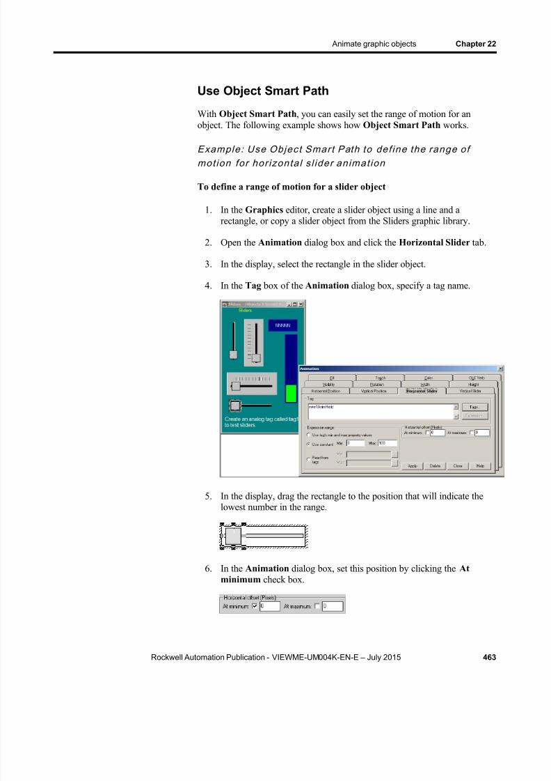
8/15/2019 Factory Talk View ME
http://slidepdf.com/reader/full/factory-talk-view-me 463/635
Animate graphic objects Chapter 22
Rockwell Automation Publication - VIEWME-UM004K-EN-E – July 2015 463
Use Object Smart Path
With Object Smart Path , you can easily set the range of motion for anobject. The following example shows how Object Smart Path works.
Example : Use Objec t Smar t Path to def ine the range ofmot ion for hor izonta l s l ider animat ion
To define a range of motion for a slider object
1. In the Graphics editor, create a slider object using a line and arectangle, or copy a slider object from the Sliders graphic library.
2. Open the Animation dialog box and click the Horizontal Slider tab.
3. In the display, select the rectangle in the slider object.
4. In the Tag box of the Animation dialog box, specify a tag name.
5. In the display, drag the rectangle to the position that will indicate thelowest number in the range.
6. In the Animation dialog box, set this position by clicking the Atminimum check box.

8/15/2019 Factory Talk View ME
http://slidepdf.com/reader/full/factory-talk-view-me 464/635
Chapter 22 Animate graphic objects
464 Rockwell Automation Publication - VIEWME-UM004K-EN-E – July 2015
7. In the display, drag the rectangle to the position that will indicate thehighest number in the range.
8. In the Animation dialog box, set this position by selecting the Atmaximum check box.
9. To save the settings, click Apply .
When you finish setting up the animation, the rectangle returns to its original position.
This section describes the different types of animation and provides tips andexamples for setting up animation.
Set up visibility animation
With visibility animation, an object becomes visible or invisible based on atag value or the result of an expression.
If an object is invisible, it is inactive.
Visibility animation is available for all objects. Visibility animation overridesan object’s Visible property.
Note: If you use a tag’s value to control visibility animation as well asin an expression to control some other aspect of animation,when you set up visibility, set the Expression true state toInvisible . If you do not do this, the object could appear brieflyin its design-time location and orientation before animatingproperly.
For more information about setting up visibility animation, see Help.
Example : Use v is ib i l ity animat ion to se t up secu r i ty for agraphic d isplay
This example shows how to use visibility animation to control what operatorscan see. In a graphic display that all users have access to, only the Adminuser can see the graphic object to which this animation is attached.
This example uses the security function CurrentUserName( ). The functionreturns the string value of the Account ID (user name) for the user who iscurrently logged in.
Set up the differenttypes of animation

8/15/2019 Factory Talk View ME
http://slidepdf.com/reader/full/factory-talk-view-me 465/635
Animate graphic objects Chapter 22
Rockwell Automation Publication - VIEWME-UM004K-EN-E – July 2015 465
The CurrentUserName( ) function is case sensitive. All user names useuppercase letters, so make sure that you use uppercase letters in yourexpression.
To specify which user can view an object in a display
1. Select the object to limit visibility to.
2. Open the Animation dialog box and click the Visibility tab.
3. In the Expression box, type this:
CurrentUserName( ) == "ADMIN"
4. For the Expression true state , select Visible .
5. Click Apply , and then click Close .
At run time, the object is visible only if the Admin user is logged in.
Set up color animation
With color animation, an object changes color based on a tag value or theresult of an expression. You can specify up to 16 color changes (A to P) forany object. Colors can be solid or blinking. For each color change, specifythe value or threshold at which the color is to change and specify the colorsto change to. At run time, when the value reaches or crosses the threshold,the color changes.
Choosing between Solid , Gradient , Original , and Shaded fill styles allowsfor more animation options for the blinking object.
Solid - Allows you to change the colors, and they will have a solidlook to them.
Gradient - Allows you to change the colors, and they will have agradient look to them. If you select Gradient as the Fill Style , the Fillcolor box changes to gradient. Click it to bring up the gradient filldialog box to configure the gradient fill.
Original - Retains the colors and the shading of the object as it wasimported. Both the line and fill color can be altered from the originalusing Blink.
Shaded - Uses a tight dot pattern to soften or give a shadedappearance. This fill style takes effect only on the group object that iscomposed of individual objects with dark to light colors, such as theSymbol Factory objects.
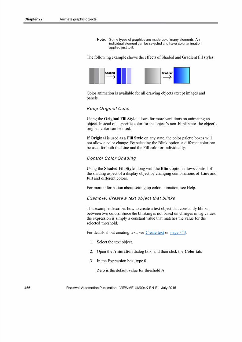
8/15/2019 Factory Talk View ME
http://slidepdf.com/reader/full/factory-talk-view-me 466/635
Chapter 22 Animate graphic objects
466 Rockwell Automation Publication - VIEWME-UM004K-EN-E – July 2015
Note: Some types of graphics are made up of many elements. Anindividual element can be selected and have color animationapplied just to it.
The following example shows the effects of Shaded and Gradient fill styles.
Color animation is available for all drawing objects except images and panels.
Keep Orig inal Color
Using the Original Fill Style allows for more variations on animating anobject. Instead of a specific color for the object’s non - blink state, the object’soriginal color can be used.
If Original is used as a Fill Style on any state, the color palette boxes willnot allow a color change. By selecting the Blink option, a different color can
be used for both the Line and the Fill color or individually.
Contro l Color Shading
Using the Shaded Fill Style along with the Blink option allows control of
the shading aspect of a display object by changing combinations of Line andFill and different colors.
For more information about setting up color animation, see Help.
Examp le: Create a text ob ject that bl inks
This example describes how to create a text object that constantly blinks between two colors. Since the blinking is not based on changes in tag values,the expression is simply a constant value that matches the value for theselected threshold.
For details about creating text, see Create text on page 343 .
1. Select the text object.
2. Open the Animation dialog box, and then click the Color tab.
3. In the Expression box, type 0.
Zero is the default value for threshold A.

8/15/2019 Factory Talk View ME
http://slidepdf.com/reader/full/factory-talk-view-me 467/635
Animate graphic objects Chapter 22
Rockwell Automation Publication - VIEWME-UM004K-EN-E – July 2015 467
4. In the list box, click threshold A. (Leave the value in the Value box as0.)
5. For the line color, click Blink . (If desired, click Blink for the fill color
too.)
6. For each color, click the color box, and then click the color to use.
7. Click Apply .
Example : Create an ob jec t tha t changes c olor as the f i l llevel ch anges
This example describes how to create a rectangle object that changes color asthe object’s fill level increases. This example uses a tag calledHopper1\FlourLevel. The tag has a range of 1 to 100. When the flour levelreaches 80, the rectangle blinks between gray and yellow to warn theoperator that the hopper is nearly full. When the flour level reaches 95, therectangle blinks between gray and red.
You could use a bar graph object (without animation) to achieve a similarresult.
1. Double-click the rectangle to open the Polygon Properties dialog box.Assign these properties to the rectangle:
In the Back style box, select Solid .
For the Fore color and Back color , select gray .
2. Click OK to close the Polygon Properties dialog box.
3. With the rectangle selected, open the Animation dialog box, and thenclick the Fill tab.
4. Attach fill animation as follows:
In the Expression box, type Hopper1\FlourLevel (this is the tagthat monitors the fill level).
For Fill Direction , click Up .
5. Click the Color tab, and then attach color animation as follows:
In the Expression box, type Hopper1\FlourLevel (the same tagthat was used in the Fill tab).
6. Set up the color for the normal state

8/15/2019 Factory Talk View ME
http://slidepdf.com/reader/full/factory-talk-view-me 468/635
Chapter 22 Animate graphic objects
468 Rockwell Automation Publication - VIEWME-UM004K-EN-E – July 2015
In the List box, select A . (In the Value box, leave the value as 0.)
For Fill Style , select Solid .
For Line and Fill , select the color box, and then select gray (thesame gray used for the rectangle).
7. Set up the color for the first warning
In the List box, select B .
In the Value box, type 80.
For Line and Fill colors, select Blink . A palette box will be shownfor the Blink color.
For the line colors, select gray for the first color and yellow for the blink color. Repeat for the fill colors.
8. Set up the color for the second warning
In the List box, select C .
In the Value box, type 95. For the Line and Fill , select Blink . A palette box will be shown for
the Blink color.
For the line colors, select gray for the first color and red for the blink color. Repeat for the fill colors.
9. Click Apply .
Set up fill animation
With fill animation, the level of fill in an object is based on a tag value (orthe result of an expression) in relation to the specified minimum and
8/15/2019 Factory Talk View ME
http://slidepdf.com/reader/full/factory-talk-view-me 469/635
Animate graphic objects Chapter 22
Rockwell Automation Publication - VIEWME-UM004K-EN-E – July 2015 469
maximum values. For example, if the value of the expression is halfway between the minimum and maximum values, the object will be half full.
Fill animation is available for all drawing objects (including group objects)
except images and panels.
If you select the Inside Only check box, fill animation does not affectobjects’ borders, line objects, or objects with transparent backgrounds.
For more information about setting up fill animation, see Help.
Set up horizontal position animation
With horizontal position animation, an object moves horizontally based on atag value (or the result of an expression) in relation to the specified minimumand maximum values. For example, if the value of the expression is halfway
between the minimum and maximum values, the object will be halfway between its minimum and maximum pixel offset.
Horizontal position animation is available for all drawing objects exceptimages and panels.
For more information about setting up horizontal position animation, seeHelp.
Set up vertical position animation
With vertical position animation, an object moves vertically based on a tagvalue (or the result of an expression) in relation to the specified minimumand maximum values. For example, if the value of the expression is halfway
between the minimum and maximum values, the object will be halfway between its minimum and maximum offset.
To move an object on the display "up", a negative offset number isrequired. The top-left corner of the display has the coordinates of 0,0.
Vertical position animation is available for all drawing objects except imagesand panels.
For more information about setting up vertical position animation, see Help.
Set up width animation
With width animation, an object’s width changes based on a tag value (or theresult of an expression) in relation to the specified minimum and maximumvalues. For example, if the value of the expression is halfway between the

8/15/2019 Factory Talk View ME
http://slidepdf.com/reader/full/factory-talk-view-me 470/635
Chapter 22 Animate graphic objects
470 Rockwell Automation Publication - VIEWME-UM004K-EN-E – July 2015
minimum and maximum values, the object’s width will be halfway b etweenits minimum and maximum percentage.
Width animation is available for all drawing objects except images and
panels.
For more information about setting up width animation, see Help.
Set up height animation
With height animation, an object’s height changes based on a tag value (orthe result of an expression) in relation to the specified minimum andmaximum values. For example, if the value of the expression is halfway
between the minimum and maximum values, the object’s height will behalfway between its minimum and maximum percentage.
Height animation is available for all drawing objects except images and panels.
For more information about setting up height animation, see Help.
Set up rotation animation
With rotation animation, an object rotates around an anchor point based on atag value (or the result of an expression) in relation to the specified minimumand maximum values. For example, if the value of the expression is halfway
between the minimum and maximum values, the object will rotate half thespecified amount.
Rotation animation is available for all drawing objects except images, panels,and rounded rectangles. If you apply rotation animation to text, the textrotates around the anchor point but remains in the upright position.
For more information about setting up rotation animation, see Help.
Set up horizontal slider animation
With horizontal slider animation, you can use a drawing object to set thevalue of a tag. To do this, define a path for the object. At run time, when theoperator moves the object horizontally (using a mouse), the pixel position ofthe object is translated into values that are written to the tag. If the tag valueis changed externally, the position of the slider changes as well.
An object can have both vertical and horizontal slider animation.

8/15/2019 Factory Talk View ME
http://slidepdf.com/reader/full/factory-talk-view-me 471/635
Animate graphic objects Chapter 22
Rockwell Automation Publication - VIEWME-UM004K-EN-E – July 2015 471
Horizontal slider animation is available for all drawing objects except imagesand panels.
For more information about setting up horizontal slider animation, see Help.
Tips
Here are some tips for creating slider objects:
The Sliders graphic library contains several slider objects you can dragand drop into your graphic displays. Attach slider animation to the
button portion of the slider object.
If you create your own slider object, it’s useful to draw an object (forexample, a line) to represent the path the slider will move along.
Set up vertical slider animation
With vertical slider animation, you can use a drawing object to set the valueof a tag. To do this, define a path for the object. At run time, when theoperator moves the object vertically (using a mouse), the pixel position of theobject is translated into values that are written to the tag. If the tag value ischanged externally, the position of the slider changes as well.
An object can have both vertical and horizontal slider animation.
To move an object on the display "up", a negative offset number isrequired. The top-left corner of the display has the coordinates of 0,0.
Vertical slider animation is available for all drawing objects except imagesand panels.
For tips about creating slider objects, see the previous section.
For more information about setting up vertical slider animation, see Help.
You can apply animation to objects and then group those objects and applyanimation to the group. When the display is running, animation is applied asfollows:
These types ofanimation Are applied like this
Color Animation attached to individual objects within thegroup overrides group animation.
Fill Animation results for both the individual objects and thegroup are applied.
Horizontal slider, verticalslider
Group animation overrides animation attached toindividual objects within the group.
Apply animation togroups

8/15/2019 Factory Talk View ME
http://slidepdf.com/reader/full/factory-talk-view-me 472/635
Chapter 22 Animate graphic objects
472 Rockwell Automation Publication - VIEWME-UM004K-EN-E – July 2015
These types ofanimation Are applied like this
Height, width, horizontalposition, vertical position,
and rotation
Animation results for individual objects and the groupare combined. For example, if an individual’s horizontal
position animation result is to offset the object by 100pixels, and the group’s result is to offset the group by200 pixels, the individual object is offset by 300 pixels.
Visibility When the group’s animation visibility is False (thegroup is not visible), then no objects in the group arevisible, regardless of the animation status of theindividual objects.When the group’s animation visibility is True (the groupis visible), the visibility of an object within the group isdetermined by the individual object animation.
Test your animation to ensure you achieve the intended results.
To apply animation to objects within groups, use the group edit feature. Fordetails, see Edit groups of objects on page 379 .
To see what type of animation has been set up for an object or group ofobjects, use the Object Explorer, the Animation menu, or the Animationdialog box.
For information about using the Object Explorer to highlight objects thathave animation attached, see Highlight objects in the Object Explorer on
page 357 .
To see what type of animation has been set up for objects within a group, usethe group edit feature or the Object Explorer. For information about using thegroup edit feature, see Edit groups of objects on page 379 .
To view the animation on an object using theAnimation menu
1. Select an object.
2. View the animation by doing one of the following:
Click the Animation menu and see which items have a check
mark. Right-click the object and then select Animation to see which
items have a check mark.
To view the animation on an object using theAnimation dialog box
1. Select an object.
Check theanimation onobjects

8/15/2019 Factory Talk View ME
http://slidepdf.com/reader/full/factory-talk-view-me 473/635
Animate graphic objects Chapter 22
Rockwell Automation Publication - VIEWME-UM004K-EN-E – July 2015 473
2. From the View menu, select Animation .
When the Animation dialog box opens, look at which tabs have checkmarks on them to see which types of animation have been set up.
You can copy or duplicate objects that have animation attached to them.When you do, the animation attached to the objects is also copied orduplicated. If you copy or duplicate a group, the copy of the group can beungrouped to individual objects, just like the original.
For information about copying and duplicating objects, see pages 20-43 on page 372 and 20-45 on page 374 .
If you have attached animation to an object, you can copy the animation and paste it onto another object. If the object has more than one type of
animation, all animation is copied and pasted. Note that you can only copyanimation to an object that supports the same type of animation.
To copy and paste animation
1. Select the object that has the animation you want to copy.
2. From the Edit menu, select Copy Animation , or right-click the objectand then select Copy Animation .
3. Select the objects to copy the animation to.
4. From the Edit menu, select Paste Animation .
To paste to a single object, you can right-click the object and thenselect Paste Animation.
Copy or duplicateobjects withanimation
Copy animation
without copyingobjects

8/15/2019 Factory Talk View ME
http://slidepdf.com/reader/full/factory-talk-view-me 474/635
Chapter 22 Animate graphic objects
474 Rockwell Automation Publication - VIEWME-UM004K-EN-E – July 2015
FactoryTalk View global objects allow you to link the appearance and behavior of a graphic object to multiple copies of that object. When theoriginal base object is updated, the changes are automatically applied to allthe copies of the object. For information about creating base objects, see Use
global objects on page 509 .
The copies of the object are called reference objects, and they have the same properties as the original base object. If desired, you can assign uniqueanimation to the reference object. For information about creating referenceobjects, see Create reference objects on page 511 .
The LinkAnimation property determines whether the reference object usesthe base object’s animation.
To set up animation for a reference object
1. Double-click the reference object to open the Property Panel .
2. Select the LinkAnimation property setting to use:
Do not link — allows you to set up separate animation for thereference object.
Link with expressions — the reference object uses the animationand tags or expressions assigned to the base object.
Link without expressions — allows you to use only the types ofanimation set up for the base object, but assign different tags orexpressions to the reference object.
3. If you selected Do not link ,or Link without expressions, set upanimation for the object using the methods described in this chapter.
For more information about setting up link properties and working withreference objects, see Set up reference objects’ link properties on page 513 .
Set up animation forglobal objects
8/15/2019 Factory Talk View ME
http://slidepdf.com/reader/full/factory-talk-view-me 475/635
Rockwell Automation Publication - VIEWME-UM004K-EN-E – July 2015 475
Chapter 23
Use expressions
This chapter describes:
The types of expression components
Use the Expression editor
Which editors use expressions
Format expressions
Use tag names and tag placeholders with expressions
Use constants
Use operators
Use math, security, and language functions
Use if-then-else logic in expressions
The evaluation order of operators
Use write expressions
Sometimes the data you gather from devices is meaningful only when you: Compare it to other values.
Combine it with other values.
Create a cause-effect relationship with other values.
Expressions allow you to create mathematical or logical combinations of datathat return more meaningful values. Depending on the components used inthe expression, the value returned can be in the form of a numeric value, atrue/false value, or a text string.
Expressions that result in floating-point values
If an expression results in a floating-point value but an integer value isrequired, the floating-point value is rounded.
For information about how values are rounded, see How values are rounded on page 98 .
About expressions
8/15/2019 Factory Talk View ME
http://slidepdf.com/reader/full/factory-talk-view-me 476/635
Chapter 23 Use expressions
476 Rockwell Automation Publication - VIEWME-UM004K-EN-E – July 2015
Expression components
Expressions can be built from:
Tag values
Tag placeholders
Constants
Arithmetic, relational, logical, and bitwise operators
Mathematical and security functions
If-then-else logic
Tags, arithmetic operators, bitwise operators, and mathematical functionssuch as SQRT (square root) return numeric values.
Relational and logical operators return true/false values. The securityfunction CurrentUserHasCode( x) also returns a true/false value.
The security function CurrentUserName( ) returns a string value. Thelanguage function CurrentLanguage( ) returns a string value.
Expressions that use if-then-else logic can return numeric values, true/falsevalues, or text strings, depending on how they are structured. These arecalled conditional expressions because the result of the expression dependson whether the If statement is true or false. When the If statement evaluatesto true, the result is defined by the Then statement. When the If statement is
false, the result is defined by the Else statement.The Objects 5 Screen Demo sample application contains many examples ofexpressions. For example, see the alarm trigger expressions in the AlarmSetup editor.
To create an expression, you can:
Type it directly in the Tag or expression column, for any connectionthat accepts expressions, or in the Expression box (for animation).
Open the Expression editor, and then create the expression in theeditor.
Use the Expression editor versus typingexpressions directly
Once you are familiar with expression syntax, you might find it quicker tocreate short expressions by typing them directly in the Tag or expression column.
Use the Expressioneditor

8/15/2019 Factory Talk View ME
http://slidepdf.com/reader/full/factory-talk-view-me 477/635
Use expressions Chapter 23
Rockwell Automation Publication - VIEWME-UM004K-EN-E – July 2015 477
The Expression editor allows you to see more text at once, which is usefulfor longer, more complicated expressions. Also, you can click buttons toenter tag names, operators, and functions, thus avoiding typing mistakes.Another advantage of using the Expression editor is that you can check
whether the syntax of the expression you have created is valid.
To crea te an express ion by typing i t d i rec t ly
Type an expression up to 16,000 characters long.
Expressions that you type directly are not checked for syntax.
To open the Express ion edi tor, do o ne of the fo l lowing
Click the Browse button in the Exprn column for a connectionthat accepts expressions.
The Browse button is not available for connections to which you canassign only tags.
In the Animation dialog box, click the Expression button.
The Expression editor has these parts:
For details about using the options in the Expression editor, see Help.
You can use expressions in these editors:
Graphics — You can define an expression to control various aspectsof a graphic object’s appearance. For more information about
Where you can useexpressions

8/15/2019 Factory Talk View ME
http://slidepdf.com/reader/full/factory-talk-view-me 478/635
Chapter 23 Use expressions
478 Rockwell Automation Publication - VIEWME-UM004K-EN-E – July 2015
assigning expressions to graphic objects, see Use expressions tomanipulate tag values on page 367 .
You can also use expressions to attach animation to graphic objects.
For more information, see Animate graphic objects on page 457 . Global Connections — You can use expressions to remotely control
when to open and print displays, as well as the date and time to show.For more information, see Set up global connections on page 111 .
Alarm Setup — When setting up alarms, you can use expressions foralarm triggers, and with some of the connections that silence andacknowledge alarms. For more information, see Set up alarms on page119 .
Information Setup — You can use expressions to determine when toshow information messages. For more information, see Useinformation messages on page 525 .
Macros — You can use expressions in macros to assign values to tags.For more information, see Use macros to assign values to tags on page561 .
You can format expressions so they are easier to read. However, do not lettag names, function names, or function arguments span more than one line.
When formatting expressions, you can use line returns and multiple spaces.
Enclose strings in quotes. The string can contain any character, and caninclude spaces.
Example: Format an expression
To format this if-then-else statement, you can align the Else with theappropriate If, so the logic is easy to understand:
if (tag1 > tag2) then 0else if (tag1 > tag3) then 2else 4
Or you can condense it to the following:
if (tag1 > tag2) then 0 else if (tag1 > tag3) then 2 else 4
A tag name can be included as part of an expression or can stand alone as theentire expression.
To supply a tag name, do one of the following:
Type a tag name.
Format expressions
Use tag names andtag placeholders
8/15/2019 Factory Talk View ME
http://slidepdf.com/reader/full/factory-talk-view-me 479/635
Use expressions Chapter 23
Rockwell Automation Publication - VIEWME-UM004K-EN-E – July 2015 479
You can type a tag name that does not exist in the tag database. Whenyou click OK, you are prompted to create the tag. You can create itnow, or write down the name and create it later.
Click the Tags button and select a tag from the Tag Browser .
Enclose tag names that contain dashes or start with a number in braces { }when you use them in an expression. This distinguishes the characters in thetag name from the characters in the expression.
You can use string tags as operands with the plus (+) arithmetic operator andwith the relational operators.
Use tag placeholders instead of tag names
The Graphics editor accepts tag placeholders instead of tag names.Placeholders allow you to use the same display with different sets of tags.
You can use tag placeholders in:
The graphic display that opens when the application is first run.
Graphic displays that are opened using a Goto display button.
Graphic displays that are opened using a display list selector.
The graphic display that is opened by a logout button.
The graphic that is opened when auto logout is used.
Graphic displays that are opened using the Remote Display Number global connection.
Use parameter files to specify which tags or folders to substitute for which placeholders. For global objects, you can specify the tags or folders of tagsusing global object parameters. For more information about using parameterfiles and global object parameters, see Use parameters and global objects on
page 501 .
The tag placeholder can replace any part of a tag name, including foldernames. For example, you could create a parameter file specifying that the tag
placeholder #1=Folder1. You could assign the folder and a tag name to agraphic object’s connection: #1 \Tag1.
To crea te a tag p laceholder in an express ion
Type the cross-hatch character followed by a number (no space in between). For example, #1.
A constant can have any of the following formats:Constants

8/15/2019 Factory Talk View ME
http://slidepdf.com/reader/full/factory-talk-view-me 480/635
Chapter 23 Use expressions
480 Rockwell Automation Publication - VIEWME-UM004K-EN-E – July 2015
Integer (123)
Floating-point (123.45)
String constant ("character string")
Arithmetic operators perform math on two or more numeric values andcalculate the result. The arithmetic operators are:
Symbol OperatorExample(For these examples, tag1 = 5 and tag2 = 7)
+ addition tag1 + tag2returns a value of 12You can also use this operator with stringoperands. See String operands on page 480 .
- subtraction tag1 - tag2returns a value of -2
* multiplication tag1 * tag2returns a value of 35
/ division tag1 / tag2returns a value of 0.7142857
MOD,% modulus (remainder) tag2 MOD tag1returns a value of 2The modulus operator is the remainder of onenumber divided by another. In the example, theremainder of 7 divided by 5 is 2; so 7 % 5 = 2Important : This operator is for integers only,not floating-point numbers.
** exponent tag1 ** tag2returns a value of 78125
Note: Be sure that any tag value you use as a divisor cannot atsome point have a value of zero. Expressions that attempt todivide a number by zero produce an error at run time.
String operandsThe + operator can be used to join string operands. For example, theexpression "hello" + "world" returns: helloworld.
You cannot join string tags to analog tags, whether they are HMI or dataserver tags.
Arithmeticoperators

8/15/2019 Factory Talk View ME
http://slidepdf.com/reader/full/factory-talk-view-me 481/635
Use expressions Chapter 23
Rockwell Automation Publication - VIEWME-UM004K-EN-E – July 2015 481
Relational operators compare two numeric or string values to provide a trueor false result. If the statement is true, a value of 1 is returned. If false, 0 isreturned.
The relational operators are:
Symbols OperatorNumericExample String Example
For the numeric examples, tag1 = 5 and tag2 = 7For the string examples, serial_no = "ST009"
EQ, == equal tag1 == tag2false
serial_no == "ST009"true
NE, <> not equal tag1 <> tag2true
serial_no <> "ST011"true
LT, < less than tag1 < tag2true serial_no < "ST011"true
GT, > greater than tag1 > tag2false
serial_no > "ST011"false
LE, <= less than or equal to tag1 <= tag2true
serial_no <= "ST011"true
GE >= greater than or equalto
tag1 >= tag2false
serial_no >= "ST011"false
How string operands are evaluated
String operands are evaluated by case and by alphabetical order. Lower caseletters are greater than upper case letters. For example, h is greater than H.Letters later in the alphabet are greater than those earlier in the alphabet. Forexample, B is greater than A.
Logical operators determine the validity of one or more statements. Thereare three logical operators: AND, OR, and NOT. The operators return anon-zero value if the expression is true, or a 0 if the expression is false.
Any statement that evaluates to a non-zero value is regarded as true. Forexample, the statement tag1 is false if the value of tag1 is 0, and true if tag1
has any other value.
The logical operators are:
Relational operators
Logical operators
8/15/2019 Factory Talk View ME
http://slidepdf.com/reader/full/factory-talk-view-me 482/635
Chapter 23 Use expressions
482 Rockwell Automation Publication - VIEWME-UM004K-EN-E – July 2015
Symbols Operator Action
Example(For these examples,tag1 = 5 and tag2 = 7)
AND, && and Returns a 1 if
the statementsto the right andleft of theoperator areboth true.
(tag1 < tag2) AND (tag1 == 5)
Both statements are true;returns a 1.
OR, || or Returns a 1 ifeither thestatement to theleft or right of theoperator is true.
(tag1 > tag2) OR (tag1 == 5)tag1 == 5 is true;returns a 1.
NOT negation Reverses thelogical value ofthe statement itoperates on.
NOT (tag1 < tag2) Although tag1 < tag2 is true,NOT reverses the logical value;returns a 0.
Note: The parentheses are essential in the above expressions. Theydetermine the evaluation order of the operators. For moreinformation, see Evaluation order of operators on page 484 .
Bitwise operators examine and manipulate individual bits within a value.
Important: These operators are for integers only, not
floating-point numbers. Do not use them with tagsor expressions that return floating-point values.
Symbol Operator Action
& And Compares two integers or tags on a bit-by-bit basis.Returns an integer with a bit set to 1 if both thecorresponding bits in the original numbers are 1.Otherwise, the resulting bit is 0.
| inclusive OR Compares two integers or tags on a bit-by-bit basis.Returns an integer with a bit set to 1 if either or bothof the corresponding bits in the original numbers are1. If both bits are 0, the resulting bit is 0.
^ exclusive OR(XOR)
Compares two integers or tags on a bit-by-bit basis.Returns an integer with a bit set to 1 if thecorresponding bits in the original numbers differ. Ifboth bits are 1 or both are 0, the resulting bit is 0.
Bitwise operators

8/15/2019 Factory Talk View ME
http://slidepdf.com/reader/full/factory-talk-view-me 483/635
Use expressions Chapter 23
Rockwell Automation Publication - VIEWME-UM004K-EN-E – July 2015 483
Symbol Operator Action
>> right shift Shifts the bits within an integer or tag to the right.Shifts the bits within the left operand by the amountspecified in the right operand. The bit on the rightdisappears.Either a 0 or a 1 is shifted in on the left, depending onwhether the left-most bit is a 0 or a 1, and whetherthe operand consists of a signed or unsigned datatype.For signed data types, if the left-most bit is 0, a 0 isshifted in. If the left-most bit is 1, a 1 is shifted in. Inother words, the sign of the number is preserved.For unsigned data types, a 0 is always shifted in.
<< left shift Shifts the bits within an integer or tag to the left.Shifts the bits within the left operand by the amountspecified in the right operand. The bit on the leftdisappears and 0 always shifts in on the right.See Use the left shift operator on page 483 .
~ complement Returns one’s complement; that is, it toggles the bitswithin an integer or tag.Reverses every bit within the number so every 1 bitbecomes a 0 and vice versa.
Use the left shift operator
If the left bit is a 1 an overflow occurs, and an error message is generated. To prevent this, use the bitwise AND operator with the left shift operator in anexpression. For example:
(dev << 1) & 65535
where dev is a tag whose value is being shifted left, and 65535 is 1111 11111111 1111 in binary form.
Examples: Bitwise operators
For these examples, tag1 = 5 (binary 0000 0000 0000 0101) andtag2 = 2 (binary 0000 0000 0000 0010)
tag1 & tag2Returns 0 (binary 0000 0000 0000 0000).
tag1 | tag2Returns 7 (binary 0000 0000 0000 0111).
tag1 ^ tag2Returns 7 (binary 0000 0000 0000 0111).
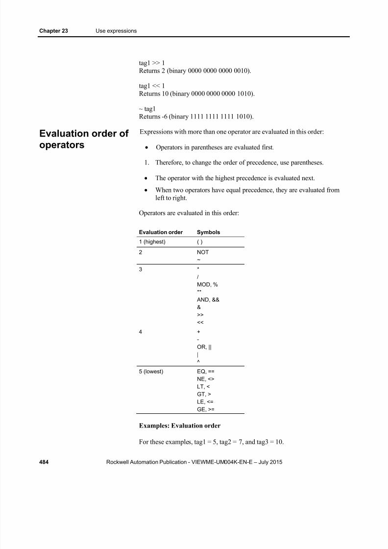
8/15/2019 Factory Talk View ME
http://slidepdf.com/reader/full/factory-talk-view-me 484/635
Chapter 23 Use expressions
484 Rockwell Automation Publication - VIEWME-UM004K-EN-E – July 2015
tag1 >> 1Returns 2 (binary 0000 0000 0000 0010).
tag1 << 1
Returns 10 (binary 0000 0000 0000 1010).
~ tag1Returns -6 (binary 1111 1111 1111 1010).
Expressions with more than one operator are evaluated in this order:
Operators in parentheses are evaluated first.
1. Therefore, to change the order of precedence, use parentheses.
The operator with the highest precedence is evaluated next.
When two operators have equal precedence, they are evaluated fromleft to right.
Operators are evaluated in this order:
Evaluation order Symbols
1 (highest) ( )
2 NOT~
3 */MOD, %**
AND, &&&>><<
4 +-OR, |||^
5 (lowest) EQ, ==NE, <>LT, <GT, >LE, <=GE, >=
Examples: Evaluation order
For these examples, tag1 = 5, tag2 = 7, and tag3 = 10.
Evaluation order ofoperators

8/15/2019 Factory Talk View ME
http://slidepdf.com/reader/full/factory-talk-view-me 485/635
Use expressions Chapter 23
Rockwell Automation Publication - VIEWME-UM004K-EN-E – July 2015 485
_____________________________
(tag1 > tag2) AND (tag1 < tag3)
is evaluated in this sequence:
1. tag1 > tag2 = 0
2. tag1 < tag3 = 1
3. 0 AND 1 = 0
The expression evaluates to 0 (false).
_____________________________
tag1 > tag2 AND tag3
is evaluated in this sequence:
1. tag2 AND tag3 = 1
2. tag1 > 1 = 1
The expression evaluates to 1 (true).
_____________________________
NOT tag1 AND tag2 > tag3 ** 2
is evaluated in this sequence:
1. NOT tag1 = 0
2. 0 AND tag2 = 0
3. tag3 ** 2 = 100
4. 0 > 100 = 0
The expression evaluates to 0 (false).
Use math functions to calculate the square root, log (natural or base 10), ortrigonometry ratios (in radians or degrees) of a tag.
This function Returns this value
SQRT (expression) The square root of the expression
LOG (expression) The natural log of the expression
LOG10 (expression) The base ten log of the expression
SIN (expression) The sine of the expression in radians
Mathematicalfunctions

8/15/2019 Factory Talk View ME
http://slidepdf.com/reader/full/factory-talk-view-me 486/635
Chapter 23 Use expressions
486 Rockwell Automation Publication - VIEWME-UM004K-EN-E – July 2015
This function Returns this value
COS (expression) The cosine of the expression in radians
TAN (expression) The tangent of the expression in radians
ARCSIN (expression) The arc sine of the expression in radians ARCCOS (expression) The arc cosine of the expression in radians
ARCTAN (expression The arc tangent of the expression in radians
SIND (expression) The sine of the expression in degrees
COSD (expression) The cosine of the expression in degrees
TAND (expression) The tangent of the expression in degrees
ARCSIND (expression) The arc sine of the expression in degrees
ARCCOSD (expression) The arc cosine of the expression in degrees
ARCTAND (expression) The arc tangent of the expression in degrees
Use security functions to control access to your application.
These functions allow you to determine a user’s identity or security rights inorder to limit access to the application based on these criteria.
This function Returns this value
CurrentUserName( ) A string containing the name of the current user.This function is case sensitive. All RSView 3.20 andearlier user names use uppercase letters.
CurrentUserHasCode(Security Code Letters )
True (1) if any of the specified security codes havebeen assigned to the user; false (0) if not.If checking multiple security codes, do not type a spacebetween the security code letters.For example: CurrentUserHasCode(ABP) returns thevalue 1 if the user has been assigned one or more ofthe specified codes.
CurrentUserHasGroup( "Group Name" )
True (1) if the current user is assigned to the specifiedgroup configured in FactoryTalk Directory; false (0) ifnot.This function is only supported in 8.0 and later versionsof FactoryTalk ME applications.The group name must be enclosed with double quotes.For example, CurrentUserHasGroup("Group A") returnsthe value 1 if the user has been assigned to Group A.
For more information about setting up security for your application, see Setup security on page 175 .
For an example of using the CurrentUserHasCode( x) function, see To assignvisibility animation to the shutdown button on page 190 .
For examples of using the CurrentUserName( ) function, see To assignvisibility animation to the Goto display button on page 189 .
Security functions
8/15/2019 Factory Talk View ME
http://slidepdf.com/reader/full/factory-talk-view-me 487/635
Use expressions Chapter 23
Rockwell Automation Publication - VIEWME-UM004K-EN-E – July 2015 487
The language function shows you which language your application iscurrently using.
You can show the current language in a string display, or use it in
expressions to generate language-specific messages for your users.
This function Returns this value
CurrentLanguage( ) RFC1766 name of the current runtime language.
The RFC1766 name is a standard way of representing a language using theformat: languagecode -Country/RegionCode
where languagecode is a lowercase two-letter code and Country / RegionCode is an uppercase two-letter code.
For example, U.S. English is en-US.
For more information about setting up languages for your application, see Setup language switching on page 197 . For a list of RFC1766 names, seeRFC1766 names on page 601 .
Language switching alarm, information, and localmessages in FactoryTalk View ME Station 4.00
FactoryTalk View 5.00 and later provides direct support for switchingmessage languages at run time.
For applications that will run in FactoryTalk View ME Station version 4.00,use the CurrentLanguage( ) expression function to specify message offsets inthe information message file. In the file, divide your messages into sectionsfor each language. To do this, set up trigger value offsets for series ofmessages in the Alarm Setup editor, information message files, and localmessage files.
Export the text strings in the Alarm Setup editor and message files fortranslation. Then paste the translated strings into the editor and originalmessage files, and assign each string the correct trigger value. Forinformation about exporting text for translation, see Set up languageswitching on page 197 .
Example: Set up information messages in multiple languages
This example shows how to generate English, French, or Germaninformation messages at run time in an FactoryTalk View ME Station 4.00application, depending on which language the application is using.
Language function

8/15/2019 Factory Talk View ME
http://slidepdf.com/reader/full/factory-talk-view-me 488/635
Chapter 23 Use expressions
488 Rockwell Automation Publication - VIEWME-UM004K-EN-E – July 2015
1. Create a tag called Information_messages that will generate triggervalues of 11 to 20 for different conditions that require informationmessages.
2. Create an information message file.
3. Create English messages for trigger values 11 to 20.
Tip: Messages are sorted alphanumerically in the Excelspreadsheet or Unicode text file created for translation.Therefore, numbers 2 through 9 would appear after 10,11, 12, and so on. To keep your messages in order in thetranslation file, begin the first series of numbers at 11.
4. Create French messages for trigger values 21 to 30.
5. Create German messages for trigger values 31 to 40.
6. Assign this expression to the Value connection in the InformationSetup editor:
If CurrentLanguage( )="en-US" thenInformation_messages
Else If CurrentLanguage( )="fr-FR" thenInformation_messages + 10
Else Information_messages + 20
If-then-else expressions carry out an action conditionally or branch actions
depending on the statements in the expression. The if-then-else statementsenable the expression to perform different actions in different situations andto repeat activities until a condition changes.
To build conditional expressions, use the relational operators and the logicaloperators for the statement and values.
The if-then-else structure is:
if statement then value1 else value2
If the statement is true then the expression returns value1; if the statement is
false then the expression returns value2. If the result of the statement is anon-zero value, the statement is true (and returns value1); if the result is 0,the statement is false (and returns value2).
If-then-else
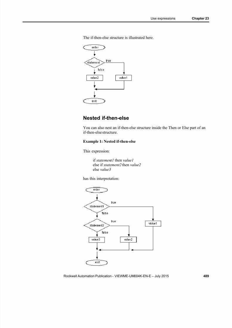
8/15/2019 Factory Talk View ME
http://slidepdf.com/reader/full/factory-talk-view-me 489/635
Use expressions Chapter 23
Rockwell Automation Publication - VIEWME-UM004K-EN-E – July 2015 489
The if-then-else structure is illustrated here.
Nested if-then-else
You can also nest an if-then-else structure inside the Then or Else part of anif-then-else structure.
Example 1: Nested if-then-else
This expression:
if statement1 then value1 else if statement2 then value2 else value3
has this interpretation:
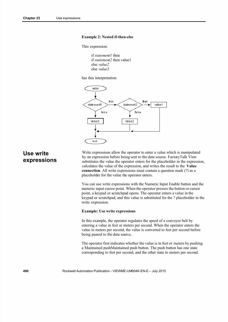
8/15/2019 Factory Talk View ME
http://slidepdf.com/reader/full/factory-talk-view-me 490/635
Chapter 23 Use expressions
490 Rockwell Automation Publication - VIEWME-UM004K-EN-E – July 2015
Example 2: Nested if-then-else
This expression:
if statement1 thenif statement2 then value1else value2 else value3
has this interpretation:
Write expressions allow the operator to enter a value which is manipulated by an expression before being sent to the data source. FactoryTalk Viewsubstitutes the value the operator enters for the placeholder in the expression,calculates the value of the expression, and writes the result to the Valueconnection . All write expressions must contain a question mark (?) as a
placeholder for the value the operator enters.
You can use write expressions with the Numeric Input Enable button and thenumeric input cursor point. When the operator presses the button or cursor
point, a keypad or scratchpad opens. The operator enters a value in thekeypad or scratchpad, and this value is substituted for the ? placeholder in thewrite expression.
Example: Use write expressions
In this example, the operator regulates the speed of a conveyor belt byentering a value in feet or meters per second. When the operator enters thevalue in meters per second, the value is converted to feet per second before
being passed to the data source.
The operator first indicates whether the value is in feet or meters by pushinga Maintained pushMaintained push button. The push button has one statecorresponding to feet per second, and the other state to meters per second.
Use writeexpressions

8/15/2019 Factory Talk View ME
http://slidepdf.com/reader/full/factory-talk-view-me 491/635
Use expressions Chapter 23
Rockwell Automation Publication - VIEWME-UM004K-EN-E – July 2015 491
Then the operator presses the Numeric Input Enable button and enters thevalue for the conveyor speed in a numeric pop-up keypad. The ? character inthe write expression is the placeholder for the value the operator enters.
To set up the Maintained push button
1. In the Maintained Push Button Properties dialog box, in the Statestab, set up these states:
State 0 — Value: 0, Caption: Feet/S
State 1 — Value: 1, Caption: Meters/S
2. In the Connections tab, assign a digital tag called Feet_or_meters tothe Value connection (either an HMI tag or a data server tag).
To set up the Numeric Input Enable button
1. In the Numeric Input Enable Properties dialog box, in the Label tab,type the caption Enter conveyor speed .
2. In the Connections tab, assign a tag called Conveyor_speed to theValue connection.
3. Assign this expression to the Optional Exp connection:
if Feet_or_meters == 0 then?else? * 3.281
FactoryTalk View writes the result of the expression to the Conveyor_speedtag at the data source.

8/15/2019 Factory Talk View ME
http://slidepdf.com/reader/full/factory-talk-view-me 492/635
Chapter 23 Use expressions
492 Rockwell Automation Publication - VIEWME-UM004K-EN-E – July 2015

8/15/2019 Factory Talk View ME
http://slidepdf.com/reader/full/factory-talk-view-me 493/635
Rockwell Automation Publication - VIEWME-UM004K-EN-E – July 2015 493
Chapter 24
Use embedded variables
This chapter describes:
The types of embedded variables
Where you can create embedded variables
Create embedded variables
Embedded variable syntax
How embedded variables are updated at run time
How embedded variables are shown at run time
Embedded variables allow you to show values that change dynamically atrun time. You can use embedded variables in the text captions on graphicobjects, in the title bar of On Top displays, and in message text. You can usemultiple embedded variables in the same caption or message.
For example, you could embed a tag value and the time variable in a localmessage. At run time when the local message is shown, it is updated toreflect the tag’s current value as the value changes. The time is also updated
as the time changes.
You can also use literal strings and constants in embedded variables, or acombination of both variable and literal strings and numbers.
Embedded variables can consist of:
Numeric (analog or digital) tags, including both HMI and data servertags
Literal numbers (constants)
String tags, including both HMI and data server tags
Literal strings (static text)
Tag placeholders. For information about tag placeholders, see Use tag placeholders on page 501 .
The time
The date
About embeddedvariables

8/15/2019 Factory Talk View ME
http://slidepdf.com/reader/full/factory-talk-view-me 494/635
Chapter 24 Use embedded variables
494 Rockwell Automation Publication - VIEWME-UM004K-EN-E – July 2015
You can create embedded variables in these editors:
Graphics — Use this editor to insert embedded variables in thecaptions for graphic objects. For graphic objects with multiple states,
you can insert different embedded variables in each state’s caption. You can also use embedded variables in the title bar for On Topdisplays.
For information about specific graphic objects, see Set up graphicobjects on page 389 . For information about On Top displays, see OnTop displays on page 311 .
Local Messages — Use this editor to insert embedded variables inlocal messages.
For more information about local messages, see Use local messages on
page 325 . Information Messages — Use this editor to insert embedded variables
in information messages.
For more information about information messages, see Useinformation messages on page 525 .
Alarm Setup — Use this editor to insert embedded variables in alarmmessages.
For more information about alarms, see Set up alarms on page 119 .
To create an embedded variable in a graphicobject’s caption
1. Open the graphic object’s Properties dialog box.
2. Click the tab containing the Caption box.
The Caption box is on the Label tab or the States tab, depending onthe type of object.
For text objects, use the Text box on the General tab.
3. Click Insert Variable .
4. Click the type of variable to insert.
5. Fill in the options in the dialog box that opens. For details about theoptions, see Help.
Where you cancreate embeddedvariables
Create embeddedvariables

8/15/2019 Factory Talk View ME
http://slidepdf.com/reader/full/factory-talk-view-me 495/635
Use embedded variables Chapter 24
Rockwell Automation Publication - VIEWME-UM004K-EN-E – July 2015 495
To create an embedded variable in an On Topdisplay’s title bar
1. Open the Display Settings dialog box.
2. Select the Title Bar check box if it is not already selected.
3. Click Insert Variable .
4. Click the type of variable to insert.
5. Fill in the options in the dialog box that opens. For details about theoptions, see Help.
To create an embedded variable in a message1. In the Message column of the Local Messages , Information
Messages , or Alarm Setup editor, right click and then click EditString .
2. Click Insert Variable .
3. Click the type of variable to insert.
4. Fill in the options in the dialog box that opens. For details about theoptions, see Help.
Embedded variables are case sensitive, and must use specific syntax to work.Otherwise, the embedded variable is treated as a piece of text. Therefore, wedo not recommend creating and editing embedded variables manually.Instead, use the Insert Variable and Edit Variable dialog boxes.
Numeric embedded variable syntax
Use numeric embedded variables to insert analog or digital tag values intocaptions, title bars, and messages. You can use both HMI and data servertags.
You can also insert "literal" numbers to show a constant or to specify a tag placeholder in the caption or message.
Embedded variablesyntax
8/15/2019 Factory Talk View ME
http://slidepdf.com/reader/full/factory-talk-view-me 496/635
Chapter 24 Use embedded variables
496 Rockwell Automation Publication - VIEWME-UM004K-EN-E – July 2015
Numeric embedded variables use this syntax:
/*LN:# Tag_name Fill_character DP:#*/
where
L (optional) indicates it is a literal (constant) number. This symbol prevents a tag read. If you type a tag placeholder for the Tag_name , thevalue of the placeholder is substituted from the parameter file or globalobject parameter definition.
N indicates it’s a numeric embedded variable.
# indicates the number of digits.
Tag_name is the tag to show; you can also type a literal number or tag placeholder here.
Fill_character is the fill character to use: NOFILL, ZEROFILL, orSPACEFILL.
# indicates the number of decimal places.
Examples: Numeric embedded variable syntax
To show the current value of a tag called Oven_temp, with 3 digits, nodecimal places, and no fill character, type this:
/*N:3 Oven_temp NOFILL DP:0*/
To show the constant 48, with 3 decimal places and 2 zeroes to the left of thenumber (for a total length of 8 digits including the decimal), type this:
/*LN:8 48 ZEROFILL DP:3*/
At run time the numeric embedded variable would look like this: 0048.000.
String embedded variable syntax
Use string embedded variables to insert string tag values into captions, title bars, and messages.
You can also insert "literal" strings of static text. For example, you can type aword or phrase, a tag placeholder, or a number. To control how constantnumbers are shown, use a literal numeric variable rather than a stringvariable.
String embedded variables use this syntax:
/*LS:-# Tag_name SHOWSTAR*/
where
8/15/2019 Factory Talk View ME
http://slidepdf.com/reader/full/factory-talk-view-me 497/635
Use embedded variables Chapter 24
Rockwell Automation Publication - VIEWME-UM004K-EN-E – July 2015 497
L (optional) indicates it is a literal (static) string. This symbol preventsa tag read. If you type a tag placeholder for the Tag_name , the value ofthe placeholder is substituted from the parameter file or global object
parameter definition. The value cannot contain spaces.
S indicates it’s a string embedded variable.
- (optional). A minus sign (-) before the # indicates that if the string islonger than the fixed number of characters, the right-most characterswill be shown.
# indicates the number of characters if you select a fixed number ofcharacters; type 0 if you don’t want to use a fixed number.
Tag_name is the tag to show; you can also type a literal string or tag placeholder here. The string cannot contain spaces.
SHOWSTAR (optional) specifies that if the string is longer than the
fixed number of characters, an asterisk (*) will be shown to indicatethe string is truncated. If you use the minus sign (-), the asterisk will beshown as the first character at the left end of the string. Otherwise, theasterisk will be shown as the last character at the right end of the string.
Examples: String embedded variable syntax
To show the current value of a string tag called Blower_status, with a fixedlength of 20 characters, you would type this:
/*S:20 Blower_status*/
To show the literal string Oven temperature, type this:/*LS:20 "Oven temperature"*/
To show the literal string 36.5, type this:
/*LS:3 36.5*/
To assign the tag placeholder #1, without a fixed string length, type this:
/*S:0 #1*/
To show the value of the string tag Conveyor_message, with a fixed lengthof 40, showing the right-most characters, with an asterisk to indicate if themessage is truncated, type this:
/*S:-40 Conveyor_message SHOWSTAR*/
Time and date embedded variable syntax
Use time and date embedded variables to insert the current time or date intocaptions, title bars, and messages
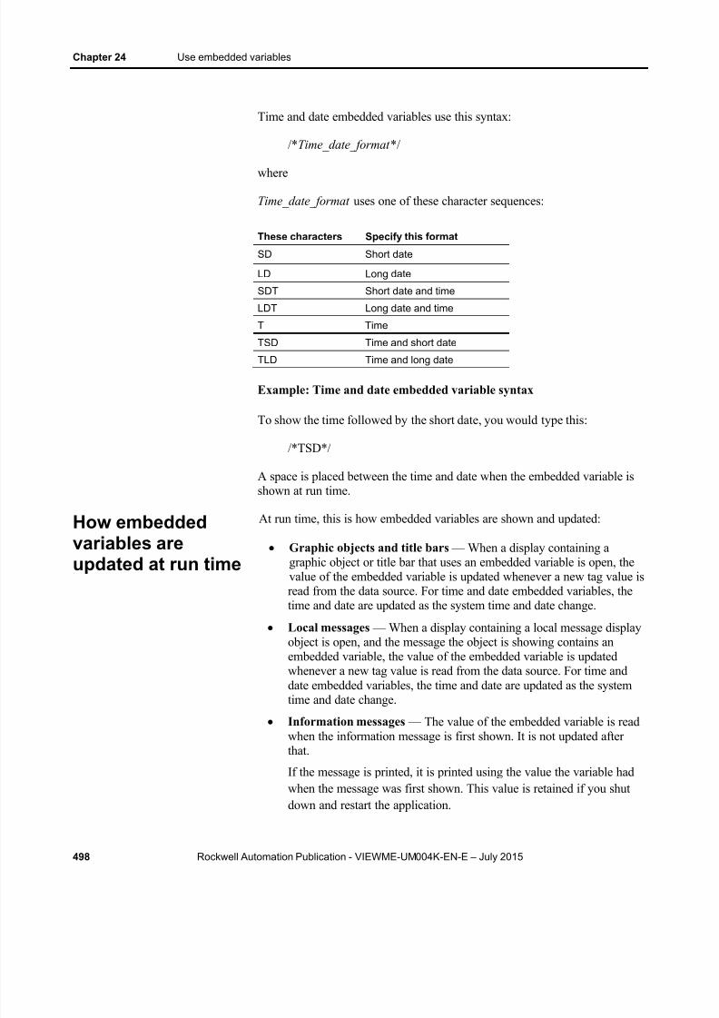
8/15/2019 Factory Talk View ME
http://slidepdf.com/reader/full/factory-talk-view-me 498/635
Chapter 24 Use embedded variables
498 Rockwell Automation Publication - VIEWME-UM004K-EN-E – July 2015
Time and date embedded variables use this syntax:
/*Time_date_format */
where
Time_date_format uses one of these character sequences:
These characters Specify this format
SD Short date
LD Long date
SDT Short date and time
LDT Long date and time
T Time
TSD Time and short dateTLD Time and long date
Example: Time and date embedded variable syntax
To show the time followed by the short date, you would type this:
/*TSD*/
A space is placed between the time and date when the embedded variable isshown at run time.
At run time, this is how embedded variables are shown and updated:
Graphic objects and title bars — When a display containing agraphic object or title bar that uses an embedded variable is open, thevalue of the embedded variable is updated whenever a new tag value isread from the data source. For time and date embedded variables, thetime and date are updated as the system time and date change.
Local messages — When a display containing a local message displayobject is open, and the message the object is showing contains anembedded variable, the value of the embedded variable is updatedwhenever a new tag value is read from the data source. For time anddate embedded variables, the time and date are updated as the systemtime and date change.
Information messages — The value of the embedded variable is readwhen the information message is first shown. It is not updated afterthat.
If the message is printed, it is printed using the value the variable hadwhen the message was first shown. This value is retained if you shutdown and restart the application.
How embeddedvariables areupdated at run time

8/15/2019 Factory Talk View ME
http://slidepdf.com/reader/full/factory-talk-view-me 499/635
Use embedded variables Chapter 24
Rockwell Automation Publication - VIEWME-UM004K-EN-E – July 2015 499
Alarm messages — The value of the embedded variable is read whenthe alarm occurs, and is shown in the message associated with thealarm. It is not updated after that.
If the message is printed, it is printed using the value the variable hadwhen the alarm first occurred. This value is retained if you shut downand restart the application.
If there is no valid data available for the embedded variable, the variable isreplaced with question marks (?). This could occur when a display firstopens and the data has not arrived yet, or when there is a problem that
prevents communication with the data source.
If a string or numeric embedded variable has been set up but no tag has beenassigned, the embedded variable is replaced with asterisks (*).
Numeric embedded variables
The value shown for a numeric embedded variable depends on whether thetag value is a floating-point number or an integer. Integer values are shownas is. Floating-point values are rounded to fit the specified number of digitsfor the variable.
For example, if the variable is set up to show 6 digits, 1234.56 is rounded to1234.6. 1234.44 is rounded to 1234.4. The decimal counts as one of thedigits.
For more information about how values are rounded, see How values arerounded on page 98 .
If the tag value, including the decimal point and minus sign, contains moredigits than specified for the variable, the numeric variable is replaced withasterisks.
For example, if the variable is set up to show 6 digits, and the tag value is-123456, the variable will be replaced with asterisks.
Literal numbers are shown using the same rules as numeric tag values.
Number formats
The numeric variable uses the number format of the current applicationlanguage. For example, if the application language uses a comma for thedecimal symbol, the numeric variable uses a comma for the decimal symbol.
For information about using multiple languages, see Set up languageswitching on page 197 .
How embeddedvariables are shownat run time
8/15/2019 Factory Talk View ME
http://slidepdf.com/reader/full/factory-talk-view-me 500/635
Chapter 24 Use embedded variables
500 Rockwell Automation Publication - VIEWME-UM004K-EN-E – July 2015
String embedded variables
For string embedded variables that do not use a fixed number of characters,the entire string tag value is shown, unless a null character is read. Nothingafter a null character is shown.
If a fixed number of characters is used, the variable shows the value of thetag up to the number of characters specified, unless a null character isencountered before the specified length. Nothing is shown after a nullcharacter. If necessary, spaces are used to make up the required number ofcharacters.
Null characters have a hex value of 0. The null character indicates the end ofstring input. It does not add to the actual string length.
If the string is longer than the specified number of characters, it is truncated
to fit the number of characters. If the SHOWSTAR option is used, an asterisk(*) replaces the first or last character shown. If the embedded variable is setup to show right-most characters, excess characters are truncated at the leftend of the string and the asterisk (if used) appears at the left. Otherwise, theright-most characters are truncated and the asterisk (if used) appears at theright.
Literal strings are shown using the same rules as string tag values.
Time and date embedded variables
For embedded variables that show both the time and the date, a space is placed between the time and date when the embedded variable is shown atrun time.
Time and date formats
Time and date embedded variables use the time and date formats for thecurrent application language. For example, if you specify the short dateformat, at run time the display uses the short date format that the applicationlanguage uses.
For information about using multiple languages, see Set up languageswitching on page 197 .

8/15/2019 Factory Talk View ME
http://slidepdf.com/reader/full/factory-talk-view-me 501/635
Rockwell Automation Publication - VIEWME-UM004K-EN-E – July 2015 501
Chapter 25
Use parameters and global objects
This chapter describes:
Use tag placeholders and parameter files or lists
Create tag placeholders
Create parameter files and parameter lists
Use global objects
Create global object displays and base objects
Create, set up, and delete reference objects
Use global object parameters
Adding controller instruction faceplates that connect to Logix5000 processors
The topics in this chapter describe features of FactoryTalk View Studio thatcan help you set up your applications more quickly by reusing similar groupsof objects and graphic displays.
Tag placeholders, parameter lists, and parameter files allow you to usethe same graphic display with different sets of tags.
Global objects allow you to use multiple instances of the same graphicobject and make changes to all of the objects at once.
Global object parameters allow you to assign different sets of tags todifferent copies of the object without breaking the link to the baseobject, thus preserving the ability to update all copies of the object atonce.
Controller instruction faceplates provide pre-configured graphicdisplays that interact with the instructions in Logix5000 processors.
Use a tag placeholder to mark where you want to insert a tag name or some part of a tag name at run time. A tag placeholder is a crosshatch character (#)followed by a number from 1 to 500.
FactoryTalk View Machine Edition uses three methods for replacing a tag placeholder with a tag name:
Parameter files
Parameter lists
Use tagplaceholders

8/15/2019 Factory Talk View ME
http://slidepdf.com/reader/full/factory-talk-view-me 502/635
Chapter 25 Use parameters and global objects
502 Rockwell Automation Publication - VIEWME-UM004K-EN-E – July 2015
Global object parameters
To use the same graphic display with different sets of tags, use tag placeholders with parameter files or parameter lists. Using tag placeholders
can be quicker than duplicating a display and setting up the objects in it touse a different set of tags, especially when the display uses a lot of tags.Using parameter files or parameter lists also reduces the size of the runtimeapplication file.
You can use tag placeholders wherever you would normally assign a tag toan object, including in expressions and embedded variables. You can also usetag placeholders in the expressions you create to animate objects.
Tag placeholders can provide a way to use one graphic display to represent anumber of similar operations. For example, suppose you are creating displaysfor a plant that cans corn and peas. The machinery used in both processes is
identical. Instead of creating two displays and specifying corn-related tags inone display and pea-related tags in another, you can create one display andnot specify any tag names. Where a tag name is required, type a tag
placeholder.
Use parameter files or parameter lists to specify which tags to substitute forwhich placeholders when a display opens at run time. For information aboutusing parameter files, see Create parameter files on page 504 . Forinformation about using parameter lists, see Create parameter lists on page507 .
You can also use tag placeholders with global objects. You can assign tag
placeholders to the connections for base objects, and to connections forreference objects with the LinkConnections property set to False . For moreinformation about global objects, see Use global objects on page 509 .
You can use tag placeholders in:
The graphic display that opens when the application is first run.Specify the graphic display to open, and the parameter file or
parameter list to use with it, in the Startup editor.
Graphic displays that are opened using Goto display buttons. Specifythe graphic display to open, and the parameter file or parameter list touse with it, when you set up the button.
Graphic displays that are opened using display list selectors. Specifythe graphic displays to open, and the parameter files or parameter liststo use with them, when you set up the display list selector.
The graphic display that opens when a logout button is pressed.
The graphic display specified in the Project Settings Runtime tabwhen auto logout is enabled.
Displays specified in the Display tab of the Global Connections editor.

8/15/2019 Factory Talk View ME
http://slidepdf.com/reader/full/factory-talk-view-me 503/635
Use parameters and global objects Chapter 25
Rockwell Automation Publication - VIEWME-UM004K-EN-E – July 2015 503
Steps for using tag placeholders
Follow these steps to use tag placeholders with parameter files or parameterlists:
1. In the Graphics editor, create graphic objects and assign tag placeholders to the objects.
2. If you are using parameter files, create parameter files in theParameters editor for each set of tags that the display will use. In the
parameter files, specify which tags to substitute for which placeholders.
3. In the Graphics editor, create Goto display buttons, logout buttons, ordisplay list selectors for opening the display containing tag
placeholders. Specify the appropriate parameter files in the graphic
object’s dialog box.
To use parameter lists, specify the tags for the lists in the dialog box.
For information about setting up Goto display buttons, see Set up Gotodisplay buttons on page 425 .
For information about setting up display list selectors, see Set updisplay list selectors on page 427 .
For information about setting up buttons, see To set up a button on page 405 .
4. If the startup display uses tag placeholders, in the Startup editor,specify the parameter file to use with the startup display. To use a
parameter list, specify the tags for the list in the Startup editor.
For information about the Startup editor, see Create runtimeapplications on page 221 .
5. If auto logout is enabled, you have the option of opening a display onlogout. Specify the appropriate parameter file in the Runtime tab of theProject Settings dialog box. To use a parameter list, specify the tagsfor the list in the Project Settings dialog box.
For information about the Project Settings editor, see Help.
6. If the displays that will be changed remotely by global connections use parameters, specify the parameter file or parameter list in the Display tab of the Global Connections editor.
For information on global connections, see Set up global connections on page 111 .

8/15/2019 Factory Talk View ME
http://slidepdf.com/reader/full/factory-talk-view-me 504/635
Chapter 25 Use parameters and global objects
504 Rockwell Automation Publication - VIEWME-UM004K-EN-E – July 2015
Create tag placeho lders
A tag placeholder is the crosshatch character (#) followed by a number.
The tag placeholder can replace any part of a tag name, including foldernames. For example, you could create a parameter file specifying that the tag
placeholder #1=Folder1. You could assign the folder and a tag name to agraphic object’s connection: #1 \Tag1.
You can create tag placeholders in:
The Connections tab of an object’s Properties dialog box.
The Connections tab of the Property Panel .
The Expression box in the Animation dialog box.
A global object’s Parameter Definitions dialog box. Anywhere that you can insert an embedded variable. For information
about embedded variables, see Use embedded variables on page 493 .
To create a tag placeho lder
Type the cross-hatch character followed by a number from 1 to 500 (nospace in between). For example, #1.
Create parameter files
The parameter file specifies which tags to substitute for the placeholders inthe display, by assigning one tag to each unique placeholder in the display.Create a parameter file for each set of tags that you want to use with the samegraphic display.
At run time, the tag values that are shown depend on which parameter file isused when the display opens. When you open the display, the tags specifiedin the parameter file replace the tag placeholders.
Parameters can replace any portion of a tag address. For example, you canuse parameters to replace folder names.
Parameter files can list up to 500 tag placeholders. Use them when a largenumber of tag placeholders are needed for a display. The text format of a
parameter file allows you to see and edit the placeholders easily. Whencopying displays from one application to another, the related parameter filesmust also be copied.
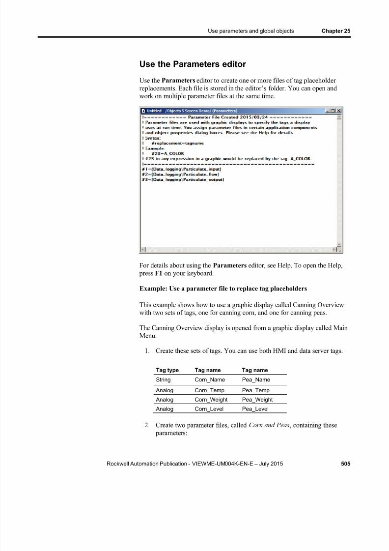
8/15/2019 Factory Talk View ME
http://slidepdf.com/reader/full/factory-talk-view-me 505/635
Use parameters and global objects Chapter 25
Rockwell Automation Publication - VIEWME-UM004K-EN-E – July 2015 505
Use the Parameters editor
Use the Parameters editor to create one or more files of tag placeholderreplacements. Each file is stored in the editor’s folder. You can open andwork on multiple parameter files at the same time.
For details about using the Parameters editor, see Help. To open the Help, press F1 on your keyboard.
Example: Use a parameter file to replace tag placeholders
This example shows how to use a graphic display called Canning Overviewwith two sets of tags, one for canning corn, and one for canning peas.
The Canning Overview display is opened from a graphic display called MainMenu.
1. Create these sets of tags. You can use both HMI and data server tags.
Tag type Tag name Tag name
String Corn_Name Pea_Name
Analog Corn_Temp Pea_Temp
Analog Corn_Weight Pea_Weight
Analog Corn_Level Pea_Level
2. Create two parameter files, called Corn and Peas , containing these parameters:
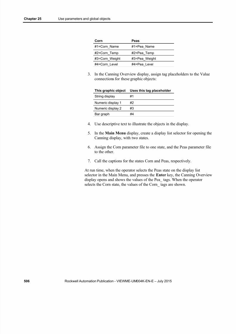
8/15/2019 Factory Talk View ME
http://slidepdf.com/reader/full/factory-talk-view-me 506/635
Chapter 25 Use parameters and global objects
506 Rockwell Automation Publication - VIEWME-UM004K-EN-E – July 2015
Corn Peas
#1=Corn_Name #1=Pea_Name
#2=Corn_Temp #2=Pea_Temp
#3=Corn_Weight #3=Pea_Weight
#4=Corn_Level #4=Pea_Level
3. In the Canning Overview display, assign tag placeholders to the Valueconnections for these graphic objects:
This graphic object Uses this tag placeholder
String display #1
Numeric display 1 #2
Numeric display 2 #3
Bar graph #4
4. Use descriptive text to illustrate the objects in the display.
5. In the Main Menu display, create a display list selector for opening theCanning display, with two states.
6. Assign the Corn parameter file to one state, and the Peas parameter fileto the other.
7. Call the captions for the states Corn and Peas, respectively.
At run time, when the operator selects the Peas state on the display listselector in the Main Menu, and presses the Enter key, the Canning Overviewdisplay opens and shows the values of the Pea_ tags. When the operatorselects the Corn state, the values of the Corn_ tags are shown.
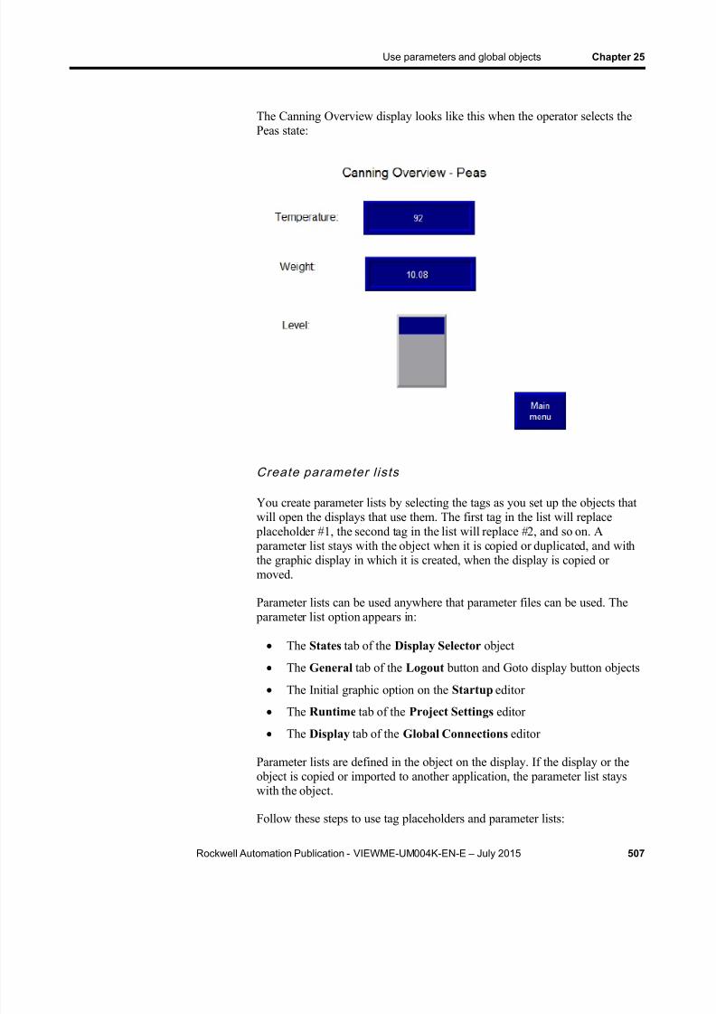
8/15/2019 Factory Talk View ME
http://slidepdf.com/reader/full/factory-talk-view-me 507/635
Use parameters and global objects Chapter 25
Rockwell Automation Publication - VIEWME-UM004K-EN-E – July 2015 507
The Canning Overview display looks like this when the operator selects thePeas state:
Create parameter l is ts
You create parameter lists by selecting the tags as you set up the objects that
will open the displays that use them. The first tag in the list will replace placeholder #1, the second tag in the list will replace #2, and so on. A parameter list stays with the object when it is copied or duplicated, and withthe graphic display in which it is created, when the display is copied ormoved.
Parameter lists can be used anywhere that parameter files can be used. The parameter list option appears in:
The States tab of the Display Selector object
The General tab of the Logout button and Goto display button objects
The Initial graphic option on the Startup editor The Runtime tab of the Project Settings editor
The Display tab of the Global Connections editor
Parameter lists are defined in the object on the display. If the display or theobject is copied or imported to another application, the parameter list stayswith the object.
Follow these steps to use tag placeholders and parameter lists:

8/15/2019 Factory Talk View ME
http://slidepdf.com/reader/full/factory-talk-view-me 508/635
Chapter 25 Use parameters and global objects
508 Rockwell Automation Publication - VIEWME-UM004K-EN-E – July 2015
1. In the Graphics editor, create graphic objects and assign tag placeholders to the objects.
2. In the dialog box where the parameter list option appears, click on the
Browse button to open the Tag Browser .
3. Select the first tag or folder to add to the list and click OK . The tag orfolder name appears in the parameter list text box. At run time, this tagreplaces placeholder #1.
4. To add another tag to the list, repeat steps 2 and 3. Each tag in the parameter list box is separated from the previous tag by a comma. Atrun time, the second tag replaces placeholder #2, the third tag replaces
placeholder #3, and so on.
Example: Use a parameter list to replace tag placeholders
This example shows how to use a graphic display called Canning Overviewwith two sets of tags, one for canning corn, and one for canning peas.
The Canning Overview display is opened from a graphic display called MainMenu.
1. Create these sets of tags. You can use both HMI and data server tags.
Tag type Tag name Tag name
String Corn_Name Pea_Name
Analog Corn_Temp Pea_Temp Analog Corn_Weight Pea_Weight
Analog Corn_Level Pea_Level
2. In the Canning Overview display, assign tag placeholders to the Valueconnections for these graphic objects:
This graphic object Uses this tag placeholder
String display #1
Numeric display 1 #2
Numeric display 2 #3
Bar graph #4
3. Use descriptive text to illustrate the objects in the display.
4. In the Main Menu display, create a display list selector for opening theCanning display, with two states.
5. In the first state, choose the parameter list option and select the Corn parameter tags from the Tag Browser in this order: Corn_Name,

8/15/2019 Factory Talk View ME
http://slidepdf.com/reader/full/factory-talk-view-me 509/635
Use parameters and global objects Chapter 25
Rockwell Automation Publication - VIEWME-UM004K-EN-E – July 2015 509
Corn_Temp, Corn_Weight, Corn_Level. In the second state, do thesame for the Peas tags.
6. Call the captions for the states Corn and Peas, respectively.
At run time, when the operator selects the Peas state on the display listselector in the Main Menu, and presses the Enter key, the Canning Overviewdisplay opens and shows the values of the Pea_ tags. When the operatorselects the Corn state, the values of the Corn_ tags are displayed.
Parameter p ass ing
You can use parameter files or parameter lists to pass (carry forward) parameters from one display to other related displays that open from it. Tocarry the same parameter forward to subsequent displays, assign the same tag
placeholder (for example, #1), instead of a tag name in the parameter list or parameter file field of the object in the related display.
Example: Use a parameter list to replace tag placeholders in linkeddisplays
This example uses PIDE faceplate displays to demonstrate parameter passing.
The main, or first level display, is called MAIN. It has a Goto display buttonthat opens a Logix_PIDE faceplate display. The faceplate has a Goto display
button that opens a Trend faceplate.
In the Main display, the Goto display button has the parameter list option onthe General tab selected, and a structure tag name, with a shortcut, selectedfrom the Tag Browser to represent #1: {::[PLC1]Program:Fermenter_Temp.Tank_PIDE01}, for example.
When the button is pressed, the Logix_PIDE faceplate opens. The objects onthe faceplate have been set up to read the tags in the structure: #1.CV, #1.SP,and so on. The objects replace the parameter #1 with the structure tag nameand then derive their values from the structure elements they have been setup to read.
To carry the same parameters forward another level, the Goto display button
on the Logix_PIDE faceplate display has the parameter list option on itsGeneral tab selected, and the parameter {#1} typed in. When this button is
pressed, the Trend faceplate opens, and its objects in turn replace their #1 parameters with the same structure tag name, and read their values from theappropriate elements.
FactoryTalk View global objects allow you to link the appearance and behavior of a graphic object to multiple copies of that object. When youupdate the original object, the changes are automatically applied to all thecopies of the object.
Use global objects

8/15/2019 Factory Talk View ME
http://slidepdf.com/reader/full/factory-talk-view-me 510/635
Chapter 25 Use parameters and global objects
510 Rockwell Automation Publication - VIEWME-UM004K-EN-E – July 2015
You create global objects in global object displays, in the Global Objectsfolder of the Explorer window. The objects you create in a global objectdisplay are called base objects.
You can copy or drag base objects into standard graphic displays. The copiedobject is called a reference object. You can copy a global object into anynumber of graphic displays, and multiple times into the same graphic display.
Global object displays have the file extension .ggfx. They are stored in thisdefault location.
(Windows XP) C:\Documents and Settings\All Users\SharedDocuments\RSView Enterprise\ME\HMI projects\ Application
Name \Global Objects
(Windows Server 2012, Windows 8.1, Windows 8, Windows 7, andWindows Server 2008) C:\Users\Public\Public Documents\RSViewEnterprise\ME\HMI projects\ Application Name \Global Objects
where Application Name is the name of your application.
Steps for setting up global objects
Follow these steps to set up global objects:
1. In the Graphics editor, create a global object display. For moreinformation, see the next section.
2. Create graphic objects in the global object display. These are the baseobjects. Set up their appearance, animation, and connections.
3. Copy or drag base objects into a standard graphic display. The copiedobjects are reference objects. For more information, see Createreference objects on page 511 .
4. Edit the link properties of the reference objects as desired. For moreinformation, see Set up reference objects’ link properties on page 513 .
Create global object displays and base objectsYou can create a global object display in the Global Objects folder, or createa graphic display in the Displays folder and then add the display to theGlobal Objects folder. You can also add library displays to the GlobalObjects folder.
The objects you create in the global object displays are called base objects.
8/15/2019 Factory Talk View ME
http://slidepdf.com/reader/full/factory-talk-view-me 511/635
Use parameters and global objects Chapter 25
Rockwell Automation Publication - VIEWME-UM004K-EN-E – July 2015 511
To crea te a g lobal objec t d isp lay
1. In the Graphics folder, right-click Global Objects , and then selectNew .
2. Create graphic objects in the display. These are the base objects.
Note: You cannot use ActiveX objects as base objects. You cannotconvert objects to wallpaper in the global object display.
For information about creating graphic objects, see Use graphic objects on page 331 .
3. From the File menu, select Save , or click the Save tool .
4. In the Component name box, type a name for the display, and thenclick OK .
The display is added to the list in the Global Objects folder.
To add a d isp lay or l ibrary to the Global Objec ts fo lder
1. In the Explorer window, in the Graphics folder, right-click the GlobalObjects icon.
2. Click Add Component Into Application.
3. Browse to and select the display or library to add, and then click Open .The display is copied into the Global Objects folder, and given the fileextension .ggfx.
Any ActiveX objects are deleted. All other objects are converted to base objects.
Note: If you delete, remove, or rename a global object display, youbreak the links between the base objects in the display andtheir reference objects. For more information about breakinglinks, see Help.
Create reference objects
FactoryTalk View global objects allow you to link the appearance and behavior of a graphic object to multiple copies of that object. When theoriginal base object is updated, the changes are automatically applied to allthe copies of the object. The copies of the base object are called referenceobjects.
8/15/2019 Factory Talk View ME
http://slidepdf.com/reader/full/factory-talk-view-me 512/635
Chapter 25 Use parameters and global objects
512 Rockwell Automation Publication - VIEWME-UM004K-EN-E – July 2015
You can copy or drag base objects into standard graphic displays. Eachcopied object becomes a reference object. You can also copy, drag, andduplicate reference objects that you have already created to create morecopies of the base object.
Note: Base objects can be group objects. This provides powerfultemplate capabilities. When you add or remove objects fromthe base object group, all the reference objects areautomatically updated.
If desired, you can assign unique connections, animation, and size to thereference object.
To create a reference objec t
1. Copy an object from a global object display to a standard graphic
display.
2. To assign unique connections, animation, or size to the object,double-click the object to open the Property Panel .
3. For information about using the Property Panel , see Use the PropertyPanel on page 360 .
You can also create reference objects by adding a global object display to theDisplays folder. All the objects in the new display are reference objects.
To add a g lobal objec t d isp lay to the Displays fo lder
1. In the Explorer window, in the Graphics folder, right-click the Displaysicon.
2. Click Add Component Into Application .
3. Browse to and select the global object display to add, and then clickOpen .
The display is copied into the Displays folder, and given the fileextension .gfx. All the objects are converted to reference objects.
T o edit a reference object’s base object
1. Right-click the reference object, and then select Edit Base Object .
2. The global object display containing the base object opens, with theobject selected.
3. Make your changes to the base object.
4. All reference objects linked to the base object are updated.

8/15/2019 Factory Talk View ME
http://slidepdf.com/reader/full/factory-talk-view-me 513/635
Use parameters and global objects Chapter 25
Rockwell Automation Publication - VIEWME-UM004K-EN-E – July 2015 513
To view the changes to the reference object, close the display containing thereference object, and then reopen it. Or, toggle the object’s LinkSize
property on and off.
S et up reference objects’ link properties
FactoryTalk View global objects allow you to link the appearance and behavior of a graphic object to multiple copies of that object. When theoriginal base object is updated, the changes are automatically applied to allthe copies of the object.
The copies of the object are called reference objects, and they have the same properties as the original base object. If desired, you can assign unique size,connections, and animation to the reference object.
To assign unique properties to the reference object, use the Property Panel to edit the following properties for the reference object:
LinkSize — select False to set up the height and width separately forthe reference object. If LinkSize is set to true, when you try to resizethe reference object, it will snap back to its linked size.
LinkConnections — select False to set up connections separately forthe reference object. Whethe r you use the base object’s connections, orset up separate connections, the tags used count towards the tag limitfor the display.
You can assign tag placeholders to the connections for base objects,and to connections for reference objects with the LinkConnections
property set to False.
LinkAnimation — select Do not link to set up separate animation forthe reference object. To use the animation set up for the base object butassign different expressions to the reference object, select Linkwithout expressions .
If you select Link with expressions , the reference object uses theanimation and expressions assigned to the base object.
Reference objects also have a property called LinkBaseObject , which
specifies the name and location of the base object to which the referenceobject is linked. You cannot edit the LinkBaseObject property.
To change a reference object’s link properties
1. Double-click the object to open the Property Panel .
2. Make your changes to the link properties.
3. Specify the new size, connections, or animation for the object.

8/15/2019 Factory Talk View ME
http://slidepdf.com/reader/full/factory-talk-view-me 514/635
Chapter 25 Use parameters and global objects
514 Rockwell Automation Publication - VIEWME-UM004K-EN-E – July 2015
For information about resizing objects, see Resize objects on page 375 .
For information about assigning connections to objects, see Assign tags andexpressions to an object’s connections on page 361 .
For information about assigning animation to objects, see Animate graphicobjects on page 457 .
To speci fy d efaul t l ink p roper t ies for reference o bjec ts
1. From the Edit menu, select Global Object Defaults .
2. Specify the new default values.
3. Click OK .
The defaults are used for any new reference objects you create. Youcan still edit the properties for individual objects separately.
To break the l ink to a base objec t
Right-click the reference object, and then click Break Link .
The reference object becomes a regular object. You can edit all of its properties. However, you cannot restore the connection to the baseobject.
Delete the base object
If you delete a base object or a global object display containing base objects,any reference objects that are linked to the deleted base objects are broken. A
broken reference object is displayed as a red square with an X through it.You cannot edit broken reference objects.
To repai r a broken reference objec t
Recreate the base object with the same object type and name as before,on the same display as before.
Global object parameters are parameters that you can assign to globalobjects. You can use a global object parameter to assign different tags or setsof tags to each reference object without breaking the link to the base object.You can then make changes to the base object and all the associatedreference objects at the same time.
Use global object parameters when more than one instance of a global objectis used on a display. For example, the Logix_PIDE global object displaycontains a grouped object composed of other grouped objects. The objects’
Use global objectparameters

8/15/2019 Factory Talk View ME
http://slidepdf.com/reader/full/factory-talk-view-me 515/635
Use parameters and global objects Chapter 25
Rockwell Automation Publication - VIEWME-UM004K-EN-E – July 2015 515
connections are set up with tags and expressions that use values from a set ofLogix5000 tags. When you create multiple reference objects from this baseobject, each reference object can use a different set of Logix5000 tags. Theglobal object parameters you assign to the base object allow you to do this,
because you are using a placeholder instead of a specific backing tag (a backing tag is a path to a folder of tags; it is also known as a structured tag).If you then change, add, or remove a tag or expression in the base object, thesame change is made to all the reference objects.
If you don’t use global obje ct parameters, you can still assign different tagsto different reference objects by changing the reference object’sLinkConnections property to False and the LinkAnimations property to Linkwithout expressions.
The global object parameter takes the same form as a regular parameter: # 1,where 1 can be any number from 1 to 500. The parameter can be the
placeholder for an individual tag or for a folder of tags. For example, #1could be a placeholder for the path to the folder containing the PIDE tagsassigned to the global object.
When you set up the base object, specify the global object parameters to usewith the object. You can provide a description of each parameter to remindyou or another application designer of the type of value to assign to the
parameter on the reference object. Then assign specific values to each parameter for the reference object. You can assign numeric or stringconstants, tags, or backing tags.
Difference between global object parameters andregular parameters
Global object parameters allow you to assign different values to differentinstances of the same placeholder. For example, each reference object in thedisplay might have the placeholder #1. Using regular parameter files, youcould only assign one value to #1, and this would apply to all objects in thegraphic display. With global object parameters, you can assign a differentvalue to #1 for each object that uses the placeholder #1.
If a placeholder is defined in a global object parameter for an individualobject and defined in a parameter file, the definition assigned to the objecttakes precedence.
Use global object parameters with group objects
To use global object parameters with a group object, the parameters aredefined at the group level, not at the level of individual objects. Thus thedefinition applies to each object within the group. You can assign as many
parameters as desired to the group. For example, you might assign #1 to

8/15/2019 Factory Talk View ME
http://slidepdf.com/reader/full/factory-talk-view-me 516/635
Chapter 25 Use parameters and global objects
516 Rockwell Automation Publication - VIEWME-UM004K-EN-E – July 2015
some members of the group and #2 to other members of the group. If youcreate a global object parameter definition for an object and later group theobject, the definition is deleted. In addition, if you create a global object
parameter definition for a group and then ungroup the object, the definition is
deleted.
Values are assigned to the global object parameters at the group level as well.You cannot assign separate values to individual objects in the group.
Steps for using global object parameters
Follow these steps to use global object parameters:
1. In the global object display, assign placeholders and parameterdefinitions to the base object. For details, see the next section.
2. In the standard graphic display, select the reference object and specifythe value to use for each parameter. For more information, see Createreference objects on page 511 .
To speci fy g lob al objec t parameters for th e base objec t
1. Create placeholders in each place where you want to use a globalobject parameter. You can create the placeholders anywhere a tag orexpression is required.
You can also type placeholders in embedded variables by using aliteral string embedded variable. For information about embeddedvariables, see Use embedded variables on page 493 .
2. Right-click the global object or grouped global object, and then selectGlobal Object Parameter Definitions .
3. Specify a parameter for each placeholder for the object. If desired, typea description for each parameter.
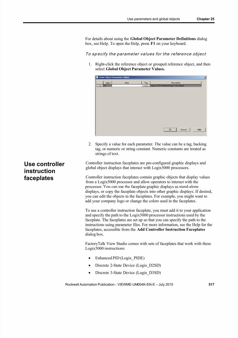
8/15/2019 Factory Talk View ME
http://slidepdf.com/reader/full/factory-talk-view-me 517/635
Use parameters and global objects Chapter 25
Rockwell Automation Publication - VIEWME-UM004K-EN-E – July 2015 517
For details about using the Global Object Parameter Definitions dialog box, see Help. To open the Help, press F1 on your keyboard.
To sp eci fy the parameter va lues for the reference objec t
1. Right-click the reference object or grouped reference object, and thenselect Global Object Parameter Values.
2. Specify a value for each parameter. The value can be a tag, backingtag, or numeric or string constant. Numeric constants are treated asstrings of text.
Controller instruction faceplates are pre-configured graphic displays andglobal object displays that interact with Logix5000 processors.
Controller instruction faceplates contain graphic objects that display valuesfrom a Logix5000 processor and allow operators to interact with the
processor. You can use the faceplate graphic displays as stand-alonedisplays, or copy the faceplate objects into other graphic displays. If desired,you can edit the objects in the faceplates. For example, you might want toadd your company logo or change the colors used in the faceplates.
To use a controller instruction faceplate, you must add it to your applicationand specify the path to the Logix5000 processor instructions used by thefaceplate. The faceplates are set up so that you can specify the path to theinstructions using parameter files. For more information, see the Help for the
faceplates, accessible from the Add Controller Instruction Faceplates dialog box.
FactoryTalk View Studio comes with sets of faceplates that work with theseLogix5000 instructions:
Enhanced PID (Logix_PIDE)
Discrete 2-State Device (Logix_D2SD)
Discrete 3-State Device (Logix_D3SD)
Use controller
instructionfaceplates
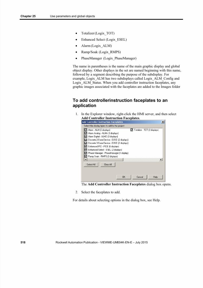
8/15/2019 Factory Talk View ME
http://slidepdf.com/reader/full/factory-talk-view-me 518/635
Chapter 25 Use parameters and global objects
518 Rockwell Automation Publication - VIEWME-UM004K-EN-E – July 2015
Totalizer (Logix_TOT)
Enhanced Select (Logix_ESEL)
Alarm (Logix_ALM)
Ramp/Soak (Logix_RMPS)
PhaseManager (Logix_PhaseManager)
The name in parentheses is the name of the main graphic display and globalobject display. Other displays in the set are named beginning with this name,followed by a segment describing the purpose of the subdisplay. Forexample, Logix_ALM has two subdisplays called Logix_ALM_Config andLogix_ALM_Status. When you add controller instruction faceplates, anygraphic images associated with the faceplates are added to the Images folder
To add controllerinstruction faceplates to anapplication
1. In the Explorer window, right-click the HMI server, and then selectAdd Controller Instruction Faceplates .
The Add Controller Instruction Faceplates dialog box opens.
2. Select the faceplates to add.
For details about selecting options in the dialog box, see Help.
8/15/2019 Factory Talk View ME
http://slidepdf.com/reader/full/factory-talk-view-me 519/635
Rockwell Automation Publication - VIEWME-UM004K-EN-E – July 2015 519
Chapter 26
Set up data logging
This chapter describes:
Steps for setting up data logging
Data log files
Data log models
Change the data log model used at run time
Show data logs using the trend graphic object
Problems with data logging
Follow these steps to set up data logging:
1. In the Data Log Models editor, set up a data log model that specifieshow many log values to store, the conditions that trigger data logging,where to log data, and which tags to monitor.
2. In the Startup editor, turn on data logging by selecting the Datalogging check box. Also use this editor to specify the data log model to
use at run time. See Create runtime applications on page 221 .
3. In the Graphics editor, create a graphic display containing the trendgraphic object, and set up how the object looks, which tag values toshow, the start time, and the time span for the data. Also specify thename of the data log model to use.
As soon as the application starts running, FactoryTalk View begins loggingtag values to the data log files. When the maximum number of data pointshave been logged, the oldest data is deleted to make room for the new data.FactoryTalk View supplies data from the log files to the trend object for therequested tags and time span.
The data log files are retained when you restart an application after ashutdown or power loss. You can delete the log files from the runtimecomputer at application startup.
Use data logging to keep a permanent record of tag data. You can record tagdata as tag values change, or on a periodic basis (for example, every minute).
For information about deleting the log files, see Delete log files on theruntime computer on page 243 .
Steps for setting updata logging
Data log files

8/15/2019 Factory Talk View ME
http://slidepdf.com/reader/full/factory-talk-view-me 520/635
Chapter 26 Set up data logging
520 Rockwell Automation Publication - VIEWME-UM004K-EN-E – July 2015
File names
FactoryTalk View creates two data log files:
Data Log Model Name .log
Data Log Model Name .tag
You’ll need this information if you log to a custom path and want to deletethe log files manually.
A data log model defines which tags to log data for, as well as how andwhere the data is logged.
You can set up multiple data log models, but you can run only one data logmodel at a time. For information about running a different data log model,
see Change the data log model used at run time on page 522 .
Create Data Log Models
Use the Data Log Models editor to create one or more data log models. Eachdata log model is a file stored in the editor’s folder. You can open and workon multiple models at the same time.
For detailed information about the options in the Data Log Models editor,see Help.
Each data log model has a unique name, and an optional description.
You can log a maximum of 1,000,000 points for version 7.00.00 or later, andyou can log 300,000 points for release versions earlier than 7.00.00. The
Data Log Models

8/15/2019 Factory Talk View ME
http://slidepdf.com/reader/full/factory-talk-view-me 521/635
Set up data logging Chapter 26
Rockwell Automation Publication - VIEWME-UM004K-EN-E – July 2015 521
default is 1000. When the maximum number of data points have beenlogged, the oldest data is deleted to make room for the new data.
Data storage locations
You can store data log files in any one of these locations:
On the runtime computer
On another computer on the network
On a compact Flash Card (for PanelView Plus or PanelView Plus CEterminals only)
If the logging destination is unavailable for any reason, for example, the cardis removed or the network drive becomes unavailable, data logging stops. Itdoes not restart until you restart the application.
Log to a ne twork loca t ion
To log data to a network location, the network drive must be shared, and theruntime computer must be logged in to the same domain as the computer onthe network. To do this, the user must have access rights for the domain.
The PanelView Plus or PanelView Plus CE terminal cannot be part of adomain. However, you can verify that the user who is logged into thePanelView Plus or PanelView Plus CE terminal is on a user list that is part of
a domain.For more information about logging in to a Windows domain orauthenticating users, see Log in to the application on page 263 .
Data logging methods
There are two methods for triggering data logging. You can set up logging sotag values are logged:
Periodically (periodic logging)
Only when a tag value changes (on-change logging)
Log per iodica l ly
Periodic logging is used to take a snapshot of all tag values at a particular point in time. Tag values are logged even if there has been no change.
You cannot change the periodic log rate at run time.

8/15/2019 Factory Talk View ME
http://slidepdf.com/reader/full/factory-talk-view-me 522/635
Chapter 26 Set up data logging
522 Rockwell Automation Publication - VIEWME-UM004K-EN-E – July 2015
Log on change
On-change logging is used to log only tags whose values have changed.
For HMI tags, before logging occurs, the change must equal a specified percentage of change in the tag value. The percentage is based on HMI tags’minimum and maximum values as set up in the Tags editor. Only the tagsthat change by the specified percentage are logged. If you specify a
percentage of 0, all changes are logged.
If a tag does not have a minimum or maximum attribute (for example a dataserver tag in Logix5000), when you specify on-change logging, all changesare logged for that tag. You don’t need to specify a percentage.
Use a heartb eat rate
You can also specify a heartbeat rate, to log values at specified times even ifno tag value changes have occurred. The heartbeat ensures that the data inthe log file is current. The heartbeat is also a good way to ensure that datalogging is working and acquiring valid data.
The heartbeat cannot be less than the maximum update rate, which is the rateat which data servers send tag values to FactoryTalk View.
If you specify a heartbeat of 0, the heartbeat is not used.
Tags in the data log modelThe data log model can contain up to 100 analog or digital tags, including
both HMI and data server tags.
You cannot use string tags, array tags, tag placeholders, parameters, orexpressions in your data log model.
Dele te tags f rom the mo del
If you delete a tag from the data log model, previously logged data for the tagis not accessible unless you add the tag back to the model.
Your application can run only one data log model at a time. Follow this procedure to switch data log models.
To run a different data log model
1. Shut down the application.
2. Start FactoryTalk View Studio and open the application.
Change the data logmodel used at runtime

8/15/2019 Factory Talk View ME
http://slidepdf.com/reader/full/factory-talk-view-me 523/635
Set up data logging Chapter 26
Rockwell Automation Publication - VIEWME-UM004K-EN-E – July 2015 523
3. In the Startup editor, specify the new data log model.
4. Create the runtime application. See Create runtime applications on page 221 .
5. Transfer the runtime application to the runtime platform.
For information about transferring applications to:
A personal computer, see Run applications on a personal computer on page 229 .
A PanelView Plus or PanelView Plus CE terminal, see Transferapplications to a PanelView Plus terminal on page 247 .
6. Run the new application.
You can use the trend graphic object to show the data that you have logged.At run time, when the operator opens a graphic display containing a trend,the trend shows values from the data log file for the data log model that isrunning. The data log model specifies which data to collect in the data logfile.
In addition to showing historical values from the data log file, trends canshow current values for the tags in the model. Trends can also show currentvalues for tags or expressions that are not in a data log model. For moreinformation about trends, see Set up trends on page 535 .
Problems with data logging occur under these circumstances:
When your application starts at run time, if any of the tags specified inthe current data log model do not exist, an error message is sent toFactoryTalk Diagnostics.
If the data log file is corrupted or invalid, the file is deleted andrecreated, and an error message is sent to FactoryTalk Diagnostics.
If logging to a folder on a networked computer, and the runtimecomputer is not logged in to the Windows domain of the networkcomputer, the log folder cannot be created. An error message is sent toFactoryTalk Diagnostics.
If logging to an invalid path, the log folder cannot be created. An errormessage is sent to FactoryTalk Diagnostics. One of the reasons that the
path might be invalid is that the top-level folder of the path is notshared.
When the application starts, FactoryTalk View checks whether there isdisk space to store the data log model’s data. If there is not enoughspace, an error message is sent to FactoryTalk Diagnostics and datalogging does not start.
Show data logsusing the trendgraphic object
Problems with datalogging

8/15/2019 Factory Talk View ME
http://slidepdf.com/reader/full/factory-talk-view-me 524/635
Chapter 26 Set up data logging
524 Rockwell Automation Publication - VIEWME-UM004K-EN-E – July 2015

8/15/2019 Factory Talk View ME
http://slidepdf.com/reader/full/factory-talk-view-me 525/635
Rockwell Automation Publication - VIEWME-UM004K-EN-E – July 2015 525
Chapter 27
Use information messages
This chapter describes:
Steps for setting up information messages
Use the Information Messages and Information Setup editors
Prepare to set up information messages
How information messages work
Create information messages in multiple languages
The [INFORMATION] display
Create your own information message display
Open and close the information message display
How the information message display graphic object works
Change the information message file used at run time
Use information messages to give the operator messages about the process, prompts or instructions, and information about current states.
Information messages versus local messages
Use information messages to give the operator information no matter whichdisplay is open. To give the operator information in a specific graphic displaywhile the display is open, use local messages.
For details about local messages, see Use local messages on page 325 .
Follow these steps to set up information messages:
1. In the Information Messages editor, set up the messages and theirtrigger values.
2. In the Information Setup editor, specify the graphic display to openwhen information messages occur, and the file of messages to show.
3. Also use this editor to assign a tag or expression to the Valueconnection. If you want the operator to acknowledge messages, assignthe Ack connection and specify the acknowledge hold time.
About informationmessages
Steps for setting up
informationmessages
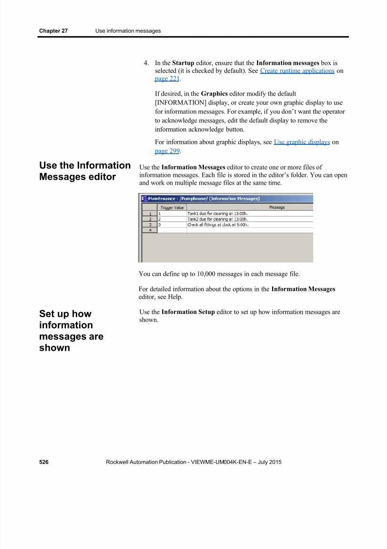
8/15/2019 Factory Talk View ME
http://slidepdf.com/reader/full/factory-talk-view-me 526/635
Chapter 27 Use information messages
526 Rockwell Automation Publication - VIEWME-UM004K-EN-E – July 2015
4. In the Startup editor, ensure that the Information messages box isselected (it is checked by default). See Create runtime applications on
page 221 .
If desired, in the Graphics editor modify the default[INFORMATION] display, or create your own graphic display to usefor information messages. For example, if you don’ t want the operatorto acknowledge messages, edit the default display to remove theinformation acknowledge button.
For information about graphic displays, see Use graphic displays on page 299 .
Use the Information Messages editor to create one or more files ofinformation messages. Each file is stored in the editor’s folder. You can openand work on multiple message files at the same time.
You can define up to 10,000 messages in each message file.
For detailed information about the options in the Information Messages editor, see Help.
Use the Information Setup editor to set up how information messages areshown.
Use the InformationMessages editor
Set up howinformationmessages areshown
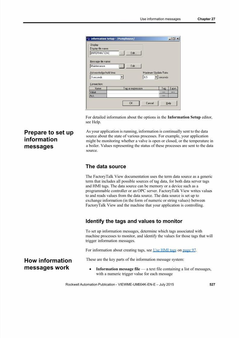
8/15/2019 Factory Talk View ME
http://slidepdf.com/reader/full/factory-talk-view-me 527/635
Use information messages Chapter 27
Rockwell Automation Publication - VIEWME-UM004K-EN-E – July 2015 527
For detailed information about the options in the Information Setup editor,see Help.
As your application is running, information is continually sent to the datasource about the state of various processes. For example, your applicationmight be monitoring whether a valve is open or closed, or the temperature ina boiler. Values representing the status of these processes are sent to the datasource.
The data source
The FactoryTalk View documentation uses the term data source as a genericterm that includes all possible sources of tag data, for both data server tagsand HMI tags. The data source can be memory or a device such as a
programmable controller or an OPC server. FactoryTalk View writes valuesto and reads values from the data source. The data source is set up toexchange information (in the form of numeric or string values) betweenFactoryTalk View and the machine that your application is controlling.
Identify the tags and values to monitor
To set up information messages, determine which tags associated withmachine processes to monitor, and identify the values for those tags that willtrigger information messages.
For information about creating tags, see Use HMI tags on page 97 .
These are the key parts of the information message system:
Information message file — a text file containing a list of messages,with a numeric trigger value for each message
Prepare to set upinformationmessages
How informationmessages work

8/15/2019 Factory Talk View ME
http://slidepdf.com/reader/full/factory-talk-view-me 528/635
Chapter 27 Use information messages
528 Rockwell Automation Publication - VIEWME-UM004K-EN-E – July 2015
Information message display — a graphic display that opens at runtime and shows information messages
Value connection — a tag or expression. When the value of this
connection matches a message’s trigger value, the information messagedisplay opens with the associated message shown.
The following example shows how the key parts of the information messagesystem work together.
Example: Set up the data source to show information messages
This example shows how to set up the data source to notify the operator thata conveyor belt has stopped. In this example, the status of two conveyor beltsis being monitored. You can use both HMI and data server tags.
1. Create a digital tag called Conveyor_1_status. This tag points to anaddress in a programmable controller that is linked to a sensor on thefirst conveyor belt. When t he belt is running, the tag’s value is 0. Whenthe belt stops running, the value changes to 1.
2. Create a second digital tag called Conveyor_2_status. This tag pointsto an address in a programmable controller that is linked to a sensor onthe second convey or belt. When the belt is running, the tag’s value is 0.When the belt stops running, the value changes to 1.
3. Create an analog tag called Information_messages. Set up the datasource to send a value of 1 to this tag when Conveyor_1_status has avalue of 1, and to send a value of 2 to this tag when theConveyor_2_status tag has a value of 1.
4. In the Information Messages editor, create these messages withtrigger values matching the values that will be sent to theInformation_messages tag:
Trigger value Message
1 Conveyor belt 1 has stopped.
2 Conveyor belt 2 has stopped.
5. Save the message file with the name Conveyor belts .
6. In the Information Setup editor, assign the Information_messagestag to the Value connection, and select the Conveyor belts message file.
At run time, when the value of Conveyor_1_status changes to 1, the firstmessage is shown (in the default information message display). When thevalue of Conveyor_2_status changes to 1, the second message is shown.

8/15/2019 Factory Talk View ME
http://slidepdf.com/reader/full/factory-talk-view-me 529/635
Use information messages Chapter 27
Rockwell Automation Publication - VIEWME-UM004K-EN-E – July 2015 529
Information messages and trigger values
Create messages associated with each tag value change that you want toinform the operator about. Assign each message a trigger value, and set upthe data source to send the trigger value to the Value connection. You canuse both HMI and data server tags.
The trigger value can be any non-zero integer value (positive or negative).Trigger values do not need to be contiguous, but they must be unique foreach message. For example, you could use trigger values of 1, 2, and 3, orvalues of 10, 20, and 30.
Trigger values cannot be 0. Digital tags have two possible values, 0 and 1.Therefore, if you use a digital tag you can only use the value 1 to trigger amessage. If you want to use a digital tag to trigger two different messages,create an expression that adds 1 to the digital tag’s value. That way, you canuse the trigger values 1 and 2.
If you use an analog tag or an expression, you can use any non-zero integeror floating-point value to trigger an alarm. Floating-point values are roundedto the nearest integer. For information about how values are rounded, seeHow values are rounded on page 98 .
You can create multiple information message files, but you can use only onemessage file at run time. For information about using a different messagefile, see Change the message file used at run time on page 532 .
FactoryTalk View 5.00 and later supports information messages in multiple
languages. When you create information messages, they are in the currentapplication language. You can export the information messages fortranslation and then import them back into the application. For details, seeSet up language switching on page 197 .
Language switching information messages inFactoryTalk View ME Station 4.00
For applications that will run in FactoryTalk View ME Station version 4.00,use the CurrentLanguage( ) expression function to specify message offsets inthe information message file. In the file, divide your messages into sectionsfor each language. For information about the CurrentLanguage( ) function,see Language function on page 487 .
Create informationmessages inmultiple languages
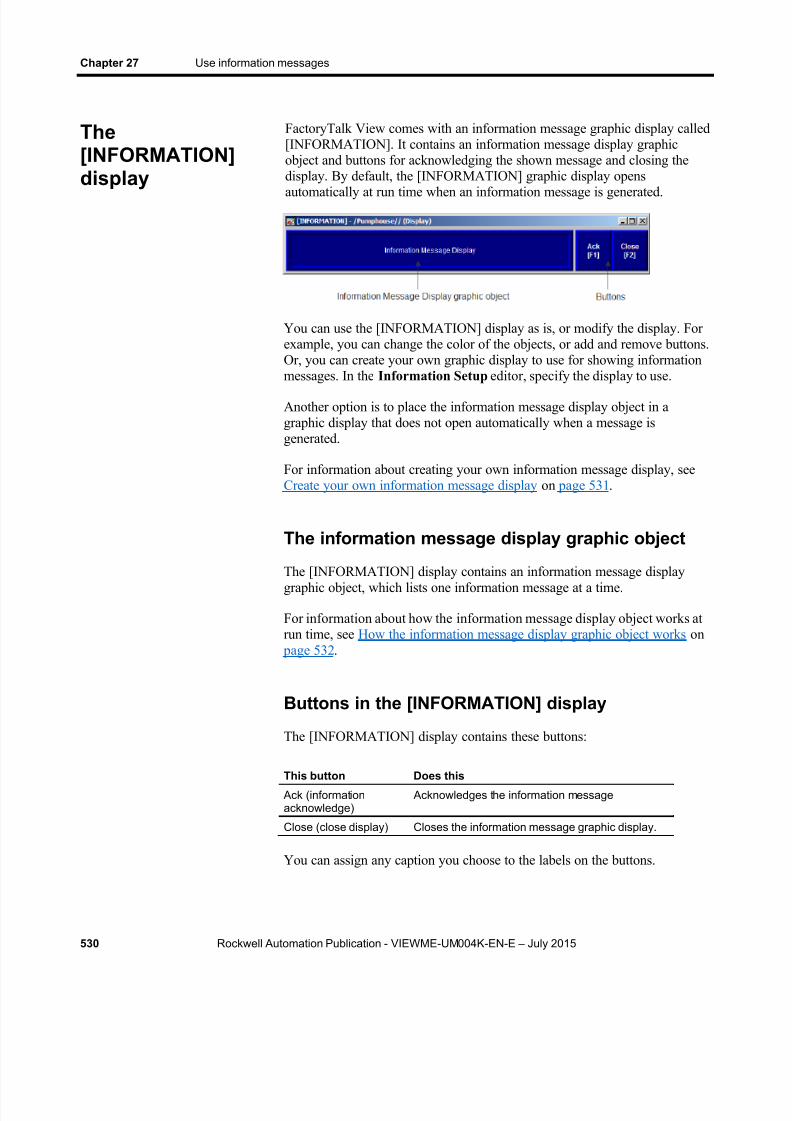
8/15/2019 Factory Talk View ME
http://slidepdf.com/reader/full/factory-talk-view-me 530/635
Chapter 27 Use information messages
530 Rockwell Automation Publication - VIEWME-UM004K-EN-E – July 2015
FactoryTalk View comes with an information message graphic display called[INFORMATION]. It contains an information message display graphicobject and buttons for acknowledging the shown message and closing thedisplay. By default, the [INFORMATION] graphic display opens
automatically at run time when an information message is generated.
You can use the [INFORMATION] display as is, or modify the display. Forexample, you can change the color of the objects, or add and remove buttons.Or, you can create your own graphic display to use for showing informationmessages. In the Information Setup editor, specify the display to use.
Another option is to place the information message display object in agraphic display that does not open automatically when a message isgenerated.
For information about creating your own information message display, seeCreate your own information message display on page 531 .
The information message display graphic object
The [INFORMATION] display contains an information message displaygraphic object, which lists one information message at a time.
For information about how the information message display object works atrun time, see How the information message display graphic object works on
page 532 .
Buttons in the [INFORMATION] display
The [INFORMATION] display contains these buttons:
This button Does this
Ack (informationacknowledge)
Acknowledges the information message
Close (close display) Closes the information message graphic display.
You can assign any caption you choose to the labels on the buttons.
The[INFORMATION]display
8/15/2019 Factory Talk View ME
http://slidepdf.com/reader/full/factory-talk-view-me 531/635
Use information messages Chapter 27
Rockwell Automation Publication - VIEWME-UM004K-EN-E – July 2015 531
Use the information acknowledge button
When the operator presses the information acknowledge button, if the Ackconnection is assigned, the connection value is set to 1 at the data source.The value is held as long as the operator presses the button, or for theacknowledge hold time, whichever is longer. Then the connection is reset to0.
You can create your own graphic display for showing information messages,containing an information message display graphic object and the buttonsyou want to use in the display.
If you create your own graphic display, use an On Top display and select theCannot Be Replaced option.
For more information about the information message display graphic object,
see How the information message display graphic object works on page 532 .
For information about creating graphic displays and graphic objects, see Usegraphic displays on page 299 and Use graphic objects on page 331 .
Open the display
The information message display you specify in the Information Setup editor (either the default [INFORMATION] display or your own display) isautomatically opened whenever the Value connection value matches atrigger value.
You can also create a Goto display button that the operator can press to openthe information message display. For information about setting up a Gotodisplay button and specifying the display to open, see Help.
Close the display
The information message display closes when the Value connection valuechanges to 0.
To automatically close the display when the operator acknowledges amessage, set up the data source to set the Value connection to 0 when theAck connection is set to 1.
The operator can also close the display by pressing a close display button.
Create your owninformationmessage display
Open and close theinformationmessage display

8/15/2019 Factory Talk View ME
http://slidepdf.com/reader/full/factory-talk-view-me 532/635
Chapter 27 Use information messages
532 Rockwell Automation Publication - VIEWME-UM004K-EN-E – July 2015
At run time, when the Value connection at the data source changes from 0 toa non-zero value, the assigned information message display opens. If thevalue matches a message’s trigger value, the associated information messageappears in the information message display graphic object. The object can be
in the default [INFORMATION] display, in an information message displayyou have created, or can be placed in any display in your application.
For information about setting up the information message display graphicobject, see Set up information message displays on page 454 .
What is shown
If the Value connection is unassigned, the information messagegraphic display never opens automatically. If the operator opens agraphic display containing an information message display object, theobject is blank.
The Value connection is rounded up to the nearest integer. If the valuedoes not match any of the trigger values in the specified message file,the display is filled with question marks (?).
For information about how values are rounded, see How values arerounded on page 98 .
If the message is too long to fit in the information message displayobject, the last shown character is replaced with an asterisk (*).
When the Value connection value is 0, the information message
graphic display is closed. If you set up information messages in multiple languages, messages are
shown in the current application language. When a language switchoccurs, a message that was already in the information message displayremains in the language that it originally appeared in. New messagesare shown in the new language.
Your application can use only one message file at a time. Follow this procedure to switch message files.
1. Shut down the application.
2. Start FactoryTalk View Studio and open the application.
3. In the Information Setup editor, specify the new information messagefile.
4. Create the runtime application. See Create runtime applications on page 221 .
5. Transfer the runtime application to the runtime platform.
How the informationmessage displaygraphic objectworks
Change themessage file usedat run time

8/15/2019 Factory Talk View ME
http://slidepdf.com/reader/full/factory-talk-view-me 533/635
Use information messages Chapter 27
Rockwell Automation Publication - VIEWME-UM004K-EN-E – July 2015 533
For information about transferring applications to:
A personal computer, see Run applications on a personal computer on page 229 .
A PanelView Plus or PanelView Plus CE terminal, see Transferapplications to a PanelView Plus terminal on page 247 .
6. Run the new application.

8/15/2019 Factory Talk View ME
http://slidepdf.com/reader/full/factory-talk-view-me 534/635
Chapter 27 Use information messages
534 Rockwell Automation Publication - VIEWME-UM004K-EN-E – July 2015

8/15/2019 Factory Talk View ME
http://slidepdf.com/reader/full/factory-talk-view-me 535/635
Rockwell Automation Publication - VIEWME-UM004K-EN-E – July 2015 535
Chapter 28
Set up trends
This chapter describes:
What trends are.
Summary of steps for creating a trend graphic object.
Create trends, and the Trend Object Properties dialog box.
The parts of the trend graphic object.
The different chart types.
Choose colors, fonts, lines, and markers for the trend.
Test the trend.
Use objects from the Trends graphic library.
Use buttons to control the trend at run time.
Print trend data.
Runtime errors for trends.
A trend is a visual representation of current or historical tag values. Thetrend provides operators with a way of tracking plant activity as it ishappening.
You can:
Plot data for as many as eight tags or expressions on one trend.
Create a trend that is part of a graphic display or acts as the entiregraphic display.
Plot data over time, or plot one variable against another in an XY Plotchart to show the relationship between them.
Show isolated or non-isolated graphs. Isolated graphing places each pen in a separate band of the chart. With non-isolated graphing, penvalues can overlap.
Create buttons to allow the operator to pause, scroll, and print the trenddata.
About trends

8/15/2019 Factory Talk View ME
http://slidepdf.com/reader/full/factory-talk-view-me 536/635
Chapter 28 Set up trends
536 Rockwell Automation Publication - VIEWME-UM004K-EN-E – July 2015
The illustration below shows a trend that has been added to a graphic display.You can view the following display by opening the InstantFizz_ME sampleapplication.
Current versus historical data
The data shown in a trend can come from two sources. For current values,data comes from the value table as it is collected. The value table is a recordof the most recent values collected from the data source, and is stored intemporary memory while the application is running.
For historical values, data comes from a data log model’s log file, if a modelis assigned to the trend. You can show both current and historical data in thesame trend.
For information about data log models, see Set up data logging on page 519 .
Time, date, and number formats
The trend is shown using the time, date, and number formats of the currentapplication language. For example, if the application language uses a commafor the decimal symbol, the scale on the y-axis uses commas for the decimalsymbol.
For information about using multiple languages, see Set up languageswitching on page 197 .
8/15/2019 Factory Talk View ME
http://slidepdf.com/reader/full/factory-talk-view-me 537/635
Set up trends Chapter 28
Rockwell Automation Publication - VIEWME-UM004K-EN-E – July 2015 537
Follow these steps to create a trend:
1. To plot historical data, create a data log model in the Data LogModels editor. For information, see Set up data logging on page 519 .
2. Create a trend graphic object in the Graphics editor, as described onCreate trend objects on page 537 .
3. Set up the trend in the Trend Object Properties dialog box. Fordetails about the options in the dialog box, see Help.
4. If desired, create a next pen button, a pause button, or key buttons inthe same graphic display, to allow the operator to switch between pens,
pause the trend, or scroll the trend.
For information about the buttons you can use with trends, see Use
buttons to control the trend at run time on page 545 .
5. To keep a printed record of the trend data, provide a way for theoperator to print the graphic display. For information see Print trenddata on page 546 .
To create a trend object
1. In the Graphics editor, create or open a graphic display.
2. Select the Trend drawing tool by doing one of the following:
In the Objects toolbox, click the Trend tool.
From the Objects menu, select Trending > Trend .
3. Drag the mouse to create a box approximately the size you want for thetrend.
4. Double-click the trend to open the Trend Object Properties dialog box.
5. Set up the trend. For details, see Help.
Once you have set up the trend, you can edit it as you would any othergraphic object. You can move it, resize it, attach animation to it, and so on.You can also use this object in other graphic displays by dragging it from onedisplay and dropping it into another.
For more information about graphic objects, see Use graphic objects on page331 .
Steps for creating atrend
Create trend objects
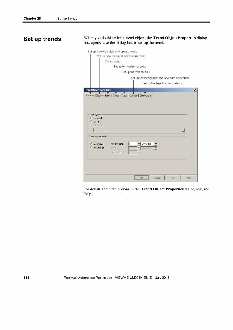
8/15/2019 Factory Talk View ME
http://slidepdf.com/reader/full/factory-talk-view-me 538/635
Chapter 28 Set up trends
538 Rockwell Automation Publication - VIEWME-UM004K-EN-E – July 2015
When you double-click a trend object, the Trend Object Properties dialog box opens. Use the dialog box to set up the trend.
For details about the options in the Trend Object Properties dialog box, seeHelp.
Set up trends
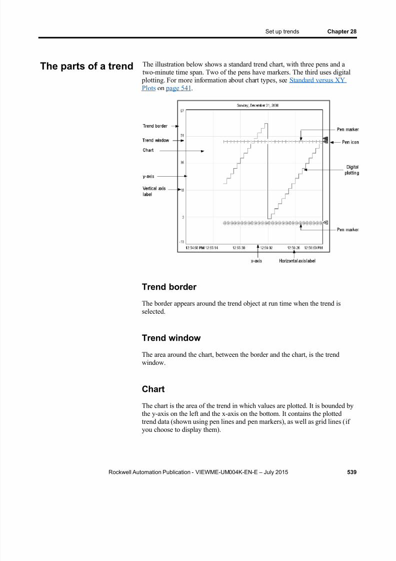
8/15/2019 Factory Talk View ME
http://slidepdf.com/reader/full/factory-talk-view-me 539/635
Set up trends Chapter 28
Rockwell Automation Publication - VIEWME-UM004K-EN-E – July 2015 539
The illustration below shows a standard trend chart, with three pens and atwo-minute time span. Two of the pens have markers. The third uses digital
plotting. For more information about chart types, see Standard versus XYPlots on page 541 .
Trend borderThe border appears around the trend object at run time when the trend isselected.
Trend window
The area around the chart, between the border and the chart, is the trendwindow.
Chart
The chart is the area of the trend in which values are plotted. It is bounded bythe y-axis on the left and the x-axis on the bottom. It contains the plottedtrend data (shown using pen lines and pen markers), as well as grid lines (ifyou choose to display them).
The parts of a trend
8/15/2019 Factory Talk View ME
http://slidepdf.com/reader/full/factory-talk-view-me 540/635
Chapter 28 Set up trends
540 Rockwell Automation Publication - VIEWME-UM004K-EN-E – July 2015
Y-axis
The y-axis is the left vertical edge of the chart. It is also known as the verticalaxis.
Vertical axis labels
The vertical axis labels show the scale (range) of values for the pens. Ifdesired, you can set up the trend to omit the vertical axis labels.
The minimum and maximum values for the scale can be determinedautomatically (using the best fit for the current data), be derived from a pen’sminimum and maximum values, use a constant value, or be controlled bytags.
You can set up the trend so all pens use the same scale, or use individualranges for each pen. If you choose the latter method, create a next pen buttonin the graphic display, to allow operators to view the range for each pen.When the operator presses the button, the vertical axis changes to the new
pen’s range.
For example, if Pen 1 has a minimum value of 10 and a maximum value of100, the range on the vertical axis is 10 to 100 when the pen is selected. IfPen 2 has a minimum of -10 and a maximum of 50, the range on the verticalaxis changes to -10 to 50 when the operator presses the next pen button.
X-axis
The x-axis is the bottom horizontal edge of the chart. It is also known as thehorizontal axis.
Horizontal axis labels
For standard charts, the horizontal axis labels indicate the time span covered by the trend. For XY Plot charts, the horizontal axis labels show the scale(range) of values for the pen selected to serve as the x-axis pen.
If desired, you can set up the trend to omit the horizontal axis labels. Thenumber of labels depends on the size of the trend object and the number ofvertical grid lines.
Pens
Pens are the lines and symbols used to represent values. The values can betags you are monitoring, expressions that manipulate tag values, or constants.

8/15/2019 Factory Talk View ME
http://slidepdf.com/reader/full/factory-talk-view-me 541/635
Set up trends Chapter 28
Rockwell Automation Publication - VIEWME-UM004K-EN-E – July 2015 541
If there is no data for a pen, or if the data is outside the vertical axis range,the pen does not appear in the chart.
Pen icons
Pen icons appear at the right edge of the chart at run time, if you choose toshow them. The icon’s position indicates the pen’s most recent recordedvalue (from the value table), even if the trend is paused or if the most recentvalue has not been plotted yet.
Pen markers
Pen markers are symbols that indicate data points. If data is plotted
frequently, the markers might not appear as distinct, separate symbols. Forexample, see the lowest pen in the illustration on The parts of a trend on page539 .
Standard versus XY Plots
You can create a standard chart, which plots tag values against time, or anXY Plot chart, which plots one (or more) tag’s values against another’s.
This illustration shows what an XY Plot chart could look like:
Notice that the horizontal axis labels show the range for the specified x-axis pen. The time period covered by the chart is at the upper left.
Chart types

8/15/2019 Factory Talk View ME
http://slidepdf.com/reader/full/factory-talk-view-me 542/635
Chapter 28 Set up trends
542 Rockwell Automation Publication - VIEWME-UM004K-EN-E – July 2015
Isolated graphing
For charts with multiple pens, you can allow the pen values to overlap, oryou can isolate each pen in its own horizontal band on the chart.
This is an example of isolated graphing, with a 10% buffer between each pen’s band:
Notice that in this illustration each pen uses its own scale. If desired, you canuse the same scale for all pens.
With isolated graphing, a grid line is automatically placed above each pen’s band.
Plot a value across the full width of the chart
Use horizontal lines to provide a frame of reference for your tag data. For
example, if you define values that are the limits within which a tag mustoperate, and show horizontal lines in your trend to indicate the limits, when atag crosses one of these limits the tag’s alarm condition is obvious on thetrend.
There are two ways to plot a value across the full width of the chart:
In the Connections tab, assign a constant value to a pen.
When values for the pen have been plotted across the full width of thechart, the pen appears as a solid line.
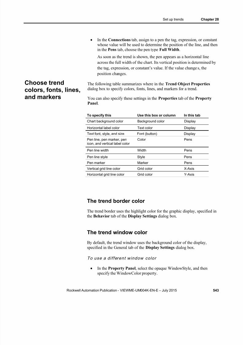
8/15/2019 Factory Talk View ME
http://slidepdf.com/reader/full/factory-talk-view-me 543/635
Set up trends Chapter 28
Rockwell Automation Publication - VIEWME-UM004K-EN-E – July 2015 543
In the Connections tab, assign to a pen the tag, expression, or constantwhose value will be used to determine the position of the line, and thenin the Pens tab, choose the pen type Full Width .
As soon as the trend is shown, the pen appears as a horizontal lineacross the full width of the chart. Its vertical position is determined bythe tag, expression, or constant’s value. If the value change s, the
position changes.
The following table summarizes where in the Trend Object Properties dialog box to specify colors, fonts, lines, and markers for a trend.
You can also specify these settings in the Properties tab of the PropertyPanel .
To specify this Use this box or column In this tab
Chart background color Background color Display
Horizontal label color Text color Display
Text font, style, and size Font (button) Display
Pen line, pen marker, penicon, and vertical label color
Color Pens
Pen line width Width Pens
Pen line style Style Pens
Pen marker Marker Pens
Vertical grid line color Grid color X-Axis
Horizontal grid line color Grid color Y-Axis
The trend border color
The trend border uses the highlight color for the graphic display, specified inthe Behavior tab of the Display Settings dialog box.
The trend window color
By default, the trend window uses the background color of the display,specified in the General tab of the Display Settings dialog box.
To use a d i fferent window color
In the Property Panel , select the opaque WindowStyle, and thenspecify the WindowColor property.
Choose trendcolors, fonts, lines,and markers
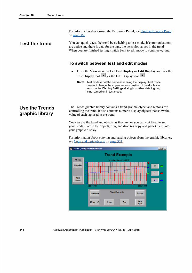
8/15/2019 Factory Talk View ME
http://slidepdf.com/reader/full/factory-talk-view-me 544/635
Chapter 28 Set up trends
544 Rockwell Automation Publication - VIEWME-UM004K-EN-E – July 2015
For information about using the Property Panel , see Use the Property Panel on page 360 .
You can quickly test the trend by switching to test mode. If communications
are active and there is data for the tags, the pens plot values in the trend.When you are finished testing, switch back to edit mode to continue editing.
To switch between test and edit modes
From the View menu, select Test Display or Edit Display , or click theTest Display tool , or the Edit Display tool .
Note: Test mode is not the same as running the display. Test modedoes not change the appearance or position of the display asset up in the Display Settings dialog box. Also, data loggingis not turned on in test mode.
The Trends graphic library contains a trend graphic object and buttons forcontrolling the trend. It also contains numeric display objects that show thevalue of each tag used in the trend.
You can use the trend and objects as they are, or you can edit them to suityour needs. To use the objects, drag and drop (or copy and paste) them intoyour graphic display.
For information about copying and pasting objects from the graphic libraries,see Copy and paste objects on page 374 .
Test the trend
Use the Trendsgraphic library
8/15/2019 Factory Talk View ME
http://slidepdf.com/reader/full/factory-talk-view-me 545/635
Set up trends Chapter 28
Rockwell Automation Publication - VIEWME-UM004K-EN-E – July 2015 545
To use the Trends graphic library
1. Open the Graphics folder, and then open the Libraries folder.
2. Double-click the Trends library.
3. Drag and drop or copy and paste objects into your display.
You can use button graphic objects with the trend, to allow the operator to pause the trend, switch between pens, or scroll the trend. You can link buttons to a specific trend object, or set up a button to work with whicheverobject is selected in the graphic display. For information about linking
buttons to objects, see Link buttons to objects on page 397 .
Use these buttons with trends:
This button Does this
Pause Toggles between pausing and automatic scrolling.When the trend is paused, the pen icons continue to movevertically to indicate the pens’ current values. When the trend resumes scrolling, values that occurred while thetrend was paused are filled in, bringing the trend up to thecurrent time (unless you are scrolling historical data).
Next pen Changes the vertical axis labels to the scale for the next pen.The color of the labels matches the color of the selected pen.
Move up Scrolls up to show higher values on the vertical scale. Forexample, if the visible scale range is 0 to 100, pressing move upcould change the visible range to 10 to 110.The incremental amount the axis scrolls depends on the pen’srange and the number of horizontal grid lines.This button does not work if the Minimum / maximum value option in the Y-Axis tab is set to Automatic .
Move down Scrolls down to show lower values on the vertical scale.This button does not work if the Minimum /maximum valueoption in the Y-Axis tab is set to Automatic .
Move left Pauses the trend and scrolls to the left.
Move right Pauses the trend and scrolls to the right.
Home Pauses the trend and moves to the earliest data in the trend.
End Resumes trend scrolling and moves to the current (latest) data inthe trend.
To see how the buttons work with the trend, open the Trends graphic library(see Use the Trends graphic library on page 544 ), and start test mode.
For information about creating buttons, see Use graphic objects on page 331 . For details about setting up the buttons, see Set up buttons on page 403 .
Use buttons tocontrol the trend atrun time

8/15/2019 Factory Talk View ME
http://slidepdf.com/reader/full/factory-talk-view-me 546/635
Chapter 28 Set up trends
546 Rockwell Automation Publication - VIEWME-UM004K-EN-E – July 2015
To print trend data at run time, provide the operator with a method for printing the graphic display.
You can use these methods to print graphic displays at run time:
Create a display print button. For information about creating graphicobjects, see Use graphic objects on page 331 .
Assign a tag or expression to the Remote Display Print connection (inthe Global Connections editor). When the value of the tag orexpression changes from 0 to a non-zero value, the current display isautomatically printed.
Program the data source to trigger the change as often as you want thedata printed.
For more information about setting up remote display printing, see Set
up global connections on page 111 .
Everything on the screen is printed, including the current display, pop-upwindows, and any visible background applications.
For information about specifying which printer to use at run time forapplications that will run on a personal computer, see Specify the printers touse at run time on page 238 .
For information about specifying printer options for applications that will runon a PanelView Plus 7, PanelView Plus 6, PanelView Plus, PanelView PlusCompact, or PanelView Plus CE terminal, see the PanelView Plus Terminals
User Manual .
Improve clarity of the trend printout
Depending on what type of printer you use, pen lines with a width of 1 pixelmight not appear in the printout. Choose high-contrast colors and wider linewidths to ensure that the trend data prints clearly.
If data for the trend is not available at run time due to communication errors,a message is sent to FactoryTalk Diagnostics.
See Help for information about solving common trend problems.
Print trend data
Runtime errors forthe trend

8/15/2019 Factory Talk View ME
http://slidepdf.com/reader/full/factory-talk-view-me 547/635
Rockwell Automation Publication - VIEWME-UM004K-EN-E – July 2015 547
Chapter 29
Set up RecipePlus
This chapter describes:
What recipes are
Summary of steps for creating a recipe system
How the recipe system works
Specify the runtime location of recipe files
Create recipe files
Compare recipes
Create RecipePlus buttons, selectors, and tables
Test RecipePlus objects
Use objects from the RecipePlus_Components graphic library
Use buttons with the recipe objects
View data values that are saved at run time
A recipe is a set of numeric and string data values (ingredients) that can bedownloaded to their associated tags at the data source. Each ingredient has a pre-set data value assigned to it. The set of data values for all the ingredientsin a recipe is called a data set. The set of numeric and string tags assigned tothe ingredients in the recipe is called a tag set. The ingredients, data sets, andtag sets are stored together in a recipe file.
You can create different pairs of data sets and tag sets for the same set ofingredients. Each pairing of data set with tag set is called a unit. Each unit islike a unique recipe. At run time, the operator can select the unit (recipe) thatapplies to the current operation.
For example, a bakery making whole wheat bread could use the sameingredients and tag sets, but depending on the type of crust desired, could usedifferent data sets to specify different baking temperatures. As anotherexample, you might want to have multiple production lines baking the same
bread. In this case, the data set for all the production lines would be the same, but the tags receiving the recipe information would be different for each production line. Units allow you to combine different tag sets and data setsfor the same set of ingredients.
The FactoryTalk View RecipePlus system allows you to create up to 15,000ingredients, 500 data sets, 50 tag sets, and 2,500 units for each recipe file.
About recipes
8/15/2019 Factory Talk View ME
http://slidepdf.com/reader/full/factory-talk-view-me 548/635
Chapter 29 Set up RecipePlus
548 Rockwell Automation Publication - VIEWME-UM004K-EN-E – July 2015
You can create data sets at development time, edit them at run time, and alsocreate new data sets from tag values at run time. You can write the data setvalues to tags, or write tag values to data sets.
The RecipePlus system can be used for manufacturing food and beverages, but it can also be used for any application where you want to show, edit,download, or save multiple values at once. For example, recipes are used inthe petrochemical and pharmaceutical industries. In the pharmaceuticalindustry, you could use recipes to design flexible packaging, creating recipesthat specify the number of tissues to put in a box or the number of millilitersof shampoo to put in a bottle.
Follow these steps to create a recipe system:
1. In the RecipePlus Setup editor, specify the runtime location for recipefiles. The files can be stored with the application or in a separate
location. For details, see Specify the runtime file location on page 550 .
2. In the RecipePlus Editor , set up ingredients, data sets, tag sets, andunits. You can also specify a percent complete tag and a status tag forthe recipe. For details, see Set up recipe files on page 552 .
3. Create a display in the Graphics editor, containing a RecipePlus selector, table, and buttons. For details, see Create RecipePlus objects on page 555 .
4. If desired, create key buttons in the same graphic display, to allow theoperator to use the selector and table without a keyboard.
For information about the buttons you can use with recipes, see Use buttons with recipe objects on page 557 .
A recipe system consists of a recipe file and the graphic objects used to workwith the ingredients at run time.
RecipePlus selector
Use the RecipePlus selector to select the recipe file and unit to work with.
RecipePlus table
Use the RecipePlus table to show the selected recipe file’s ingredients , tagvalues, and data set values. The operator can edit data set values in the table,unless you select the View only option.
If desired, you can include a Compare column in the table, to compare tagvalues to data sets at a glance. If you choose this option, FactoryTalk View
Steps for creating arecipe system
How the recipesystem works

8/15/2019 Factory Talk View ME
http://slidepdf.com/reader/full/factory-talk-view-me 549/635
Set up RecipePlus Chapter 29
Rockwell Automation Publication - VIEWME-UM004K-EN-E – July 2015 549
shows an X in the Compare column when the tag value and data set valuefor an ingredient differ. Ingredients with an X are listed first.
RecipePlus button
Use the RecipePlus button to perform actions on the selected recipe’singredients. The recipe is selected using the RecipePlus selector object. Setup a separate RecipePlus button for each action you want to perform:
Download — write the data set values to tags, for all the ingredients inthe selected recipe.
Upload — write tag values to the data set, for all the ingredients in theselected recipe. If all values are uploaded successfully, the recipe file issaved.
Upload and Create — write tag values for all the ingredients in theselected recipe to a new data set, creating a new unit. The operator is
prompted for a name for the new unit. If all values are uploadedsuccessfully, the recipe file is saved.
The new data set is named Data Set n, where n is the next availablenumber (starting at 1) that will create a unique data set name.
Restore — show the selected recipe in the RecipePlus table.
Save — save the data set values for the recipe file and unit shown inthe RecipePlus table. If the operator made changes in the data setvalues using the string pop-up keyboard or numeric pop-up keypad, thenew values in the table overwrite existing data set values (if any) forthe unit in the recipe file.
Delete — delete the recipe unit selected in the RecipePlus selectorobject.
Rename — rename the recipe unit selected in the RecipePlus selectorobject.
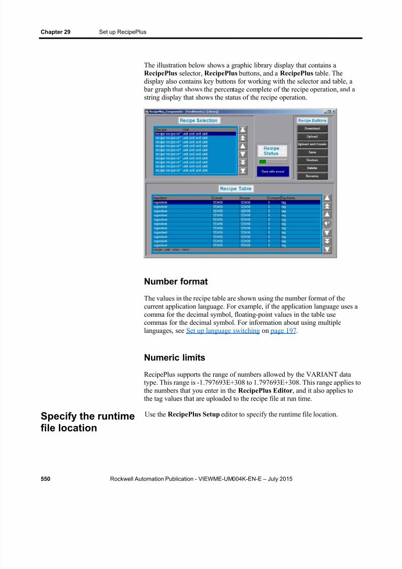
8/15/2019 Factory Talk View ME
http://slidepdf.com/reader/full/factory-talk-view-me 550/635
Chapter 29 Set up RecipePlus
550 Rockwell Automation Publication - VIEWME-UM004K-EN-E – July 2015
The illustration below shows a graphic library display that contains aRecipePlus selector, RecipePlus buttons, and a RecipePlus table. Thedisplay also contains key buttons for working with the selector and table, a
bar graph that shows the percentage complete of the recipe operation, and a
string display that shows the status of the recipe operation.
Number format
The values in the recipe table are shown using the number format of thecurrent application language. For example, if the application language uses acomma for the decimal symbol, floating-point values in the table usecommas for the decimal symbol. For information about using multiplelanguages, see Set up language switching on page 197 .
Numeric limits
RecipePlus supports the range of numbers allowed by the VARIANT datatype. This range is -1.797693E+308 to 1.797693E+308. This range applies tothe numbers that you enter in the RecipePlus Editor , and it also applies tothe tag values that are uploaded to the recipe file at run time.
Use the RecipePlus Setup editor to specify the runtime file location.Specify the runtimefile location
8/15/2019 Factory Talk View ME
http://slidepdf.com/reader/full/factory-talk-view-me 551/635
Set up RecipePlus Chapter 29
Rockwell Automation Publication - VIEWME-UM004K-EN-E – July 2015 551
Store files outside the HMI project
If you store the recipe files outside the HMI project, the runtime applicationcan use updated recipe files without creating a new runtime application(.mer) file.
Storing recipe files outside the HMI project also allows you to useFactoryTalk View Studio to view and edit recipe data that is saved at runtime without converting the .mer file to an .med file. For more information,see View data values that are saved at run time on page 558 .
Note: If you want to store recipe files outside of the HMI project atrun time, make sure you move the files from the application’sRecipePlus folder to the specified runtime location beforerunning the application.
This is the path to the RecipePlus folder: (Windows XP) C:\Documents and Settings\All Users\Shared
Documents\RSView Enterprise\ME\HMI projects\ Projectname \RecipePlus
(Windows Server 2012, Windows 8.1, Windows 8, Windows 7, andWindows Server 2008) C:\Users\Public\Public Documents\RSViewEnterprise\ME\HMI projects\ Project name \RecipePlus
If recipe files are stored outside the HMI project, when you perform anaction on a recipe file at run time, the file is locked until the action iscompleted. This prevents other users from making changes to a file while
you are working with it.
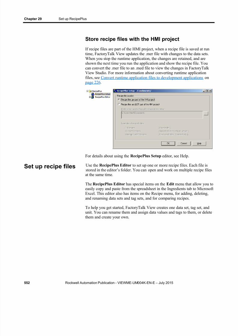
8/15/2019 Factory Talk View ME
http://slidepdf.com/reader/full/factory-talk-view-me 552/635
Chapter 29 Set up RecipePlus
552 Rockwell Automation Publication - VIEWME-UM004K-EN-E – July 2015
Store recipe files with the HMI project
If recipe files are part of the HMI project, when a recipe file is saved at runtime, FactoryTalk View updates the .mer file with changes to the data sets.When you stop the runtime application, the changes are retained, and areshown the next time you run the application and show the recipe file. Youcan convert the .mer file to an .med file to view the changes in FactoryTalkView Studio. For more information about converting runtime applicationfiles, see Convert runtime application files to development applications on
page 226 .
For details about using the RecipePlus Setup editor, see Help.
Use the RecipePlus Editor to set up one or more recipe files. Each file isstored in the editor’s folder. You can open and work on multiple recipe filesat the same time.
The RecipePlus Editor has special items on the Edit menu that allow you toeasily copy and paste from the spreadsheet in the Ingredients tab to MicrosoftExcel. This editor also has items on the Recipe menu, for adding, deleting,and renaming data sets and tag sets, and for comparing recipes.
To help you get started, FactoryTalk View creates one data set, tag set, andunit. You can rename them and assign data values and tags to them, or deletethem and create your own.
Set up recipe files
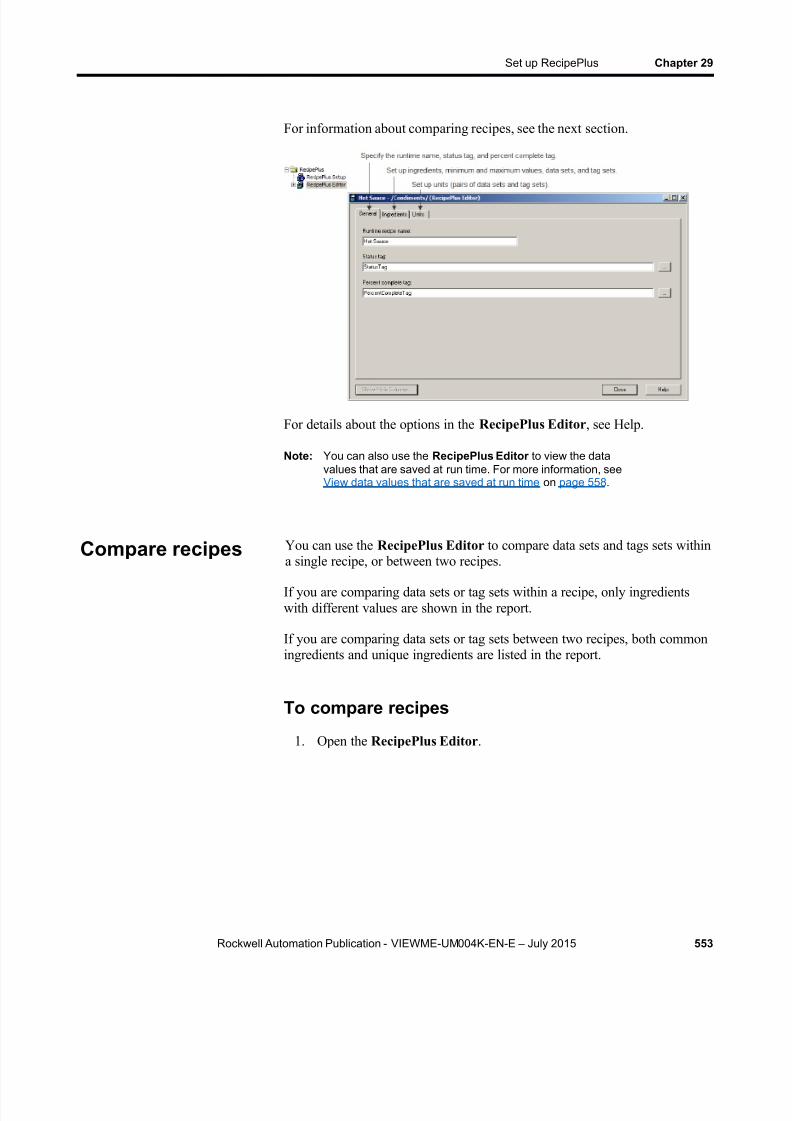
8/15/2019 Factory Talk View ME
http://slidepdf.com/reader/full/factory-talk-view-me 553/635
Set up RecipePlus Chapter 29
Rockwell Automation Publication - VIEWME-UM004K-EN-E – July 2015 553
For information about comparing recipes, see the next section.
For details about the options in the RecipePlus Editor , see Help.
Note: You can also use the RecipePlus Editor to view the datavalues that are saved at run time. For more information, seeView data values that are saved at run time on page 558 .
You can use the RecipePlus Editor to compare data sets and tags sets withina single recipe, or between two recipes.
If you are comparing data sets or tag sets within a recipe, only ingredientswith different values are shown in the report.
If you are comparing data sets or tag sets between two recipes, both commoningredients and unique ingredients are listed in the report.
To compare recipes
1. Open the RecipePlus Editor .
Compare recipes
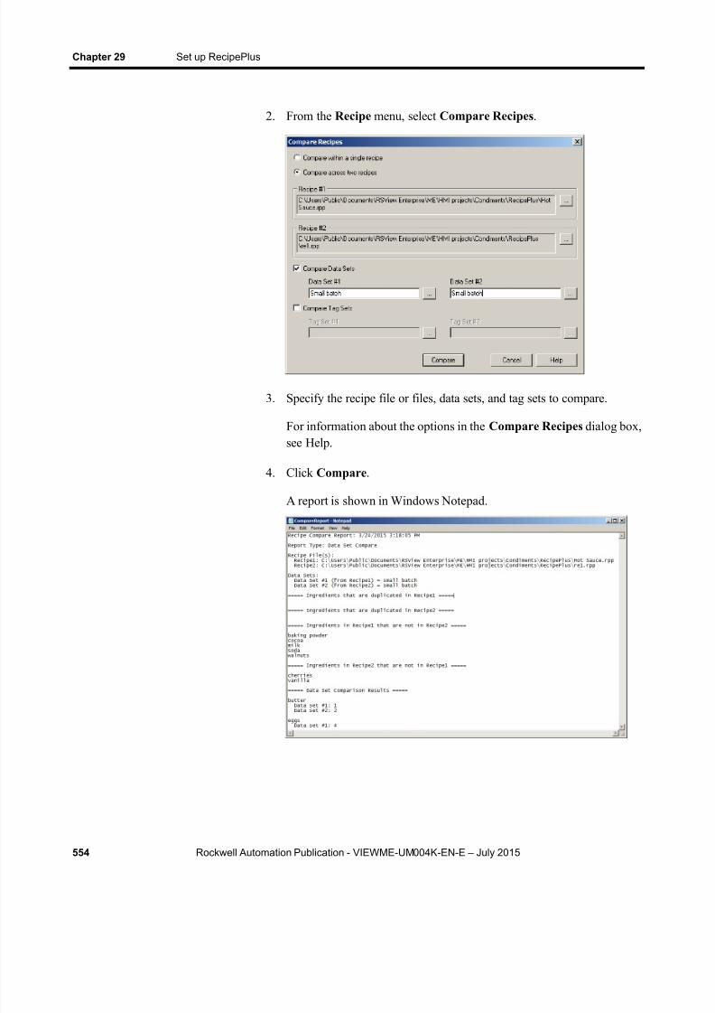
8/15/2019 Factory Talk View ME
http://slidepdf.com/reader/full/factory-talk-view-me 554/635
Chapter 29 Set up RecipePlus
554 Rockwell Automation Publication - VIEWME-UM004K-EN-E – July 2015
2. From the Recipe menu, select Compare Recipes .
3. Specify the recipe file or files, data sets, and tag sets to compare.
For information about the options in the Compare Recipes dialog box,see Help.
4. Click Compare .
A report is shown in Windows Notepad.

8/15/2019 Factory Talk View ME
http://slidepdf.com/reader/full/factory-talk-view-me 555/635
Set up RecipePlus Chapter 29
Rockwell Automation Publication - VIEWME-UM004K-EN-E – July 2015 555
Time and date formats
The time and date in the report use the time and short date format for thecurrent application language. For information about using multiplelanguages, see Set up language switching on page 197 .
You can use the RecipePlus Editor to print recipe data sets. For informationabout printing from editors, see Print on page 51 .
You can create one RecipePlus table and RecipePlus selector per graphicdisplay. You can create multiple RecipePlus buttons in a display, with adifferent action assigned to each.
The objects and button actions to use depend on how you want to use yourrecipe system. For example, if you just want to write data set values to tags,all you need is a RecipePlus selector and a RecipePlus button with the
download action. For information about how the different objects in therecipe system work, see How the recipe system works on page 548 .
To create a recipe object
1. In the Graphics editor, create or open a graphic display.
2. Select a RecipePlus drawing tool by doing one of the following:
In the Objects toolbox, click the RecipePlus Button , RecipePlusSelector , or RecipePlus Table tool.
From the Objects menu, select RecipePlus , and then clickRecipePlus Button , RecipePlus Selector , or RecipePlus Table .
3. Drag the mouse to create a box approximately the size you want for theobject.
4. Double-click the object to open its Properties dialog box.
5. Set up the object. For details, see Help.
Once you have set up a RecipePlus object, you can edit it as you would any
other graphic object. You can move it, resize it, attach animation to it, and soon. You can also use the object in other graphic displays by dragging it fromone display and dropping it into another.
For more information about graphic objects, see Use graphic objects on page331 .
Print recipes
Create RecipePlusobjects
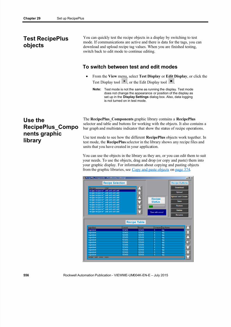
8/15/2019 Factory Talk View ME
http://slidepdf.com/reader/full/factory-talk-view-me 556/635
Chapter 29 Set up RecipePlus
556 Rockwell Automation Publication - VIEWME-UM004K-EN-E – July 2015
You can quickly test the recipe objects in a display by switching to testmode. If communications are active and there is data for the tags, you candownload and upload recipe tag values. When you are finished testing,switch back to edit mode to continue editing.
To switch between test and edit modes
From the View menu, select Test Display or Edit Display , or click theTest Display tool , or the Edit Display tool .
Note: Test mode is not the same as running the display. Test modedoes not change the appearance or position of the display asset up in the Display Settings dialog box. Also, data loggingis not turned on in test mode.
The RecipePlus_Components graphic library contains a RecipePlusselector and table and buttons for working with the objects. It also contains a
bar graph and multistate indicator that show the status of recipe operations.
Use test mode to see how the different RecipePlus objects work together. Intest mode, the RecipePlus selector in the library shows any recipe files andunits that you have created in your application.
You can use the objects in the library as they are, or you can edit them to suityour needs. To use the objects, drag and drop (or copy and paste) them intoyour graphic display. For information about copying and pasting objectsfrom the graphic libraries, see Copy and paste objects on page 374 .
Test RecipePlusobjects
Use theRecipePlus_Components graphiclibrary

8/15/2019 Factory Talk View ME
http://slidepdf.com/reader/full/factory-talk-view-me 557/635
Set up RecipePlus Chapter 29
Rockwell Automation Publication - VIEWME-UM004K-EN-E – July 2015 557
To use the RecipePlus_Components graphiclibrary
1. Open the Graphics folder, and then open the Libraries folder.
2. Double-click the RecipePlus_Components library.
3. Drag and drop or copy and paste objects into your display.
You can use button graphic objects with the RecipePlus selector and table,to select the recipe and unit to work with, and to select ingredients in thetable.
You can link buttons to a specific recipe object, or set up a button to workwith whichever object is selected in the graphic display. For informationabout linking buttons to objects, see Link buttons to objects on page 397 .
Use these buttons with recipe objects:
This button Does this
Move up Moves the highlight bar up one item in the list.
Move down Moves the highlight bar down one item in the list.
Page up Moves the highlight bar up one page in the list.
Page down Moves the highlight bar down one page in the list.
Home Moves the highlight bar to the top item in the list.
End Moves the highlight bar to the bottom item in the list.
Enter (table only) Opens the numeric keypad or string keyboard for the operatorto edit the data set value. If a numeric ingredient has aminimum and maximum value defined, these values are shownin the numeric keypad.If the table is defined as View only, the operator cannot edit it.
To see how the buttons work with the RecipePlus selector and table, openthe RecipePlus_Components graphic library (see Use theRecipePlus_Components graphic library on page 556 ), and start test mode.
For information about creating buttons, see Use graphic objects on page 331 . For details about setting up the buttons, see Set up buttons on page 403 .
Example: Edit and downloading recipe values atrun time
This example shows how to use the RecipePlus graphic objects to edit anddownload recipe values at run time.
Use buttons withrecipe objects

8/15/2019 Factory Talk View ME
http://slidepdf.com/reader/full/factory-talk-view-me 558/635
Chapter 29 Set up RecipePlus
558 Rockwell Automation Publication - VIEWME-UM004K-EN-E – July 2015
1. In the RecipePlus editor, create a RecipePlus file containingingredients, several data sets, a tag set, and several units combining thedifferent data sets with the tag set.
2. Open the RecipePlus_Components library.
3. Start test mode.
4. Use the move up and move down buttons next to the RecipePlus selector to highlight a unit in the selector, and then press the Restore
button.
The unit’s ingredients are shown in the RecipePlus table, with the dataset values in the Recipe column.
5. Use the move up and move down buttons next to the RecipePlus table
to select an ingredient, and then press the Enter button.
The numeric pop-up keypad opens, showing the minimum andmaximum values for the ingredient. If the ingredient is a stringingredient, the string pop-up keyboard opens.
6. Type a new value for the ingredient, and then press Enter.
The new value is shown in the Recipe column.
7. Press the Save button to save the new value.
8. Press the Download button to write all the values in the Recipe columnto the tags associated with the ingredients.
The values are downloaded to the data source.
Use the RecipePlus Editor in FactoryTalk View Studio to view data valuesthat have been saved at run time.
The operator can save tag values at run time by uploading to an existing dataset or to a new data set. The operator can also edit data set values in theRecipePlus table and save the edited values (unless the table is View only).
If recipe files are stored with the HMI project, changes are saved in the .merfile. To view the changes in FactoryTalk View Studio, convert the .mer fileto an .med file. For more information about converting the runtimeapplication file, see Convert runtime application files to developmentapplications on page 226 .
View data valuesthat are saved atrun time
8/15/2019 Factory Talk View ME
http://slidepdf.com/reader/full/factory-talk-view-me 559/635
Set up RecipePlus Chapter 29
Rockwell Automation Publication - VIEWME-UM004K-EN-E – July 2015 559
To view data values in modified recipe files
1. If recipe files are stored outside of the HMI project, do one of thefollowing:
Add the recipe file (*.rpp) that you saved at run time into theapplication using Add Component Into Application (for details, seeAdd components into an application on page 295 ).
If the recipe file already exists in the application, you can just copythe modified file back into the application’s RecipePlus folder.(For the path to the RecipePlus folder, see Store files outside theHMI project on page 551 .)
2. If recipe files are stored with the HMI project, and you have notalready done so, convert the runtime application file to a development
application, as described on Convert runtime application files todevelopment applications on page 226 .
3. In the Explorer window in FactoryTalk View Studio, double-click themodified recipe file.
The RecipePlus Editor opens.
4. Click the Ingredients tab.
5. If the data set you want to view is not visible, scroll right to see moredata sets.

8/15/2019 Factory Talk View ME
http://slidepdf.com/reader/full/factory-talk-view-me 560/635
Chapter 29 Set up RecipePlus
560 Rockwell Automation Publication - VIEWME-UM004K-EN-E – July 2015
8/15/2019 Factory Talk View ME
http://slidepdf.com/reader/full/factory-talk-view-me 561/635
Rockwell Automation Publication - VIEWME-UM004K-EN-E – July 2015 561
Chapter 30
Use macros
This chapter describes:
Use macros to assign values to tags
Use the Macros editor
When to use macros
Running macros when tags or expressions change value
Where to assign macros
A macro is a list of tag assignments stored in a text file, in the format<tag>=<value>. Each assignment assigns a value to a tag. The value can bein the form of another tag, an expression, a numeric constant, or a string.
Examples: Use macros to set tag values
Tag1 = 8Sets the value of Tag1 to 8.
Tank1\Message = "Tank1 overflow"Sets the string tag Tank1\Message to Tank1 overflow.
Tag1 = Tag2Sets the value of Tag1 to be the same as Tag2.
Tag1 = Tag1 + 1Increases the value of Tag1 by 1.
Tag1 = if (Tag2 < Tag1) then 4 else 3Performs the if-then-else calculation and stores the result in Tag1.
1Pump = {Industry-2} + {2Pump}Adds the values of Industry-2 and 2Pump and stores the result in1Pump.
Brackets surround Industry-2 because of the dash in the name. Bracketssurround 2Pump because the name starts with a number. No brackets areused for 1Pump because this name is on the left side of the equal sign.
For more information about expression syntax, see Use expressions on page475 .
Use macros toassign values totags
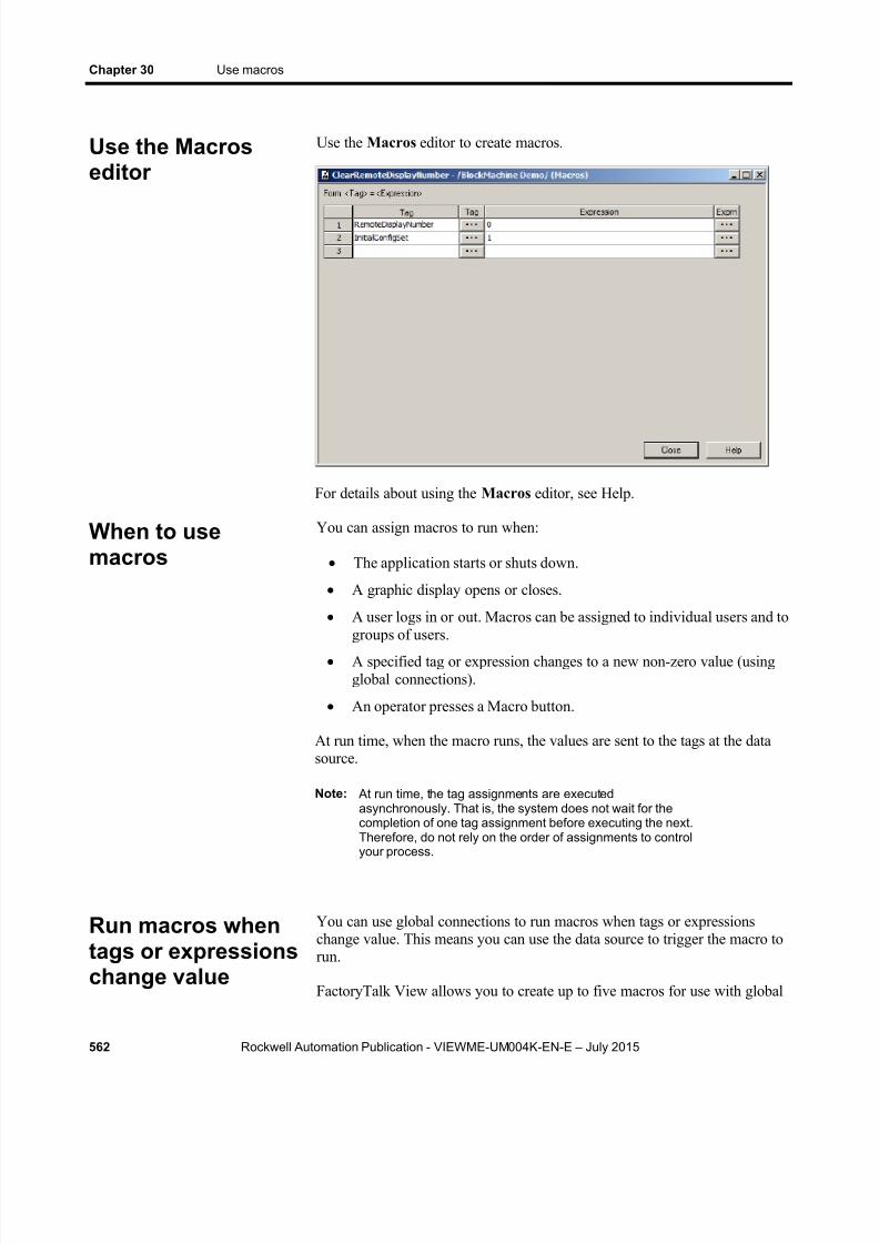
8/15/2019 Factory Talk View ME
http://slidepdf.com/reader/full/factory-talk-view-me 562/635
Chapter 30 Use macros
562 Rockwell Automation Publication - VIEWME-UM004K-EN-E – July 2015
Use the Macros editor to create macros.
For details about using the Macros editor, see Help.
You can assign macros to run when:
The application starts or shuts down.
A graphic display opens or closes.
A user logs in or out. Macros can be assigned to individual users and to
groups of users. A specified tag or expression changes to a new non-zero value (using
global connections).
An operator presses a Macro button.
At run time, when the macro runs, the values are sent to the tags at the datasource.
Note: At run time, the tag assignments are executedasynchronously. That is, the system does not wait for thecompletion of one tag assignment before executing the next.Therefore, do not rely on the order of assignments to controlyour process.
You can use global connections to run macros when tags or expressionschange value. This means you can use the data source to trigger the macro torun.
FactoryTalk View allows you to create up to five macros for use with global
Use the Macroseditor
When to usemacros
Run macros whentags or expressionschange value
8/15/2019 Factory Talk View ME
http://slidepdf.com/reader/full/factory-talk-view-me 563/635
Use macros Chapter 30
Rockwell Automation Publication - VIEWME-UM004K-EN-E – July 2015 563
connections. The macros must be named Macro1, Macro2, Macro3, Macro4,and Macro5 in order to work with global connections.
For more information about global connections, see Set up global
connections on page 111 .
Example: Use macros to reset tag values
This example shows you how to run a macro whenever the operator needs toreset production information tags to known values.
The macro writes the desired values to the tags whenever the operator presses a Momentary push button.
1. Create a memory tag called ResetProdData .
2. Create a Momentary push button with the caption Reset Production Data . Assign the ResetProdData tag to the Value connection.
3. Create a macro called Macro1 , with these tag assignments:
TotalProductionUnits=0LineDownTime=0TotalRejects=0
4. In the Global Connections editor, assign the ResetProdData tag tothe Remote Macro1 connection.
When the operator presses the Reset Production Data button, the value ofthe ResetProdData tag changes from 0 to 1. This tells FactoryTalk View torun Macro1, which writes the specified values to the tags in the macro.
Once you have created the macros you want to use, assign the macros inthese editors:
In this editor Do this
Startup Assign application startup and shutdown macros.
Graphics Assign macros to run when displays open or close, using
the Display Settings dialog box.Runtime Security Assign macros to run when users log in and log out.
Macros that you assign to groups of users run each timeany member of the group logs in or logs out.
GlobalConnections
Specify the tags or expressions that will run the macrosnamed Macro1 to Macro5.
Where to assignmacros

8/15/2019 Factory Talk View ME
http://slidepdf.com/reader/full/factory-talk-view-me 564/635
Chapter 30 Use macros
564 Rockwell Automation Publication - VIEWME-UM004K-EN-E – July 2015

8/15/2019 Factory Talk View ME
http://slidepdf.com/reader/full/factory-talk-view-me 565/635
Rockwell Automation Publication - VIEWME-UM004K-EN-E – July 2015 565
A p p e n d i x A
Convert PanelBuilder 1400eapplications
This appendix describes:
Terms that are different in PanelBuilder 1400e and FactoryTalk View
Steps for converting PanelBuilder 1400e applications
Names of equivalent graphic objects in the two products
PanelBuilder 1400e graphic objects that are not supported inFactoryTalk View
PanelBuilder 1400e settings and controls that are not supported inFactoryTalk View
How communications are converted and which PanelBuilder 1400ecommunication protocols are not supported in FactoryTalk View
Convert PanelBuilder 1400e Remote I/O communications
PanelBuilder 1400e graphic object features that are not supported inFactoryTalk View, with information about how to achieve the sameresult when possible
Convert PanelBuilder 1400e expressions
PanelBuilder 1400e applications are applications you create usingPanelBuilder 1400e Configuration Software for Windows. For informationabout converting applications from PanelBuilder or PanelBuilder32, seeConvert PanelBuilder and PanelBuilder32 applications on page 581 .
Note: You can convert PanelView 1200 applications to PanelBuilder1400e applications, and then convert the PanelBuilder 1400eapplications to FactoryTalk View Machine Edition applications.
These terms are different in PanelBuilder 1400e and FactoryTalk View.
PanelBuilder 1400e term FactoryTalk View term
screen display, graphic display
Optional Keypad Write Expression Optional Expression
programmable controller data source
Terminology
8/15/2019 Factory Talk View ME
http://slidepdf.com/reader/full/factory-talk-view-me 566/635
Appendix A Convert PanelBuilder 1400e applications
566 Rockwell Automation Publication - VIEWME-UM004K-EN-E – July 2015
PanelBuilder 1400e term FactoryTalk View term
control connection
In FactoryTalk View, the data source can be memory or a device such as a programmable controller or an OPC server. FactoryTalk View writes valuesto and reads values from the data source. The data source is configured toexchange information (in the form of numeric or string values) betweenFactoryTalk View and the machine that your application is controlling. Thegeneral term data source is used unless specifically discussing a
programmable controller.
Follow these steps to convert PanelBuilder 1400e applications:
1. Prepare the application in PanelBuilder 1400e, and then convert theapplication file, as described in the next section.
2. Specify additional project settings, as described on About projectsettings on page 72 . For example, if you want the application to have a
border around its graphic displays, or to use a title bar, you can specifythese options in the Project Settings editor.
Note: We recommend that you use the Project Settings editor tochange the project window size, rather than using the Convertto new window size option in the Machine Edition ImportWizard.
3. If you use the Convert to new window size option in the MachineEdition Import Wizard, check the position of the graphic objects in
each display.
4. Set up communications and edit tags that don’t convert directly.
For more information, see Convert non-RIO communications on page587 .
5. Set up graphic object features that don’t convert directly.
For more information, see Unsupported graphic object features on page576 .
6. Check each expression you used in PanelBuilder 1400e.
For more information, see Convert expressions on page 578 .
7. If you are going to use a printer at run time, set it up for Ethernet orUSB printing. Adjust the printer settings on the PanelView Plus orPanelView Plus CE terminal.
For information about setting up printers on the terminal, see the PanelView Plus Terminals User Manual .
Steps for convertingPanelBuilder 1400eapplications

8/15/2019 Factory Talk View ME
http://slidepdf.com/reader/full/factory-talk-view-me 567/635
Convert PanelBuilder 1400e applications Appendix A
Rockwell Automation Publication - VIEWME-UM004K-EN-E – July 2015 567
Follow these steps to convert a PanelBuilder 1400e application file, with theextension .pvc, to an FactoryTalk View application file, with the extension.med. The original PanelBuilder 1400e application file is not modified by theconversion.
For information about converting RIO applications, see Convert RIOcommunications on page 574 .
Steps to take in PanelBuilder 1400e before youconvert the application
1. Delete the Pass-Through file assignment. FactoryTalk View Studiodoes not support pass-through file transfers.
2.
Make sure the block transfer file numbers are sequential without gaps.If necessary, renumber the block transfer file numbers so there are nomissing numbers. Tag addresses in the application will changeautomatically to match the new number.
3. Save the application.
You can convert the PanelBuilder 1400e application when you openFactoryTalk View Studio, or once FactoryTalk View Studio is already open.
To convert a PanelBuilder 1400e application when
you open FactoryTalk View Studio1. Open FactoryTalk View Studio.
2. In the New tab, in the Application name box, type a name for yourconverted application, up to 32 characters long.
3. If desired, type a description of the application.
If the PanelBuilder 1400e application contains an Application FileComment, the Application File Comment will overwrite thedescription you type here. You can add or change the description later,as described on View application properties on page 77 .
4. Specify a language for the converted application. For informationabout using different languages, see Set up language switching on page197 .
ConvertPanelBuilder 1400eapplication files
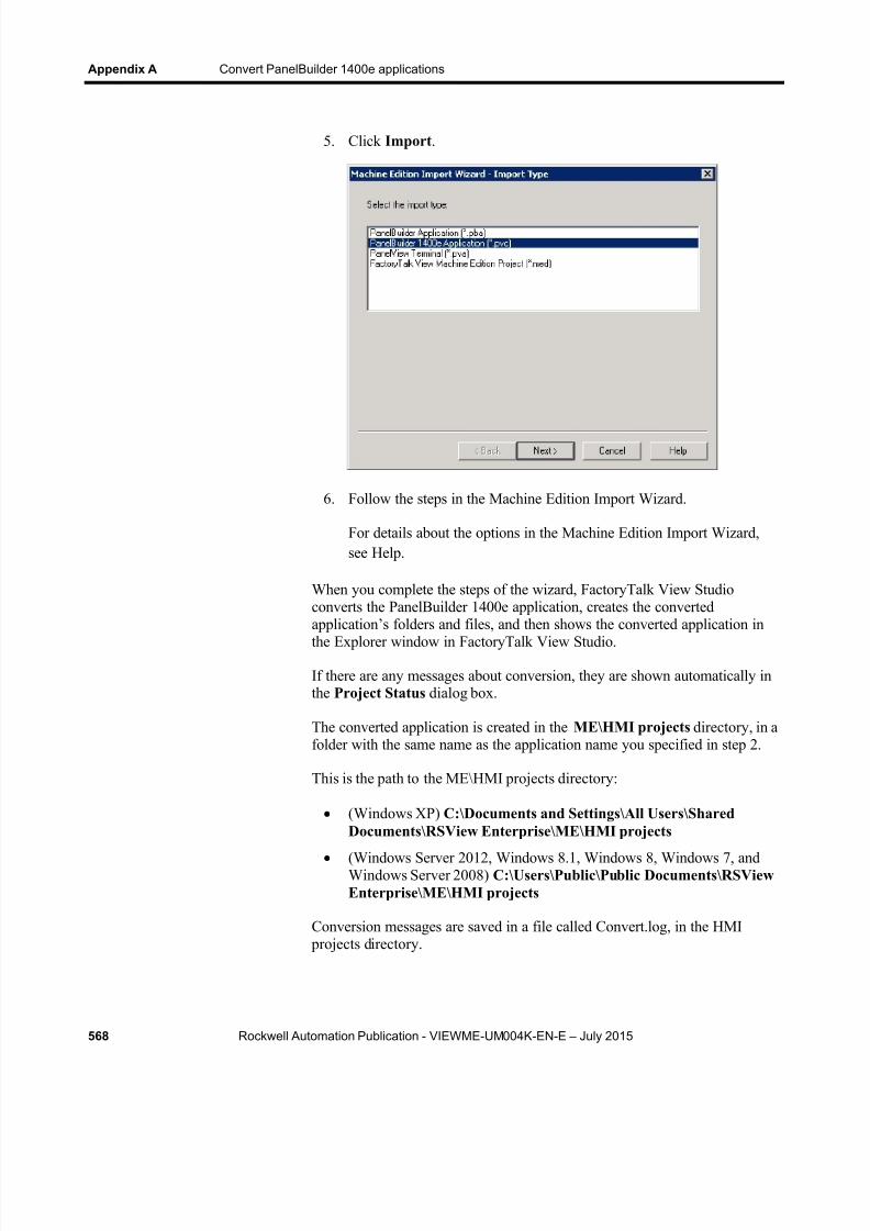
8/15/2019 Factory Talk View ME
http://slidepdf.com/reader/full/factory-talk-view-me 568/635
Appendix A Convert PanelBuilder 1400e applications
568 Rockwell Automation Publication - VIEWME-UM004K-EN-E – July 2015
5. Click Import .
6. Follow the steps in the Machine Edition Import Wizard.
For details about the options in the Machine Edition Import Wizard,see Help.
When you complete the steps of the wizard, FactoryTalk View Studioconverts the PanelBuilder 1400e application, creates the converted
application’s folders and files, and then shows the converted application inthe Explorer window in FactoryTalk View Studio.
If there are any messages about conversion, they are shown automatically inthe Project Status dialog box.
The converted application is created in the ME\HMI projects directory, in afolder with the same name as the application name you specified in step 2.
This is the path to the ME\HMI projects directory:
(Windows XP) C:\Documents and Settings\All Users\SharedDocuments\RSView Enterprise\ME\HMI projects
(Windows Server 2012, Windows 8.1, Windows 8, Windows 7, andWindows Server 2008) C:\Users\Public\Public Documents\RSViewEnterprise\ME\HMI projects
Conversion messages are saved in a file called Convert.log, in the HMI projects directory.

8/15/2019 Factory Talk View ME
http://slidepdf.com/reader/full/factory-talk-view-me 569/635
Convert PanelBuilder 1400e applications Appendix A
Rockwell Automation Publication - VIEWME-UM004K-EN-E – July 2015 569
To convert a PanelBuilder 1400e application whenFactoryTalk View Studio is already open
1. From the File menu, select New Application , or click the New
Application tool .
If an application is already open, FactoryTalk View Studio asks youwhether to close the application that is currently open. Click Yes .
2. Follow steps 2 through 7 in the previous procedure.
This section describes graphic objects that are equivalent in PanelBuilder1400e and FactoryTalk View, but have different names in the two products.
This PanelBuilder 1400eobject
Is converted to thisFactoryTalk Viewobject Notes
Increment Value Button Ramp button During conversion the button isset up to increment.
Decrement Value Button Ramp button During conversion the button isset up to decrement.
Increment Value Buttonwith Display
Ramp button andnumeric display
The Increment Value Button withDisplay is divided into twoseparate FactoryTalk Viewobjects.
Decrement Value Buttonwith Display
Ramp button andnumeric display
The Decrement Value Buttonwith Display is divided into twoseparate FactoryTalk Viewobjects.
ASCII Input (small andlarge)
String Input Enablebutton
Numeric Entry Keypad(small and large)
Numeric input enablebutton
Screen List Selector’s list Display list selector The PanelBuilder 1400e ScreenList Selector is divided into fourseparate FactoryTalk Viewgraphic objects.
Screen List Selector’sEnter Key
Enter button
Screen List Selector’sDown Cursor
Move down button
Screen List Selector’s UpCursor
Move up button
Control List Selector’s list Control list selector The PanelBuilder 1400e ControlList Selector is divided into fourseparate FactoryTalk Viewgraphic objects.
Control List Selector’sEnter Key
Enter button
Equivalent graphicobjects

8/15/2019 Factory Talk View ME
http://slidepdf.com/reader/full/factory-talk-view-me 570/635
Appendix A Convert PanelBuilder 1400e applications
570 Rockwell Automation Publication - VIEWME-UM004K-EN-E – July 2015
This PanelBuilder 1400eobject
Is converted to thisFactoryTalk Viewobject Notes
Control List Selector’s
Down Cursor
Move down button
Control List Selector’s UpCursor
Move up button
Screen Select Keypad(small and large)
Display list selector Specify the graphic displays thatthe display list selector can open.
Screen Keypad EnableButton
Display list selector Specify the graphic displays thatthe display list selector can open.
Goto Screen Button Goto display button
Return to Previous ScreenButton
Return to displaybutton
ASCII Display String display
Numeric Keypad EnableButton Numeric input enablebutton
Normally OpenMomentary Push Button
Momentary pushbutton
During conversion the button isset up to be normally open.
Normally ClosedMomentary Push Button
Momentary pushbutton
During conversion the button isset up to be normally closed.
Screen Print Button Display print button
Alarm History Sort ByTime/Sort By Value Button
Sort alarms button
Alarm Status ResetQty/Time Button
Reset alarm statusbutton
Alarm Panel Alarm banner
Single Line Alarm Window Alarm banner
Alarm Status Screen Alarm status list
Clear All Button Clear alarm historybutton
Print Button (in AlarmHistory screen)
Print alarm historybutton
Print Button (in AlarmStatus screen)
Print alarm statusbutton
Alarm Status Button/AlarmHistory Button
Goto display button
Exit Button Close display button
Alarm History List Alarm list
Display Mode Button Alarm status modebutton

8/15/2019 Factory Talk View ME
http://slidepdf.com/reader/full/factory-talk-view-me 571/635
Convert PanelBuilder 1400e applications Appendix A
Rockwell Automation Publication - VIEWME-UM004K-EN-E – July 2015 571
This PanelBuilder 1400eobject
Is converted to thisFactoryTalk Viewobject Notes
Time Display Time and date display During conversion the display is
set up to show the time only. ThePanelBuilder 1400e time formatis not converted. For detailsabout the FactoryTalk View timeformat, see Time, date, andnumber formats for graphicobjects on page 403 .
Date Display Time and date display During conversion the display isset up to show the date only. ThePanelBuilder 1400e date formatis not converted. For detailsabout the FactoryTalk View dateformat, see Time, date, andnumber formats for graphicobjects on page 403 .
Arc (with solid fill style) Arc (with solid backstyle) and line
The line graphic object is addedbecause the solid FactoryTalkView arc shape does not have aline between the two points ofthe arc.
These PanelBuilder 1400e objects are not supported in FactoryTalk View:
Scrolling List (includes Cursor List, Multistate Indicator Object List,Local Message Object List, Numeric Data Display Object List)
Set Bit Cursor Point
This section describes PanelBuilder 1400e settings and controls that are notused in FactoryTalk View.
Controls for transferring runtime application files
PanelBuilder 1400e uses these optional controls for transferring files to theruntime terminal:
Transfer Inhibit control
Transfer Request control
Transfer Status control
Unsupportedgraphic objects
Unsupportedsettings andcontrols
8/15/2019 Factory Talk View ME
http://slidepdf.com/reader/full/factory-talk-view-me 572/635
Appendix A Convert PanelBuilder 1400e applications
572 Rockwell Automation Publication - VIEWME-UM004K-EN-E – July 2015
These controls are not necessary in FactoryTalk View because the METransfer Utility allows you to transfer the runtime project file while runninga project on the runtime terminal.
Settings and controls for alarms
FactoryTalk View does not use these PanelBuilder 1400e features andsettings to manage alarms:
Alarm relays
Bit alarm acknowledgement
Remote Alarm Operation Hold Time. The PanelBuilder 1400e RemoteAlarm Ack Control Hold Time will be used for all alarm hold times.You can change the hold time in the FactoryTalk View Alarm Setup editor, in the Advanced tab.
Remote Alarm Control Delay Time. In FactoryTalk View, if an Ackconnection is assigned, when an alarm is acknowledged the Ackconnection is set immediately, without waiting for a delay time.
FactoryTalk View does not use these PanelBuilder 1400e controls to managealarms:
PLC Controlled Relay control
PLC Controlled Audio control
Acknowledge to PLC control (if the Alarm Acknowledge to PLCoption is set to Bit)
Invalid characters in screen names
Characters in PanelBuilder 1400e screen names that are not supported inFactoryTalk View are replaced with the underscore character.
Screen security settings
PanelBuilder 1400e screen security settings are not converted, becauseFactoryTalk View uses a different method to assign security to graphicdisplays. For information about setting up security in FactoryTalk View, seeSet up security on page 175 .

8/15/2019 Factory Talk View ME
http://slidepdf.com/reader/full/factory-talk-view-me 573/635
Convert PanelBuilder 1400e applications Appendix A
Rockwell Automation Publication - VIEWME-UM004K-EN-E – July 2015 573
Block tags
Block tags are not supported in FactoryTalk View. Block tags that aremonitored for alarms in your PanelBuilder 1400e application are convertedto bit arrays. For information about monitoring bit arrays for alarmconditions, see Set up alarms on page 119 .
This section describes how communications that do not useRemote I/O (RIO) are converted.
FactoryTalk View does not use nodes for communications. Nodes areconverted to RSLinx topics. Topics are then converted into device shortcuts,to run with RSLinx Enterprise. You must have both RSLinx Classic andRSLinx Enterprise installed to make this two-step conversion.
Tags are converted to HMI device tags and RSLinx aliases. The
Unsolicited_Msgs node is not converted.
If you import an application multiple times, delete the device shortcuts inRSLinx Enterprise before re-importing. Otherwise, multiple unused deviceshortcuts will be created in RSLinx Enterprise.
For more information about setting up communications, see Set upcommunications on page 79 .
For information about converting RIO communications, see Convert RIOcommunications on page 574 .
Unsupported tag data types
These tag data types are not supported in FactoryTalk View:
Bit Position
1-BCD, 2-BCD, 5-BCD, 6-BCD, 7-BCD, 8-BCD
BIN3, BIN4, BIN6, BIN8 (used with Modbus communications)
Tags that use these data types are converted to analog HMI tags with theDefault data type. The Default data type uses floating point values.
For Bit Position data types, use the bitwise expression operators to showdata that does not reference supported lengths. For more information, see theRockwell Automation KnowledgeBase.
To open the Know ledgeBase
In FactoryTalk View Studio, on the Help menu, select RockwellSoftware on the Web, and then click Rockwell AutomationKnowledgeBase .
Convert non-RIOcommunications
8/15/2019 Factory Talk View ME
http://slidepdf.com/reader/full/factory-talk-view-me 574/635
Appendix A Convert PanelBuilder 1400e applications
574 Rockwell Automation Publication - VIEWME-UM004K-EN-E – July 2015
For information about using bitwise expression operators, see Bitwiseoperators on page 482 .
Unsupported initial values
Device tags in FactoryTalk View do not use initial values. Memory tags areconverted with their initial values.
You can use Remote I/O (RIO) communications on the PanelView Plus, andPanelView Plus CE runtime platforms.
Note: For PanelView Plus 7 and PanelView Plus 6 terminals, youneed a third party RIO to Ethernet gateway module for RIOcommunications. For more information, see Answer ID 490889in Rockwell Automation Knowledgebase.
RIO communications are not supported for the applications that run on a personal computer. However, you can test run your RIO applications on thedevelopment computer.
To convert an RIO application from PanelBuilder1400e to FactoryTalk View
1. Convert the application.
For more information, see Convert PanelBuilder 1400e applicationfiles on page 567 .
2. Open the RSLinx Enterprise data server, and then double-clickCommunication Setup .
3. In the Communication Setup editor, add an RIO driver.
For PanelView Plus 400 and 600 terminals, use the 2711P-RN1driver.
For all other PanelView Plus or PanelView Plus CE terminals, usethe 2711P-RN6 driver.
For information about adding drivers in RSLinx, see RSLinx Help.
4. Expand the RIO tree, right-click RIO Data, and then click ConfigureRIO .
5. In the RIO Configuration dialog box, right-click RIO, and then clickImport .
6. Browse to the location of the RIO configuration file.
Convert RIOcommunications

8/15/2019 Factory Talk View ME
http://slidepdf.com/reader/full/factory-talk-view-me 575/635
Convert PanelBuilder 1400e applications Appendix A
Rockwell Automation Publication - VIEWME-UM004K-EN-E – July 2015 575
The file is saved in the root of the application’s directory.
7. In the Communications Setup editor, create a device shortcut that points to the RIO data device.
For information about creating a device shortcut, see RSLinx Help.
8. Apply the shortcut to the RIO driver.
9. Correct any invalid RIO configurations. Invalid RIO configurations arehighlighted with red "x" icons.
Note: If red "x" icons appear after you import the RIO .xml file, youcan fix block tags in the Communication Setup editor inFactoryTalk View. The length of block tags must be the samefor Read and Write pairs sharing the same rack, group, andslot.
10. Create an alias for any data that is not a 16-bit integer or bit.
11. Save the converted RIO application.
Important: RIO configurations are not saved with theapplication when you exit FactoryTalk View Studio.However, they are backed up with the applicationin the Application Manager.For information about handling multipleapplications with different RIO settings, see theRockwell Automation KnowledgeBase.For information about using the ApplicationManager, see Rename, copy, delete, back up, andrestore applications on page 71 .
A PanelBuilder 1400e RIO tag will be converted to an HMI memory tag andan error will be logged to the conversion log file if the RIO tag:
Has a blank address.
Has a data type of 1-BCD, 2-BCD, 3-BCD, 5-BCD, 6-BCD, or7-BCD.
Has a data type of Bit Position and its address does not reference asingle bit.
Float has a data type of Float and its address has a bit offset assignedthat is not 0.
Has a data type of Long Integer or 8 Digit BCD, its address has a bitoffset assigned that is not 0, and its length or range is greater than (32 -Start Bit ).
Has a tag type of Block.
UnsupportedPanelBuilder 1400eRIO tags
8/15/2019 Factory Talk View ME
http://slidepdf.com/reader/full/factory-talk-view-me 576/635
Appendix A Convert PanelBuilder 1400e applications
576 Rockwell Automation Publication - VIEWME-UM004K-EN-E – July 2015
Has an invalid PanelBuilder 1400e address or references an undefinedrack.
This section describes features of PanelBuilder 1400e graphic objects that
are not supported in FactoryTalk View. The Notes column providesadditional information and describes methods for achieving the same resultwhen possible.
Graphic objectUnsupported feature inFactoryTalk View Notes
Image text, arc,ellipse, line, panel,rectangle, wedge
Blinking wallpaper objects If you want an object to blink at run time,unlock the wallpaper.In FactoryTalk View, all of the listedobjects except images use coloranimation to blink. For details, see Set upcolor animation on page 465 .
Color images do not blink. Monochromeimages use the Blink property to blink.
Numeric Display Polarity If a PanelBuilder 1400e application wasset up with the Polarity control requiring anegative number to show the minus sign,the numeric display will not work properlyafter the application is converted toFactoryTalk View Machine Edition.
Numeric Input CursorPoint, Numeric DataDisplay
Fixed Position and PLCControlled decimal displayoptions
Use an expression to achieve the sameresult. Assign the expression to theobject’s Value connection. For informationabout expressions, see Use expressions on page 475 .
Numeric Input CursorPoint, NumericKeypad EnableButton, NumericKeypad
PLC Controlled andDecimal Key Controlled input options
Objects are converted with the DecimalPoint property set to Implicit .
Numeric Input CursorPoint
Retain Cursor on Cancel The numeric input cursor point retainsfocus when the operator cancels enteringa numeric value.
Maintained pushButton, MultistatePush Button, ControlList Selector
Initial state values If you want to set these objects’ states onapplication startup, create a macro to setthe appropriate tag values for the objects’connections. For information aboutmacros, see Use macros on page 561 .
Assign the macro in the Startup editor.
For details, see Help.
Unsupportedgraphic objectfeatures
8/15/2019 Factory Talk View ME
http://slidepdf.com/reader/full/factory-talk-view-me 577/635
8/15/2019 Factory Talk View ME
http://slidepdf.com/reader/full/factory-talk-view-me 578/635
Appendix A Convert PanelBuilder 1400e applications
578 Rockwell Automation Publication - VIEWME-UM004K-EN-E – July 2015
Some PanelBuilder 1400e expression syntax is not supported in FactoryTalkView. Expressions are converted without modification, and then turned off
by placing warning text at the beginning of the first line of the expression. Inaddition, exclamation marks (!) are placed at the beginning of each
subsequent line of the expression. Warming text is also placed in expressionsassigned to alarm triggers in the Alarm Setup editor. To turn on theexpression, you must remove the warning text and exclamation marks, andrevise the syntax if necessary.
The maximum expression length in FactoryTalk View is 16,000 characters.If a PanelBuilder 1400e expression contains more than 16,000 characters, theexcess characters are not converted.
Some PanelBuilder 1400e objects support both tags and expressions. Forthese objects, if the text assigned to a connection could be valid syntax for
both a tag and an expression, the connection is treated as an expression, and
is therefore turned off.
For example, N20-0_String_64 could be the name of a tag, or it could be anexpression that subtracts "0_String_64" from the tag "N20." The text would
be converted as an expression, and turned off.
To turn on an expression
1. Select the object containing the expression.
2. Open the Property Panel , and then click the Connections tab.
3. In the Exprn column, click the Browse button beside the expression toturn on.
4. In the Expression editor, delete the warning text and exclamationmarks.
5. Revise the expression, if necessary, using the tables in the followingthree sections as guides.
6. Click Check Syntax .
For more information about using the Expression editor, see Use expressions on page 475 or Help.
Equivalent expression syntax
This table describes FactoryTalk View expression syntax that is equivalent toPanelBuilder 1400e syntax. When you edit the converted expressions,replace the PanelBuilder 1400e syntax with the FactoryTalk Viewequivalent.
Convertexpressions

8/15/2019 Factory Talk View ME
http://slidepdf.com/reader/full/factory-talk-view-me 579/635
Convert PanelBuilder 1400e applications Appendix A
Rockwell Automation Publication - VIEWME-UM004K-EN-E – July 2015 579
Syntax that is not listed in this table or in the next section is okay the way itis.
Type of expressioncomponent or operator
PanelBuilder 1400esyntax
FactoryTalk Viewsyntax
Comment REM or ‘ !
Line continuation _ (underscore) Not needed.
Equality ( = ) EQ or ==
Bitwise NotBitwise AndBitwise OrBitwise XOrIf both operands are Byte,Integer, Long, Variant, or anycombination of these datatypes, use the FactoryTalkView syntax. For other datatypes, no change is needed.
Not AndOrXOr
~ (tilde)&| (pipe)^
Unsupported expression syntax
This table describes the PanelBuilder 1400e expression syntax that is notsupported in FactoryTalk View with information about how to achieve thesame result where possible.
Type of expressioncomponent or operator
PanelBuilder 1400esyntax
Equivalent FactoryTalkView syntax (if any)
Exit statement Exit
Local variables DIM varname AS ...varname =
Integer division \ ( x - ( x MOD y ))/y
Endif If then endifIf then else endif
If then else 0If then else
Select case Select CaseCase1...CaseN
CaseElseEndSelect
Use nested if-then-else.
Logical Xor (if one or bothoperands are Boolean orSingle data types)
Xor NOT (( x AND y )OR NOT ( x OR y ))

8/15/2019 Factory Talk View ME
http://slidepdf.com/reader/full/factory-talk-view-me 580/635
Appendix A Convert PanelBuilder 1400e applications
580 Rockwell Automation Publication - VIEWME-UM004K-EN-E – July 2015
Order of precedence
The order of precedence is slightly different in FactoryTalk View. Checkyour expressions to make sure the result is what you intend.
PanelBuilder 1400eorder of precedence FactoryTalk View order of precedence
( ) ( )
- (negation) NOT, ~ (tilde)
*, / (floating point division) *, /, MOD, %, **, AND, &&, &, >>, <<
\ (integer division) +, -, OR, ||, |, ^
MOD EQ, ==, NE, <>, LT, <, GT, >, LE, <=, GE, >=
+, - (subtraction)
=, <>, <, >, <=, >=
Not
And
Or
Xor
For more information about order of precedence, see Evaluation order ofoperators on page 484 .
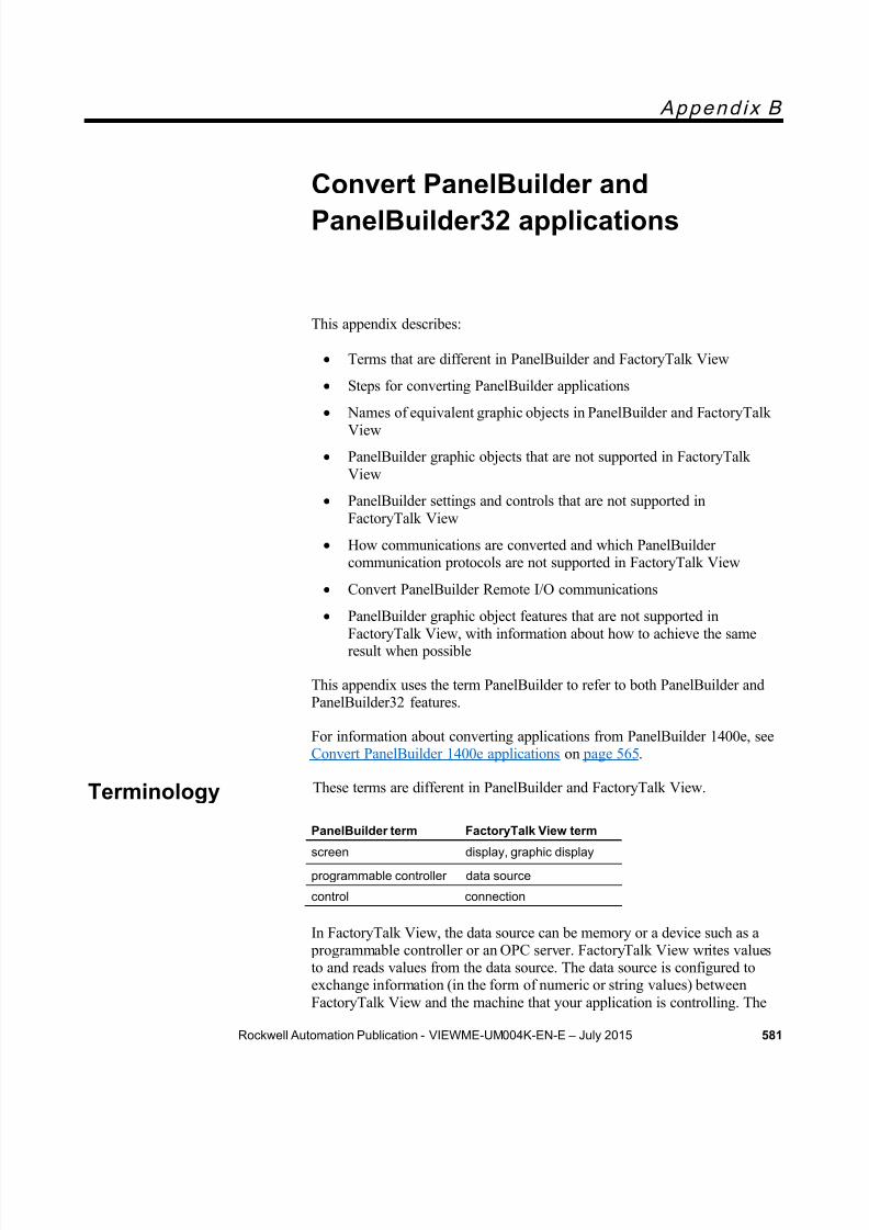
8/15/2019 Factory Talk View ME
http://slidepdf.com/reader/full/factory-talk-view-me 581/635
Rockwell Automation Publication - VIEWME-UM004K-EN-E – July 2015 581
A p p e n d i x B
Convert PanelBuilder andPanelBuilder32 applications
This appendix describes:
Terms that are different in PanelBuilder and FactoryTalk View
Steps for converting PanelBuilder applications
Names of equivalent graphic objects in PanelBuilder and FactoryTalkView
PanelBuilder graphic objects that are not supported in FactoryTalkView
PanelBuilder settings and controls that are not supported inFactoryTalk View
How communications are converted and which PanelBuildercommunication protocols are not supported in FactoryTalk View
Convert PanelBuilder Remote I/O communications
PanelBuilder graphic object features that are not supported inFactoryTalk View, with information about how to achieve the sameresult when possible
This appendix uses the term PanelBuilder to refer to both PanelBuilder andPanelBuilder32 features.
For information about converting applications from PanelBuilder 1400e, seeConvert PanelBuilder 1400e applications on page 565 .
These terms are different in PanelBuilder and FactoryTalk View.
PanelBuilder term FactoryTalk View term
screen display, graphic display
programmable controller data source
control connection
In FactoryTalk View, the data source can be memory or a device such as a programmable controller or an OPC server. FactoryTalk View writes valuesto and reads values from the data source. The data source is configured toexchange information (in the form of numeric or string values) betweenFactoryTalk View and the machine that your application is controlling. The
Terminology

8/15/2019 Factory Talk View ME
http://slidepdf.com/reader/full/factory-talk-view-me 582/635
Appendix B Convert PanelBuilder and PanelBuilder32 applications
582 Rockwell Automation Publication - VIEWME-UM004K-EN-E – July 2015
general term data source is used unless specifically discussing a programmable controller.
Follow these steps to convert PanelBuilder applications:
1. Convert the application file, as described in the next section.
2. Specify additional project settings, as described on About projectsettings on page 72 . For example, if you want the application to have a
border around its graphic displays, or to use a title bar, you can specifythese options in the Project Settings editor.
3. If you select Convert to new window size , check the position of thegraphic objects in each display.
4. Set up communications and edit tags that don’t convert directly.
For more information, see Convert non-RIO communications on page587 .
5. Set up gra phic object features that don’t convert directly.
For more information, see Unsupported graphic object features on page590 .
Follow these steps to convert a PanelBuilder application file, with theextension .pba or .pva, to an FactoryTalk View application file, with theextension .med. The original PanelBuilder application file is not modified by
the conversion.
Steps to take in PanelBuilder before you convertthe application
1. Semicolons (;) in tag addresses are supported in PanelBuilder, but notin FactoryTalk View Studio. Before importing the PanelBuilderapplication, in the PanelBuilder Tag Editor, change the semicolons tocolons (:).
2. Dashes (-) in tag names are supported in PanelBuilder, but not inFactoryTalk View Studio. Before importing the PanelBuilderapplication, in the PanelBuilder Tag Editor, locate any tags whosenames contain dashes and duplicate the tags. Then rename the tagswithout the dash, or replace the dash with an underscore (_). Once thetags have been renamed, use the Tag Search feature to find the graphicobjects using the original tag names and edit the objects to replace theold tag names with the new ones.
You can convert the PanelBuilder application when you open FactoryTalkView Studio, or once FactoryTalk View Studio is already open.
Steps for convertingPanelBuilderapplications
ConvertPanelBuilder
application files
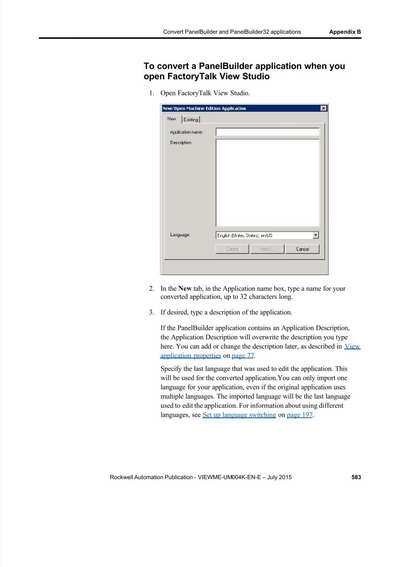
8/15/2019 Factory Talk View ME
http://slidepdf.com/reader/full/factory-talk-view-me 583/635
Convert PanelBuilder and PanelBuilder32 applications Appendix B
Rockwell Automation Publication - VIEWME-UM004K-EN-E – July 2015 583
To convert a PanelBuilder application when youopen FactoryTalk View Studio
1. Open FactoryTalk View Studio.
2. In the New tab, in the Application name box, type a name for yourconverted application, up to 32 characters long.
3. If desired, type a description of the application.
If the PanelBuilder application contains an Application Description,the Application Description will overwrite the description you typehere. You can add or change the description later, as described in Viewapplication properties on page 77 .
Specify the last language that was used to edit the application. Thiswill be used for the converted application.You can only import one
language for your application, even if the original application usesmultiple languages. The imported language will be the last languageused to edit the application. For information about using differentlanguages, see Set up language switching on page 197 .
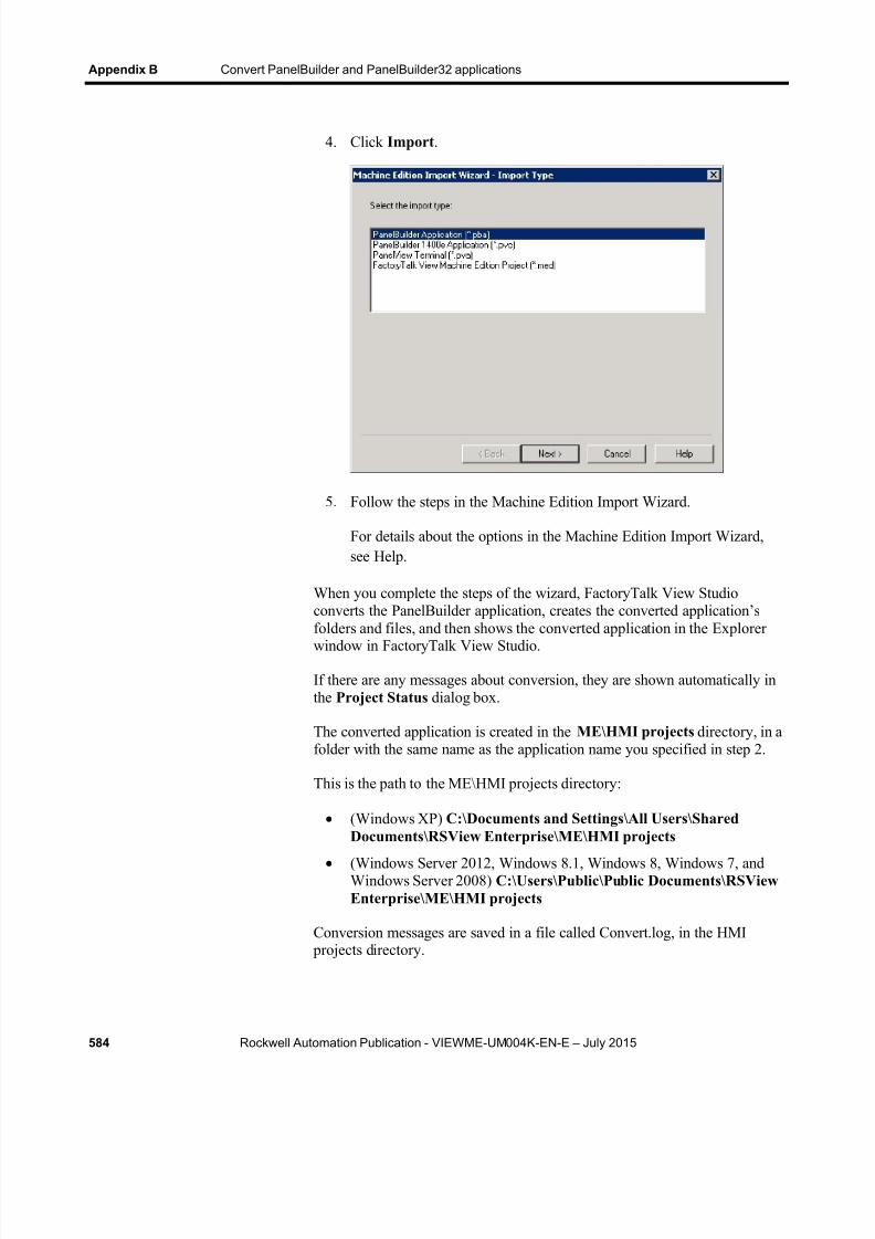
8/15/2019 Factory Talk View ME
http://slidepdf.com/reader/full/factory-talk-view-me 584/635
Appendix B Convert PanelBuilder and PanelBuilder32 applications
584 Rockwell Automation Publication - VIEWME-UM004K-EN-E – July 2015
4. Click Import .
5. Follow the steps in the Machine Edition Import Wizard.
For details about the options in the Machine Edition Import Wizard,see Help.
When you complete the steps of the wizard, FactoryTalk View Studioconverts the PanelBuilder application, creates the converted application’s
folders and files, and then shows the converted application in the Explorerwindow in FactoryTalk View Studio.
If there are any messages about conversion, they are shown automatically inthe Project Status dialog box.
The converted application is created in the ME\HMI projects directory, in afolder with the same name as the application name you specified in step 2.
This is the path to the ME\HMI projects directory:
(Windows XP) C:\Documents and Settings\All Users\SharedDocuments\RSView Enterprise\ME\HMI projects
(Windows Server 2012, Windows 8.1, Windows 8, Windows 7, andWindows Server 2008) C:\Users\Public\Public Documents\RSViewEnterprise\ME\HMI projects
Conversion messages are saved in a file called Convert.log, in the HMI projects directory.

8/15/2019 Factory Talk View ME
http://slidepdf.com/reader/full/factory-talk-view-me 585/635
Convert PanelBuilder and PanelBuilder32 applications Appendix B
Rockwell Automation Publication - VIEWME-UM004K-EN-E – July 2015 585
To convert a PanelBuilder application whenFactoryTalk View Studio is already open
1. From the File menu, select New Application , or click the New
Application tool .
If an application is already open, FactoryTalk View Studio asks youwhether to close the application that is currently open. Click Yes .
2. Follow steps 2 through 7 in the previous procedure.
This section describes graphic objects that are equivalent in PanelBuilderand FactoryTalk View, but have different names in the two products.
This PanelBuilderobject
Is converted to thisFactoryTalk View object Notes
Numeric Entry KeypadEnable Button
Numeric input enable button
Numeric Entry CursorPoint
Numeric input enable button
Increment/DecrementEntry Button
Numeric input enable button The Numeric Input Enable buttonis set up to work as a Ramp
button, using the Fine Stepvalue. The Coarse Step value isnot converted.
ASCII Entry KeypadEnable button
String Input Enable button The Show Current String on ASCII Scratchpad setting is notconverted. The pop-upscratchpad or keyboard is alwaysblank when opened.
ASCII Entry CursorPoint
String Input Enable button The Show Current String on ASCII Scratchpad setting is notconverted. The pop-upscratchpad or keyboard is alwaysblank when opened.
Message Display Multistate indicator
Numeric Data Display Text The text object contains anumeric embedded variable thatshows the read tag.If the original numeric datadisplay object does not containtext, manually create a numericdisplay object with the desiredproperties in FactoryTalk View.
Connected Line Polyline
Circle Ellipse The ellipse has a circular shape.
Equivalent graphicobjects

8/15/2019 Factory Talk View ME
http://slidepdf.com/reader/full/factory-talk-view-me 586/635
Appendix B Convert PanelBuilder and PanelBuilder32 applications
586 Rockwell Automation Publication - VIEWME-UM004K-EN-E – July 2015
This PanelBuilderobject
Is converted to thisFactoryTalk View object Notes
Freeform Freehand
Screen List Selector Display list selectorGoto Screen Button Goto display button
Return Screen Button Return to display button
New Password Button Password button
Print Alarm List Button Print alarm history button
Clear Alarm List Button Clear alarm history button
These PanelBuilder objects are not supported in FactoryTalk View:
Print Only Object
Circular Scale
Scrolling Text
Print Alarm Button
Horn Silence Button
Lamp/Horn Test Button
Select Operator Button
Enable/Disable Security Button
Verify Password Button. The FactoryTalk View Password button
opens a dialog box that allows the user to type and verify a new password.
This section describes PanelBuilder settings and controls that are not used inFactoryTalk View.
Settings and controls for alarms
FactoryTalk View does not use these PanelBuilder features and settings tomanage alarms:
Ack setting for alarm messages - in FactoryTalk View, all alarms can be acknowledged
Bit alarm acknowledgement
FactoryTalk View does not use these PanelBuilder controls to managealarms:
Remote Ack All Handshake Tag
Remote Clear All Alarm Tag
Unsupportedgraphic objects
Unsupportedsettings andcontrols

8/15/2019 Factory Talk View ME
http://slidepdf.com/reader/full/factory-talk-view-me 587/635
Convert PanelBuilder and PanelBuilder32 applications Appendix B
Rockwell Automation Publication - VIEWME-UM004K-EN-E – July 2015 587
Remote Clear All Alarm Handshake Tag
Invalid characters in screen names and tag namesCharacters in PanelBuilder screen names and tag names that are notsupported in FactoryTalk View are replaced with the underscore character.
Time and date
PanelBuilder time and date formats are not converted. For details aboutFactoryTalk View time and date formats, see Time, date, and numberformats for graphic objects on page 403 .
External fonts
PanelBuilder external fonts are not converted. When you convert yourapplication you can specify the font to use instead. For details, see Help forthe Machine Edition Import Wizard.
Screen security settings
PanelBuilder screen security settings are not converted, because FactoryTalk
View uses a different method to assign security to graphic displays. Forinformation about setting up security in FactoryTalk View, see Set upsecurity on page 175 .
Power-up options
These PanelBuilder power-up options are not imported into FactoryTalkView:
Write Last Terminal State to Controller
Display Last User Screen Use Terminal Presets
This section describes how communications that do not useRemote I/O (RIO) are converted.
FactoryTalk View does not use nodes for communications. Nodes areconverted to RSLinx topics. Topics are then converted into device shortcuts,to run with RSLinx Enterprise. You must have both RSLinx Classic andRSLinx Enterprise installed to make this two-step conversion.
Convert non-RIOcommunications
8/15/2019 Factory Talk View ME
http://slidepdf.com/reader/full/factory-talk-view-me 588/635
Appendix B Convert PanelBuilder and PanelBuilder32 applications
588 Rockwell Automation Publication - VIEWME-UM004K-EN-E – July 2015
Tags are converted to HMI device tags and RSLinx aliases. TheUnsolicited_Msgs node is not converted.
If you import an application multiple times, delete the device shortcuts in
RSLinx Enterprise before re-importing. Otherwise, multiple unused deviceshortcuts will be created in RSLinx Enterprise.
For more information about setting up communications, see Set upcommunications on page 79 .
For information about converting RIO communications, see Convert RIOcommunications on page 574 .
Tags for unsupported communication protocols
Some communication protocols are not supported in FactoryTalk View. Forexample, DH+ communications that use the AutoMax node type are notsupported. FactoryTalk View does not support CIP and Assembly Objectaddressing (used in PanelBuilder32 Ethernet communications).
Tags that use unsupported communication protocols are converted to HMImemory tags. Once you have set up communications for your convertedapplication, change the memory tags to device tags that point to the correctaddresses. All other imported tags are converted to HMI device tags.
For information about editing HMI tags, see Use HMI tags on page 97 . Formore information about which communication protocols are not supported,
see Help or see the Rockwell Automation Knowledgebase.
Bit array tags
You can monitor bit arrays for alarm conditions in FactoryTalk View, butyou can’t assign b it arrays to most graphic objects or write to bit arrays. (Theonly exception is the piloted control list selector object. For this object, youcan assign a bit array tag to the Visible States connection.)
All bit array tags in your PanelBuilder application are converted to HMImemory tags.
For information about monitoring bit arrays for alarm conditions, see Set upalarms on page 119 . For information about editing HMI tags, see Use HMItags on page 97 . For information about the piloted control list selector, seeHelp.
Remote I/O (RIO) communications are not supported for applications thatwill run on personal computers. You can use RIO communications on thePanelView Plus and PanelView Plus CE runtime platforms.
Convert RIOcommunications

8/15/2019 Factory Talk View ME
http://slidepdf.com/reader/full/factory-talk-view-me 589/635
Convert PanelBuilder and PanelBuilder32 applications Appendix B
Rockwell Automation Publication - VIEWME-UM004K-EN-E – July 2015 589
Supported PanelBuilder tags are converted to HMI device tags and RSLinxaliases. For information about unsupported PanelBuilder tags, see below.
To convert an RIO application from PanelBuilder toFactoryTalk View
1. Convert the application, as described on Convert PanelBuilderapplication files on page 582 .
2. Open the RSLinx Enterprise data server, and then double-clickCommunication Setup .
3. In the Communication Setup editor, add an RIO driver.
For PanelView Plus 400 and 600 terminals, use the 2711P-RN1driver.
For all other PanelView Plus or PanelView Plus CE terminals, usethe 2711P-RN6 driver.
For information about adding drivers in RSLinx, see RSLinx Help.
4. Expand the RIO tree, right-click RIO Data, and then click ConfigureRIO .
5. In the RIO Configuration dialog box, right-click RIO, and then clickImport .
6. Browse to the location of the RIO configuration file.
The file is saved in the root of the application’s directory.
7. In the Communications Setup editor, create a device shortcut that points to the RIO data device.
For information about creating a device shortcut, see RSLinx Help.
8. Apply the shortcut to the RIO driver.
9. Correct any invalid RIO configurations. Invalid RIO configurations arehighlighted with red "x" icons.
Note: If red "x" icons appear after you import the RIO .xml file, youcan fix block tags in the Communication Setup editor inFactoryTalk View. The length of block tags must be the samefor Read and Write pairs sharing the same rack, group, andslot.
10. Save the converted RIO application.
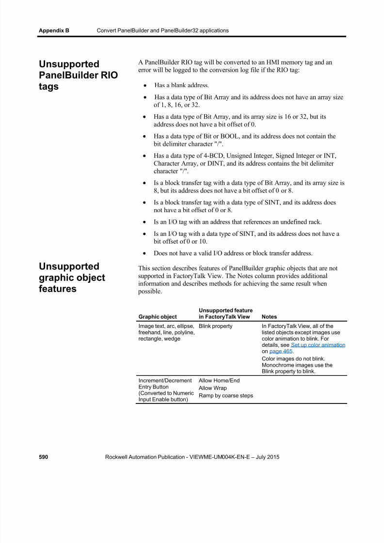
8/15/2019 Factory Talk View ME
http://slidepdf.com/reader/full/factory-talk-view-me 590/635
Appendix B Convert PanelBuilder and PanelBuilder32 applications
590 Rockwell Automation Publication - VIEWME-UM004K-EN-E – July 2015
A PanelBuilder RIO tag will be converted to an HMI memory tag and anerror will be logged to the conversion log file if the RIO tag:
Has a blank address.
Has a data type of Bit Array and its address does not have an array sizeof 1, 8, 16, or 32.
Has a data type of Bit Array, and its array size is 16 or 32, but itsaddress does not have a bit offset of 0.
Has a data type of Bit or BOOL, and its address does not contain the bit delimiter character "/".
Has a data type of 4-BCD, Unsigned Integer, Signed Integer or INT,Character Array, or DINT, and its address contains the bit delimitercharacter "/".
Is a block transfer tag with a data type of Bit Array, and its array size is8, but its address does not have a bit offset of 0 or 8.
Is a block transfer tag with a data type of SINT, and its address doesnot have a bit offset of 0 or 8.
Is an I/O tag with an address that references an undefined rack.
Is an I/O tag with a data type of SINT, and its address does not have a bit offset of 0 or 10.
Does not have a valid I/O address or block transfer address.
This section describes features of PanelBuilder graphic objects that are not
supported in FactoryTalk View. The Notes column provides additionalinformation and describes methods for achieving the same result when possible.
Graphic objectUnsupported featurein FactoryTalk View Notes
Image text, arc, ellipse,freehand, line, polyline,rectangle, wedge
Blink property In FactoryTalk View, all of thelisted objects except images usecolor animation to blink. Fordetails, see Set up color animation on page 465 . Color images do not blink.Monochrome images use the
Blink property to blink. Increment/DecrementEntry Button(Converted to NumericInput Enable button)
Allow Home/End Allow WrapRamp by coarse steps
UnsupportedPanelBuilder RIOtags
Unsupported
graphic objectfeatures
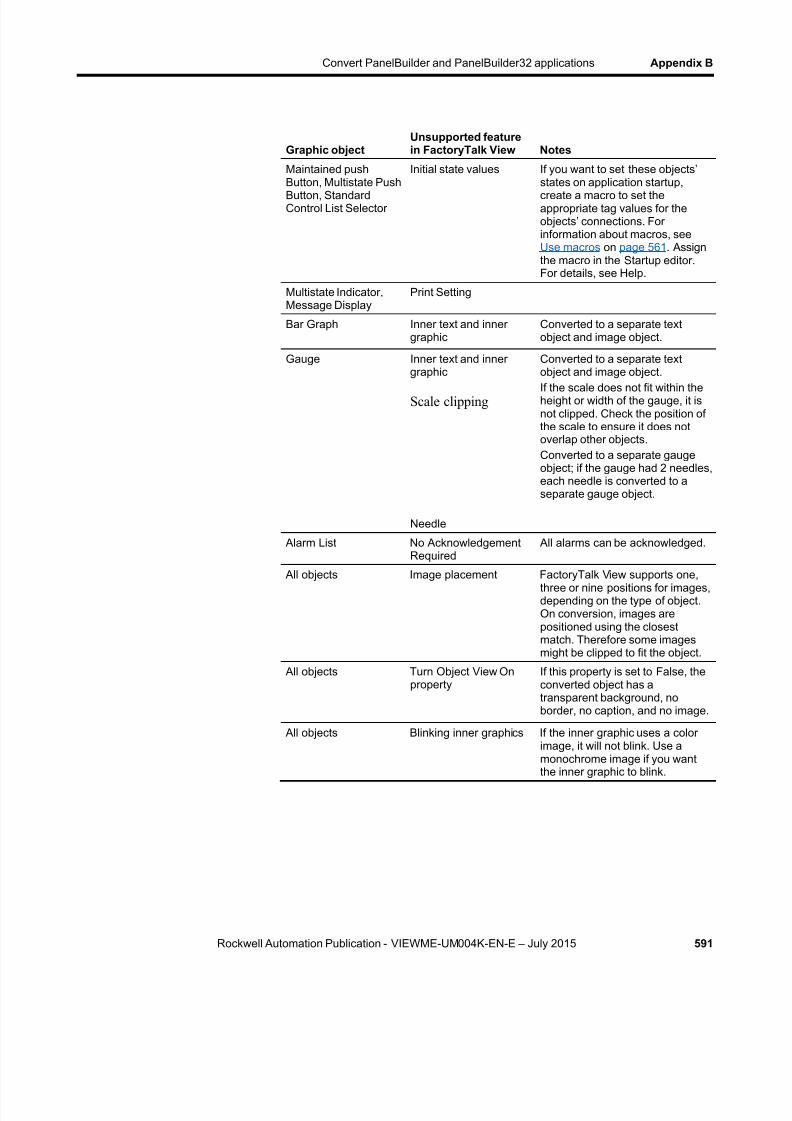
8/15/2019 Factory Talk View ME
http://slidepdf.com/reader/full/factory-talk-view-me 591/635
Convert PanelBuilder and PanelBuilder32 applications Appendix B
Rockwell Automation Publication - VIEWME-UM004K-EN-E – July 2015 591
Graphic objectUnsupported featurein FactoryTalk View Notes
Maintained pushButton, Multistate PushButton, StandardControl List Selector
Initial state values If you want to set these objects’states on application startup,create a macro to set theappropriate tag values for theobjects’ connections. Forinformation about macros, seeUse macros on page 561 . Assignthe macro in the Startup editor.For details, see Help.
Multistate Indicator,Message Display
Print Setting
Bar Graph Inner text and innergraphic
Converted to a separate textobject and image object.
Gauge Inner text and innergraphic
Scale clipping
Needle
Converted to a separate textobject and image object.If the scale does not fit within theheight or width of the gauge, it isnot clipped. Check the position ofthe scale to ensure it does notoverlap other objects.Converted to a separate gaugeobject; if the gauge had 2 needles,each needle is converted to aseparate gauge object.
Alarm List No AcknowledgementRequired
All alarms can be acknowledged.
All objects Image placement FactoryTalk View supports one,three or nine positions for images,depending on the type of object.On conversion, images arepositioned using the closestmatch. Therefore some imagesmight be clipped to fit the object.
All objects Turn Object View Onproperty
If this property is set to False, theconverted object has atransparent background, noborder, no caption, and no image.
All objects Blinking inner graphics If the inner graphic uses a colorimage, it will not blink. Use amonochrome image if you wantthe inner graphic to blink.

8/15/2019 Factory Talk View ME
http://slidepdf.com/reader/full/factory-talk-view-me 592/635
Appendix B Convert PanelBuilder and PanelBuilder32 applications
592 Rockwell Automation Publication - VIEWME-UM004K-EN-E – July 2015

8/15/2019 Factory Talk View ME
http://slidepdf.com/reader/full/factory-talk-view-me 593/635
Rockwell Automation Publication - VIEWME-UM004K-EN-E – July 2015 593
App end ix C
System tags
This appendix describes system tags.
System tags are pre-configured HMI tags created by FactoryTalk View.System tags are read-only. Show them as needed in your application.
The following tag contains the time and date when the status of alarms waslast reset. The date uses the long date format.
Tag name Type Function
system\AlarmResetDateAndTimeString
String Contains the date and time ofthe last alarm reset.
For information about resetting alarms, see Methods for resetting alarms on page 127 .
The following HMI tags can be used to make graphic objects appear asthough they are blinking on and off:
Tag name Type Function
system\BlinkFast Digital Toggles on and off every 100ms (10 times per second).
system\BlinkSlow Digital Toggles on and off every 500ms (twice per second).
A more efficient way to make graphic objects blink is to use the blinkingcolor option in color animation. For details, see Set up color animation on
page 465 .
Also, many objects have a Blink property that you can set up. For
information about specific objects, see Help.
These HMI tags record time and date information in various formats:
Tag Name Type Provides this data Read or write
system\Date String System date. Read only
system\DateAndTimeInteger
Analog Number of seconds elapsedsince midnight (00:00:00)January 1, 1970,coordinated universal time.
Read only
Alarms
Graphics
Time
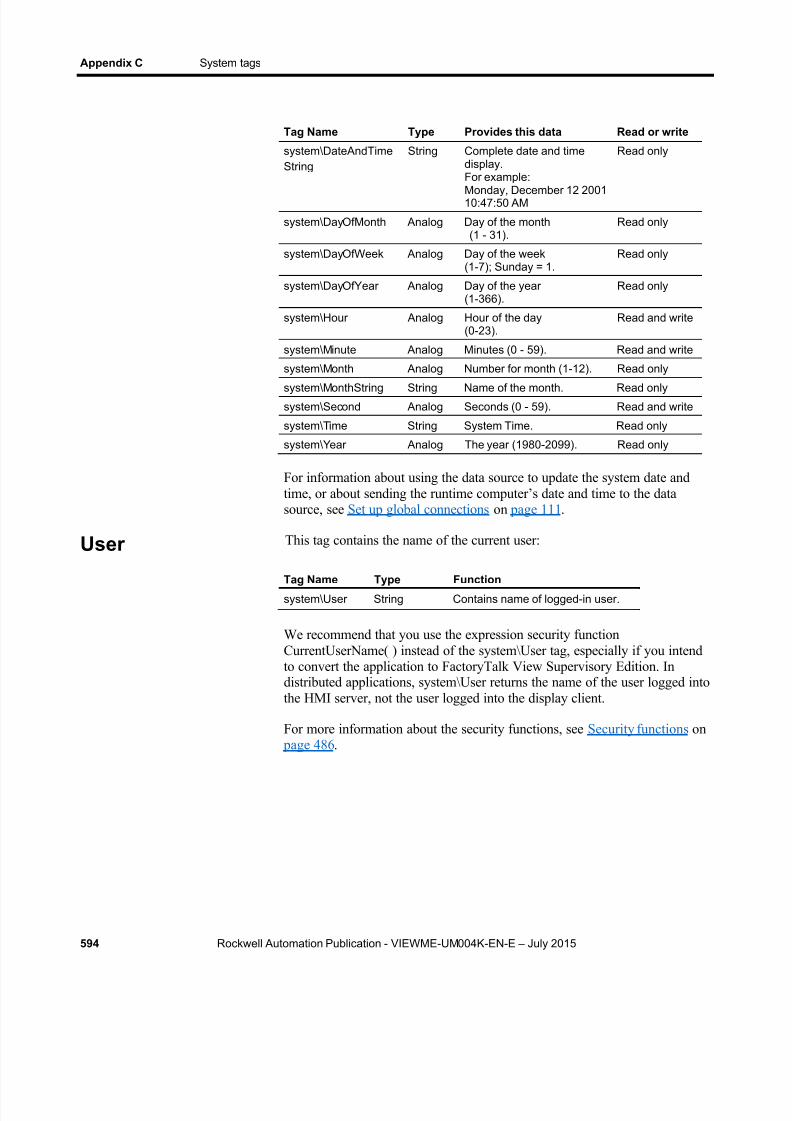
8/15/2019 Factory Talk View ME
http://slidepdf.com/reader/full/factory-talk-view-me 594/635
Appendix C System tags
594 Rockwell Automation Publication - VIEWME-UM004K-EN-E – July 2015
Tag Name Type Provides this data Read or write
system\DateAndTimeString
String Complete date and timedisplay.For example:
Monday, December 12 200110:47:50 AM
Read only
system\DayOfMonth Analog Day of the month(1 - 31).
Read only
system\DayOfWeek Analog Day of the week(1-7); Sunday = 1.
Read only
system\DayOfYear Analog Day of the year(1-366).
Read only
system\Hour Analog Hour of the day(0-23).
Read and write
system\Minute Analog Minutes (0 - 59). Read and write
system\Month Analog Number for month (1-12). Read only
system\MonthString String Name of the month. Read only
system\Second Analog Seconds (0 - 59). Read and write
system\Time String System Time. Read only
system\Year Analog The year (1980-2099). Read only
For information about using the data source to update the system date andtime, or about sending the runtime computer’s date and time to the datasource, see Set up global connections on page 111 .
This tag contains the name of the current user:
Tag Name Type Function
system\User String Contains name of logged-in user.
We recommend that you use the expression security functionCurrentUserName( ) instead of the system\User tag, especially if you intendto convert the application to FactoryTalk View Supervisory Edition. Indistributed applications, system\User returns the name of the user logged intothe HMI server, not the user logged into the display client.
For more information about the security functions, see Security functions on page 486 .
User
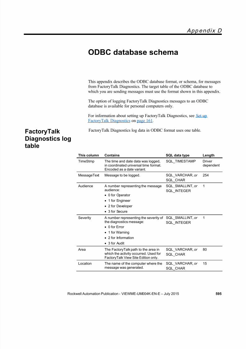
8/15/2019 Factory Talk View ME
http://slidepdf.com/reader/full/factory-talk-view-me 595/635
Rockwell Automation Publication - VIEWME-UM004K-EN-E – July 2015 595
App end ix D
ODBC database schema
This appendix describes the ODBC database format, or schema, for messagesfrom FactoryTalk Diagnostics. The target table of the ODBC database towhich you are sending messages must use the format shown in this appendix.
The option of logging FactoryTalk Diagnostics messages to an ODBCdatabase is available for personal computers only.
For information about setting up FactoryTalk Diagnostics, see Set upFactoryTalk Diagnostics on page 161 .
FactoryTalk Diagnostics log data in ODBC format uses one table.
This column Contains SQL data type Length
TimeStmp The time and date data was logged,in coordinated universal time format.Encoded as a date variant.
SQL_TIMESTAMP Driverdependent
MessageText Message to be logged. SQL_VARCHAR, or SQL_CHAR
254
Audience A number representing the messageaudience: 0 for Operator
1 for Engineer
2 for Developer
3 for Secure
SQL_SMALLINT, or SQL_INTEGER
1
Severity A number representing the severity ofthe diagnostics message: 0 for Error
1 for Warning
2 for Information 3 for Audit
SQL_SMALLINT, or SQL_INTEGER
1
Area The FactoryTalk path to the area inwhich the activity occurred. Used forFactoryTalk View Site Edition only.
SQL_VARCHAR, or SQL_CHAR
80
Location The name of the computer where themessage was generated.
SQL_VARCHAR, or SQL_CHAR
15
FactoryTalkDiagnostics logtable

8/15/2019 Factory Talk View ME
http://slidepdf.com/reader/full/factory-talk-view-me 596/635
Appendix D ODBC database schema
596 Rockwell Automation Publication - VIEWME-UM004K-EN-E – July 2015
This column Contains SQL data type Length
UserID The name of the user (includingdomain name, if there is one) thatinitiated the action that caused the
diagnostics message. If thediagnostics message was caused byan HMI server, the user columncontains "System."
SQL_VARCHAR, or SQL_CHAR
38
UserFullName The full name of the user that waslogged in when the activity occurred.
SQL_VARCHAR, or SQL_CHAR
255
Provider The name of the product thatgenerated the message.
SQL_VARCHAR, or SQL_CHAR
20
8/15/2019 Factory Talk View ME
http://slidepdf.com/reader/full/factory-talk-view-me 597/635
Rockwell Automation Publication - VIEWME-UM004K-EN-E – July 2015 597
App end ix E
Import and export alarm XML files
This appendix describes:
Create alarm XML files
Export, editing, and importing XML files
The alarm XML file structure
XML is the Extensible Markup Language used to create documents withstructured text information. It has a standardized format and structure. Youcan use XML to edit the elements and attributes needed to create an alarmsetup file or to modify graphic displays. For information about working withgraphics XML files, see Import and export graphics XML files on page 613 .
Sometimes editing your alarm setup in an XML file is quicker than workingin FactoryTalk View. For example, if you have a list of 100 tags to monitorfor alarms, with multiple messages for each tag, you might prefer to enter allthe information in a text editor, and then import the alarm setup informationinto FactoryTalk View.
Another example of using XML files is to export the alarm setup informationyou develop in one application, import the setup information to anotherFactoryTalk View application, and then modify the alarm setup as needed.Or, you could modify the information in the XML file before importing it.
For more information about XML, see the World Wide Web Consortium’sweb page about XML at http://www.w3.org/XML .
The quickest way to create an XML file for your application’s alarm setup isto export the data from FactoryTalk View. You can then open the XML filein Notepad, make your changes, and import the file back into FactoryTalkView.
Note: The strings for the application’s current language are exportedto the XML file. To export strings for another language, reopenthe application in the new language and repeat the XMLexport.
About XML
Create alarm XMLfiles by exporting

8/15/2019 Factory Talk View ME
http://slidepdf.com/reader/full/factory-talk-view-me 598/635
Appendix E Import and export alarm XML files
598 Rockwell Automation Publication - VIEWME-UM004K-EN-E – July 2015
To export alarm information to an XML file
1. In the Explorer window, right-click the Alarm Setup editor.
2. Click Import and Export .
The Alarm Import Export Wizard opens.
3. Follow the instructions in the wizard.
For information about using the Alarm Import Export Wizard, seeHelp.
FactoryTalk View creates a file with the name you specify, in the locationyou specify.
We recommend that you use Notepad to edit your XML files.
If you do not want to change a prope rty, you don’t need to include it in theXML file.
Save XML files in Notepad
Save XML files created or edited in Notepad using either UTF-8 or UTF-16file format. Notepad’s Unicode file type corresponds to UTF -16 file format.For files containing strings in English or other Latin-based languages, UTF-8
is recommended, to reduce the size of the XML file. For other languagessuch as Chinese, Japanese, or Korean, UTF-16 is recommended.
The first line of every XML file contains XML version and encodingattributes. Make sure the encoding attribute matches the format that you aregoing to use when you save the file. For example, if the original file wassaved in UTF-8 format and you plan to save it in UTF-16 format, make surethe first line specifies encoding="UTF-16".
Test XML files
An XML file must be well-formed to be imported. To find out whether yourXML file is well-formed, test it.
To test an XML fi le
Open the XML file in Internet Explorer.
If you can see the XML code, your file is well-formed. If the XML code isnot well-formed, Internet Explorer shows an error message.
Edit XML files
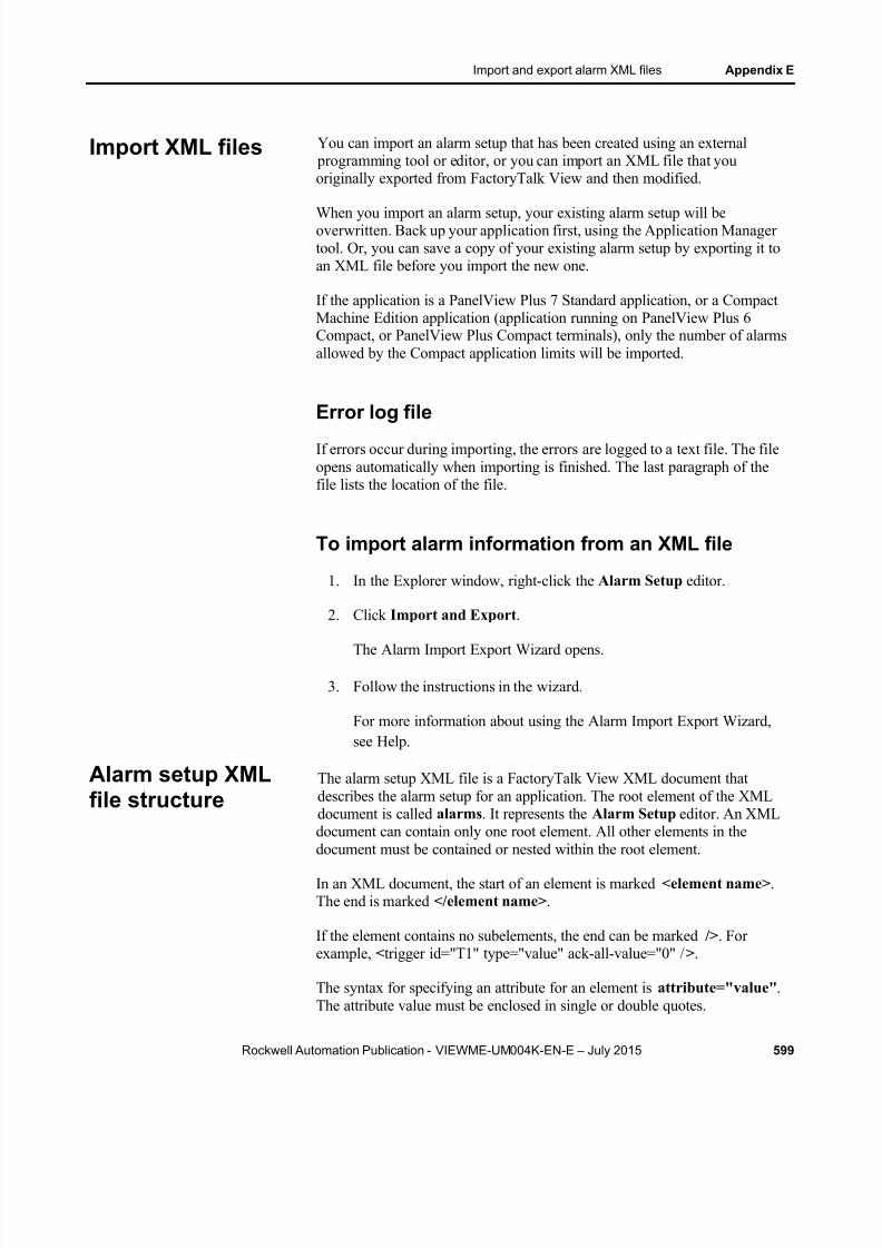
8/15/2019 Factory Talk View ME
http://slidepdf.com/reader/full/factory-talk-view-me 599/635
Import and export alarm XML files Appendix E
Rockwell Automation Publication - VIEWME-UM004K-EN-E – July 2015 599
You can import an alarm setup that has been created using an external programming tool or editor, or you can import an XML file that youoriginally exported from FactoryTalk View and then modified.
When you import an alarm setup, your existing alarm setup will beoverwritten. Back up your application first, using the Application Managertool. Or, you can save a copy of your existing alarm setup by exporting it toan XML file before you import the new one.
If the application is a PanelView Plus 7 Standard application, or a CompactMachine Edition application (application running on PanelView Plus 6Compact, or PanelView Plus Compact terminals), only the number of alarmsallowed by the Compact application limits will be imported.
Error log file
If errors occur during importing, the errors are logged to a text file. The fileopens automatically when importing is finished. The last paragraph of thefile lists the location of the file.
To import alarm information from an XML file
1. In the Explorer window, right-click the Alarm Setup editor.
2. Click Import and Export .
The Alarm Import Export Wizard opens.
3. Follow the instructions in the wizard.
For more information about using the Alarm Import Export Wizard,see Help.
The alarm setup XML file is a FactoryTalk View XML document thatdescribes the alarm setup for an application. The root element of the XMLdocument is called alarms . It represents the Alarm Setup editor. An XMLdocument can contain only one root element. All other elements in the
document must be contained or nested within the root element.
In an XML document, the start of an element is marked <element name> .The end is marked </element name> .
If the element contains no subelements, the end can be marked /> . Forexample, <trigger id="T1" type="value" ack-all-value="0" / >.
The syntax for specifying an attribute for an element is attribute="value" .The attribute value must be enclosed in single or double quotes.
Import XML files
Alarm setup XMLfile structure
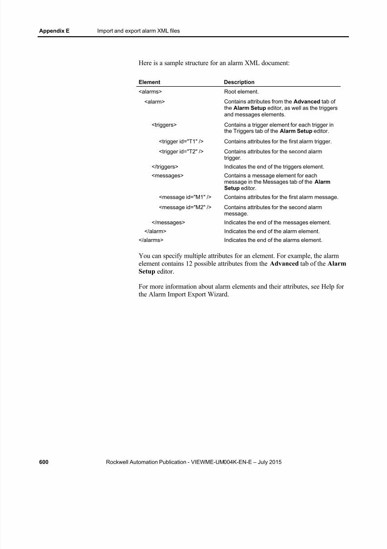
8/15/2019 Factory Talk View ME
http://slidepdf.com/reader/full/factory-talk-view-me 600/635
Appendix E Import and export alarm XML files
600 Rockwell Automation Publication - VIEWME-UM004K-EN-E – July 2015
Here is a sample structure for an alarm XML document:
Element Description
<alarms> Root element.<alarm> Contains attributes from the Advanced tab of
the Alarm Setup editor, as well as the triggersand messages elements.
<triggers> Contains a trigger element for each trigger inthe Triggers tab of the Alarm Setup editor.
<trigger id="T1" /> Contains attributes for the first alarm trigger.
<trigger id="T2" /> Contains attributes for the second alarmtrigger.
</triggers> Indicates the end of the triggers element.
<messages> Contains a message element for eachmessage in the Messages tab of the AlarmSetup editor.
<message id="M1" /> Contains attributes for the first alarm message.
<message id="M2" /> Contains attributes for the second alarmmessage.
</messages> Indicates the end of the messages element.
</alarm> Indicates the end of the alarm element.
</alarms> Indicates the end of the alarms element.
You can specify multiple attributes for an element. For example, the alarmelement contains 12 possible attributes from the Advanced tab of the AlarmSetup editor.
For more information about alarm elements and their attributes, see Help forthe Alarm Import Export Wizard.
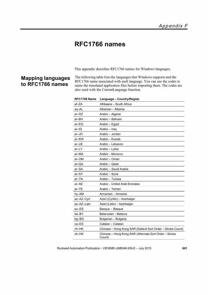
8/15/2019 Factory Talk View ME
http://slidepdf.com/reader/full/factory-talk-view-me 601/635
Rockwell Automation Publication - VIEWME-UM004K-EN-E – July 2015 601
App end ix F
RFC1766 names
This appendix describes RFC1766 names for Windows languages.
The following table lists the languages that Windows supports and theRFC1766 name associated with each language. You can use the codes toname the translated application files before importing them. The codes arealso used with the CurrentLanguage function.
RFC1766 Name Language – Country/Region
af – ZA Afrikaans – South Africa
sq – AL Albanian – Albania
ar – DZ Arabic – Algeria
ar – BH Arabic – Bahrain
ar – EG Arabic – Egypt
ar – IQ Arabic – Iraq
ar – JO Arabic – Jordan
ar – KW Arabic – Kuwait
ar – LB Arabic – Lebanon
ar – LY Arabic – Lybia
ar – MA Arabic – Morocco
ar – OM Arabic – Oman
ar – QA Arabic – Qatar
ar – SA Arabic – Saudi Arabia
ar – SY Arabic – Syria
ar – TN Arabic – Tunisia
ar – AE Arabic – United Arab Emirates
ar – YE Arabic – Yemen
hy – AM Armenian – Armenia
az – AZ – Cyrl Azeri (Cyrillic) – Azerbaijan
az – AZ – Latn Azeri (Latin) – Azerbaijan
eu – ES Basque – Basque
be – BY Belarusian – Belarus
bg – BG Bulgarian – Bulgaria
ca – ES Catalan – Catalan
zh – HK Chinese – Hong Kong SAR (Default Sort Order – Stroke Count)
zh – HK Chinese – Hong Kong SAR (Alternate Sort Order – StrokeCount)
Mapping languagesto RFC1766 names
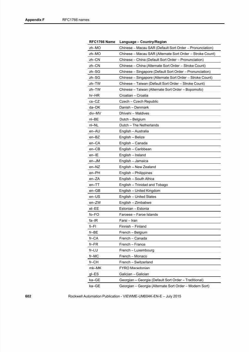
8/15/2019 Factory Talk View ME
http://slidepdf.com/reader/full/factory-talk-view-me 602/635
Appendix F RFC1766 names
602 Rockwell Automation Publication - VIEWME-UM004K-EN-E – July 2015
RFC1766 Name Language – Country/Region
zh – MO Chinese – Macau SAR (Default Sort Order – Pronunciation)
zh – MO Chinese – Macau SAR (Alternate Sort Order – Stroke Count)
zh – CN Chinese – China (Default Sort Order – Pronunciation)zh – CN Chinese – China (Alternate Sort Order – Stroke Count)
zh – SG Chinese – Singapore (Default Sort Order – Pronunciation)
zh – SG Chinese – Singapore (Alternate Sort Order – Stroke Count)
zh – TW Chinese – Taiwan (Default Sort Order – Stroke Count)
zh – TW Chinese – Taiwan (Alternate Sort Order – Bopomofo)
hr – HR Croatian – Croatia
cs – CZ Czech – Czech Republic
da – DK Danish – Denmark
div – MV Dhivehi – Maldives
nl – BE Dutch – Belgiumnl – NL Dutch – The Netherlands
en – AU English – Australia
en – BZ English – Belize
en – CA English – Canada
en – CB English – Caribbean
en – IE English – Ireland
en – JM English – Jamaica
en – NZ English – New Zealand
en – PH English – Philippines
en – ZA English – South Africaen – TT English – Trinidad and Tobago
en – GB English – United Kingdom
en – US English – United States
en – ZW English – Zimbabwe
et – EE Estonian – Estonia
fo – FO Faroese – Faroe Islands
fa – IR Farsi – Iran
fi – FI Finnish – Finland
fr – BE French – Belgium
fr – CA French – Canada
fr – FR French – France
fr – LU French – Luxembourg
fr – MC French – Monaco
fr – CH French – Switzerland
mk – MK FYRO Macedonian
gl – ES Galician – Galician
ka – GE Georgian – Georgia (Default Sort Order – Traditional)
ka – GE Georgian – Georgia (Alternate Sort Order – Modern Sort)

8/15/2019 Factory Talk View ME
http://slidepdf.com/reader/full/factory-talk-view-me 603/635
RFC1766 names Appendix F
Rockwell Automation Publication - VIEWME-UM004K-EN-E – July 2015 603
RFC1766 Name Language – Country/Region
de – AT German – Austria
de – DE German – Germany (Default Sort Order – Dictionary)
de – DE German – Germany (Alternate Sort Order – Phone Book SortDIN)
de – LI German – Liechtenstein
de – LU German – Luxembourg
de – CH German – Switzerland
el – GR Greek – Greece
gu – IN Gujarati – India
he – IL Hebrew – Israel
hi – IN Hindi – India
hu – HU Hungarian – Hungary (Default Sort Order)
hu – HU Hungarian – Hungary (Alternate Sort Order – Technical Sort)
is – IS Icelandic – Iceland
id – ID Indonesian – Indonesia
it – IT Italian – Italy
it – CH Italian – Switzerland
ja – JP Japanese – Japan (Default Sort Order)
ja – JP Japanese – Japan (Alternate Sort Order – Unicode)
kn – IN Kannada – India
kk – KZ Kazakh – Kazakhstan
kok – IN Konkani – India
ko – KR Korean – Korea (Default Sort Order)
ko – KR Korean – Korea (Alternate Sort Order – Korean XwansungUnicode)
ky – KZ Kyrgyz – Kazakhstan
lv – LV Latvian – Latvia
lt – LT Lithuanian – Lithuania
ms – BN Malay – Brunei
ms – MY Malay – Malaysia
mr – IN Marathi – India
mn – MN Mongolian – Mongolia
nb – NO Norwegian (Bokml) – Norway
nn – NO Norwegian (Nynorsk) – Norwaypl – PL Polish – Poland
pt – BR Portuguese – Brazil
pt – PT Portuguese – Portugal
pa – IN Punjabi – India
ro – RO Romanian – Romania
ru – RU Russian – Russia
sa – IN Sanskrit – India

8/15/2019 Factory Talk View ME
http://slidepdf.com/reader/full/factory-talk-view-me 604/635
Appendix F RFC1766 names
604 Rockwell Automation Publication - VIEWME-UM004K-EN-E – July 2015
RFC1766 Name Language – Country/Region
sr – SP – Cyrl Serbian (Cyrillic) – Serbia
sr – SP – Latn Serbian (Latin) – Serbia
sk – SK Slovak – Slovakiasl – SI Slovenian – Slovenia
es – AR Spanish – Argentina
es – BO Spanish – Bolivia
es – CL Spanish – Chile
es – CO Spanish – Colombia
es – CR Spanish – Costa Rica
es – DO Spanish – Dominican Republic
es – EC Spanish – Ecuador
es – SV Spanish – El Salvador
es – GT Spanish – Guatemalaes – HN Spanish – Honduras
es – MX Spanish – Mexico
es – NI Spanish – Nicaragua
es – PA Spanish – Panama
es – PY Spanish – Paraguay
es – PE Spanish – Peru
es – PR Spanish – Puerto Rico
es – ES Spanish – Spain (Default Sort Order – International)
es – ES Spanish – Spain (Alternate Sort Order – Traditional)
es – UY Spanish – Uruguayes – VE Spanish – Venezuela
sw – KE Swahili – Kenya
sv – FI Swedish – Finland
sv – SE Swedish – Sweden
syr – SY Syriac – Syria
ta – IN Tamil – India
tt – RU Tatar – Russia
te – IN Telugu – India
th – TH Thai – Thailand
tr – TR Turkish – Turkey
uk – UA Ukrainian – Ukraine
ur – PK Urdu – Pakistan
uz – UZ – Cyrl Uzbek (Cyrillic) – Uzbekistan
uz – UZ – Latn Uzbek (Latin) – Uzbekistan
vi – VN Vietnamese – Vietnam
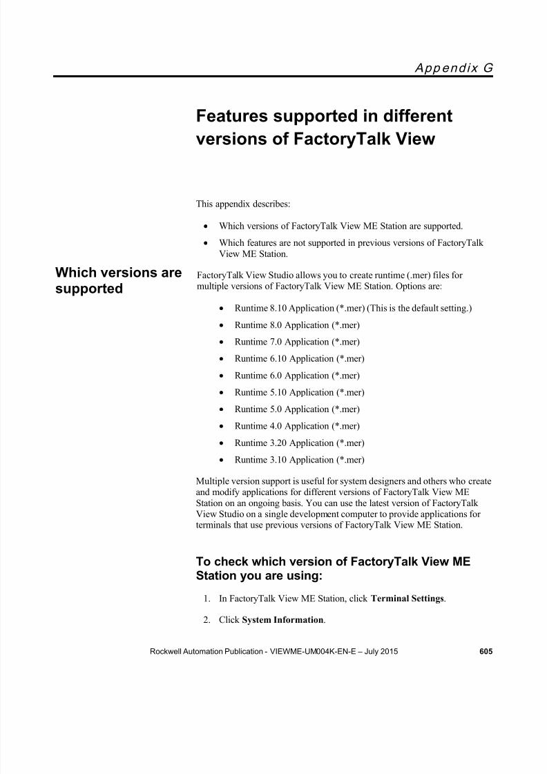
8/15/2019 Factory Talk View ME
http://slidepdf.com/reader/full/factory-talk-view-me 605/635
Rockwell Automation Publication - VIEWME-UM004K-EN-E – July 2015 605
App end ix G
Features supported in differentversions of FactoryTalk View
This appendix describes:
Which versions of FactoryTalk View ME Station are supported.
Which features are not supported in previous versions of FactoryTalkView ME Station.
FactoryTalk View Studio allows you to create runtime (.mer) files formultiple versions of FactoryTalk View ME Station. Options are:
Runtime 8.10 Application (*.mer) (This is the default setting.)
Runtime 8.0 Application (*.mer)
Runtime 7.0 Application (*.mer)
Runtime 6.10 Application (*.mer)
Runtime 6.0 Application (*.mer)
Runtime 5.10 Application (*.mer) Runtime 5.0 Application (*.mer)
Runtime 4.0 Application (*.mer)
Runtime 3.20 Application (*.mer)
Runtime 3.10 Application (*.mer)
Multiple version support is useful for system designers and others who createand modify applications for different versions of FactoryTalk View MEStation on an ongoing basis. You can use the latest version of FactoryTalkView Studio on a single development computer to provide applications for
terminals that use previous versions of FactoryTalk View ME Station.
To check which version of FactoryTalk View MEStation you are using:
1. In FactoryTalk View ME Station, click Terminal Settings .
2. Click System Information .
Which versions aresupported

8/15/2019 Factory Talk View ME
http://slidepdf.com/reader/full/factory-talk-view-me 606/635
Appendix G Features supported in different versions of FactoryTalk View
606 Rockwell Automation Publication - VIEWME-UM004K-EN-E – July 2015
3. Click About FactoryTalk View ME Station .
When you create the runtime application file (with the file extension .mer),you can specify the version of FactoryTalk View ME Station for which to
create the file. For example, if the application will run on a terminal that usesRSView ME Station version 3.20, you can specify that version for the .merfile.
If the application contains features that are not supported by the version youselect, FactoryTalk View shows a validation report that lists the unsupportedfeatures. The runtime application file is not created. You must remove or turnoff the unsupported features before you can create the runtime applicationfile.
For information about creating runtime application files, see Create runtimeapplications on page 221 .
The remainder of this appendix lists the features that are not supported in previous versions of FactoryTalk View ME Station. The tables also showhow to remove or replace the unsupported features.
These version 8.0 features are not supported in version 7.00 of FactoryTalkView ME Station, nor in earlier versions. The right column describes how toremove or replace the feature.
To remove or replace thisfeature Do this
Add User/Group button Delete the button object from GraphicDisplays .
Delete User/Group button Delete the button object from GraphicDisplays .
Modify Group Membershipbutton
Delete the button object from GraphicDisplays .
Unlock User button Delete the button object from GraphicDisplays .
Enable User button Delete the button object from GraphicDisplays .
Disable User button Delete the button object from GraphicDisplays .
Login button Clear the Domain name and User name fieldsin the General tab of Login Button Properties window.
Password button Clear the Change any user password(Administrative) option in the General tab ofPassword Button Properties window.
Change User Properties button Delete the button object from GraphicDisplays .
Create runtime
application files forprevious versions
Features that arenot supported inversion 7.00 orearlier

8/15/2019 Factory Talk View ME
http://slidepdf.com/reader/full/factory-talk-view-me 607/635
Features supported in different versions of FactoryTalk View Appendix G
Rockwell Automation Publication - VIEWME-UM004K-EN-E – July 2015 607
These version 7.0 features are not supported in version 6.10 of FactoryTalkView ME Station, nor in earlier versions. The right column describes how toremove or replace the feature.
To remove or replace thisfeature Do this
ME Alarm Embedded ServerUpdate Rate
Select Match Alarm Update Rate or the samenumber as Maximum update rate in the Advance Tab of Alarm Setup editor.
MAXIMUM DATA POINTSenlargement support.
Change the Maximum data points value to beequal to or less than 300000 in the Setup tab ofData Log Models editor.
Parameterized Macro buttonClear Use Variable Macro check box in theGeneral tab of Macro button property page.
Parameterized Goto displaybutton
Clear Use Variable Display check box in theGeneral tab of Goto display button property page.
Parameterized displayposition
Clear Use Variable Display Position check box inthe General tab of Goto display button propertypage.
Graphic Objects configuredwith Gradient Shadingbackground;
Change the Gradient Shading background style toSolid or Transparent.Delete Gradient animation from Graphics Objectsanimation. Or user can select other Fill Styles incolor animation to create version 6.1 mer.
PNG image support Delete PNG image object from Graphic Displays .
These version 6.0 features are not supported in version 5.10 of FactoryTalkView ME Station, nor in earlier versions. The right column describes how toremove or replace the feature.
To remove or replace thisfeature Do this
Graphics objects with Shadedand Original animation is notsupport on v5.10 or earlierrelease.
Delete the Shaded or Original animation fromGraphics objects animation.Or
User can select Solid in Fill Style to createversion5.1 mer
Features that arenot supported inversion 6.10 orearlier
Features that arenot supported inversion 5.10 orearlier

8/15/2019 Factory Talk View ME
http://slidepdf.com/reader/full/factory-talk-view-me 608/635
Appendix G Features supported in different versions of FactoryTalk View
608 Rockwell Automation Publication - VIEWME-UM004K-EN-E – July 2015
These version 5.10 features are not supported in version 5.00 of FTView MEStation, nor in earlier versions. The right column describes how to remove orreplace the feature.
To remove or replace this feature Do this
Tag or expression assigned to theClose an On Top Display , or CloseAll On Top Displays connections
Delete the tag or expression assigned in theDisplay tab of the Global Connections editor.
Tag or expression assigned to theParameter File , or Use ParameterList connections
Delete the tag or expression assigned in theDisplay tab of the Global Connections editor.
Tag or expression assigned to one ormore of the Parameter Tag #1-10 connections
Delete the tag or expression in the Display tab of the Global Connections editor.
Parameter list property assigned inthe Properties dialog box of aDisplay List Selector, Goto displaybutton, or Logout button graphicobject
In the object’s Properties dialog box, clearthe Parameter list assignment.
Parameter list property assigned tothe display specified for auto logout inProject Settings
In the Project Settings editor’s Runtime tab, clear the Parameter list assignment.
Parameter list assigned to the Initialgraphic property in the Startup editor
In the Startup editor, clear the Parameterlist assignment for the Initial graphic .
Use variable minimum/maximum property assigned to Numeric InputCursor Point or Numeric InputEnable object
In the Numeric tab of the object’sProperties dialog box, clear the Usevariable minimum/maximum property.
Caption on Keypad propertyassigned to Numeric Input CursorPoint object
In the Numeric tab of the object’sProperties dialog box, set the Caption onkeypad/scratchpad property to blank.
Minimum or Maximum connectionsassigned for Numeric Input CursorPoint or Numeric Input Enableobject
In the Connections tab of the object’sProperties dialog box, delete the tag orexpression assigned to the Minimum orMaximum connection.
Use variable ramp or Use variablelimit property set for the Rampbutton object
In the General tab of the object’sProperties dialog box, clear the Usevariable lower/upper limit and Usevariable ramp value properties.
Ramp or Limit connection set for theRamp button object
In the Connections tab of the object’sProperties dialog box, delete the tag orexpression assigned to the Ramp or Limitconnection.
The application is designated as aCompact Machine Edition applicationin Project Settings
In the General tab of the Project Settingseditor, clear the Compact Machine Editionapplication check box.
Features that arenot supported inversion 5.00 orearlier

8/15/2019 Factory Talk View ME
http://slidepdf.com/reader/full/factory-talk-view-me 609/635
Features supported in different versions of FactoryTalk View Appendix G
Rockwell Automation Publication - VIEWME-UM004K-EN-E – July 2015 609
These version 5.00 features are not supported in version 4.00 of RSView MEStation, nor in earlier versions. The right column describes how to remove orreplace the feature.
To remove or replace thisfeature Do this
Delete action assigned to aRecipePlus button graphicobject
Delete the button or change the action toDownload, Upload, Upload and Create, Restore,or Save.
Rename action assigned to aRecipePlus button graphicobject
Delete the button or change the action toDownload, Upload, Upload and Create, Restore,or Save.
Display undefined stringsusing the default language option
In the Language Configuration dialog box,clear the option’s check box.
Tag assigned to theMERuntime RAM Usage ,Total RAM Usage , orAvailable RAM connection
Unassign the tag in the Memory tab of theGlobal Connections editor.
Tag or expression assigned tothe Remote RAM Usage connection
Unassign the tag or expression in the Memorytab of the Global Connections editor.
CaptionOnBorder propertyassigned to graphic object
In the Property Panel , set the object’sCaptionOnBorder property to False.
Embedded variable "L"character assigned to a captionor message
Select the Tag option in the Numeric Variableor String Variable dialog box for the caption ormessage.
Minus sign (-) qualifier used toshow right-most text assignedto a caption or message
Clear the Right-most characters in string aredisplayed check box in the String Variable dialog box for the caption or message.
SHOWSTAR qualifier assignedto a caption or message
Clear the Show* character if string is longerthan field width check box in the StringVariable dialog box for the caption or message.
Embedded variable assignedto the title bar of an On Topdisplay
Remove the embedded variable.
RSLinx Enterprise Remote I/Oalias with a BitArray data type
Assign a different data type to the alias.
Global object parameterdefinition or value
Delete the global object parameter definition.The corresponding value will be deletedautomatically. Use parameter files instead.
The features listed in the previous table are not supported in version 3.20 ofRSView ME Station. In addition, these version 4.00 features are notsupported in version 3.20 of RSView ME Station, nor in earlier versions.The right column describes how to remove or replace the feature.
Features that arenot supported inversion 4.00 orearlier
Features that arenot supported inversion 3.20 orearlier

8/15/2019 Factory Talk View ME
http://slidepdf.com/reader/full/factory-talk-view-me 610/635
Appendix G Features supported in different versions of FactoryTalk View
610 Rockwell Automation Publication - VIEWME-UM004K-EN-E – July 2015
To remove or replace thisfeature Do this
Unsupported RSLinxEnterprise feature or shortcut
warning
Delete or replace the feature or shortcut. A hardware patch might be available that allows
you to use the feature. Therefore, the runtimeapplication file will still be created.
Unsupported RSLinxEnterprise feature or shortcuterror
Delete or replace the feature or shortcut.
Global reference object that isnot linked to a global baseobject
Delete the global reference object, or link it to aglobal base object.
All global reference objects that are linked toglobal base objects will be converted tostandard graphic objects in the .mer file.
Language Switch buttongraphic object
Delete the button.
Password button graphicobject
Delete the button.
RecipePlus button graphicobject
Delete the button.
RecipePlus selector graphicobject
Delete the selector.
RecipePlus table graphicobject
Delete the table.
Acknowledge all alarms buttonwith a filtered trigger
Clear the Filtered triggers box.
Print alarm history button witha filtered trigger
Clear the Filtered triggers box.
Print alarm status button with afiltered trigger
Clear the Filtered triggers box.
Clear alarm history button witha filtered trigger
Clear the Filtered triggers box.
Clear alarm history button withthe Reset alarm status optioncleared
Select Reset alarm status .
The features listed in the previous tables are not supported in version 3.10 ofRSView ME Station. In addition, these version 3.20 alarm options are not
supported in version 3.10, nor in earlier versions. The right column describeshow to remove or replace the feature.
Features that are
not supported inversion 3.10 orearlier

8/15/2019 Factory Talk View ME
http://slidepdf.com/reader/full/factory-talk-view-me 611/635
Features supported in different versions of FactoryTalk View Appendix G
Rockwell Automation Publication - VIEWME-UM004K-EN-E – July 2015 611
To remove or replace thisfeature Do this
Alarm list graphic object withan unsupported combination of
alarm conditions
Do one of the following: Select the Display check box for each alarm
condition Select the Display check box for only these
alarm conditions:
Active and unacknowledged
Inactive and unacknowledged.
Alarm list graphic object withBlink selected for one or morealarm conditions
For all alarm conditions that you are showing,clear the Blink check box.
Alarm list graphic object withUse alarm colors turned off forone or more alarm conditions
For all alarm conditions that you are showing,select the Use alarm colors check box.
Alarm list graphic object with
the Acknowledged symbolcolumn turned off
Select the Display column check box for the
Acknowledged symbol column.
Alarm list graphic object withan Acknowledged symbol otherthan *
Change the Acknowledged symbol to *.
Alarm list graphic object withthe Active symbol columnshown
Clear the Display column check box for theActive symbol column.
Alarm list graphic object withtags or expressions assignedto one or more connections
Clear the tags or expressions assigned to theconnections.
Alarm list graphic object withSelected alarm indicator set toCursor
Change the Selected alarm indicator toHighlight bar.
Alarm list graphic object withLines per alarm set to >1
Change the Lines per alarm to 1.
Alarm banner graphic objectwith Use alarm colors selected
Clear the Use alarm colors check box.
Alarm status list graphic objectwith Use alarm colors selected
Clear the Use alarm colors check box.
Alarm status list graphic objectwith Lines per alarm set to >1
Change the Lines per alarm to 1.
Alarm status list graphic objectwith a Fore color other thanwhite
Change the Fore colo r to white.

8/15/2019 Factory Talk View ME
http://slidepdf.com/reader/full/factory-talk-view-me 612/635
Appendix G Features supported in different versions of FactoryTalk View
612 Rockwell Automation Publication - VIEWME-UM004K-EN-E – July 2015

8/15/2019 Factory Talk View ME
http://slidepdf.com/reader/full/factory-talk-view-me 613/635
Rockwell Automation Publication - VIEWME-UM004K-EN-E – July 2015 613
App end ix H
Import and export graphics XMLfiles
This appendix describes:
Create graphics XML files
Export, edit, and import XML files
The graphics XML file structure
XML is the Extensible Markup Language used to create documents withstructured text information. It has a standardized format and structure. Youcan use XML to edit the elements and attributes needed to create an alarmsetup file or to modify graphic displays and global displays. For informationabout working with alarm XML files, see Import and export alarm XML files on page 597 .
Sometimes editing your display information in an XML file is quicker thanworking in FactoryTalk View. For example, if you have a list of 100 localmessages to set up for a graphic display, you might prefer to enter all theinformation in a text editor, and then import the display information intoFactoryTalk View.
For more information about XML, see the World Wide Web Consortium’sweb page about XML at:http://www.w3.org/XML .
The quickest way to create an XML file for your application’s graphicdisplays is to export the data from FactoryTalk View. You can then open theXML file in Notepad, make your changes, and import the file back intoFactoryTalk View.
Note: The strings for the application’s current language are exported
to the XML file. To export strings for another language, reopenthe application in the new language and repeat the XMLexport.
About XML
Create graphicsXML files byexporting

8/15/2019 Factory Talk View ME
http://slidepdf.com/reader/full/factory-talk-view-me 614/635
Appendix H Import and export graphics XML files
614 Rockwell Automation Publication - VIEWME-UM004K-EN-E – July 2015
To export graphic display information to an XMLfile
1. In the Explorer window, right-click the Displays editor, or the GlobalObjects editor.
2. Click Import and Export .
The Graphics Import Export Wizard opens.
3. Follow the instructions in the wizard.
For information about using the Graphics Import Export Wizard, seeHelp.
FactoryTalk View creates XML files for the selected graphic displays, in thelocation you specify.
FactoryTalk View also creates a file called BatchImport_ Applicationname .xml, in the same location. You can use this file to import multipledisplays at the same time. To import a different set of displays than youexported, edit the list of display names in the BatchImport_ Applicationname .xml file.
We recommend that you use Notepad to edit your XML files.
If you do not want to change a property, you don’t need to include it in theXML file. When you import the file, if you select the option Create newobjects in the display , properties that are not listed in the file are set to theirdefault values. If you select the option Update existing objects on thedisplay , only properties that are listed in the file are updated with importedinformation.
Note: If you include attributes for an object whose name does notmatch one of those in the graphic display, the attributes forthat object are not imported. Attributes for all other objects inthe file whose names do match the ones in the graphic displayare imported.
Save XML files in Notepad
Save XML files created or edited in Notepad using either UTF-8 or UTF-16file format. Notepad’s Unicode file type corresponds to UTF -16 file format.For files containing strings in English or other Latin-based languages, UTF-8is recommended, to reduce the size of the XML file. For other languagessuch as Chinese, Japanese, or Korean, UTF-16 is recommended.
Edit XML files
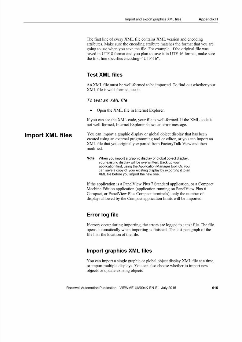
8/15/2019 Factory Talk View ME
http://slidepdf.com/reader/full/factory-talk-view-me 615/635
Import and export graphics XML files Appendix H
Rockwell Automation Publication - VIEWME-UM004K-EN-E – July 2015 615
The first line of every XML file contains XML version and encodingattributes. Make sure the encoding attribute matches the format that you aregoing to use when you save the file. For example, if the original file wassaved in UTF-8 format and you plan to save it in UTF-16 format, make sure
the first line specifies encoding="UTF-16".
Test XML files
An XML file must be well-formed to be imported. To find out whether yourXML file is well-formed, test it.
To test an XML fi le
Open the XML file in Internet Explorer.
If you can see the XML code, your file is well-formed. If the XML code isnot well-formed, Internet Explorer shows an error message.
You can import a graphic display or global object display that has beencreated using an external programming tool or editor, or you can import anXML file that you originally exported from FactoryTalk View and thenmodified.
Note: When you import a graphic display or global object display,your existing display will be overwritten. Back up yourapplication first, using the Application Manager tool. Or, youcan save a copy of your existing display by exporting it to an
XML file before you import the new one.
If the application is a PanelView Plus 7 Standard application, or a CompactMachine Edition application (application running on PanelView Plus 6Compact, or PanelView Plus Compact terminals), only the number ofdisplays allowed by the Compact application limits will be imported.
Error log file
If errors occur during importing, the errors are logged to a text file. The fileopens automatically when importing is finished. The last paragraph of thefile lists the location of the file.
Import graphics XML files
You can import a single graphic or global object display XML file at a time,or import multiple displays. You can also choose whether to import newobjects or update existing objects.
Import XML files

8/15/2019 Factory Talk View ME
http://slidepdf.com/reader/full/factory-talk-view-me 616/635
Appendix H Import and export graphics XML files
616 Rockwell Automation Publication - VIEWME-UM004K-EN-E – July 2015
To import multiple displays, specify the names of the displays in the fileBatchImport_ Application name .xml. FactoryTalk View creates this file whenyou export multiple displays. For details, see To export graphic displayinformation to an XML file on page 614 .
To impor t d isp lay informat ion f rom an XML f i le
1. In the Explorer window, right-click the Displays , or Global Objects editor.
2. Click Import and Expor t.
The Graphics Import Export Wizard opens.
3. Follow the instructions in the wizard.
For more information about using the Graphics Import Export Wizard,see Help.
The graphic display or global object display XML file is a FactoryTalk ViewXML document that describes the objects and settings for a display. The rootelement of the XML document is called gfx . It represents the display. AnXML document can contain only one root element. All other elements in thedocument must be contained or nested within the root element.
In an XML document, the start of an element is marked <element name> .The end is marked </element name> .
If the element contains no subelements, the end can be marked />. Forexample, <caption fontFamily="Arial" fontSize="8" bold="false" / >.
The syntax for specifying an attribute for an element is attribute="value" .The attribute value must be enclosed in single or double quotes.
Here is a sample structure for a graphic display XML document containingtwo graphic objects. The second object has states:
Element Description
<gfx> Root element.
Graphics XML filestructure

8/15/2019 Factory Talk View ME
http://slidepdf.com/reader/full/factory-talk-view-me 617/635
Import and export graphics XML files Appendix H
Rockwell Automation Publication - VIEWME-UM004K-EN-E – July 2015 617
Element Description
<displaySettings /> Contains attributes from the DisplaySettings dialog box in the Graphics editor.
<object1 > Contains attributes from the General andCommon tabs in the object’s Properties dialog box, as well as elements for theobject’s caption, image, animation, andconnections.
<caption /> Contains attributes for the object’s caption.
<imageSettings /> Contains attributes for the object’s image.
<animations> Contains an animation element for each typeof animation set up for the object.
<animateVisibility /> Contains attributes for Visibility animation.
<animateColor /> Contains attributes for Color animation.
</animations> Indicates the end of the animations element.
<connections> Contains a connection element for eachconnection assigned to the object.
<connection name= "Value" /> Contains attributes for the Value connection.
<connection name= "Indicator" /> Contains attributes for the Indicatorconnection.
</connections> Indicates the end of the connections element.
</object1 > Indicates the end of the object1 element.
<object2 > Contains attributes from the General andCommon tabs in the object’s Properties dialog box, as well as elements for theobject’s states and connections.
<states> Contains state elements for each of theobject’s states.
<state stateid="0"> Contains attributes for the object’s first state,as well as elements for the state’s captionand image.
<caption /> Contains attributes for the state’ s caption.
<imageSettings /> Contains attributes for the state’s image.
</state> Indicates the end of the state element.
<state stateid="1"> Contains attributes for the object’s secondstate, as well as elements for the state’ scaption and image.
<caption /> Contains attributes for the state’s caption. <imageSettings /> Contains attributes for the state’s image.
</state> Indicates the end of the state element.
</states> Indicates the end of the states element.
<connections> Contains a connection element for eachconnection assigned to the object.
<connection name= "Value" /> Contains attributes for the Value connection.
<connection name= "Indicator" /> Contains attributes for the Indicatorconnection.

8/15/2019 Factory Talk View ME
http://slidepdf.com/reader/full/factory-talk-view-me 618/635
Appendix H Import and export graphics XML files
618 Rockwell Automation Publication - VIEWME-UM004K-EN-E – July 2015
Element Description
</connections> Indicates the end of the connections element.
</object2 > Indicates the end of the object2 element.
</gfx> Indicates the end of the gfx element.
You can specify multiple attributes for an element. For example, the captionelement contains 13 possible attributes.
Elements for group objects begin with <group> and end with </group> . The<group> element contains all the elements for each object in the group.
For more information about graphic object elements and their attributes, seeHelp for the Graphics Import Export Wizard.

8/15/2019 Factory Talk View ME
http://slidepdf.com/reader/full/factory-talk-view-me 619/635
Rockwell Automation Publication - VIEWME-UM004K-EN-E – July 2015 619
. .bmp files 319
import 320location of 320place in graphic displays 345tips for using 324view 322
.dxf files 319place in graphic displays 352
.jpg files 319import 320place in graphic displays 345tips for using 324view 322
.mea files 71
.med files 62
.mer files 62compare 255convert to .med 223, 226create 221transfer 82, 232, 253, 254
.wmf files 319place in graphic displays 352
.xml files 122, 302, 597
A A.I. 5 tags
import 108AB_DF1-1
use to transfer applications 252AB_ETH-1
use to transfer applications 252Acknowledge alarm button graphic object 337,403
use with alarm objects 126, 154Acknowledge all alarms button graphic object126, 337, 403
use with alarm lists 154ActiveX objects 331, 353
animate 458at runtime 289create 353navigate to 395use to display tag values 336, 339use to set tag values 335, 339
Address syntaxfor HMI tags 103Logix5000 103
Adobe Reader 36ALARM BANNER display 144
edit 145Alarm banner graphic object 340, 450
at run time 152, 290link buttons to 397navigate to 395specify time and date format for 244use buttons with 154
ALARM display 124open and close 144, 149
Alarm Import Export Wizard 597Alarm list graphic object 340, 448
at run time 150, 290link buttons to 397navigate to 395specify time and date format for 244use buttons with 154
Alarm log file 63, 129delete at application startup 243print contents of 128
Alarm messagesembedded variables in 494
export to XML 597handshake 139import XML 599multiple languages for 123, 135print at runtime 128view at run time 290
ALARM MULTI-LINE display 124copy 149edit 146
Alarm Setup editorexport to XML 597import XML 599use tags in 366
Alarm status list graphic object 340, 451at run time 153link buttons to 397navigate to 395use buttons with 154
Alarm status mode button graphic object 337,403
use with alarm status lists 154
Index

8/15/2019 Factory Talk View ME
http://slidepdf.com/reader/full/factory-talk-view-me 620/635
Index
620 Rockwell Automation Publication - VIEWME-UM004K-EN-E – July 2015
Alarm triggers 122and the default language 123data types for 129, 133, 134export to XML 597
import XML 599Alarms 119
acknowledge 126, 137, 139, 143, 156clear 127, 158create your own display for 149delete 158expressions in 477filter 123handshake 136, 139import and export 122, 302keep a permanent record of 124, 128
notification methods for 124plan 58print at runtime 128queue 136reset status of 127, 143, 158respond to 125retain status of 159send messages to the data source 141set up 120show 124show in the alarm status list 159silence 127, 142, 143, 158
sort 127, 158test on the development computer 221
Analog tags 97how floating-point values are rounded 98log values for 522monitor for alarms 121use to generate a range of alarms 129
Animation 457check 472copy 473define range of motion for 462for global objects 474, 513for group objects 378, 471set minimum and maximum values for 462test 460use expressions 475use Object Smart Path 460, 463use tags and placeholders 461view in Object Explorer 357
Animation dialog box 458Animation types 457
color 465fill 468height 470horizontal position 469
horizontal slider 470rotation 470vertical position 469vertical slider 471visibility 464width 469
Application Explorer 41, 42show and hide 45use 45
Application filesconvert from runtime to development 223,
226delete from disk 297view location of 77
Application Manager 71convert .mer files to .med files 226security for 71
Application propertiesview 77
Application textexport for translation 202import 209translate in Excel 205
translate in Unicode 205Applications 39
backe up and restore 71close 71compare 255convert 565, 581copy, delete, and rename 71create 64multiple version support for 70, 605open 67, 69, 70plan 53runtime, create 222sample, grant users access to 40sample, open 40security for 193, 194specify language for 65, 567test on the development computer 221transfer from PanelView Plus or PanelView
Plus CE 254transfer to PanelView Plus or PanelView Plus
CE 253
8/15/2019 Factory Talk View ME
http://slidepdf.com/reader/full/factory-talk-view-me 621/635
Index
Rockwell Automation Publication - VIEWME-UM004K-EN-E – July 2015 621
use earlier versions of FactoryTalk View605
use earlier versions of RSView 70versus projects 61
Arc graphic object 332, 347Arithmetic operators
in expressions 480, 484Array tags 133
data types for 133, 134Arrow images 319Audiences 165Auto repeat 399AutoCAD files 319Automatic logout 187
B Background Color toolbar 362Background style 319Backing tags 90, 514Backspace button graphic object 337, 403, 438Bar graph graphic object 336, 433, 435
at run time 289use animation to create 466use with recipes 556
Base objectsbreak links to 514
create 510delete 514edit 512
Bit arraysuse to generate alarms based on priority
sequence 132use to generate multiple alarms 130
Bit trigger type 130Bitmap files 319Bitwise operators
evaluation order of 484in expressions 482
Bounding box 393Button graphic objects
bounding box 393create touch margins for 392link to specific objects 397repeat button presses 399select objects to send button presses to
395, 397use function keys with 393
use with alarm banners 337use with alarm history and diagnostics
messages 337use with lists 337
use with numeric input objects 337use with trends 337, 545
Button pressesrepeat 399send to graphic objects 397
C Caches for data servers 82Change Password window 267, 269, 270, 272,274Circle graphic object 332, 348Clear alarm banner button graphic object 127,337, 403
use with alarm banners 154Clear alarm history button graphic object 337,403
clear alarms with 127reset alarms with 127silence alarms with 127use to delete the alarm log file 129use with alarm lists 154
Close display button graphic object 333, 426
and alarms 150and diagnostics messages 173and information messages 530, 531use to navigate 215, 218
Close On Top displays 116Color
blink 593for graphic objects 362in graphic displays 465in trends 543
Color animation 336, 465at run time 289
Communication driversat run time 237for transfer to PanelView Plus 251, 252for transfer to PanelView Plus CE 251, 252on personal computers 237
Communicationsdisplay errors at run time 291test on the development computer 221
Compact Machine Edition application 119, 615
8/15/2019 Factory Talk View ME
http://slidepdf.com/reader/full/factory-talk-view-me 622/635
Index
622 Rockwell Automation Publication - VIEWME-UM004K-EN-E – July 2015
project settings 75Components 48, 293
add into applications 295file locations 62
print 51work with 294
Connections 332assign to graphic objects 366expressions 332for alarms 122, 135, 142tags 332use the Property Panel 361
Constants 479Context menus 303Control list selector graphic object 335, 438
at run time 287differences from piloted control list selectors440
link buttons to 397navigate to 395using Enter key handshaking with 400
Current trends 523, 536
D Data log files 63, 519Data Log Models 520
change the model to use at run time 522delete tags from 522
Data Log Models editor 520use tags in 95
Data logging 519choose the data to log 522methods 521problems with 523set up 519storage locations 521to monitor memory usage 117
Data server tags 85browse for 89how to use 87when to use 87
Data servers 45, 61, 79create 81OPC data servers 79synchronize caches for 82
Data sets, for recipes 547compare 553
print 555Data source
ensure values are read by 400for alarms 121
for HMI tags 102for information messages 527for local messages 326for tags 102for trends 536
Default graphic displaysALARM display 124DIAGNOSTICS display 172INFORMATION display 530
Default language 198and alarm triggers 123
DEFAULT user 180at runtime 176DeskLock tool 175, 245Device shortcuts 235Device tags 102
address syntax for 103Diagnostics clear all button graphic object 337,403
use with diagnostic lists 173Diagnostics clear button graphic object 337,403
use with diagnostics lists 174
DIAGNOSTICS display 172at run time 290open and close 172window size 75
Diagnostics List 43clear messages in 43display 165move 43resize 43show and hide 45use to test displays 309
Diagnostics list graphic object 340, 453at run time 150, 290display communication errors in 291link buttons to 397navigate to 395use buttons with 173
Diagnostics List Setup editor 169Diagnostics messages 161
audiences for 165create your own display for 172

8/15/2019 Factory Talk View ME
http://slidepdf.com/reader/full/factory-talk-view-me 623/635
Index
Rockwell Automation Publication - VIEWME-UM004K-EN-E – July 2015 623
display at run time 169, 290display during application development 165log from PanelView Plus and PanelView Plus
CE terminals 166, 168
log to an ODBC database 167message severity 164ODBC format for 595print at run time 169set up at run time 171set up destinations for 166set up message routing for 166, 168view log files 166
Diagnostics Setup tool 166Diagnostics Viewer tool 166Digital tags 97
log values for 522monitor for alarms 121DIN symbols 319Display editor 301Display list selector graphic object 333, 427
link buttons to 397navigate to 395use parameter files with 503use to navigate 215, 218
Display number 114, 115Display print button graphic object 330, 333,403
print trend data with 546use the data source instead of 329
Display Settings dialog box 310export to XML 614import XML 616
Display size 72Display types 310
and navigation 216default 301
Displays 299Documentation for FactoryTalk View
find 29print 36
Drawing objects 331animate 458color 363create 343flip 385lock into position 387reshape 377rotate 386
Drivers 247
E
Edit mode 308Editor types
Data Log Models 520Diagnostics List Setup 169Expression 476Global connections 111Graphic Displays 301Graphic Libraries 315Images 321Information Messages 526Information Setup 526Local Messages 326Parameters 505Project Settings 76RecipePlus Editor 552, 553RecipePlus Setup 550Runtime Security 179
Editorsprint in 51work with 47
Ellipse graphic object 332, 348Embedded variables 493
display at run time 499
in title bars 311syntax for 495types of values 493update at run time 498
End button graphic object 337, 403, 438use with alarm objects 156use with diagnostics lists 174use with recipes 557use with trends 545
Enter button graphic object 337, 403, 438and Enter key handshaking 400use with alarm objects 126, 154use with recipes 557
Enter key handshaking 400Error messages 266Export
alarm files 122, 597global object displays 614graphic displays 302, 614problems with 204text for translation 202

8/15/2019 Factory Talk View ME
http://slidepdf.com/reader/full/factory-talk-view-me 624/635
Index
624 Rockwell Automation Publication - VIEWME-UM004K-EN-E – July 2015
Expression editor 476use tags in 89
Expression resultsround 475
types of values 476Expressions 475
and animation 475assign to connections 94assign to graphic objects 366constants in 479evaluation order of operators 484format 478if-then-else logic in 488language function in 487math functions in 485
monitor for alarms 121operators in 480, 481, 482security functions in 486tags and placeholders in 478use the Property Panel 361view in Object Explorer 357write expressions 490
F Faceplates 517FactoryTalk
at runtime 176load directory of users and security policies
233log in 176single sign-on 193turn off warning 244
FactoryTalk Diagnostics 161<italics>See also Diagnostics messages
161setting up 236
FactoryTalk Diagnostics Viewer tool 166view diagnostics log files in 166Windows Event Viewer 166
FactoryTalk Directory 193FactoryTalk Security 175
set up 191users, create 177
FactoryTalk ViewFactoryTalk View ME Station 36FactoryTalk View Studio 36
FactoryTalk View Machine Edition 35
FactoryTalk View ME Stationexit 234on PanelView Plus CE terminals 250on PanelView Plus terminals 250
on personal computers 239supported versions 70, 605
FactoryTalk View Studiomain window 41start and exit 39
FactoryTalk View tags 108File names 62
and spaces 64maximum length of 64
Fill animation 336, 468at run time 289
Folders 104Fontsfor multiple languages 343in graphic displays 343in trends 543transfer 253
Foreground Color toolbar 362Freehand graphic object 332, 349Function keys 393
G
Gauge graphic object 336, 433, 436at run time 289specify number format for 244
Global connections 111set up 111use to apply parameter files or lists 116use to change displays remotely 114use to close On Top displays 116use to monitor memory usage 117use to print displays remotely 329use to run macros 116, 562
Global Connections editor 111, 330Global object displays 510, 614, 616Global objects
<italics>See also Base objects 509<italics>See also Reference objects 509animate 474, 513create 510, 511export to XML 614import XML 616
8/15/2019 Factory Talk View ME
http://slidepdf.com/reader/full/factory-talk-view-me 625/635
Index
Rockwell Automation Publication - VIEWME-UM004K-EN-E – July 2015 625
Goto configure mode button graphic object333, 403
use to navigate 215Goto display button graphic object 333, 425
and alarms 149and diagnostics messages 172and information messages 531assign visibility animation to 189use parameter files with 503use to navigate 215, 216
Graphic displays 299animation 460at run time 330change remotely 114create 301
create a background for 312default 124, 172, 530default type 301develop a hierarchy for 214export to XML 614illustrate 332import 319import XML 616limit access to 185maximum number licensed to use 77navigate between 213number 114, 115
objects for 215open 301plan 55, 300print 329remotely 329, 330security issues 114set up 114, 389set up printer 238size 72, 311test 308test navigation 215title bar in 75types of 310use global connections 114use parameter files with 503view in detail 307
Graphic Displays editor 301undo and redo actions in 308use tags in 93
Graphic imagesimport 319
monochrome 319that come with FactoryTalk View Studio 319view 322
Graphic libraries 313
ALARM BANNER display 144ALARM MULTI-LINE display 124, 145change file location for 318copy 149create 301HISTORY display 124, 148open 301RecipePlus_Components library 556save with multiple languages 316set up for multiple languages 211Sliders library 471
STATUS display 124, 147Trends library 544Graphic Libraries editor 315Graphic object types 331
acknowledge alarm button 337, 403acknowledge all alarms button 337, 403ActiveX objects 331, 353alarm banner 340, 450alarm list 340, 448alarm status list 340, 451alarm status mode button 337, 403arcs 332, 347
backspace button 337, 403, 438bar graph 336, 433, 435circles 332, 348clear alarm banner button 337, 403clear alarm history button 337, 403close display button 333, 426control list selector 335, 438diagnostics clear all button 337, 403diagnostics clear button 337, 403diagnostics list 340, 453display list selector 333, 427display print button 333, 403ellipses 332, 348end button 337, 403, 438enter button 337, 403, 438freehand objects 332, 349gauge 336, 433, 436goto configure mode button 333, 403goto display button 333, 425home button 337, 403, 438images 332, 345

8/15/2019 Factory Talk View ME
http://slidepdf.com/reader/full/factory-talk-view-me 626/635
Index
626 Rockwell Automation Publication - VIEWME-UM004K-EN-E – July 2015
information acknowledge button 337, 403information message display 340, 454interlocked push button 335, 414language switch button 333, 403
latched push button 335, 410lines 332, 349list indicator 336, 431local message display 340, 443login button 333, 403logout button 333, 403macro button 444maintained push button 335, 408momentary push button 335, 407move down button 337, 403, 438move left button 337, 403
move right button 337, 403move up button 337, 403, 438multistate indicator 336, 428multistate push button 335, 412next pen button 337, 403numeric display 339, 417numeric input cursor point 339, 420numeric input enable button 339, 418page down button 337, 403, 438page up button 337, 403, 438panels 332, 347password button 333, 403
pause button 337, 403piloted control list selector 335, 440polygons 332, 350polylines 332, 350print alarm history button 333, 446print alarm status button 333, 447ramp button 335, 415RecipePlus button 339, 403, 549RecipePlus selector 339, 548RecipePlus table 339, 548rectangles 332, 351reset alarm status button 403reset alarm status mode button 337return to display button 333, 403rounded rectangles 332, 351scale 336, 433, 437shutdown button 333, 403silence alarms button 337, 403sort alarms button 337, 403squares 332, 351string display 339, 422
string input enable button 339, 423symbol 336, 430text 332, 343time and date display 336, 445
trend 336wedges 332, 347
Graphic objects 299align 382animate 458arrange 381, 384assign connections to 361, 366color 362convert to wallpaper 312copy 372create 315, 341, 343
delete 378deselect 355duplicate 374edit 371embedded variables in 494export to XML 614group and ungroup 378import XML 616move 371name 364navigate between 395position 306, 381
replace tags and expressions in 368resize 375select 355set up 389spatial properties of 389time, date, and number formats 403use at run time 392use keys to work with 376use the Properties dialog box 358use the Property Panel 361use to display alarms and messages 340use to display processes 336use to enter and display numeric and string
values 339use to illustrate displays 332use to navigate 215use to start and control processes 335visibility, setting up 389
Gridin graphic displays 306in trends 543

8/15/2019 Factory Talk View ME
http://slidepdf.com/reader/full/factory-talk-view-me 627/635
Index
Rockwell Automation Publication - VIEWME-UM004K-EN-E – July 2015 627
Group objectsanimate 378, 471create 378edit 379
name 364
H Handshake
Enter key 400for Alarm messages 139for alarms 136remote 139
Height animation 336, 470at run time 289
Historical trends 523, 536HISTORY display 124
edit 148HMI servers 45, 61HMI tags 86, 97
<italics>See also 97address syntax for 103browse for 89create 105data sources 102export 108how to use 89
import 107, 108merge databases 108name 104search for 100when to use 88
Home button graphic object 337, 403, 438use with alarm objects 156use with diagnostics lists 174use with recipes 557use with trends 545
Horizontal position animation 336, 469at run time 289
Horizontal slider animation 336, 463, 470at run time 287
I If-then-else logic
in expressions 488nest 489
Image Browser 322
Image graphic object 332, 345Images editor 321Import
alarm files 122, 599
applications 66global object displays 615graphic displays 302tags 108
Import application text 209problems with 210
Indicators 428Information acknowledge button graphic object337, 403
at run time 531INFORMATION display 530
at run time 290open and close 531window size 75
Information message display graphic object340, 454
at run time 290, 532Information message files 526, 527
change the file to use at run time 532Information messages 525
create your own display for 531display 526embedded variables in 494
multiple languages for 529set up 525view at run time 290
Information Messages editor 526Information Setup editor 526Ingredients, for recipes 547Initial values for tags 561Input focus 395Interlocked push button graphic object 335, 414
at run time 287ISA symbols 319Isolated graphing 542
K KEPServerEnterprise 135Keyboard button symbols 319Keyboard navigation 395

8/15/2019 Factory Talk View ME
http://slidepdf.com/reader/full/factory-talk-view-me 628/635
Index
628 Rockwell Automation Publication - VIEWME-UM004K-EN-E – July 2015
L Language function 487Language strings
export for translation 202import 209translate in Excel 205translate in Unicode file 205
Language switch button graphic object 199,333, 403
place in displays 215plan 57
Language switching 197<italics>See also Languages 197set up 199set up Windows for 200
Languagesadd 201choose fonts for 343default 198display current language 487display navigation 215plan 57RFC1766 names 601set up in runtime application 224set up messages 123, 135, 329, 487, 529test 222
to libraries 316Latched push button graphic object 335, 410at run time 287
Least Significant Bit trigger type 132Libraries 313License 77Line graphic object 332, 349Link properties 513List indicator graphic object 336, 431
at run time 289Local message display graphic object 327, 340,443
at run time 290, 329use with message files 325
Local message files 326, 327Local messages 325
embedded variables in 494multiple languages for 329view at run time 290
Local Messages editor 326Localize applications
import text 209information for translators 205new line character 209problems importing text 210
Unicode file schema 207Log files 595LOGIC 5 108Logical operators 481, 484
evaluation order of 484Login button graphic object 333, 403
locat in display hierarchy 214log in with 186
Login macro 562, 563assign to RSView 3.20 and earlier users 183assign to users 179, 180, 182
run 186, 266Login window 264Logix5000 faceplates 517Logix5000 processors 86
address syntax for 103create tags in 87
Logout button graphic object 333, 403locat in display hierarchy 214log out with 186
Logout macro 562, 563assign to RSView 3.20 and earlier users 183assign to users 179, 180, 182
run 186, 266LSBit trigger type 132
M Macro button graphic object 444
use to run macros 562Macros
create 561run from the data source 116, 562
Macros editor 561Maintained push button graphic object 335,408, 490
at run time 287Math functions 485Memory tags 102
use 89Memory usage 117Menus 303Message severity 164Messages

8/15/2019 Factory Talk View ME
http://slidepdf.com/reader/full/factory-talk-view-me 629/635
Index
Rockwell Automation Publication - VIEWME-UM004K-EN-E – July 2015 629
<italics>See also 119, 161, 325, 525display 340in RSView ME Station 4.00 487plan 58
Microsoft Accesslog to 167
Microsoft Excelexport text strings to 202translate text strings in 205
Microsoft SQL Server 167Minimum and maximum values
for animation 462for HMI tags 88for trends 540
Momentary push button graphic object 335, 407
at run time 287Monochrome images 319, 336Move down button graphic object 337, 403, 438
set up auto repeat for 399use with alarm objects 156use with diagnostic lists 173use with recipes 557use with trends 545
Move left button graphic object 337, 403set up auto repeat for 399use with trends 545
Move right button graphic object 337, 403
set up auto repeat for 399use with trends 545
Move up button graphic object 337, 403, 438set up auto repeat for 399use with alarm objects 156use with diagnostics lists 174use with recipes 557use with trends 545
Multistate graphic objectscolor 362set up 390test states 365
Multistate indicator graphic object 336, 428at run time 289use with recipes 556
Multistate push button graphic object 335, 412at run time 287set up auto repeat for 399
N Navigation
between graphic displays 213
between graphic objects in a display 395test navigation 215
Next pen button graphic object 337, 403use to change trend's vertical axis labels
540Normally closed push button 407Normally open push button 407Number format 244Numeric display graphic object 339, 417, 544
at run time 289specify number format for 244
Numeric embedded variables 495at runtime 499
Numeric input cursor point graphic object 339,420
at run time 287, 289navigate to 395use Enter key handshaking with 400
Numeric input enable button graphic object339, 418
at run time 287how values are calculated 281how values are ramped 281
navigate to 395use Enter key handshaking with 400use write expressions with 490
Numeric pop-up windowsuse at run time 279, 280
Numeric valuesramp at run time 279use graphic objects to display and enter
339
O
Object Explorer 356open 356use to highlight objects 357view animation in 357view tag and expression assignments in
357Object Smart Path 460, 463ODBC storage format 595Off-line tags 91

8/15/2019 Factory Talk View ME
http://slidepdf.com/reader/full/factory-talk-view-me 630/635
Index
630 Rockwell Automation Publication - VIEWME-UM004K-EN-E – July 2015
OLE for Process Control 79On Top displays 311
size 74use for alarms 149
use for diagnostics messages 172use for information messages 531
OPC communications 103OPC servers, items in 103OPC tags 103open Symbol Factory, Symbol Factory 313Operators 480Oracle 167
P Page down button graphic object 337, 403, 438
set up auto repeat for 399use with alarm objects 156use with diagnostics lists 174use with recipes 557
Page up button graphic object 337, 403, 438set up auto repeat for 399use with alarm objects 156use with diagnostics lists 174use with recipes 557
Panel graphic object 332, 347PanelBuilder 1400e applications 565
PanelBuilder 32 applications 581PanelBuilder applications 581PanelView Plus CE terminals
log diagnostics messages from 166, 168transfer applications to 247
PanelView Plus terminalslog diagnostics messages from 166, 168run applications on 247transfer applications to 247
Parameter files 501assign to graphic displays 501in global connections 116use display list selectors 503use goto display buttons 503
Parameter listscreate 507in global connections 116in graphic objects 503
Parameter passing 509Parameters editor 505
use tags in 89
Password button graphic object 333, 403use at runtime 267, 270
Passwordsat runtime 267, 270, 272, 274, 275, 276, 278
for RSView 3.20 and earlier users 183for Windows users in RSView 3.20 and
earlier applications 184manage 192
Pause button graphic object 337, 403use with trends 545
Piloted control list selector graphic object 335,440
control remotely 441differences from control list selectors 440use Enter key handshaking with 400
Placeholders 461PLC tags 107Polygon graphic object 332, 350Polyline graphic object 332, 350Preconfigured graphic displays
ALARM display 124DIAGNOSTICS display 172INFORMATION display 530
Print alarm history button graphic object 333,446
specify time and date format for 244use to print alarm information 128
use with alarm objects 154Print alarm status button graphic object 333,447
use to print alarm information 128use with alarm objects 154
Printersselect on the development computer 51specify at run time on personal computers
238type to use with PanelView Plus and
PanelView Plus CE 248, 249Problems at run time 117
communication errors 291data logging 523display numeric values 417display trend data 546log in 266print from a PanelView Plus CE terminal
248, 249print from a PanelView Plus terminal 248,
249

8/15/2019 Factory Talk View ME
http://slidepdf.com/reader/full/factory-talk-view-me 631/635
Index
Rockwell Automation Publication - VIEWME-UM004K-EN-E – July 2015 631
use the numeric pop-up windows 282use the string pop-up windows 286
Problems during application developmentexport text for translation 204
import alarm XML files 615import graphics XML files 615import text 210navigate through displays 215open applications 40
Process faceplatesadd to an existing application 517select tags for 90
Project files 77Project Settings editor 76Project window size 72
change 74Projects 61Properties dialog box
open 359set up objects in 358use to assign connections to graphic objects
366, 367Property Panel
open 360set up objects in 361use to assign connections to graphic objects
361
Push buttons 406
R RAM usage 117Ramp button graphic object 335, 368, 415
at run time 287set up auto repeat for 399
Range of motion 462Read connection 361Read-write connection 361Real-time trends 523Recipe files
set up 552specify location for 550
RecipePlus 547RecipePlus button graphic object 339, 403, 549
create 555use at runtime 287, 289, 557
RecipePlus Editor 552, 553view runtime data in 558
RecipePlus selector graphic object 339, 548create 555link buttons to 397navigate to 395
use at runtime 287, 289, 557RecipePlus Setup editor 550RecipePlus table graphic object 339, 548
create 555link buttons to 397navigate to 395use at runtime 287, 289, 557
Recipes 547compare 553delete units 549display at runtime 548
download 549edit at runtime 548link buttons to 557number format 550numeric limits 550plan 59rename units 549save at runtime 549select at runtime 548set up 548test 556time and date formats 555
upload 549view data for 226, 558
Rectangle graphic object 332, 351blink 466
Reference objectscreate 511edit 513link properties 513
Relational operatorsevaluation order of 484in expressions 481
Remote display changes 114Remote macros 116, 562Replace displays 310
size 74Reset alarm status button graphic object 337,403
use to reset alarms 127use with alarm status lists 154
Return to display button graphic object 333,403

8/15/2019 Factory Talk View ME
http://slidepdf.com/reader/full/factory-talk-view-me 632/635
Index
632 Rockwell Automation Publication - VIEWME-UM004K-EN-E – July 2015
use to navigate 215, 217RFC1766 names 601Right-click menus 303Rotation animation 336, 386, 470
at run time 289Rounded rectangle graphic object 332, 351RSLinx Classic 36RSLinx Enterprise 134
array tag syntax 134device shortcuts created at runtime 223,
226set up drivers in 237, 252
RSLogix 5 tags 108RSLogix 500 tags 108RSLogix 5000 86
RuntimeAutomatic logout 187change tag values 287delete log files 243display tag values 289enter string values 282font substitution 343graphic displays 330log in and out 186, 260, 263print 52print graphic displays 330problems with logging in 266
set up communication drivers on personalcomputers 237
set up printers on personal computers 238switch language at 215time, date, and number formats 403use graphic objects 392view alarms and messages 290view communication errors 291
Runtime application.mer files 247convert to development application 223,
226from PanelView Plus or PanelView Plus CE
254on PanelView Plus CE terminals 250on PanelView Plus terminals 250on personal computers 233, 239, 250open 233shut down 234to PanelView 82, 253to PanelView Plus CE 82, 253
to personal computers 82, 232Runtime application file 222Runtime RAM usage 117Runtime screen resolution 72
Runtime Security editor 179
S Sample applications 40Scale graphic object 336, 433, 437Screen resolution 72Screen size 72Security
and remote display changes 114automatic logout 187control who can stop the application 190FactoryTalk Security 175FactoryTalk View security 175for Application Manager 71log in and out 186plan 59set up 177use visibility animation 189, 190, 464
Security codesassign to graphic displays 185assign to RSView 3.20 and earlier users 183assign to users 179, 180, 182
Security functionsin expressions 486use 188, 189, 464
Serial downloads 253Shutdown button graphic object 333, 403
assign visibility animation to 190limit access to 190locat in display hierarchy 214use to navigate 215, 219use to shut down application 234use to stop application 222
Shutdown macro 562, 563Silence alarms button graphic object 127, 403
use with alarm objects 154Single sign-on 193SLC tags 107Sort alarms button graphic object 127, 337, 403
use with alarm lists 154Special keys
arrows, use with graphic objects 376copy objects with 373

8/15/2019 Factory Talk View ME
http://slidepdf.com/reader/full/factory-talk-view-me 633/635
Index
Rockwell Automation Publication - VIEWME-UM004K-EN-E – July 2015 633
draw objects with 348, 349, 351resize objects with 376rotate objects with 386select objects with 355
Shift, use with graphic objects 376use to navigate at run time 396use with numeric pop-up windows 280use with string pop-up windows 285
Spreadsheets, work in 49Square graphic object 332, 351Standard toolbar 42Startup macro 562, 563Startup settings 221States 331States toolbar 365
Status bar 44show and hide 45STATUS display 124
copy 149edit 147
String display graphic object 339, 422at run time 289
String embedded variables 496at runtime 500
String input enable button graphic object 339,423
at run time 282, 287
how values are written 286navigate to 395use Enter key handshaking with 400
String pop-up character inputuse at run time 283
String pop-up windows 279, 280String tags 97String values 339Structured tags 90, 514Sybase SQL Server 167Symbol Factory 313, 323
import into display 324import into image container 323
Symbol graphic object 336, 430at run time 289
Syntax, embedded variable 495System activity 161System tags 97
alarm reset date and time 593for making graphic objects blink 593time and date 593
System time and date 593
T
Tag Browseropen 89use 90
Tag Import and Export Wizard 108Tag placeholders 501, 504
create 370use in expressions 478use with animation 461
Tag sets, for recipes 547compare 553
Tag statistics 105Tag substitution 95, 368Tag syntax
KEPServerEnterprise 135RSLinx Enterprise 134
Tag valueschange at run time 287display at run time 289ensure the data source has read 400log 95, 522use graphic objects to display 339use graphic objects to set 335, 339use macros to assign 561
Tags 85<italics>See also 85, 90, 107address syntax 103assign to graphic objects 366assign to parameter lists in global
connections 116basic steps for using 86browse for 89limits, in graphic displays 299off-line, browse for 91plan 54use in expressions 478use the Property Panel 361view in Object Explorer 357
Test modefor animation 460for graphic displays 308for RecipePlus objects 556for trends 544
Text graphic object 332, 343blink 466

8/15/2019 Factory Talk View ME
http://slidepdf.com/reader/full/factory-talk-view-me 634/635
Index
634 Rockwell Automation Publication - VIEWME-UM004K-EN-E – July 2015
edit 345Text strings
export for translation 202import 209
translate in Excel 205translate in Unicode file 205
Time and dateat run time 244set using global connections 112system tags 593update 112
Time and date display graphic object 336, 445at run time 290specify time and date format for 244
Time and date embedded variables 497
at runtime 500Title barand security 190in graphic displays 75
Toolbars 42Background Color toolbar 362Foreground Color toolbar 362in the Graphic Displays editor 305show and hide 45Standard toolbar 42States toolbar 365
Tools
Application Manager 71DeskLock 175, 245Diagnostic Setup 166Diagnostics Viewer 166Tag Import and Export Wizard 108Transfer Utility 253
Touch margins 392Touch screens 392Transfer Utility tool 253Translate application text
in Excel 205in Unicode 205
Transparent background style 319Trend data 546Trend graphic object 336, 535
and data logging 523at runtime 289border 539chart 539color 543create 537
icons 541isolated graphing in 542labels 540link buttons to 397
markers 541minimum and maximum values for 540navigate to 395pens 540plan 58plot values across the chart 542problems at run time 546set up 537, 538, 539specify number, time, and date format for
244test 544
time, date, and number formats 403types 541window 539x (horizontal) axis 540XY Plot 541y (vertical) axis 540
Trigger Label Selector 123Trigger values
for alarms 122, 129for information messages 529for local messages 328
Troubleshoot 266
U Unicode text 205Units, for recipes 547User accounts 180User groups
add to RSView 3.20 and earlier applications183
assign security codes to 179FactoryTalk Security, create 178
Usersadd to FactoryTalk View 180, 182assign login and logout macros to 180, 182,
183assign security codes to 179, 180, 182, 183at runtime 260, 263create 177display current user 486log in and out 186manage accounts 192
8/15/2019 Factory Talk View ME
http://slidepdf.com/reader/full/factory-talk-view-me 635/635