Embed Size (px)
Citation preview

1
Factors affecting grip force: Anatomy, mechanics, and referent
configurations
Satyajit Ambikea, Florent Pacleta, Vladimir M. Zatsiorskya, Mark L. Latasha,b
aDepartment of Kinesiology, The Pennsylvania State University, University Park, PA bMoscow Institute of Physics and Technology, Russia
Key words: Grip force, wrist flexion-extension, apparent stiffness, referent configuration
hypothesis, equifinality
Running title: Factors affecting grip force
Address for correspondence: Satyajit Ambike Department of Kinesiology, 39 Rec. Hall, The Pennsylvania State University, University Park, PA 16802 USA Tel: (814) 863-0354 E-mail: [email protected]

2
ABSTRACT
The extrinsic digit muscles naturally couple wrist action and grip force in prehensile tasks. We
explored the effects of wrist position on the steady-state grip force and grip-force change
during imposed changes in the grip aperture (apparent stiffness). Subjects held an
instrumented handle steady using a prismatic five-digit grip. The grip aperture was changed
slowly, while the subjects were instructed not to react voluntarily to these changes. An increase
in the aperture resulted in an increase in grip force and its contraction resulted in a
proportional drop in grip force. The apparent stiffness values (between 4 and 6 N/cm) were
consistent across a wide range of wrist positions. These values were larger when the subjects
performed the task with eyes open as compared to eyes-closed trials. They were also larger for
trials that started from a larger initial aperture. After a sequence of aperture increase and
decrease to the initial width, grip force dropped by about 25% without the subjects being
aware of this. We interpret the findings within the referent configuration hypothesis of grip
force production. The results support the idea of back-coupling between the referent and
actual digit coordinates. According to this idea, the central nervous system defines referent
coordinates for the digit tips, and the difference between the referent and actual coordinates
leads to force production. If actual coordinates are not allowed to move to referent ones,
referent coordinates show a relatively slow drift towards the actual ones.

3
INTRODUCTION
Bernstein (1967) pointed out redundancy as a central feature of the human system for the
production of voluntary movements. This means that, for typical tasks and different levels of
analysis, there are fewer constraints than the number of variables (degrees-of-freedom).
Grasping an object with the five digits is an example. Each digit exerts a six-dimensional wrench
on the object. The five digits have in all 30 force/moment degrees-of-freedom, which must
satisfy six constraints of statics (force and moment balance in the three-dimensional space).
The skeletal system is often modeled as a combination of serial and/or parallel chains.
Redundancy can occur for (a) serial chains in kinematics, and (b) parallel chains in statics.
Conversely, serial chains in statics and parallel chains in kinematics may face the problem of
over-determinacy. This is another possibility arising when the number of variables exceeds the
number of constraints (see Zatsiorsky 2002, Chapter 2). However, a serial chain can also be
statically redundant if the task constraints define only a subset of the components of the six-
dimensional force/moment vector at the endpoint (Xu et al. 2012).
We focus in this study on interactions between grip force production and wrist action.
To hold an object vertical with the thumb and fingers in opposition in a prismatic grasp, the
forces applied by the thumb and the four fingers normal to the contact surfaces must be
balanced. These balanced forces are collectively called grip force (Murray et al. 1994). One
aspect of the redundancy problem during static prehension is related to the fact that the
balance of thumb and finger normal forces can be achieved for a variety of grip force values.
Wrist action, for example keeping the wrist static or producing a net wrist moment of force, is
also redundant because of the multiple muscles crossing the wrist. Thus, the task of ‘naturally’
gripping an object at a prescribed wrist location is redundant since both task variables are not
uniquely defined.
The gripping and wrist actions share several muscles; flexor digitorum profundis (FDP)
and flexor pollicis longus (FPL) contribute to wrist flexion and grip force production, while
extensor digitorum communis (EDC) contributes to wrist extension and grip relaxation. The
bellies of these muscles are located in the forearm, their tendons cross the wrist joint and insert

4
at the base of the distal phalanges (Platzer 2004). Additionally, there are dedicated muscles for
wrist flexion/extension that do not directly affect grip force, whereas the intrinsic muscles of
the hand have no direct effect on wrist action but can contribute to grip force via the extensor
mechanism. The presence of the multiple muscle groups with different actions on the wrist-grip
system potentially allows for various muscle activation patterns compatible with any task;
hence, the system is redundant at the muscle level.
This muscle architecture couples the grip force production and wrist action in non-
obvious ways. In particular, we recently found asymmetric relations between isometric wrist
flexion/extension and grip force in tasks that required only one of the two actions (Paclet et al.
in press). Furthermore, we manipulated the wrist flexion-extension angle thus changing the
length of extrinsic muscles, and observed variations in the maximal grip strength according to
the classic force-length curve (McMahon 1984). Rather unexpectedly, however, the sub-
maximal, ‘natural’ grip force was independent of the wrist position (Ambike et al. 2013).
Grip force production has been commonly described and discussed at the level of digit
force generation (Johansson and Westling 1984; Jaric et al. 2006; Parikh and Cole 2012). Within
the referent-configuration (RC) hypothesis (Feldman and Levin 1996; Feldman 2011), external
mechanical variables such as forces are results of neural processes that can be adequately
described as shifts in referent values for salient body coordinates. With respect to grip force
production, the central controller has been assumed to specify a referent aperture that is
smaller than the actual aperture defined by the object shape (Pilon et al. 2007). Grip forces
emerge as the muscles are activated in proportion to the difference between the referent and
actual coordinates of the digit tips. The relation between the force generated by a finger and
the discrepancy between its actual and referent coordinates depends on a stiffness-like
property of the grasp termed “apparent stiffness” (see Latash and Zatsiorsky 1993).
Here, we investigate the apparent stiffness (AS) of the grip defined as the force change
produced by a small change in the grip aperture. AS is a gross property of the grip that depends
on many factors including the current length of the various flexor and extensor muscles and
their tonic stretch reflex characteristics (Latash et al. 2010). Since the lengths of FDP, FPL, and
EDC muscles changes with wrist flexion-extension, we hypothesized that grip AS would also

5
vary with wrist flexion-extension to account for the unchanged grip force over the wrist range
of motion (Hypothesis-1).
Grip AS is also expected to vary with initial grip aperture width due to the change in the
length of the primary grip flexors. Since the slope of the tonic-stretch-reflex curve increases
with muscle length within a typical physiological range (Matthews 1959; Feldman 1966;
Feldman & Orlovsky 1972), we expected grip AS to increase with the initial aperture size
(Hypothesis-2).
Another factor manipulated in the study was the presence/absence of visual feedback.
We used eyes-open and eyes-closed conditions to alter feedback on the hand-held object
orientation. In the former, the subjects were asked to maintain the vertical orientation of the
handle by watching a bull-eye level. In the latter, the subjects were asked to ‘not change their
command to the hand’. No feedback on grip force was provided in either condition. The study
of the effects of visual feedback of handle orientation was exploratory. Furthermore, it has
been known that the force produced in isometric conditions drops if no visual force feedback is
provided, even when subjects try to maintain its magnitude (Slifkin et al. 2000; Vaillancourt and
Russell 2002; Baweja et al. 2009). Based on these reports, we expected the grip force to drop
after a transient change in the grip aperture (Hypothesis-3).

6
METHODS Subjects
Three female and seven male subjects (age 25.8 ± 6.7 years, height 1.69 ± 0.1 m, mass
70.7 ± 12.4 kg, hand length 18.2 ± 1.1 cm, hand width 8.7 ± 0.4 cm) voluntarily participated in
the study. All the subjects were right-handed based on self-reported hand use during writing
and eating. The subjects had no history of neuropathy or upper limb trauma. All subjects gave
informed consent according to the procedures approved by the Office for Research Protections
of the Pennsylvania State University.
Equipment
A metallic expanding handle, shown in Figure 1, was used to adjust grip aperture. Five 6-
component (three force and three moment components) transducers (Nano 17, ATI Industrial
Automation, Garner, NC) were mounted on the expanding handle. The sensors were aligned in
the handle-fixed X–Z coordinate plane. An electric motor attached to a worm-and-screw
arrangement was used to adjust the distance between the thumb and the finger sensors. This
distance is defined as the aperture. The aperture changed symmetrically about the vertical axis
of the handle. A laser displacement sensor (resolution, 0.015 mm; AR200-50M, Schmitt
Measurement Systems, Portland OR) mounted on the handle measured the aperture width. A
spirit level was placed on top of the handle. The entire assembly mass was 0.515 kg. The center
of gravity (CG) of the assembly was 15 mm towards the thumb sensor from the midline of the
handle and 87 mm below the line of attachment of the thumb sensor (data not shown). This CG
location was estimated for an aperture of 8.5 cm.
Sandpaper (100-grit) was placed on the contact surface of each sensor to increase the
friction between the digits and sensors. The digit pad–sandpaper static friction coefficient was
about 1.4–1.5 (previously measured by Savescu et al. 2008). A wooden frame was constructed
to support the subject’s forearm. A lever, attached to the frame via a hinge joint, supported the
subject’s hand to prevent ulnar abduction. A potentiometer to measure the wrist flexion–
extension (FE) angle was housed along the axis of the hinge.

7
Thirty analog signals from the sensors (5 sensors × 6 components) were routed to an
analog–digital converter (PCI-6031, National Instruments, Austin, TX). The signal from the
potentiometer, the laser and a trigger signal were sent to a serial port at the same time. The
trigger signal indicated the instants when the motor on the handle was turned on or off. A
customized LabVIEW program was used for data acquisition at 100 Hz with 16-bit resolution
and subject feedback.
Figure 1. Schematic diagram of the expanding handle. The motor attached at the bottom changed the aperture width, i.e. the horizontal distance between the thumb and the finger sensor surfaces, symmetrically about the vertical axis. A handle-fixed coordinate frame is located at point P on the vertical symmetry axis of the handle and on a line passing through the center of the thumb sensor. The center of gravity (CG) of the assembly is towards the thumb sensor and displaced downward from point P. Each sensor measured digit forces and moments in a local coordinate frame shown.
Experimental procedure
Subjects sat comfortably in a chair and rested their right forearm on the frame such that
the shoulder was abducted at 45° and flexed at 0°, the elbow was flexed at 90°, and the palm
faced medially. The forearm was strapped to the frame to prevent involuntary movement. The
bottom of the hand rested on the lever. The hand was positioned so that the wrist flexion-
extension axis was aligned with the hinge axis when the forearm and the hand were aligned
(zero wrist flexion angle). The subjects gripped the instrumented handle with the digit tips and
maintained its vertical orientation by watching the level.

8
Prior to testing, an orientation session acquainted the subjects to the experimental
apparatus. The subjects were instructed to hold the handle with ‘natural’ grip force and to not
intervene with possible force changes during changes of the grip aperture (Zatsiorsky et al.
2006). That is, subjects were told, “do not adjust your commands to your hand as the aperture
changes”. Additionally, they were instructed to maintain the vertical orientation of the handle
during the eyes-open conditions. They were required to ask for rest any time they felt tired.
The experiment consisted of two parts. In Part I, the subject held the expanding handle
stationary in the right hand fingertips with the wrist in either the fully flexed or the fully
extended position for 5 s. The aperture width was set to the maximum that the subject would
experience over the course of the experiment (10.5 cm, see below). Four trials (2 flexions, 2
extensions) were performed in random order. The subject’s range of motion (ROM) was
computed by selecting the smaller of the two extension and two flexion angles. The smaller
angles were selected to avoid discomfort when the handle aperture increased during Part II of
the experiment.
In Part II of the experiment, subjects held the handle with the right hand digits at five
discrete wrist angles equally spaced over the subject’s ROM. At the start of each trial, the
current wrist position (the potentiometer signal) and the desired wrist position were displayed
on a computer screen. The subject aligned their wrist angle to match the specified wrist angle,
leveled the handle using the spirit level, closed his/her eyes (for the eyes-closed conditions) and
said ‘OK’ to indicate preparedness to the experimenter. At this time, the wrist-position
feedback disappeared from the screen and then data collection commenced. During each
individual trial, initial steady-state data were collected for about 10 s. Then the motor was
turned on and the aperture started to increase. The laser signal was used to display the
aperture width on another computer screen, visible to the experimenter only. The motor was
stopped when the aperture increased by 1 cm and its direction reversed till the aperture
returned to its initial width. Data were collected for an additional 10 s. The average motor
speed was ~1.8 mm/s, so the expansion and the contraction phases lasted about 5.5 s each,
and the entire trial lasted about 35 s. Each subject performed 60 trials: three repetitions at five
wrist locations with two eye conditions (open and closed), and two initial aperture conditions

9
(8.5 cm and 9.5 cm). The four conditions (eye conditions × initial aperture conditions) were
blocked. The blocks with eyes closed were conducted first so that the subject’s performance
during this condition could not be affected by her/his experience in the eyes-open condition.
The blocks were randomized for initial aperture width across subjects, and the wrist positions
were randomized within each block. There was a break of at least 10 s between the trials and a
break of 10 minutes after the first two blocks to avoid fatigue. The total duration of the
experiment was ~1.5 h.
Data analysis
MATLAB programs were written for data analysis. All data were low-pass filtered at a
cutoff frequency of 10 Hz using a fourth-order, zero-lag Butterworth filter. In the sensor-fixed,
local reference frame, the forces normal to the sensor surface correspond to the Z direction,
and the X direction corresponds to the vertical, see Figure 1. Another reference frame is
attached to the handle at point P such that the X-axes of the sensor-fixed and the handle-fixed
reference frames are parallel, and the Z-axis of this frame points away from the thumb.
Grip mechanics
The analysis in this paper is limited to the grip plane defined as the handle-fixed X-Z
plane in Figure 1. Grip force is the internal force exerted by the digits on the object. In the grip
plane, the forces of the thumb (TH) and the virtual finger (VF) normal to the contact surfaces,
i.e. FZTH and FZ
VF, respectively, must be balanced in static conditions. However, the hand-handle
system is not necessarily static during aperture modulation in this study. Therefore, grip force
FG is defined as min(FZTH, FZ
VF) during the aperture modulation phases. During the static phases,
since FZTH = FZ
VF, FZTH is used as FG. The net unbalanced force, called the manipulation force (Kerr
and Roth 1986; Yoshikawa and Nagai 1991), leads to object motion. We quantified both the grip
force and the manipulation force (see below), although the manipulation force was expected to
be close to zero.
Similar to internal and manipulation forces, there may also exist an internal moment
that causes no disturbance of the object’s rotational equilibrium, and a manipulation moment
that tends to rotate the object. Analysis restricted to the grip plane includes moments about

10
the handle-fixed Y-axis (Figure 1). Since our hypotheses primarily concern the grip force, we do
not analyze the internal moment in this study. We only computed the net digit moment to
quantify the external torque acting on the handle.
Determination of Apparent Stiffness
The term stiffness is often misused in human science literature (for a discussion, see
Latash and Zatsiorsky 1993; Zatsiorsky 2002). Stiffness refers to the change in force per unit of
quasi-static change in position while the system’s parameters remain invariant, an essential
condition not always controlled in stiffness studies. We employ the term apparent stiffness
defined as the change in force per unit change in aperture.
A perturbation of the aperture is represented as a vector Δw = [Δw1 Δw2 Δw3 Δw4 Δw5]T,
where Δwi is the perturbation in digit i, and T indicates vector transpose. For the analysis in the
grip plane, the effect of the above perturbation on the digit forces and moments can be
described by a (15 × 5) stiffness matrix [S] such that
�∆𝑓𝑛
∆𝑓𝑡∆𝑚
� = [𝑆][∆𝑤]
where Δfn, Δft and Δm are the changes in (5 × 1) vectors of the forces FZ, FX, and moment MY,
respectively, as measured in the sensor coordinate frames. To maintain handle equilibrium, the
vector [Δfn Δft Δm]T must be in the null-space of the (6 × 15) so called grip matrix [G]:
[𝐺] �∆𝑓𝑛
∆𝑓𝑡∆𝑚
� = [𝟎]
The grip matrix allows us to determine the digit forces and moments required to exert a
desired net force and moment on the grasped object (Mason and Salisbury 1985; Murray et al.
1994). Therefore, the above equation represents a constraint on the variations of the digit
forces and moments for maintaining object equilibrium.
The analysis in the present study is performed in the grip plane and at the level of the
thumb and the VF rather than that of the individual digits. Therefore, the grip stiffness value of
interest is computed in the handle-fixed reference frame. In general, a grip stiffness matrix [S0]
can be obtained from the matrix [S] by applying rigid-body transformations. Such a matrix [S0]

11
is 3 × 3 for the planar case, in which the diagonal terms describe the change in the internal
forces FZ, FX, and internal moment MY due to small changes in the corresponding kinematic
variables. The off-diagonal terms describe the changes in the forces and moment due to
changes in other kinematic variables (e.g., change in force FZ due to perturbation along the X
axis). In the ensuing analysis, only the AS along the handle-fixed Z-axis is computed:
AS = d(FG)/d(aperture).
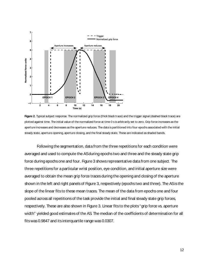
All forces and moments measured in the local sensor frames were transformed into the
common handle-fixed reference frame located at point P. For each trial in Part II of the study,
the trigger signal provided four time points: two indicating the starting of the motor (in two
directions), and two indicating its stopping. These time points were used to segment the data
for that trial into four epochs. Figure 2 illustrates the four epochs for a typical trial. It shows the
trigger signal (dashed black trace) and the normalized grip force (thick black trace) against time.
The first epoch was the initial steady state lasting between 1.5 and 0.5 s before the first trigger
(motor turned ON). The motor speed rose from zero to the prescribed speed over 2.5 s
(duration previously measured by Zatsiorsky et al. 2006), and therefore, the second epoch – the
opening of the aperture – started 3 s after the first trigger and lasted up to the second trigger
(motor turning OFF). Similarly, the third epoch was the closing of the aperture, and it started 3 s
after the third trigger (motor turning ON) and lasted up to the fourth trigger (motor turning
OFF). This provided a window of 6.6 ± 0.8 mm and 6.3 ± 0.9 mm (mean ± SD) for the second
(aperture opening) and third (aperture closing) epochs, respectively, for obtaining estimates of
AS. The total duration of the perturbation from the first to the fourth trigger signal was 12.4 ±
0.4 s (averages are across all trials). In previous studies, the window size used was up to 6.5 mm
(Zatsiorsky et al. 2006) and ≤ 7 mm (Van Doren, 1998). The final epoch was the steady state
starting 0.5 s after the last trigger and lasted 1.5 s.
12
Figure 2. Typical subject response. The normalized grip force (thick black trace) and the trigger signal (dashed black trace) are
plotted against time. The initial value of the normalized force at time 0 s is arbitrarily set to zero. Grip force increases as the
aperture increases and decreases as the aperture reduces. The data is partitioned into four epochs associated with the initial
steady state, aperture opening, aperture closing, and the final steady state. These are indicated as shaded bands.
Following the segmentation, data from the three repetitions for each condition were
averaged and used to compute the AS during epochs two and three and the steady state grip
force during epochs one and four. Figure 3 shows representative data from one subject. The
three repetitions for a particular wrist position, eye condition, and initial aperture size were
averaged to obtain the mean grip force traces during the opening and closing of the aperture
shown in the left and right panels of Figure 3, respectively (epochs two and three). The AS is the
slope of the linear fits to these mean traces. The mean of the data from epochs one and four
pooled across all repetitions of the task provide the initial and final steady state grip forces,
respectively. These are also shown in Figure 3. Linear fits to the plots “grip force vs. aperture
width” yielded good estimates of the AS. The median of the coefficients of determination for all
fits was 0.9847 and its interquartile range was 0.0307.

13
Figure 3. Computation of grip force and apparent stiffness (AS) for a representative subject. Data averages are across three
repetitions for a particular wrist position, eye condition, and initial aperture size. Left panel shows the initial steady-state grip
force (mean and SD) and the mean (black line) and SD (black band) of the grip force as the aperture increases from left to right.
The right panel shows the mean (black line) and SD (black band) of the grip force as the aperture decreases from left to right
and the final steady state grip force (mean and SD). The blue lines in each panel are the linear regression lines to the mean grip
forces. The slopes of these linear fits are the AS.
Unbalanced digit forces and moments
The components of the handle assembly move during the aperture-manipulation phase
of the experiment. This might lead to unbalanced forces and moments on the handle, which
implies movement of the handle. The net digit force, after adjusting for handle weight was
small indicating that the handle was stationary during the trials. The mean and standard
deviation (SD) of the magnitude of the sum of all finger forces and handle weight (the
manipulation force on the handle) was 0.63 ± 0.7 N with a maximum value of 1.6 N. These
unbalanced forces are considered small.
The net digit moment magnitude and the net digit moment along the handle-fixed Y-axis
MY (wrist pronation-supination) were analyzed in detail. A consistent, non-zero moment was
applied by the digits on the handle to counter the unbalanced external torque. Possible sources
of this external torque are the handle weight, since the handle CG is not located at point P
(Figure 1), and cables of the sensors and the laser. In particular, the digits apply a consistent

14
supination moment (MY) of about 50 Nmm on the handle. The detailed analysis is provided in
Appendix A.
Statistics
Most data are presented as means and standard deviations (SD). The AS values were
analyzed with a 4-way repeated measures ANOVA with factors Ramp (aperture opening and
aperture closing), Eye-condition (open and closed), Initial-aperture (small and large), and Wrist-
position (5 levels). Similarly, the steady-state grip force values were analyzed with four-way
repeated-measures ANOVA with factors Perturbation (before and after), Eye-condition, Initial-
aperture, and Wrist-position. All data were pooled across subjects. All statistics were performed
using an a-level of 0.05. Mauchly’s sphericity tests were performed to verify the validity of
using repeated-measures ANOVA. The Greenhouse-Geisser adjustment to the degrees-of-
freedom was applied whenever departure from sphericity was observed. Significant effects of
ANOVA were further explored using pairwise comparisons with Bonferroni corrections. All
possible pair-wise contrasts were conducted. All statistics were performed with SPSS statistical
software.
The 4-way ANOVA for AS revealed a significant 4-way interaction effect (p < 0.05).
Instead of interpreting this interaction, we pooled the data across the Ramp factor, which failed
to show a significant main effect (p = 0.429), by taking the arithmetic mean of the AS values in
the aperture opening and closing conditions. A 3-way repeated-measures ANOVA was then
performed on the pooled AS data with the remaining three factors. The results of the 3-way
ANOVA are reported below.

15
RESULTS Apparent grip stiffness
Changes in the grip aperture produced by the motor led to grip force (FG) modulation.
An increase in the aperture width led to an increase in FG, whereas a decrease in the aperture
width led to a drop in FG (illustrated in Fig. 3). The apparent stiffness (AS) computed as the
slope of the FG dependence on aperture width showed a weak dependence on wrist position:
While the effect of Wrist-position was significant (F(1.84,16.63) = 7.69; p < 0.01), pairwise contrasts
confirmed only a significant difference between the most flexed wrist position and the
neighboring position (5.5±2.7 N/cm vs. 4.3±1.8 N/cm for positions P1 and P2 in Fig. 4 (A)). No
significant differences across the four wrist positions from P2 to P5 were observed.
Performance of the task with eyes closed was associated with deviations of the handle
from the vertical (on average, 10° ± 8°), while the handle was sufficiently close to the vertical
within the error margin provided by the spirit level (2° ± 0.8°) in the eyes-open condition
(repeated measures t-test: t(9) = 11.151; p < 0.01). When the subjects performed the task with
eyes open the AS was larger than with eyes closed (5.4±2.4 N/cm vs. 4.0±1.8 N/cm, F(1,9) =
12.22; p < 0.01). AS also depended on the initial aperture: It was larger for the wider aperture
as compared to the smaller one (5.3±2.3 N/cm vs. 4.2±2.0 N/cm, F(1,9) = 36.19; p < 0.01). The
last two effects were uniform across all wrist positions, as seen in Figures 4(B) and (C).

16
Figure 4. Apparent stiffness mean and SD across various conditions. Wrist positions are labeled from P1 to P5 ranging from
flexion to extension in that order. Significant differences are indicated with a star (*).
Steady-state grip force
The ordered increase-decrease change in the grip aperture led to a change in FG: The
steady-state FG value was significantly greater before the perturbation than after (8.7±2.2 N vs.
6.6±2.0 N; F(1,9) = 31.64; p < 0.01). This effect was uniform across all wrist position (Fig. 5(B)).
The subjects applied higher FG in conditions with the larger grip aperture as compared to those
with the smaller aperture (8.1±2.5 N vs. 7.2±2.2 N; F(1,9) = 113.72; p < 0.01); see Fig. 5(C). They
also had a tendency to apply stronger FG when wrist position was close to one of the limits of
the wrist range of motion (F(1.259,11.327) = 6.963; p < 0.05). Pairwise contrasts confirmed
significantly larger grip force at the extreme extension posture (P5 in Fig. 5 (A)) compared to its
neighboring postures (8.0±2.3 N at P5 compared to 7.2±1.9 N at P4 and 6.9±1.7 N at P3). At the
extreme flexion posture (P1), FG was higher than at the neighboring postures (P2 and P3, see
Fig. 5 (A)), but these differences did not reach statistical significance. Finally, FG for the eyes-

17
closed condition was smaller than that for the eyes-open condition (7.4±2.3 N vs. 7.9±2.5 N),
but this difference did not reach statistical significance (F(1,9) = 3.376; p = 0.099).
There were also significant two-way interactions: Initial-aperture × Perturbation (F(1,9) =
9.89; p < 0.05), Eye-condition × Initial-aperture (F(1,9) = 7.99; p < 0.05), Perturbation × Wrist-
position (F(2.21,19.89) = 6.41; p < 0.01), and Eye-condition × Wrist-position (F(4,36) = 3.96; p < 0.01).
The first interaction results from the fact that the drop in FG after the perturbation was larger
for the large initial aperture size. The second interaction effect appears because the effect of
eye condition on grip force (higher FG for the eyes-open condition) was evident only for the
small initial aperture. The third interaction reflects the fact that FG was more uniform across
wrist positions after perturbation than before the perturbation. Finally, Eye-condition had
minimal effect on FG only in wrist position P2; this yielded the last interaction effect.
It is well-known that a slow drop in isometric force occurs when the subject’s visual
feedback of that force is removed, even as the subjects try to keep the force constant (Slifkin et
al. 2000; Vaillancourt and Russell 2002; Baweja et al. 2009). In the present study, FG was not
expected to drop, for example to avoid slippage of the object. To test this, two subjects
performed a control trial where they held the handle for 35 s while no change in grip aperture
took place. Across all wrist positions and aperture sizes, the subjects showed, on average, a net
drop in FG of 0.6 N and 0.4 N, which is substantially lower than the average drop in FG across the
main experimental series: 2.2 ± 1.2 N.

18
Figure 5. The steady state grip force mean and SD for various conditions. Wrist positions are labeled from P1 to P5 ranging from
flexion to extension in that order. Significant differences are indicated with a star (*)

19
DISCUSSION
The first hypothesis formulated in the Introduction – grip apparent stiffness (AS) would vary
with wrist position – received partial support. While AS varied, this variation was limited to
postures in a close proximity to the fully flexed wrist position. This observation is consistent
with our earlier study (Ambike et al. 2013) wherein the “natural grip force” for the extreme
wrist flexion was higher than for all other wrist positions. Other wrist positions had no effect on
AS; so, for those positions Hypothesis-1 is rejected by the data.
Hypothesis-2 –AS increases with initial aperture size – is supported by the data. The
larger initial grip aperture resulted in larger AS values. This result is in contrast to the findings of
(Van Doren 1998) who reported only slight changes in AS with aperture size. This may be
explained by the fact that the initial apertures used in this work were larger than those used by
Van Doren, 8.5 and 9.5 cm compared to the maximum aperture of 6.5 cm in Van Doren’s study.
Hypothesis-3 is also supported by the data. Absence of visual feedback on the grip force
during steady-state trials with no changes in the grip geometry resulted in some drop in grip
force (Δ(FG) < 1 N, control trials). However, we observed a consistent and larger drop in grip
force after the cycle of handle expansion-contraction of similar duration (average Δ(FG): 2.1 N).
These results are consistent with earlier reports on a drop in the force produced in isometric
accurate force production tasks after visual feedback had been turned off (Slifkin et al. 2000;
Vaillancourt and Russell 2002; Baweja et al. 2009). While in the cited studies, force level was
instructed but served no ecological purpose, in the current study FG had to be above a certain
value to prevent object slip. The potentially dangerous drop in FG suggests that the underlying
mechanism is powerful and can override, at least partly, safety constraints imposed by the
friction conditions at the digit-object interface.
With respect to the exploratory goal, we observed that AS increased in conditions when
the subjects were required to maintain handle orientation. The possible role of visual feedback
is discussed below.

20
Grip force via referent aperture control
One of the least expected results of the current study is the relative independence of AS
of the length of extrinsic hand muscles. Wrist joint rotation over most of its range produced
little change in AS despite the large changes in the length of the extrinsic digit flexors (FDP and
FPL). The estimated FDP tendon excursions over ± 50° wrist flexion-extension from the nominal
position (the palm aligned with the forearm) ranges from 2.39 cm for the little finger to 2.18 cm
for the middle finger (Lemay and Crago 1996; Brand and Hollister 1999; Paclet 2010). These
observations are congruent with the constancy of “natural FG” over the range of wrist flexion-
extension positions (Ambike et al. 2013). Both groups of observations are in contrast to the
strong modulation of the maximal FG throughout the same range of wrist positions (Ambike et
al. 2013), which is in line with the classic muscle force-length curve (McMahon 1984).
We analyze these results within the referent-configuration (RC) hypothesis (Feldman
and Levin 1996; Feldman 2011) which is an extension of the classical equilibrium point
hypothesis (Feldman 1986) to multi-effector actions. The RC hypothesis assumes that the
central nervous system uses changes in neural variables that, given the external force field,
produce changes in the body (effector) RC. Referent configurations are commonly not
accessible to the effector because of anatomical and external constraints. As a result,
equilibrium states are observed with non-zero muscle activations and active forces produced
on the environment.
According to the RC hypothesis (Pilon et al. 2007), grip forces emerge as muscles are
activated in proportion to the difference between the referent coordinates for the digit tips and
their actual coordinates. Assuming that the resultant force acting normal to the digit-handle
contact surface is zero, the two referent coordinates – for the thumb and for the four fingers
combined – may be united into a single variable, the referent aperture (however, see discussion
below). In a linear approximation, FG magnitude is related to the difference between the
referent and actual apertures by the AS. Assume now that, at a control level, a certain referent
aperture is specified in the handle-fixed reference frame. Since the actual aperture does not
depend on wrist angle, over the range of wrist flexion-extension, AS defines FG unambiguously.
Our results of constant AS throughout most of wrist range of motion and higher AS at the

21
extreme wrist flexion correspond well to the earlier report on constant FG throughout the wrist
motion with somewhat higher FG at the extreme wrist flexion (Ambike et al. 2013).
Specifying referent values for the task-relevant variables in an object-fixed reference
frame may simplify object manipulation. An intuitive analogy is as follows. Imagine a fiddler
playing music with the fiddle in various configurations relative to the body, e.g., over the
shoulder or even behind the back. The claim here is that the fiddler’s central nervous system
learned to control the task using referent coordinates of various fingers in a reference frame
fixed to the fiddle rather than to the body or to the external world. Then, the position of the
fiddle relative to the body becomes irrelevant for the successful execution of the task.
How many variables define the referent configuration?
For static prehension tasks, the referent aperture may be visualized as shown in Figure
6(A). If the digits rest on parallel surfaces, the aperture is viewed as two lines parallel to the
digit-object contact surfaces, displaced by equal amounts from those surfaces. The magnitudes
of the forces at the contact surfaces are equal and are given by F1 = –F2 = AS(Qa-Ra)/2, where
Qa is the object-defined actual aperture, and Ra is the central-nervous-system-specified
referent aperture. Such schemes are implied or explicitly depicted in literature (Pilon et al.
2007; Latash et al. 2010). This picture suggests that: (a) the relation between the generated
force and the differences between the current and referent positions is the same for the
opposing digits, (b) the AS of the opposing digits is the same, and (c) a single variable Ra is
sufficient for specifying FG.
In this study, we found that (1) symmetrical changes in actual configurations of the
thumb and VF induced symmetrical changes in their respective forces (since unbalanced forces
were small), and (2) these changes were linearly related to changes in the aperture produced
by the motor. This suggests that the statements (a) and (b) above are reasonable. However, in
the case of multi-finger prismatic grasp, Zatsiorsky et al. (2006) showed that, although the AS
values for the thumb and VF were similar, those for individual digits were different. Therefore,
the AS of the VF may be viewed as associated with four ‘digit-springs’ acting in parallel: ASTH =
ASVF = SASi, where i = {index, middle, ring, little}, when the gripping surface is a plane. It is

22
possible that the preferred distribution of the referent coordinate for the VF across the four
actual fingers (see Latash et al. 2010) reflects the different AS values for the fingers.
There is some debate regarding the number of variables that define object gripping. For
example, Smeets & Brenner (1999) suggest that gripping is akin to two independent pointing
actions of opposing digits rather than a single change in hand aperture. On the other hand,
Latash et al. (2010) suggest a more complete set of referent coordinates (Fig 6 (B)) for static
object grasping in a gravity field and in the presence of external torques. In this scheme, hand
control in a planar task may be described with referent values for three variables, referent
aperture (Ra), referent vertical coordinate (RGY), and referent angle (Rq) with respect to the
vertical (Y axis in Fig. 6). The force of digit i is the vector sum of forces arising due to (a) the
difference between the referent and actual apertures (Fia) along the X axis, (b) the difference
between the referent and actual vertical coordinates (load resisting force FiG), and (c) the
difference between the vertical orientation of the object and its referent orientation (external
torque-resisting moment of force via vertical forces Fiq). This depiction assumes point contacts
(Mason and Salisbury 1985).
During object manipulation, however, it is evident that digit forces are unequal so that
the resultant manipulation force creates object motion. Slota et al. (2011) show that the
unequal thumb and VF normal forces can be predicted from the object’s acceleration; a non-
trivial result since only the unbalanced normal force is mechanically related to object
acceleration. Two plausible ways of extending the referent coordinate idea to incorporate
object manipulation are illustrated in Figures 6 (C) and (D). First, object manipulation in the
vertical direction and object rotation is achieved by manipulating the referent coordinates RGY
and Rq, respectively. Manipulation in the horizontal direction (more generally, in the direction
of the digit normal forces) can be achieved by introducing another referent variable. In the first
scenario, the referent aperture remains stationary relative the object, and the referent
coordinate RGY shifts while maintaining its vertical distance from the actual object center of
gravity (CG). The additional reference coordinate is RGX, and it generates oblique digit forces as
shown in Figure 6(C). The second possibility is that the referent coordinate RGY is unchanged
relative to the object, and the referent aperture center shifts to a new location defined by RGX.

23
Note that here, digit 1 pushes against the object, and the object pushes against digit 2, so the
normal forces measured at both the digit-object interfaces can point into the object. Since
static equilibrium is a special case of object-grasp mechanics, it is reasonable to assume that at
least four referent variables are necessary to describe planar object-grasp mechanics. Whether
these speculations, or another set of four referent coordinates explain the findings of Slota et
al. (2011), remains to be seen. Note that the actual RC dimensionality may be higher because it
may include parameters that define muscle co-activation which have no or little effect on the
net values of the mechanical variables.
Figure 6. Referent apertures and the mechanism of grip force generation. Figure 6(A) depicts the simplest case wherein two
digits statically balance the object without applying any moment. Figure 6(B) depicts a possible way in which the referent
coordinates can be modulated to counter object weight w and external torque acting on the object. Figures (C) and (D) depict
two possible ways in which changes in four referent coordinates can produce movement of the object to the right. In all cases,
the forces measured at the digit-object interface are the vector sum of the digit forces resulting from the prescribed values for
all four referent coordinates. Assume zero external torque for simplicity. So, Rq = 0.

24
Violations of equifinality of grip force
The significant drop in FG after an “expansion-contraction” cycle of the grip aperture has
been an unexpected finding. Ensuring adequate safety margin has frequently been viewed as
one of the most powerful criteria that define FG across conditions (Johansson and Westling
1984; Flanagan and Wing 1993; Flanagan and Tresilian 1994). In our experiment, a single 12-s
cycle of the aperture width change led to a 25% drop in FG. The safety margin for digit i (SMi) is
defined as SMi = (FN – FT/m)/FN, where FN and FT are the normal and the vertical tangential
forces of digit i, respectively, and m is the friction coefficient (Westling and Johansson 1984;
Burstedt et al. 1999; Zhang et al. 2011). The safety margin (SM) for the grip is min(SMi), where i
= {thumb, index, middle, ring, little}. During our study, the SM dropped from 59% to 52% due to
the aperture perturbation (median values). There must be a powerful factor that led to such a
major reduction of the safety margin.
Fatigue was unlikely to be such a factor. First, each trial lasted for about 30 s and
involved modest grip forces (typically < 15 N). Earlier studies of fatigue (Singh et al. 2012)
suggest that much higher forces are needed to produce measurable fatigue of flexor muscles
that contribute to the grip force. Besides, control trials on two subjects showed a much lower
drop in FG over the same time period when no change in the aperture occurred.
A drop in FG at the final state with the same aperture suggests that the referent
aperture changed despite (or perhaps because of) the instruction to the subjects “not to
interfere”. This could happen due to the hypothetical back-coupling between referent and
actual configurations proposed in the model of (Martin et al. 2009). Within that model, RC
attracts the actual body configuration resulting in non-zero force production if motion of the
actual configuration is impeded. However, if actual configuration stays far from RC for a long
time interval, RC starts to be attracted to the current actual configuration.
This phenomenon can account for the earlier reports of a relatively slow force drop in
isometric force production tasks when visual control is unavailable (Slifkin et al. 2000;
Vaillancourt and Russell 2002; Baweja et al. 2009). It can also account for the drop in FG in the
current study. Indeed, the aperture expansion and contraction were relatively slow. During that
time interval, RC could move towards the actual configuration. This RC motion was safe since

25
the difference between RC and the actual configuration remained large. However, when the
actual configuration returned to its initial value, the RC change was reflected in the rather large
drop in FG. It is feasible that the strength of the back-coupling depends on the difference
between the actual configuration and RC. In this case, the increase in the actual aperture with
the handle expansion accelerated the process of RC drift and led to much larger drop in FG as
compared to the control trials.
There is also a possibility that the changes in the handle width were accompanied by
changes in the RC component affecting muscle co-contraction. Note that changes in this so-
called co-activation command can lead to changes in net forces if the external load is not zero
(Feldman 1986; Latash 1992). The current data set does not allow distinction between the
sources of changes in the grip force following the transient change in the handle width.
The RC drift suggests that the subject was unable ‘not to intervene’ as required by the
instruction. This factor may be viewed as a limitation of the study or as its important feature.
We studied the natural behavior of the hand under the instruction to the subjects ‘not to
intervene voluntarily’. The inability of the subjects to follow this instruction could be partly due
to the mentioned back-coupling between the actual and referent configurations and partly to
the implicit constraint of not moving and not dropping the hand-held object during handle size
changes.
Effects of vision on grip force and its changes The results obtained in trials with eyes open and eyes closed were qualitatively similar,
however, the changes in grip force were significantly larger when the subjects could watch the
handle. It is possible that higher AS values were due to small adjustments in grip force to keep
the handle orientation vertical during the imposed changes in grip aperture. Since the handle
was not perfectly symmetrical and there was a residual digit moment (see Appendix A),
changes in the normal forces could lead to violation of the handle orientation requirement, in
particular because of the changes in the lever arms for the vertical tangential forces. Earlier
studies have shown so-called chain effects (Gao et al. 2005; Aoki et al. 2007; Zatsiorsky and
Latash 2008) when a change in only a subset of digit forces and/or other features of the task

26
(such as handle geometry and friction conditions) lead to changes in many other variables
caused by the static constraints.
In our experiment, the unbalanced moments were small and the subjects showed
relatively minor handle deviations from the vertical, even in the closed-eyes trials. However,
when they watched the handle, these small deviations were visible on the spirit level, and the
subjects could introduce corrections that could, in particular, involve changes in the normal grip
forces.
There are two main conclusions of this study. First, the results allow for a rather simple
analysis of the control of object manipulation using the language of RCs, despite the complex
anatomical structure of the hand. The seeming robustness of the grip apparent stiffness to
substantial changes in wrist position and extrinsic hand muscle lengths may allow for some
decoupling in the control of the wrist action from grip force production. A few referent
variables can plausibly account for hand-object statics as well as dynamics. Secondly, this study
suggests the presence of an underlying process functioning at a distinct time scale. The
relatively slow drift of the referent configuration towards the actual one was invoked to explain
the steady-state grip force characteristics. Indeed, it remains to be seen if such processes are
present in other movements and body segments, and what purposes they could serve.
ACKNOWLEDGMENTS
We thank Ms. Kelly Ann Carey for her assistance in data collection. The present work was
supported by NIH grants NS-035032 and AR-048563.

27
REFERENCES
Ambike SS, Paclet F, Latash ML, Zatsiorsky VM (2013) Grip-force modulation in multi-finger prehension during wrist flexion and extension. Exp Brain Res 227:509–22. doi:10.1007/s00221-013-3527-z
Aoki T, Latash ML, Zatsiorsky VM (2007) Adjustments to local friction in multifinger prehension. J Mot Behav 39:276–90. doi:10.3200/JMBR.39.4.276-290
Baweja HS, Patel BK, Martinkewiz JD, Vu J, Christou EA (2009) Removal of visual feedback alters muscle activity and reduces force variability during constant isometric contractions. Exp Brain Res 197: 35–47. doi:10.1007/s00221-009-1883-5
Bernstein N (1967) The co-ordination and regulation of movements. Oxford: Pergamon
Brand P, Hollister A (1999) Clinical mechanics of the hand. St. Louis: Mosby Year Book
Burstedt MKO, Flanagan JR, Johansson RS (1999) Control of Grasp Stability in Humans Under Different Frictional Conditions During Multidigit Manipulation. J Neurophysiol 82:2393–2405
Feldman A (1966) Functional tuning of the nervous system with control of movement of maintainence of a steady posture - II Controllable parameters of the muscle. Biophysika 11:565–578
Feldman AG (1986) Once more for the equilibrium-point hypothesis (lambda-model) for motor control. J Mot Behav 18:17–54
Feldman AG (2011) Space and time in the context of equilibrium-point theory. Wiley Cognitive Sciences 2:287–304
Feldman AG, Levin MF (1996) Grasping cerebellar function depends on our understanding the principles of sensorimotor integration: The frame of reference hypothesis. Behav Brain Sci 19:442–445
Feldman A, Orlovsky G (1972) The influence of different descending systems on the tonic stretch reflex in the cat. Exp Neurol 37:481-494
Flanagan J, Tresilian J (1994) Grip-load force coupling: a general control strategy for transporting objects. J Exp Psych: Human Perception and Performance 20:944–957
Flanagan J, Wing A (1993) Modulation of grip force with load force during point-to-point arm movements. Exp Brain Res 95:131–143

28
Gao F, Latash ML, Zatsiorsky VM (2005) Internal forces during object manipulation. Exp Brain Res 165:69–83
Jaric S, Collins JJ, Marwaha R, Russell E (2006) Interlimb and within limb force coordination in static bimanual manipulation task. Exp Brain Res 168:88–97. doi:10.1007/s00221-005-0070-6
Johansson RS, Westling G (1984) Roles of glabrous skin receptors and sensorimotor memory in automatic control of precision grip when lifting rougher or more slippery objects. Exp Brain Res 56:550–564
Kerr J, Roth B (1986) Analysis of Multifingered Hands. Int J Robot Res 4:3–17
Latash ML (1992) Independent control of joint stiffness in the framework of the equilibrium- point hypothesis. Biol Cybern 67:377-384
Latash ML, Friedman J, Kim SW, Feldman AG, Zatsiorsky VM (2010) Prehension synergies and control with referent hand configurations. Exp Brain Res 202:213–229. doi:10.1007/s00221-009-2128-3
Latash ML, Zatsiorsky VM (1993) Joint stiffness: Myth or reality? Human Movement Sci 12:653–692
Lemay MA, Crago PE (1996) A dynamic model for simulating movements of the elbow, forearm, an wrist. J Biomech 29:1319–30
Martin V, Scholz JP, Schöner G (2009) Redundancy, self-motion, and motor control. Neural computation 21:1371–414. doi:10.1162/neco.2008.01-08-698
Mason M, Salisbury J (1985) Robot Hands and the Mechanics of Manipulation. Cambridge: The MIT Press
Matthews P (1959) A study of certain factors influencing the stretch reflex of the decerebrate cat. J Physiol 147:547–564
McMahon T (1984) Muscles, Reflexes, and Locomotion. Princeton University Press
Murray RM, Li Z, Sastry SS (1994) A Mathematical Introduction to Robotic Manipulation. Boca Raton: CRC Press
Paclet F (2010) Analyse Biomécanique Des Transferts Tendineux De La Main (Technique Tsugé). Dissertation, Universite Joseph Fourier

29
Paclet F, Ambike S, Zatsiorsky VM, Latash ML (in press). Enslaving in a serial chain: Interactions between grip force and hand force in isometric conditions. Exp Brain Res. doi:10.1007/s00221-013-3787-7
Parikh PJ, Cole KJ (2012) Handling objects in old age: forces and moments acting on the object. J App Physiol 112:1095–104. doi:10.1152/japplphysiol.01385.2011
Pilon J-F, De Serres SJ, Feldman AG (2007) Threshold position control of arm movement with anticipatory increase in grip force. Exp Brain Res 181:49–67
Platzer W (2004) Color Atlas of Human Anatomy, Locomotor System. New York: Thieme
Savescu A, Latash ML, Zatsiorsky VM (2008) A technique to determine friction at the finger tips. J Appl Biomech 24:43–50
Singh T, Zatsiorsky VM, Latash ML (2012) Effects of fatigue on synergies in a hierarchical system. Human Movement Sci 31:1379–98. doi:10.1016/j.humov.2012.06.008
Slifkin AB, Vaillancourt DE, Newell KM (2000) Intermittency in the control of continuous force production. J Neurophysiol, 84:1708–1718
Slota GP, Latash ML, Zatsiorsky VM (2011) Grip forces during object manipulation: experiment, mathematical model, and validation. Exp Brain Res 213:125–39
Smeets J, Brenner E (1999) A new view on grasping. Mot Control 3:237–271
Vaillancourt DE, Russell DM (2002) Temporal capacity of short-term visuomotor memory in continuous force production. Exp Brain Res 145:275–85. doi:10.1007/s00221-002-1081-1
Van Doren CL (1998) Grasp stiffness as a function of grasp force and finger span. Mot control 2:352–78
Xu Y, Terekhov AV, Latash ML, Zatsiorsky VM (2012) Forces and moments generated by the human arm: variability and control. Exp Brain Res, 223:159–75. doi:10.1007/s00221-012-3235-0
Yoshikawa T, Nagai K (1991) Manipulating and Grasping Forces in Manipulation by Multifingered Robot Hands. IEEE Trans Robot Autom 7:67–77
Zatsiorsky VM, Latash ML (2008) Multi-finger Prehension: An Overview. J Mot Behav, 40:446–476
Zatsiorsky VM (2002) Kinetics of Human Movement. Human Kinetics

30
Zatsiorsky VM, Gao F, Latash ML (2006) Prehension stability: experiments with expanding and contracting handle. J. Neurophysiol 95:2513–29. doi:10.1152/jn.00839.2005
Zhang W, Gordon AM, McIsaac TL, Santello M (2011) Within-trial modulation of multi-digit forces to friction. Exp Brain Res 211:17–26. doi:10.1007/s00221-011-2628-9

31
APPENDIX A Statistical analysis of the unbalanced digit moments
For each trial the resultant moment of all digits was computed in the handle-fixed
reference frame located at point P (Figure 1). The moment profiles were averaged across the
three repetitions for each condition. We analyzed the moment in the grasp plane (MY) and the
magnitude of the moment vector (|M|). From the averaged moment trajectory for each
condition, the following six MY and |M| values were selected: (1) initial steady-state values
(IniSS), (2) the maximum value during the aperture opening phase (Max-Open), (3) the
minimum value during the aperture opening phase (Min-Open), (4) the maximum value during
the aperture closing phase (Max-Close), (5) the minimum value during the aperture closing
phase (Min-Close), and (6) the final steady-state value (FinSS). Data were pooled across subjects
and conditions (wrist position, eyes open/closed, initial aperture size) and subjected to a one-
way ANOVA with the factor Epoch (6 levels). Pair-wise comparisons were done using Bonferroni
corrections.
Figure 7. The mean and SD for the unbalanced moment about the handle-fixed Y axis MY (black bars) and the magnitude of the
net unbalanced moment |M| (white bars) are shown. The following six moments are analyzed: (1) initial steady-state (IniSS), (2)
the maximum during the aperture opening phase (Max Open), (3) the minimum during the aperture opening phase (Min Open),
(4) the maximum during the aperture closing phase (Max Close), (5) the minimum during the aperture closing phase (Min
Close), and (6) the final steady-state (FinSS).

32
The results are shown in Figure 7. The ANOVA showed a significant effect of Epoch for
both MY (F(5,1094) = 37.104, p < 0.01) and |M| (F(5,1094) = 31.395; p < 0.01), and several pair-wise
comparisons were significant. We summarize the main observations below.
1. The initial and final steady-states values were the same for both variables.
2. The moments dropped during the aperture-opening epoch from their initial steady-state
values.
3. The moments recovered during the aperture-closing epoch.
4. These changes, although significant, were small. The largest differences between the
marginal means for any pair were: -33.26 Nmm for MY and 19.9 Nmm for |M|.
5. The overall means (SD) for the two variables were: -50.23 ± 28.2 Nmm for MY and 60.91
± 20.9 Nmm for |M|.
We conclude that a consistent, non-zero moment was applied by the digits on the handle to
counter the unbalanced external torque. Possible sources of this external torque are the handle
weight, since the handle CG is not located at point P (Figure 1), and cables of the sensors and
the laser. In particular, the digits applied a consistent supination moment of about 50 Nmm on
the handle.