Embed Size (px)
Citation preview

FACILITY DESIGN STANDARDS
Revised March 2013

i
DIVISION OF FACILITIES MANAGEMENT
FACILITY DESIGN STANDARDS
TABLE OF CONTENTS
INTRODUCTION
PROJECT PLANNING AND DESIGN PROCEDURES
PROCUREMENT AND CONTRACTING REQUIREMENTS (DIVISION 00)
SPECIFICATION AND DESIGN STANDARDS
GENERAL REQUIREMENTS (DIVISION 01)
DIVISION 01 GENERAL REQUIREMENTS
FACILITY CONSTRUCTION (DIVISION 02 – 19)
DIVISION 02 EXISTING CONDITIONS
DIVISION 03 CONCRETE
DIVISION 04 MASONRY
DIVISION 05 METALS
DIVISION 06 WOOD AND PLASTICS
DIVISION 07 THERMAL AND MOISTURE PROTECTION
DIVISION 08 OPENINGS
DIVISION 09 FINISHES
DIVISION 10 SPECIALTIES
DIVISION 11 EQUIPMENT
DIVISION 12 FURNISHINGS
DIVISION 14 CONVEYING EQUIPMENT
FACILITY SERVICES (DIVISION 20-29)
DIVISION 21 FIRE SUPPRESSION

ii
DIVISION 22 PLUMBING
DIVISION 23 HEATING, VENTILATION AND AIR
CONDITIONING (HVAC)
DIVISION 26 ELECTRICAL
DIVISION 27 COMMUNICATIONS
DIVISION 28 ELECRONIC SAFETY AND SECURITY
SITE AND INFRASTRUCTURE (DIVISION 30-39)
DIVISION 31 EARTHWORK
DIVISION 32 EXTERIOR IMPROVEMENTS
DIVISION 33 UTILITIES
APPENDIX A OFFICE SPACE STANDARDS
APPENDIX B OFF-STREET PARKING STANDARDS
APPENDIX C DFM PROTOTYPE OFFICE BUILDING
iii
INTRODUCTION
SCOPE
This standard is a guide for the design of typical State of Delaware facilities. Compliance is
mandatory for Division of Facilities Management (DFM) projects and other projects as requested
by the client and subsequently directed by the DFM Project Manager in writing. Deviations
from this standard shall be requested in writing by the design professional.
DESIGN CONFLICTS
Notify the DFM Project Manager, in writing, of any and all conflicts associated with the use of
this standard and/or requirements that are contrary to current design practice.
UPDATES
This standard will be updated on a regular basis. Use the standard in effect at the time of A/E
contract execution.

iv
PROJECT PLANNING AND DESIGN PROCEDURES
1. Design progress meetings will be held monthly unless the DFM Project Manager and the
A/E mutually decide otherwise. Meeting minutes will be taken by the architect at all
design meetings. These minutes will be typed and distributed within three business days
of the meeting date.
2. Design procedures will follow requirements outlined in AIA Document B101 Owner and
Architect Agreement. Contact the Chief of Engineering and Operations for the specific
procedures to be followed for the project.
3. Final Plan Signatures - A/E to provide two sets of final plans. Building client shall sign
one set and return to DFM Project Manager and keep one set for their use during
construction.
4. A/E to consult with DFM Project Manager on any special graphics (plans, color
elevations or other graphics) required by DFM or the building client for use during any
legislative, municipal or other budget hearing.
5. Provide summary narrative to DFM Project Manager prior to the preconstruction
meeting. Review submittal status at each construction progress meeting.
6. Utilize DFM drawing standards during design and construction activities.

v
DIVISION 00 – PROCUREMENT AND CONTRACTING REQUIREMENTS
1. Incorporate the specifications listed below into the project. See DFM website
(http://dfm.delaware.gov)
00 01 01 Project Title Page
00 01 10 Table of Contents
00 01 15 List of Drawing Sheets
00 11 16 Invitation to Bid
00 21 13 Instructions to Bidders
00 41 13 Bid Form
00 43 13 Bid Bond
00 43 43 Delaware Prevailing Wage Rates (project specific)
00 52 13 Standard Form of Agreement Between Owner and Contractor
00 54 13 Supplement to Agreement Between Owner and Contractor
00 61 13.13 Performance Bond
00 61 13.16 Payment Bond
00 72 13 General Conditions to the Contract
00 73 13 Supplementary General Conditions
00 81 13 General Requirements
1
SPECIFICATION AND DESIGN STANDARDS
DIVISION 01 - GENERAL REQUIREMENTS
Section 01 41 13 Codes and Standards
1. The building code adopted by local municipal government (county, city or town) will be
complied with unless other stringent design criteria are utilized. If there are any
questions, consult with the DFM Project Manager for resolution.
2. All required regulatory approvals (local site plan, State Fire Marshall, DelDOT, DNREC,
etc.) shall be obtained PRIOR TO bid advertisement.
3. Review with the Project Manager what submittals are required for final close out of the
project, i.e., archival quality “as-builts,” CADD “as-builts,” CD ROMs, electronic
specifications, bound maintenance manuals, etc.
Section 01 50 00 Temporary Facilities and Controls
1. Review requirements for temporary utilities (electric, heat, potable water, toilets, etc.),
storage, office space and signage with the DFM Project Manager. Clearly state in the
project specifications WHO is responsible for providing these facilities. Include in
section guidelines that the contractor is responsible for the condition and maintenance of
all building systems if utilized during construction prior to substantial completion of the
work.
2. Areas to be used for stockpiling of materials and equipment to be designated by DFM
and clearly indicated on the plans.
3. Building utility shutdowns for existing facilities should be reviewed with building
occupant and maintenance personnel prior to bidding. The specific time of day (after
regular work hours, weekends) and duration (number of hours) should be indicated in the
specifications.
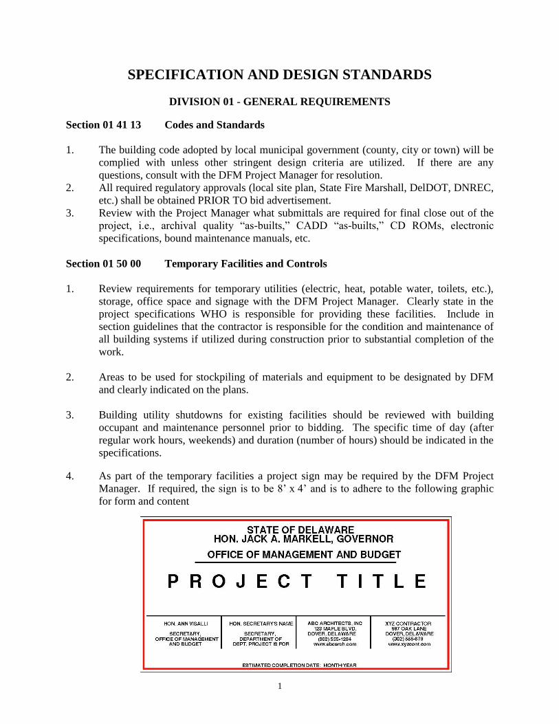
4. As part of the temporary facilities a project sign may be required by the DFM Project
Manager. If required, the sign is to be 8’ x 4’ and is to adhere to the following graphic
for form and content

2
Section 01 74 19 Construction Waste Management and Disposal
1. Incorporate DFM Specification 01 74 19, Construction Waste Management and Disposal.
Section 01 78 23 Operations and Maintenance Data
1. Provide for three copies of manufacturer’s information for all building components,
assemblies, subassemblies, attachments and accessories. Information to be included
consists of the following: operating instructions, safety precautions, service
requirements, preventative maintenance, lubrication data, corrective maintenance,
troubleshooting/diagnostic techniques, wiring diagrams and controls and spare
parts/supplies.
2. Provide for training and indoctrination of maintenance personnel. Review specific
requirements with the Project Manager and facility owner’s maintenance personnel.
State number of hours required and how many sessions to be provided. Training to be
provided during regular business hours unless additional sessions are necessary for
evening/night shift personnel. In most cases, the contractor should videotape the training,
with the contractor providing all necessary equipment, materials and personnel. An
attendance sheet shall be completed by the contractor for all training sessions, with a
copy provided to the DFM Project Manager.
3. Operation and maintenance manuals shall be received prior to substantial completion and
before training is conducted.
Section 01 78 39 Project Record Documents
1. As-built drawings shall be maintained by the contractor on a weekly basis. The A/E shall
review as-builts at regular progress meetings to ensure compliance by the contractor. As-
builts to be submitted for review/approval by the A/E a maximum of 30 days after
completion of the project.
Section 01 80 00 Performance Requirements
1. The design will be accomplished in compliance with current codes at the onset of the
design contract.
2. Live loads are specified by the applicable required building code. Minimum acceptable
office floor live load is 60 psf.
3. Confirm all load criteria and any special design program requirements with the DFM
Project Manager prior to proceeding with Schematic Design.
4. Isolate elevator equipment room floors and walls for sound attenuation. Locate
machinery spaces away from offices, waiting/reception and conference areas. Provide
sound attenuation insulation to minimize noise as required.
5. On projects with low-sloped roofing systems, the slope should be incorporated in the
structure whenever possible.

3
6. Floor plans shall show the location, type and extent of all materials, equipment and
fixtures. Enlarged detail floor plans of specialized areas (toilet rooms, kitchens,
laboratories, shops, mechanical rooms, etc.) shall be drawn.
7. Provide elevations of all walls for toilet rooms noting mounting heights of all accessories
and fixtures.
8. New construction and major reconstruction projects shall be designed to LEED Silver
requirements as a minimum.
Section 01 91 13 Building Commissioning
1. Commissioning – A systematic process of ensuring that all building systems perform
interactively according to the design intent and the owner’s operational needs – shall be
incorporated where:
a) New construction over 50,000 s.f.
b) Renovated/replaced equipment/systems in buildings over 50,000 s.f.
c) As requested by DFM Project Manager.
2. The commissioning process does not reduce the responsibility of the system designers or
installing contractors to provide a finished and fully functional product.
3. Commissioning of large or technically complicated projects shall begin at the pre-
programming stage and last until the building has been occupied for four full seasons.
4. For large or technically complicated projects, a formal commissioning team shall be
established and consist of the following:
a) Commissioning authority
b) DFM Project Manager
c) Client maintenance representative
d) Representative of CM and/or GC
e) Representative of A/E
f) Mechanical contractor
g) Electrical contractor
h) TAB representative
i) Controls contractor
j) Others as required
5. The commissioning authority shall be an independent authority, not otherwise associated
with the A/E team or the contractor.
6. Responsibilities
a) The primary role of the commissioning authority is to develop and coordinate the
execution of a testing plan, observe and document performance and determine
whether systems function according to documented design intent and the contract
documents.
b) If the owner is represented by a construction manager (CM), the CM shall ensure
that commissioning activities are scheduled into the master schedule and facilitate
coordination, ensure proper distribution of documents, submittals, changes, etc.
and coordinate resolution of non-compliance.
c) The general contractor and relevant subcontractors shall attend all commissioning
meetings, execute their commissioning responsibilities according to the contract
documents and schedule, prepare O&M manuals and train owner personnel.

4
d) The A/E shall be responsible for preparing a Design Record. The Design Record
shall consist of Owner Project Requirements (OPR), Performance Criteria (PC),
Basis of Design (BOD) and Design Narrative (DN). For small projects, the
Design Record may not be required at the discretion of the DFM Project
Engineer. Suggested items in this document are:
1) General Description:
- Project goals (major users, functions, consolidation, expansion,
significant design constraints, etc.)
2) Site Overview
- Underground utilities
- Storm drainage
- Field observations
3) Structural/Architectural Overview
- Summary of structural system key items
- Loading limitations
- Architectural style (aesthetics)
- Building enclosure
- Roofing
- Interior wall, ceiling and floor finishes
- Special systems
- Field observations
4) Plumbing Overview
- Domestic water
- Booster systems
- Sanitary/Vent
- Storm
- Laboratory Gasses
- Vacuum
- Chemical Treatment
- RO/DI water systems
- Field observations
5) HVAC Overview
- Ventilation
- Refrigeration
- Exhaust
- Air Handling
- Heating
- Energy Recovery
- Controls
- Special systems
- Chemical treatment
- BAS system
- Field observations
5
6) Fire/Life Safety Overview
- Sprinklers
- Fire pump
- Smoke evacuation
- Fan system interlocks
- Alarm system
- Field observations
7) Electrical Overview
- Power distribution
- Lighting
- Communications
- Emergency power
- Clock systems
- Field observations
8) Appendix
- HVAC zone plans
- HVAC systems one line diagrams
- Actual vs. measured capacities of HVAC equipment
- Plumbing/piping/gas/fire riser diagrams
- Power distribution one line and riser diagrams
- Fire alarm and communications riser diagrams
- Fire alarm device location plans (w/device ID or zone number)
- Major electrical equipment location plans
- Actual vs. plan room names (if different)
NOTE: Overviews should include a brief description of the system in question
and key design criteria including:
- Owner and code requirements (OPR and PC)
- Assumptions
- Physical or other constraints
- Plans for future
- Indoor/outdoor design temperatures, humidities
- Indoor/outdoor design noise levels
- Expected equipment heat/power densities
- Air quality
- Lighting foot-candle levels
- A layman’s description of expected function in each season or mode of
operation. This description should include a specific section for the
function of all safety controls.
- Figures that are 11 inch by 17 inch maximum
Design Intent Document shall be submitted at the end of the design development
stage. An updated copy of the Design Record with changes noted shall be
submitted at the completion of construction document stage.

6
e) During the two (2) year warranty period, all parties shall return to participate in
required seasonal or deferred testing, deficiency corrections and 11- and 23-
month walkthroughs with facility staff.
7. The project specifications shall be adapted to incorporate the commissioning process so
that all bidders are aware of their responsibilities during the construction. The
specifications shall generally follow ASHRAE guidelines, latest edition, “The HVAC
Commissioning Process”. The following specification sections should be amended to
include the commissioning process:
00 73 00 Supplementary Conditions Provides for a penalty if
commissioning is not completed by
the Functional Completion milestone.
01 31 00 Coordination Introduces commissioning and refers
to Division 01.
01 33 00 Submittals Alerts all parties that additional detail
in submittals may be required and
directs to Division 01.
01 70 00 Project Close-out Defines Substantial Completion and
Functional Completion milestones,
relative to commissioning.
01 78 23 O&M Data Alerts all parties that O&M
documentation may be more detailed
and directs to Division 01.
01 91 13 Commissioning Describes the commissioning
process, responsibilities common to
all parties, responsibilities of the A/E,
CA, CM, PM, GC and Suppliers,
focusing on the CA. The unique
mechanical contractor, controls
contractor, TAB and electrical
contractor responsibilities are
included in Divisions 23 and 26.
23 05 00 Mechanical Common Work Alerts the mechanical contractor to
Cx responsibilities in 23 08 00.
23 08 00 Mechanical Cx Describes the Cx responsibilities of
the mechanical, controls and TAB
contractors and the prefunctional
testing and start-up responsibilities of
each. Including:

7
Automatic Controls Lists special requirements and alerts
the controls contractor of the special
requirements of the control contractor
and control system in 23 08 00.
TAB Alerts the TAB of Cx responsibilities
in 23 08 00.
Mechanical Testing Requirements
Describes the specific functional
testing requirements Division 23
equipment in the project.
Mechanical Prefunctional Checklists Provides the prefunctional checklists
for use on this project, including
items for Division 23 and Division
26.
Mechanical Functional Tests -
Examples
Provides example functional test
procedures and formats for
mechanical equipment.
26 05 00 Electrical Common Work Alerts the electrical contractor of Cx
responsibilities in 26 08 00.
26 08 00 Electrical Cx Describes the Cx responsibilities of
the electrical contractor. Including:
Electrical Testing Requirements Describes the specific functional
testing requirements for Division 26
equipment in the project.
Electrical Prefunctional Checklists Lists Division 26 prefunctional
checklists.
Electrical Functional Tests -
Examples
Provides example functional test
procedures and formats for electrical
equipment.
8. Additional specification sections will need adapting as other building components are
added to the commissioning process, for example vapor barrier and roofing systems.
Confirm scope of commissioning with DFM Project Manager.

8
9. The commissioning authority shall prepare a construction phase commissioning plan
including a detailed explanation of required tests, prefunctional checklist and tests,
functional tests and verification procedures. Scheduling for execution of functional
testing procedures, procedures for O & M manuals approvals, warranties and training and
orientation of owner personnel.
10. All standard testing equipment necessary to perform required functional tests shall be
provided by the contractor unless stated otherwise in the specifications.
11. The commissioning authority shall schedule and conduct required commissioning
meetings and provide regular reports to the owner. The first meeting with the
contractor(s) should be prior to the start of construction.
12. The commissioning authority shall witness and document the performance of all
functional performance tests.
13. The costs for a contractor or subcontractor to repeat a prefunctional or functional test
shall be theirs if they are responsible for the deficiency.

9
FACILITY CONSTRUCTION
DIVISION 02 – EXISTING CONDITIONS
Section 02 80 00 Facility Remediation
1. The Architect/Engineer is responsible for compliance with any requirements included in
the contract documents regarding Hazardous Material and Waste. If they encounter a
hazardous material or substance not addressed in the contract documents then stop work
in the affected area and notify the owner in writing. This includes but is not limited to
asbestos, polychlorinated biphenyl (PCB), lead, other heavy metals and mold.
2. Upon receipt of this notice, the Owner will contract out separately to a Delaware licensed
laboratory and/or environmental professional service firm to evaluate and test the
substance and remediate the hazard by properly trained personnel. The Owner or their
Representative will give Architect/Engineer written notice as to when work has been
cleared and re-entry is allowed in that area.

10
DIVISION 03 – CONCRETE
1. Comply with the latest DelDOT standard specifications and design data.
2. Provide epoxy-coated or galvanized rebar supports where supports may be exposed to
weathering. Provide flat sheet wire reinforcing mesh in floor slabs and support with
chairs. Use chairs that will not puncture the vapor barrier at slabs on grade. Reinforcing
steel (including chairs) shall be inspected and approved by the A/E prior to concrete
placement.
3. Provide pre-molded expansion joint material where slab is placed around columns and
against walls.
4. Contraction or construction joints shall be placed on column lines and at intermediate
spacing not to exceed 25 feet.
5. Provide water-stops at below grade construction joints in vertical foundation walls to
prevent water penetration.
4. Provide a requirement that a pre-concrete placement meeting be held at least two weeks
before any concrete pours of 3 cubic yards or larger.
a) Attendants to the meeting shall include the owner, structural engineer, sitework
engineer, construction manager, general contractor, concrete contractor, ready
mix supplier, placing and finishing contractor, concrete pumping company,
testing laboratory, admixture or other specialty product suppliers.
b) At the meeting, responsibilities for all aspects of the work will be assigned and
agreed upon. A responsibility matrix shall be prepared by the general contractor
and published to all parties within three business days.
c) Topics to be discussed at the meeting include: responsibilities, mix design
review, scheduling and ordering, placement, finishing, testing and curing.
d) Consider adding fiber mesh.
11
DIVISION 04 - MASONRY
1. Cavity wall designs are required. Cavity wall designs or pressure equalized rain screen
walls are preferred.
2. Design weep holes and flashing to evacuate moisture entering the masonry wall. Weeps
in brick cavity/veneer construction shall be open head joints. Prefabricated screens may
be utilized at weeps to prevent insect infestation. The use of cotton rope wicks or tubes
for weeps will not be permitted.
3. Provide a 2 inch minimum width air cavity (exclusive of any cavity insulation). Utilize
pull-up boards to prevent the build-up of mortar droppings and bridging in the cavity.
There should be no obstructions within the cavity, allowing water to backup and drain
into the back-up wall.
4. Detail flashing against parapets under copings, gravel stops, over shelf angles, windows,
doors, horizontal relief joints and at changes from horizontal to vertical plane. Submittals
should show three-dimensional flashing intersections in isometric detail. Metal flashing
materials are preferred.
5. Specify brick masonry with low moisture absorbency.
6. Brick Masonry Accessories
a) Specify the type of tie design that will allow for vertical and horizontal
differential movement between face brick and backup wall or structure without
allowing water to bridge gaps.
b) Specify non-corroding hot-dipped galvanized anchors, ties, angles and
reinforcement. Design vertical and horizontal expansion joints in masonry wall.
Follow BIA recommendations. Drawings should locate these joints on all
applicable exterior elevations of project.
7. For multi-story masonry construction, design steel shelf support angles which will allow
for building movement and wall deflection.
8. The contractor shall be required to erect a 6-foot long by 4-foot high sample section for
approval prior to beginning brick or masonry work.

12
DIVISION 05 - METALS
1. Protect dissimilar metals against galvanic action.

13
DIVISION 06 - WOOD AND PLASTICS
1. All wood in direct contact with masonry, concrete or earth shall be pressure treated.

14
DIVISION 07 - THERMAL AND MOISTURE PROTECTION
Section 07 00 00 Thermal & Moisture Protection
1. Preferred roofing systems include the following:
a) Metal standing seams
b) Two-ply, modified bitumen with stone aggregate surfacing; low fume/fume
recovery units required
c) Architectural asphalt shingles
d) Single-ply, fully adhered EPDM membrane (Use of this roofing system is not
allowed unless there is no other practical alternative)
2. Mechanical/Plumbing/Maintenance
a) Provide for interior access to the roof. Stairs are preferred over ladders. Provide
ladder access to all flat roof areas over 400 s.f.
b) Provide walk pads around maintenance items along the route from roof access
points to the maintenance items.
c) Limit mechanical ventilation and plumbing penetrations through the roof.
d) No HVAC units or equipment are permitted on the roof except necessary exhaust
fans, vents and outside air intakes. (Exceptions to this requirement must be
specifically approved by the DFM Project Manager.)
e) Through-the-roof penetrations shall be round pipe or round sleeve. Avoid shapes
with corners where possible.
f) Maintain a minimum spacing of 4 feet between penetrating pipes and equipment
to allow for proper roof detailing work.
3. Drainage Considerations
a) Emergency overflow drains are preferred over through-wall scuppers, which are
not easy to construct or maintain. Provide a minimum 4-inch high leaf guards on
drains.
b) Expansion joints shall be elevated upon a solid tapered base; drainage shall be
positive and away from the joint at every side. Locate expansion joints at roof
pitch high points.
4. Detailing
a) Avoid use of uncapped pitch pockets. Limit the use of pitch pockets.
b) Provide metal coping cap on parapet tops. Terminate roof membrane under this
cap.
c) Drawings shall show:
1) All penetrations through the roof
2) All roof ventilators and any other types of equipment to scale
3) Roof walk protection pads
4) Roof drains and overflow drains or scuppers
d) Submittals shall detail roof flashing at all types of roof penetrations and show
three-dimensional flashing intersections in isometric detail.
5. Quality Assurance
a) Roofing materials shall be from a single source manufacturer.
b) Non-Prorated, no dollar limit (NDL) Weathertight single source 20-year warranty
shall be available. Architectural asphalt shingles shall have a 30-year warranty.

15
c) Review of plans and inspection of application shall be made by DFM’s roofing
professional services firm.
d) Provide a requirement that a pre-roofing coordination meeting be held at least two
weeks before any roof work. Attendants to the meeting shall include the owner,
structural engineer, architect, construction manager, general contractor, roofing
contractor, steel or wood framing contractor (roof deck installer), mechanical
contractor and owner’s roofing professional services firm (inspection). At the
meeting, responsibilities for all aspects of the work will be assigned and agreed
upon. A responsibility matrix shall be prepared by the general contractor and
published to all parties within three business days. Topics to be discussed at the
meeting include responsibilities, roof deck inspection, scheduling, debris removal,
testing and roofing inspection. If facility is an existing building with occupants,
note location of existing air intakes and outline steps to control odors.
Section 07 20 00 Thermal Protection
1. Ceiling/roof shall be R-20 c.i. entirely above deck, R-38 for attic and all other roofs (non-
prefab roofs).
2. Wall construction shall have the following minimum R values: Mass wall – R-9.5 c.i.,
Steel Framed – R-13 and R-7.5 c.i..
Section 07 27 00 Air Barriers
1. Air barriers are made of durable, non-porous materials and are sealed to adjoining wall,
ceiling or floor surfaces with suitable long-life mastic. Taped and sealed drywall may
constitute an air barrier but dropped acoustical tile ceilings (T-bar ceilings) may not. Batt
insulation facings and asphalt-impregnated fiberboard and felt paper are not considered
air barriers.
2. Exterior Joints in the Envelope. All exterior joints, cracks and holes in the building
envelope shall be caulked, gasketed, weatherstripped or otherwise sealed. Such joints
shall include, but not be limited to the following:
a) Around windows or door frames
b) Between walls and foundations
c) Between walls and roof/ceilings
d) Through wall panels and top and bottom plates in exterior walls
e) At penetrations of utility services or other service entry through walls, floors and
roofs
f) Between wall and floor where the floor penetrates the wall
g) Between wall panels, particularly at corners and changes in orientation
h) Around penetrations of flue vents or attic hatches

16
Section 07 31 00 Shingle Roofing Systems
1. Three tab shingles shall be installed using the 6-fastener method.
2. Fasteners shall be wide diameter (7/16 inch) nails. Staples shall not be used. Nails shall
be long enough to penetrate 3/4 inch into the roof deck.
3. Asphalt shingles to be fiberglass reinforced.
Section 07 50 00 Membrane Roofing Systems
1. Roof membrane type shall be proven system with a minimum 10-year successful track
record on buildings in the geographic area of intended use.
2. Roofing membrane system selected must meet Factory Mutual (FM) Requirements I-90
for wind uplift or UL class 90.
3. Membrane Roof Warranties
a) Roof warranty shall be for a minimum period of 20 years.
b) Warranty shall be non-prorated, non-penal sum type and includes a total system
warranty consisting of, but not necessarily limited to, membrane, gravel
stop/flashing, connections, insulation and deck, as applicable.
c) All warranty conditions for owner-provided maintenance shall be included with
the warranty documents prior to final project closeout.
d) Specify that a single subcontractor is responsible for the entire roof system.
Section 07 60 00 Flashing & Sheet Metal
1. Use the latest edition of the “Architectural Sheet Metal Manual” published by the Sheet
Metal and Air Conditioning Contractors National Association (SMACNA) as a design
guide.
2. Galvanized metal shall not be used for flashing.
3. Verify substrate materials and joint compounds are compatible with flashing and will not
cause corrosion of flashing material or staining of face veneers.
4. Flashing details on the drawings to include:
a) Roof Flashing
1) Against parapets
2) At all penetrations through roof
3) At gravel stops
4) Expansion joints
5) Corner conditions
6) Non-typical design features
b) Wall Flashing
1) Flashing under copings
2) Thru-wall flashing
3) At windows and doors
4) Expansion joints
5) Corner conditions
6) Non-typical design features

17
5. Design metal flashing and coping caps to eliminate or minimize the use of sealants.
Do not rely on sealants as the primary barrier to water penetration.
6. Where sealant joints are required, utilize sealants that are designed to accommodate the
movement characteristics and are compatible with the flashing material selected.
7. Protect dissimilar metals against galvanic action.
8. Base flashing should be 8 inches minimum above roof and be a minimum of 4 inches
above a 4-inch cant. Metal counterflashing should lap base flashing at least 4 inches.
9. Plan for counter-flashing to be removable and replaceable or renewable.
Section 07 90 00 Joint Protection
1. Specify sealant type to compensate for amount of anticipated joint movement and
environmental conditions to be encountered.
2. Specify bond breakers to prevent three-sided adhesion.
3. Detail joint surfaces to allow for at least ¼” surface for sealant adhesion.
4. Specify sealants that are compatible with substrates. Verify that all sealants specified
will not bleed onto building exterior skin.
5. Specify sealant primer if required for adhesion to substrate. Consult with sealant
manufacturer to verify performance applicability expected.
6. Do not use custom color sealants.
7. If coatings or waterproofing compounds are specified on exterior building skin, verify
that they are compatible with sealants and will allow for desired sealant adhesion.
8. Specify that the contractor shall have sealant manufacturers perform adhesion and
compatibility tests for each type of sealant, using actual samples of sealant specified and
substrate materials and coatings to be adhered to by sealant.
9. Use caulking only for interior joints that do not require waterproofing or movement
capabilities.
10. Use acrylic latex caulk conforming with ASTM C 834.
11. Limit caulking joints to 1/4 inch in width or less.
12. All products to be asbestos and lead free.

18
DIVISION 08 - OPENINGS
Section 08 11 00 Metal Doors and Frames
1. Welded frames are preferred. Knock-down type must be approved by DFM.
2. Exterior doors to be galvanized insulated or fiberglass.
Section 08 14 00 Wood Doors
1. Hollow-core wood doors are not to be used. Nominal width equal to or greater than 1 3/4
inches.
Section 08 40 00 Entrances, Storefronts & Curtainwalls
1. Provide entry mats at all entrances.
2. Entrance doors to be 4 1/2 inch stile heavy duty aluminum doors, fully glazed with
tempered single glazing. Only use storefronts where there is proper overhang to protect
the entrance.
3. Provide power door operators with motion sensors where specified by the DFM Project
Manager and at all public entrances; sliding doors are preferred.
Section 08 44 00 Glazed Aluminum Curtain Walls
1. General Criteria
a) Curtain wall systems should be carefully evaluated in order to accommodate
applicable building movement.
b) Verify that glass selected can accommodate expected thermal expansion and
contractions.
c) Glass must meet State of Delaware Energy Code requirements as a part of the
exterior building envelope.
d) Sealant system to be durable with the ability to be replaced at the end of their
design life.
e) Wall system to provide for internal water drainage. Do not rely upon sealants as
the only barrier to water penetration.
Section 08 51 00 Metal Windows
1. Detail windows (sealing them on the exterior) to prevent air infiltration. Compliance
with the criteria of air leakage shall be determined by testing to AAMA/NWWWDA
101/I.s.2-97 or ASTM E283-91, as appropriate. Air leakage shall not exceed
0.3 cfm/lin. ft.
2. Provide windows with thermal break construction. Provide units which have been tested
for thermal performance in accordance with AAMA 15003.1.
3. Design window sections to accommodate expected wind pressure and turbulence.

19
4. Components
a) Windows shall be fabricated with non-corrosive fasteners.
b) Window frames should be designed with baffled weep holes. Do not allow weep
holes to be blocked by sealant.
c) Air pressure equalizer holes should be provided wherever some portion of a
window frame or curtain wall assembly will have a lower pressure than the
outside atmosphere.
d) Compatibility testing should be specified for all setting materials that come in
contact with each other, such as sealants or setting blocks, gaskets and edge shim
material.
e) Specify that setting block locations will be verified in the field so as not to seal off
weep holes.
Section 08 52 00 Wood Windows
1. Wood windows can only be used for historic renovation projects where approved by the
DFM Project Manager.
2. All exterior components shall be factory-finished aluminum.
Section 08 70 00 Hardware
1. Use passage sets as a default configuration for all doors. Provide grade 2 hardware with
lever handles that do not have rough edges or casting imperfections.
2. Provide locking hardware configuration at suite entrances, storage areas, building support
spaces (such as telephone and electrical closets, and mechanical rooms) and where
specifically required in building program.
3. Use a standard non-mortise lock cutout.
4. All doors opening to outside (e.g., exit doors) shall have non-removable hinge pins.
Provide latch guards at exterior doors to deter unauthorized entry protection.
5. All hardware specifications, finishes and schedules shall be submitted to DFM prior to
bidding.
6. Locks shall have heavy wrought steel cases and armored fronts adjustable to suit door
bevel.
7. Latch bolts shall be anti-friction hinged type with minimum throw of 3/4 inch.
8. Deadbolts shall have a minimum throw of 1 inch. Equip with hardened steel roller
inserts.
9. Locksets/latchsets levers on doors leading into hazardous areas shall have a tactile
warning finish.
10. Preferred finishes for interior hardware shall be Satin Chromium Plated [626(26D)];
exterior hardware shall be Satin Stainless Steel [630(32D)].
11. Hinges shall be minimum 1-1/2 pair.

20
12. Cylinders, Keys and Keying
a) Cylinders shall be keyed to the DFM key system and are subject to the Great
Grand Master, Grand Master, Master and Change Keys. Locksets are to
accommodate the DFM standard cylinder (Best Patented).
b) Cylinders shall be “Construction Master keyed”.
c) Permanent cylinders shall be factory keyed as directed by DFM.
d) Keys shall be stamped as directed by DFM.
Section 08 80 00 Glazing
1. General Criteria
a) Glazing systems should be carefully evaluated in order to accommodate
applicable building movement.
b) Verify that glass selected can accommodate expected thermal expansion and
contractions.
c) Glass must meet State of Delaware Energy Code requirements as a part of the
exterior building envelope.
d) Provide windows with a shade coefficient of 0.32 - 0.45. The ratio of visible light
transmittance to the shading coefficient should be equal to or greater than one.
Use spectrally selective double pane glazing or double pane glazing with a low-
emissivity (low “e”) rating.
e) Verify that glass meets U-value and shading coefficients required by the
mechanical equipment design.
f) Window sections to conform to current American Architectural Manufacturers
Association (AAMA) standards for commercial or heavy commercial windows.
g) Insulated glass must conform to Sealed Insulating Glass Manufacturers
Association (SIGMA) guidelines for vertical and sloped glazing.
h) Washability. Exterior window mullions are not allowed unless approved by the
DFM Project Manager for historical reasons. Use removable interior mullions or
internal mullions (between double panes).
i) Standard glass colors for project shall be either bronze or gray, with the final
selection to be confirmed by the DFM Project Manager prior to submittal to the
Design Development Phase.
j) Require warranty on insulated units covering seal and build-up of condensation.

21
DIVISION 09 - FINISHES
Section 09 20 00 Gypsum Board
1. Gypsum wallboard thickness shall be 5/8 inch minimum when used in single-layer
applications.
2. Maximum spacing of partition studs and wall furring: 16 inches o.c.
Section 09 30 00 Tiling
1. Ceramic tile should be used in high traffic restrooms.
2. Floors shall be non-slip.
3. Tile wainscots or walls are preferred if the budget will allow.
4. Dark grout is preferred. All grout to be cleaned and sealed by a trained floor care
specialist.
5. Thresholds shall be marble with a maximum height of 1/2 inch and edges beveled at 1:2
to meet accessibility requirements.
6. Concrete floors to receive tile shall be free of dust and properly prepared. Adhesive
specified shall be selected according to application type and traffic.
Section 09 51 00 Suspended Acoustical Ceilings
1. The standard system is a 2 foot by 2 foot flat, lay-in system with exposed metal grid. Use
standard width (15/16”) grid.
2. Coordinate grid with overall building module. Minimize grid conflicts with major
architectural design features.
3. Style, pattern and color of components are selected by DFM from alternatives offered by
architect. Select a tile that will be available as a manufacturer’s standard material
without requiring special ordering or fabrication.
4. Concealed-spline ceilings or fiberglass batt/scrim/vinyl face ceiling tiles are not
permitted.
5. Do not use suspended acoustical ceilings in restroom or locker areas; use gypsum board
ceilings.
Section 09 65 00 Resilient Flooring and Base
1. Sheet vinyl or vinyl tile floor finishes may be used for support spaces.
2. Studded rubber flooring or 1/8 inch thick floor tiles are encouraged for use in high-traffic
areas.
3. Base shall be a minimum of 4 inches, coved at carpeted and resilient floors.
4. Flooring to be non-slip.
5. Seamless flooring to be used in areas such as kitchens and laboratories.
6. Specify that no asbestos floor tile or mastic materials to be used.
7. Specify that the general contractor is responsible for the condition of the flooring surface
(moisture tests) prior to installation. Specify that the contractor is to apply two coats of
wax by a trained floor care specialist.
22
Section 09 66 16 Terrazzo Floor Tile
1. Terrazzo flooring is the preferred choice for lobbies, public areas, corridors and hallways.
Section 09 68 00 Carpeting
1. Provide transition strips for carpet to tile or any dissimilar materials.
2. Use level loop for corridors, public spaces and heavy traffic areas.
a) Minimum fiber is 100% 3rd
generation, continuous filament nylon with static
control, solution dyed and 26 ounce minimum yarn weight.
b) Primary backing is polypropylene and secondary is unitary or synthetic with a
minimum of 15 lbs. Tuft bind.
3. The DFM Project Manager may decide that carpeting will be provided by a separate
contractor using the State carpeting contract. If so, the general contractor is to be
required to clean flooring areas of all rubbish and other substances prior to carpet
installation.
Section 09 90 00 Painting and Coating
1. All interior GWB walls and ceilings to be painted with washable eggshell latex paint
(except epoxy in janitor closet).
2. Door frames and trim finishes are semi-gloss enamel.
3. Specify that low-lead and low VOC paints to be used.
4. Specify acrylic latex semi-gloss that dries to a scrubbable finish at all wet areas.

23
DIVISION 10 - SPECIALTIES
Section 10 14 00 Signage
1. Interior signage to be included as part of the construction documents or as directed by the
DFM Project Manager.
2. All signage shall conform to DFM standard signage systems.
3. All signage to meet the Delaware Architectural Accessibility Standards.
4. Exit plans for high traffic areas and large office areas shall be prepared according to Fire
Marshal’s Standards. Exit plans should be encased in plexiglass and securely mounted.
Section 10 21 00 Toilet Compartments
1. Use solid polymer plastic partitions or solid phenolic core with solidly-fused plastic
laminate facesheet partitions. Partitions to be floor supported and overhead braced.
Section 10 28 00 Toilet and Bath Accessories
1. Toilet accessories include:
a) Grab bars with concealed mounting
b) Dual-roll toilet tissue dispensers
c) Surface mounted waste receptacles preferred. Use semi-recessed used only where
space is limited.
d) Touchless fixtures – automatic faucet (with hydro-power self generating system)
and automatic paper towel dispenser (universal roll compatible)
e) Soap dispensers will be provided by DFM as separate equipment through
custodial services (coordinate location in design documents)
2. Toilet accessory finishes are to be brushed stainless steel. Finishes shall be coordinated
with each other, door hardware and plumbing hardware.
3. Mirrors shall be full width of counter at floating counters or individual over wall-
mounted lavatories. Provide warranty against silver spoilage.
4. Waterless or low-flow (one pint) urinals to be used in office buildings.

24
DIVISION 11 - EQUIPMENT
Section 11 40 00 Food Service Equipment
1. All equipment shall be durable and applicable to high usage.
2. All finishes shall be brushed aluminum.
3. Three additional copies of the operation and maintenance manuals (three already
provided under Section 01 78 23 Operations and Maintenance Data) shall be provided to
the kitchen users/operators.
25
DIVISION 12 – FURNISHINGS
Section 12 20 00 Window Treatments
1. Aluminum mini-blinds are the standard treatment for typical facilities.
2. Fabric draperies for special facilities will be coordinated under a separate contract by the
DFM Project Manager.
Section 12 48 13 Entrance Floor Mats and Frames
1. Built-in entrance mat systems are preferred in high traffic facilities. Mats should be
modular and small enough for easy removal for cleaning.
Section 12 59 00 Systems Furniture
1. Systems furniture should be shown on the architectural floor plan during the schematic
design phase so adequate space is provided.
2. Electrical and telecommunications services should be planned for early in the design.
These services should be located on permanent partitions wherever possible.
3. The systems furniture design and installation will be coordinated under a separate
contract by the DFM Project Manager. DFM to coordinate with contractor and A/E to
ensure that furniture installation does not interfere with building construction.

26
DIVISION 14 - CONVEYING EQUIPMENT
Section 14 20 00 Elevators
1. Hydraulic Passenger Elevators
a) Minimum capacity of 2500 lbs
b) Pre-engineered
c) 150 FPM
d) Completely accessible emergency hatch
e) Doors and frames shall be 36 inches wide center opening with satin stainless steel
finish.
f) Wall finish shall be plastic laminate with stainless steel handrails on back and
both sidewalls. Any upgrades to finishes shall be approved by the DFM Project
Manager.
g) Floor finish shall be vinyl tile. Any upgrades to finishes shall be approved by the
DFM Project Manager.
h) Controls shall meet all requirements of the Delaware Architectural Accessibility
Standards.
2. Hydraulic Service Elevators
a) Minimum capacity of 4000 lbs
b) Pre-engineered
c) 125 FPM
d) Cab height shall be 10 feet
e) Doors and frames shall be 48 inches wide center opening with satin stainless steel
finish.
f) Completely accessible emergency hatch
g) Service elevator serves all floors including mechanical or penthouse floors.
h) Service elevator is to have a separate direct access to the service area on the
ground floor that does not conflict with the general public traffic and elevator
access patterns.
3. Elevator equipment room walls shall be acoustically insulated when adjacent to usable
(tenant) space.
Section 14 42 00 Wheelchair Lifts
1. Wheelchair lifts are to be only used in renovation projects where there are no other
practical means of providing vertical access.
2. On historic renovation projects, the appearance of the lift should be reviewed with the
appropriate agency to ensure that it is compatible with the historic character of the
building.

27
FACILITY SERVICES
DIVISION 21 – FIRE SUPPRESSION
Section 21 05 13 Common Motor Requirements for Fire-Suppression Equipment
1. Specify high-efficiency type electric motors.
2. Specify that the warranty period for motors is to be five years minimum.
Section 21 10 00 Water-Based Suppression Systems
1. Fire sprinkler systems shall be designed and installed in accordance with NFPA 13,
NFPA 13A and NFPA 14.
2. Specify locating sprinkler heads away from switchgear, cable racks, UPS, etc.
3. Utilize pendant sprinkler heads for all occupied areas unless directed otherwise.
4. Specify tamper-resistant heads in detention rooms/cells.

28
DIVISION 22 - PLUMBING
Section 22 00 00 Plumbing
1. Communication rooms: No domestic water or sanitary piping shall pass through these
rooms.
2. Specify floor drains with trap primers in all plumbing chases.
3. Domestic cold and hot water mains and risers and horizontal roof drainage piping shall be
insulated.
4. Specify that all piping shall be properly labeled, using preprinted labels at intervals not to
exceed 10 feet. Labels shall be color coded according to pipe contents with directional
arrows to indicate pipe flow.
5. Plumbing riser diagrams shall be shown for clarification when necessary, especially on
multi-story buildings. Provide valves to isolate each floor, each fixture, etc. from the rest
of the piping system(s).
Section 22 05 13 Common Motor Requirements for Plumbing Equipment
1. Specify high-efficiency type electric motors.
2. Specify that the warranty period for motors is to be five years minimum.
Section 22 10 00 Plumbing Piping
1. Domestic water piping shall be copper in accordance with the applicable ASTM
standards for below-grade (type K) and above-grade (type L) use.
2. Roof drainage piping material shall be the same as piping material for sanitary waste and
vent.
Section 22 13 16 Sanitary Waste and Vent Piping
1. Specify cleanouts as required by code. Keep cleanouts away from emergency egresses,
entry walks, doorways and out of public and tenant use areas.
2. Sanitary waste and vent piping may use PVC, schedule 40 or no-hub or bell and spigot
standard weight cast iron for above and below grade.
Section 22 30 00 Plumbing Equipment
1. Lavatories shall be vitreous china or integral solid surface (corian) or under-mount bowls
(preferred) in solid surface counters. A backsplash is required in toilet lavatories (4 inch
minimum height). Touchless automatic fixtures will be specified.
2. Water closets shall be wall-hung, white vitreous china, elongated, low flow with
automatic flush valve, with open front seat and suitable carriers/chairs. Wall studs to be
strengthened and carefully detailed to allow for secure installation.
3. Urinals shall be wall-hung, white vitreous china, elongated bowls, lever-handle flush
valve, with suitable wall hangers, high-back design.
4. Service sinks shall be floor-mounted, either molded stone or terrazzo.

29
5. Specify washerless faucets.
6. Restroom and breakroom faucets shall be 1.5 gpm.
7. Water heaters shall be tankless or high efficiency storage type, with glass-lined tank of
minimal capacity required for its application.
8. Hose bibbs shall be chrome plated with a 3/4 inch hose connection, frost free, vacuum
breaker and key-handle operator. Specify exterior hose bibbs with vacuum breakers
located on each side of the building spaced no farther than 150 feet apart.
9. P-trap and supply lines on accessible lavatories must be insulated or offset.

30
DIVISION 23 – HEATING, VENTILATION AND AIR CONDITIONING (HVAC)
Section 23 05 13 Common Motor Requirements for HVAC Equipment
1. Specify high-efficiency type electric motors.
2. Specify that the warranty period for motors is to be five years minimum.
Section 23 05 48 Vibration and Seismic Controls for HVAC Piping & Equipment
1. Pumps, fans and other equipment shall have maximum vibration levels specified.
2. Specify spring-isolated inertia bases for pumps located in off-grade mechanical rooms
and direct-mount pump bases on housekeeping pads when located at grade level.
Section 23 07 00 HVAC Insulation
1. All chilled and hot water piping through walls, floors and roofs shall be in sleeves,
continuously insulated and fire proofed as required.
2. Specify only exterior insulated ductwork.
Section 23 09 00 Instrumentation and Control for HVAC
See State Standards on DFM website (http://dfm.delaware.gov)
Section 23 21 00 Hydronic Piping and Pumps
1. Chilled water and heating water valves in underground systems shall have as an
enclosure a concrete valve box with sufficient space to maintain and operate valves.
2. Piping shall not be:
a) Buried beneath the lowest floor level except for soil pipe.
b) Run in concrete floors.
If pressure piping placement under slab is unavoidable, then the piping must be run in a
steel pipe sleeve so leakage can be channeled off.
4. Early in the design phase, verify the location of main mechanical/electrical service entry
equipment rooms in order to minimize utility extensions and to perform an adequacy
evaluation concerning a particular utility or utilities.
5. Valves
a) All control valves shall be listed in a schedule on the drawing showing
identification number, body size, port size, if applicable, whether normally open
or closed, spring range and CV.
b) All service valves 4 inches or greater shall be OSY gate.
c) All valves installed at heights greater than 6 feet shall have chain activators
provided.
d) Butterfly valves shall be used for automatic isolation, temperature control and
automation functions. Use Globe, Angle and “Y” valves for throttling services.
e) All valves in copper piping systems 2 1/2 inches or smaller shall be ball, single
piece type unless otherwise noted.

31
f) Provide flexible copper tubing with removable key cut-off valves at all lavatories
and sinks.
6. Provide for water treatment of all boiler make-up water and chilled/hot water piping.
Coordinate with DFM maintenance staff and water treatment contractor.
Section 23 21 23 Hydronic Pumps
1. Pumps shall be capable of being serviced without disturbing piping connections or
motors.
2. Pump motors shall not exceed 1750 RPM.
3. Impellers shall be selected to be no more than 5% below the point of maximum
efficiency. Impellers shall be selected at no more than 85% of volute diameter.
4. Pump motor horsepower shall be selected with a service factor of no less than 15%
greater than the motor rating.
5. Vibration isolation shall be provided for each pump.
6. Hot water pumps shall utilize seals capable of operating at 250 F°.
Section 23 60 00 Central Cooling Equipment
1. Chillers shall not be reciprocating type, nor employ R-123 nor R-22.
Section 23 65 00 Cooling Towers
1. Multiple cell towers and isolated basins are required to facilitate operations, maintenance
and redundancy. The number of cells shall match the number of chillers. Supply piping
shall be connected to a manifold to allow for any combination of equipment use. Cooling
towers shall have ladders and platforms for ease of inspections and replacement of
components.
2. Induced draft cooling towers with variable-speed condenser fan controls shall be
considered baseline. Induced draft towers shall have a clear distance equal to the height
of the tower on the air intake side(s) to keep the air velocity low. Consideration shall be
given to piping arrangement and strainer or filter placement such that accumulated solids
are readily removed from the system. Clean-outs for sediment removal and flushing from
basin and piping shall be provided.
3. The cooling tower’s foundation, structural elements and connections shall be designed for
a 44 m/s (100 MPH) wind design load. Cooling towers shall be constructed of corrosion-
resistant materials (stainless steel, fiberglass and PVC) and for tower components that are
typically wet in the normal operation of the tower. If the cooling tower is located on the
building structure, vibration and sound isolation must be provided. Cooling towers shall
be elevated to maintain a 3 foot minimum clear space beneath the bottom of the lowest
structural member, piping or sump, to allow reroofing beneath the tower.
4. To improve systems efficiency, the sequence of operations controlling the cooling tower
leaving water temperature should be designed to provide the coldest condenser water that
the chillers are designed to handle. Special consideration should be given to de-icing
cooling towers’ fill if they are to operate in sub-freezing weather, such as chilled water
systems designed with a water-side economizer. A manual shutdown for the fan shall be

32
provided. If cooling towers operate intermittently during sub-freezing weather,
provisions shall be made for draining all piping during periods of shutdown. For this
purpose, indoor drain down basins are preferred to heated wet basins at the cooling tower.
33
DIVISION 26 - ELECTRICAL
Section 26 00 00 Electrical
1. Emergency power shall be limited to those devices essential to the operation of the
building under conditions of emergency egress. Contact the DFM Project Manager for
any other emergency power requirements.
2. Provide complete, safe, efficient, cost effective, operational systems for lighting, power,
security, fire safety and communications.
3. Provide landscaping to shield out-of-doors equipment installations from view.
Section 26 01 00 Operation and Maintenance of Electrical Systems
1. Spare fuses mounted in a wall cabinet shall be provided for fusible devices.
Section 26 05 00 Common Work Results for Electrical
1. Provide comprehensive on-site and factory training on electrical equipment operation and
safety concerns for personnel who will operate the building.
Section 26 05 19 Low-Voltage Electrical Power Conductors and Cables
1. All internal building wiring conductors shall be copper conductors. Conductors shall be
No. 12 AWG or larger. Use of MC cable is not permitted - the only exception will be the
drop from a junction box to a light fixture. Conductors 500 MCM or less in size shall be
copper.
Section 26 05 26 Grounding and Bonding for Electrical Systems
1. All branch circuits shall have a grounding conductor installed with that circuit.
Section 26 05 29 Hangers and Supports for Electrical Systems
1. Conduits, cable trays, boxes and fittings are hung from the building structure with metal
supports. No electrical item shall be hung from pipes or ductwork.
Section 26 05 33 Raceway and Boxes for Electrical Systems
1. Minimum trade size for conduit shall be 3/4 inch.
2. Conduits within the building enclosure shall not be PVC.
3. Flexible conduit and liquid-tight in wet locations may be used for connections to light
fixtures and equipment with noise, vibration or motion problems.\
4. Any boxes located outside the building envelope shall be NEMA 3R.
34
Section 26 05 36 Cable Trays for Electrical Systems
1. Cable tray or J hooks shall be provided for telecommunications systems with entries into
communications rooms spaced to prevent crowding. Details on the plans are to clearly
depict the method of installation and a coordinated path for the tray to follow. Good
engineering practice would indicate that these cables can rise or drop without difficulty or
without bends and special fittings.
Section 26 05 43 Underground Ducts and Raceways for Electrical Systems
1. Underground high voltage circuits shall be installed in concrete encased PVC conduit,
4 inch diameter or greater. The top of the concrete envelope shall be more than 24 inches
below grade. Rigid conduit, without concrete, is also acceptable.
Section 26 05 53 Identification for Electrical Systems
1. Electric panel identifiers include the number of the room in which they are located.
2. Electrical panels shall have an engraved laminated plastic label attached with glue and
screws to the outside cover.
3. Embossed plastic tape labels are not to be used.
Section 26 06 20 Schedules for Low-Voltage Electrical Distribution
1. Panels shall have typewritten directories.
Section 26 08 00 Commissioning of Electrical Systems
1. Every duplex receptacle shall be tested for polarity grounding and GFI protection.
2. Provide an electrical system testing specification describing: tests to be performed,
acceptance criteria, timely notice to the owner to witness tests and furnishing test results
to owner.
3. Provide maintenance schedules incorporating manufacturer’s recommendations.
Section 26 09 23 Lighting Control Devices
1. Occupancy sensors, photocells or other energy conservation devices are recommended.
Section 26 12 00 Medium-Voltage Transformers
1. Specify transformers used to supply clean power systems to be K-rated transformers. It
is not the desire of DFM to own primary electrical distribution equipment; coordinate
with local utility.

35
Section 26 18 13 Medium-Voltage Cutouts
1. Safety switches are heavy duty, quick-make, quick-break, horsepower rated in an
appropriate NEMA enclosure.
Section 26 18 16 Medium-Voltage Fuses
1. Safety switches are heavy duty, quick-make, quick-break, horsepower rated in an
appropriate NEMA enclosure.
Section 26 22 00 Low-Voltage Transformers
1. Specify transformers used to supply clean power systems to be K-rated transformers. It
is not the desire of DFM to own primary electrical distribution equipment; coordinate
with local utility.
Section 26 24 16 Panelboards
1. Panelboards are dead front with bolt-on thermal magnetic circuit breakers with copper
buses.
2. All panelboards on one project are to be the product of one manufacturer. When adding
to an existing facility, new panels should match the existing if possible.
3. Provide 25% spares in panelboards.
Section 26 27 00 Low-Voltage Distribution Equipment
1. Clean power systems for computers are only provided in computer rooms. Convenience
outlets for offices, which may be used for desktop computers, are limited to four
receptacles per circuit.
Section 26 27 16 Electrical Cabinets and Enclosures
1. Locate only in readily accessible areas with the required working space per NEC.
Section 26 27 20 Wiring Devices
1. Receptacles shall be commercial grade, NEMA 5-20R, side wired, grounding type.
2. Switches shall be specification grade 125/277 volt, 20 ampere, poles as required.
3. Cover plates shall be standard size plastic or metal with smooth finish.
4. Color for switches, receptacles and cover plates shall be selected by the owner. Utilize
red-colored receptacles for emergency power circuits.
5. Special-purpose receptacles shall be provided to suit equipment requirements.
36
Section 26 28 16 Enclosed Switches and Circuit Breakers
Circuit breakers in the emergency power system and optional standby system are to be
coordinated so that a fault on the optional standby system will trip the correct circuit breaker and
leave emergency power on and functioning.
Section 26 32 00 Packaged Generator Assemblies
1. Emergency generators should be provided for specific facilities as authorized by the
DFM Project Engineer.
Section 26 41 00 Facility Lightning Protection
1. Only UL listed lightning protection systems complying with NFPA 780, Lightning
Protection Code, may be installed.
2. Provide a Class B UL master label lightning protection system using copper air terminals
and conductors.
Section 26 50 00 Lighting
1. Lighting loads shall not exceed 1.5 watts per square foot in any room. Exceptions are for
rooms with ceiling heights above 12 feet and other special applications as approved by
the owner.
2. Ballasts are electronic.
3. Energy efficient lamps shall be installed where economically feasible.
4. Incandescent lamps, including tungsten halogen lamps, shall only be installed for seldom-
visited areas like elevator pits and attics.
5. Fluorescent lamps of one size shall be the same color. The preferred lamp is T8 32 watt.
6. Lamps shall be environmentally-safe (alto) type.
Section 26 51 00 Interior Lighting
1. Interior lighting levels are the lesser of the average maintained levels listed in the IES
Handbook or the levels listed below:
a) General office space 50 foot-candles
b) Conference rooms 30 foot-candles
c) Corridors 5 foot-candles
d) Toilet rooms 20 foot-candles
e) Storage rooms 20 foot-candles
7. General office space shall be lighted via standard 2 foot by 4 foot, two or four lamp
fluorescent lighting fixtures. Indirect lighting is used for computer screens, training
rooms, conference rooms and offices for visual comfort.
8. Semi-specular louvers and reflectors have finger print and dust resistant finish.
9. Use of 2 foot by 2 foot fluorescent fixtures must be approved by the DFM Project
Manager.

37
Section 26 53 00 Exit Signs
1. Exit lights shall have white polycarbonate, easy snap housing with 6 inch stroke red
letters and LED lamps, Energy Star-labeled, with a 25-year warranty.
2. Exit lighting shall be on a separate dedicated circuit from other building lighting.
Section 26 55 53 Security Lighting
1. Vandal-resistance light fixtures shall be supplied if required by the DFM Project
Manager.
Section 26 56 00 Exterior Lighting
1. A foot-candle illumination plan will be provided for the parking areas and all major
public walkways adjacent to the building.
2. The maximum variation of exterior lighting from maximum to minimum is 10 to 1
(10:1).
3. The minimum exterior light levels are:
a) Building entrances 4.0 foot-candles
b) Arterial roads 1.2 foot-candles
c) Local roads 1.0 foot-candles
d) Parking areas 1.0 foot-candles
e) Sidewalks 1.0 foot-candles
4. Entry doors shall be illuminated.
5. Use of bollards with lights or other low-level lighting fixtures require approval by the
DFM Project Manager.
6. Height of luminares above grade level shall not exceed 40 feet.
Section 26 56 13 Lighting Poles and Standards
1. Selection of light poles style, color and luminaries shall be coordinated with the architect.
Section 26 56 29 Site Lighting
1. All site lighting and signage shall be controlled by a photocell or timer located within the
buildings or by the Building Automation System (BAS).

38
DIVISION 27 – COMMUNICATIONS
Section 27 00 00 Data and Voice Communications
1. The DFM Project Manager, with the assistance of Department of Technology and
Information (DTI), will establish the design criteria for communications cables and
equipment.
2. A/E shall specify that the contractor shall provide all necessary rough-in for later
installation, by owner, of voice and data wiring and equipment. Contractor to provide
empty box at all locations as shown on the drawings. Conduit, with pull string inserted,
shall be installed from boxes and stubbed above the ceiling.
3. All wiring closets, either main distribution frame or intermediate distribution frame, shall
be constructed with 3/4 plywood painted walls. Closets shall contain at least two duplex
outlets (separate circuit emergency power if available) and shall be temperature
controlled (heated and cooled). Specify that the contractor shall complete all coring
through concrete floors, ceilings and walls to provide an unimpeded route from where the
communications cable enters the building to these closets.
4. Provide a distribution system for transport of data and voice telephone signals throughout
the building from designated demarcation points to outlets located at various desks,
workstations and other locations.
5. Each office location shall contain the following systems outlets:
a) Two data ports and two communications ports all mounted in an extra-deep two-
gang box.
b) Two duplex 20-ampere outlets mounted in a double-gang box. This outlet to be
located directly adjacent to the data/communications outlets.
c) Two additional duplex outlets mounted on other walls in the same room.
d) Care must be exercised to coordinate locations with layouts for best outlet
locations in each area.

39
DIVISION 28 – ELECTRONIC SAFETY AND SECURITY
Section 28 00 00 Electronic Access Control and Surveillance
1. Certain facilities may require access systems and/or surveillance equipment. These
requirements will be authorized by the DFM Project Manager during the programming
phase.
2. The State has a separate contract to provide these services The DFM Project Manager
will coordinate access and security requirements with the A/E during the design to
incorporate necessary infrastructure (electrical power, raceways, boxes, mounting
positions, etc.) into the building to allow the State’s vendor to install these systems.
Section 28 10 00 Electronic Access Control and Intrusion Detection
1. Provide a complete combination manual and automatic, zoned, supervised, addressable
fire alarm system capable of interfacing with the Delaware State Police Communications
Center.
Section 28 31 00 Fire Alarm Equipment
1. Only addressable fire alarm systems to be used.
2. All devices shall be properly labeled and identified.
3. System shall communicate alarms to the Delaware State Police Communications located
at the Delaware Emergency Management Agency (DEMA) facility located in Smyrna,
Delaware.
4. All wiring must be located in cable trays or supported by bridle rings or other approved
hangers/supports.

40
SITE AND INFRASTRUCTURE
DIVISION 31 – EARTHWORK
Section 31 00 00 Earthwork
1. Comply with DelDOT Standard Specifications and Design for all earthwork materials,
design and testing requirements.
Section 31 23 19 Dewatering
1 The A/E will review all available information regarding ground water levels including
soil borings. If any portion of construction is within 5 feet of the seasonal high water
table, the A/E will include dewatering requirements in the project specs.
Section 31 31 16 Termite Control
1. All concrete slabs on grade larger than 400 square feet shall receive termite control pre-
treatment applied to the soil prior to concrete pour.

41
DIVISION 32 – EXTERIOR IMPROVEMENTS
Section 32 00 00 Exterior Improvements
1. Comply with DelDOT Standard Specifications and Design for all materials, design and
testing requirements.
Section 32 10 00 Bases, Ballasts and Paving
1. Provide maneuvering room for trucks and service vehicles which require access to the
building loading, recycling and dumpster areas.
2. Provide concrete paving for loading docks, fueling stations and dumpster areas.
3. Exterior slabs on grade and paving outside the building enclosure shall be sloped away
from the building structure to prevent water build-up at the building perimeter. Specify
that all such areas shall be hose-tested prior to acceptance of work to identify slope and
drainage problems that may exist. The maximum slope allowed if surface is located in
the accessible path (for disabled) is 1 in 20 (approximately a half-inch per foot).
4. Number of Spaces Required for Project
Parking spaces are required in accordance with the following guidelines with
consideration given to requirements of local ordinances. Alert the DFM Project Manager
where local ordinances conflict with these standards:
a) Building occupants: 1 space per 300 gross sq. ft.
b) Visitor spaces: As directed by DFM Project Manager.
c) Parking for disabled: In accordance with the current Delaware Architectural
Accessibility Board (AAB) standards.
d) Special parking requirements: See DFM Project Manager for special project
criteria, if any.
5. Parking Layout and Relationship to Building
a) The majority of off-street parking should be screened from view from the street as
much as possible. The parking layout should be sited in order to be close to the
building it serves.
b) The parking rows and access aisles should be arranged to be perpendicular to the
building whenever possible in order that pedestrians may easily walk toward the
building via the access aisles.
c) Locate parking at a 90° angle to the access aisle. All access aisles should be open
to allow two-way traffic patterns.
d) Landscaped islands with curbs shall be located at the ends of all parking rows and
throughout the parking lot at an interval that averages no less than one island for
every 15 consecutive spaces.
e) Islands shall be dimensioned to contain the required amount (cubic feet) of topsoil
to sustain growth of plantings. All islands with tress shall be a minimum of one
parking space (9’ x 18’) in size.
f) Layout parking areas to avoid the dripline of mature trees. When encroachment is
unavoidable, install root ventilation systems.
g) Spacing of islands should be offset from the islands on adjacent rows to break up
the expanse of large parking lots.
42
h) Continuous flow circulation layouts with two-way circulation shall be used.
6. Size and Dimensions (Refer to Appendix B – Parking Standards)
a) Unless larger dimensions are required by other considerations, the following
minimum dimensions apply: Off-street parking spaces shall be 9 feet wide and 18
feet long. Where the front end of the space abuts a sidewalk, install a wheel stop
to prevent vehicles from over-hanging the sidewalk. Install wheel stops
(bumpers) 4 feet from the edge of non-hard surfaced areas.
b) Access aisles along the parking rows are 24 feet wide, and the aisles at the end of
the rows are 25 feet wide to allow for vehicle turning movements.
7. Materials
a) All access aisles and parking spaces shall be hard surface paving materials.
b) Curbs and handicapped ramps should be concrete wherever provided.
c) Wheel stops (bumpers) shall be gray plastic PVC with three holes for mounting.
8. Persons with Disabilities Parking
a) Locate parking for persons with disabilities near the public entrance and at the
major staff entrance. Parking spaces designated for the disabled shall be those
spaces that are nearest to these entrances.
b) These spaces should be adjacent to a curbed sidewalk that is a minimum of 5 feet
in width. The use of depressed curbs as ramps is encouraged.
c) Install a striped aisle between each two accessible parking spaces from the
parking lot surface to the sidewalk. Drop and ramp the sidewalk down to the
level of the accessible parking spaces aisles.
9. Visitor and Assigned Parking
a) Locate visitor parking spaces near the main entrance of the building and closer to
the building than staff parking.
b) Confirm with the DFM Project Manager if any parking spaces are to be assigned
and how they are to be identified.
10. Building Entry Walks/Plazas
a) Surfaces shall be slip resistant under wet and dry conditions and slope to drain
away from building.
11. Sidewalks
a) Sidewalks shall be concrete and a minimum of 5 feet wide. Surfaces shall be slip
resistant under wet and dry conditions. Slope to drain away from the building.
Utilize DelDOT Class “A” concrete for sidewalks and landings.
b) Sidewalks/curb cuts that slope to a vehicular right-of-way shall have detectable
warnings the full width of the sidewalk or curb cut.
c) Layout sidewalks to avoid mature tree roots.
12. Jogging/Bicycle Paths (for Campus Plans)
a) Jogging/bicycle paths may be located around the perimeter of an office park and
through large open space areas.
b) These paths should be a minimum of 8 feet wide and constructed of asphalt.

43
Section 32 30 00 Site Improvements
1. Review security surveillance during the site design with the DFM Project Manager.
Special attention should be given to provide adequate visual control including elimination
of potential concealed spaces near public pedestrian areas.
2. Plazas, terraces and landscaped areas are not permitted over any occupied building area.
3. Street and Parking Area Lighting
a) A foot candle illumination diagram shall be provided for the parking areas and all
major public walkways adjacent to the building.
b) See Division 26 for minimum requirements for average illumination levels
required.
4. Walkways, Building Area and Accent Lighting
a) Accent flood lighting of trees and/or architectural features are allowed only at the
major building entries.
b) All building identification signs shall be lighted.
c) Direct burial or well lights are prohibited.
5. Style, Materials and Finish. Potential vandalism problems should be reviewed with the
DFM Project Manager and if the location requires special protection, polycarbonate
lenses or enclosures should be used for lighting fixtures.
6. Building Identification and Entry Signs. All design formats shall be reviewed by DFM
Grounds personnel as directed by the DFM Project Manager.
a) Outdoor dimensional letters shall be cast aluminum, bronze or stainless steel.
b) The sign must be clearly legible from a distance of at least 100 feet. Minimum
height of the letters shall be 6 inches.
c) A building identification sign should be located at or next to the main entrance
walk of the building.
7. Traffic Signs. Traffic signs are typically the standard signs used by DelDOT. Consult
the DelDOT Standard Specifications Manual for guidance.
8. Solid Waste
a) Solid waste is collected in dumpsters located in the building service area.
The dumpsters are sized to hold 8 cubic yards unless otherwise directed.
b) Space shall be provided for additional dumpsters for recycling purposes. Confirm
requirements with the DFM Project Manager.
c) All dumpsters shall be located on reinforced concrete slabs with side and rear
screening provided. Consult local ordinances for specific requirements.
9. Benches
a) Bench design should be compatible with the building design.
b) Special consideration should be given to minimize future maintenance costs.
c) Benches should be freestanding and anchored to be immovable by the public.
d) Include paved space next to benches for disabled companion seating.
10. Light Bollards
a) Bollards with lights are allowed along entry walkways and plazas at the main
entrance (to substitute for other low-level lighting fixtures).
b) Bollards without lights may be used elsewhere to separate pedestrian areas from
vehicular areas or to protect against vehicle encroachment which may cause
damage.

44
c) Light bollards should be either cast or extruded aluminum. The maximum bollard
height should not exceed 42 inches.
11. Walls and Screen Fences
a) Walls or screen fences are placed around all service areas and all large above-
grade utility equipment such as central boilers, storage tanks, cooling towers or
sewer package treatment facilities. Walls or fences may also be placed along the
property perimeter if adjacent to residential or industrial land uses or if required
by local ordinances.
b) Screen fences or walls should be of a material compatible with the main building.
c) The use of cedar for wood fencing is preferred. If the fence is made of fir or pine,
the wood shall be specified as pressure treated with a preservative other than
creosote.
12. Planters
a) Planters are defined as planting areas, either raised or on grade, in sidewalks and
pedestrian plazas. Planters may be necessary as a building vehicular security
barrier.
b) If the planter is to contain shrubs and groundcovers, the planter should have a
minimum planting area of at least 10 square feet, with a minimum depth of 18
inches.
c) If the planter is to contain a minor tree (height and spread less than 20 feet), the
minimum planting area should be no less than 16 square feet, with a minimum
depth of 3 feet.
d) If the planter is to contain a shade tree, the minimum planting area shall be no less
than 64 square feet, with a minimum depth of 4 feet.
e) Planters shall not be installed over any building areas that could possibly sustain
water damage whether occupied or not.
f) Special care shall be given to control efflorescence and moisture deterioration of
the planter.
13. Bicycle Racks
a) Bicycle racks, if required, shall be serpentine style steel pipe and set in concrete.
b) Comply with local ordinances for location and number of bike racks required.
14. Bus Shelters
a) Bus shelters (for Campus Plans) are located along local roads at a few central
locations throughout the campus. The shelter locations and design are
coordinated with the local transit authority and compatible with the overall
building design.
b) The shelter shall be anchored to a concrete pad that is built next to the sidewalk so
that the sidewalk passes directly in front of the shelter.
15. Trash Receptacles. Will not be specified or installed unless directed by the DFM
Project Manager.
Section 32 90 00 Planting
1. All plant material used in landscaping shall be healthy, disease free and pest free. Only
plant material approved by the DFM Project Manager may be used in landscaping.

45
2. Islands in parking lots shall be fully planted with shrubs and groundcovers. No grass
shall be planted in the islands.
3. All plants specified in the planting plan shall be native or adapted to the hardiness zone of
the building site and appropriate for the microclimate of their location on the site.
4. No invasive exotic plants shall be used.
5. Drought-tolerant plants should be specified as much as possible.
6. Poisonous plants and plants with sharp thorns or foliage shall not be used.
7. Grass sod should consist of tall fescue blends that meet Delaware planting
recommendations.
8. Wildflower mixes should be of low growing varieties, generally under 16 inches in
height.
9. A guarantee period of two full years after acceptance will be established in which
the contractor will guarantee free replacement (labor and materials) of any plant
material that does not survive. The contractor shall be responsible for watering
during this two-year period if necessary. 10. A routine landscape maintenance schedule will be established setting forth criteria and
timing for fertilizing, pruning, etc. as a mandatory submittal in the project close out
documents.
11. The contractor is responsible for all landscaping maintenance (including watering) until
after acceptance and all required training is received.
Section 32 91 00 Planting Preparation
1. The designer is encouraged to provide additional shrub and groundcover planting in the
area between the parking lot curb and the sidewalk, rather than a single row of shrubs to
meet the landscape screen requirement.
2. Preservation of existing landscape and natural vegetation shall be accomplished
whenever possible, especially for all trees larger than 6 inches trunk diameter measured at
4 feet above grade. Do not conflict with local ordinances.
3. Have barriers erected around protected trees (extending to the drip line) before
construction activity begins. Include in the contract monetary damage amounts to be paid
by the contractor for construction damage.
4. A minimum of 8 inches of topsoil shall be obtained in all ground areas. Require the
contractor in the specifications to “rototill” subsoil prior to placement of topsoil in all
landscaped areas. If existing topsoil is to be re-used, the A/E shall verify that
adequate quantities exist of materials that meet DFM criteria. Provide soil analysis
(agricultural, not engineering) to DFM for approval. Specifications shall require the
contractor provide additional topsoil if necessary.
5. Sod will be flush with the finish elevation of the sidewalks and concrete curbs to avoid
water from ponding on walks.
6. Mulch, applied at the time of planting, should have a minimum depth of 2 inches and
shall be free of noxious weed seeds. No visible plastic surface covers are permitted.
7. Specify that topsoil materials are to meet DFM criteria.
46
DIVISION 33 – UTILITIES
Section 33 00 00 Utilities
1. Coordinate with local utility providers to connect facilities to required utilities (water,
sanitary sewer, storm drainage, natural gas, electrical and communications).
Section 33 40 00 Storm Drainage Utilities
1. Comply with DNREC Stormwater Regulations and Manual requirements.
2. Storm drain inlets should be located 25 feet minimum from all major building entrances.
Special attention should be given to obtain appropriate ground slopes in order to
eliminate the occurrence of temporary ponding during heavy rain and prevent runoff from
entering the building. Do not conflict with any stormwater requirements.
3. Parking Areas
a) Valley gutters shall be used to collect the flow of runoff in the parking lot if
uniform sheet flow is determined not to be feasible. If valley gutters are used,
they shall be placed along the island curbs at the side of an access aisle and not
down the center of the aisle.
b) The minimum slope in off-street parking lots without valley gutters is 1%. The
maximum slope is 5%. Cross slopes in the parking area to be used by persons
with disabilities shall not exceed 2%.
4. Sidewalks and Plazas
a) Walks and paths have a minimum cross slope of 1/4 inch per foot, and not to
exceed 1/2 inch per foot or accessibility requirements, whichever is less.
b) Walks and paths shall be arranged to traverse steep areas at an angle to the
contours and with turns back and forth so runoff does not become concentrated in
any one direction for long distances.
c) Plazas should have a minimum slope of 2% and a uniform surface that prevents
ponding.
Special attention shall be given to avoid ponding in the plaza area.
5. General Site Drainage
a) Ditch and swale side slopes shall not be steeper than 3:1.
b) Sod areas, except for retention ponds, should have a minimum slope of 1% and a
maximum slope of 3:1.
c) Landscaped areas can be used for stormwater conveyance and retention/detention.
Swales, retention ponds and other stormwater management facilities may be
designed to provide attractive open space in addition to functional stormwater
management.
d) Use native ground cover plant material for slopes of detention/retention ponds.

47
APPENDIX A
State of Delaware
Division of Facilities Management
OFFICE SPACE STANDARDS
Position
Pay
Grades
Space
Category
Space
Standard
Sq. Ft.
Standard
Modular
Dimensions
Cabinet Secretary
Agency Head
Commissioner
A
235
14 x 17
Upper Management
21-25
B
175
12 x 15
Middle Management
16-20
C
125
9 x 14
Professionals/
Managers
11-15
D
100
9 x 12
Admin. Support
6-10
E
75
8 x 9
Secretary/Clerical
1-5
F
50
8 x 8
NOTE: These standards define employee workspace only. Allowance for additional space for circulation,
conference and reception areas, storage, restrooms, etc. must be given.
48
APPENDIX B
OFF-STREET PARKING STANDARDS
1. Number of spaces: To be determined by the local jurisdiction.
2. Surfacing and drainage: Permanently paved with asphalt, concrete or other all-weather
surface approved by DFM. The surfaces shall be drained to eliminate standing water and
prevent damage to adjoining property and/or public streets.
3. Striping: All spaces shall be striped or delineated with bumper blocks where paint
striping is not feasible.
4. Arrangement: Parking areas shall be arranged to provide orderly and safe loading,
unloading, parking and storage of vehicles. Aisleways, parking spaces, accessible
parking areas, fire lanes, etc. shall be clearly marked.
5. Curbs: A continuous 6 inch high concrete curb shall be installed around the parking lot
to:
a) Prevent vehicles from going beyond parking lot.
b) Serve as an edging for plantings and islands.
c) Protect buildings and other structures.
d) Delineate entrances and exits.
e) Separate vehicular ways from pedestrian ways.
6. Lighting: Provide for parking areas used at night. Lighting shall not have adverse
impacts on surrounding properties nor interfere with the safe operation of nearby
vehicles.
7. Pedestrian ways: Provide for safe pedestrian access to all parking spaces.
8. Entrances: To be designed and approved in accordance with DelDOT standards.
9. Loading facilities: To be in accordance with the local jurisdiction.
10. Landscaping: Provide landscaping to enhance the appearance of the parking area, to
provide shade, to minimize noise, to reduce stormwater runoff and to screen views from
public roads. A landscape plan will be approved by DFM.
11. Dimensional standards: Parking spaces and aisleways shall be designed in accordance
with the following drawings and charts. Note that 90 parking (perpendicular to aisle) is
encouraged whenever possible.

49
Minimum Dimensions for Required Parking Spaces
Dimension
Indicator 0
(Parallel)
30 45 60 90
(Perpendicular)
a 8’ 9’ 9’ 9’ 9’
b 21’ 18’ 18’ 18’ 18’
c (one way) 12’ 14’ 16’ 18’ 22’
c (two way) 22’ 22’ 22’ 22’ 22’
d -- 17’ 19’ 20’ --
12. Stall width reduction: Stall width may be reduced to 8.5 feet in office parking lots for the
use of employees. However, parking spaces available for the general public shall not be
reduced. Parking spaces shall clearly be identified as such. This requirement is subject
to approval by DFM.
13. Accessible parking spaces: Number and dimensions to be per requirements of the
Architectural Accessibility Board.

50
APPENDIX C
DFM PROTOTYPE OFFICE BUILDING
1. Space Planning
a) The building interior shall be centered around a central core that contains the
restrooms, elevators, stairs, janitor, electrical and telephone rooms.
b) The offices shall be along the exterior wall and the interior wall. This leaves an
open area for modular workstations. The following are the components of the
interior space plan. Coordinate structural bay sizes and layouts with office sizes
and layouts.
Refer to Appendix A, OFFICE SPACE STANDARDS
2. Building Core
a) Toilet Rooms
1) Countertops and backsplashes shall be solid polymer surfaces.
2) Provide a shut-off valve for the supply water for each toilet room in the
plumbing chase.
3) Provide high-back urinal units with large bowls.
4) Provide wall-hung water closets.
5) Provide lever handles for toilet and urinal flush. Consider the use of
infrared auto-flushing devices in major toilet areas with heavy volume
usage.
6) Toilet and urinal plumbing shall be located in an accessible plumbing
chase. Provide floor drains with trap primers in all plumbing chases.
7) Toilet partitions shall be floor supported. Partitions shall be solid plastic
polymer.
8) Toilet partitions shall have a maximum clearance between the floor and
partition of 12 inches.
9) Attach toilet partitions to adequate structural support including backing in
walls in accordance with the manufacturer’s performance requirements.
10) Toilet room walls may be masonry or water-resistant gypsum board with
acoustical insulation.
11) Floor surface shall be sloped to floor drains so no ponding occurs. Ensure
that the location and slopes do not conflict with accessibility requirements.
12) Tile Considerations. Floors shall be unglazed ceramic or non-slip
porcelain floor tile. Separate color schemes may be developed for the
men’s and women’s toilet rooms on a floor-by-floor basis. Base shall be
coved tile. Walls behind the water closets and urinals shall be ceramic or
porcelain tile. All other walls shall be a multi-colored paint system.
Coordinate all grout joints in the wall, base and floor tiles so that they are
aligned. Dark grout is preferred. Thresholds shall be marble, maximum
height of 1/2 inches with 1:2 sloped beveled edges. Tile wainscots are
preferred.

51
13) Ceilings shall be water-resistant gypsum board painted with semi-gloss
latex paint. Ceiling height to be 8 feet AFF but may be increased slightly
to match tile coursing.
14) Doors shall be solid core wood doors, painted or stained, 3 feet by 7 feet
minimum. Frames shall be painted hollow metal.
15) All toilet accessories shall be stainless steel. Recessed type units shall be
used wherever practical. Typical toilet stall accessories shall be through-
partition type.
b) Janitor Closets
1) Floors shall be stained/sealed concrete. Base shall be coved vinyl/rubber.
Wall finish shall be epoxy paint on water-resistant gypsum board or CMU.
2) Provide a floor sink and a floor drain with the floor sloped to the drain.
3) Ceilings shall be water-resistant gypsum board painted with semi-gloss
enamel or exposed to structure above.
4) Provide a stainless steel mop rack and shelf.
5) Doors shall be solid core wood, painted or stained, 3 feet by 7 feet
minimum. Frames shall be painted hollow metal.
6) Size janitor closet to provide supplies storage space. Consult with DFM
Project Manager to determine size.
c) Electrical and Communications Rooms
1) Provide separate electrical and communication rooms.
2) Walls shall be painted CMU or gypsum wallboard.
3) Ceilings shall be the exposed structure.
4) Floors shall be hardened and stained/sealed concrete.
5) Doors shall be solid core wood, painted or stained, 3 feet by 7 feet.
Frames shall be painted hollow metal.
6) Size electrical rooms to allow adequate ventilation and servicing room
around the equipment.
7) Shall not be located next to elevator shafts, stairwells, pipe chases or other
obstructions that would prevent conduits from entering the rooms from all
sides.
8) Meet code clearance requirement but in no case provide less than 4 feet
minimum clearance around electrical cabinets.
d) Communications Rooms
1) Consult with the DFM Project Manager for telecommunications design
criteria for the communications room and the overall system.
2) These rooms shall not provide access to any other space or room.
3) Communications rooms shall be equipped with receptacles, surge
suppression and grounding as required by the communications program.
4) Communications rooms shall have the walls where equipment is to be
mounted covered with 4 feet by 8 feet by 3/4 inch interior-grade plywood.
5) Communications rooms shall not be used to house building controls,
security equipment or other such uses unless expressly approved by the
DFM Project Manager.

52
e) Mechanical Rooms
1) Floors shall be hardened and stained/sealed concrete sloped to floor
drain(s).
2) Ceiling is exposed structure.
3) Walls are painted concrete masonry or water-resistant gypsum board.
4) Mechanical equipment rooms shall be located on exterior walls with
exterior doors where possible.
5) Exposed piping shall be painted and color coded.
6) Provide adequate ventilation.
7) Provide acoustic separation of mechanical rooms from adjacent office
spaces.
8) Interior doors shall be solid core wood, painted or stained, 3 feet by 7 feet
or larger as may be dictated by service requirements of equipment.
Exterior doors shall be painted hollow metal, sized for equipment width
and height. Frames shall be painted hollow metal.
9) Overhead coiling-type doors should be provided for removal and
replacement of large equipment items such as boilers, air handlers, chillers
and water tanks.
10) Servicing requirements require an adequate clearance with a minimum
clearance of 2 feet 6 inches from any wall around mechanical equipment.
At air handlers, provide clearance for removal and replacement of filters,
fan shafts and coils.
f) Stairs
1) Walls shall be fire rated as required by code and shall be CMU or gypsum
shaft wall, painted with high traffic/washable latex type wall paint multi-
color system with a maximum of two colors.
2) Treads, risers and landings shall be steel with concrete filled pans.
The floors, stairs (tread and risers) and all landings will be carpet, vinyl or
rubber.
3) The ceilings shall be 2 feet by 2 feet suspended acoustical ceiling tile.
4) Doors shall be fire rated as required, painted hollow metal, 3 feet by 7 feet
minimum. Frames shall be hollow metal, painted and fire rated as
required by code.
5) Light fixtures on landings shall be located 7 feet minimum above landing.
6) All light fixtures are to be accessible with a 6 foot ladder.
7) In order to encourage use of stairs in lieu of elevator, provide at least one
stair in multi-story buildings, which is conveniently located with main
pedestrian traffic flows, i.e. adjacent to lobby. Provide sufficient width,
5 feet minimum, so two adults can pass each other comfortably while
traveling in opposite directions.
8) Guard railings shall be designed with vertical pickets or in-fill panels.
Straight horizontal elements, which provide a ladder for children, are not
acceptable.
9) Provide vision panels in all stair doors.

53
g) Corridors
1) Walls shall be painted, fire-rated gypsum board painted with an eggshell
high traffic/washable latex type wall paint.
2) Floors shall have standard glue down carpet with a minimum 10-year
warranty. The carpet shall be a tufted textured graphics loop with a pile
face weight of 26 ounces per square yard. Base shall be vinyl/rubber,
coved, 4 inches high.
3) Ceiling shall be 2 foot by 2 foot suspended acoustical ceiling tile.
4) Indirect lighting may be used.
3. Main Lobby
a) Floors
1) Floor finish and base shall be slip-resistant hard tile (ceramic, quarry or
stone), thinset.
2) Dark grout is preferred.
3) Coordinate location of construction joints in concrete floors with location
of tile joints.
4) A metal edge strip shall be placed at termination of tile where tile abuts
carpet.
b) Walls shall be gypsum board with appropriate fire rating.
c) Ceiling finish shall be acoustic ceiling panel, painted gypsum board, or metal.
d) Building entry doors for the general public and staff shall be automatic. Use
vestibules or revolving doors to control drafts. Building emergency exits shall be
used as exits only and shall not be used for normal access.
e) Directory will be provided. Coordinate location and installation requirements
with the DFM Project Manager.
f) Reception or security stations are not needed in the lobby unless so indicated in
the program.
g) Card readers shall be provided at all principal entries.
4. Tenant Spaces
a) General
1) Walls shall be painted gypsum board and terminate 6 inches above the
ceiling except that walls of offices for Division Directors, Assistant
Division Directors and larger rooms are to extend to the underside of the
deck above. Conference rooms, training rooms and those spaces requiring
confidentiality should also extend to deck above. Walls are not to be
acoustically insulated except as required by the program and approved by
the DFM Project Manager.
2) Ceilings shall be flat lay-in 2 foot by 2 foot acoustic panels generally
9 feet 0 inches high.
3) Doors shall be solid core wood, painted or stained, 3 feet by 7 feet
minimum.
4) Frames are painted hollow metal. Knock down frames are permitted.

54
b) Conference Rooms
1) Accessories such as tack boards, marker boards and projection screens are
provided and located only as required by program.
c) Computer Room
1) Floors shall be static-free resilient sheet vinyl or raised access flooring as
required by program. Base shall be coved vinyl/rubber.
2) Walls shall be painted gypsum board with acoustic insulation extending to
the underside of the deck above and with acoustical sealant at the top and
bottom of the wall. Walls shall be fire rated as required by code.
3) Ceilings shall be 2 foot by 2 foot lay-in flat acoustic panels.
d) Files/Storage
1) Floors may be resilient vinyl tile or carpet. Bases shall be coved
vinyl/rubber.
e) Copy/Break/Vending Rooms
1) Floors shall be vinyl composition tile or ceramic/porcelain tile. Cove
bases shall match flooring material.
2) Counters and backsplashes shall be plastic laminate. Sinks shall be
stainless steel. Base and wall cabinets shall be plastic laminate or
hardwood. Protect splash area behind coffee sinks.
3) Requirements for appliances including coffee makers, refrigerators and
microwaves should be reviewed with the client and confirmed by DFM
Project Manager.
4) Requirements for seating areas should be reviewed with the client and
confirmed by DFM Project Manager.
5) Walls will be standard high traffic/washable latex type wall paint.
6) Ceilings shall be suspended 2 foot by 2 foot acoustical tile.
7) Point source exhaust ventilation to be provided.
f) General Requirements
1) Utilize the room numbering system provided by DFM Project Manager.
2) Door numbers are to match room numbers.
3) Provide fire extinguishers as required by code. Locate on construction
documents.
5. Building Envelope. The building shall be designed to ensure weather tightness,
minimize maintenance, maximize building longevity and be architecturally compatible
with the environment.
a) Roof System. Metal, standing seam roof systems are preferred; when used they
shall have the following characteristics:
1) Aluminum Material 0.032 inches for roof panels, trim and flashing unless
indicated otherwise. 0.032 inches for soffit panels, pre-manufactured
soffit. 0.080 inches for gutter and downspouts.
2) Finish: Polyvinyldenefluoride, Kynar 500, Hylar 5000 resin-based
coating.
3) Performance: 110 mph wind load, ASTM E 1592 test compliance.
Be tested by UL to meet or exceed Underwriters Laboratories class 90
wind uplift requirements. Meet or exceed ANSI A58.1.

55
4) Underlayment: Continuous full rubberized self-adhering asphaltic
membrane
5) Roof Deck: Continuous structural metal deck.
6) Warranty: Warranted for a period of 20 years against perforation or
structural failure of metal roofing panels and accessories. Roofing panel
manufacturer must warranty for minimum period of five years that the
finish color will not change more than 5 NBS units in accordance with
ASTM D 2244-78 and will not crack, peel or lose adhesion with the
substrate for a period of 20 years. A minimum 20-year warranty by the
manufacturer specifying that the metal panel system will be watertight.
Warranty will state that if repairs are necessary guarantor will provide
materials and labor to make repairs at no cost to owner. Specify that a
single subcontractor is responsible for the entire roof system.
b) Exterior Wall System. The exterior walls shall be brick veneer with structural
steel stud backup, 2 inch air cavity, air/vapor barrier, 5/8 inch exterior gypsum
sheathing, structural steel studs (6 inches) with R-19 fiber glass insulation without
facing and 5/8 inch gypsum wall board.
c) Exterior Glazing Systems. All exterior glazing shall be insulated double paned.
The typical glazed opening shall be a center-glazed storefront system.