Embed Size (px)
Citation preview

Int. J. Electrochem. Sci., 6 (2011) 4150 - 4163
International Journal of
ELECTROCHEMICAL SCIENCE
www.electrochemsci.org
Fabrication of Self Adsorbed 3-mercapto-1-propane sulfonic
acid-Nano Ag particles modified Electrode and Electroanalytical
Applications
Hui-Wen Cheng, Soundappan Thiagarajan, Shen-Ming Chen*
Electroanalysis and Bioelectrochemistry Lab, Department of Chemical Engineering and
Biotechnology, National Taipei University of Technology, No.1, Section 3, Chung-Hsiao East Road,
Taipei 106. Taiwan (ROC). *E-mail: [email protected]
Received: 30 June 2011 / Accepted: 12 August 2011 / Published: 1 September 2011
A novel and easy fabrication of MPS-nano Ag/nafion (NF) film modified sensor has been constructed
based on the self adsorption of 3-mercapto-1-propane sulfonic acid (MPS) over a pretreated glassy
carbon electrode (GCE) followed by the electrochemical depositions of Ag nano particles (nano Ag)
with manual nafion coating (5 µL). Further the MPS-nano Ag/NF film modified semiconductor indium
tin oxide electrodes (ITO) were examined by using SEM and AFM techniques. From these analyses, it
was found that the nano Ag particles were uniformly deposited on the MPS layer and the sizes were in
the range of 20 to 70 nm. Further the nano Ag/NF film deposited onto the self adsorbed surface of
MPS exhibits excellent electrocatalytic activity for the oxygen reduction reaction (ORR) at a reduced
potential (-0.4 V). Proposed MPS-nano Ag/NF film modified GCE is easy to fabricate and has the
advantage of good stability, reproducibility, and shows rapid response for oxygen reduction,
respectively.
Keywords: 3-mercapto-1-propane sulfonic acid, nano Ag, nafion, oxygen reduction,
neurotransmitters.
1. INTRODUCTION
The application of charged mono layers has been found as contemporary methodology in the
new era. It could be applied for various types of processes. In charged monolayers, mercaptoalkane
sulfonate films have been subjected for the number of studies. For example, the electrochemical
desorption and re-adsorption of mercaptoethane sulfonate [1], the development of molecular brush [2]
and 2-D conducting polymer films have been reported [3].

Int. J. Electrochem. Sci., Vol. 6, 2011
4151
Scheme 1. 3-mercapto-1-propane sulfonic acid (MPS)
The mercaptoalkane sulfonate has been applied for the under potential deposition of copper at
polycrystalline gold [4], electrodeposition of copper growth patterns based on the concentrations of
additive 3-mercapto-1-propane sulfonic acid (MPS) [5], the effect of MPS on acidic copper
electrodeposition for complementary metal oxide semiconductor metallization [6], the interaction of
mercaptopropylsulfonic acid with Cu (100) surface [7], super conformal electrochemical deposition of
gold using MPS as additive [8], the individual interaction role of MPS in copper electrochemical
deposition process [9] were reported. Also, the MPS could be applied for photo current enhancement
process [10]. In self-assembly, polyelectrolyte-peroxidase multilayer assemblies based on self-
assembled monolayer of MPS [11], MPS modified multilayer assemblies for glucose biosensing [12],
and self-deposited redox polyelectrolyte-oxido reductase architectures based on MPS for reagentless
biosensors [13] were reported.
Next the self-assembled layers with nanoparticles have been found as interesting one because,
their formation will result as highly ordered and well-organized structures. Generally, the gold and
silver nanoparticles can be assembled inside and on the surface of sol–gel network. This type of
technology will have the benefits of self-assembly with nanoparticles which will increase surface area
of the 2D electrode. For example, the sol-gel of 3-mercaptopropyltrimethoxysilane silica gel develops
a 2D structure containing many –SH groups with the self assembly of gold nanoparticles [14].
Electrode surface modifications with various types of films have been found as interesting
phenomenon [15]. In this, film modified electrodes successfully employed for the detection and
determination of various chemically and biologically important compounds [16-20]. For example,
potentiometric immuno sensor for the determination of diphtheria antigen was based on the compound
nanoparticles and bi-layer two-dimensional sol–gel as matrices [21], the silver quantum dots embedded
water-soluble silica/polymerized acrylic acid hybrid nanoparticles and their bactericidal activity [22]
were reported. Next the amperometric sensor for sulfur dioxide has been constructed based on the self-
assembly of (3-mercaptopropyl)-trimethoxysilane over a glassy carbon electrode (GCE) followed by
the complexation with silver [23]. This report clearly illustrates the importance and advantage of the
self assembled surface monolayers with the nanoparticles, respectively.
Oxygen reduction reaction (ORR) was known as important process in the electrochemical
technology particularly in fuel cells. Therefore, the analyses of this reaction kinetics and mechanism
have been found as important one [24]. In noble metals, platinum has been found as novel electrode
material for the fuel cells because it supports the oxygen reduction at the lower potentials [25-28].
Gold also known as electro catalyst for ORR in the acidic media however; two-electron reduction takes

Int. J. Electrochem. Sci., Vol. 6, 2011
4152
place at the Au electrodes and the peroxide intermediates only reduced at the high over potentials,
respectively [29-33].
In electroanalytical chemistry, film modified electrodes draw a special interest for their wide
electrochemical applications. Particularly, nanomaterials modified electrodes show attractive
electrocatalytic applications [34-42]. Previously, various types of modified electrodes have been
employed for the electrocatalytic activity of ORR reaction [43-48].
Scheme 2. Proposed scheme for the electrode modification process.
In this report, we have attempted to report the MPS-nano Ag-nafion film modified GCE by self
adsorption and electrochemical deposition process (Scheme-2). The pretreated GCE have been
modified with the self adsorbed layer of MPS following with the electrochemical deposition of silver
nanoparticles. Further the MPS / nano Ag modified GCE was manually coated with thin layer of
nafion (NF) to protect the silver nanoparticles and to minimize the easy oxidation process. The
proposed film has been characterized using scanning electron microscopy (SEM), atomic force
microscopy (AFM) and X-ray diffraction studies. The proposed film modified GCE was successfully
applied for the oxygen reduction reaction studies.
2. MATERIALS AND METHODS
2.1. Reagents
3-mercapto-1-propane sulfonic acid (MPS) (sodium salt, 90 %), AgNO3, nafion (Nafion
perfluorinated resin solution 5 wt. % in lower aliphatic alcohols and water, contains 15-20% water),
were purchased from Sigma-Aldrich, USA. Room temperature ionic liquid (1-butyl-3-

Int. J. Electrochem. Sci., Vol. 6, 2011
4153
methylimidazolium tetrafluoro borate) was purchased from Fluka, Sigma-Aldrich, Switzerland. All
the other chemicals (Merck) used in this investigation were of analytical grade (99 %). Double distilled
deionized water was obtained from a Millipore Alpha-Q Lotun ultrapure water system. Pure ethanol
(95 %) (Shimakyu’s pure chemicals, Osaka, Japan) was used to prepare MPS solution. A phosphate
buffer solution (PBS) of pH 7.4 was prepared using 0.05 M of Na2HPO4 and NaH2PO4. Pure nitrogen
gas was passed through all the experimental solutions.
2.2. Apparatus
Electrochemical measurements like cyclic voltammetry (CV), and differential pulse
voltammetry (DPV) was performed using CHI 410a, CHI 205 potentiostats (CH Instruments, Austin,
TX). A conventional three-electrode system was used throughout the experiments. BAS glassy carbon
electrodes (GCE) (φ = 0.3 cm in diameter) were in the form of disks sealed in a Teflon jacket having
an exposed geometric surface area of 0.07 cm2, respectively. The working electrode was a bare or
MPS-nano Ag/nafion (NF) film modified GCE. For silver nanoparticles deposition process, an Ag /
ionic liquid (1-butyl-3-methylimidazolium tetra fluoro borate) was used as a reference electrode and
platinum wire as an auxiliary electrode. For remaining all the electrochemical experiments, Ag/AgCl
(3 M KCl) was used as a reference electrode. All the potentials mentioned in this paper were referred
to this reference electrode. The morphological characterization of the film was studied by using AFM
(Being Nano-Instruments CSPM-4000). X-ray diffraction study was carried out by using PANalytical
X’Pert PRO, Netherland. Indium tin oxide (ITO) thin film coated glass electrode was used for the
XRD and AFM analysis.
2.3. Fabrication of MPS-nano Ag / NF film modified GCE
Prior to electrode modification, the bare GCE was polished with the help of BAS polishing kit
by using aqueous slurries of alumina powder (0.05 µm), rinsed and ultrasonicated in double distilled
de-ionized water. Further the well-polished GCE was activated by cycling in 0.1 M H2SO4 solution in
the potential range between 0 and 2.0 V for 10 cycles. Next the activated GCE was dipped in 0.1 MPS
(in ethanol) solution for 2 hours.
The resulting GC/MPS electrode was further immersed in 0.1 M HNO3 solution containing 3.0
mM silver nitrate for the electrochemical deposition of silver particles and the potential cycling were in
the range of 0.7 and -0.3 (V) for 6 cycles (scan rate : 50 mV/s). After this process, the MPS-nano Ag
modified GC electrode was rinsed well with ultra-pure water and dried in air. Further 5 µL of nafion
(NF) (1 ml of the original stock solution was diluted with 5 ml distilled water) was coated on
MPS/nano Ag modified GCE and dried at 30 C for 5 minutes. Finally, the MPS-nano Ag/NF film
modified GCE was placed in the electrochemical cell containing pH 7.4 PBS for the further
electrochemical studies. Scheme-3 shows the detailed film fabrication process.

Int. J. Electrochem. Sci., Vol. 6, 2011
4154
Scheme 3. Preparation method for MPS-Nano Ag-NF/GCE.
3. RESULTS AND DISCUSSION
3.1. Electrochemical properties of MPS-nano Ag/NF modified GCE
MPS is a compound of great importance, because it contains a functional thiol group in its
molecular structure. The fascinating chemistry of the functional thiol group favor the designing of site
selective catalysts supported with improved characteristics for electroanalytical studies. While the
glassy carbon electrode was dipped into the MPS solution, the activated GC surface was attached with
thiol end groups to produce a self-adsorbed layer with sodium at the end groups. To validate the
presence of self-adsorbed MPS bare GCE and MPS modified GCE’s CV responses has been analyzed.
Inset of Fig. 1 shows the CV responses of bare GCE (curve a) and MPS self adsorbed GCE (curve b)
in 0.1 M KCl containing 0.1mM K4[Fe(CN)6].3H2O. Here the MPS self adsorbed GCE shows one
redox peak comparing with bare GCE. The Appearance of this redox peak is due to MPS and clearly
validates the presence of self-adsorbed MPS onto the pretreated GCE surface.
Further the nano Ag- thiol complex will be formed on the electrode surface by the
electrochemical deposition of nano Ag on the MPS modified GCE surface (Fig. 1). Here we can see
that for the continuous cycles the corresponding reduction and oxidation peaks of nano Ag were
clearly increasing. It indicates that the nano Ag particles were electrodeposited at the MPS modified
GC electrode surface. Further the NF layer was coated on MPS-nano Ag to prevent the easy oxidation
of Ag and then transferred to pH 7.4 PBS for different scan rate studies. Fig. 2(A) shows the different
scan rate studies of MPS-nano Ag/NF modified GCE from 0.02 to 1 V s-1
. At low scan rate 0.02 V s-1
,
we can observe the reduction and oxidation peaks of nano-Ag. However for the increasing scan rates,
the reduction peak became like a broad one because of the presence of MPS and NF in the electrode
surface. In particular, the two broad oxidation and reduction peaks correspond to the presence of MPS

Int. J. Electrochem. Sci., Vol. 6, 2011
4155
and NF. Furthermore, the from the different scan rate studies it was proved that MPS-nano Ag/NF
modified GCE was electrochemically active and stable in pH 7.4 PBS.
Figure 1. Consecutive cyclic voltammograms of nano Ag electrochemical deposition at MPS modified
GCE in 0.1 M HNO3 solution containing 3.0 mM silver nitrate potential scan in between 0.7 to
-0.3 (V) scan rate of 0.05 V/s for six cycles. Inset show the CV response of (a) bare GCE and
(b) MPS self-adsorbed GCE in 0.1 M KCl containing 0.1 mM K4[Fe (CN)6].3H2O.
3.2. Effects of solution pH
Fig. 2(B) shows the CVs of MPS-nano Ag/NF modified GCE in various pH solutions. Here the
values of Epa and Epc for MPS-nano Ag/NF film were depended on pH of the buffer solution. Further
the increase of the pH leads to a negative shift in potential for both the reduction and oxidation peaks
of MPS-nano Ag/NF film. Except pH 4 and 7, in all pHs the MPS-nano Ag/NF film exhibits low peak
response for the nano-Ag. In particular, at higher pHs, it shows only a broad peak which corresponds
to the presence of MPS and NF. To maintain the physiological pH condition, we have selected the
physiological pH 7.4 for all the electro catalytic experiments.

Int. J. Electrochem. Sci., Vol. 6, 2011
4156
Figure 2. (A) Different scan rate studies of MPS-nano-Ag/NF modified electrode in pH 7.4 PBS
solution (a-v; 0.02, 0.05, 0.09, 0.1, 0.15, 0.2, 0.25, 0.3, 0.35, 0.4, 0.45, 0.5, 0.55, 0.6, 0.65, 0.7,
0.75, 0.8, 0.85, 0.9, 0.95, and to 1 V/s). (B) Cyclic voltammograms of MPS-nano Ag/NF film
modified GCE in various buffer solutions.
Int. J. Electrochem. Sci., Vol. 6, 2011
4157
3.3. XRD analysis of nano Ag film
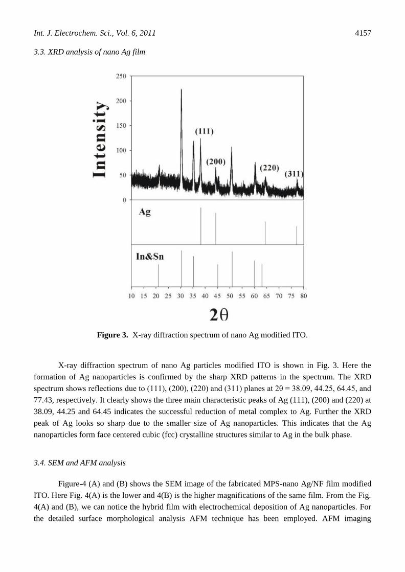
Figure 3. X-ray diffraction spectrum of nano Ag modified ITO.
X-ray diffraction spectrum of nano Ag particles modified ITO is shown in Fig. 3. Here the
formation of Ag nanoparticles is confirmed by the sharp XRD patterns in the spectrum. The XRD
spectrum shows reflections due to (111), (200), (220) and (311) planes at 2θ = 38.09, 44.25, 64.45, and
77.43, respectively. It clearly shows the three main characteristic peaks of Ag (111), (200) and (220) at
38.09, 44.25 and 64.45 indicates the successful reduction of metal complex to Ag. Further the XRD
peak of Ag looks so sharp due to the smaller size of Ag nanoparticles. This indicates that the Ag
nanoparticles form face centered cubic (fcc) crystalline structures similar to Ag in the bulk phase.
3.4. SEM and AFM analysis
Figure-4 (A) and (B) shows the SEM image of the fabricated MPS-nano Ag/NF film modified
ITO. Here Fig. 4(A) is the lower and 4(B) is the higher magnifications of the same film. From the Fig.
4(A) and (B), we can notice the hybrid film with electrochemical deposition of Ag nanoparticles. For
the detailed surface morphological analysis AFM technique has been employed. AFM imaging

Int. J. Electrochem. Sci., Vol. 6, 2011
4158
provides more detailed information involving the surface morphology and homogeneity of the MPS-
nano Ag film modified ITO. Fig. 5 shows typical AFM 3D image of the electrodeposited nano Ag film
on self assembled MPS ITO surface. AFM tapping mode was employed for the surface analysis. It can
be seen that the nano Ag are uniform and compact, which indicated that the metal nano particles are in
well dispersed stage on the self adsorbed MPS layer. Generally, the sample roughness corresponds to
the particle size distribution.
Figure 4. SEM images of the MPS-nano Ag modified ITO (Magnification: (A) x2.0k (15.0 kV) and
(B) x3.5k (15.0 kV)).
Here the average roughness (AR) value was obtained from the several image topographies of
the MPS-nano Ag film. These values are averages calculated from several images acquired in different
regions of the respective sample. In most of the regions the Ag nano particles films exhibit the most
regular, uniform particle dimensions and have low ARs (3.67 nm). Generally bare ITO surface exhibits
a very smooth morphology, with the RMS roughness being smaller than 0.25 nm. However, the

Int. J. Electrochem. Sci., Vol. 6, 2011
4159
increase of the RMS roughness (4.66 nm) of nano Ag film may be due to the increase of density and
size of Ag nano particles on the surface.
Figure 5. AFMs three dimensional view of MPS-nano Ag modified ITO.
The average diameters of the nano Ag particles from these calculations were found in the range
of 20 to 70 nm. Here for the convenience we have examined the modified ITO for the SEM and AFM
analysis. The above discussed results may vary for the GCE surface. Therefore, here we have
compared and discussed the proposed film morphology in the ITO electrode surface.
3.5. Oxygen reduction reaction on MPS-nano Ag/NF film modified GCE
Electrocatalytic activity of the MPS-nano Ag/NF film for oxygen reduction reaction (ORR)
was ascertained by recording cyclic voltammograms for the oxygen saturated pH 7.4 PBS solution.
Here the voltammetric results clearly demonstrate the excellent electrocatalytic activity of MPS-nano
Ag/NF film for ORR in comparison to the unmodified GC electrode. Fig. 6(A) shows the CVs of the
MPS-nano Ag/NF film in oxygen saturated solutions, respectively. A peak at -0.4 V was observed for
the MPS-nano Ag/NF film for ORR during the cathodic scan of potential (Fig. 6(A) (a-h)).
Comparatively, a reduction wave at -0.75 V was noticed for ORR on the unmodified GC electrode
(Fig. 6(A) line (a’)). Thus, an enhanced electrocatalytic activity was noticed for MPS-nano Ag/NF film
over the unmodified GC electrode with a positive shift of the oxygen reduction potential from -0.75 to
-0.4 V and an increase in the current for ORR (Fig. 6(A)). It is to be noted that the film modified GCE
reduced the over potentials for the oxygen reduction reactions. Further the ORR reduction on MPS-
nano Ag/NF film was examined by hydrodynamic voltammetry. Here the rotating glassy carbon disc
electrode (RDE) has been employed for the ORR reaction. As shown in Fig. 6(B), for the increasing
time for oxygen purging the MPS-nano Ag/NF film modified RDE shows increasing reduction current

Int. J. Electrochem. Sci., Vol. 6, 2011
4160
in the potential range of -0.4 to -0.6 V. Previously, various types of electrode modifications were
reported for the ORR studies. Particularly, Pd/MnO2-coated graphite electrode shows ORR at -0.2 V
(in 0.1 M Na2SO4) [49], Cu/MnO2 modified graphite electrode shows ORR at -0.5 V (in 0.1 M
Na2SO4) [50], anthraquinonedisulfonate doped glutaraldehyde cross-linked poly-L-lysine modified
GCE shows oxygen reduction at -0.36 V in 0.1 M PBS (pH 7.0) [51], and Pt-Co/MWCNT modified
glassy carbon disc as an alcohol tolerant for the ORR Catalyst were reported [52]. From the above
discussion it was found that the ORRs were reported in the potential range of -0.2 to -0.5 V. In this
report, for the MPS-nano Ag/Nf film the ORR was found at -0.4 V. This show shat the proposed film
effectively shows the ORR in the suitable potential range comparing with previous literature reports.
Finally the CV and hydrodynamic voltammetric results validates that the proposed MPS-nano Ag/NF
film efficiently applicable for the oxygen reduction reactions, respectively.
Figure 6. (A) CVs of MPS-nano Ag/NF film modified GCE for oxygen reduction reaction in various
time intervals (Oxygen purging time intervals (a-h); 0,30, 60,90 150, 180, 210, 300s). (B) RDE
voltammograms of MPS-nano Ag/NF film on GCE for oxygen purging in various time
intervals (a-g; 0, 60, 120, 180, 240, 300 and 360s); Electrode rotation speed = 400 rpm.

Int. J. Electrochem. Sci., Vol. 6, 2011
4161
3.6. Chronoamperometric studies
Figure 7. Chrono amperometric responses of MPS-nano Ag/NF film modified GCE in pH 7.4 for
oxygen reduction reaction in various time intervals. The curves (a)–(f) correspond to (i) 0, (ii)
60, (iii) 90, (iv) 180 (v) 210 and (v) 330s different time intervals of oxygen purging. Inset
shows the plots of I vs. t−1/2
obtained for the chronoamperometry.
To get an insight into the dynamics of charge transport on the MPS-nano Ag/NF film modified
GCE, we have performed a series of chronoamperometry experiments. Fig. 7 shows the
chronoamperograms obtained for MPS-nano Ag/NF film for the different concentrations of oxygen by
purging in various time intervals. Chronoamperograms obtained at MPS-nano Ag/NF film for oxygen
saturated pH 7.4 PBS with different time intervals of oxygen purging (i) 0, (ii) 60, (iii) 90, (iv) 180 (v)
210 and (v) 330s and inset of the Fig. 7 shows the dependence of net current (I) on t−1/2
derived from
the data of chronoamperometry in the presence of oxygen, respectively. Here the effective (apparent)
diffusion coefficient could be estimated from the slopes of dependencies of net electrolysis current (I)
versus square root of time (t−1/2
) using the Cottrell equation;
I = nFAD1/2
Co /π
1/2t1/2
4. CONCLUSION
In conclusion, this work reports the successful modification of self-adsorbed MPS on pretreated
GCE following with the electrochemical deposition of silver nanoparticles on the glassy carbon
electrode surface. The electrochemical studies proved that the proposed film was stable and active on
the electrode surface. To validate the electrochemical applications of the proposed film modified
electrode, oxygen reduction reactions (ORR) has been examined. The proposed film modified
electrode showed obvious electrocatalytic properties for the ORR by using cyclic voltammetry,

Int. J. Electrochem. Sci., Vol. 6, 2011
4162
hydrodynamic voltammetry and chronoamperometry. In final, this type of film modified electrode
could be applied for the detailed study of ORRs in the industrial applications.
ACKNOWLEDGMENT
This work was supported by grants from National Science Council (NSC) of Taiwan (ROC).
References
1. J.J. Calvente, Z. Kovacova, M.D. Sanchez, R. Andreu, W.R. Fawcett, Langmuir 12 (1996) 5696.
2. I.Turyan, D. Mandler, Isr. J. Chem., 27 (1997) 225.
3. I.Turyan, D. Mandler, J. Am. Chem. Soc., 120 (1998) 10733.
4. D.W.M. Arrigan, T. Iqbal, M. J. Pickup, Electroanal., 13 (2001) 8.
5. M.A. Pasquale, D. P. Barkey, and A. J. Arvia, J. Electrochem. Soc., 152 (2005) C149.
6. J.J. Kim, S.-K. Kim, Y. S. Kim, J. Electroanal. Chem., 542 (2003) 61.
7. S.-E. Bae, A.A. Gewirth, Langmuir 22 (2006) 10315.
8. Z. Hu, T. Ritzdorf, J. Electrochem. Soc., 153 (2006) C467.
9. H.-M. Chen, S.J. Parulekar, A. Zdunek, J. Electrochem. Soc., 155 (2008) D349.
10. N. Terasaki, N. Yamamoto, T. Hiraga, I. Sato, Y. Inoue, S. Yamada, Thin Solid Films 499 (2006)
153.
11. V. Rosca, I.C. Popescu, Electrochem. Commun., 4 (2002) 904.
12. H. Zhao, H. Ju, Anal. Biochem., 350 (2006) 138.
13. A.Narva´ez, G. Sua´rez, I.C. Popescu, I. Katakis, E. Domı´nguez, Biosens. Bioelectron., 15 (2000)
43.
14. S. Bharathi, M. Nogami, S. Ikeda, Langmuir 17 (2001) 1.
15. S.-M. Chen, J. Electroanal Chem., 417 (1996) 145-153.
16. S.-M. Chen, Electrochim Acta 43 (1998) 3359-3369.
17. S. Thiagarajan, S.-M. Chen, Talanata 74 (2007) 212-222.
18. S.-M. Chen, J. Electroanal Chem., 521 (2002) 29-52.
19. Y. Umasankar, S. Thiagarajan, S.-M. chen, Anal Biochem 365 (2007) 122-131.
20. S.-M. Chen, K.-T. Peng, J. Electroanal Chem., 547 (2003) 179-189.
21. D. Tang, R. Yuan, Y. Chai, Y. Liu, J. Dai, X. Zhong, Anal. Bioanal. Chem., 381 (2005) 674.
22. L. Jiang, W. Wang, D. Wu, J. Zhan, Q. Wang, Z. Wu, R. Jin, Mater. Chem. and Phy., 104 (2007)
230.
23. D.R. Shankaran, N. Uehera, T. Kato, Sens. Actuat. B-Chem., 87 (2002) 442.
24. E. Yeager, Electrochim. Acta 29 (1984) 1527.
25. N.M. Markovic, P.N. Ross, in: A. Wieckowski (Ed.), Interfacial Electrochemistry, Marcel Dekker,
New York, 1999, pp. 821–841.
26. N.M. Markovic, P.N. Ross, Surf. Sci. Rep., 45 (2002) 121.
27. M.D. Macia´ , J.M. Campin,˜ E. Herrero, J.M. Feliu, J. Electroanal. Chem., 564 (2004) 141.
28. A.Kuzume, E. Herrero, J.M. Feliu, J. Electroanal. Chem., 599 (2007) 333.
29. M.A. Genshaw, A. Damjanovic, J.O.M. Bockris, J. Electroanal. Chem., 15 (1967) 163.
30. M.A. Rizatti, K. Ju¨ ttner, J. Electroanal. Chem., 144 (1983) 351.
31. S. Sˇ trbac, R.R. Adzˇic,´ J. Serb. Chem. Soc., 57 (1992) 835.
32. S. Sˇ trbac, R.R. Adzˇic,´ Electrochim. Acta 41(1996) 2903.
33. V. Torma, G. Lang, Mag. Kem. Fol., 104 (1998) 265.
34. S.-M. Chen, S.-H. Li, S. Thiagarajan, J. Electrochem. Soc., 154 (2007) E123
35. A.A. Elzatahry, H.M. Hassan, M.E. Youssef, Int. J. Electrochem. Sci., 5 (2010) 1496.
36. S. Thiagarajan, S.-M. Chen, K.-H. Lin, J. Electrochem. Soc., 155 (2008) E33.

Int. J. Electrochem. Sci., Vol. 6, 2011
4163
37. B.-W. Su, S. Thiagarajan, S.-M. Chen, Electroanal., 20 (2008) 1987.
38. P. Norouzi, F. Faridbod, B.Larijani, M.R. Ganjali, Int. J. Electrochem. Sci., 5 (2010) 1213.
39. S. Thiagarajan, S.-M. Chen, J. Solid. State. Electrochem., 13 (2009) 445.
40. R.F. Ngece, N. West, P. M Ndangili, R.A. Olowu, A. Williams, N.Hendricks, S. Mailu, P. Baker,
E. Iwuoh, Int. J. Electrochem. Sci., 6 (2011) 1820.
41. S. Thiagarajan, B.-W. Su, S.-M. Chen, Sens. Actuat. B-Chem. 136 (2009) 464.
42. T.-H. Tsai, S. Thiagarajan, S.-M. Chen, Electroanal., 22 (2010) 680.
43. R.W. Zurilla, R.K. Sen, E.B. Yeager, J. Electrochem. Soc., 125 (1978) 1103.
44. H.S. Wroblow, Y.C. Pan, G. Razumney, J. Electroanal. Chem., 69 (1976) 195.
45. N.R.K. Vilambi, E.J. Taylor, J. Electroanal. Chem., 270 (1989) 61.
46. M.R. Tarasevich, K.A. Radyushkina, V.Y. Filinovskii, R.K. Burshtein, Elektrokhimiya 6 (1970)
1522.
47. A.Damjanovic, M.A. Genshaw, J.M. Bockris, J. Electroanal. Chem., 15 (1967) 173.
48. C. Paliteiro, Electrochim. Acta 39 (1994) 1633.
49. K.-Q. Din, Int. J. Electrochem. Sci., 5 (2010) 668.
50. K.-Q. Ding, Int. J. Electrochem. Sci., 5 (2010) 72.
51. T.-H. Tsai, S.-H. Wang, S.-M. Chen, Int. J. Electrochem. Sci., 6 (2011) 1655.
52. D. M. Acosta, D. L. Fuente, L.G. Arriaga, G.V. Gutiérrez, F.J.R. Varela, Int. J. Electrochem. Sci.,
6 (2011) 1835.
© 2011 by ESG (www.electrochemsci.org)


![Synthesis of magneto-optically active polyanilines · 2017. 4. 26. · sulfonic acid in a polymerization reaction [16]. Optically active camphor sulfonic (CSA) acid is electrostatically](https://img.dokumen.tips/doc/110x75/60b44d78efe5ea264f06dc2a/synthesis-of-magneto-optically-active-polyanilines-2017-4-26-sulfonic-acid.jpg)

![Chemical Methodologies...metanilic acid [21–25], orthanilic acid [26-28], 2,5-diamino benzene sulfonic acid [29] either by chemically or electrochemically. Aniline sulfonic acid](https://img.dokumen.tips/doc/110x75/610e509c25f94f76a746bb02/chemical-metanilic-acid-21a25-orthanilic-acid-26-28-25-diamino-benzene.jpg)


![Td Adsorbed (Tetanus and Diphtheria Toxoids …products.sanofi.ca/en/td-adsorbed.pdfTd ADSORBED [Tetanus and Diphtheria Toxoids Adsorbed], is a sterile, cloudy, white, uniform suspension](https://img.dokumen.tips/doc/110x75/5e5ed39d07f6e0285b51c50f/td-adsorbed-tetanus-and-diphtheria-toxoids-td-adsorbed-tetanus-and-diphtheria.jpg)