Embed Size (px)
Citation preview

AD-A262 904 .R•-9-R-oos
DEMONSTRATION AND FABRICATION OFLARGE AREA 1-3 PZT COMPOSITE PANELS
Quarterly report for:
Contract No. N00014-92-C-0186
Office of Naval Research800 North Quincy Street
Arlington, VA 22217-5000
August 20, 1992 to February 28, 1993
fTXICfrom:(T LU
Fiber Materials, Inc. .5 Morin Street
Biddeford, ME 04005-4497
;j~6 TT E
Apj; r~r'c4 f. public releQso2
93-06663

INTRODUCTION
Fiber Materials, Inc. (FMIe) has been contracted by the
Office of Naval Research (contract #N00014-92-C-0186) to develop
actuator/sensor technology for smart structures through
economical and automated fabrication of large area 1-3
piezocomposite advanced materials.
This one year program, predicated on lead zirconat' titanate
(PZT) rod delivery provided by the sponsor, will fabricate a
2 meter x 2 meter x 5 millimeter test array containing 15 volume
percent PZT rods. Since the start of the program, August 20,
1992, the 2 m x 2 m 1-3 piezocomposite test array has evolved by
direction of the technical sponsor into the following
configuration.
GRP PZT RODEDGESTI
--/2 '~- 79 msy GRP CAPWITH CP P LERCTRO)OESON TOP & BOTTOM
9.6 mm
FLEXIBLE SILVER ADHESNE
1-3 mmVV(-7 M 4ASLN
MATRIX CERAMIC ROSLUekVrW T PZT5H
* 40-50% Microaboo od aIze: 1 mm (.,040) *a*eRod Uspe CaWoRod ing 2-5 mm r .rW )V. 15%
Figure 1
FMI is a registered trademark of Fiber Materials, Inc.
1

The 2 m x 2 m test array will be comprised of 16 tiles
.5 m x .5 m x 5 mm with the configuration represented in
Figure 1. Test samples of the prototype array configuration have
been included by direction of the program technical monitor. The
test samples will involve the following:
S(4) 4" x 4" piezocomposite panels to be delivered
to Bob Ting at NRL Orlando for evaluation.
(2) ]0" x 10" piezocomposite panels to be
I delivered to Wayne Reader at Vector Research for
evaluation.
IThe work presented in the following sections represents
FMI's efforts into the fulfillment of its contract and input into
the evolution of the 1-3 piezocomposite array configuration.
PREFORM TOOLING
Preform tooling was designed to provide for both manual and
automatic insertion of PZT rods for the fabrication of 1-3
piezoco-mposite panels. The tooling design, illustrated in
Figure 2, employs thin copper plates with precise holes as rod
guides so that the PZT rods can be positioned and their locations
maintained during resin impregnation. The copper plates were
patterned by photolithography and chemically etched to provide
very precise hole diameters and locations.
Pcce io'n for -
NIT'fS Crl..
'D•I'('; e"•,' ..... . D .2 ;,
Statement A per telecon Stephen Newfield
ONhR/Code 1225Arlington, VA 22217-5000 (X)
INIWW 4/13/93 ."
2A,
I - • i = , .I

P"Z' COMF-1TE TCQLIMD flATE
0 -............. ....... .
......... O O -TI 10e3 hAF-
KTR:!Z10 THCK OMERTCLER,,VCES. -/- M2 ULRESS VECIFIED
I OUA.tTTfl, INO
Figure 2
Both PZT rods and copper tooling holes were designed to a tight
tolerance so that all rods would fit into the holes with minimum
deviation from the vertical position. As shown in Figure 3, a
photochemically etched copper plate was bonded to an aluminum
base plate, .080" spacers attached, and a second copper plate
bonded to the spacers. This provides preform tooling for the
manual and automatic insertion of PZT rods for fabrication of
10"1 x 20" piezocomposite panels. After resin impregnation and
cure, the tooling plates will be machined away.
III
I I H

IC .......... .. ... SPA SZI
---- --- --- --- ------ ---
I • I
II
I Figure 3
The fabrication of this preform tooling was completed during
the first quarter of this program. The copper tooling plates,
base plates and spacers were designed, built and have been ready
for assembly since mid December 1992. Subscale parts were
fabricated with non-compliant PZT rods to evaluate rod insertion
and resin impregnation techniques.
PZT RODS
Early in the first quarter, Ceramics Process Systems (CPS),
who was contracted by the sponsor to supply the PZT rods to FMI,
reviewed their PZT rod manufacturing capabilities with FMI and a
specification (Figure 4) was agreed upon for the 600,000 PZT-5H
rods.
IIIII
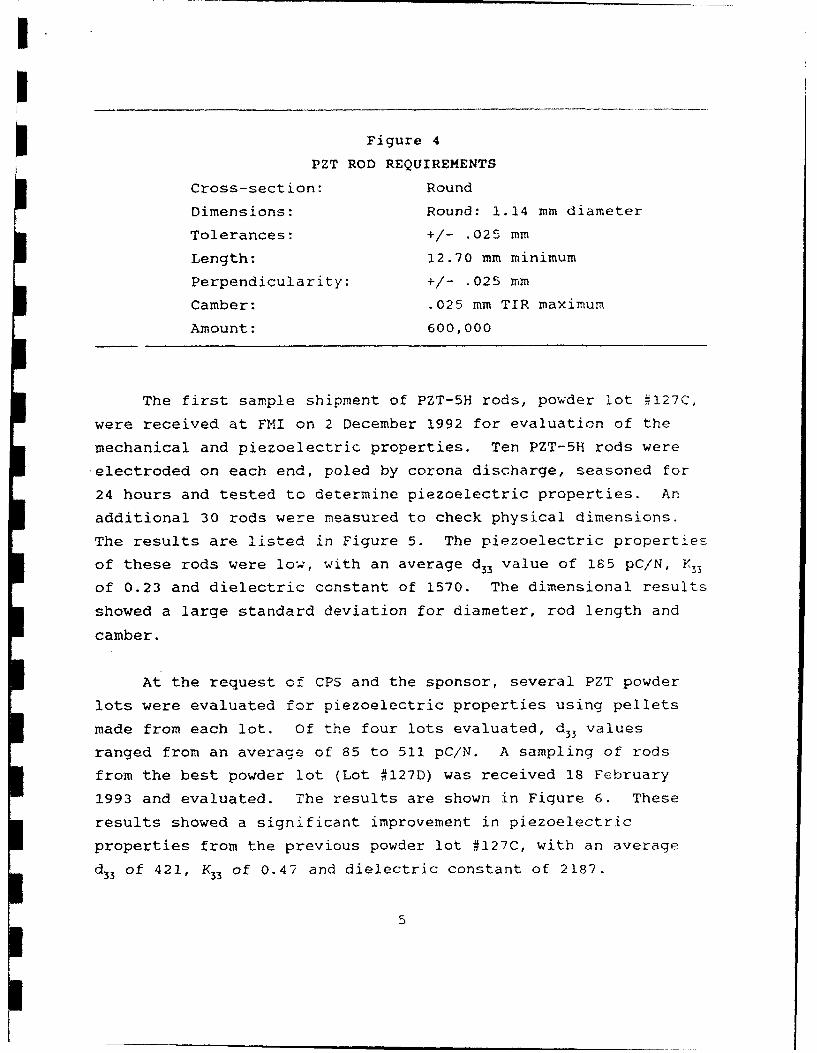
Figure 4
PZT ROD REQUIREMENTS
Cross-section: Round
Dimensions: Round: 1.14 mm diameter
Tolerances: +/- .025 mm
Length: 12.70 mm minimum
Perpendicularity: +/- .025 mm
Camber: .025 mm TIR maximum
Amount: 600,000
The first sample shipment of PZT-5H rods, powder lot •127C,
were received at FMI on 2 December 1992 for evaluation of the
mechanical and piezoelectric properties. Ten PZT-5H rods wereelectroded on each end, poled by corona discharge, seasoned for
24 hours and tested to determine piezoelectric properties. An
additional 30 rods were neasured to check physical dimensions.
The results are listed in Figure 5. The piezoelectric properties
of these rods were low, with an average d 33 value of 185 pC/N, K33
of 0.23 and dielectric constant of 1570. The dimensional results
showed a large standard deviation for diameter, rod length and
camber.
At the request of CPS and the sponsor, several PZT powder
lots were evaluated for piezoelectric properties using pellets
made from each lot. Of the four lots evaluated, d33 values
ranged from an average of 85 to 511 pC/N. A sampling of rods
from the best powder lot (Lot #127D) was received 18 February
1993 and evaluated. The results are shown in Figure 6. These
results showed a significant improvement in piezoelectric
properties from the previous powder lot #127C, with an average
d33 of 421, K33 of 0.47 and dielectric constant of 2187.
5

I.
Figure 5
CPS PZT-5H RODS
TESTED 04 DECEMBER 1992
PIEZOELECTRIC PROPERTIES:
DENSITY DIELECTRIC K33 Nt d33(g/cc) CONSTANT (m-Hz) (pC/N)
7.0 1570 0.23 1592 185
DIMENSIONAL PROPERTIES:
LENGTH DISTRIBUTION CAMBER DISTRIBUTION
N OF RODS 0 OF ROOS
10110
2 20 0
.510 .sO .520 .630 8640 .560 .680 .560 0 1 2 3 4 6LENGT H (.il s) CAMBE£R (.asl)
DIAMETER UfSTRIBUTION OUT-OF-ROUND DISTRIBUTION
5 OF RODS POF RO_3
2021 :11 - ___
43 44 . a'- -
43 44 46 4 4 48 .9 0 2
DIAMETEA (mits) DIAM.ITEIR DELTA (mvI)
6

I !
Figure 6
CPS PZT-5H RODS
TESTED 18 FEBRUARY 1993
PIEZOELECTRIC PROPERTIES:
DENSITY DIELECTRIC K33 Nt D33(g/cc) CONSTANT (m-Hz) (pC/N)
7.2 2187 0.47 1554 421
DIMENSIONAL PROPERTIES.
LENGTH DQ-TRtBLUTION CAMBER DISTRIBUTION
0 OF RODS v OF RODS
14
014
12" ~8
a.a
4 I,
o -'.480 .480 .4g0 .600 510 520 .630 -.630 1 2 3 4 6
LEN.,- t .ilsl CAMBER (.:|b)
DIAMETER C4 STRISUTiON OUT-OF-ROUND DISTRIBUTION
0 OF RODS OF RODS
-' 1012.6
100
220
SH
43 44 45 .7 8 49 0 z
DIAME'7• (mits) DIAMETER1 DELTA (,.,I•,I
7

3 Rod physical di~enslons improved as shown by the tighter diameter
distribution and rez-uced camber measurements. Although the
dimensional quality of this last batch of rods is acceptable fot
manual rod insertio-, further improvement will be needed for
automated rod inserzion. The delay in providing PZT rods has put
FMI behind schedule in preform fabrication (see Figure 7).
W"O' PROGRAM STATUSF'92 FY93
0~ N D J F~ M A MJMANUAL INSERTION PREFORM:
- DESIGN TOOLING- FAB TOOLINGS- SUBSCALE TEST
AUTO INSERTION PREFORWEVALUATE DESIGNS ,..
RESIN IMPREGNATIONý I I* -SUBSCALE TESTS 1"
D- DESIGN MOLDl-FABRICATE MOLD i
CONTINUOUS POLING:- DESIGN EQUIPMENT +FABRICAT EOUIPNaENT
ASSEMBLE AND QJALIFY
PANEL ASSEMBLY:FABRICATE PANELS
- ASSEMBLE AND CABLE- ENCAPSULATE
Figure 7
AUTOMATIC ROD ITSERION
I Of all the steps involved in piezocomposite fabrication, rod
insertion is the most time consuming. While the Ultraloom6
3 allows precise positioning of each PZT rod, this automated cycle
requires up to 15 seconds per insertion. Since fabrication of
3 the 2 m x 2 m panel will utilize almost 600,000 rods, work has
UltraloomO is a registered trademark of Fiber Materials, Inc.
8II]

been conducted to modify the Ultraloom insertion system to
accommodate multiple rods in each cycle. The modification
significantly improves the efficiency of the insertion system.
The foundation for the modifications lies in the concept of
a multiple rod dispenser that can be attached to the existing
insertion arm. several different approaches are currently under
evaluation, but all will lead to the basic scenario of a series
of rods loaded onto a grooved holder, aligned to the holes in the
copper screen tooling and lowered into place.
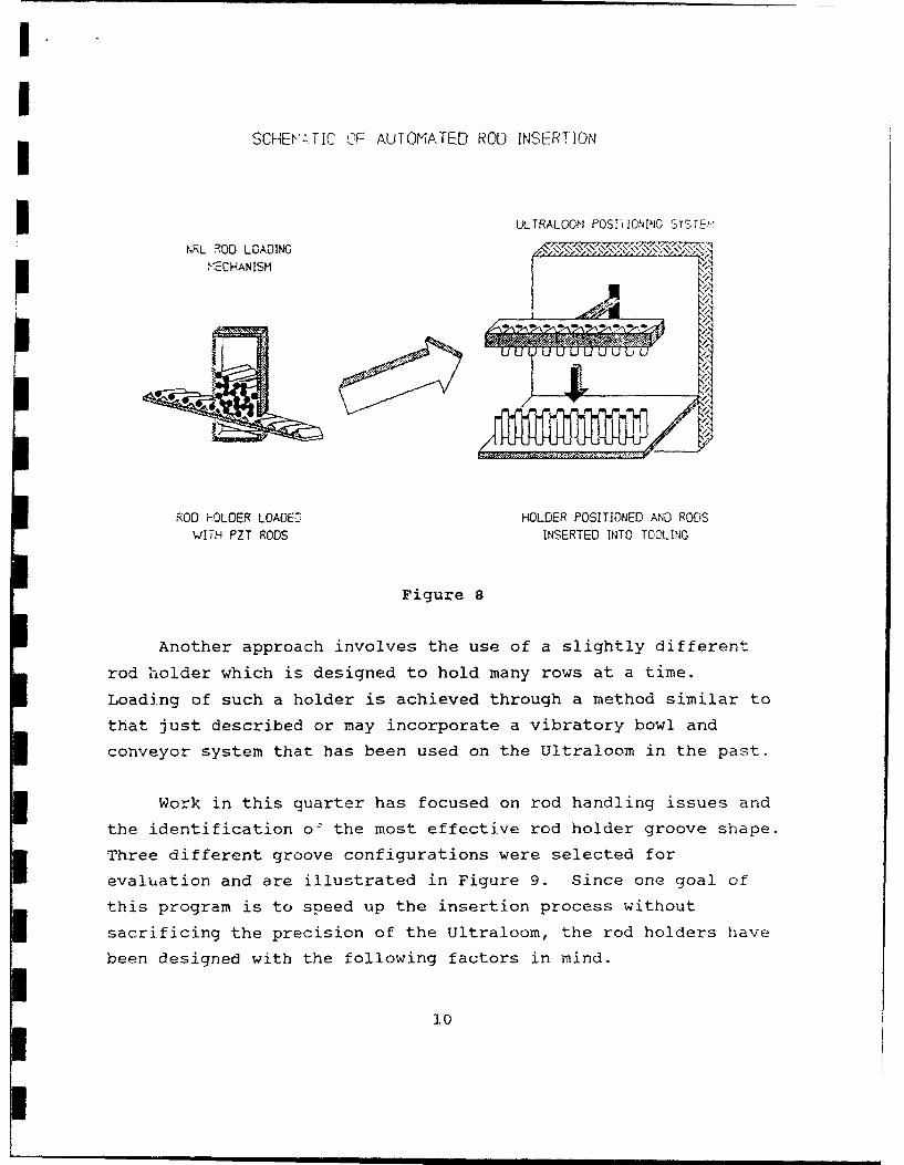
one insertion approach builds on a rod dispenser loading
mechanism developed by Dr. Kahn et al under a related program
being conducted at NRL. A schematic of this system is presented
in Figure 8. This set-up consists of a single row of rods loaded
onto a holder with each pass through the rod bin. The holder is
then fed to the Ultraloom positi~oning head which lines up the
rods with the tooling and inserts the rods into the appropriate
holes. Since the rods supplied by CPS are round in cross-
I section, rod handling issues are simplified and offer potential
for high-speed automation not achievable with the more difficult
I to handle square cross-section PZT rods that FMI has used in the
past.
I.I
SCHEV-. IC O.F AUTOMATED ROD INSERTION
ULTRALOOM POS[1IONING SYSTE!
NRL ROD LOAD)ING e.il1,e_ 1
ý'=CHANISM
ROD f-OLOER LOADE27 HOLDER POSITIONED AND RODSWITH PZT RODS INSERTED INTO TOOLING
Figure 8
Another approach involves the use of a slightly different
rod holder which is designed to hold many rows at a time.
Loading of such a holder is achieved through a method similar to
that just described or may incorporate a vibratory bowl and
conveyor system that has been used on the Ultraloom in the past.
Work in this quarter has focused on rod handling issues and
the identification oý the most effective rod holder groove shape.
Three different groove configurations were selected for
evaluation and are illustrated in Figure 9. Since one goal of
this program is to speed up the insertion process without
sacrificing the precision of the Ultraloom, the rod holders have
been designed with the following factors in mind.
10

I- ability to hold tods in position
ease of filling each groove with rods
-I machinability and cost
- feasibility for scale-up to .5 m x .5 rn dem ons.s r at on
tiles
durability
I INSERTER GROOVE SHAPES
I Figure 9
I The dimensions of these rod holders have been specified to
position the rods at 2.6 mm spacing, center-to-center. This is
dictated by the rod volume loading of the composite. Each of the
different groove shapes was sized to allow precise location of3 each rod with minimal movement within the groove. Once the rods
are loaded into the trays and the holder capped for insertion, no
shifting of the rods can occur. Only with such tight tolerances
can the precision of the original Ultraloom mechanism be
reproduced in a high speed, high volume insertion operation.
Twelve steel single row rod holders were fabricated, four of
Seach shape. Relative effectiveness of each was evaluated and
compared in the course of rodding a 101 mm x 101 mm x 6.1 mm
part. Rods were loaded onto a tray, then positioned on the
II|

tooling and inserted using a manual operation that i;imiulates thOn
automated procedure. By positioning and loading 35 rods at a
time, these trays in themselves offer a 30-fold improvement over
single rod insertion rates. Initial experiments were hampered by
variations in the diameters and straightness of the PZT rods, but
CPS has made significant improvements in these areas. As better
quality rods become available next quarter, a more detailed
sequence of mecnanical handling and dispensing operations will be
identified and optimized. This in turn will facilitate
translating the manual operation into an automated process
through modL2ications and additions to the Ultraloom equipment.
10" X 20" RTM MOLD
A Resin Transfer Molding (TN) tool was designed to
fabricate piezocomposite panels up to 10" x 20" x .75". The tool
is shown irt Figure 10. The desi(,n concept is based on the RTM
tool developed for the 4" x 4" piezocomposites. The PZT rcds are
fixed in a base and located in the tool cavity. The top plate is
bolted to the bottom plate with O-rings providing for an air
tight seal. Air is evacuated from the tool with a vacuum pump
and then the resin injected into the tool under pressure After
the mold cavity is completely filled with rc'in and all voids
eliminated, the vacuum pump and resin lines are disconnected.
The piezocomposite is cured at room or moderate temperature to
complete the molding operation.
12

RESIN TRANSFER HOLD
VENT
VENT OU IL E T
RES IN /'-L ----- INLET VN
MOLDESN
PRESSURERESERVOIR
COMPOSITE10" X 20"
Figure 10
Several design changes were introduced in the RTM mold. The
top p3ate is clear acrylic so that resin flow and void
elimination can be studied during the resin injection operation.
The acrylic plate was designed so that the center deflection will
be minimal at full vacuum. The holes in the top plate are
located at the center and four corners. This arrangement will
permit flexibility in attaching resin inlet and vacuum lines to
the tool. One system would be to inject the resin at the center
and evacuate the air from the four corners. If smaller
piezocomposites are desired, part of the tool cavity can be
filled with an aluminum plate. The multiple holes in the top
plate will still allow for resin inlet and vacuum lines. Ports
that are not needed can be sealed with plugs. Another tool
feature is that the cavity is formed by four rails, two side and
two end rails. The rail thickness is equal to the cavity depth.
This design allows changing the cavity depth by changing just the
13

rails and not the entire tool. Another advantage is that
piezocomposite demolding is simplified through tool dismantling.
A resin transfer study has been conducted to debug the
system using a simple resin system. Best results were achieved
when a partial vacuum was coupled with oack pressure on the
resin. The pressure vessel was equipped with an acrylic top.
This allowed the resin mixture to be degassed within the vessel
rather than in a desiccator and eliminated a second degassing
step, the transfer of the resin from the desiccator to the
pressure vessel.
MATRIX RESIN DEVELOPMENT
During the previous quarter, effort was devoted to exploring
those variables that contribute to near net shape molding of
piezocomposites using a resin transfer process. The matrix
resins used in this work consisted of HD68 (soft), HD77 (medium)
and HD85J (hard) epoxy formulations. Successful small scale
(e.g. 4" x 4") moldings were made from non-reinforced as well as
reinforced piezocomposites having Z direction rods.
Matrix resin development has continued during this quarter
with the emphasis shifting away from epoxy systems toward
urethane systems containing Expancel thermoplastic microballoons.
This redirection of the matrix resin effort was made by the
program technical monitor during the December quarterly review
meeting.
Initial urethane studies were conducted using the
recommended Conathane EN-2 system. This resin has an advantage
in that it has low viscosity of only 1200 cps at room
temperature, from time of initial mixing. Formulations were
prepared using 50 volume percent Expancel 551DE microballoons.
The microballoons were dispersed in the "B" side of the
14
formulation in an effort to extend the pot lite al the :ri
system. The "A" side was then added and mixed in until
homogenous system was reached. The matrix was degassed for Taouut
1 hour @ 30 mHg bu, still contained entrapped air and at thit;
point was too viscous to handle.
Trials were conducted with EN-2 using Expancel 551DU
unexpanded microballoons as the filler. Mixes were prepared that
degassed quite readily and had low initial viscosity when an
amount of microballoons, on an equal weight basis to 55iDE, was
incorporated. Curing of these mixes was done at 1000C which is
j the recommended expansion temperature for 551DU. Using this high
a cure temperature apparently caused the urethane to cure before
the full expansion of 551DU microballoons.
Attempts were made to modify the "A" side of EN-2 with
phenol to form a blocked isocyanate which would provide an
increased pot life. While some success in extending the pot life
to about 2 hours was noted, it was also apparent that the quality
of the cured resin was not the same as the unmodified EN-2. This
approach has since been abandoned.
Samples were solicited from several vendors in an effort to
obtain urethane systems with long pot lives and low viscosities.
The following products were received for evaluation:I- Desmodur N3200 and Desmophen 1150 (Bayer, Inc.)
- Polathane STE-73D, Polamine 650 and Polamine 1000 (Air
Products)
Mix ratios were calculated at an isocyanate index of 1.05
with small batches of unfilled resin prepared and cured at 60'C
for 16 hours. Shore D hardness was measured for each formulation
and the values obtained were similar to those obtained with
Conathane EN-2. Viscosity and pot life were measured on two
15II

I
I systems that theoretically would have the longest pot life. iL
data is shown Table 1. Of the two systems, the one based on
JDesmophen 1150/Desmodur N-3200 offered the most potential for the
RTM process.
I Table 1
SCREENING OF LOW VISCOSITY AND LOG POT LIFE URETHANE SYSTEMS
I Formutation, PeW
Material 1 2 3 S 4 5 6- -Polathane STE-730 58.3 52.6 45.1 ..
Oesmodur N3200 -- 35.9 -- - 30.8 24.8
Polamine 650 .. 47.4 -. 69.2 --
Polamine 1000 .. .. .. 54.9 -- 75.2
Desmophen 1150 41.7 64.1 -- --
Gardner viscosity ....... i& RT Z, + Y.. . .. i
, 60 C U-V P .. .. .. ..
Estimated pot life .... ...
@ 60'C, hr 1-2 4-5 .. .. .
Cure 16 hrs @ 60 C
Shore 0 hardness @ 210C 18 28 30 22 33 26,
RTM PROCESS STUDIES
Formulations of the Desmodur N3200/Desmonphen 1150 were
prepared incorporating both 40 and 50 volume percent of Expancel
551DE microballoons. Mix ratios, density, hardness of cured
specimens and temperature viscosity of neat and filled
formulations are shown in Table 2.
I
I 16

II table 2
UREIHANE MATRIX RESIN FORMULAIIGNS (P6W)
I 1 50 Vottr % 40 VotuwAzmaterials Neat microbaLtoons aicrcbtIoors
Desmophen 1150 64.08 61.93 6Z.63 .
Desnmodur N-3200 35.92 34.71 35.10
Expancet 551"E -- 3.36 2.27
Syk A-50l 0.3 0.3 C.3
Cure __ hrs 60'CI Propo•-ties . .............. .. .
Dens'.ty @ RT, g/cc 1.077 0.584 0.68
Shorc D hardness 2 21 °C 28 22 23
Viscosity 2 23°C, cps 3400 60800 19500
Small scale (4" x 4") RTM moldings were prepared in an
effort to study the flow and rate of fill properties of the 40
and 50 microballoon volume percent formulations. Mixes
containing 50 volume percent microballoons were heated to 600C
prior to transfer and filled the void space of the mold quite
readily. The resulting molded parts were sectioned and examined
for voids. Very few voids were detected. Likewise, 40 percent
filled mixes were molded at both room temperature and 60°C with
similar good result. RTM processing of piezocomposites having
closely spaced PZT rods were also prepared without undue
difficulty.
In an effort to estimate the pot life of the filled
formulations, a viscosity study was carried out. The viscosity
data obtained are shown graphically in Figure 11. From the data,
it is evident that at least a 3 hour pot life is available at
600C for both 40 and 50 percent volume filled formulations. At
room temperature the 40 percent filled material should have a pot
life in excess of 7 hours. This data makes the Desmodur
N3200/Desmophen 1150 formulation amenable to the RTM process.
Wayne Reader from Vector Research is evaluating a neat resin
17
"Im l

I
I sample of the formulation for room temperature modulus. FI .
waiting for the results before we proceed onward.IDESMOPHEN 1150 / DESMODUR N3200 URETHANEFILLED WITH MICROBALLOONS
POT LIFE BY VISCOSITY
I VISCOSITY (cpa$
-.- AO 4 RT -e- 40%' * 50C - 0% 6 V•O.C
100000 . /"
0, PROCE33ING MAX. o
10000 -
0 1 2 3 A 5 a 7
AGE OF RESIN MIX (hra)
Figure 11
COMPRESSION TESTING OF FILLED URETHANE FORMULATIONS
Compression tests were performed in accordance with ASTM
test method D575-91. Both 40 and 50 volume percent specimens
were prepared, cured for 16 hours at 60 0 C and tested. The data
obtained is graphically presented in Figure 12. The data shows
that 40% loading by volume produces a stiffer material than a 50%
volume loading of the Expancel microballoons.
18

I.
DESMOPHEN 1150 / DESMODUR N3200 URETHANEFILLED WITH MICROBALLOONS
COMPRESSION TEST AT ROOM TEMPERATURE
STRESS (PSI)250 -
-G- 40% MICRO.ALLOON8 -6- % MICROGALLOONF8
200 --...
150 ................. . ... ................. .. ....... .......... .. ..... . ..
15010 .. ....
0 5 to 15 20 25 30% DEFLECTION
Figure 12
WATERPROOF COATING OF PIEZOCOMPOSITES
Initial work on waterproof coatings for 3.5 inch disc shaped
piezocomposites involved dip coating with Conathane EN-2 and
curing at room temperature for 16 hours plus 3 hours at 60 0C.
The composites were then tested on an HP 4274A multifrequency LCR
meter for capacitance, dissipation factor, resistance and
impedance. These tests were run at room temperature both dry and
after immersion in seawater. The testing in seawater revealed
that even with multiple dip coats of EN-2 the capacitance
increased significantly, while both resistance and impedance
decreased. Assuming that EN-2 had poor moisture transmission
properties alternate coating materials were tried.
Among the materials tested was Saran which is known to have
excellent barrier properties. The Saran was applied to the
composite by wrapping and then heat shrinking into place prior to
overcoating with EN-2. This approach did not solve the problem.
A lacquer containing a vinylidene chloride-acrylonitrile
19

I.copolymer was developed and used to bond multiple layer ot lsar•n
to the composite. These specimens were then overcoated with E•-2
as the final sealant coat. This improved the electrical
properties of composites immersed in seawater but they were still
not considered acceptable. It was then assumed that the coatingqs
were preventing penetration of seawater and it must be the
influence of the seawater as a conductor that caused changes in
capacitance and resistance.
I Seawater acts as a partial conductor and simulates a common
conductive plate being brought into contact with the waterproof
coating of the composite. The coating then acts as a dielectric
between two plates (e.g. electrode of the composite and the
seawater) and thus creates a capacitance. Since the seawater is
common to all surfaces of the immersed composite it acts to"connect" the "capacitors" that are formed across the coating,
thereby adding two series capacitors across the electrodes of the
composite.
For example, a composite coated with EN-2 at a thickness of
0.008 inch has a measured capacitance of 316.2 pF in air and
934.2 pF when immersed in seawater. The electrode area of the
composite is 9.62 m2 and the dielectric constant of EN-2 is given
as 4.69 @ IKHz. The capacitance across the EN-2 coating is,
C= 0.225KA! S
where: c = capacitance in pF
* K = dielectric constant
A = area of one panel (in 2 )
I S = spacing between panels (in)
I
I

I.
and: C- 0. 225x4, 96x9.62 268iI0.008
This capacitance represents the value of one of two
capacitors in series, added across the disc. Two series
capacitors, each with a capacitance of 1268 pF combine to form a
capacitance of 634 pF as shown by the following equation:
iC 'C
If this value is added to 316.2 pF, the measured capacitance
I in air, the total capacitance is 950.2 pF. The actual measured
capacitance in seawater was 934.2 pF. To reduce this capacitance
effect a thicker coating or a thin coating with a lower
dielectric constant would have to be used.
Thickness of EN-2 waterproof coatings on deliverable
3.5 inch diameter piezocomposites was increased to an average of
0.080 inches. The method of coating application was changed from
multilayer dip and brush coating to casting a single layer in
place in one operation. Typical test results obtained on the
piezocomposites coated at this thickness are as follows:
PN 16927 LCR TestinQ @ IKHz
Test Dissipation
Condition Capacitance Factor Resistance Impedance
Dry 1.687 nF 0.032 cOK 94.3 Kf
After 20 hrsin seawater 1.730 nF 0.034 cOKn 97.6 KQ
21
Iii i i i I I I
All of the disc shaped piezocomposite deliverables were
treated in this manner and shipped to Robert Gallant of Vector
Research Center.
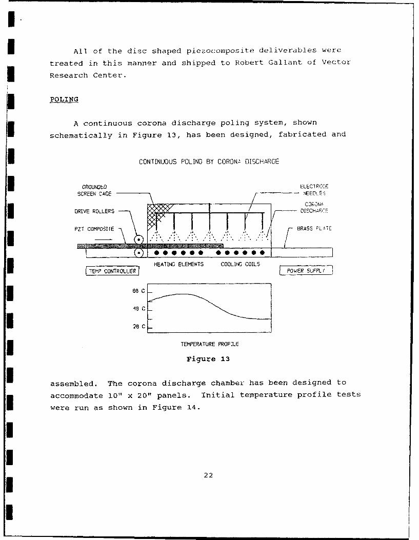
POLING
A continuous corona discharge poling system, shown
schematically in Figure 13, has been designed, fabricated and
CONTINUOUS POLING BY CORONa DISCHARGE
GROUNDED ELECTRCOESCREEN CAGE iNEEOL Eý-
S..... [i- 41DRIVE ROLLERS OISCH'F-' ýz
PZT COMPOSITE BRASS PL.AT1
HEATING ELEMENTS COOLIMC COILS
64C•
21 C
TEMPERATURE PROFILE
Figure 13
assembled. The corona discharge chamber has been designed to
accommodate 10" x 20" panels. Initial temperature profile tests
were run as shown in Figure 14.
22

ICORONA POLING CHAMBERBASE PLATE TEMP PROFILE
TEMPERATURE (deg C)70-
3 0 ....... .... .... ..... -.. .... . .......... . ........ . .... . ................ . . . . . . . . . . . . . . . . . . . . . . . . . . . . .
0 20-1 0il .. I .... ..... ....... - ...... . ..... .... ....... ..-
0 2 4 6 8 10 12 14 16 18 20 22 24DISTANCE FROM ENTRANCE (in)
60C. HIGH H20 FLOW 6 60C. LOW H20 FLOW
65C, LOW H20 FLOW V= 65C, 2 H20 CHANNELS
Figure 14
I A roller drive system has been designed, built and installed at
the entrance end of the poling chamber to precisely control the
feed rate of the piezocomposite panels as they are transported
through the chamber. This design is based on characterization
tests run on a batch type corona discharge system currently used
at FMI. Electrode configuration, temperature, voltage and time
were some of the parameters optimized and incorporated into this
new design. The system design allows a piezocomposite panel to
be fed through the poling chamber at an optimized speed rate,
heated to 60°C and subjected to a 25 KV electric field. This
process poles the PZT rods within the panel. The panel will then
pass through a cooled zone to reduce the temperature while
maintaining the electric field thus assuring that depoling will
not occur during cool down. The d 33 of the rods within the panel
will be measured with a Berlincourt meter to ensure sufficient
poling has occurred. Tests will be run during the next few weeks
to optimize the poling parameters and to qualify the system for
poling panels.
23
I.