Embed Size (px)
Citation preview

FabricationManual
3A CompositesAugust 2013 1
The Foamed PVC Family

3A CompositesAugust 2013 2
Foreword Thank you for choosing a 3A Composites product for your graphic display applications.
We have compiled this Fabrication Manual based on our Fabrication Guide, which is divided into the following sections:
MountingRepositioning VinylDirect Digital PrintingDirect Screen PrintingPaintingKnife CuttingSaw CuttingRoutingDie Cutting / PunchingEmbossingForming CurvesAppendix I: MSDS (Material Data Safety Sheet)Appendix II: Specifications
This Fabrication Guide was created to incorporate the most common fabrication methods that are used with 3A Composites’ line of graphics display products. Not all fabrication methods are compatible with each product, but this format was kept forconsistency purposes. The term “the substrate” is used throughout this guide and is meant to apply to all members of the substrate family unless noted otherwise. Those fabrication methods that do not apply to a certain product are stated with a short explanation and a recommendation for an alternative product that fits that application method.
This manual also contains Appendix I which provides a Material Safety Data Sheet section. Appendix II includes an adhesives, fastening and storage guidelines section. Any unique product information will be contained in Appendix II. See Table ofContents. An Appendix III section lists products that can be used in conjunction with 3A Composites products. 3A Composites is not responsible for the performance of any of these products when used independently or with any 3A Composites product.
The date of the last revision is shown on the bottom right hand corner of each page. Please make sure you have the most current version by going to GraphicDisplay.com and selecting the document library.
If you have any further questions about our product or about how to use this manual, please feel free to contact us at1-800-626-3365.
PLEASE NOTE:TRIALING IS RECOMMENDED TO ENSURE SUITABILITY FOR THE PROPOSED APPLICATION AND
FABRICATION BEFORE FULL-SCALE COMMERCIALIZATION.

3A CompositesAugust 2013 3
Table of ContentsTable of Contents . . . . . . . . . . . . . . . . . . . . . . . . . . . . . . . . . . . . . . . . . . . . . . . . . . . . . 3
Introduction3A Composites Family of Products . . . . . . . . . . . . . . . . . . . . . . . . . . . . . . . . . . . . . . . . . . . . .7Choosing Your Graphic Display Board . . . . . . . . . . . . . . . . . . . . . . . . . . . . . . . . . . . . . . . .11Introduction to Sintra. . . . . . . . . . . . . . . . . . . . . . . . . . . . . . . . . . . . . . . . . . . . . . . . . . . . . . 12 Why Choose Sintra? . . . . . . . . . . . . . . . . . . . . . . . . . . . . . . . . . . . . . . . . . . . . . . . . . . . . . . .12Sintra Product Availability. . . . . . . . . . . . . . . . . . . . . . . . . . . . . . . . . . . . . . . . . . . . . . . . . . .12Sintra Application & Fabrication Guides . . . . . . . . . . . . . . . . . . . . . . . . . . . . . . . . . . . . . . 13 Section I: MountingMounting –– General Notes. . . . . . . . . . . . . . . . . . . . . . . . . . . . . . . . . . . . . . . . . . . . . . . .14A Note on Archival Mounting (Conservation Framing) . . . . . . . . . . . . . . . . . . . . . . . . . . .14Methods for Mounting . . . . . . . . . . . . . . . . . . . . . . . . . . . . . . . . . . . . . . . . . . . . . . . . . . . .14Surface Preparation . . . . . . . . . . . . . . . . . . . . . . . . . . . . . . . . . . . . . . . . . . . . . . . . . . . . . . .14Other Considerations . . . . . . . . . . . . . . . . . . . . . . . . . . . . . . . . . . . . . . . . . . . . . . . . . . . . .15Hot Mounting — General Notes . . . . . . . . . . . . . . . . . . . . . . . . . . . . . . . . . . . . . . . . . . . . 15Cold Mounting — General Notes . . . . . . . . . . . . . . . . . . . . . . . . . . . . . . . . . . . . . . . . . . . .15 Getting Good Adhesion . . . . . . . . . . . . . . . . . . . . . . . . . . . . . . . . . . . . . . . . . . . . . . . . . 15 Demounting Bad Mounts . . . . . . . . . . . . . . . . . . . . . . . . . . . . . . . . . . . . . . . . . . . . . . . .16 Avoiding Wrinkles and Surface Blemishes . . . . . . . . . . . . . . . . . . . . . . . . . . . . . . . . . . 16 Clear Overlays . . . . . . . . . . . . . . . . . . . . . . . . . . . . . . . . . . . . . . . . . . . . . . . . . . . . . . . . .16Cold Mounting Procedures . . . . . . . . . . . . . . . . . . . . . . . . . . . . . . . . . . . . . . . . . . . . . . . . 16 Cold Mounting by Hand Using Transfer Adhesive . . . . . . . . . . . . . . . . . . . . . . . . . . . . . .16 Cold Mounting by Hand or Press Using Spray Adhesive . . . . . . . . . . . . . . . . . . . . . . . . . . 17 Cold Mounting by Roller Laminator with an Adhesive-backed Graphic . . . . . . . . . . . . . . 17 A Note on Cold Mounting Non-Porous Graphics . . . . . . . . . . . . . . . . . . . . . . . . . . . . . . .17 A Note on Cold Mounting Porous Graphics . . . . . . . . . . . . . . . . . . . . . . . . . . . . . . . . . . 18 A Note on Cold Mounting with Pressure Sensitive Tapes . . . . . . . . . . . . . . . . . . . . . .18 A Note on Mounting Sintra Material to Sintra Material. . . . . . . . . . . . . . . . . . . . . . . . .18 Troubleshooting Chart Using Cold Mounting Presses . . . . . . . . . . . . . . . . . . . . . . . . . . .19
Section II: Repositioning VinylVinyl — General Notes . . . . . . . . . . . . . . . . . . . . . . . . . . . . . . . . . . . . . . . . . . . . . . . . . . . . 20Surface Preparation . . . . . . . . . . . . . . . . . . . . . . . . . . . . . . . . . . . . . . . . . . . . . . . . . . . . . . .20Repositioning the Vinyl . . . . . . . . . . . . . . . . . . . . . . . . . . . . . . . . . . . . . . . . . . . . . . . . . . . . 20
Section III: Direct Digital PrintingDirect Digital Printing — General Notes . . . . . . . . . . . . . . . . . . . . . . . . . . . . . . . . . . . . . .21Surface Preparation . . . . . . . . . . . . . . . . . . . . . . . . . . . . . . . . . . . . . . . . . . . . . . . . . . . . . . .21Suitable Inks . . . . . . . . . . . . . . . . . . . . . . . . . . . . . . . . . . . . . . . . . . . . . . . . . . . . . . . . . . . .21

3A CompositesAugust 2013 4
Table of Contents Section IV: Direct Screen PrintingDirect Screen Printing — General Notes . . . . . . . . . . . . . . . . . . . . . . . . . . . . . . . . . . . . . . .21Surface Preparation . . . . . . . . . . . . . . . . . . . . . . . . . . . . . . . . . . . . . . . . . . . . . . . . . . . . . . . 21Suitable Inks . . . . . . . . . . . . . . . . . . . . . . . . . . . . . . . . . . . . . . . . . . . . . . . . . . . . . . . . . . . . 22 Ink Curing . . . . . . . . . . . . . . . . . . . . . . . . . . . . . . . . . . . . . . . . . . . . . . . . . . . . . . . . . . . . . . . 22
Section V: PaintingPainting — General Notes . . . . . . . . . . . . . . . . . . . . . . . . . . . . . . . . . . . . . . . . . . . . . . . . .22Surface Preparation . . . . . . . . . . . . . . . . . . . . . . . . . . . . . . . . . . . . . . . . . . . . . . . . . . . . . . 22 Suitable Paints . . . . . . . . . . . . . . . . . . . . . . . . . . . . . . . . . . . . . . . . . . . . . . . . . . . . . . . . . 23Adhesion Test . . . . . . . . . . . . . . . . . . . . . . . . . . . . . . . . . . . . . . . . . . . . . . . . . . . . . . . . . . .23Application . . . . . . . . . . . . . . . . . . . . . . . . . . . . . . . . . . . . . . . . . . . . . . . . . . . . . . . . . . . . .23Drying . . . . . . . . . . . . . . . . . . . . . . . . . . . . . . . . . . . . . . . . . . . . . . . . . . . . . . . . . . . . . . . . . 23Edge Treatment . . . . . . . . . . . . . . . . . . . . . . . . . . . . . . . . . . . . . . . . . . . . . . . . . . . . . . . . . .24Table I — Advantages/Disadvantages of Types of Paints . . . . . . . . . . . . . . . . . . . . . . . . .25Table II — Advantages/Disadvantages of Types of Primers . . . . . . . . . . . . . . . . . . . . . . . 26Table III — Advantages/Disadvantages of Types of U.V. Protection . . . . . . . . . . . . . . . . . 26
Section VI: CuttingCutting — General Notes . . . . . . . . . . . . . . . . . . . . . . . . . . . . . . . . . . . . . . . . . . . . . . . . . 27
Knife Cutting Knife Cutting . . . . . . . . . . . . . . . . . . . . . . . . . . . . . . . . . . . . . . . . . . . . . . . . . . . . .27
Shearing Shearing . . . . . . . . . . . . . . . . . . . . . . . . . . . . . . . . . . . . . . . . . . . . . . . . . . . . . . . . 27
Saw Cutting Saw Cutting. . . . . . . . . . . . . . . . . . . . . . . . . . . . . . . . . . . . . . . . . . . . . . . . . . . . . .27 Problemshooting with Sawing . . . . . . . . . . . . . . . . . . . . . . . . . . . . . . . . . . . . . . 27 Milling . . . . . . . . . . . . . . . . . . . . . . . . . . . . . . . . . . . . . . . . . . . . . . . . . . . . . . . . .28 Edge Finishing . . . . . . . . . . . . . . . . . . . . . . . . . . . . . . . . . . . . . . . . . . . . . . . . . . 28 Surface Finishing . . . . . . . . . . . . . . . . . . . . . . . . . . . . . . . . . . . . . . . . . . . . . . . . .28 Specifications and Working Conditions Chart . . . . . . . . . . . . . . . . . . . . . . . . . . 29 Routing Routing . . . . . . . . . . . . . . . . . . . . . . . . . . . . . . . . . . . . . . . . . . . . . . . . . . . . . . . . . .29 Specifications and Working Conditions Chart . . . . . . . . . . . . . . . . . . . . . . . . . . . 30 Die Cutting / Punching Die Cutting/Punching . . . . . . . . . . . . . . . . . . . . . . . . . . . . . . . . . . . . . . . . . . . . . 30 A Note on Punching . . . . . . . . . . . . . . . . . . . . . . . . . . . . . . . . . . . . . . . . . . . . . . .30 Steel Rule Die Cutting Process . . . . . . . . . . . . . . . . . . . . . . . . . . . . . . . . . . . . . . 30 Substrate Considerations . . . . . . . . . . . . . . . . . . . . . . . . . . . . . . . . . . . . . . . . . . .31 Press Considerations . . . . . . . . . . . . . . . . . . . . . . . . . . . . . . . . . . . . . . . . . . . . . . 31 Steel Rule Considerations . . . . . . . . . . . . . . . . . . . . . . . . . . . . . . . . . . . . . . . . . . 32 Strippers/Ejectors . . . . . . . . . . . . . . . . . . . . . . . . . . . . . . . . . . . . . . . . . . . . . . . . 33

3A CompositesAugust 2013 5
Table of Contents Section VII: EmbossingEmbossing . . . . . . . . . . . . . . . . . . . . . . . . . . . . . . . . . . . . . . . . . . . . . . . . . . . . . . . . . . .33
Section VIII: Forming CurvesForming Curves — General Notes . . . . . . . . . . . . . . . . . . . . . . . . . . . . . . . . . . . . . . . 33Bending Through Heat Forming . . . . . . . . . . . . . . . . . . . . . . . . . . . . . . . . . . . . . . . . . 33 Defining the Heat Bending Process . . . . . . . . . . . . . . . . . . . . . . . . . . . . . . . . . . . . .34Heating Paramters . . . . . . . . . . . . . . . . . . . . . . . . . . . . . . . . . . . . . . . . . . . . . . . . . . . .34 Characteristics of the Substrate . . . . . . . . . . . . . . . . . . . . . . . . . . . . . . . . . . . . . . . . . 34 Types of Heaters . . . . . . . . . . . . . . . . . . . . . . . . . . . . . . . . . . . . . . . . . . . . . . . . . . . 34 Effect of Thickness . . . . . . . . . . . . . . . . . . . . . . . . . . . . . . . . . . . . . . . . . . . . . . . . . 35 Effect of Radius . . . . . . . . . . . . . . . . . . . . . . . . . . . . . . . . . . . . . . . . . . . . . . . . . . . .35Bending/Cooling . . . . . . . . . . . . . . . . . . . . . . . . . . . . . . . . . . . . . . . . . . . . . . . . . . . . .36 Guides and Frames . . . . . . . . . . . . . . . . . . . . . . . . . . . . . . . . . . . . . . . . . . . . . . . . .36 Bending. . . . . . . . . . . . . . . . . . . . . . . . . . . . . . . . . . . . . . . . . . . . . . . . . . . . . . . . . . 36 Cooling . . . . . . . . . . . . . . . . . . . . . . . . . . . . . . . . . . . . . . . . . . . . . . . . . . . . . . . . . . 36Other Heat Bending Techniques . . . . . . . . . . . . . . . . . . . . . . . . . . . . . . . . . . . . . . . . .36Curving Through Cold Forming . . . . . . . . . . . . . . . . . . . . . . . . . . . . . . . . . . . . . . . . . . 36
Appendix I: MSDSMaterial Safety Data Sheet. . . . . . . . . . . . . . . . . . . . . . . . . . . . . . . . . . . . . . . . . . . . . .37
Appendix II: SpecificationsAdhesives. . . . . . . . . . . . . . . . . . . . . . . . . . . . . . . . . . . . . . . . . . . . . . . . . . . . . . . . . 40Selection of Adhesives . . . . . . . . . . . . . . . . . . . . . . . . . . . . . . . . . . . . . . . . . . . . . . . . 40
Fastening. . . . . . . . . . . . . . . . . . . . . . . . . . . . . . . . . . . . . . . . . . . . . . . . . . . . . . . . . 40Tips on Sign Installation with Post . . . . . . . . . . . . . . . . . . . . . . . . . . . . . . . . . . . . . . . 40Major Items to be Considered . . . . . . . . . . . . . . . . . . . . . . . . . . . . . . . . . . . . . . . . . . .40Screwed Joints . . . . . . . . . . . . . . . . . . . . . . . . . . . . . . . . . . . . . . . . . . . . . . . . . . . . . . 40Riveted Joints . . . . . . . . . . . . . . . . . . . . . . . . . . . . . . . . . . . . . . . . . . . . . . . . . . . . . . . 41Frame Fastening of Flat Sintra Material Sheets . . . . . . . . . . . . . . . . . . . . . . . . . . . . .41Grain Direction . . . . . . . . . . . . . . . . . . . . . . . . . . . . . . . . . . . . . . . . . . . . . . . . . . . . . . 41Hanging Signs . . . . . . . . . . . . . . . . . . . . . . . . . . . . . . . . . . . . . . . . . . . . . . . . . . . . . . .42Drilling . . . . . . . . . . . . . . . . . . . . . . . . . . . . . . . . . . . . . . . . . . . . . . . . . . . . . . . . . . . . 42Drilling Specifications & Working Conditions Chart . . . . . . . . . . . . . . . . . . . . . . . . . 42Concealed Fastening on Brickwork of Cut-Out Advertising Letters and Figures Made Out of Sintra Material . . . . . . . . . . . . . . . . . . . . . . . . . . . . . . . . . . . . . . . . . 43Outdoor Use of Sintra Material . . . . . . . . . . . . . . . . . . . . . . . . . . . . . . . . . . . . . . . . . 44Color Changes . . . . . . . . . . . . . . . . . . . . . . . . . . . . . . . . . . . . . . . . . . . . . . . . . . . . . . .44Impact Resistance and Environmental Stress . . . . . . . . . . . . . . . . . . . . . . . . . . . . . . 44Thermal Expansion . . . . . . . . . . . . . . . . . . . . . . . . . . . . . . . . . . . . . . . . . . . . . . . . . . . 45

3A CompositesAugust 2013 6
Table of Contents Expansion/Contraction Chart . . . . . . . . . . . . . . . . . . . . . . . . . . . . . . . . . . . . . . . . . . . 45Examples of Expansion/Contraction . . . . . . . . . . . . . . . . . . . . . . . . . . . . . . . . . . . . . .46
ThermoformingThermoforming . . . . . . . . . . . . . . . . . . . . . . . . . . . . . . . . . . . . . . . . . . . . . . . . . . . . . . 47Heating Cycle . . . . . . . . . . . . . . . . . . . . . . . . . . . . . . . . . . . . . . . . . . . . . . . . . . . . . . . 47Processing Temperatures . . . . . . . . . . . . . . . . . . . . . . . . . . . . . . . . . . . . . . . . . . . . . . 47Thermoforming Processing Temperature Range Chart . . . . . . . . . . . . . . . . . . . . . . . 48Simple Rules to Follow When Designing Molds . . . . . . . . . . . . . . . . . . . . . . . . . . . . 48Mold Construction . . . . . . . . . . . . . . . . . . . . . . . . . . . . . . . . . . . . . . . . . . . . . . . . . . . 48Additional Thermoforming Tips . . . . . . . . . . . . . . . . . . . . . . . . . . . . . . . . . . . . . . . . . .48
Storage Guidelines . . . . . . . . . . . . . . . . . . . . . . . . . . . . . . . . . . . . . . . . . . . . . . 48 Certificate of Compliance . . . . . . . . . . . . . . . . . . . . . . . . . . . . . . . . . . . . . . . .49Fome-Cor® Physical Product Specifications Chart . . . . . . . . . . . . . 50e-pvc™ Physical Product Specifications Chart . . . . . . . . . . . . . . . . . 51

3A CompositesAugust 2013 7
A Composites Family of Products CHOOSING YOUR GRAPHIC DISPLAY BOARD IS EASIER THAN EVER.3A Composites offers a legendary array of brands for the graphic display market, including: fluted polypropylene sheets,paper-faced foam boards, expanded plastic boards, polystyrene foam boards with wood-fiber veneers, and aluminum composite panels. All of our brands offer unique competitive advantages and outstanding capabilities for designers and fabricators seekingto create signage, displays and graphic applications on an epic scale.
THE PAPER-FACED FOAM BOARD FAMILY• Fome-Cor® Board is the industry’s leading paper-faced foam board for more than 40 years. It is comprised of extruded polystyrene foam with clay-coated white or black paper facers.
• Fome-Cor® ValuBoard™ is comprised of extruded polystyrene foam with natural kraft facers.
• Fome-Cor® Acid-Free is comprised of extruded polystyrene foam with acid-free paper facers that meet Library of Congress standards for conservation framing.
• Fome-Cor® Self-Adhesive is comprised of extruded polystyrene foam with clay-coated paper facers, one of which is covered with pressure sensitive adhesive. Simply peel back the release facer as you position the graphic on the sticky surface.
• Fome-Cor® Heat-Activated is comprised of extruded polystyrene foam with clay-coated paper facers, one of which is covered with heat-activated adhesive.
• Fome-Cor® JetMount® is comprised of denser extruded polystyrene foam with clay-coated paper facers.
• Foam-X® Recovery is comprised of “memory retaining” polystyrene foam with clay-coated paper facers.
WHY CHOOSE FOME-COR®?• The original graphic arts foam board with a great reputation for performance• Perfect for die cutting with a compressed edge that stays closed• Quick service on cut-to-size orders including large sheets up to 8’x10’• Uniquely embossable for 3-D effect displays• Cuts easily and cleanly, even by hand• Extremely lightweight• Well-suited for screen printing or digital direct printing applications
WHY CHOOSE FOME-COR® VALUEBOARD™?• A cost-effective alternative to corrugated cardboard• Provides a smooth surface for mounting with no flute marks
WHY CHOOSE FOME-COR® ACID FREE?• Perfect for the archival preservation of valuable art and photographs• No additional backing is required, saving time and framing materials
3/16" Extruded Polystyrene Core in White or Black
White Clay-Coated Facer over Black Non-Coated Facer
3/8" 3/16" 1/8"Extruded Polystyrene Foam
WhiteClay-CoatedFacers
BlackNon-CoatedFacers
Fome-Cor Board
3/16" ExtrudedPolystyrene Foam
KraftNon-CoatedPaper
ValuBoard
1/8" ExtrudedPolystyrene Foam
3/16" ExtrudedPolystyrene Foam
CrémeConservationFacers
Acid-Free
High-Tack Adhesive Coating under Red Release Facer
Low-Tack Adhesive Coating under Blue Release Facer
3/16" ExtrudedPolystyrene Foam
Clay-CoatedFacers
Self-Adhesive

3A CompositesAugust 2013 8
3A Composites Family of Products WHY CHOOSE FOME-COR® SELF-ADHESIVE?• Eliminates the use of pressure-sensitive adhesive stock• Available in repositionable Low-Tack (LT) or immediate bonding High-Tack (HT)• HT identified by red release facer and LT identified by blue release facer
WHY CHOOSE FOME-COR® HEAT-ACTIVATED?• Eliminates the use of hot melt tissue stock• The adhesive is activated with low temperature settings for a quick, damage- free mount• Can be used on a heated mechanical or vacuum dry mountpress, or with a heated roller laminator
WHY CHOOSE FOME-COR® JETMOUNT®?• The denser foam core provides increased rigidity and warp resistance• Great for more demanding mounting jobs for display, signage and framing
WHY CHOOSE FOAM-X® RECOVERY?• Memory core resists denting• Edges remain open when die cut• Economical alternative to competitive foam boards
THE FOAMED PVC FAMILY
• Sintra® has been the industry’s leading PVC for more than 20 years. It is comprised of moderately expanded closed-cell polyvinyl chloride (PVC) in a homogenous sheet with a low-gloss matte finish.• e-pvc™ is a low-density, lighter, and less rigid expanded PVC board.
WHY CHOOSE SINTRA®?• Sintra Bright White is now the brightest and whitest PVC board on the market• The trusted brand leader by which all others are measured• Lightweight yet rigid and durable• Easily formed into just about any shape imaginable using wood and foam board fabrication techniques• Heat formable and chemical resistant
WHY CHOOSE e-pvc™?• Economical PVC alternative for less-demanding applications
Clay-Coated Paper Facer
3/16" ExtrudedPolystyrene Foam
Foam-X Recovery
1/4" Enhanced Polystyrene Foam
WhiteClay-CoatedFacers
Black Non-Coated Facers
JetMount
Heat-ActivatedAdhesive
3/16" ExtrudedPolystyrene Foam
Clay-CoatedFacers
Heat-Activated
Satin Finish
Expanded RigidHomogeneous PVC

3A CompositesAugust 2013 9
3A Composites Family of Products
THE HEAVY-DUTY FOAM BOARD FAMILY• Gatorfoam® is the industry’s leading heavy-duty foam board for more than 30 years. It is comprised of extruded polystyrene foam bonded between two layers of wood-fiber veneer.• Gatorplast® is comprised of extruded polystyrene foam bonded between two layers of high-impact polystyrene cap sheets.• Gatorblanks® are thick panels of extruded polystyrene foam with no facers.
WHY CHOOSE GATORFOAM®?• The original, heavy-duty graphic arts board• Excellent reputation for digital and screenprinting• New, Bright White facer is the brightest board of its kind• Dent and scratch resistant
WHY CHOOSE GATORPLAST®?• Smooth, high-impact liners resist warping• Lightweight and water-resistant• Vinyl graphics are repositionable
WHY CHOOSE GATORBLANKS®?• Perfect for signs, displays and dramatic in-store lettering• Lightweight yet durable, and easy to cut and form
3/16" DurablePolystyreneFoam
1/2" Durable PolystyreneFoam
High-ImpactPolystyreneFacers
1" Black PolystyreneSurface
1" White PolystyreneSurface
Gatorfoam Exterior Gatorplast Gatorblanks
Various Wood-Fiber Veneers Durable
Polystyrene Foam
Gatorfoam

3A CompositesAugust 2013 10
3A Composites Family of Products
THE ALUMINUM COMPOSITE MATERIAL (ACM) FAMILY• Dibond® has been the industry’s leading ACM for more than 15 years. It is comprised of two pre-painted sheets of .012” aluminum with a solid polyethylene core.• e-panel™ is comprised of two pre-painted sheets of .008” aluminum with a solid polyethylene core, and manufactured in China.
WHY CHOOSE DIBOND®?• Flattest panel on the market• Superior surface protects expensive digital and screen-printed graphics• Provides excellent durability in outdoor applications• Won’t bow or oil can• Approximately one half the weight of a solid aluminum sheet• Can be routed and returned to add dimension or roll-formed to deliver sweeping curves
WHY CHOOSE e-panel™?• Recommended for flat panel applications
Coil-Coated Paint orBrushed Metal Finishes
Polyethylene Core
AluminumFacers

3A CompositesAugust 2013 11
Choosing Your Graphic Display Board
Fome-Cor® ValuBoard™ Fome-Cor® Board Foam-X® Recovery Fome-Cor® Acid-Free Fome-Cor® Self-Adhesive HT Fome-Cor® Self-Adhesive LT Fome-Cor® Heat-Activated Fome-Cor® JetMount® e-pvc™
Sintra®
FiberMate™ Gatorblanks® Gatorplast® Gatorfoam® Gatorfoam® Exteriore-panel™
Dibond®
Application Guide
S S L S
S S L S
S S L S
L
S S L S
S S L S
S S L S
S S L S
M M M M
M
M M M
M M M M1L
L L L L L L
L L L L L L L1
M M L M
M M L M
L
L
M
M
Trialing is recommended to ensure suitability for the proposed application and fabrication before full-scale commercialization.
$$
PR
IC
E
RA
NG
E
$$$
$$
$$$
$
M M ML
Short-term application life
Medium-term application life Black Gatorfoam is not recommended for outdoor usage
S
M
M1
L
L1
Long-term application life
Applications such as workzone signage, canopies, pylons and column covers
Fome-Cor® ValuBoard™ Fome-Cor® Board Foam-X® Recovery Fome-Cor® Acid-Free Fome-Cor® Self-Adhesive HT Fome-Cor® Self-Adhesive LT Fome-Cor® Heat-Activated Fome-Cor® JetMount® e-pvc™
Sintra®
FiberMate™ Gatorblanks® Gatorplast® Gatorfoam® Gatorfoam® Exteriore-panel™
Dibond®
Trialing is recommended to ensure suitability for the proposed application and fabrication before full-scale commercialization.
Fabrication Guide
$$
PR
IC
E
RA
NG
E
$$$
1 4
2
2
3
3
3
3
3
3
5
5
6
6
1
1
1 4 5
0
3
$0 Archival conservation mounting1 Cold mounting techniques only2 Face priming will provide better results3 Do not expose polystyrene to solvent-based paints4 1-3mm may be cut with a knife or blade5 May be die cut in gauges up to 5mm or 3/16”6 Punch press die set is required, not a steel rule die
POP
Dis
play
s
Exhi
bits
& K
iosk
s
Fram
ing
Fram
ing
- Arc
hiva
l
Sign
age
- Int
erio
r
Sign
age
- Ext
erio
r
Sign
age
- Str
uctu
ral
Mou
ntin
g
Repo
sitio
ning
Vin
yl
Dig
ital P
rint
ing
Scre
en P
rint
ing
Pain
ting
Knife
Cut
ting
Saw
Cut
ting
Rout
ing
Die
Cut
ting/
Punc
hing
Embo
ssin
g
Form
ing
Curv
es

3A CompositesAugust 2013 12
Introduction to Sintra®
Sintra® is a lightweight yet rigid board of moderately expanded closed-cell polyvinyl chloride (PVC) extruded in a homogenous sheet with a low gloss matte finish.
Sintra Bright White, our standard white, is ideal for direct printing signs, exhibits, point-of-purchase displays and kiosks, as well as for mounting. It is the graphic display board with the brightest, whitest surface available to produce eye-popping graphics in both direct screen printing and digital printing applications.
Durable Sintra is easy to fabricate with wood or foam board techniques. It cuts cleanly, creating smooth edges; and, it can be direct printed and accept vinyl graphics. Sintra fabricates easily without special tools and can be heat formed and laminated to other materials.
Why Choose Sintra?> The trusted brand leader by which all others are measured> Lightweight yet rigid and durable> Easily formed into just about any shape imaginable using wood and foam board fabrication techniques> Heat formable and chemical resistant> Superior dent and scratch resistance> Custom colors and special cuts available> Large sheets up to 2 meters (79.92”) x 10’
Sintra Product Availability:
Gauges and Colors:1mm Bright White2mm Bright White 3mm Bright White6mm Bright White3mm Bright White 3mm, 6mm Gray, Light Gray, Dark Red,Dark Blue, Green, and Bright Yellow2mm, 13mm Black 3mm, 6mm Black
The above listed gauges and colors represent our standard stocking units. We will custom run any thickness up to 13mm. Please contact your 3A Composites distributor for minimum volumes. Consult the 3A Composites web site for the most current products and sizes at GraphicDisplay.com.
For more information about Sintra graphic display board, call 1-800-626-3365.
Stock Sheet Sizes:4’ x 8’4’ x 8’, 5’ x 10’1M (39.37”) x 8’, 4’ x 8’, 4’ x 10’, 5’ x 10’, 2M (79.92”) x 10’4’ x 8’, 4’ x 10’, 5’ x 10’, 2M (79.92”) x 10’4’ x 8’4’ x 8’4’ x 8’4’ x 8’, 5’ x 10’

3A CompositesAugust 2013 13
Application & Fabrication Guides
e-pvc™
Sintra®
1 Cold mounting techniques only2 1-3 mm may be cut with a knife or blade3 May be die cut in gauges up to 5 mm
Mou
ntin
g
Repo
sitio
ning
Vin
yl
Dig
ital P
rint
ing
Scre
en P
rint
ing
Pain
ting
Knife
Cut
ting
Saw
Cut
ting
Rout
ing
Die
Cut
ting/
Punc
hing
Embo
ssin
g
Form
ing
Curv
es
Fabrication
1 2 3
1 2 3
e-pvc™
Sintra®
Medium-term application life Long-term application life
POP
Dis
play
s
Exhi
bits
& K
iosk
s
Fram
ing
Fram
ing
- Arc
hiva
l
Sign
age
- Int
erio
r
Sign
age
- Ext
erio
r
Sign
age
- Str
uctu
ral
Applications
M
L
M M L M
M M L M
L
L
M
M

3A CompositesAugust 2013 14
Section I: Mounting Mounting – General NotesMounting, laminating and bonding are terms that are often times interchanged. For this document mounting is defined as the attachment of the graphic to the substrate. Lamination is the application of a covering (film or liquid) over the mounted item to either protect the graphic or provide a certain appearance i.e. matte or glossy finish. Bond-ing also conveys affixing one thing to another. This can involve a graphic to a substrate or one substrate to another. This document uses the term “mounting” to convey affixing as opposed to bonding. A paper, foil, plastic or fabric graphic can be mounted to the substrate.
With regard to adhesive, mounting consideration should follow the adhesive manufacturer’s instructions. In general, determine the minimum amount of adhesive lay down to attain the desired adhesion level. It is advisable to leave the boards for a period of time to setup. Consult the adhesive manufacturer’s instructions to see what specific times are recommended. Please refer to Appendix I for additional adhesive information.
1. A Note on Archival Mounting (Conservation Framing)a. The substrate is not suitable for Archival Mounting.
b. Conservation or archival mounting requires the selection of materials that are pH neutral to use in conjunction with the substrate and the artwork. This includes matting material, hinges, and adhesives. Matboards, particularly those in contact with the art, should meet the Library of Congress specifications. Art must never be mounted in contact with the glass. If long-term preservation is the goal, only UV protection glass should be used. Finally, it is a good practice to seal the back of the frame with a dust cover or barrier paper.
c. The substrate in both .700 specific gravity and .500 specific gravity are “acid free”/pH neutral — where the pH is slightly above 7.0.
2. Methods for Mountinga. There are a variety of methods (adhesive, pressure, etc.) for mounting a graphic to a substrate. For this document, mounting will be broken into two groupings; hot or cold mounting, with discussion on the various methods of applying pressure. i. Hot mounting provides a heat source to activate the adhesive. Typically, this is accomplished with a heat source associated with either a vacuum press or a roller press. ii. Cold mounting typically utilizes a spray or pressure-sensitive film or coating in combination with a roller press.
b. Printed papers, foils, and fabrics can all be mounted to the substrate provided that the proper types of adhesives are selected. Mounting can be accomplished on most standard equipment capable of applying adhesive and laminating sheets or roll stock to rigid boards.
3. Surface Preparationa. Surface should be cleaned and free of any surface contaminates (i.e. oils, dust particles, etc.) prior to commencing.
b. The substrate should be cleaned with isopropyl alcohol, using a non-colored cloth for best results. It is important not to use thinners or soaps as they may leave a film residue which can affect adhesion. Additionally, cleaners containing silicone can interfere with adhesion and are not recommended.

3A CompositesAugust 2013 15
Section I: Mounting c. Any surface scratches on the substrate will have a tendency to telegraph through the graphic. In order to remove small scratches or dents, rapidly fan a heat gun over the affected area. Care must be taken not to leave the hot air in one place for too long, as the surface can be deformed.
4. Other Considerationsa. Care should be taken when using laminate films on only one side of the mounted graphic. Moisture pickup will be sealed on one side while the other side in not protected from moisture pickup. Bowing may occur because of moisture imbalance.
b. Additionally, care should be taken when mounting only one side with spray adhesives. As the mount cures out, tensile forces within the adhesive may cause the substrate to bow. It may be necessary to apply a counter-mount of comparable strength on the backside.
c. Finally, one must use the minimum amount of tension when mounting with film or pressure sensitive adhesives as too much tension will cause the substrate to bow; too little will cause the graphic to wrinkle.
Hot Mounting – General NotesThe substrate is not recommended for this fabrication method. Please see the fabrication guide on page 11 for choosing the bestrecommended product.
Cold Mounting – General Notes1. Getting Good Adhesiona. To cold mount pressure-sensitive adhesives, you need sufficient pressure. You also must make sure that proper spacers are used. Because effective mounting depends on equal force exerted across the entire width of the substrate being mounted, the top roll must move down evenly left and right. Even contact between the top and the bottom mounting rolls is essential.
b. Adequate pressure helps squeeze out air from between the adhesive, the substrate and the print.
c. The mount obtained after 3 hours will generally allow for processing. Maximum mount is usually obtained within 24 hours after mounting.
d. To test adhesion, flex the finished mount. It should not come loose in the center.
e. Moisture can become trapped between layers of porous material (such as paper) and cause blisters. The level of moisture in the atmosphere should be reduced before press work. Prints may even have to be pre-dried. The substrate does not have to be pre-dried because it is not porous, moreover, heating the substrate above 150°F may cause warping.
f. When tacking prints to the substrate, some shops will hang a number of tacked pieces in an upside-down position until they are ready to pass them through. As a precaution, it is advisable not to hold them any longer than 10 minutes or the prints may absorb moisture, change in dimension and cause bubbles and wrinkles.

3A CompositesAugust 2013 16
Section I: Mounting g. Please contact the film manufacturer for recommendations concerning the use of their respective laminating material in conjunction with the substrate as film choice is the most important consideration.
h. It is advisable to use a film with a high “green tack” strength. When using pressure sensitive films, the substrate should be at room temperature to achieve optimal results.
2. Demounting Bad Mountsa. Pressure-sensitive adhesives may be demounted if done within 5 minutes after mounting. The print will probably be ruined, but the substrate may be reused.
b. Beyond 5 minutes, the adhesive has set and other methods will have to be used, such as a hot air gun or a hair dryer to peel off the laminate. The remaining adhesive may be taken off with isopropyl alcohol or mineral spirits.
3. Avoiding Wrinkles and Surface Blemishesa. Wrinkles can be caused by misalignment of adhesive roll, too much pressure, or unparallel rolls.
b. Small bumps, particularly visible with Cibachrome or glossy prints, are caused by trapped dirt or hardened adhesive. Good housekeeping and an ionizing static eliminator on the press are important to minimize dirt pick-up. During mounting, the back of the print should be checked and wiped down before it is processed. If bumps are caused by hardened adhesive (cut open to check), use a fresh roll or sheet of transfer adhesive. To prevent strikethrough, one might also consider using a print made with thicker paper (.007+).
c. Pressure roller applicators can compress the leading edge of the mounting substrate. In order to keep the leading edge from rounding as it goes through the roller, use a plastic lead or guide of the same thickness of the mounted substrate.
4. Clear Overlaysa. Clear high-gloss overlays enhance color and protect against fading indoors and outdoors. To avoid blistering, do not use overlays, clear coatings, or sprays which contain solvents.
Cold Mounting ProceduresThere are several techniques for cold mounting to the substrate:
1. Cold Mounting by Hand Using Transfer Adhesivea. Take a sheet of transfer adhesive (both sides covered by release paper) and fold back release paper on one side approximately 1/2” from one edge.
b. Tack on edge of print to exposed adhesive.
c. Lift the print slightly, remove the rest of the release paper and use a roller or squeegee to smooth the print onto the adhesive. The back of the print is now coated with an adhesive which is protected by release paper.
d. Before mounting to the substrate, remove excess air between print and adhesive. This is done by turning the print over so that the release paper is up and smoothing out from the center with a squeegee.

3A CompositesAugust 2013 17
Section I: Mountinge. Now peel off approximately 1/2”–1” of release paper from upper edge and fold back.
f. Tack on to the substrate, lining up edges.
g. Using a hand roller or squeegee, closely follow the removal of the liner to eliminate bubbles caused by air entrapment. Work with a small surface at a time (approximately 12”). Continue this step until the mounting is complete.
2. Cold Mounting by Hand or Press Using Spray Adhesivea. Spray adhesive on the back of the piece to be mounted. Spray 6”– 8” away from the surface. A double coat is best, with the second coat applied in a cross direction to the first coat. For mounting most art materials, adhesive need only be applied to one surface, preferably the print. Avoid using excessive bonding adhesive.
b. Before mounting, allow adhesive to dry to the touch; the adhesive must be aggressively tacky. If there are blisters due to trapped solvent, allow slightly longer than 4 minutes of drying time.
c. Carefully position piece on the substrate and smooth out if possible to eliminate any wrinkles and trapped solvent.
d. If using a press, simply turn on the press to complete the mount.
e. If mounting is done by hand, place a clean sheet of the substrate over the laminated piece and weigh down for 15 minutes to obtain the maximum bond. Depending upon the type of adhesive, allow 24 hours for maximum cure out before exposing the laminate to sudden temperature or humidity changes.
3. Cold Mounting by Roller Laminator with an Adhesive-backed Graphica. Adjust the rollers to slightly compress the substrate.
b. Peel off a 1/2”–1” section of release paper from the upper edge of the preprinted adhesive backed paper.
c. Tack on to the substrate, lining up edges.
d. Feed tacked edge into nip of rollers keeping printed piece bent away from the substrate.
e. As it passes through the rollers, strip away the release paper. (Make sure there are no wrinkles or trapped dirt.) 4. A Note on Cold Mounting Non-Porous Graphicsa. For non-porous material such as PVC, other plastics or metal, the following types of contact adhesive with solvent may be used. i. Neoprene, nitrile, polyurethane or other synthetic rubber types ii. Adhesive must be applied to both faces. Parallel beads of adhesive are often preferred because it allows evaporation of solvent providing faster cure. iii. For mounting the substrate to flexible PVC sheets, only plasticizer-resistant types of adhesives should be used.

3A CompositesAugust 2013 18
Section I: Mounting 5. A Note on Cold Mounting Porous Graphicsa. For porous materials such as paper, textiles, fabrics or wood, the following adhesives may be used.
i. Contact adhesive with solvent: Same systems as for non-porous materials.
ii. Construction mastic, structural silicone adhesives.
b. Considerations such as expected temperature ranges (expansion/contraction), porous material, and size of substrate should be taken into careful consideration when deciding on a method of attachment.
6. A Note on Cold Mounting with Pressure Sensitive Tapesa. Pressure sensitive tapes can be used for:
i. Less demanding applications that are stress-free.
ii. Adhering parts during installation work.
iii. Holding parts while the primary adhesive is curing.
b. Trial pressure sensitive tapes prior to use. 7. A Note on Mounting Sintra Material to Sintra Materiala. For edge mounting and joining parts made of Sintra material, use a PVC solvent such as THF, MEK, cyclohexanone solvent systems. Make sure the solvent is fresh – it can lose effectiveness with age.
b. For mounting large areas: If using PVC solvent such as pipe cement, spread with a notched trowel and work rapidly. One can also use adhesives recommended for non-porous materials.

3A CompositesAugust 2013 19
Section I: Mounting
PROBLEM
Poor adhesion orbubbles:
Curl (bowing):
Wrinkles:
CAUSED BY
a. Insufficient pressure
b.Stripping back more than 1” of release paper while tacking on print traps air
c. Premature contact between print and adhesive traps air
d. The print contains moisture
a. Too much web tension
a. Misalignment of adhesive roll, causing web tension
b. Top and bottom mounting rolls are not parallel
c. Too much pressure
d. Substrate material thickness relative to shim thickness is too great (should be no more than 1/32”)
ACTION
a. Increase mounting roll pressure if running without spacer shims. If using spacer shims, use next smaller size
b. Never strip back more than 1” of release paper
c. As it is fed through rolls, the print should be tilted or bent away from adhesive until it enters the nip
d. Pre-dry print and/or keep humidity at a low level
a. Reduce unwind brake pressure
a. Shift the material roll on the bar to release tension
b. Make sure spacer shims are the same size, then zero the nip
c. Reduce roll pressure
d. If correctly sized spacer shims are not available, zero the nip
TROUBLESHOOTING WHEN USING COLD MOUNTING PRESSES

3A CompositesAugust 2013 20
Section II: Repositioning Vinyl Vinyl – General NotesMajor market brands of vinyl films work well with the substrate. These vinyl films are, for the most part, flexible PVC films and are produced in various thicknesses, color shades, and gloss levels. They can also be un-pigmented to act as a U.V. inhibitor. These films have a layer of adhesive and a siliconized sheet of cover paper. These films generally have excellent adhesion to the substrate. Final selection of a particular vinyl film should be made after consultation with the manufacturer to ensure conformity for its application.
For thinner gauge substrates (1mm-2mm), the technique of “counter-balancing” should be considered. A vinyl sheet may be required on the back side of a vinyl covered substrate to prevent the possibility of bowing.
As a rule, take caution to avoid too much tension when applying vinyl, as excessive tension may lead to bowing of the substrate.
1. Surface Preparation a. Surface should be cleaned and free of any surface contaminates (i.e. oils, dust particles, etc.) prior to commencing. b. The substrate should be cleaned with 70% isopropyl alcohol, using a non-colored cloth for best results. It is important not to use thinners or soaps as they may leave a film residue which can affect adhesion. Additionally, cleaners containing silicone can interfere with adhesion and are not recommended.
c. Any surface scratches on the substrate will have a tendency to telegraph through the graphic. In order to remove small scratches or dents, rapidly fan a heat gun over the affected area. Care must be taken not to leave the hot air in one place for too long, as the surface can be deformed.
2. Repositioning the Vinyla. Identify any misaligned or improperly adhered vinyl graphic.
b. Using a sharp edge or razor blade held at a 45-degree angle to the substrate, begin to lift the vinyl, taking care to not scratch the substrate surface.
c. After lifting enough of the vinyl surface in order to grab between the fingers, continue to peel back the graphic by hand, proceed with a proper speed so as to not tear or damage the vinyl graphic.
d. Once completely removed, lay the vinyl graphic face-down smoothly on transfer paper.
e. Reposition the vinyl graphic face-up in the proper location on the substrate and gently rub the transfer paper to re-adhere the vinyl graphic.
f. Remove the transfer paper and gently press out any wrinkles or bubbles within the vinyl graphic by hand. The substrate is not recommended for this fabrication method. Please see the fabrication guide on page 11 for choosing the best recommended product.

3A CompositesAugust 2013 21
Section III: Direct Digital PrintingDirect Digital Printing – General NotesLarge format digital printing on flatbed printers has excellent application for the substrate. Although the substrate is available in a wide range of colors that all demonstrate excellent ink adhesion, the predominant substrate color is white when direct digital printing. However, colored variations of the substrate may provide vibrant color contrasts depending upon the availability of a white print head on the printer.
1. Surface Preparationa. Surface should be cleaned and free of any surface contaminates (i.e. oils, dust particles, etc.) prior to commencing.
b. The substrate should be cleaned with isopropyl alcohol, using a non-colored cloth for best results. It is important not to use thinners or soaps as they may leave a film residue which can affect adhesion. Additionally, cleaners containing silicone can interfere with adhesion and are not recommended.
c. Any surface scratches on the substrate will have a tendency to telegraph through the graphic. In order to remove small scratches or dents, rapidly fan a heat gun over the affected area. Care must be taken not to leave the hot air in one place for too long, as the surface can be deformed.
2. Suitable Inksa. Actual ink type depends upon the printer make and model. Consult the printer owner’s manual for recommendations. Trialing for ink compatibility is always recommended.
b. The substrate readily accepts all types of inks including: i. Aqueous ii. Solvent-Based iii. UV-curable
c. Elevated UV exposure can affect PVCs printed with UV ink, causing brittleness in the printed areas of the sheet.
Section IV: Direct Screen Printing
Direct Screen Printing – General NotesLarge format screen printing has excellent application for the substrate. The substrate is available in a wide range of colors that all demonstrate excellent ink adhesion.
1. Surface Preparationa. Surface should be cleaned and free of any surface contaminates (i.e. oils, dust particles, etc.) prior to commencing.
b. The substrate should be cleaned with 70% isopropyl alcohol, using a non-colored cloth for best results. It is important not to use thinners or soaps as they may leave a film residue which can affect adhesion. Additionally, cleaners containing silicone can interfere with adhesion and are not recommended.

3A CompositesAugust 2013 22
Section IV: Direct Screen Printing c. Any surface scratches on the substrate will have a tendency to telegraph through the graphic. In order to remove small scratches or dents, rapidly fan a heat gun over the affected area. Care must be taken not to leave the hot air in one place for too long, as the surface can be deformed.
2. Suitable Inksa. When screen printing with the substrate, the following inks may be suitable: • Solvent-based • Vinyl/Acrylic • UV-cured
b. Screen Printing inks should be tested in a manner which duplicates your printing process before initiating production. It is advised that you contact the equipment and ink supplier to provide you with specific recommendations to achieve maximum results. It is strongly recommended to consult the appropriate ink manufacturer regarding any required ink additives such as catalyst for proper adhesion and exterior use.
3. Ink Curinga. The ink, once applied, must be given proper time and treatment to completely adhere and cure.
b. Screen printing ink should air dry rather than be heat dried for the substrate as temperature in excess of 150°F may cause warping or bowing of the substrate.
c. Most UV Screen printing inks that are compatible with rigid PVC will work on the substrate. The most important factor to be considered when using UV systems is the amount of UV energy the printed substrate receives. The lowest amount of energy needed should be used to cure the UV ink. Elevated UV exposure can affect PVC’s causing brittleness in the printed areas of the substrate. Low wattage bulbs should be used to keep the temperature below 150°F. The use of UV curing systems with variable speed conveyers are considered the best type to use with the substrate. UV inks should be cured for 24 hours for best printing ink adhesion.
Section V: Painting
Painting – General NotesPainting is a suitable fabrication option for the substrate, whether for artistic expression or more commercial applications. On some projects that involve the substrate, a small quantity of “custom color” may be required that is often not practical to obtain from the factory and post painting is a viable option.
1. Surface Preparationa. Surface should be cleaned and free of any surface contaminates (i.e. oils, dust particles, etc.) prior to commencing.
3A CompositesAugust 2013 23
Section V: Painting b. The substrate should be cleaned with 70% isopropyl alcohol, using a non-colored cloth for best results. It is important not to use thinners or soaps as they may leave a film residue which can affect adhesion. Additionally, cleaners containing silicone can interfere with adhesion and are not recommended.
c. Any surface scratches on the substrate will have a tendency to telegraph through the graphic. In order to remove small scratches or dents, rapidly fan a heat gun over the affected area. Care must be taken not to leave the hot air in one place for too long, as the surface can be deformed.
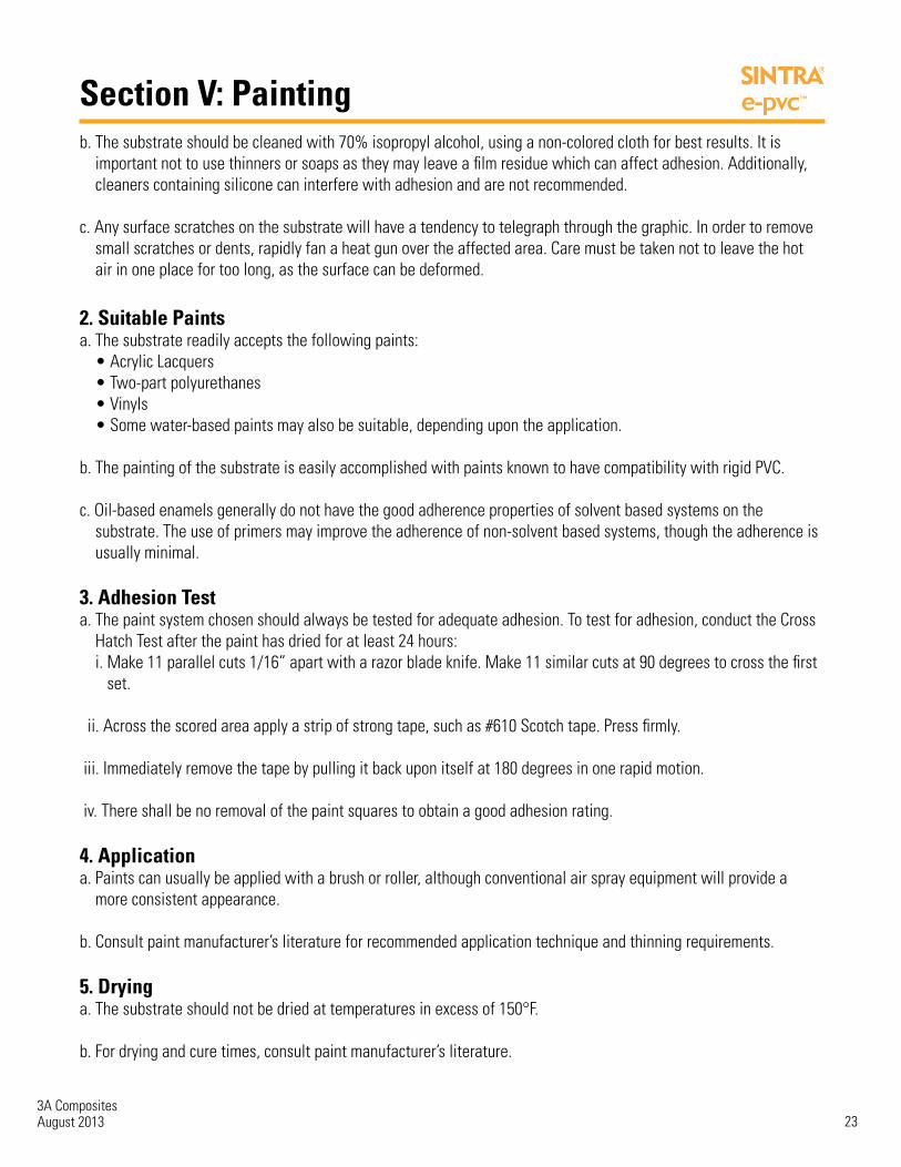
2. Suitable Paintsa. The substrate readily accepts the following paints: • Acrylic Lacquers • Two-part polyurethanes • Vinyls • Some water-based paints may also be suitable, depending upon the application.
b. The painting of the substrate is easily accomplished with paints known to have compatibility with rigid PVC.
c. Oil-based enamels generally do not have the good adherence properties of solvent based systems on the substrate. The use of primers may improve the adherence of non-solvent based systems, though the adherence is usually minimal.
3. Adhesion Testa. The paint system chosen should always be tested for adequate adhesion. To test for adhesion, conduct the Cross Hatch Test after the paint has dried for at least 24 hours: i. Make 11 parallel cuts 1/16” apart with a razor blade knife. Make 11 similar cuts at 90 degrees to cross the first set. ii. Across the scored area apply a strip of strong tape, such as #610 Scotch tape. Press firmly. iii. Immediately remove the tape by pulling it back upon itself at 180 degrees in one rapid motion. iv. There shall be no removal of the paint squares to obtain a good adhesion rating.
4. Applicationa. Paints can usually be applied with a brush or roller, although conventional air spray equipment will provide a more consistent appearance.
b. Consult paint manufacturer’s literature for recommended application technique and thinning requirements.
5. Dryinga. The substrate should not be dried at temperatures in excess of 150°F.
b. For drying and cure times, consult paint manufacturer’s literature.

3A CompositesAugust 2013 24
Section V: Painting c. Due to the wide variety of paint products on the market, and the fact that some paints have been known to embrittle or bow the substrate, testing is recommended for the initial use of any coating system before commercialization.
6. Edge Treatmenta. When the substrate is cut to size during fabrication, edge cells are exposed. Although these cells do not allow paint or water to be absorbed any further than the first layer, the filling or chemical collapsing of these cells before painting can offer close to the same texture or appearance as the substrate surface after painting. i. Filling exposed cells (10-13 mm) 1. Spot putty or glazing compound used in the auto body industry works very well. 2. Fill edge cells with spot putty using a stiff, flat blade. Fill the cells; do not build up the edge.
3. When dry, usually 3-4 minutes, sand lightly to remove blade marks and any build up of putty.
ii. Collapsing exposed cells (1-6 mm) 1. Use a PVC solvent such as, Methyl Ethyl Ketone (MEK) or Tetrahydrofuran (THF).
2. Sand the substrate edge to remove all saw or router marks.
3. Apply PVC solvent to sanded edge with acrylic glue applicator bottle. With protected finger, rub solvent onto edge of the substrate. The more you apply and rub, the more cells you collapse.
iii. Edge Banding 1. For thicker substrate gauges, 1mm or 2mm Sintra material can be adhered to the edge using a PVC solvent.
b. Aluminum or plastic edge extrusions (“U” Channels, T-Moldings)

3A CompositesAugust 2013 25
Section V: Painting

3A CompositesAugust 2013 26
Section V: Painting

3A CompositesAugust 2013 27
Section VI: Cutting
Cutting – General Notes:There are many different methods in which “cutting” can be accomplished. This guide focuses on five primary cutting methods: • Knife Cutting • Shearing • Saw Cutting • Routing • Die Cutting/Punching
When necessary, laying out a pattern on the surface of the substrate is best achieved with a soft pencil.
1. Knife CuttingThe substrate in thicknesses from 1mm to 3mm can be fabricated by this method.
The substrate can be cut by hand with mat knives, utility knives, and razor blades. Mat cutters make smooth, excellentcuts, either right-angled or beveled. Cardboard and glass cutters also work well. The key to getting a smooth, clean cut is to use a very sharp thin blade held at as low an angle as possible to the board, which reduces friction. If a straight-edge is being used as a guide, it may be practical to make the cut in more than one pass.
2. Shearing(Sintra) Shearing with a guillotine shear is generally not recommended since the material is subjected to strong compression during the shearing process. This may result in an unsatisfactory cutting edge.
3. Saw Cutting(SINTRA) Cutting the substrate may utilize the following techniques: Sheets can be cut with hand, circular or saber saws. Wood-cutting saws can also be used. Fine-tooth hack-saws are not suitable since the finer tooth spacing createsexcessive friction and produces an undesirable finish. For best results, in all cases, use saw blades that are identified astriple chip tooth configuration or “plastic cutting.”
1. Problemshooting with Sawing Should rough edges result, it may be from one or more of the following reasons: a. Dull cutting tool. b. Inadequate support of the work piece.

3A CompositesAugust 2013 28
Section VI: Cutting c. Saws not adjusted closely to work, get weave of the blade.
d. Vibration of the cutting tool.
e. High friction temperature on the cutting surface.
2. Milling a. The substrate can be machined on the usual types of milling machines: universal, horizontal and vertical. To avoid indenting the surface when clamping, place flat pieces of wood or plastic between the work and the clamps.
b. Tool geometry and working conditions are summarized in the chart below.
3. Edge Finishing a. Smooth edges can be achieved with a file, plane or sander. Conventional tools and methods for working wood or plastics can be utilized. Edges can be polished with solvent. More information on this topic is in the painting section.
4. Surface Finishing a. Short bursts of hot air from a heat gun can be used to remove small surface scratches and small dents. b. Surface finishing with cutting tools is possible. Grinding or polishing is not recommended since this may damage the surface and expose cut cells.

3A CompositesAugust 2013 29
Section VI: Cutting
4. RoutingStationary or hand routers can be used for slotting, beveling, rabbeting,rounding edges and trimming. Best cutting results are obtained withcarbide-tipped router bits. Routing, as a preparation for folding andheat bending, requires special shaped router bits. This information isincluded in “Heat Bending.” Specifications and working conditions arelisted in the chart below.

3A CompositesAugust 2013 30
Section VI: Cutting
5. Die Cutting/PunchingDie cutting and/or Punching is a method for the rapid production of flat shapes or cutouts. Typical applications wouldinclude the die cutting of: • Letters and shapes. • Openings in a sheet used as part of an assembly • Puzzle pieces
Die cutting and punching processes are similar in that they both can provide a curved shape by cutting through a substrate. Die cutting, however, uses one steel rule die that comes in contact with a flat platen, whereas, a punch has two designed shapes, a male and a female that cut the shape when pressed together.
Die cutting is typically used with lighter weight paper or foam type materials, where punches are used for heavier materials.
Prior to die cutting, the substrate can be painted or screen printed. After die cutting, the pieces may have additionalfabrication including: heat bending, fastening, gluing, routering or machining
1. A Note on Punching a. The substrate does not require “punching” tools, as die cutting works very well up to 5mm thicknesses; please refer to the previous section on die cutting. 2. Steel Rule Die Cutting Process a. The key elements to consider when die cutting are: the substrate, the press, the steel rules, and the ejection rubber. Each of these elements must be selected properly to yield satisfactory results.
b. Although various methods such as using punches and “high-dies” are applicable to die cutting the substrate, cutting with steel rule dies (SRD) is the most common.
c. SRD work basically the same way as a cookie cutter. They are made of a 1”-wide strip steel with one pre-sharpened edge. The cut strips are called “rules.” The strip steel is typically made in a thickness range of .014”–.166”. The strips are bent to the shape of the design’s trim line and held in place in a block called a “die body.”

3A CompositesAugust 2013 31
Section VI: Cutting d. In order to facilitate ejection of the part, strips of a compressible material such as neoprene are glued along the perimeter and protrude above the cutting edge of the rule. The strips can also be glued to the top or bottom platen to hold the substrate in position.
e. During die cutting, the SRD assembly is fixed under the top platen, and the substrate is placed on a steel bottom platen. Pressure is applied to force the rules of the SRD through the often preheated substrate
f. The platens are then opened and the parts removed. In some cases, additional work such as finishing the cut edge might be required. 3. Substrate Considerations a. Temperature of the Sheet i. Because the substrate is a thermoplastic material, it becomes more brittle with decreasing temperatures. With the sheet temperature below 75°F, the rule makes a clean cut about two-thirds of the way through and then fractures the last third of the cut.
ii. To get the best cut, it is advisable to preheat the material to 100°–130°F. The use of a press which contains hot platens can reduce the fracturing.
b. Thickness of the Sheet i. The quality of the die cut part is reduced as a thicker-gauge substrate is used. Beyond 5 mm, there is a greater chance of deformation, a rougher-cut surface or fracturing.
ii. It is possible to cut pieces thicker than 5 mm, providing the rule has the correct gauge (point) and bevel, the substrate is warm enough (100°–130°F), the right back-up plate is used and, most importantly, the cutting edge is kept sharp at all times. With thicker parts (5 mm+), it may be necessary to post-finish the cut edge.
iii. With a sheet thickness less than 5 mm, it is possible to form curves with radii less than 1/8”. With thicker gauges, the minimum radius must be increased. 4. Press Considerations a. The substrate is typically die cut on flat bed presses, which can be either a “moving platen” type or a “clam shell” type. Either type may be utilized without affecting the quality of the die cut.
b. The key press consideration is proper “make ready”, or preparing the press bed (anvil) to assure that the steel rule cuts evenly through the substrate without dulling the steel rules.
c. Typically, the substrate is cut on a “hard anvil.” Make ready for this type of die cutting utilizes carbon paper. The press is lowered to the point where the steel rule just touches the anvil. The places where the rule fails to touch the anvil are built up with one-mil thick shim-tape. This process is repeated until a complete imprint of the steel rule is apparent. d. Make ready is very important because the platen of the press does not necessarily close evenly. This can be caused by misalignment, uneven cutting loads or by deflection of the platen. As a rule of thumb, a four-post press will deflect one mil per foot. Steel rules that have been dulled by improper make ready will cut poorly, have increased cutting loads and can contribute to cracking problems.

3A CompositesAugust 2013 32
Section VI: Cutting e. Back-Up Plate i. One problem with steel plates is that the die might not completely penetrate the substrate which can result in fracturing at the base of the cut. An alternative to a steel plate would be to use additional substrate or chipboard as a back-up. This would allow the die to penetrate beyond the thickness of the substrate so that a cleaner cut could be obtained.
5. Steel Rule Considerations a. Steel rules are flat strips of steel with a very uniform height. One edge of the steel rule is honed to yield a cutting surface. The key properties of cutting rules are hardness, flexibility, bevel type, thickness, uniformity of height and edge preparation b. Steel rules that apply to this substrate are listed below: i. Cutting Rules 1. Cutting rules are the most common when die cutting the substrate. These rules are used to cut and pillow the edge. Cutting rules are either center bevel or side bevel, which indicates where the cutting edge is located. a) Center bevel rules result in equal forces being placed on both sides of the piece to be cut and are used when both the inside and the outside of a cut needs to be saved, e.g., as in a puzzle. This distribution of forces can be important when attempting to minimize cracking 2. Side bevel rules have one side that is essentially flat and the opposite side is sloped or beveled. The flat side should be placed toward the substrate that will be kept, with the bevel facing the scrap piece. This results in additional compressive force being placed on the scrap side. Cracking tends to be directed in this direction. c. Edge Preparation i. The edge of the steel rule can be prepared in either two methods: 1. Grinding a) Ground edge rules have micro-scratches on the cutting edge. This can result in a blade that has a reduced cutting force. b) The disadvantage of this type of rule is that it is difficult to maintain the uniform blade height. 2. Drawn Edges a) Drawn edge blades are made by drawing the blade through a die. b) This produces a uniform blade height and a smooth blade surface. ii. Although the knife has been hardened to 57-59 RC (Rockwell), after numerous die cuts, the cutting edge will become dull and may result in rough and/or incomplete cuts. Generally, it is not a good idea to resharpen the knives. Resharpening will often result in an uneven knife length. This in turn can cause uneven penetration or no penetration when the cut is made.
iii. As the rule makes contact with the substrate, you may notice strong compression which can result in a deformation or rounding of the corner.

3A CompositesAugust 2013 33
Section VI: Cutting iv. There is also a tendency to fracture the substrate about two-thirds of the way through the cut. With the same bevel, a thinner rule will produce a straighter, smoother cut and form sharper radius than a thick rule. The rule has to be thick enough, however, not to break when cutting thick substrate gauges, particularly if the temperature of the substrate is below 100°F. In general, the thinner the knife, the lower the substrate temperature required for making a cut.
v. As a guide for cutting substrate, we suggest that the following thickness (point) rules be used: 1. For normal parts, 3 point (.042”) or 4 point (.056”). 2. For intricate parts using a thin gauge (under 4 mm) substrate, 2 point (.028”). 3. For a very thick gauge (5 mm+), or if a wide cut separating adjoining pieces (some puzzles, etc.) is desired, 6 point (.084”).
d. Length of Bevel i. A long bevel will result in less deformation as the substrate is sheared. The length of the bevel is defined as the distance from the tip to the point where the honed (beveled) portion ends. The bevel should be 3/16”–1/4” in length. 4. Strippers / Ejectors a. Ejection and Stripping Rubber Ejection and stripping rubber is essential when cutting the substrate. It serves two purposes. The first purpose is to eject the part from the die after the press opens. The second purpose is to prevent cracking.
Section VII: EmbossingEmbossing – General Notes:The substrate is not recommended for this fabrication method. Please see the fabrication guide on page 11 for choosing the best recommended product.
Section VIII: Forming CurvesForming Curves – General Notes The forming of curves can be accomplished with the substrate to provide a unique dimensional effect. Curves are typicallyformed by heat forming.
Bending Through Heat FormingOne of the many advantages of the substrate is that it can easily be bent by using localized heating. It is possible to cut sheets to final dimensions and perform some machining operations prior to heat bending. Spray painting, screen printing, machining, gluing and fastening operations can be performed after heat bending.
When the above processing has been done, the part can be used in displays, signage, trade shows, or in many applications where a lightweight, curved substrate is desired. Other applications would include angles, channels and ducts.

3A CompositesAugust 2013 34
Section VIII: Forming Curves
1. Defining the Heat Bending Process a. Most rigid thermoplastic materials become soft and pliable when heated. After cooling, these materials become rigid once more. This permits a variety of heat-forming techniques such as heat bending, vacuum forming and pressure forming.
b. Unlike vacuum forming, it is not possible to create an intricate shape with heat bending. However, unlike vacuum and pressure forming, the sheet gauge of the substrate experiences relatively little thinning-out during heat bending.
c. The steps in the heat bending process are: i. Heat the substrate in an area along the line where the bend is to be made. The width of the area is determined by the gauge of the sheet and the angle of the bend.
ii. After the sheet has attained the proper flexibility, bend to obtain the desired radius and angle.
iii. Hold the substrate in position to cool. Cooling may be accelerated by contact with cold metal, a moist rag, compressed air or fans.
Heating Parameters The characteristics of the substrate, the thickness of the sheet, and the radius of the bend, will determine the method, time,temperature and width of the heated area.
1. Characteristics of the Substrate a. As a moderately expanded rigid PVC, the substrate requires less time to heat than solid materials. For optimum bending, the temperature of the substrate should be in the range of 250°–300°F.
b. In general, the substrate should be allowed to “soak” (i.e., heated at a lower temperature for a longer period of time, instead of at a higher temperature for a shorter time).
2. Types of Heaters a. Direct contact heating bars can be used for 2mm - 6mm substrate thicknesses provided that the surface temperature of the bars is kept below 300°F. A higher temperature may melt the surface or leave an unsightly impression on the substrate.
b. The substrate should be set directly on the bar to get better contact. Continue heating until the substrate is pliable enough to bend.
c. To avoid direct contact heating, one may prefer to purchase or construct an IR heater recessed slightly below the surface of a table: i. Nichrome heater wires, Calrod heaters, or silicone blanket heaters work for this use.
ii. A rheostat must be used to adjust the intensity of the heat.
iii. For substrate thicknesses 3mm and thicker, the area to be bent should be heated from both sides by alternately flipping it back and forth over the heater until the sheet becomes pliable.

3A CompositesAugust 2013 35
Section VIII: Forming Curves
3. Effect of Thickness a. As the thickness of the substrate increases, so does the total volume of the sheet to be heated. For this reason, different heating methods must be used for thicker substrates than for thinner-gauge material. i. Heating time and temperature: Increase heating time approximately 75% per each 1 mm increment in thickness. Keep the temperature setting constant. ii. Application of heat: With 1mm and 2mm, heat the substrate on one side only—the side forming the inside of bend. Above 2 mm, heat either sides; or heat one side, flip over, and heat the reverse side.
4. Effect of Radiusa. The following heating widths are recommended: i. Very small radius 2 times the thickness of the substrate
ii. Average radius 3 times the thickness of the substrate
iii. Large radius 4 times the thickness of the substrate
b. To obtain very large radii, the following techniques can be used: i . Use Calrod heaters with reflectors to broaden heating area.
ii. Use hot air guns.
iii. Construct a heater to get a very wide heating area. Use a perforated steel sheet heated with gas. Drape over a waxed cardboard tube (sleek tube) to make bend.
iv. Silicone blanket heater used in conjunction with a rheostat to control heat.
c. To make very sharp bends. 1. Use a “V” groove 90 degree carbide router bit. Score the side of the sheet which forms the inside corners. Typically route about halfway through for a 90 degree corner with a slight radius.
ii. Heat the routed area until the substrate will flex easily.
iii. Bend the sheet and place in cooling guide.
iv. Apply PVC solvent to seam to add strength to the corner.

3A CompositesAugust 2013 36
Section VIII: Forming Curves
Bending/Cooling 1. Guides and Framesa. A bending guide or frame can simply be a piece of wood or metal with the correct angle required for the part.
b. To facilitate cooling, both the guide and table can be constructed of metal.
2. Bendinga. When the proper flexibility is attained, quickly remove the substrate from the heater.
b. Position and bend the heated area over the guide. If only one side is heated, the heated side forms the inside of the bend.
c. Immobilize the part in the formed position until it has cooled.
d. To test whether or not the substrate has been sufficiently heated: i. While the material is still being heated, hold one end of the sheet and flex the other end.
ii. When it flexes easily, proceed with bending.
3. Coolinga. Cooling is accomplished by ambient air or contact with a moist rag or cool metal. Fans or compressed air can also be used to facilitate the cooling process.
b. The cooling time increases with the thickness and size of the substrate.
Other Heat Bending Techniques1. In addition to conventional heat bending, one could utilize a technique called drape forming. In this procedure, the whole substrate is first heated until pliable, then clamped to a mold and allowed to cool.
2. If more sophisticated parts are desired, use a vacuum forming process.
Curving Through Cold FormingThe substrate is not recommended for this fabrication method.
3A CompositesAugust 2013 37
Appendix I: MSDS
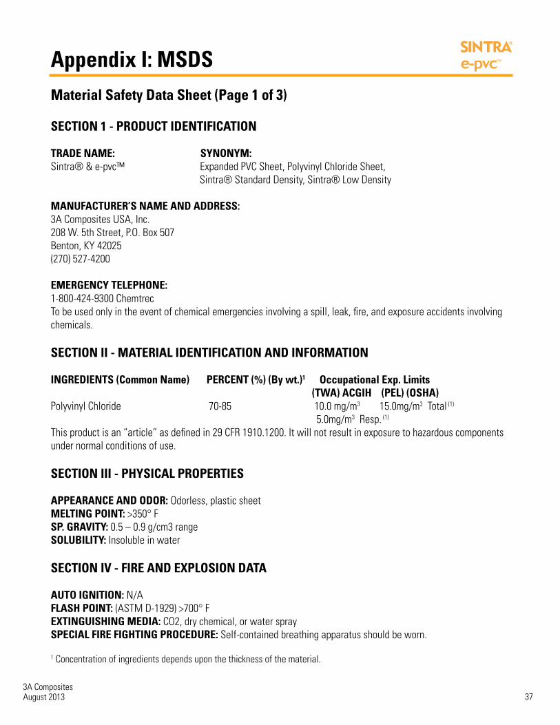
Material Safety Data Sheet (Page 1 of 3)
SECTION 1 - PRODUCT IDENTIFICATION
TRADE NAME: SYNONYM:Sintra® & e-pvc™ Expanded PVC Sheet, Polyvinyl Chloride Sheet, Sintra® Standard Density, Sintra® Low Density
MANUFACTURER’S NAME AND ADDRESS:3A Composites USA, Inc. 208 W. 5th Street, P.O. Box 507 Benton, KY 42025(270) 527-4200
EMERGENCY TELEPHONE:1-800-424-9300 ChemtrecTo be used only in the event of chemical emergencies involving a spill, leak, fire, and exposure accidents involvingchemicals.
SECTION II - MATERIAL IDENTIFICATION AND INFORMATION
INGREDIENTS (Common Name) PERCENT (%) (By wt.)1 Occupational Exp. Limits (TWA) ACGIH (PEL) (OSHA)Polyvinyl Chloride 70-85 10.0 mg/m3 15.0mg/m3 Total (1)
5.0mg/m3 Resp. (1)
This product is an “article” as defined in 29 CFR 1910.1200. It will not result in exposure to hazardous componentsunder normal conditions of use.
SECTION III - PHYSICAL PROPERTIES
APPEARANCE AND ODOR: Odorless, plastic sheetMELTING POINT: >350° FSP. GRAVITY: 0.5 – 0.9 g/cm3 rangeSOLUBILITY: Insoluble in water
SECTION IV - FIRE AND EXPLOSION DATA
AUTO IGNITION: N/AFLASH POINT: (ASTM D-1929) >700° FEXTINGUISHING MEDIA: CO2, dry chemical, or water spraySPECIAL FIRE FIGHTING PROCEDURE: Self-contained breathing apparatus should be worn.
1 Concentration of ingredients depends upon the thickness of the material.

3A CompositesAugust 2013 38
Appendix I: MSDS
Material Safety Data Sheet (Page 2 of 3)
UNUSUAL FIRE AND EXPLOSION HAZARDS: PVC will burn in the presence of supported combustion, and will emit hydrogen chloride gas, benzene, water, carbon monoxide, carbon dioxide, and smoke.
SECTION V - REACTIVITY DATA
STABILITY: Stable.INCOMPATIBILITY: None known.DECOMPOSITION PRODUCTS: Reference: “Unusual Fire and Explosion Hazards”, Section IV
SECTION VI - HEALTH HAZARD DATA
These products are not considered to be a health hazard in the form in which they are sold (sheet, panel). However, if theseproducts are abraded, melted, welded, cut or processed in any manner that causes release of fumes or dusts, hazardous levels of fumes or dusts may be generated from this product.
EFFECTS OF OVEREXPOSURE:
ACUTE: Physical irritation of the eyes may result from overexposure to high concentrations of dust from certainfabricating operations.
CHRONIC: Studies have shown that workers exposed for long periods to high concentrations of respirable PVC dust may retain the dust in their lungs. There is no evidence of a toxic response associated with such PVC dust retention.
SPECIAL INSTRUCTIONS: Avoid prolonged inhalation of high dust concentrations and ingestion of material.
Wash hands before eating, drinking or smoking.
Wear proper eye and respiratory protection when working in areas of high dust concentrations.
Care should be taken during thermoforming operations. When temperatures exceed 350° F, decomposition of the materialmay occur.
EMERGENCY AND FIRST AID PROCEDURES: If contact with eyes, wash immediately
SECTION VII - STORAGE, HANDLING, AND DISPOSAL DATA
WASTE DISPOSAL: Care must be taken when using or disposing of material debris to prevent environmental contamination. Dispose of the debris in accordance with the Clean Air Act, the Clean Water Act, the Resource Conservation and Recovery Act and all state or local laws / regulations regarding disposal.
STORAGE AND HANDLING PRECAUTIONS: Store in a flat dry area. Exercise caution in all thermal forming procedures.

3A CompositesAugust 2013 39
Appendix I: MSDS
Material Safety Data Sheet (Page 3 of 3)
SECTION VIII - PERSONAL PROTECTION DATA
PRIMARY ROUTES OF ENTRY ARE: Inhalation and ingestion
RESPIRATORY PROTECTION: An approved NIOSH/MSHA respirator must be used when engineering controls cannot be implemented to control dust concentrations. Reference OSHA 1910.134 for specific requirements.
VENTILATION: Local exhaust. Reference OSHA 1910.94 for specific requirements.
EYE: Eye protection must be worn when working in dust concentrations and during sawing or other operations which might cause flying debris. Reference OSHA 1910.133 for specific requirements.
PROTECTIVE GLOVE: Gloves should be used to prevent cuts or abrasions.
SECTION IX - REGULATORY
REACH: Pursuant to Title II article 7 of the regulation this product is exempt from registration and notification and istherefore compliant with the REACH regulation.
RoHS: Sintra® and e-pvcTM products are compliant with the RoHS standard.
IMPORTANT: The information and data contained herein are believed to be accurate and have been compiled from sourcesbelieved to be accurate. All information contained herein is offered for your consideration, information, investigation, andverification. 3A COMPOSITES MAKES NO WARRANTY OF ANY KIND, EXPRESS OR IMPLIED, CONCERNING THE ACCURACY ORCOMPLETENESS OF THE INFORMATION AND DATA HEREIN. THE IMPLIED WARRANTIES OF MERCHANTABILITY AND FITNESSFOR A PARTICULAR PURPOSE ARE SPECIFICALLY EXCLUDED. 3A Composites will not be responsible for claims relating to anyparties’ use of or reliance on information and data contained herein regardless of whether it is claimed that the information areinaccurate, incomplete, or otherwise misleading.

3A CompositesAugust 2013 40
Appendix II: Specifications
Adhesives
Selection of AdhesivesThe selection of the proper adhesive for a job depends on the materials to be joined, as well as the end use and other considerations mentioned earlier. Consulting with adhesive manufacturer and trialing adhesive method with all materials is key to success.
Fastening
Tips on Sign Installation With PostThe following data has been compiled as a general guide for the mounting of Sintra material. Unusual designs falling outside the examples given may require certain modifications when considering Sintra material.
Major Items to be Considered1. Bolt holes should always be larger than the bolt shaft to allow for thermal expansion and contraction, thus eliminating the possible stress at bolt fixing points. The use of washers spread the compressive load when bolts/ nuts are tightened. Never over-tighten — this will only weaken the connection.
2. Split timber posts are the best to use because the Sintra Material is supported evenly on both sides. If steel or aluminum poles are used, nylon bolts and washers give the best results. In all cases, never skimp on the number of fixing points. Use at least three on the average-sized sign. They should be evenly spaced and away from the top and bottom edges.
Screwed JointsFor the attachment of Sintra material, basically all known through bolts can be used. For outdoor mounting, it is recommended that the bolt shank be passed through the Sintra material in prepared holes or suitably dimensioned slots that leave adequate clearance between the bolt shank and the Sintra material (Figure 2). The screws should only be tightened firmly enough to allow the sheet to expand and contract in all directions without warping or buckling. Tapping screws or screws with form-fitted passage of the shank through the sheet should be avoided, but are allowed for interior uses with predictably low temperature variations. The diameter of the hole or length of the slot should not be less than 2.5 times the shank diameter of the fastener. Disc washers should be used to cover the holes or to bridge the slots and they should be large enough to ensure adequate load distribution. Precise centering of the screws in holes and slots is essential to permit free movement of the sheet in all directions.
FIGURE 2

3A CompositesAugust 2013 41
Appendix II: Specifications
Riveted Joints The measures that are used for screwed joints also apply to riveted joints. For this reason full rivets, whose shaft enlarges during the clenching operation so that the clearance to the hole diameter diminishes, are not suitable for outdoor mounting of Sintra material. Blind rivets (pop rivets) are suitable for fastening Sintra material to metal bases which are mounted by the drawing of aluminum or the steel mandrel.
For the United States surface temperaturedifferences of 100°-180° Fahrenheit betweenextremes (winter -30° Fahrenheit, summer +150°Fahrenheit) must be assumed in exterior usage.Dark colored sheets heat up more than light colors,if exposed to direct sunlight.
Frame Fastening of Flat Sintra Material SheetsBesides the inherent rigidity of Sintra material sheets, which is dependent on thickness, allpossible exterior stresses, e.g., wind pressure, etc., must be taken into consideration in framefastening. Dimensional changes due to thermal expansion (or contraction) must be taken intoconsideration by leaving sufficient clearance between the sheet edge and the frame.These are suspended attachment frames. Leave a space in the lower section, as well as in theside sections to allow for Sintra expansion. One pin in the middle of the rail can keep theSintra centered in the frame.
Grain DirectionSintra material is an extruded P.V.C. productand a directional grain is seen along the length ofthe sheet. Because Sintra material has a greaterflexural strength along the extrusion direction, it isalways advisable to cut signs so that the graindirection is horizontal to the post or pole fixings.This will allow Sintra material to “flex” with thewind pressure and ensure the best performance.

3A CompositesAugust 2013 42
Appendix II: Specifications
Hanging Signs Sintra material may be successfully used as interior hanging signs. As Sintra material is an extruded sheet product, thin gauges or large hanging signs may require additional support. The addition of an aluminum or thick walled plastic “C” channel across the top, bottom, or around the perimeter may be needed to alleviate any tendencies to warp. When the additions of supporting channels are not an option, the following suggestion may also be used to help prevent bowing. Holes should be located 2-1/2 times material thickness from edge.
DrillingSintra material can be drilled with conventional, high helix, high speed steel orcarbide-tipped metal bits. Quick removal of chips can be achieved by a processof high-revolution, slow-feed and occasional lifting of the drill bit. High pressureair can be used to evacuate the immediate area from chips.
Smaller drills run at faster speeds than large drills. Pressure should bereleased near the termination of through holes to prevent breakthrough.Cutting edges must be kept sharp to prevent poor surface finish andundersized holes.

3A CompositesAugust 2013 43
Appendix II: Specifications
Concealed Fastening On Brickwork of Cut-Out Advertising Letters and Figures Made Out of Sintra Material The system described here is a method of concealed fastening, not visible to the observing public. For the sake of aesthetics, acertain distance between the type print and the backing wall is often desired, whereby the system is ideally suited. The mounting is quick, easy and inexpensive.
The system consists of square mounting plates constructed out of Sintra material with an encased pin or special nail for brickwork.
1. Construct a mounting plate with Sintra Material as shown. Drill hole 2.5 times larger than shank of the pin, but smaller than the head of the pin. Apply THF solvent to upper side of mounting plate with an acrylic glue applicator bottle.
2. The treated side of the mounting plate is pressed into position of the Sintra cut-out letter and pressed firmly. Run a bead of the THF solvent around the seams of the pad and the letter and let the capillary action drag the solvent into the seam.
3. Repeat step 2 for the desired number of fastening points according to the letter type and size.
4. Mark the fastening points on the wall to be decorated. Holes, which are sufficient in diameter to hold the nail or pin, are drilled with an impact drill.
5. The holes are filled with mortar, a curable plastic material or a prime filler. The letter with the attached metal pins is then pushed into the prepared holes, holding the desired distance from the wall.

3A CompositesAugust 2013 44
Appendix II: Specifications
Outdoor Use of Sintra Material The effects of outdoor exposure on tensile, color, impact resistance and dimensional stability are as follows:
A. Color ChangesField testing reported by many Sintra material customers shows acceptable color maintenance using white, black and gray material. Other colors are not recommended for long-term exterior usage.
Colored Sintra materials are produced with organic pigments. Exterior light and some interior light fixtures emit light waves in the lower range of the light spectrum. These low range light waves may cause a fading of the Sintra material colors over time.
B. Impact Resistance and Environmental Stress 1. Effect of Temperature — With decreasing temperature, there is a tendency towards decreased impact resistance. For exterior cold weather applications with minimal framing (i.e. post signs), it is recommended to use 6mm Sintra or thicker.
2. Effect of Chemicals — Certain solvents (such as cyclohexanone) present in inks can cause environmental stress, cracking, and poor impact resistance. For this reason, the solvent systems used to dilute Screen Printing inks must be carefully chosen.

3A CompositesAugust 2013 45
Appendix II: Specifications
Thermal Expansion In the mounting or installation of Sintra material in outdoor applications or in rooms with very drastic temperature changes, the linear thermal expansion of the material has to be taken into consideration. As in all plastic materials, the sheets can warp, bulge, or inadmissible stress conditions can occur.
The linear thermal expansion of Sintra material is about the same magnitude as that of solid plastic materials, and is clearly larger than those of metals, wood and inorganic building materials like brickwork and concrete.
The dimensional change in each case depends on the expected difference between minimum and maximum temperature and the length and width of the sheet to be mounted. Appropriate values are shown in Figure 1.
FIGURE 1

3A CompositesAugust 2013 46
Appendix II: SpecificationsEXAMPLE: A printed sign board made of 6 mm strong, white Sintra material, measuring 39 in. x 98 in. is to be fastened to a wooden framework with screws of 0.196 in. shaft diameter. The sign is to be erected outdoors in a well protected and shaded place. What is the thermal expansion to be considered in mounting this sign board?
Coefficient of linear expansion for Sintra material: 0.000033 in/in/° F
Minimum temperature (winter) 5° FahrenheitMaximum temperature (summer) 140° FahrenheitInstallation temperature 70° Fahrenheit
Maximum winter temperature change (from installation) 70°- 5° = 65°Maximum summer temperature change (from installation) 140°- 70° = 70°
Calculate maximum expansion for the length of the panel.
Total contraction during winter temperatures is calculated as follows: Maximum winter temperature change x coefficient of linear expansion x sheet length = 65° x 0.000033 in/in/°F x 98 in. = 0.210 in.
Total expansion during summer temperatures is calculated in the same manner: Maximum summer temperature change x coefficient of linear expansion x sheet length = 70° x 0.000033 in/in/°F x 98 in. = 0.226 in.
For further calculations, always use the larger number, in this case, 0.226 in.
Calculate maximum expansion/contraction for the width of the panel in the same manner: Winter Summer 65° x 0.000033 in/in/°F x 39 in. = 0.08 in. 70° x 0.000033 in/in/°F x 39 in. = 0.09 in.
For further calculations, always use the larger number, in this case, 0.09 in.
HOLES:Holes diameter = Expansion/contraction + bolt shank diameter = 0.226 + 0.196 = 0.422
Diameter of holes to be drilled into the Sintra material sheet is 7/16” (0.4375) or the closest larger size to 0.422 that is available.
SLOTS:Length = Expansion/contraction + bolt shank diameter = 0.226 + 0.196 = 0.422” (7/16”)Width = Expansion/contraction + bolt shank diameter = 0.09 + 0.196 = 0.286” (5/16”)

3A CompositesAugust 2013 47
Appendix II: Specifications
Thermoforming Sintra is a slightly expanded thermoplastic sheet material which may be thermoformed by all conventional methods and techniques. Standard machines used for thermoforming work with Sintra material.
With regard to forming capability, extensibility, and detail definition, Sintra material has certain limitations. The air entrapped in the closed cells cannot be plasticized by the heat and can affect the molding and stretching of the sheet. Sintra is most suitable for large-faced and smoothly-contoured parts.
Draw ratios between 1:1 and 1:1.25 are readily attainable with Sintra. Larger ratios can be accomplished with aux-iliary equipment such as plug assist or pressure assist forming. The radius and depth of draw is generally limited to the extent that the surface of the material can stretch.
Heating Cycle Because Sintra is moderately expanded, it reacts differently than solid plastic materials and the working cycle is generally shorter. Small panel ceramic or quartz sandwich heaters are the most efficient type of heating. Care must be taken to not overheat the surfaces during the heating cycle in order to avoid degradation.
For more uniform temperature distribution, preheat Sintra material in a circulating air oven at 140° Fahrenheit.
Processing Temperatures Mold and Set Temperature: 1The Set temperature is the temperature at which the sheet hardens and can be safely removed from the mold. The closer the Mold temperature is to the Set temperature, the smaller the chance of encountering internal stress problems.
Lower Processing Limit: 2This is the lowest temperature possible for the sheet before it is completely formed. Material formed at or below this temperature could have severely increased internal stresses that later can cause warpage, and lower impact strength.
Orienting Temperature: 3Biaxially orienting the molecular structure of thermoplastic sheet approximately 275% to 300% at these tempera-tures and their cooling greatly enhances properties such as impact and tensile strength.
Normal Forming Temperature: 4This is the temperature which the sheet should reach for proper forming conditions under normal circumstances. The normal forming temperature is determined by heating the sheet to the highest temperature at which it still has enough strength to be handled, yet below the degradation temperature.
Upper Limit: 5The Upper Limit is the temperature at which the sheet begins to degrade or decompose. It is crucial to ensure that the sheet temperature stays below this temperature.

3A CompositesAugust 2013 48
Appendix II: Specifications
Simples Rules to Follow When Designing Molds 1. Make your part no bigger than absolutely necessary.2. Make the ratio of part height to part minimum width as small as possible.3. Make all outside radii and inside fillets as large as possible.4. Allow as much draft on all parts as possible.5. Always design to a reference point in the mold for trimming or hole placement.6. Mold in details, such as ribbing or domed surface, for adding stiffness.7. Design in details for positioning other components to be added.
Mold ConstructionWhen deciding between Male or Female molds one should take into account the following points:1. Which side of the part needs the detail?2. Male molds are cheaper than female molds.3. Closer tolerances can be held on male molds.4. With female molds, the flange area wall thickness is the greatest while the bottom of the cavity is the thinnest. By using a male mold, this thickness variation is just the opposite.
Additional Thermoforming TipsSintra material, provided it is stored indoors or properly sheltered, need not be dried before forming. Unlike ABS and polycarbonates, Sintra material does not absorb any hydroscopic moisture.
Plug-assist forming, using normal equipment, is necessary for more complicated shapes. Because of the lower heat capacity of Sintra material, low conductivity materials must be used for the plug.
Molds must be designed to facilitate ready flow of material. Sharp edges and narrow recesses should be avoided.Radii should not be less than 1.5 to 2 times the original sheet thickness.
Double-sided (sandwich type) heating is strongly recommended, especially for thicker sheets, Sintra material of 3 mm gauge and thicker can be thermoformed only with a double-sided heating arrangement. When heated above 150° Fahrenheit, sheets shrink slightly in the extrusion direction. Provide for the firm clamping down of sheets or for controlled slip-in.
When thermoforming colored Sintra material, deep draws combined with sharp radii may cause stress whitening, as with most PVC materials.
Storage GuidelinesSintra is to be stored inside in a dry and clean area. Material must be stored horizontal.

3A CompositesAugust 2013 49
Appendix II: Specifications

3A CompositesAugust 2013 50
Appendix II: SpecificationsSINTRA® PRODUCT SPECIFICATIONS
Definitions:
Target Thickness: The gauge that is to be focused on as optimum. The Gauge Range is then used to define the limits of the thickness that can be considered “in spec”.
Gauge Range: The upper and lower limits in thickness that a product can be manufactured making it “in spec”.Example: Target of 250mils with a range of + or - 25 mils would be 225 mils to 275 mils.
Sheet Tolerances: We measure width, length and diagonal. Width is typically cross machine, length is typically machine direction and diagonal is the difference in the diagonals.
Squareness: The difference in the lengths of the machine direction sides.
Warpage / Bow: This is the measured by laying the sheet flat on a surface and measuring the amount of “smile“ or “frown“ in the center of the board in either the length or width. Should we have a problem described as “potato chip“ this is a two direction warp, which is automatically “not in spec”.
Surface Energy (Dyne): This is measured using standard dyne solution pens
Color (∆E): This is measured using a standard color meter.
Opacity: This is measured using a standard opacity meter.
Physical Product Specifications
Target Thickness
Gauge ( + or - )
Sheet Size Tolerances
Width
<66”, Length 66” - 96”, >96”
Diagonal
Squareness (Cut Straightness)
Warpage / Bow
Surface Energy (Dyne)
Color (∆E)
Opacity
1mm
1mm
-0.05mm+ 0.25mm
0” + 1/8”
0” + 1/4”
max 1/4”
N/A
N/A
N/A
3 delta (∆E) units for Bright White and 5 for all others
N/A
2mm
2mm
+ / - 0.20mm
0” + 1/8”
0” + 1/4”
max 1/4”
N/A
N/A
N/A
3 delta (∆E) units for Bright White and 5 for all others
N/A
3mm
3mm
+ / - 0.20mm
0” + 1/8”
0” + 1/4”
max 1/4”
N/A
N/A
N/A
3 delta (∆E) units for Bright White and 5 for all others
N/A
4mm
4mm
+ / - 0.30mm
0” + 1/8”
0” + 1/4”
max 1/4”
N/A
N/A
N/A
3 delta (∆E) units for Bright White and 5 for all others
N/A
5mm
5mm
+ / - 0.35mm
0” + 1/8”
0” + 1/4”
max 1/4”
N/A
N/A
N/A
3 delta (∆E) units for Bright White and 5 for all others
N/A
6mm
6mm
+ / - 0.32mm
0” + 1/8”
0” + 1/4”
max 1/4”
N/A
N/A
N/A
3 delta (∆E) units for Bright White and 5 for all others
N/A

3A CompositesAugust 2013 51
Appendix II: Specificationse-PVC® PRODUCT SPECIFICATIONS
Definitions:
Target Thickness: The gauge that is to be focused on as optimum. The Gauge Range is then used to define the limits of the thickness that can be considered “in spec”.
Gauge Range: The upper and lower limits in thickness that a product can be manufactured making it “in spec”.Example: Target of 250mils with a range of + or - 25 mils would be 225 mils to 275 mils.
Sheet Tolerances: We measure width, length and diagonal. Width is typically cross machine, length is typically machine direction and diagonal is the difference in the diagonals.
Squareness: The difference in the lengths of the machine direction sides.
Warpage / Bow: This is the measured by laying the sheet flat on a surface and measuring the amount of “smile“ or “frown“ in the center of the board in either the length or width. Should we have a problem described as “potato chip“ this is a two direction warp, which is automatically “not in spec”.
Surface Energy (Dyne): This is measured using standard dyne solution pens
Color (∆E): This is measured using a standard color meter.
Opacity: This is measured using a standard opacity meter.
Physical Product Specifications
Target Thickness
Gauge ( + or - )
Sheet Size Tolerances
Width
<66”, Length 66” - 96”, >96”
Diagonal
Squareness (Cut Straightness)
Warpage / Bow
Surface Energy (Dyne)
Color (∆E)
Opacity
3mm
3mm
+ / - 0.20mm
0” + 1/8”
0” + 1/4”
max 1/4”
N/A
N/A
N/A
3 delta (∆E) units for
Bright White and 5
for all others
N/A
6mm
6mm
+ / - 0.32mm
0” + 1/8”
0” + 1/4”
max 1/4”
N/A
N/A
N/A
3 delta (∆E) units for
Bright White and 5
for all others
N/A
10mm
10mm
+ / - 0.60mm
0” + 1/8”
0” + 1/4”
max 1/4”
N/A
max 1/8” per foot
N/A
3 delta (∆E) units for
Bright White and 5
for all others
N/A
12.7mm
12.7mm
+ / - 0.75mm
0” + 1/8”
0” + 1/4”
max 1/4”
N/A
max 1/8” per foot
N/A
3 delta (∆E) units for
Bright White and 5
for all others
N/A

3A CompositesAugust 2013 52
This Fabrication Manual has been developed to assist fabricators to work with the substrate in the most efficient and effective manner. The tips and suggestions contained in this manual are the result of many years of combined experience by fabricators in the U.S., Canada, South America, Asia and Europe.
These fabrication suggestions and product specifications are based on information which is, in our opinion, reliable. However, since skill, judgment, and quality of equipment and tools are involved, and since conditions and methods of using the substrate are beyond our control, the suggestions contained in this manual are provided without guarantee. We recommend that prospective users determine the suitability of both the material and suggestions before adopting them on a commercial scale. 3A COMPOSITES USA, INC., DOES NOT MAKE ANY WARRANTIES, EXPRESS OR IMPLIED, INCLUDING MERCHANTABILITY AND FITNESS FOR PURPOSE, WITH RESPECT TO ANY SAID SUGGESTIONS AND PRODUCT DATA. In no event shall 3A Composites USA, Inc., have any liability in any way related to or arising out of said suggestions and product data for direct, special, consequential or any other damages of any kind regardless of whether such liability is based on breach of contract, negligence or other tort, or breach of any warranty, express or implied. Also, normal safety and health precautions practiced in any fabricating environment should be used when fabricating the substrate.
GRAPHIC DISPLAY
800.626.3365graphicdisplay.com
This product guide provides only general application information and is not intended to include all potential product uses. No express or implied warranties are contained herein. Fome-Cor®, Sintra®, Gator® and Dibond® are registered trademarks of 3A Composites USA, Inc. FiberMate™, e-pvc™ and e-panel™ are trademarks of 3A Composites USA, Inc. ©3A Composites USA, Inc. 2013. All Rights Reserved.