Embed Size (px)
Citation preview

Fabrication and Testing of ILC Cavities Produced from Seamless
Nb TubesRoy Crooks
Black Laboratories, L.L.C.Peter KneiselJefferson Lab
Contributions from:Peter Kalu, FSU/NHMFL; Anthony Rollett, CMU;Waldemar Singer, DESY; Andy Hocker, Fermilab
Bob Rimmer, Jefferson Lab; and others
The Fifth International Workshop on THIN FILMS AND NEW IDEAS FOR
PUSHING THE LIMITS OF RF SUPERCONDUCTIVITYJuly 18 – 20, 2012
Thomas Jefferson National Accelerator Facility Newport News, VA
Support for R. Crooks under DOE SBIR Grant No. DE‐FG02‐04ER83909, Fermilab, Jefferson Lab and the Virginia Center for Innovative Technology, Commonwealth Research and Commercialization Fund

LARGE SAMPLES

Advantages of seamless tube cavity production•
No RRR degradation in the welding seam •
No pits associated with the HAZ•
No weld contamination•
Lower production costs in large production runs•
Less scatter in performance compared to welded cavities(in theory)
Historical Approaches for Seamless Niobium Tube:•
Drawing or Spinning from sheet and flow forming (DESY)•
Extrusions were not adequate due to large grain size•
Spinning directly to cavity shape
(INFN)•
Heavily deformed and recrystallized fine-grain billet, Back extrusion, forward extrusion and flow-forming (BL/AWC)
Rationale and Approach, for Seamless ILC 1.3 GHz SRF Cavities

Successful fabricationof tube and hydroformedcavities
Tube is good for 3‐cells
W. Singer, DESY
INFN, DESY: Tube Making from sheet
W. Singer, DESY
DESY: Necking by Profile Ring

W. Singer, DESY
Tube Making Necking Hydroforming
DESY: Hydroforming

W. Singer, DESY
DESY: Hydroforming

Advantages: •
The metal is exposed to steady-state conditions for most of the extrusion length.
•
If a fine grained, randomly oriented starting microstructure is used, then the extrusion axisymmetric stress state should result in axisymmetric microstructure and properties.
•
The initial concept, “Production of Seamless Superconducting Radio Frequency Cavities from Ultra-fine Grained Niobium” was intended to produce a microstructure with a grain size of between 100 and 1000 nm. Luckily, that didn’t work.
•
A billet was produced with a grain size of 11 μm.
Method Used for this Program:Extruded Tube

0.00
0.01
0.02
0.03
0.04
0.05
0.06
0.07
10 20 30 40 50 60
Num
ber F
ract
ion
Misorientation Angle [degrees]
Misorientation Angle
0.0
0.1
0.2
0.3
0.4
10 20 30 40 50 60
Num
ber F
ract
ion
Misorientation Angle [degrees]
Misorientation Angle
Parameter BL/AWC Selection
ECAE
Grain size, μm
11 15
ODF max. 7.3 19
% Rx 96 7.0
% lagb 7.8 640.00
0.02
0.04
0.06
0.08
0.10
0.12
0.14
0 10 20 30 40 50 60 70
Num
ber F
ract
ion
Misorientation Angle [degrees]
Misorientation Angle
Correlated Random
MacKenzieDistribution
Selection ECAE, 4 pass + anneal
J. K. MACKENZIE, Biometrika (1958) 45 (1-2): 229-240.
Two of the processes considered, and the resulting grain boundary misorientations, recrystallization fractions and grain sizes
Experimental Billet Results

•
6.5”
billet, with fine grains and a random grain orientation was then processed to tube:–
back extrusion
–
forward extrusion–
flow forming
Tube Making
•
Expected grain size to be maintained through subsequent processing.

Flow Forming
RxRxRx
B1BB2BB1C
5 tubes ordered:
Two extrusions, B1 and B2
Final tube making step(flow forming) experimental
First tube of each extrusionused variable reduction
Tubes
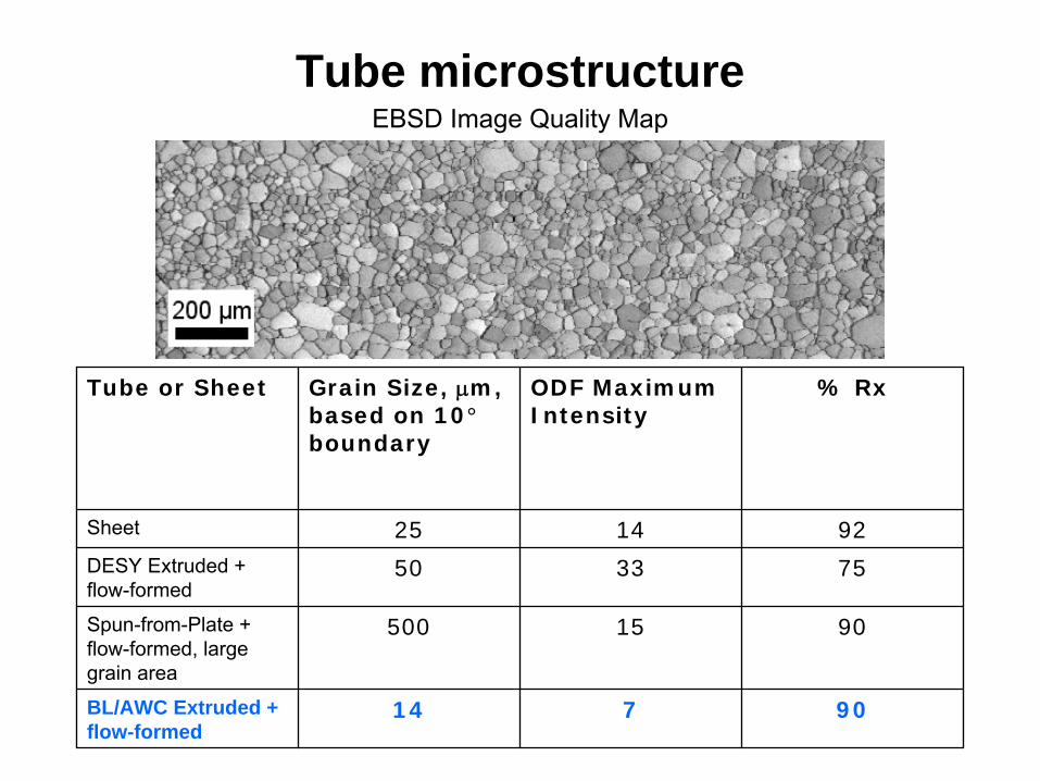
Tube or Sheet Grain Size, μm, based on 10° boundary
ODF Maximum Intensity
% Rx
Sheet 25 14 92DESY Extruded + flow-formed
50 33 75
Spun-from-Plate + flow-formed, large grain area
500 15 90
BL/AWC Extruded + flow-formed
14 7 90
Tube microstructureEBSD Image Quality Map

Dektak Profilometer data for DESY coarse-grained tube (blue) and BL/AWC fine-grained tube (red); 1kA = 0.1mm; from tensile samples near fracture. Peak to peak for AWC/BLLC tube (25) μm; for DESY coarse-grained tube (75 μm) over a length of 1 mm.
Surface RoughnessWhy fine grain is better
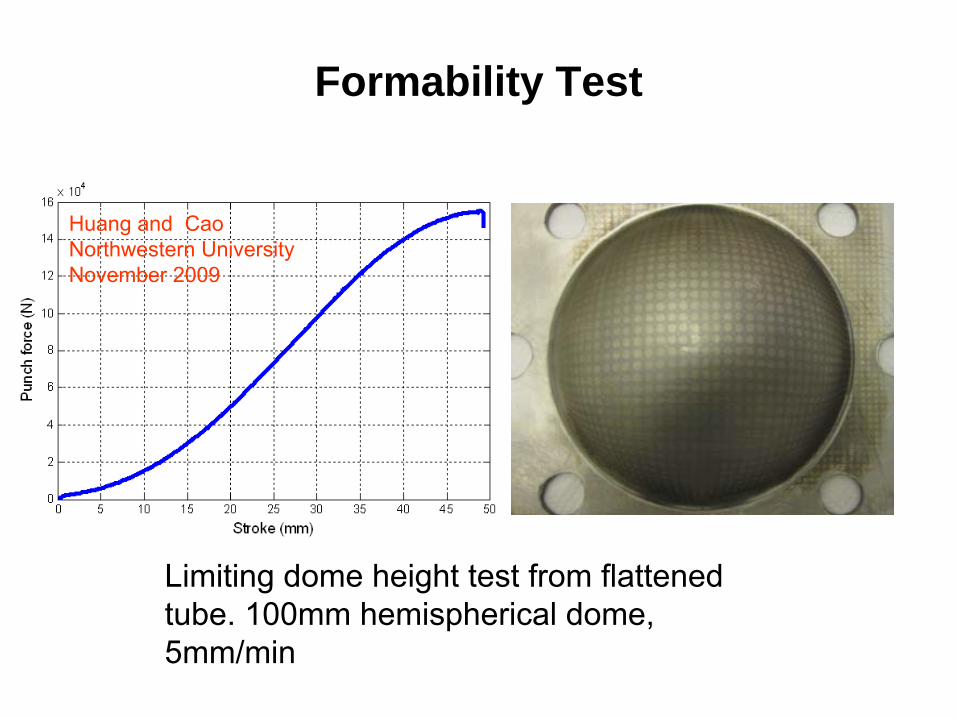
Huang and CaoNorthwestern UniversityNovember 2009
Formability Test
Limiting dome height test from flattened tube. 100mm hemispherical dome, 5mm/min

Grain size optimum? Smoother surface vs. lower ductility
YS, MPa vs 1/sqrt(d)
50
60
70
80
90
100
0 0.1 0.2 0.3
Inverse square root of (d)
YS, M
Pa
Hall-Petch Plot
AA7075Zhao et al Act mater; 52 (2004) 4859Coarse vs fine grain Nb tube
YS vs inverse sq rt grain size
for 100 nm, YS = 338 MPa
d in µm
σy
= σ0
+ Ky
(d-1/2)Nb 7075 Al

BL/AWC Tube Forming at DESY
Hydroforming
Final HydroformingStage
First Stage
Spinning
Spinning of irises Second Stage

BL/AWC/Fermi Hydroforming Results at DESY
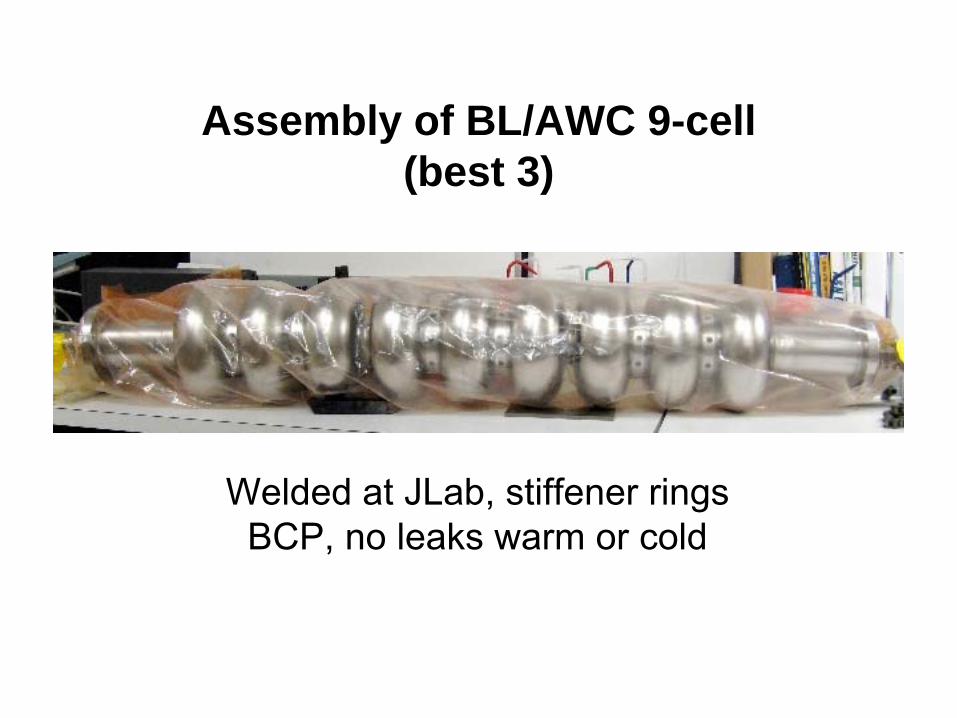
Assembly of BL/AWC 9-cell (best 3)
Welded at JLab, stiffener ringsBCP, no leaks warm or cold
SRF TestingPeter KneiselJefferson Lab
Testing has begun on:
• the 3, 3-cell hydroformed cavities selectedby Waldemar Singer for assembly
• a 2-cell piece made from surplus tube

•
Field emission limited, ~ 16 MV/m•
Problem with roughness of welds at two iris welds.
•
Similar issue with DESY 3 x 3-cell, even though 3-cells tested at 34 –
36 MV/m
•
Grinding and polishing will be used to modify
Welding of 3x3 hydroformed cells Conventional welding of deep drawn cells
(From Fermilab webpage)
9-cell test results to-date

Prepped manually before JLab facility shutdown in Spring 2012BP, HPR assembly in Class10 clean roomDid not quench at the highest gradientLimited by Q-drop –
will be barrel polished, (EP?) and retested
2-cell test
Welded at JLab

Conclusions
•
Thermomechanical treatment of the RRR niobium billet allows tube making with extrusion processes
•
Tube has been formed into ILC cavity shapes, but only in 3-cell sections, due to equipment limitations
•
Problems with weld roughness at the 3 x 3-cell junctions have shown field emission and inhibited performance
•
A 2-cell section without welds did not quench and was limited by Q-drop
•
Smoothing of welds, and further processing and testing is proceeding