Embed Size (px)
Citation preview

Easy SeriesICP-EZM2
en Troubleshooting Guide


Easy Series Table of Contents | en 3
Bosch Security Systems, Inc. Troubleshooting Guide F01U088582 | 01 | 2008.08
Table of Contents
1 Devices 71.1 Device Symptoms and Solutions 71.1.1 wLSN devices are missing. Control center does not announce "Bus device missing 50" or "Bus device
trouble 50". 71.1.2 Unable to discover wLSN device into the system. 81.1.3 Missing wLSN devices indicate a tamper condition. 81.1.4 After the exit delay expires, the system does not arm. If you then enter your passcode, the system
announces "Exit Error". 81.1.5 The system announces "Point not Ready". 91.1.6 After using the Installation Tool to confirm a good signal at all of the device installation locations, the
system cannot find all of the installed devices. 91.1.7 To allow the system to discover a smoke detector, I tested the detector by pushing its TEST button. I had
to do this three times before the system discovered the smoke detector. 101.1.8 The control center announces an "Output # AC Problem" trouble condition. 101.1.9 The relay module reports a low battery, even though the batteries are new. 101.2 Device Frequently Asked Questions (FAQs) 111.2.1 When I attempt to arm the system, it sometimes announces "Point not Ready" and at other times
announces "Exit Error". What's the difference between these announcements? 111.2.2 How do you test a relay module? 121.2.3 How do you determine the point numbers that are assigned to wLSN devices during Discovery Mode?
121.2.4 Can I prepare and power wLSN devices before an installation? 121.2.5 When I initially installed a wLSN siren or relay, I connected an external power source to it. I don't want
to use external power anymore. How do I clear the missing AC Trouble condition? 121.2.6 I forgot to activate a wLSN device during the Configuration Walk Test. How do I get the system to
discover this device? 121.2.7 I heard the control panel announce a point number during Walk Test, but did not hear that the point
number "…was tested". Why can't I make the point normal? 121.2.8 How do I know how many wLSN points were discovered by the system? 121.2.9 When should I default wLSN devices? 131.2.10 What do the wLSN device LEDs indicate? 131.2.11 What should I do if the points connected to the DX2010 do not function during a walk test? 131.2.12 What happens if someone defaults a device from a running system? 131.2.13 Why do wireless devices start from Point 9 and up after discover mode, rather than starting with Point 1?
14
2 wLSN Hub 152.1 wLSN Hub Symptoms and Solutions 152.1.1 The keypad announces "Bus device trouble 50". 152.1.2 I cannot access the Wireless Configuration menu. 152.1.3 The system announces "Bus device missing 50". 152.1.4 The system announces "Bus device tamper 50". 162.2 wLSN Hub Frequently Asked Questions (FAQs) 162.2.1 What data is stored on the wLSN Hub? 162.2.2 What do the wLSN Hub's LEDs indicate? 162.2.3 How do I configure the wLSN Hub's rotary switches? 172.2.4 How do I default the wLSN Hub? 17

4 en | Table of Contents Easy Series
F01U088582 | 01 | 2008.08 Troubleshooting Guide Bosch Security Systems, Inc.
2.2.5 Why can’t RF devices get configured in the DX2010’s zone range? 172.2.6 Why are wireless device configurations 1/2/3 not offered in the menu? 172.2.7 What happens if someone replaces a detector’s battery? 172.2.8 What happens if two separate wLSN systems within range of each other are discovered at the same time?
172.2.9 If a building has multiple Easy Series with wLSN systems installed, how do you ensure that the systems
don’t interfere with each other? 172.2.10 What happens when you delete an RF device from the system? 182.2.11 What happens when you Erase and Discover? 18
3 Radio Frequency Signal Strength (RFSS) 193.1 RFSS Symptoms and Solutions 193.1.1 The Received Signal Strength (RSS) was good at all wLSN device installation locations, but the control
panel was not able to successfully discover all devices. 193.1.2 The control center flashes and announces “Wireless receiver jammed 50”. If the Wireless Receiver
Jammed Report (Item Number 367) is enabled, the report is also sent to the central station. 203.2 RFSS Frequently Asked Questions (FAQs) 203.2.1 What do I need to do to optimize the wLSN system's reliability? 203.2.2 How do I translate the telephone menu's SNR HEX value into a decimal value? 203.2.3 Why doesn’t RFSS Mode work with some detectors? 20
4 Control Panel 214.1 Control Panel Symptoms and Solutions 214.1.1 I hear a humming noise in the telephone set when I log into the telephone menu. 214.1.2 I cannot access the Wireless Configuration menu. 214.1.3 The control panel is configured for Voice Reporting, but when the control panel calls to announce an
event, I either don't hear anything at all, or the message is cut off. 214.1.4 The control panel does not function at all. 224.2 Control Panel Frequently Asked Questions (FAQs) 224.2.1 When entering [9][9][9][9] into Menu 4, are only programmed parameters deleted from the control
panel, or is wLSN wireless data deleted too? 224.2.2 Can I program the control panel if I do not have a phone line connected to it? 224.2.3 The emergency buttons on the control center do not work. How do I activate them? 234.2.4 How do I program a duress passcode? 234.2.5 I want to use the Custom Protection feature. How do I turn it on? 244.2.6 What data is stored on the programming key? 244.2.7 What does the control panel's blue heartbeat LED indicate? 244.2.8 I hear a grumbling noise in the programming telephone. What is causing the noise? 24
5 Network Communications 255.1 Network Communications Symptoms and Solutions 255.1.1 Initialization Troubleshooting 275.1.2 Hardware Troubleshooting 275.1.3 Firmware Troubleshooting 275.1.4 Radio Registration Troubleshooting 285.1.5 SIM Troubleshooting 285.1.6 PIN Code Troubleshooting 285.1.7 Control Panel Bus Troubleshooting 285.1.8 No Authorization Troubleshooting 29
Easy Series Table of Contents | en 5
Bosch Security Systems, Inc. Troubleshooting Guide F01U088582 | 01 | 2008.08
5.1.9 Ready to Configure Troubleshooting 295.1.10 Invalid Configuration SMS Troubleshooting 295.1.11 Firmware Upload Authorization Troubleshooting 295.1.12 Remote Configuration Success Troubleshooting 305.1.13 Firmware Upload Success Troubleshooting 305.1.14 Audio Operation Troubleshooting 305.1.15 IP Operation Troubleshooting 305.1.16 Audio Off Hook Troubleshooting 305.1.17 No Incoming IP Packets Troubleshooting 315.1.18 Bus Missing Troubleshooting 315.1.19 No GSM Signal Troubleshooting 315.1.20 GSM Network Registration Troubleshooting 315.1.21 Unacceptable GSM Signal Troubleshooting 325.1.22 Initializing Radio Troubleshooting 325.1.23 Attempting Network Registration Troubleshooting 325.1.24 Unacceptable RF Signal Troubleshooting 325.1.25 Marginal RF Signal Troubleshooting 325.1.26 I'm having wireless reception issues. 335.1.27 The control panel does not communicate with Central Monitoring Station (CMS) over an Ethernet
network. 335.1.28 When I use RPS to log into the control panel with a DX4020 IP connection, I get bus device trouble for
Address 134 (DX4020 module supervision failure). 335.1.29 The control panel does not communicate with RPS using the communicator module. 345.1.30 The communicator module does not power on (no LEDs are lit). 345.2 Network Communications Frequently Asked Questions (FAQs) 355.2.1 Alarm reporting is configured on Route 1 with both a primary and a backup destination. Generating an
alarm tests only the primary route. How do I test communications to the backup destination? 35
6 System Operation 376.1 System Operation Frequently Asked Questions (FAQs) 376.1.1 Will the system work if the voice module is different than the programmed country code? 376.1.2 How do I add a user or token or key fob? 386.1.3 My token does not work when I present it to the control center. How do I fix this? 386.1.4 How do I delete a user? 386.1.5 I assigned a token to User 1 (Master User). Can I delete this token? 396.1.6 How do I replace a user's lost token or key fob? 396.1.7 How do I reset a fire point? 396.1.8 How do I configure a four-wire smoke detector? 396.1.9 Can I reset an emergency alarm? 396.1.10 Can I turn the system on if there is a malfunction, such as a loss of main power? 396.1.11 Why do I hear the siren beep during Entry Delay? 406.1.12 Why does the siren activate during a Panic alarm? 406.1.13 My history log and central station report show Point 0 and User 0. What are these? 406.1.14 The users are complaining that the control center isn’t reading the tokens at all, or it only reads a token
if the token is pressed against the control center. Is there anything that will increase the control center’s sensitivity to tokens? 40
6.1.15 I hear a grumbling noise in the programming telephone. What is causing the noise? 406.1.16 How do I perform a Direct Connect between RPS and the control panel? 406.1.17 What does it mean when the human symbol on the control center jumps back into the circle while arming

6 en | Table of Contents Easy Series
F01U088582 | 01 | 2008.08 Troubleshooting Guide Bosch Security Systems, Inc.
the zone as unoccupied? 406.1.18 Why doesn’t the system arm when there is an open point and I try to arm using my token? 416.1.19 Why doesn’t the voice transmission work correctly? 416.1.20 Why doesn’t the phone menu provide the Discovery Mode option? 416.1.21 Why can’t I configure Custom arming? 41
7 Control Center 427.1 Control Center Frequently Asked Questions (FAQs) 427.1.1 How do I set the control center's address? 427.1.2 Why doesn't the control center initialize? All I see is a flashing amber circle. 427.1.3 The control center beeps when I present a token, but nothing else happens. What's wrong? 427.1.4 Why is the control center making a buzzing noise? 427.1.5 What do the control center LEDs indicate during system startup? 437.1.6 The control center shows a broken green circle, even though all points are normal. What does this mean?
437.1.7 The users are complaining that the control center isn’t reading the tokens at all, or it only reads a token
if the token is pressed against the control center. Is there anything that will increase the control center’s sensitivity to tokens? 43
7.1.8 What should I do if the control center isn’t functional? 437.1.9 What should I do if the control center does not “speak”? 43
8 Passcodes 448.1 Passcodes Frequently Asked Questions (FAQs) 448.1.1 What are the default installer and master user passcodes? 448.1.2 Why can't I enter the Installer Menu using the installer passcode? 44
9 Error Messages 45

Easy Series Devices | en 7
Bosch Security Systems, Inc. Troubleshooting Guide F01U088582 | 01 | 2008.08
1 Devices
1.1 Device Symptoms and Solutions
Table 1.1 Device Troubleshooting Symptoms
1.1.1 wLSN devices are missing. Control center does not announce "Bus device missing 50" or "Bus device trouble 50".
Cause:Several.
Solution:Try the following actions:1. Create a tamper condition in the wLSN device and restore the device to normal
operation. Check to determine if the device returns to the system by acknowledging the fault condition at the control center.
2. Remove and replace device batteries with known good batteries, then wait 5 sec. Present your token or enter your passcode to acknowledge the fault condition at the control center.
3. Temporarily relocate the device near the wLSN Hub.4. If the device is still missing, replace the faulty device.
Section Number and Symptom Page Reference
Section 1.1.1 wLSN devices are missing. Control center does not announce "Bus device missing 50" or "Bus device trouble 50".
page 7
Section 1.1.2 Unable to discover wLSN device into the system. page 8
Section 1.1.3 Missing wLSN devices indicate a tamper condition. page 8
Section 1.1.4 After the exit delay expires, the system does not arm. If you then enter your passcode, the system announces "Exit Error".
page 8
Section 1.1.5 The system announces "Point not Ready". page 9
Section 1.1.6 After using the Installation Tool to confirm a good signal at all of the device installation locations, the system cannot find all of the installed devices.
page 9
Section 1.1.7 To allow the system to discover a smoke detector, I tested the detector by pushing its TEST button. I had to do this three times before the system discovered the smoke detector.
page 10
Section 1.1.8 The control center announces an "Output # AC Problem" trouble condition.
page 10
Section 1.1.9 The relay module reports a low battery, even though the batteries are new.
page 10
8 en | Devices Easy Series
F01U088582 | 01 | 2008.08 Troubleshooting Guide Bosch Security Systems, Inc.
1.1.2 Unable to discover wLSN device into the system.
Cause:Several, including:– Device is not deleted from the control panel– Device is not defaulted– Device batteries are low, missing, oriented incorrectly, or the battery tab was not
removed– Device is out of RF range
Solution:Try the following actions:1. Delete the desired device using the installer's wireless menu, Option 3 (Delete Wireless
Devices).2. If it is necessary to manually default a wLSN point, do so only after deleting the point
from the control panel. You can then force the system to re-discover and configure the wLSN points by executing the Add Device command from the Wireless Devices telephone menu.
3. Ensure that known good batteries are properly installed in the device, and the battery tab is removed.
4. Install the device closer to the wLSN Hub.
1.1.3 Missing wLSN devices indicate a tamper condition.
Cause:The missing and tamper conditions are latched and must be manually cleared.
Solution:If a wLSN point is missing, remove the device's cover and press and release the tamper switch to cause the device to transmit. This allows the wLSN Hub to recognize the device and restore it from the missing status. Then close the cover and clear the latched tamper and missing conditions.
1.1.4 After the exit delay expires, the system does not arm. If you then enter your passcode, the system announces "Exit Error".
Cause:A device is not normal when the exit delay expires.
Solution:– For installations that follow EN50131, the "Exit Error" message is proper operation when
a device is not normal at the end of an exit delay.– Determine and correct the faulted condition on the device.For more information, refer to Section 1.2.1 When I attempt to arm the system, it sometimes announces "Point not Ready" and at other times announces "Exit Error". What's the difference between these announcements?, page 11.
Easy Series Devices | en 9
Bosch Security Systems, Inc. Troubleshooting Guide F01U088582 | 01 | 2008.08
1.1.5 The system announces "Point not Ready".
Cause:A device is not normal when you try to arm the system.
Solution:Determine and correct the faulted condition on the device.For more information, refer to Section 1.2.1 When I attempt to arm the system, it sometimes announces "Point not Ready" and at other times announces "Exit Error". What's the difference between these announcements?, page 11.
1.1.6 After using the Installation Tool to confirm a good signal at all of the device installation locations, the system cannot find all of the installed devices.
Cause:Several, including:– Device is not deleted from the control panel– Device is not defaulted– Device batteries are low, missing, oriented incorrectly, or the battery tab has not been
removed– Device is out of RF range
Solution:Try the following actions:1. Delete the desired device using the installer's wireless menu, Option 3 (Delete Wireless
Devices).2. If it is necessary to manually default a wLSN point, do so only after deleting the point
from the control panel. You can then force the system to re-discover and configure the wLSN points by executing the Add Device command from the Wireless Devices telephone menu.
3. Ensure that known good batteries are properly installed in the device, and the battery tab is removed.
4. Check your readings with the Installation Tool. To use the Installation Tool properly, measure the signal in various locations by slowly moving the tool in several directions (up and down, left and right), holding the Installation Tool still in each location for at least 10 sec. Whenever possible, set the Installation Tool down on a surface and step back from the Tool while reading it so that your body does not affect the dB readings.If the results for SNR fluctuate significantly, the location is:– OK if you subtract the dB difference between the highest (H) result and the lowest
(L) result from the lowest (L) result, and the number equals more than 13 dB. Confirm that the location is OK by testing with the actual wireless device for this location. (L - (H - L) >= 13 dB = OK)
– Not OK if you subtract the dB difference between the highest (H) result and the lowest (L) result from the lowest (L) result and the number equals less than 13 dB. (L - (H - L) <= 13 dB = Not OK) Use the Installation Tool to find a suitable location and re-install the device.

10 en | Devices Easy Series
F01U088582 | 01 | 2008.08 Troubleshooting Guide Bosch Security Systems, Inc.
1.1.7 To allow the system to discover a smoke detector, I tested the detector by pushing its TEST button. I had to do this three times before the system discovered the smoke detector.
Solution:Press and hold the TEST button until the sounder activates.
1.1.8 The control center announces an "Output # AC Problem" trouble condition.
Cause:A wLSN output device is missing its optional external power connection.
Solution:Try the following actions:1. Find and fix the cause of the missing or low-voltage power supply to the wLSN device,
then acknowledge the tamper condition.2. If the external power connection was removed intentionally, delete the desired points
using the installer's wireless menu, Option 3 (Delete Wireless Devices); then execute the Add Device command from the Wireless Devices telephone menu.
1.1.9 The relay module reports a low battery, even though the batteries are new.
Cause:
Check if the output is permanently set. If it is, the batteries will discharge very quickly.
Solution:– Change the configuration of the output.– Provide an external power supply for the output.

Easy Series Devices | en 11
Bosch Security Systems, Inc. Troubleshooting Guide F01U088582 | 01 | 2008.08
1.2 Device Frequently Asked Questions (FAQs)
Table 1.2 Device FAQs
1.2.1 When I attempt to arm the system, it sometimes announces "Point not Ready" and at other times announces "Exit Error". What's the difference between these announcements?The system announces Point not Ready if a point is faulted at the start of exit delay.
The system announces Exit Error if a point is faulted at the end of exit delay. In Europe, the system does not arm when an Exit Error occurs.If an exit error occurred during the previous arming attempt, the control panel announces Exit Error. To clear the exit error memory, acknowledge the condition.This system behavior is controlled with system feature 159 (Start Arming with Faulted Points).
Section Number and FAQ Page Reference
Section 1.2.1 When I attempt to arm the system, it sometimes announces "Point not Ready" and at other times announces "Exit Error". What's the difference between these announcements?
page 11
Section 1.2.2 How do you test a relay module? page 12
Section 1.2.3 How do you determine the point numbers that are assigned to wLSN devices during Discovery Mode?
page 12
Section 1.2.4 Can I prepare and power wLSN devices before an installation? page 12
Section 1.2.5 When I initially installed a wLSN siren or relay, I connected an external power source to it. I don't want to use external power anymore. How do I clear the missing AC Trouble condition?
page 12
Section 1.2.6 I forgot to activate a wLSN device during the Configuration Walk Test. How do I get the system to discover this device?
page 12
Section 1.2.7 I heard the control panel announce a point number during Walk Test, but did not hear that the point number "…was tested". Why can't I make the point normal?
page 12
Section 1.2.8 How do I know how many wLSN points were discovered by the system?
page 12
Section 1.2.9 When should I default wLSN devices? page 13
Section 1.2.10 What do the wLSN device LEDs indicate? page 13
Section 1.2.11 What should I do if the points connected to the DX2010 do not function during a walk test?
page 13
Section 1.2.12 What happens if someone defaults a device from a running system?
page 13
Section 1.2.13 Why do wireless devices start from Point 9 and up after discover mode, rather than starting with Point 1?
page 14

12 en | Devices Easy Series
F01U088582 | 01 | 2008.08 Troubleshooting Guide Bosch Security Systems, Inc.
1.2.2 How do you test a relay module?There are two methods for testing a relay module:
– During initial system configuration (Test All Points), engaging or disengaging the device tamper switch causes the relay module to be enrolled into the system, and to be tested. If the input point of a Relay module is being used, the point must be faulted and then restored to be tested. (This is the same process as for other wLSN points).
– For system maintenance testing, perform a One-Button Test, or test the relay module from the telephone System Maintenance>Test menus.
1.2.3 How do you determine the point numbers that are assigned to wLSN devices during Discovery Mode?The system automatically assigns point numbers when devices are activated during the Walk
Test. You must control the sequence in which the wLSN devices are activated to control the assigned point or output number. You must use caution to ensure that no messages (low battery, faults, restorals, tampers, tamper restorals, and so on) are sent inadvertently from the devices during the initial Point Walk Test. For wLSN motion detectors, mask the detectors
until you want the system to assign their point numbers.
1.2.4 Can I prepare and power wLSN devices before an installation?Yes, but it is not recommended. wLSN devices that are not discovered by a control panel continuously attempt to locate a wLSN Hub. This process rapidly drains the batteries in the devices.For this reason, Bosch Security Systems, Inc. does not recommend installing batteries in wLSN devices until you are ready to place the system in Discovery Mode.
1.2.5 When I initially installed a wLSN siren or relay, I connected an external power source to it. I don't want to use external power anymore. How do I clear the missing AC Trouble condition?After the control panel detects external power on a wLSN device, it always expects the
external power to be present. Deleting and then Adding the device into the system clears the
condition.
1.2.6 I forgot to activate a wLSN device during the Configuration Walk Test. How do I get the system to discover this device?Add points that were not tested by using the Wireless Menu's Add Device command.
1.2.7 I heard the control panel announce a point number during Walk Test, but did not hear that the point number "…was tested". Why can't I make the point normal?For devices that have multiple inputs (for example, door-window contacts), the control panel
must learn which input to monitor. If the input was faulted but not restored, the control panel announces the point number but does not announce that it was tested. Correct this condition
by faulting and restoring the desired input during Walk Test.
1.2.8 How do I know how many wLSN points were discovered by the system?The control panel announces how many wLSN points it discovers, and repeats the announcement every 15 sec until the first device is tested.Pressing [1] while in Walk Test causes the system to announce the number of remaining devices to test, as well as the number of unconfigured devices.

Easy Series Devices | en 13
Bosch Security Systems, Inc. Troubleshooting Guide F01U088582 | 01 | 2008.08
1.2.9 When should I default wLSN devices?– When you want to install a device that was installed in a different system.– When the wLSN Hub and control panel were defaulted without deleting all devices from
the control panel first.– To assist with troubleshooting wLSN device problems.
1.2.10 What do the wLSN device LEDs indicate?Refer to Table 1.3 on page 13.
Table 1.3 wLSN Device LED Displays
1.2.11 What should I do if the points connected to the DX2010 do not function during a walk test?Power cycle the system after adding the DX2010 and configuring the points.
1.2.12 What happens if someone defaults a device from a running system?In an 868 MHz system, the system automatically brings the device back into operation.
In a 900 MHz system, you must manually rediscover the device.
wLSN Device LED Display Description
Installation Tool On Batteries fully charged.
Off Installation Tool operation on battery only.
Flashing Batteries charging.
Flashing power indicator Low battery.
PIR Motion Detector Red - fast flash Power-up (Walk Test disabled).
Red - lights for 4 sec Alarm, motion detected.
Dual Motion Detector Flashes Green to Yellow to Red Power-up (Walk Test disabled).
Green - lights for 3 sec Motion detected by microwave.
Red - lights for 4 sec Alarm, motion detected by both PIR and microwave.
Smoke Detector Flashing Flashes every 8 sec under normal operation.
On Detects smoke, sending an alarm.
Off Malfunction, replace the batteries, clean the detector, or replace the optical chamber as required.
Key Fob Flashing red LED during key fob inactivity
Replace the batteries.
Glassbreak Detector Internal alarm and event LEDs flash simultaneously every sec.
Low battery condition.Alarm and event LEDs are located behind the detector's service door.Slide the Enable LED switch to the left to enable LED activity.

14 en | Devices Easy Series
F01U088582 | 01 | 2008.08 Troubleshooting Guide Bosch Security Systems, Inc.
1.2.13 Why do wireless devices start from Point 9 and up after discover mode, rather than starting with Point 1?By default, Points 1 to 8 are enabled as on-board hard-wired points. To assign an on-board
point as a wireless point, disable the point in programming before starting the device discovery process. You can individually assign Points 1 to 8 as wireless points.

Easy Series wLSN Hub | en 15
Bosch Security Systems, Inc. Troubleshooting Guide F01U088582 | 01 | 2008.08
2 wLSN Hub
2.1 wLSN Hub Symptoms and Solutions
Table 2.1 wLSN Hub Troubleshooting Symptoms
2.1.1 The keypad announces "Bus device trouble 50".
Cause:Several, including:– The wLSN Hub's device ID does not match the expected ID, because the wLSN Hub was
replaced, the control panel was replaced, or the control panel was defaulted.– The wLSN Hub reported a hardware failure.
Solution:If the cause was the first bullet above:1. Initiate the appropriate data transfer between the wLSN Hub and the control panel by
using the Wireless Configuration Menu's Transfer options.2. You can also initiate an erase and discover process if you are installing a new system.
If the cause was the second bullet above:1. Power cycle the system.2. If the problem continues, replace the wLSN Hub.
2.1.2 I cannot access the Wireless Configuration menu.
Cause:Several.
Solution:– Ensure that the wLSN Hub's switches are set to S1=1, S2=0, S3=0.– Disarm the system to access the Wireless Configuration menu.– Check the setting for Expert Programming Item Number 142 (Restrict Installer
Passcode). If it is set to 1, you cannot access the Wireless Configuration Menu.– Connect the wLSN to the control panel.
2.1.3 The system announces "Bus device missing 50".
Cause:The wLSN Hub is not communicating correctly with the control panel.
Solution:Check the wiring between the control panel and the wLSN Hub.
Section Number and Symptom Page Reference
Section 2.1.1 The keypad announces "Bus device trouble 50". page 15
Section 2.1.2 I cannot access the Wireless Configuration menu. page 15
Section 2.1.3 The system announces "Bus device missing 50". page 15
Section 2.1.4 The system announces "Bus device tamper 50". page 16

16 en | wLSN Hub Easy Series
F01U088582 | 01 | 2008.08 Troubleshooting Guide Bosch Security Systems, Inc.
2.1.4 The system announces "Bus device tamper 50".
Cause:The wLSN Hub's cover is unlocked, or the wLSN Hub (with wall tamper) is removed from the wall.
Solution:Ensure that the wLSN Hub cover is locked, the wLSN Hub is securely mounted to the wall, and the tamper condition is acknowledged.
2.2 wLSN Hub Frequently Asked Questions (FAQs)
Table 2.2 wLSN FAQs
2.2.1 What data is stored on the wLSN Hub?All wLSN device IDs and configuration data are stored in the wLSN Hub. A duplicate set is
stored in the control panel, which allows you to replace either the control panel or the wLSN
Hub without having to rediscover devices.
2.2.2 What do the wLSN Hub's LEDs indicate?Refer to Table 2.3 on page 16.
Table 2.3 wLSN HUB LED Displays
Section Number and FAQ Page Reference
Section 2.2.1 What data is stored on the wLSN Hub? page 16
Section 2.2.2 What do the wLSN Hub's LEDs indicate? page 16
Section 2.2.3 How do I configure the wLSN Hub's rotary switches? page 17
Section 2.2.4 How do I default the wLSN Hub? page 17
Section 2.2.5 Why can’t RF devices get configured in the DX2010’s zone range?
page 17
Section 2.2.6 Why are wireless device configurations 1/2/3 not offered in the menu?
page 17
Section 2.2.7 What happens if someone replaces a detector’s battery? page 17
Section 2.2.8 What happens if two separate wLSN systems within range of each other are discovered at the same time?
page 17
Section 2.2.9 If a building has multiple Easy Series with wLSN systems installed, how do you ensure that the systems don’t interfere with each other?
page 17
Section 2.2.10 What happens when you delete an RF device from the system?
page 18
Section 2.2.11 What happens when you Erase and Discover? page 18
Operation LED Display
Self Test and Hardware Failure LED flashes twice per sec. This indicates failure. The wLSN Hub does not operate.
Standard Operation LED on.
Configuring Network LED flashes once every 2 sec.
RFSS Mode LED flashes once every 4 sec.

Easy Series wLSN Hub | en 17
Bosch Security Systems, Inc. Troubleshooting Guide F01U088582 | 01 | 2008.08
2.2.3 How do I configure the wLSN Hub's rotary switches?Refer to Figure 2.1 on page 17.
Figure 2.1 wLSN Hub Switch Settings
2.2.4 How do I default the wLSN Hub?1. Remove the hub from the base.2. Make note of the current rotary switch settings, and then set the switches as follows:
S1 = 9, S2 = 8, S3 = 7. Refer to Figure 2.1 on page 17.3. Reconnect the hub to its base.4. Wait for the hub’s green LED to light and then go dark (approximately 5 sec).5. Disconnect the hub, then reset the rotary switches to the original settings.6. Default the control panel.7. Reconnect the hub to its base.8. Return all devices to an undiscovered state.
2.2.5 Why can’t RF devices get configured in the DX2010’s zone range?As soon as a DX2010 Expander Module is connected to the control panel, all eight zones in the
expander module’s range automatically become unavailable for wireless points.
2.2.6 Why are wireless device configurations 1/2/3 not offered in the menu?The wireless data between the control panel and the wLSN Hub are different. Transfer data
from the control panel to the wLSN Hub, or from the wLSN Hub to the control panel.
2.2.7 What happens if someone replaces a detector’s battery?The system automatically starts using the device again.
2.2.8 What happens if two separate wLSN systems within range of each other are discovered at the same time?The systems discover and learn each other’s devices.
To avoid this, discover only one system at a time.
2.2.9 If a building has multiple Easy Series with wLSN systems installed, how do you ensure that the systems don’t interfere with each other?Leave the system(s) that were installed first running while you place the latest system into
discovery mode. This guarantees that the new system chooses the best possible frequency that will avoid interference with the existing systems.
1 - Normal Operation (S1 = 1, S2 = 0, S3 = 0)
2 - RFSS Mode (S1 = 9, S2 = 2, S3 = 0)
3 - Default wLSN Hub (S1 = 9, S2 = 8, S3 = 7)
0
5
0
5
0
5
S1 S2 S3
0
5
0
5
0
5
S1 S2 S3
0
5
0
5
0
5
S1 S2 S3
1 2 3

18 en | wLSN Hub Easy Series
F01U088582 | 01 | 2008.08 Troubleshooting Guide Bosch Security Systems, Inc.
2.2.10 What happens when you delete an RF device from the system?When you delete an RF-device from the system, the wLSN Hub returns device to factory
default status. If you put the system into discovery mode, the system re-learns the device unless you remove its batteries.
2.2.11 What happens when you Erase and Discover?The system erases all discovered points from the panel and wLSN Hub. You must then:
1. Manually default and rediscover the detectors. 2. Reprogram all zone-specific parameters.

Easy Series Radio Frequency Signal Strength (RFSS) | en 19
Bosch Security Systems, Inc. Troubleshooting Guide F01U088582 | 01 | 2008.08
3 Radio Frequency Signal Strength (RFSS)
3.1 RFSS Symptoms and Solutions
Table 3.1 RFSS Troubleshooting Symptoms
3.1.1 The Received Signal Strength (RSS) was good at all wLSN device installation locations, but the control panel was not able to successfully discover all devices.
Cause:Several, including:– Device was not removed from the control panel– Device is not defaulted– Device batteries are low, missing, or the battery tab was not removed– Device is out of RF range
Solution:Try the following actions:1. Delete the desired device using the installer's wireless menu, Option 3 (Delete Wireless
Devices).2. If it is necessary to manually default a wLSN point, do so only after deleting the point
from the control panel. You can then force the system to rediscover and configure the wLSN points by executing the Add Device command from the Wireless Devices telephone menu.
3. Ensure that known good batteries are properly installed in the device, and the battery tab is removed.
4. Check your readings with the Installation Tool. To properly use the Installation Tool, measure the signal in various locations by slowly moving the tool in several directions (up and down, left and right), holding the Installation Tool still in each location for at least 10 sec. Whenever possible, place the Installation Tool on a surface and step back from the Tool while reading it so that your body does not affect the dB readings.If the results for SNR fluctuate significantly, the location is:– OK if you subtract the dB difference between the highest (H) result and the lowest
(L) result from the lowest (L) result, and the number equals more than 13 dB. Confirm that the location is OK by testing with the actual wireless device for this location. (L - (H - L) >= 13 dB = OK)
– Not OK if you subtract the dB difference between the highest (H) result and the lowest (L) result from the lowest (L) result and the number equals less than 13 dB.(L - (H - L) <= 13 dB = Not OK) Use the Installation Tool to find a suitable location and re-install the device.
Section Number and Symptom Page Reference
Section 3.1.1 The Received Signal Strength (RSS) was good at all wLSN device installation locations, but the control panel was not able to successfully discover all devices.
page 19
Section 3.1.2 The control center flashes and announces “Wireless receiver jammed 50”. If the Wireless Receiver Jammed Report (Item Number 367) is enabled, the report is also sent to the central station.
page 20

20 en | Radio Frequency Signal Strength (RFSS) Easy Series
F01U088582 | 01 | 2008.08 Troubleshooting Guide Bosch Security Systems, Inc.
3.1.2 The control center flashes and announces “Wireless receiver jammed 50”. If the Wireless Receiver Jammed Report (Item Number 367) is enabled, the report is also sent to the central station.
Cause:The signal between the wLSN Hub and a wLSN device is weak, causing the Hub to report the device missing intermittently. The control panel interprets this behavior as jamming event at the wLSN Hub.
Solution:– If a device has reported missing, that is probably the device causing this symptom. Install
that device in a different location that provides a stronger signal with the wLSN Hub.– If the system had been working reliably and this is a new problem, determine if anything
has changed in the home that is generating new RF interference.
3.2 RFSS Frequently Asked Questions (FAQs)
Table 3.2 RFSS FAQs
3.2.1 What do I need to do to optimize the wLSN system's reliability?SNR and RSS are the key to wLSN reliability. Installing wLSN devices in locations that would require radio signals to pass through materials such as cement, brick, stone, or metal decreases system reliability. Whenever possible, install the wLSN Hub and the wLSN devices on the same side of walls made from these materials. Also, do not install the wLSN Hub within 15 cm (6 in.) of the control panel's metal enclosure.
3.2.2 How do I translate the telephone menu's SNR HEX value into a decimal value?Multiply the first digit x 16, then add the second digit.The HEX values are:– A = 10– B = 11– C = 12– D = 13– E = 14– F = 15For example, if the telephone menu's SNR HEX value is 2A, then:(2 x 16) + 10 = 42.
3.2.3 Why doesn’t RFSS Mode work with some detectors?RFSS Mode only works with defaulted devices, which therefore the system has not discovered.
Section Number and FAQ Page Reference
Section 3.2.1 What do I need to do to optimize the wLSN system's reliability?
page 20
Section 3.2.2 How do I translate the telephone menu's SNR HEX value into a decimal value?
page 20
Section 3.2.3 Why doesn’t RFSS Mode work with some detectors? page 20

Easy Series Control Panel | en 21
Bosch Security Systems, Inc. Troubleshooting Guide F01U088582 | 01 | 2008.08
4 Control Panel
4.1 Control Panel Symptoms and Solutions
Table 4.1 Control Panel Troubleshooting Symptoms
4.1.1 I hear a humming noise in the telephone set when I log into the telephone menu.
Cause:The power supply does not have proper earth ground.
Solution:Make sure the Easy Series power supply is wired to proper earth ground using appropriate cable. This will provide proper system performance, and will improve installer and customer safety.
4.1.2 I cannot access the Wireless Configuration menu.
Cause:Several.
Solution:– Make sure the wLSN Hub's switches are set to S1=1, S2=0, S3=0.– You cannot access the Wireless Configuration menu if the system is armed.– If Expert Programming Item Number 142 (Restrict Installer Passcode) is set to 1, you cannot
access the Wireless Configuration Menu.– Make sure the wLSN Hub is connected to the control panel.
4.1.3 The control panel is configured for Voice Reporting, but when the control panel calls to announce an event, I either don't hear anything at all, or the message is cut off.
Cause:The voice message repeat count is too low, so the control panel is partially or completely through the message before you answer the telephone.
Solution:Increase the repeat count for voice messages.
Section Number and Symptom Page Reference
Section 4.1.1 I hear a humming noise in the telephone set when I log into the telephone menu.
page 21
Section 4.1.2 I cannot access the Wireless Configuration menu. page 21
Section 4.1.3 The control panel is configured for Voice Reporting, but when the control panel calls to announce an event, I either don't hear anything at all, or the message is cut off.
page 21
Section 4.1.4 The control panel does not function at all. page 22

22 en | Control Panel Easy Series
F01U088582 | 01 | 2008.08 Troubleshooting Guide Bosch Security Systems, Inc.
4.1.4 The control panel does not function at all.
Cause:Several.
Solution:Check the following:– If no LEDs are lit, check the power wiring.– If the blue heartbeat LED flashes five times, the telephone is active.– If the red LED flashes, there is an error. Call Bosch Security Systems technical support
for help identifying the meaning of the red LED flashes.– Make sure the control panel’s backup battery is not deep discharged.
4.2 Control Panel Frequently Asked Questions (FAQs)
Table 4.2 Control Panel FAQs
4.2.1 When entering [9][9][9][9] into Menu 4, are only programmed parameters deleted from the control panel, or is wLSN wireless data deleted too?All programming data, including the wireless data, is deleted.
4.2.2 Can I program the control panel if I do not have a phone line connected to it?Yes. Follow these steps:1. Connect a test telephone to the phone set posts or house phone terminals on the control
panel board.2. Press and hold the system test button for approximately 15 sec.3. Enter the installer passcode when prompted.
Section Number and FAQ Page Reference
Section 4.2.1 When entering [9][9][9][9] into Menu 4, are only programmed parameters deleted from the control panel, or is wLSN wireless data deleted too?
page 22
Section 4.2.2 Can I program the control panel if I do not have a phone line connected to it?
page 22
Section 4.2.3 The emergency buttons on the control center do not work. How do I activate them?
page 23
Section 4.2.4 How do I program a duress passcode? page 23
Section 4.2.5 I want to use the Custom Protection feature. How do I turn it on?
page 24
Section 4.2.6 What data is stored on the programming key? page 24
Section 4.2.7 What does the control panel's blue heartbeat LED indicate? page 24
Section 4.2.8 I hear a grumbling noise in the programming telephone. What is causing the noise?
page 24

Easy Series Control Panel | en 23
Bosch Security Systems, Inc. Troubleshooting Guide F01U088582 | 01 | 2008.08
4.2.3 The emergency buttons on the control center do not work. How do I activate them?By default, the emergency buttons are turned off. Follow these steps to turn them on:1. Start a phone session.2. Enter the installer passcode.3. Press [4] to select Expert Programming.4. Enter the following expert programming item numbers, and change the setting for each
button:– 888 = fire alarm (0 = disabled, 1 = fire alarm)– 889 = medical alarm (0 = disabled, 1 = medical alarm)– 890 = panic alarm (0 = disabled, 1 = audible panic alarm, 2 = silent panic alarm)
5. Ensure that the following reports are enabled:– 319 = user emergency (1 = Route 1 only, 2 = Route 2 only, 3 = both routes)– 320 = user fire (1 = Route 1 only, 2 = Route 2 only, 3 = both routes)– 322 = user panic (1 = Route 1 only, 2 = Route 2 only, 3 = both routes)
6. Press [#] repeatedly until you hear the system say "goodbye." The buttons are now active.
4.2.4 How do I program a duress passcode?Follow these steps:1. Start a phone session.2. Enter the installer passcode.3. Press [4] to select Expert Programming.4. Press [8][6][2] to select Expert Programming Item Number 862, and then press [1] to
enable the duress user (User 22).By default, the duress passcode is "1111" if the passcode length = 4 digits, or "111111" if the passcode length = 6 digits.
5. Press [#] until you hear the system say "goodbye."6. Start a new phone session.7. Enter the master user passcode.8. Press [4] to select the User Menu.9. Press [2] to change a user.10. Press [2] repeatedly to scroll through all available users until you reach User 22.11. Press [1] to select User 22.12. Press [3] to enter a new passcode.13. Enter a new passcode. Only digits 1 through 5 are allowed.
You cannot assign a token to User 22.14. Press [1] to return to User Menu selections.15. Press [#] repeatedly until you hear the system say "goodbye."
The duress user (User 22) is now active.

24 en | Control Panel Easy Series
F01U088582 | 01 | 2008.08 Troubleshooting Guide Bosch Security Systems, Inc.
4.2.5 I want to use the Custom Protection feature. How do I turn it on?Follow these steps:1. Start a phone session.2. Enter the installer passcode.3. Press [4] to select Expert Programming.4. Enter the appropriate expert programming item number.
Use Expert Programming Item Numbers 9013 to 9323 to set the Custom Protection option for each desired point.The middle digits = the point number. For example, "01" = Point 1, and "32" = Point 32.– For Point 1, press [9][0][1][3].– For Point 2, press [9][0][2][3].– For Point 3, press [9][0][3][3].– For Point 10, press [9][1][0][3].– For Point 20, press [9][2][0][3].– For Point 32, press [9][3][2][3].
5. Press [1] to include the point in Custom Protection.24-Hour, Fire Verified, Fire Instant, and Panic points always create alarm conditions regardless of the selected protection mode.
6. Repeat Steps 4 and 5 to include additional points in Custom Protection.7. Press [#] repeatedly until you hear the system say "goodbye."
Custom Protection is now an active protection mode selection. Only the points selected in Steps 4 and 5 turn on when you turn on the system in Custom Protection mode.Custom protection points also turn on when you turn on the system as either Occupied or Unoccupied.
4.2.6 What data is stored on the programming key?All control panel and wLSN configuration data is backed up onto the programming key, except for the voice data which is stored in the Voice Module.
4.2.7 What does the control panel's blue heartbeat LED indicate?The blue heartbeat LED flashes slowly to indicate normal operation. The blue LED flashes five times quickly when the telephone is in use.
4.2.8 I hear a grumbling noise in the programming telephone. What is causing the noise?This symptom occurs when the system does not have a good earth ground. Ensure that the control center has a good earth ground.

Easy Series Network Communications | en 25
Bosch Security Systems, Inc. Troubleshooting Guide F01U088582 | 01 | 2008.08
5 Network Communications
5.1 Network Communications Symptoms and SolutionsIf your system uses an ITS-DX4020-G GPRS/GSM Integrated Communicator module, refer to the module’s LED descriptions shown in Table 5.1 starting on page 25 before performing any troubleshooting procedures.If Table 5.1 does not provide the troubleshooting information you need, refer to Table 5.2 on page 27.
Table 5.1 ITS-DX4020-G LED Descriptions
LED State
Operating Mode STATUS CELL IP AUDIO SS1 SS2 SS3 BUS Information and
Troubleshooting Section
Powering on and
initialization mode Double
flash
Off Off Off Off Off Off Section 5.1.1 Initialization
Troubleshooting, page 27.
Unrecoverable
problem
Double
flash
Double
flash
Off Off Off Off Off Section 5.1.2 Hardware
Troubleshooting, page 27.
Double
flash
Off Double
flash
Off Off Off Off Section 5.1.3 Firmware
Troubleshooting, page 27.
Double
flash
Off Off Double
flash
Off Off Off Section 5.1.4 Radio Registration
Troubleshooting, page 28.
Double
flash
Off Off Off Double
flash
Off Off Section 5.1.5 SIM
Troubleshooting, page 28.
Double
flash
Off Off Off Off Double
flash
Off Section 5.1.6 PIN Code
Troubleshooting, page 28.
Double
flash
Off Off Off Off Off Double
flash
Section 5.1.7 Control Panel Bus
Troubleshooting, page 28.
Configuration
mode (J200
jumper installed)
→ → → See Signal strength indicators
section of table below.
Off Section 5.1.8 No Authorization
Troubleshooting, page 29.
→ → → See Signal strength indicators
section of table below.
On Section 5.1.9 Ready to Configure
Troubleshooting, page 29.
→ → → Flash Flash Flash Flash Section 5.1.10 Invalid
Configuration SMS
Troubleshooting, page 29.
→ → → Double
flash
Double
flash
Double
flash
Double
flash
Section 5.1.11 Firmware Upload
Authorization Troubleshooting,
page 29.
→ → → → → → → Section 5.1.12 Remote
Configuration Success
Troubleshooting, page 30.
Shifting
flash
Shifting
flash
Shifting
flash
Shifting
flash
Shifting
flash
Shifting
flash
Shifting
flash
Section 5.1.13 Firmware Upload
Success Troubleshooting, page 30.
Key:
→ = Scrolling LEDs, from left to right.
⊗ = LED’s status does not matter.
Shifting flash = Every other LED flashes simultaneously, creating the shifting flash pattern.

26 en | Network Communications Easy Series
F01U088582 | 01 | 2008.08 Troubleshooting Guide Bosch Security Systems, Inc.
Standard
operating mode
On Off On or off See Signal strength indicators
section of table below.
On Section 5.1.14 Audio Operation
Troubleshooting, page 30.
On On On or off See Signal strength indicators
section of table below.
On Section 5.1.15 IP Operation
Troubleshooting, page 30.
On ⊗ On See Signal strength indicators
section of table below.
On Section 5.1.16 Audio Off Hook
Troubleshooting, page 30.
Transitional/watch
states
Flash Flash On or off See Signal strength indicators
section of table below.
On Section 5.1.17 No Incoming IP
Packets Troubleshooting, page 31.
Flash ⊗ On or off See Signal strength indicators
section of table below.
Flash Section 5.1.18 Bus Missing
Troubleshooting, page 31.
Flash ⊗ ⊗ Off Off Off ⊗ Section 5.1.19 No GSM Signal
Troubleshooting, page 31.
Flash Off ⊗ Flash Off Off ⊗ Section 5.1.20 GSM Network
Registration Troubleshooting,
page 31.
Flash ⊗ ⊗ On Off Off ⊗ Section 5.1.21 Unacceptable GSM
Signal Troubleshooting, page 32.
Signal strength
indicators
⊗ ⊗ ⊗ Off Off Off ⊗ Section 5.1.22 Initializing Radio
Troubleshooting, page 32.
⊗ ⊗ ⊗ Flash Off Off ⊗ Section 5.1.23 Attempting
Network Registration
Troubleshooting, page 32.
⊗ ⊗ ⊗ On Off Off ⊗ Section 5.1.24 Unacceptable RF
Signal Troubleshooting, page 32.
⊗ ⊗ ⊗ On Flash Off ⊗ Section 5.1.25 Marginal RF Signal
Troubleshooting, page 32.
⊗ ⊗ ⊗ On On Off ⊗ Good signal strength: -83 dBm to
-77 dBm. No corrective action
required.
⊗ ⊗ ⊗ On On Flash ⊗ Very good signal strength: -77
dBm to -69 dBm. No corrective
action required.
⊗ ⊗ ⊗ On On On ⊗ Excellent signal strength: > -69
dBm. No corrective action
required.
Table 5.1 ITS-DX4020-G LED Descriptions
LED State
Operating Mode STATUS CELL IP AUDIO SS1 SS2 SS3 BUS Information and
Troubleshooting Section
Key:
→ = Scrolling LEDs, from left to right.
⊗ = LED’s status does not matter.
Shifting flash = Every other LED flashes simultaneously, creating the shifting flash pattern.
Easy Series Network Communications | en 27
Bosch Security Systems, Inc. Troubleshooting Guide F01U088582 | 01 | 2008.08
Table 5.2 Network Communications Troubleshooting Symptoms
5.1.1 Initialization Troubleshooting
Description:STATUS LED double flashes until initialization is complete.
Solution:If the device stays in this state for more than 60 sec, check wiring between the communicator and the control panel, and reboot the system. If the problem continues, refer to
Section 5.1.2 Hardware Troubleshooting, page 27.
5.1.2 Hardware Troubleshooting
Description:General hardware problem.
Solution:1. Reboot the system.2. Check for broken or overheated components and short circuits. 3. Check current and voltage at the communicator’s Power input pins (16 VDC to 20 VDC). 4. If everything appears normal, replace the communicator module.
5.1.3 Firmware Troubleshooting
Description:Corrupted flash or failed firmware upload.
Solution:1. Perform the Factory Defaulting procedure as described in the Easy Series System
Reference Guide.2. Perform the firmware upload procedure as described in the Easy Series System Reference
Guide. 3. If the problem continues, replace communicator module.
Section Number and Symptom Page Reference
Section 5.1.26 I'm having wireless reception issues. page 33
Section 5.1.27 The control panel does not communicate with Central Monitoring Station (CMS) over an Ethernet network.
page 33
Section 5.1.28 When I use RPS to log into the control panel with a DX4020 IP connection, I get bus device trouble for Address 134 (DX4020 module supervision failure).
page 33
Section 5.1.29 The control panel does not communicate with RPS using the communicator module.
page 34
Section 5.1.30 The communicator module does not power on (no LEDs are lit).
page 34

28 en | Network Communications Easy Series
F01U088582 | 01 | 2008.08 Troubleshooting Guide Bosch Security Systems, Inc.
5.1.4 Radio Registration Troubleshooting
Description:Failed to register or re-register on the wireless network.
Solution:Check for RF signal strength by shorting the CONFIG jumper and reading the Signal Strength LEDs as described in the Signal strength indicators section of Table 5.1, page 25.If signal strength is unacceptable, refer to Section 5.1.26 I'm having wireless reception issues., page 33.If signal strength is acceptable, confirm that the wireless service provider has activated this
account correctly.
5.1.5 SIM Troubleshooting
Description:SIM problem.
Solution:1. Check for the presence of a SIM in the holder. 2. Remove and re-seat SIM card in the holder, checking for worn contacts or looseness
between the holder and the SIM card. 3. Reboot the system. 4. If the problem continues after rebooting the system, replace the SIM card. This will
require a new receiver account and re-configuration of the ITS-DX4020-G.
5.1.6 PIN Code Troubleshooting
Description:Mismatched PIN code.
Solution:– If the SIM’s PIN is unknown, locate the PIN using the installer account record. – If the SIM’s PIN is known, check the communicator’s configuration and make sure the PIN
matches. – If you want to make a PIN code unnecessary, locate the SIM PIN and the PIN Unlocking
Key (PUK), then reconfigure the PIN codes on the SIM and communicator module as described in the System Reference Manual.
5.1.7 Control Panel Bus Troubleshooting
Description:The ITS-DX4020-G is receiving bus packets for other devices, but is not receiving packets for itself.
Solution:1. Check for complete bus wiring to the control panel. 2. Check the communicator module configuration file for correct bus address. 3. Check the control panel’s configuration settings.

Easy Series Network Communications | en 29
Bosch Security Systems, Inc. Troubleshooting Guide F01U088582 | 01 | 2008.08
5.1.8 No Authorization Troubleshooting
Description:The control panel is configured to require authorization before changing its configuration. This control panel authorization was not received.
Solution:Ensure that control panel authorization is received before attempting configuration changes. If the LEDs remain in this state for longer than 5 sec after the control panel grants authorization, remove the CONFIG jumper and reboot the ITS-DX4020-G. Then use the troubleshooting LEDs as described in Table 5.1, page 25.
5.1.9 Ready to Configure Troubleshooting
Description:Installer is authorized for Configuration mode, or authorization is not required.
Solution:The communicator module is ready to receive a configuration SMS. If the control panel authorization times out, remove the jumper, re-authorize at the control panel, then install the
jumper again and follow the LEDs.
5.1.10 Invalid Configuration SMS Troubleshooting
Description:Your wireless service provider account and communication channel are working correctly. The communicator received an improperly formatted SMS message, or one with an invalid password.
Solution:1. Check the formatting of the SMS template against your approved template and the SMS
template spec described in the Easy Series System Reference Guide.2. Verify that the password is correct. 3. Remove and replace the configuration jumper and try again.
5.1.11 Firmware Upload Authorization Troubleshooting
Description:Attempting to upload new firmware, but not authorized for manufacturer upgrade.
Solution:Ensure that control panel authorization is received before attempting configuration changes. If the LEDs remain in this state for longer than 5 sec after the control panel grants authorization, remove the CONFIG jumper and reboot the ITS-DX4020-G. Then use the troubleshooting LEDs
as described in Table 5.1, page 25.
iNOTICE! Rebooting the ITS-DX4020-G causes a communications error until the ITS-DX4020-G re-initializes.

30 en | Network Communications Easy Series
F01U088582 | 01 | 2008.08 Troubleshooting Guide Bosch Security Systems, Inc.
5.1.12 Remote Configuration Success Troubleshooting
Description:Received valid SMS authorizing configuration.
Solution:Remove the CONFIG jumper, then use the troubleshooting LEDs as described in Table 5.1,
page 25.
5.1.13 Firmware Upload Success Troubleshooting
Description:Firmware upgrade successful.
Solution:Remove CONFIG jumper which reboots the communicator module. Check the firmware version by shorting the LED jumper and counting the LED flashes. Then use the
troubleshooting LEDs as described in Table 5.1, page 25.
5.1.14 Audio Operation Troubleshooting
Description:GSM only operation. Functioning normally. No corrective action required unless data/GPRS/IP communication is desired.
Solution:If data/GPRS/IP communication is desired, reconfigure the control panel and communicator as described in the Easy Series System Reference Guide.
5.1.15 IP Operation Troubleshooting
Description:Normal IP operation. The system is ready for IP/data communication to the central station. End-to-end messages have successfully transferred between the control panel and the
destination receiver. No corrective action required.
5.1.16 Audio Off Hook Troubleshooting
Description:Audio call. No corrective action required.
Solution:
Control panel is off hook and using the communicator module’s audio/GSM connection.
iNOTICE! The GSM-only setup might not work with RPS. It also only supports Contact ID, SIA, or Modem 3a alarm dialing.

Easy Series Network Communications | en 31
Bosch Security Systems, Inc. Troubleshooting Guide F01U088582 | 01 | 2008.08
5.1.17 No Incoming IP Packets Troubleshooting
Description:Wireless IP address obtained but no incoming IP packets detected. The communicator has a valid data connection with the wireless service provider, but has not yet received communication from the destination address.
Solution:1. Initiate an alarm condition on the panel and wait 5 minutes. 2. If this state persists, check for correct route setup and destination address in the control
panel. Refer to Section 5.1.27 The control panel does not communicate with Central Monitoring Station (CMS) over an Ethernet network., page 33.
3. If this is correct, check with wireless service provider and central station for network outages, receiver account setup, and correct network firewall settings.
5.1.18 Bus Missing Troubleshooting
Description:Control panel bus not detected, but is expected.
Solution:1. Check to see if the control panel has rebooted recently and is still powering up. 2. Check for correct bus wiring and intermittent/loose connections of the bus wiring. 3. Check communicator module configuration for the correct bus address.
5.1.19 No GSM Signal Troubleshooting
Description:No reading available (for example, the modem is resetting or registering).
Solution:The communicator module has no RF signal, or has just started seeking a signal. If this state persists for more than 10 minutes, refer to Section 5.1.26 I'm having wireless reception issues.,
page 33.
5.1.20 GSM Network Registration Troubleshooting
Description:Attempting to register on the GSM network.
Solution:If signal strength is acceptable and this state persists for 10 minutes, the LEDs should switch to the Radio Registration state. Refer to Section 5.1.4 Radio Registration Troubleshooting,
page 28.

32 en | Network Communications Easy Series
F01U088582 | 01 | 2008.08 Troubleshooting Guide Bosch Security Systems, Inc.
5.1.21 Unacceptable GSM Signal Troubleshooting
Description:Unacceptable signal strength: < -89 dBm. While the communicator module’s radio might be able to communicate at these signal levels, this is below the minimum level that Bosch Security Systems, Inc. recommends.
Solution:1. Check for wireless outages on your mobile phone. If you see a low signal on a phone that
uses the same wireless service provider, check with the service provider for outages. 2. If no outages are known, refer to Section 5.1.26 I'm having wireless reception issues.,
page 33.
5.1.22 Initializing Radio Troubleshooting
Description:Unacceptable signal strength—No reading available (for example, modem is resetting or registering).
Solution:
Refer to Section 5.1.26 I'm having wireless reception issues., page 33.
5.1.23 Attempting Network Registration Troubleshooting
Description:Unacceptable signal strength—Attempting to register on the GSM network.
Solution:
Refer to Section 5.1.20 GSM Network Registration Troubleshooting, page 31.
5.1.24 Unacceptable RF Signal Troubleshooting
Description:Unacceptable signal strength: < -89 dBm. While the communicator module’s radio might be able to communicate at these signal levels, this is below the minimum level that Bosch Security Systems, Inc. recommends.
Solution:1. Check for wireless outages on your mobile phone. If you see a low signal on a phone that
uses the same wireless service provider, check with the service provider for outages. 2. If no outages are known, refer to Section 5.1.26 I'm having wireless reception issues.,
page 33.
5.1.25 Marginal RF Signal Troubleshooting
Description:Acceptable signal strength: -89 dBm to -83 dBm. Acceptable signal strength for communication, but Bosch Security Systems, Inc. recommends trying to improve the signal further because this signal strength is close to unacceptable levels. Poor weather and other environmental conditions could make this signal unacceptable.
Solution:To improve the signal strength, try the recommendations described in Section 5.1.26 I'm
having wireless reception issues., page 33.
Easy Series Network Communications | en 33
Bosch Security Systems, Inc. Troubleshooting Guide F01U088582 | 01 | 2008.08
5.1.26 I'm having wireless reception issues.
Causes:The installation location of the wireless antenna is not optimal, or the wireless service provider is experiencing technical difficulties.
Solution:– Attach the antenna directly to a metal surface, such as the top of the control panel
enclosure.– Install the antenna as high as possible.– Confirm that the wireless service provider is providing normal service.
5.1.27 The control panel does not communicate with Central Monitoring Station (CMS) over an Ethernet network.
Cause:The control panel, the communicator module, or both are not configured correctly.
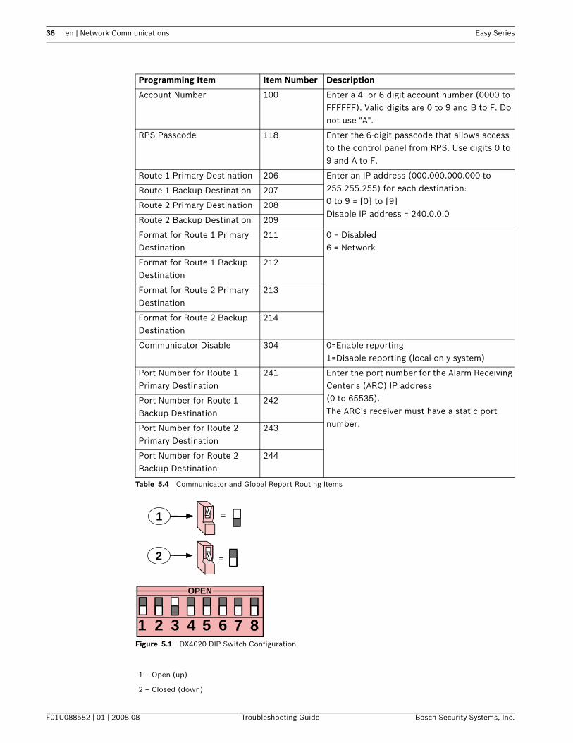
Solution:Use the following steps to configure the control panel and the communicator:1. Enter an account number in the control panel.
Refer to Table 5.4 on page 36.2. Enter an IP address for the CMS receiver in the desired routing destinations.
Refer to Table 5.4 on page 36.3. Configure the format for the routing destinations to 6 (Network).
Refer to Table 5.4 on page 36.4. Configure a port number for the routing destinations.
Refer to Table 5.4 on page 36.5. Configure Communicator Disable to 0 (enable reporting).
Refer to Table 5.4 on page 36.6. Configure anti-replay in the control panel to match the receiver's configuration.7. If using an ITS-DX4020-G communicator, configure the ITS-DX4020-G using SMS or a USB
connection.8. If using a DX4020 communicator, configure the DX4020's DIP switches to Address 134.
Refer to Figure 5.1 on page 36.
5.1.28 When I use RPS to log into the control panel with a DX4020 IP connection, I get bus device trouble for Address 134 (DX4020 module supervision failure).
Cause:The DX4020 module requires a firmware upgrade.
Solution:Upgrade the DX4020 with ROM v2.23 or newer. Contact your Bosch representative and request the R21-DX40XX-ROM Update Kit (P/N: F.01U.073.023).

34 en | Network Communications Easy Series
F01U088582 | 01 | 2008.08 Troubleshooting Guide Bosch Security Systems, Inc.
5.1.29 The control panel does not communicate with RPS using the communicator module.
Causes:– The control panel, the communicator module, or both are not configured correctly.– If using the ITS-DX4020-G communicator, the network is not configured for wireless
unattended access.
Solution:Use the following steps to configure the control panel and the DX4020 for RPS communication:1. Configure the control panel for RPS communication.
Refer to Table 5.4 on page 36.2. If using an ITS-DX4020-G communicator, configure the ITS-DX4020-G using SMS or a USB
connection.If using the DX4020, configure the DX4020's DIP switches to Address 134.Refer to Figure 5.1 on page 36.
5.1.30 The communicator module does not power on (no LEDs are lit).
Cause:The power wiring or power supply has a problem.
Solution:Check the wiring between the communicator module and the control panel, as shown in the
Easy Series System Reference Guide.
Easy Series Network Communications | en 35
Bosch Security Systems, Inc. Troubleshooting Guide F01U088582 | 01 | 2008.08
5.2 Network Communications Frequently Asked Questions (FAQs)
Table 5.3 Network Communications FAQs
5.2.1 Alarm reporting is configured on Route 1 with both a primary and a backup destination. Generating an alarm tests only the primary route. How do I test communications to the backup destination?Refer to Table 5.4, page 36 while performing the following steps:1. Configure the Route 2 Primary Destination, Item 208, the same as the Route 1 Backup
Destination, Item 207.2. Configure the Format for Route 2 Primary Destination, Item 213, the same as the Format
for Route 1 Backup Destination, Item 212.3. Configure the Communication Test Manual, Item 362, as either 2, Route 2 only, or 3, both
Route 1 and Route 2.4. Perform a communicator test using either the One-Button Test or the telephone menu.
Section Number and FAQ Page Reference
Section 5.2.1 Alarm reporting is configured on Route 1 with both a primary and a backup destination. Generating an alarm tests only the primary route. How do I test communications to the backup destination?
page 35
iNOTICE! This tests that the control panel can communicate with the backup destination, but does not verify that the Route 1 backup destination is configured correctly.
36 en | Network Communications Easy Series
F01U088582 | 01 | 2008.08 Troubleshooting Guide Bosch Security Systems, Inc.
Table 5.4 Communicator and Global Report Routing Items
Figure 5.1 DX4020 DIP Switch Configuration
Programming Item Item Number Description
Account Number 100 Enter a 4- or 6-digit account number (0000 to FFFFFF). Valid digits are 0 to 9 and B to F. Do not use "A".
RPS Passcode 118 Enter the 6-digit passcode that allows access to the control panel from RPS. Use digits 0 to 9 and A to F.
Route 1 Primary Destination 206 Enter an IP address (000.000.000.000 to 255.255.255) for each destination:0 to 9 = [0] to [9]Disable IP address = 240.0.0.0
Route 1 Backup Destination 207
Route 2 Primary Destination 208
Route 2 Backup Destination 209
Format for Route 1 Primary Destination
211 0 = Disabled6 = Network
Format for Route 1 Backup Destination
212
Format for Route 2 Primary Destination
213
Format for Route 2 Backup Destination
214
Communicator Disable 304 0=Enable reporting1=Disable reporting (local-only system)
Port Number for Route 1 Primary Destination
241 Enter the port number for the Alarm Receiving Center's (ARC) IP address(0 to 65535).The ARC's receiver must have a static port number.
Port Number for Route 1 Backup Destination
242
Port Number for Route 2 Primary Destination
243
Port Number for Route 2 Backup Destination
244
1 – Open (up)
2 – Closed (down)
OPEN
1 2 3 4 5 6 7 8
1
2
=
=

Easy Series System Operation | en 37
Bosch Security Systems, Inc. Troubleshooting Guide F01U088582 | 01 | 2008.08
6 System Operation
6.1 System Operation Frequently Asked Questions (FAQs)
Table 6.1 System Operation FAQs
6.1.1 Will the system work if the voice module is different than the programmed country code?Yes. The voice module operates independently from the programmed country code.
Section Number and FAQ Page Reference
Section 6.1.1 Will the system work if the voice module is different than the programmed country code?
page 37
Section 6.1.2 How do I add a user or token or key fob? page 38
Section 6.1.3 My token does not work when I present it to the control center. How do I fix this?
page 38
Section 6.1.4 How do I delete a user? page 38
Section 6.1.5 I assigned a token to User 1 (Master User). Can I delete this token?
page 39
Section 6.1.6 How do I replace a user's lost token or key fob? page 39
Section 6.1.7 How do I reset a fire point? page 39
Section 6.1.8 How do I configure a four-wire smoke detector? page 39
Section 6.1.9 Can I reset an emergency alarm? page 39
Section 6.1.10 Can I turn the system on if there is a malfunction, such as a loss of main power?
page 39
Section 6.1.11 Why do I hear the siren beep during Entry Delay? page 40
Section 6.1.12 Why does the siren activate during a Panic alarm? page 40
Section 6.1.13 My history log and central station report show Point 0 and User 0. What are these?
page 40
Section 6.1.14 The users are complaining that the control center isn’t reading the tokens at all, or it only reads a token if the token is pressed against the control center. Is there anything that will increase the control center’s sensitivity to tokens?
page 40
Section 6.1.15 I hear a grumbling noise in the programming telephone. What is causing the noise?
page 40
Section 6.1.16 How do I perform a Direct Connect between RPS and the control panel?
page 40
Section 6.1.17 What does it mean when the human symbol on the control center jumps back into the circle while arming the zone as unoccupied?
page 40
Section 6.1.18 Why doesn’t the system arm when there is an open point and I try to arm using my token?
page 41
Section 6.1.19 Why doesn’t the voice transmission work correctly? page 41
Section 6.1.20 Why doesn’t the phone menu provide the Discovery Mode option?
page 41
Section 6.1.21 Why can’t I configure Custom arming? page 41

38 en | System Operation Easy Series
F01U088582 | 01 | 2008.08 Troubleshooting Guide Bosch Security Systems, Inc.
6.1.2 How do I add a user or token or key fob?Only the master user can add a user or token or key fob.From the control center:
Entering the User Menu1. Press and hold [3].2. When prompted, present the master user token or enter the master user passcode.
Adding a User1. Press [1] to add a new user.2. Enter a passcode. Re-enter the new passcode when asked.
The system announces that the passcode was added.3. Press [1] to add a token to the new user.4. Present the token to the control center when asked.
The system announces that the token was added.5. Press [2] to record a user description (optional).6. Press [4] to add a key fob (optional).7. Repeat the steps in Section Adding a User, page 38, or press [5] to exit.From a phone:1. Start a phone session.2. When prompted, enter the master user passcode.3. Press [4] to select the User Menu.4. Repeat the steps in Section Adding a User, page 38, or press [#] to exit.If you are the master user and you cannot enter the User Menu when you present your token, you must assign your token as the master user token. Use the master user passcode to enter
the User Menu, and then assign a token to yourself.
6.1.3 My token does not work when I present it to the control center. How do I fix this?Your token is not assigned to you. If you are not the master user, see the master user.If you are the master user, refer to the previous question for instructions on adding a token to a user.
6.1.4 How do I delete a user?Only the master user can delete a user.From the control center:
Entering the User Menu1. Press and hold [3].2. When prompted, present the master user token or enter the master user passcode.3. Press [3] to delete a user.4. When prompted, present the master user token or enter the master user passcode.

Easy Series System Operation | en 39
Bosch Security Systems, Inc. Troubleshooting Guide F01U088582 | 01 | 2008.08
Deleting a User1. Press [3] to delete a user.2. To select the first available user (not the master user), press [1]. To select a different
user, press [2].Repeat this step until you select the desired user.
3. Press [1] to delete the user.The system announces that the user was deleted.The voice description is not deleted. Record a new description for a user that replaces the deleted user.
4. Repeat Section Deleting a User, page 39 to delete more users, tokens, and key fobs, or press [5] to exit.
From a phone:1. Start a phone session.2. When prompted, enter the master user passcode.3. Press [4] to select the User Menu.4. Repeat the steps in Section Deleting a User, page 39 to delete users and tokens, or press
[#] to exit.To delete only a token:1. Delete the user (follow either the control center or phone procedure above).2. Add the user, but skip the step to assign a token or key fob.
Follow either the control center or phone procedure described in Section 6.1.2 How do I add a user or token or key fob?, page 38.
6.1.5 I assigned a token to User 1 (Master User). Can I delete this token?No. Once a token is assigned to User 1, User 1 always requires a token. If User 1 loses a token, replace the user’s token.
6.1.6 How do I replace a user's lost token or key fob?1. Save the user's passcode (record it elsewhere).2. Access the User Menu from either the control center or the User Phone Menu.3. Delete the user.4. Re-enter the user (use saved passcode).5. Add the new token or key fob.
6.1.7 How do I reset a fire point?1. To silence the alarm, present your token to the control center, or enter your passcode.2. Repeat Step 1 to reset the fire point.
This procedure applies to any fire point type, such as a smoke detector, heat detector, or pull station.
6.1.8 How do I configure a four-wire smoke detector?Connect the smoke detector's power wires to any programmable output. Then select "System Reset" for the output's function.
6.1.9 Can I reset an emergency alarm?No. When an emergency alarm starts (press and hold both [1] and [2] keys on control center), the system announces an emergency alarm message once every minute for five minutes.
6.1.10 Can I turn the system on if there is a malfunction, such as a loss of main power?Yes. Present your token twice to the control center.

40 en | System Operation Easy Series
F01U088582 | 01 | 2008.08 Troubleshooting Guide Bosch Security Systems, Inc.
6.1.11 Why do I hear the siren beep during Entry Delay?Graduated Annunciation (Expert Programming Item Number 148) is enabled. If this item is enabled, the outputs periodically activate during Entry Delay to remind you to turn your system off.
6.1.12 Why does the siren activate during a Panic alarm?Panic alarm is programmed for audible alarm.In expert programming, change Expert Programming Item Number 890 from 1 (audible alarm) to 2 (silent alarm).
6.1.13 My history log and central station report show Point 0 and User 0. What are these?Point 0 = on-board input for EZTS tamper switch.User 0 = installer.
6.1.14 The users are complaining that the control center isn’t reading the tokens at all, or it only reads a token if the token is pressed against the control center. Is there anything that will increase the control center’s sensitivity to tokens?This symptom occurs when:– The control panel does not have a good earth ground.– If you have more than one control center, they might be mounted too close to each other.
Ensure that there is at least 1.2 m (4 ft) between each control center.– The control center is installed too close to metal objects.– The control center is installed too close to a high-power cable.– The control center is installed too close to light dimmer that emits RF noise.To correct the problem:
– Ensure that you do not run two or more sets of control center wiring together. Also,
ensure that you do not coil extra control center wiring inside of the control panel's enclosure. The maximum control center cable length is 3 m (10 ft).
– If you have more than one token on a key chain, separate the tokens. Tokens that are too close to one another interfere with control center operation.
– Ensure that the control center is not installed too close to a light dimmer.
– Make sure the tokens are enrolled into the system.
6.1.15 I hear a grumbling noise in the programming telephone. What is causing the noise?This symptom occurs when the system does not have a good earth ground. Ensure that the control center has a good earth ground.
6.1.16 How do I perform a Direct Connect between RPS and the control panel?Press the Test button on the control panel before clicking Connect in RPS. You might also need to install a 300 Ω resistor in series with TIP or RING.
6.1.17 What does it mean when the human symbol on the control center jumps back into the circle while arming the zone as unoccupied?The system expects that one point in the zone (usually an entry/exit door) gets activated to ensure that the person has left the building. If this is not the desired system behavior, set feature 132 (Auto Protection Level) to 0.

Easy Series System Operation | en 41
Bosch Security Systems, Inc. Troubleshooting Guide F01U088582 | 01 | 2008.08
6.1.18 Why doesn’t the system arm when there is an open point and I try to arm using my token?Set feature 153 (Key Fob Arming) to 2 or 3.
6.1.19 Why doesn’t the voice transmission work correctly?The control panel makes a configurable number of attempts to destination one and two together. Confirm that features 204 (Voice Format Message Delivery Attempts) and 305 (Route Attempts) are configured as desired.
6.1.20 Why doesn’t the phone menu provide the Discovery Mode option?If it is an existing system with programmed wireless devices, then select Add wireless devices from the menu.If it is a new system, then erase everything from the system and discover all factory defaulted devices in the environment.
6.1.21 Why can’t I configure Custom arming?Custom arming is only available after you have activated the feature for at least one zone.

42 en | Control Center Easy Series
F01U088582 | 01 | 2008.08 Troubleshooting Guide Bosch Security Systems, Inc.
7 Control Center
7.1 Control Center Frequently Asked Questions (FAQs)
Table 7.1 Control Center FAQs
7.1.1 How do I set the control center's address?On the control center's printed circuit board, turn the rotary switch to the desired position (1 to 4). Each control center must have a unique address.
7.1.2 Why doesn't the control center initialize? All I see is a flashing amber circle.Ensure that the rotary address switch on the control center's printed circuit board is properly set and not halfway between two numbers. Also, ensure that each control center has a unique address from 1 to 4.
7.1.3 The control center beeps when I present a token, but nothing else happens. What's wrong?Your token is unassigned. If you are the master user, enter the master user passcode, select the User Menu, and assign a token to yourself. For all other users with this problem, the master user must enter the User Menu and assign a token to the appropriate user(s).
7.1.4 Why is the control center making a buzzing noise?Make sure the analog audio cable is twisted pair.
Section Number and FAQ Page Reference
Section 7.1.1 How do I set the control center's address? page 42
Section 7.1.2 Why doesn't the control center initialize? All I see is a flashing amber circle.
page 42
Section 7.1.3 The control center beeps when I present a token, but nothing else happens. What's wrong?
page 42
Section 7.1.5 What do the control center LEDs indicate during system startup?
page 43
Section 7.1.6 The control center shows a broken green circle, even though all points are normal. What does this mean?
page 43
Section 7.1.7 The users are complaining that the control center isn’t reading the tokens at all, or it only reads a token if the token is pressed against the control center. Is there anything that will increase the control center’s sensitivity to tokens?
page 43
Section 7.1.8 What should I do if the control center isn’t functional? page 43
Section 7.1.9 What should I do if the control center does not “speak”? page 43
Section 7.1.4 Why is the control center making a buzzing noise? page 42

Easy Series Control Center | en 43
Bosch Security Systems, Inc. Troubleshooting Guide F01U088582 | 01 | 2008.08
7.1.5 What do the control center LEDs indicate during system startup?Refer to Table 7.2.
Table 7.2 Control Center LEDs During System Startup
7.1.6 The control center shows a broken green circle, even though all points are normal. What does this mean?During the initial point walk test, a wLSN device was not tested.Enter the point walk test again, and make sure that all points are tested so that the system announces that “Point ## was tested” for every point.
7.1.7 The users are complaining that the control center isn’t reading the tokens at all, or it only reads a token if the token is pressed against the control center. Is there anything that will increase the control center’s sensitivity to tokens?This symptom occurs when:– The control panel does not have a good earth ground.– If you have more than one control center, they might be mounted too close to each other.
Ensure that there is at least 1.2 m (4 ft) between each control center.– The control center is installed too close to metal objects.– The control center is installed too close to a high-power cable.– Ensure that you do not run two or more sets of control center wiring together. Also,
ensure that you do not coil extra control center wiring inside of the control panel's enclosure. The maximum control center cable length is 3 m (10 ft).
– If you have more than one token on a key chain, separate the tokens. Tokens that are too close to one another interfere with control center operation.
– Make sure the tokens are enrolled into the system.
7.1.8 What should I do if the control center isn’t functional?– If the control center LEDs do not light at all, check the power wiring between the control
center and the control panel.– If the circle LEDs are flashing, then there is no bus traffic. If the problem continues, check
the data wiring between the control center and the control panel.– If the circle LEDs are spinning, then check the control center’s address.
7.1.9 What should I do if the control center does not “speak”?– Confirm that the voice module is inserted into the control panel completely.– Check the analog audio wiring between the control center and the control panel.
Stage Time Interval Control Center Indicators
1 0 – 15 sec. Intermittent flashing green icon. Indicates the control center's firmware version. Should be one flash, followed by three flashes.
2 15 – 45 sec. Flashing amber circle. System is powering up, and there is no bus activity.
3 45 – 75 sec. Single rotating amber segment. System is powering up, and there is bus activity.
iNOTICE! If the control panel is busy speaking using the telephone connection, it cannot also speak using the control center.

44 en | Passcodes Easy Series
F01U088582 | 01 | 2008.08 Troubleshooting Guide Bosch Security Systems, Inc.
8 Passcodes
8.1 Passcodes Frequently Asked Questions (FAQs)
Table 8.1 Passcodes FAQs
8.1.1 What are the default installer and master user passcodes?– Default installer passcode: 5432 when passcode length = four digits; 543211 when
passcode length = six digits– Default master passcode: 1234 when passcode length = four digits; 123455 when
passcode length = six digits
8.1.2 Why can't I enter the Installer Menu using the installer passcode?Expert Programming Item Number 142, Restrict Installer Passcode, is enabled. The master user must first present his token or enter his passcode, before you enter the installer passcode. The Installer Passcode is enabled until a user turns the system on.
Section Number and FAQ Page Reference
Section 8.1.1 What are the default installer and master user passcodes? page 44
Section 8.1.2 Why can't I enter the Installer Menu using the installer passcode?
page 44

Easy Series Error Messages | en 45
Bosch Security Systems, Inc. Troubleshooting Guide F01U088582 | 01 | 2008.08
9 Error MessagesThe messages listed in Table 9.1 are sorted alphabetically by error message text.
Error Messages Description Solution
AC problem. System AC fault. – Check the main AC power source.– Check the wiring between the power supply and
the control panel.
AC problem, output 5/6/7/8.
AC failure on the identified output.
Check the power wiring to the identified output.
AC problem, "recorded description".
AC failure on point 1 through 32, as identified in the recorded description.
Check the power wiring to the identified point.
Battery is low. The system battery is low. – If an extended loss of main AC power occurred, allow time for the system to recharge the system battery.
– Replace the system battery.
Battery is missing. The system battery is missing. – If an extended loss of main AC power occurred, allow time for the system time to recharge the system battery.
– Check the wiring between the system battery and the control panel.
Bus device missing 50. The wLSN Hub is missing. Check the data wiring between the wLSN Hub and the control panel.
Bus device missing 102/103/104.
The DX2010 at the identified address is missing.
– Check the data wiring between the identified DX2010 and the control panel.
– If a point is enabled without a wireless ID, the control panel assumes it is an expander point. Disable the point. If the point is wireless, go through the discovery process.
Bus device missing 134. The network interface module (for example, the DX4020) is missing.
Check the data wiring between the network interface module and the control panel.
Bus device tamper 50. The wLSN Hub is tampered. Clear the wLSN Hub tamper condition.
Bus device tamper 102/103/104.
The DX2010 at the identified address is tampered.
Clear the tamper condition on the identified DX2010.
Bus device trouble 50. The wLSN Hub is in trouble condition.
Ensure that the wLSN Hub's address matches the Hub address programmed into the control panel.
Bus device trouble 102/103/104.
The DX2010 at the identified address is in an overcurrent condition.
Reduce the current draw on the identified DX2010.
Communication problem 1.
The control panel cannot send an event to the Central Monitoring Station.
Check your network interface module, GPRS communicator, and everything else between the system and the Central Monitoring Station.
Control center missing1/2/3/4.
The identified control center is missing.
Check the data wiring between the identified control center and the control panel.

46 en | Error Messages Easy Series
F01U088582 | 01 | 2008.08 Troubleshooting Guide Bosch Security Systems, Inc.
Control center problem1/2/3/4.
The identified control center has a problem with its audio connection.
Check the audio wiring between the control center and the control panel.
Control center tamper 1/2/3/4.
The identified control center is tampered.
Check the cover on the identified control center.
Hardware test 1 failed. Configuration data checksum error.
Change any configuration item in the control panel, wait 2 min, then power cycle the control panel.
Hardware test 2 failed. RAM memory fault. Replace the control panel.
Hardware test 3 failed. Flash memory checksum fault. Replace the control panel.
Hardware test 4 failed. Stack fault. Replace the control panel.
Low battery, "recorded user name".
The key fob used by person identified in the recorded message has a low battery.
Replace the battery in the identified user's key fob.
Missing output 5/6/7/8. The identified output is missing. Refer to Section 1.1.1 wLSN devices are missing. Control center does not announce "Bus device missing 50" or "Bus device trouble 50"., page 7.
Missing "recorded description".
Point 1 through 32, as identified in the recorded description, is missing.
Refer to Section 1.1.1 wLSN devices are missing. Control center does not announce "Bus device missing 50" or "Bus device trouble 50"., page 7.
Network failed 1/2/3/4. The identified IP path failed. Check your network interface module, GPRS communicator, and everything else between the system and the Central Monitoring Station.
Phone line problem. There is a problem with the telephone connection.
– Check the telephone line connections to the control panel.
– Check the telephone line functioning with a butt set or known-good telephone.
Tamper 0. The control panel's enclosure is tampered.
Check the control panel enclosure's door, tamper switch, and tamper switch wiring.
Tamper output 5/6/7/8. The identified output is tampered.
Check the cover on the identified output.
Tamper "recorded description".
Point 1 through 32, as identified in the recorded message, is tampered.
– Check the cover on the identified point.– Check the wiring to the device's input.
Trouble output 5/6/7/8. The wireless device informed the system that it is in trouble condition.
Replace the wireless device.
Trouble "recorded description".
Point 1 through 32, as identified in the recorded message, is in trouble condition.
– Replace the wireless point.– For smoke detectors, clean the smoke chamber.
Warning device problem. The wired supervised siren connected to the control panel is in trouble condition.
Check the wiring between the siren and the control panel.
Wireless low battery output 5/6/7/8.
The identified output has low batteries.
Replace the batteries in the identified output.
Error Messages Description Solution

Easy Series Error Messages | en 47
Bosch Security Systems, Inc. Troubleshooting Guide F01U088582 | 01 | 2008.08
Table 9.1 Error Messages
Wireless low battery "recorded description".
Point 1 through 32, as identified in the recorded message, has low batteries.
Replace the batteries in the identified point.
Wireless receiver jammed 50.
The wLSN Hub's receiver is jammed.
– Identify and eliminate the source of RF signals that is interfering with the wLSN Hub.
– Relocate the wLSN Hub.
Error Messages Description Solution

48 en | Error Messages Easy Series
F01U088582 | 01 | 2008.08 Troubleshooting Guide Bosch Security Systems, Inc.


Bosch Security Systems, Inc. www.boschsecurity.com © Bosch Security Systems, Inc., 2008