Embed Size (px)
Citation preview

INSTRUCTION MANUAL
F SERIES SPEAKER SYSTEM
F-160G/F-160W (Low impedance)F-160GM/F-160WM (High impedance)F-160WP (High impedance/outdoor use)F-240G/F-240W (Low impedance)F-240GM/F-240WM (High impedance)
TABLE OF CONTENTS
1. SAFETY PRECAUTIONS . . . . . . . . . . . . . . . . . . . . . . . . . . . . .
2. DIMENSIONAL DIAGRAM AND NOMENCLATURE . . . . . .
3. HANDLING PRECAUTIONS . . . . . . . . . . . . . . . . . . . . . . . . . .
4. FEATURES . . . . . . . . . . . . . . . . . . . . . . . . . . . . . . . . . . . . . . . . .
5. OVERLOAD PROTECTION CIRCUITRY INFORMATION
6. IMPEDANCE CHANGE . . . . . . . . . . . . . . . . . . . . . . . . . . . . . . .
7. REAR COVER USAGE . . . . . . . . . . . . . . . . . . . . . . . . . . . . . . .
8. LOGO BADGE REORIENTATION . . . . . . . . . . . . . . . . . . . . .
9. OUTDOOR USE (F-160WP ONLY) . . . . . . . . . . . . . . . . . . . .
10. SPECIFICATIONS . . . . . . . . . . . . . . . . . . . . . . . . . . . . . . . . . .
11. CHARACTERISTIC DIAGRAM . . . . . . . . . . . . . . . . . . . . . . .
Thank you for buying the TOA speaker system.Please read this manual carefully to get the best performance from this speaker.
TOA Corporation
2
3
4
4
4
5
5
6
6
7
8
1. SAFETY PRECAUTIONS
Safety Symbol and Message ConventionsSafety symbols and messages are used in this manual to prevent bodily injury and property damage whichcould result from mishandling. The conventions of the symbols and messages are described below. Beforedoing anything else, read this manual first so you are thoroughly aware of the potential safety hazards as wellas understand the safety symbols and messages. Then before operating your product, read through theinstruction manual so you are familiar with its general operation.
Symbols Symbols of caution actions Symbols of prohibited actions
WARNING Indicates a potentially hazardous situation which, if mishandled,could result in death or serious personal injury.
When Installing the Unit
Install the unit only in a location that can structurally support the weight of the unit and
the mounting bracket. Doing otherwise may result in the speaker falling down and
causing personal injury and/or property damage.
CAUTIONIndicates a potentially hazardous situation which, if mishandled,could result in moderate or minor personal injury, and/orproperty damage.
When the Unit is in Use
Do not stand or sit on a speaker as this may cause it to fall down or drop, resulting inpersonal injury and/or property damage.
Do not operate the speaker for an extended period of time with the sound distorting.This is an indication of a malfunction, which in turn can cause heat to generate and
result in a fire.
Be sure to read the instructions in this section carefully before use.Make sure to observe the instructions in this manual as the conventions of safety symbols and messagesregarded as very important precautions are included.We also recommend you keep this instruction manual handy for future reference.
CAUTION PROHIBITION
CAUTION
PROHIBITION
2
PROHIBITION

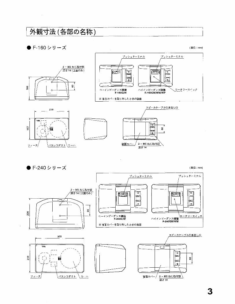
2. DIMENSIONAL DIAGRAM AND NOMENCLATURE
F-160 Series (Unit: mm)
M5 screw mounting hole x 2Depth: 14 (Top panel only)
Push terminal Push terminal
Rotary switchHigh-impedance modelsF-160GM/F-160WM/F-160WP
Low-impedance modelsF-160G/F-160W
[Rear panel without a rear cover]
Cable feed slot
Rear cover M5 screw mounting hole x 2Depth: 14
(Unit mm)
Tweeter Bass-reflex duct Woofer
F-240 Series
Push terminal
Low-impedance modelsF-240G/F-240W
[Rear panel without a rear cover]
High-impedance modelsF-240GM/F-240WM
Rotary switch
Push terminal
Cable feed slot
Tweeter Bass-reflex duct Woofer Rear cover M5 screw mounting hole x 2Depth: 14
M5 screw mounting hole x 2Depth: 14 (Top panel only)
3

3. HANDLING PRECAUTIONS
4. FEATURES
5. OVERLOAD PROTECTION CIRCUITRY INFORMATION
(LOW-IMPEDANCE MODELS ONLY)
4
The F-160G, F-160W, F-240G, and F-240W have a built-in overload protection circuitry.
If the excessive input is applied to a woofer or tweeter, the overload protection circuitry is activated and cutsoff the signal supply to the speaker component.A sudden drop of the volume level of either the high or low frequencies during speaker operation indicatesthat the overload protection circuitry has been activated. In such a case, reduce the amplifier volume and justwait. The protection circuitry is automatically reset after approximately 3-30 seconds. After the circuitry isreset, set the volume at a lower level than before.
[Important Note]This overload protection circuitry does not perfectly protect the speaker component. Depending upon the
excessive input to be applied, the protection circuitry may not operate, causing damage to the speakercomponent. In addition, the circuitry may not be restored to the previous state if the excessive input is applied
continuously for long time. Take special care that the excessive input is not applied to the speaker during use.
Two-way bass-reflex system.High efficiency, wide range, and high input power handling capacity.F-160 series: High power capacity 13 cm woofer with a large 90 mm magnetic circuit, and high-efficiency3 cm dome tweeter with a large 70 mm magnetic circuit.F-240 series: High power capacity 16 cm woofer with a large 90 mm magnetic circuit, and high efficiency
3 cm dome tweeter with a large 70 mm magnetic circuit and a titanium diaphragm.The tweeter employs a constant directivity horn which ensures uniform sound dispersion of 90 ° horizontaland 90° vertical.
Independent built-in overload protection circuitry for woofer and tweeter. (Low-impedance models only)A detachable rear cover cleanly conceals the speaker terminals.
Acoustically efficient polypropylene enclosure.Optional wall and ceiling mounting brackets.F-160WP: Drip-proof construction makes the speaker system ideal for outdoor use.
Use optional mounting brackets when mounting the speaker to the ceiling or wall.Avoid using the speaker on the beach because the speaker's life can be greatly shortened by sea breezes.TOA takes no responsibility for any accident or equipment failure due to inadequate installation places orincorrect installation methods or disassembly or modifications carried out for the purposes other than repair
service.The F series speaker is not magnetically shielded. Install it as far away as possible from color televisions or
video monitors to avoid degradation in television picture quality.

6. IMPEDANCE CHANGE (HIGH-IMPEDANCE MODELS ONLY)
Because the following models have a built-in matching transformer, connect them to the amplifier with ahigh-impedance (70 or 100) line output.
F-160GM, F-160WM, F-160WP, F-240GM and F-240WM
Input impedance can be switched in five steps, asshown in the table at right (factory-preset to 330ohms). To change, set the rotary switch to thedesired impedance using a screwdriver blade.
[Note]When using the 100 line, never set the impedance to
170 ohms. The speaker itself or the power amplifier
may be damaged.
7. REAR COVER USAGE
F Series speakers feature a rear cover that cleanly
conceals the speaker terminals on the rear panel.
To remove the cover, insert a finger in the line feedslot and pull the cover away from the speaker. Toreattach, simply snap the cover back into place.
If required, the positioning of the cover's line feedslot can be easily reversed by snapping the cover on"upside down".
Model F-160WP must be mounted with the line feed
slot facing down.
Cable feed slot
Rear cover
F Series speaker
Speaker cable
Rear cover
Upward speaker cable routing(Line feed slot faces up.)
Downward speaker cable routing(Line feed slot faces down.)
5
Rotary switch 2 k
1 k
500
330
NC
170
5 W
10 W
20 W
30 W
2.5 W
5 W
10 W
15 W
30 W

8. LOGO BADGE REORIENTATION
The speaker's front grille logo badge is attached withdouble-sided tape. To change its orientation, carefully peel thelogo off the grille and stick it back on again in the same location
in the desired orientation.
9. OUTDOOR USE (F-160WP ONLY)
Speaker grille
Logo badge
Rear cover
Speaker cable
The inside of the rear cover
Cable guide
When mounting on the wall
Horizontal 0°
Install within this range.
When mounting under the eaves
Downward 15
Downward 60 °
Cannot be positioned vertically.
Model F-160WP features drip-proof construction. However, do not dash water over it when cleaning as thismay cause damage to the speaker components.
When installing the F-160WP outdoors in a snowy area, protect the speaker by preventing snow from pilingup on it.
Model F-160WP can be permanently installed outdoors, andother F Series speakers cannot.
In the F-160WP, the rear cover prevents water from gettinginto the terminal section. When installing the F-160WPoutdoors, make sure that the rear cover is mounted with the
line feed slot facing down.
If using a thicker speaker cable that does not easily fit through
the rear cover's cable guide, use a knife to cut out the rubber
cable guide along the imprinted groove, as shown in the
illustration at right.
[Note]When mounting model F-160WP on the wall or under theeaves, be sure to use optional outdoor mounting brackets.Adjust the speaker installation angle and direction within the
ranges shown in the figures below:
Downward 45 Mounting bracket Install within this range.
6
Mounting bracket

10. SPECIFICATIONS
Model No.
Enclosure Type
SpeakerLow frequencyHigh frequency
Rated ImpedancePower Handling Capacity
Output Sound Pressure LevelCrossover FrequencyFrequency Response
Input ConnectorEnclosure MaterialColorDimensionsWeight
F-160G F-160W F-240GBass-reflex type
13 cm cone speaker3 cm dome speaker (film diaphragm)
F-240W
16 cm cone speaker3 cm dome speaker (titanium diaphragm)
8
Continuous pink noise: 50W (*)Continuous program: 150W
91 dB (1 W/1 m)(**) 92 dB (1 W/1 m) (**)4 kHz (passive network)
100 - 20,000 Hz ( -10 dB)150 - 13,000 Hz ( -3 dB)
Dark gray
65 - 20,000 Hz ( -10 dB)130 - 15,000 Hz ( -3 dB)
Push terminalPolypropylene resin
White250 (W) x 157 (H) x 169 (D) mm
Approximately 3.3 kg
Model No.Enclosure Type
SpeakerLow frequencyHigh frequency
Rated Impedance
Rated Input PowerOutput Sound Pressure LevelCrossover FrequencyFrequency Response
Input ConnectorEnclosure MaterialColorDimensionsWeight
F-160GM
Dark gray White355 (W) x 210 (H) x 226 (D) mm
Approximately 4.9 kg
F-160WM F-240GMBass-reflex type
13 cm cone speaker3 cm dome speaker (film diaphragm)
F-240WM
16 cm cone speaker3 cm dome speaker (titanium diaphragm)
100 Line: 330 (30 W), 500 (20 W), 1 k (10 W), 2 k (5 W)70 Line:170 (30 W), 330 (15 W), 500 (10 W),1 k (5 W), 2 k (2.5 W)
30 W91 dB (1 W/1 m)(**) 92 dB (1 W/1 m) (**)
4 kHz (passive network)100 - 20,000 Hz ( -10 dB)150 - 13,000 Hz ( -3 dB)
Dark gray
65 - 20,000 Hz ( -10 dB)130 - 15,000 Hz ( -3 dB)
Push terminalPolypropylene resin
White250 (W) x 157 (H) x 169 (D) mm
Approximately 3.9 kg
Dark gray White355 (W) x 210 (H) x 226 (D) mm
Approximately 5.5 kg
Model No.Enclosure Type
SpeakerLow frequencyHigh frequency
Rated Impedance
Rated Input PowerOutput Sound Pressure LevelCrossover FrequencyFrequency Response
Input ConnectorEnclosure MaterialColorDimensionsWeight
F-160WPBass-reflex type
13 cm cone speaker (drip-proof)3 cm dome speaker (film diaphragm)100 Line : 330 (30 W), 500 (20 W), 1 k (10 W), 2 k (5 W)
70 Line : 170 (30 W), 330 (15 W), 500 (10 W), 1 k (5 W), 2 k (2.5 W)
30 W
91 dB (1 W/1 m)(**)4 kHz (passive network)100 - 20,000 Hz ( -10 dB)150 - 13,000 Hz ( -3 dB)
Push terminalPolypropylene resinDark gray250 (W) x 157 (H) x 169 (D) mmApproximately 3.9 kg
(*) Continuous 24 hours pink noise of 50 Hz - 20 kHz(**) Pink noise of 330 Hz - 3.3 kHz
Specifications are subject to change without notice.
7

11. CHARACTERISTIC DIAGRAM
F-160 Series Frequency Response (1 W/1 m)
F-160 Series Directional CharacteristicsVertical Horizontal
1000 Hz
2000 Hz
4000 Hz
8000 Hz10 dB/Div.
F-240 Series Frequency Response (1 W/1 m)
F-240 Series Directional CharacteristicsVertical Horizontal
1000 Hz
2000 Hz
4000 Hz
8000 Hz10 dB/Div.
TOA Corporation8
The manual in English is provided at the back.
F-160G, F-160WF-160GM, F-160WMF-160WPF-240G, F-240WF-240GM, F-240WM
533-06-005-80

2
3

4

5

6

7

8


![ML 160W E27 220-230V SG 1CT/24 - ML | PHILIPS · ML ML 160W E27 220-230V SG 1CT/24 Mixed Light lamps Product data General Information Cap base E27 [ E27] Burning Position VBU/VBD30](https://img.dokumen.tips/doc/110x75/5fc775ab12d4d65b575cb025/ml-160w-e27-220-230v-sg-1ct24-ml-philips-ml-ml-160w-e27-220-230v-sg-1ct24.jpg)