Embed Size (px)
Citation preview

1
FFIIEELLDD SSEERRVVIICCEE MMAANNUUAALL
MMPPUU66 BBAASSEE
IISSSSUUEE 22..22
2
FILE MODIFICATION HISTORY 30/06/08 First Revision – MPU6 Base V1.0 01/10/08 Video Top Box fitting Instructions added V1.1 16/01/09 Updated Safety Instructions V1.2 09/03/09 Updated Screens within Operator Config V1.3 08/04/09 Updated Alarm codes and Infill fitting instructions V1.4 26/02/10 Infill and Top Box PSU fitting instructions V1.5 09/04/10 Additional information added for infill cables V1.6 27/07/10 SR3e encryption installation instructions added V1.7 09/06/11 Coin and note mech additional screens added V1.8 09/06/11 JCM Vega Note acceptor maintenance added V1.8 27/07/11 Machine layout shots amended V1.9 19/08/11 Amendment to Coin mech encryption set up V2.0 07/11/11 NV11 note acceptor set up instructions added V2.1 21/11/11 Safety Notes Updated V2.1 10/01/12 New Barcrest logo added V2.2

3
Contents
Section A OPERATIONAL INFORMATION
1. SAFETY NOTICES ........................................................................................................... 6
1.1 ELECTRICAL SAFETY .................................................................................................... 7 1.2 CHEMICAL SAFETY ........................................................................................................ 7
1.3 FIRE SAFETY ................................................................................................................... 8 1.4 COMPONENT DISPOSAL ................................................................................................ 8 2. INTRODUCTION ............................................................................................................... 9 3. SETUP PROCEDURE .................................................................................................... 12 3.1 INSPECTION .................................................................................................................. 12
3.2 FIELD INSTALLATION ................................................................................................... 12 3.3 TOP BOX INSTALLATION ............................................................................................. 14 3.4 INFILL PANEL INSTALLATION ..................................................................................... 17 3.5 TOP BOX AND INFILL POWER SUPPLY FITTING INSTRUCTIONS ........................... 19
4. I BUTTON “DALLAS” KEYS ......................................................................................... 21 5. INITIAL POWER UP ....................................................................................................... 22
5.1 MAIN MENU ................................................................................................................... 22 5.2 EVENT LOGS ................................................................................................................. 23
5.3 SYSTEM INFORMATION ............................................................................................... 25 5.4 SOFTWARE VERIFICATION ......................................................................................... 25
5.5 GAME LICENSING ......................................................................................................... 26 5.6 ACCOUNTANCY ............................................................................................................ 29 5.7 CUSTOMER COLLECTIONS ......................................................................................... 30
5.8 CUSTOMER REFILL ...................................................................................................... 32 5.9 DEMO MODE .................................................................................................................. 32 5.10 UPDATES ....................................................................................................................... 33
5.11 CONFIGURATION .......................................................................................................... 34
5.12 GAME CONFIGURATION .............................................................................................. 34
5.13 THEME CONFIGURATION ............................................................................................ 37 5.14 TERMINAL CONFIGURATION....................................................................................... 39
5.15 SERVICE ........................................................................................................................ 45
4
SECTION B MAINTENANCE INFORMATION
1. INTRODUCTION ............................................................................................................. 54 2. MPU 6 SYSTEM.............................................................................................................. 54
2.1 MPU6 FAULT CODES .................................................................................................... 57 3. PC INFORMATION ......................................................................................................... 61 4. POWER SUPPLY INFORMATION ................................................................................. 63 5. MONITOR INFORMATION ............................................................................................. 64 5.1 TOUCH SCREEN CALIBRATION .................................................................................. 66
6. ENCRYPTED COIN MECHANISM REMOVAL AND SET UP INFORMATION ............. 67
6.1 INTRODUCTION ............................................................................................................. 67
6.2 COIN MECH REMOVAL ................................................................................................. 68 6.3 SR3e ENCRYPTION KEY RESET .................................................................................. 68 6.4 REPLACEMENT ENCRYPTED COIN MECH SET UP ................................................... 69 6.5 SERIAL DEVICES SET UP ............................................................................................ 69 7 NOTE ACCEPTOR INFORMATION ............................................................................... 71
7.1 NV11 NOTE ACCEPTOR MAINTANANCE .................................................................... 75 7.1.1 NV11 NOTE ACCEPTOR REMOVAL ............................................................................ 76
7.1.2 NV11 NOTE FLOAT JAM REMOVAL. ........................................................................... 76 7.1.3 MANUAL NOTE REMOVAL ........................................................................................... 76
7.1.4 NV11 BNV RESET PROCEDURE .................................................................................. 77
7.2 JCM VEGA NOTE ACCEPTOR MAINTANANCE .......................................................... 78
8. PAYOUT ASSEMBLY .................................................................................................... 81 9. L.E.D BOARD REPLACEMENT ..................................................................................... 84
10. BUTTON REPLACEMENT ............................................................................................. 86 11. TICKET PRINTER ........................................................................................................... 89 12. ADDITIONAL SECURITY ............................................................................................... 92

5
Section C TRIPLE 7’s PARTS LIST
SWITCH MODE PSU ................................................................................................................. 96 19” BOTTOM MONITOR WITH TOUCH SCREEN ................................................................... 96 19” TOP MONITOR ................................................................................................................... 96 MK6 INDUSTRIAL PC ............................................................................................................... 96 ARDAC ELITE NOTE ACCEPTOR ........................................................................................... 96 SR3e ENCRYPTED COIN MECH ............................................................................................. 96 HOPPER ASSEMBLY (No Hoppers) ....................................................................................... 96 10P COMPACT HOPPER ......................................................................................................... 96 SERIAL UNIVERSAL HOPPER ................................................................................................ 96 TRI-COLOUR LED PCB ............................................................................................................ 96 LED 6 DRIVER PCB .................................................................................................................. 96 MPU6 ........................................................................................................................................ 96 START “DISCO” BUTTON ....................................................................................................... 96 COLLECT BUTTON .................................................................................................................. 96 HELP BUTTON ......................................................................................................................... 96 TRANSFER BUTTON................................................................................................................ 96 FUTURE LOGIC TICKET PRINTER GEN 2 .............................................................................. 96 SECURITY STRAP KIT ............................................................................................................. 96 TOP BOX AND INFILL POWER SUPPLY ................................................................................ 96 NV11 NOTE FLOAT ACCEPTOR ............................................................................................. 96

6
Section A
OPERATIONAL INFORMATION
1. SAFETY NOTICES The following safety instructions apply to all game operators and service personnel. Specific warnings and cautions will be found throughout this manual where they apply. We recommend that you read these pages before preparing your “Triple 7’s” cabinet for play.
CE
Tested for compliance with- 2006/95/EC – The LVD Directive.
2004/108/EC – The EMC Directive.

7
GENERAL Barcrest make use of a wide range of components in the manufacture of their product, which are in turn supplied by a large number of manufacturers. Due to its limitations, it is not practical for this manual to contain all the relevant safety data for these products. If required, the manufacturer’s data sheets can be supplied. All parts used in Barcrest products are used within their specification limits and in accordance with sound engineering practice.
1.1 ELECTRICAL SAFETY CAUTION RISK OF ELECTRIC SHOCK 230 Volts is present within the machine. Only suitably qualified personnel should carry out servicing of the machine. Disconnect from the mains supply before disconnecting, removing or touching any internal components. SAFE CONNECTION TO SUPPLY To ensure the safe operation of this machine it must be connected to the mains supply using an approved power cord, which meets the requirements of IEC227. This cord must have an IEC approved connector at one end and an approved 13-amp plug fitted with a 5-amp fuse at the other. In the case of non-fused power cords, an approved and suitably rated Residual Current Device shall be used. INSULATION/EARTH BOND Insulation and earth bond electrical safety checks are made on all Barcrest machines before despatch. These tests should be then be undertaken annually, or whenever safety critical parts or connections are replaced. Insulation \ earth bond specifications for Barcrest machines are as follows: - Insulation > 9.9 Meg ohm @ 500V Earth Bond < 0.1 ohm @ 25 amps
1.2 CHEMICAL SAFETY Some component parts of Barcrest products contain small quantities of chemicals, which are to be considered hazardous should the components be accidentally damaged. These are: -
Electrolytic capacitors Semiconductors containing Beryllium Oxide and Gallium Arsenide Opto-electronic devices using Gallium Phosphide
Because of the corrosive or flammable nature of these chemicals, particular care is required in the case of spillage. Where these chemicals do come into contact with the skin or eyes, the affected area must be flushed with cold running water, and medical advice sought.
8
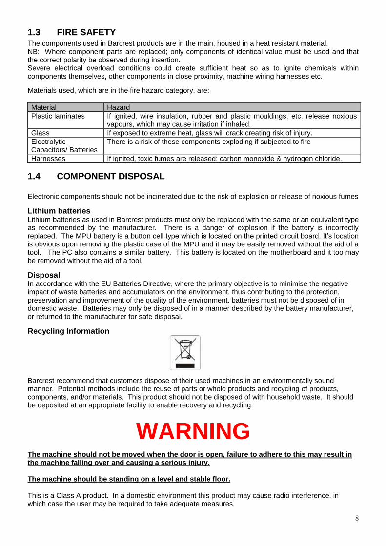
1.3 FIRE SAFETY The components used in Barcrest products are in the main, housed in a heat resistant material. NB: Where component parts are replaced; only components of identical value must be used and that the correct polarity be observed during insertion. Severe electrical overload conditions could create sufficient heat so as to ignite chemicals within components themselves, other components in close proximity, machine wiring harnesses etc.
Materials used, which are in the fire hazard category, are: Material Hazard Plastic laminates If ignited, wire insulation, rubber and plastic mouldings, etc. release noxious
vapours, which may cause irritation if inhaled. Glass If exposed to extreme heat, glass will crack creating risk of injury. Electrolytic Capacitors/ Batteries
There is a risk of these components exploding if subjected to fire
Harnesses If ignited, toxic fumes are released: carbon monoxide & hydrogen chloride.
1.4 COMPONENT DISPOSAL Electronic components should not be incinerated due to the risk of explosion or release of noxious fumes
Lithium batteries Lithium batteries as used in Barcrest products must only be replaced with the same or an equivalent type as recommended by the manufacturer. There is a danger of explosion if the battery is incorrectly replaced. The MPU battery is a button cell type which is located on the printed circuit board. It’s location is obvious upon removing the plastic case of the MPU and it may be easily removed without the aid of a tool. The PC also contains a similar battery. This battery is located on the motherboard and it too may be removed without the aid of a tool.
Disposal In accordance with the EU Batteries Directive, where the primary objective is to minimise the negative impact of waste batteries and accumulators on the environment, thus contributing to the protection, preservation and improvement of the quality of the environment, batteries must not be disposed of in domestic waste. Batteries may only be disposed of in a manner described by the battery manufacturer, or returned to the manufacturer for safe disposal.
Recycling Information
Barcrest recommend that customers dispose of their used machines in an environmentally sound manner. Potential methods include the reuse of parts or whole products and recycling of products, components, and/or materials. This product should not be disposed of with household waste. It should be deposited at an appropriate facility to enable recovery and recycling.
WARNING
The machine should not be moved when the door is open, failure to adhere to this may result in the machine falling over and causing a serious injury. The machine should be standing on a level and stable floor. This is a Class A product. In a domestic environment this product may cause radio interference, in which case the user may be required to take adequate measures.

9
2. INTRODUCTION
TRIPLE 7 MULTIGAME VIDEO PLATFORM With its stylish, distinctive looks and high earning potential, the Triple 7 Cabinet offers the ultimate in playability, functionality and security. Available as a standalone unit, or networked for server based gaming, Triple 7 is a multigame platform, which allows customers to refine and enhance their offer as Barcrest creates more great games. Every aspect of Triple 7 is designed for longevity. Built to the highest standards in a metal cabinet with hard chrome finish and long-life components, Triple 7 can be relied upon to look stunning and perform consistently for years to come.
7 WAYS TO ATTRACT THE PLAYER
Stunning Triple 7 stands out from the crowd Player-selectable multigame menu Interactive game screen High definition 19” LCD monitors Improved game presentation and flow Eye-catching top box and infill panels available Very fast game load speeds provide instant response
7 ADVANTAGES FOR THE OPERATOR
Separate and easily accessible note stacker/card reader/ticket printer Separate door opening with high security, multipoint locking system MPU5/6 as intelligent input/output interface Ardac Elite Note Acceptor to casino standards Card reader and ticket printer - TITO ready Universal/Compact hoppers High quality industrial PC with XP embedded operating system and Intel processor.
7 REASONS TO CHOOSE TRIPLE 7
Multigame format optimises earning potential Access to constant new stream of great games from Barcrest Proven, reliable Barcrest technology minimises downtime Pan European design with multi-language capability Compatibility with Server Based Gaming for ultimate functionality Serial Communication delivers improved security An exciting new era in gaming entertainment!
This manual is divided into three parts. The first part provides information necessary to install and operate the machine. The second part provides the service information necessary to understand how the Triple 7 cabinet and its components work and to be able to carry out repairs should a fault occur. The third part contains details of part numbers for the components used in the Triple 7’s cabinet. The information in the Setup Procedure should be followed to prepare the machine for installation in the field.

10
COIN ENTRY BEZEL
NOTE/TICKET ENTRY BEZEL
BELLY GLASS DOOR RELEASE LEVER
MAIN DOOR
OUTER CASH DOOR
CASH PAYOUT TRAY
GAME SPECIFIC BUTTONS
19” LCD TOUCHSCREEN MONITOR
19” LCD MONITOR
SPEAKER SPEAKER
TRIPLE 7’s MAIN EXTERNAL COMPONENTS VIEW
TICKET PRINTER BEZEL (WHEN FITTED)
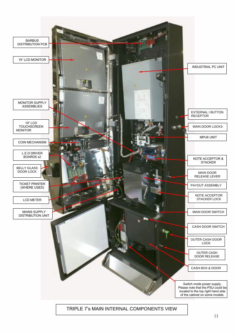
11
19” LCD MONITOR
19” LCD TOUCHSCREEN
MONITOR
Switch mode power supply. Please note that the PSU could be located to the top right hand side of the cabinet on some models.
COIN MECHANISM
L.E.D DRIVER BOARDS x2
LCD METER
MAINS SUPPLY DISTRIBUTION UNIT
TICKET PRINTER (WHERE USED)
INDUSTRIAL PC UNIT
MPU6 UNIT
NOTE ACCEPTOR & STACKER
PAYOUT ASSEMBLY
MAIN DOOR SWITCH
CASH DOOR SWITCH
NOTE ACCEPTOR STACKER LOCK
CASH BOX & DOOR
BARBUS DISTRIBUTION PCB
MAIN DOOR LOCKS
TRIPLE 7’s MAIN INTERNAL COMPONENTS VIEW
MONITOR SUPPLY ASSEMBLIES
EXTERNAL I BUTTON RECEPTOR
MAIN DOOR RELEASE LEVER
OUTER CASH DOOR LOCK
OUTER CASH DOOR RELEASE
LEVER
BELLY GLASS DOOR LOCK

12
3. SETUP PROCEDURE
3.1 INSPECTION Carefully remove all of the protective transportation packaging and inspect the exterior of the cabinet for any damage. Refer to the cabinet assembly diagrams. Remove the keys from the key bag that is taped into the payout tray. Unlock and open the main door by raising the locking lever at the side of the cabinet. Check all the major assemblies in the main compartment to ensure that they are mounted securely. These include:- 19” LCD Touchscreen Monitor. (Bottom Monitor) 19” LCD Monitor. (Top Monitor) High quality industrial PC. MPU 6 SR3e Coin mechanism Note acceptor with stacker unit. Universal Hopper Compact Hopper Power supply transformer. Monitor Power Supply Units x2 L.E.D Driver Boards x2 Barbus Distribution Board. Ticket Printer (When Fitted) Card Reader (When Fitted) Door Switches x 3 (Main, Belly Glass, Bottom Doors) I Button ‘Dallas Technology’ Receptors Ports x 3 Check to see that all components and connectors are mounted securely and are correctly fitted. Refer to the cabinet assembly (Internal view)
3.2 FIELD INSTALLATION NOTE: An engineer who is responsible, competent and experienced in the safe installation of electrical apparatus must install this equipment. At the completion of installation, the responsible person must carry out a visual inspection of the safety critical areas and also carry out an earth bond test between the protected earth and secondary earths. Whilst the unit is PAT tested at the point of manufacture, it is strongly recommended that it be retested once assembled on site.
CAUTION
The handles on the rear of the cabinet are fitted to assist when manoeuvring the machine and are not designed as a lifting aid.
13
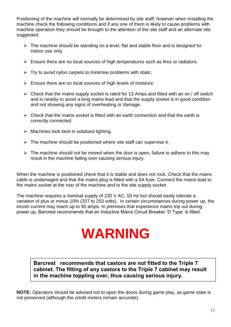
Positioning of the machine will normally be determined by site staff, however when installing the machine check the following conditions and if any one of them is likely to cause problems with machine operation they should be brought to the attention of the site staff and an alternate site suggested: The machine should be standing on a level, flat and stable floor and is designed for
indoor use only. Ensure there are no local sources of high temperatures such as fires or radiators.
Try to avoid nylon carpets to minimise problems with static.
Ensure there are no local sources of high levels of moisture.
Check that the mains supply socket is rated for 13 Amps and fitted with an on / off switch
and is nearby to avoid a long mains lead and that the supply socket is in good condition and not showing any signs of overheating or damage.
Check that the mains socket is fitted with an earth connection and that the earth is
correctly connected. Machines look best in subdued lighting.
The machine should be positioned where site staff can supervise it.
The machine should not be moved when the door is open, failure to adhere to this may
result in the machine failing over causing serious injury. When the machine is positioned check that it is stable and does not rock. Check that the mains cable is undamaged and that the mains plug is fitted with a 5A fuse. Connect the mains lead to the mains socket at the rear of the machine and to the site supply socket. The machine requires a nominal supply of 230 V AC, 50 Hz but should easily tolerate a variation of plus or minus 10% (207 to 253 volts). In certain circumstances during power up, the inrush current may reach up to 95 amps. In premises that experience mains trip out during power up, Barcrest recommends that an Inductive Mains Circuit Breaker ‘D Type’ is fitted.
WARNING
NOTE: Operators should be advised not to open the doors during game play, as game state is not preserved (although the credit meters remain accurate).
Barcrest recommends that castors are not fitted to the Triple 7 cabinet. The fitting of any castors to the Triple 7 cabinet may result in the machine toppling over, thus causing serious injury.

14
3.3 TOP BOX INSTALLATION The instructions in this section are intended as a guide to fitting a Top Box to a Triple 7 cabinet. Standard Top Box Installation. Ensure the 240V mains supply is disconnected from the cabinet before commencing a top box installation. Remove the cover plate from the top of the cabinet by removing the 4 x M6 nuts from the inside of the cabinet as indicated in the images below. Now lift away the cover plate.
Carefully lift the Top Box to the top of the cabinet and feed the wiring through the large centre hole. Align the Top Box bolts with the holes that are situated either side of the large centre hole and locate the Top Box ensuring it sits flush with the top of the cabinet. At this point the Top Box can now be secured to the cabinet using the wing nuts supplied. See first image below.
The Top Box connector is now plugged into the Barbus distribution board. See second image above. Reconnect the mains supply to the machine to ensure the Top Box is working correctly.
Remove 4 x M6 nuts

15
Video Top Box Installation. Ensure the 240V mains supply is disconnected from the cabinet before commencing a top box installation.
Before fitting the Video Top Box to the cabinet, the two stabilising cabinet feet must be fitted using the 4 x M6 bolts supplied as shown in the image below.
Remove the cover plate from the top of the cabinet by removing the 4 x M6 nuts from the inside of the cabinet as indicated in the images below. Now lift away the cover plate.
Carefully lift the Top Box to the top of the cabinet and feed the wiring through the large centre hole.
WARNING! IMPORTANT SAFETY INFORMATION.
Stabilising Feet Fitted.
Remove 4 x M6 nuts

16
Align the Top Box bolts with the holes that are situated either side of the large centre hole and locate the Top Box ensuring it sits flush with the top of the cabinet. The Video Top Box can now be secured to the cabinet using the wing nuts supplied. Once secured the cables can now be connected, The Video Top Box Barbus cable is connected to the Barbus Distribution board as shown in image 1 below and the Video Top Box mains cable is connected to the mains distribution box as shown in image 2.
Now reconnect the mains supply to the machine to ensure the Video Top Box is working correctly.

17
3.4 INFILL PANEL INSTALLATION The instructions in this section are intended as a guide to fitting infill units to adjoining Triple 7 cabinets and must be followed correctly. Failure to do so may result in the assembly becoming unstable and could possibly result in the cabinets toppling over. The Infill Panel installation kit consists of the following parts
1) 1 x Infill Panel 2) 4 x Securing Brackets 3) 12 x M6 Bolts
Barcrest recommends the minimum of two people for the installation of the Triple 7 infill unit. 1. Ensure the 240V mains supply is disconnected from the cabinet before commencing infill installation.
2. Attach one of the securing brackets to the bottom LHS of the Triple 7 cabinet by using two of
the M6 bolts supplied, as shown in the image opposite. Once the bracket is attached, position the machine into place.
3. Attach two of the securing brackets to the top of the Infill unit by using four of the M6 bolts
supplied. As shown in the image below.

18
4. Once the securing brackets have been fastened to the top of the infill panel, fix the remaining bracket to the rear lower LHS of the infill using two of the M6 bolts supplied and manoeuvre it into place next to the cabinet, as shown in the image below.
5. Each Infill panel has two cables attached, feed the grey power cable into the first machine and connect into one of the spare sockets available on the Barbus distribution PCB interface, as shown in the image below. The second braided sync cable is now fed into the second machine and is connected into one of the spare sockets available on the Barbus distribution PCB interface and so on for each infill panel ensuring that only one grey power cable is fitted to each Barbus interface PCB. Fasten the earth tag to the cabinet any loose infill wiring should then be fitted into the existing harness retaining clips.
6. The second Triple 7 cabinet can now be manoeuvred next to the infill unit. Once aligned the
infill unit can be fastened to the cabinets by using the remaining four M6 bolts as shown in the image below.
7. Reconnect the mains supply to ensure the unit is functioning correctly.

19
3.5 TOP BOX AND INFILL POWER SUPPLY FITTING INSTRUCTIONS These instructions are intended as a guide to fitting a 12V power supply kit to MPU6 Triple 7 machines. This kit should only be used for machines that have infill’s and top boxes fitted only. 1. Switch off the machines and ensure that the power supply leads are all disconnected. 2. If the infill panels have not been installed, then please refer to the fitting instructions in
Section 3.4. 3. For each machine open up the top and bottom doors to gain access to the inside of the
machine and then disconnect the main Barbus lead from the Barbus interface PCB as shown in the first image below.
4. Locate the Barbus power extension link from the kit and connect the machines Barbus
connector to the PSU extension leads inline pins taking care that it is connected correctly as shown in the second image below.
Barbus power
extension link
Existing Barbus
lead

20
5. Now connect up the extension links Barbus connector to the Barbus distribution PCB as shown in the first image below.
6. Now run the wiring down the left hand side of the PC and feed the white 4-way connector
through the recess in the bottom of the cab as shown in the second image below.
7. Locate the Sentronics power supply into the base of the cabinet and connect up the
connectors from the PSU and extension link as shown in the first image below. 8. Now feed the mains power supply lead from the PSU through the recess to the left of the
mains distribution panel and then connect it up to the next available outlet on the mains distribution panel as shown in the second image below.

21
4. I BUTTON “DALLAS” KEYS The Triple 7’s cabinet is fitted with 3 IButton receptors, each receptor has its own unique function. IMPORTANT: The two internal attached ‘I button keys’ located next to the Belly Glass and Cash Door receptors are dedicated to the relevant receptor ports. Under no circumstances must these ‘I buttons’ be removed as it will have a detrimental affect on the overall cabinet’s performance.
The External Receptor.
The external receptor has two functions. When the I button is presented to the external receptor with the main menu screen in view with any door open, it will allow the user to access the Refill & Collection screen (Please refer to section 5.7, Customer Collections for further information) When the I Button is presented to the external receptor with all the doors closed it will allow access to the managers refill screen. (Please refer to section 5.8, Customer Refill for further information)
The Internal Main Door Receptor. When the service button has been selected from the main menu screen, the I Button must be presented to the internal receptor to allow access to the service menu screen. (Please refer to section 5.15, Service for further information)
The Internal Cash Box Receptor.
When the user enters the customer collections mode (Section 5.7), the screen will display the current hopper values. By presenting the I Button to the cash box receptor within this screen, the machine will proceed to empty the contents of the hopper currently displayed. (Please see section 5.7 for further information)

22
5. INITIAL POWER UP Each time the machine is powered up a number of automatic resetting and self-checking procedures take place. Except for a short time delay the observer is mostly unaware that these are taking place. If any faults are found during the initialisation period, an alarm is given and the nature of this alarm is shown via the display on the MPU6. Following a successful initialisation with no problems encountered and the machine in a ‘Door Open’ state the screen will display ‘Main Menu’.
5.1 MAIN MENU On opening the main service or cash door you are presented with the main menu screen shown in the image below.
The Main Menu screen allows the user the facility to navigate through the each of the functions of the Triple 7’s cabinet. Each function can be accessed, by pressing the appropriate on screen button. Presenting the I Button to the external receptor from the main menu screen will enable the user access the collection menu (Detailed in section 5.7)

23
5.2 EVENT LOGS Event Logs The event logs enable the operator the facility to view specific events that may have occurred within the normal operation of the machine. This recorded data is compiled into three areas, OPERATOR, GAME LOG and BARBOOT. The following sections cover these areas in greater detail. Operator Log. By selecting Event Logs from the Main Menu screen, the machine will automatically display the Operator Log. The Operator Log details all cash in and out events, any ‘operational’ percentage, stakes and prize changes and all technical related occurrences such door status and hardware failures etc. Each individual event is accompanied with the specific time and date that it occurred. NOTE: To ensure the data compiled in these logs is accompanied with the correct time and date, the clock must be set up correctly. Please refer to the section 5.15 Service, Set Clock. To view the daily events select the arrows on the top left and right hand side of the screen.

24
Game Log By selecting ‘Game Log’ from the Operator Log menu, the screen will now display the Game Log. The Game Log supplies the user with a detailed compilation of each and every game played and any subsequent winnings achieved. NOTE: To ensure the data compiled in these logs is accompanied with the correct time and date, the clock must be set up correctly. Please refer to the section 5.15 Service, Set Clock. Dump Logs The data recorded by the machine can be downloaded to a USB key; this enables the user the facility to extract the machine information, which can then be analysed at Barcrest. To perform this task the following instructions must be followed. From the Technical Log section, press Dump Logs. You will now be prompted to insert a USB key. On detection of the USB key, the machine will automatically download the event logs directly to the USB key. Once all the data has been transferred, the machine will prompt the user to remove the key. Bar boot Log The Bar Boot Log compiles all the information relating to the performance of the PC. This detailed analysis assists Barcrest in identifying problems with the PC, software should one occur. To view the Bar Boot Log, press the Bar Boot button, this is accessible from within the Operator and Game Log pages.

25
5.3 SYSTEM INFORMATION The system information screen is directly accessible from the Main Menu. This screen displays the current configuration set up of the cabinet and allows the user the facility to easily view the installed software and hardware versions.
5.4 SOFTWARE VERIFICATION Software Verification can be accessed via the System Information screen, this facility is used to ensure that all the software currently installed within the cabinet are genuine compliant releases by Barcrest and allows the facility to verify the game(s) to confirm authenticity and compliance.

26
5.5 GAME LICENSING When a new Triple 7 cabinet is purchased from Barcrest, each game installed will have its own unique dedicated licence fitted. The licence guarantees that the game software supplied within the cabinet is 100% authentic and has been supplied by Barcrest. On new machines leaving the factory the licence(s) of the installed game(s) will already be installed. For future game purchases the licence key will be supplied separately with the game software. The following sections detail the processes required to licence any new games. On receiving your new game, you must first check the contents within the kit. USB Game Key USB Game Licence Key Game Update Instructions Game Licence Update Instructions USB Game Licence Key, return sticker.
Once the kit contents have been checked, you can now proceed to load the new game and its licence. Prior to the installation of the Game licence, the user will be required to load and configure the specific game into the game slot. Please refer to Section 5.10 Updates and Section 5.12 Game Configuration to perform this game update and configuration. Once the game has been successfully installed and configured, it is ready to be licensed. From the Main Menu screen, press the ‘Licensing’ button. The screen will now display the ‘Installed Licences’ screen, as shown below.

27
On selection of the ‘Licence Games’ button, the screen will display all games currently installed on the cabinet. On pressing the ‘Licence Now’ button the user will be prompted to insert the game licence key, as shown in the image below.
Once the USB licence key has been inserted, there will be a short pause while the game licence is installed. Following a successful installation the user will be informed that the new licence has been installed. In the event that the licence fails to install error information box will be displayed advising the user of an unsuccessful installation. If this error occurs, the user should restart the game licence installation process.

28
On exiting the ‘Licence Games’ screen, the user will be able to view the newly installed licence by returning to the Installed Licences screen as shown in the image below.
The installation is now complete. To ensure the game has been correctly installed and licensed, close all the machine doors. Following a reset, the newly installed game should now be available for selection from the lower screen. Please ensure your used licence key is returned to Barcrest using address sticker provided.

29
5.6 ACCOUNTANCY The Accountancy menu is selectable directly from the Main Menu screen. On entering the Accountancy Menu, the following meter information will be available. LCD Meters, Long Term Meters and Short Term Meters. These meters can be viewed in £1 Cash or 10p units by selecting the appropriate button.
Detailed Accountancy The ‘detailed’ button when selected from the accountancy screen shows detailed metering information for each game. The metered information is accompanied with the time and date; this allows the operator to monitor income patterns between specific dates. The game information may be viewed by selecting the appropriate left and right arrow icon and all of the relevant coin values can be viewed by using the scroll bar on the right hand side of the screen.

30
5.7 CUSTOMER COLLECTIONS The Collection screen is accessed by presenting the IButton to the external receptor when the ‘Main Menu’ screen is displayed. Once accessed the collection screen shows the hopper balance and divert levels for the £1.00 and 10p Hoppers, including the hopper refill information as shown in the screen shot below. Seven buttons are displayed on the screen as shown below:
1. Other Amount 2. £10.00 (value may differ dependant on machine category and hopper configuration) 3. £20.00 (value may differ dependant on machine category and hopper configuration) 4. £30.00 (value may differ dependant on machine category and hopper configuration) 5. Hopper Top Up 6. Accountancy 7. Next Hopper
Collection By selecting the ‘Collection’ button or by performing a hopper dump the Short Term Meters will reset to zero and the displayed time and date will change to indicate this action has occurred. The Long Term and LCD meters cannot be reset.

31
£10.00/ £20.00/ £30.00 Buttons These buttons give the option of increasing the hopper balance by the value of the button selected. Other Amount Button When the Other Amount Button is selected a numerical keyboard will be displayed on the lower screen as shown below. This function allows the operator the facility to enter a specific cash amount when they are refilling the machine. Once the required value has been entered, the operator must confirm this float amount by pressing the OK button.
Hopper Top Up Button This button is used to top up the hoppers to a predetermined level dependant on the machine settings. The hopper levels can be set to the customer specifications within the Terminal Configuration section. Please refer to section 5.14 Terminal Configuration for more information. Accountancy The Accountancy information is covered in detail in the previous section 5.6. Next Hopper This button is used to toggle between the £1 and 10p hoppers and enables the operator the facility to view the current float levels specific to the hopper selected. Dump Hopper From the Collection screen, the operator can empty the contents of each hopper by presenting the IButton to the receptor situated within the cash box area. Dependant on the hopper displayed on the screen will decide on what hopper is emptied. By selecting the Next Hopper icon and following the previous instructions will empty the second hopper.
Please ensure the main door is closed before emptying the hoppers.
32
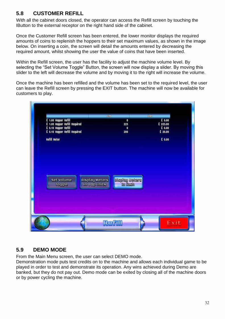
5.8 CUSTOMER REFILL With all the cabinet doors closed, the operator can access the Refill screen by touching the IButton to the external receptor on the right hand side of the cabinet. Once the Customer Refill screen has been entered, the lower monitor displays the required amounts of coins to replenish the hoppers to their set maximum values, as shown in the image below. On inserting a coin, the screen will detail the amounts entered by decreasing the required amount, whilst showing the user the value of coins that have been inserted. Within the Refill screen, the user has the facility to adjust the machine volume level. By selecting the “Set Volume Toggle” Button, the screen will now display a slider. By moving this slider to the left will decrease the volume and by moving it to the right will increase the volume. Once the machine has been refilled and the volume has been set to the required level, the user can leave the Refill screen by pressing the EXIT button. The machine will now be available for customers to play.
5.9 DEMO MODE From the Main Menu screen, the user can select DEMO mode. Demonstration mode puts test credits on to the machine and allows each individual game to be played in order to test and demonstrate its operation. Any wins achieved during Demo are banked, but they do not pay out. Demo mode can be exited by closing all of the machine doors or by power cycling the machine.

33
5.10 UPDATES By selecting the ‘UPDATES’ button from the main menu screen, the operator may update the machine with a new game, game executive or theme. Once the ‘UPDATES’ button has been selected, an on screen prompt will appear to insert the USB key containing the new games/executive/theme. On inserting the USB key, the machine will automatically read the key and will display the contents on the lower screen, as shown below. The operator can now select the file to be copied by selecting the appropriate arrow icon next to the file. Once the file has been selected a text box will open to display a ‘Copy Files’ button, when the ‘Copy Files’ button is pressed, the machine will automatically copy the selected file(s) from the USB key on to the machine ready for configuration, please refer to section 5.11 ‘CONFIGURATION’. When the file transfer process has been completed the machine will display a remove USB key message. Following an executive update the screen will display a ‘Yes’ or ‘No’ reboot message. If ‘yes’ is selected the machine will reboot and load the selected executive. The status of the new executive loading will now be displayed on the top monitor and the machine will automatically reboot when the executive has finished loading. Following a successful executive update the machine will now display the Main Menu screen. DO NOT SWITCH OFF THE MACHINE DURING AN EXECUTIVE UPDATE, AS IRREVERSIBLE DAMAGE TO THE PC HARD DRIVE MAY OCCUR. If no is selected the new executive will be loaded following the next power cycle.
IMPORTANT!
Select To
Copy

34
5.11 CONFIGURATION Configuration is selectable from the Main Menu screen and comprises of three sections Game, Terminal and Theme Configuration. In the following sections the information will detail the functionality of these areas to allow the operator to set up their new cabinet to their required site specifications.
5.12 GAME CONFIGURATION Once the Game has been loaded on to the cabinet as described in section 5.10 ‘UPDATES’, it is now ready to be installed, enabled and configured into one of the game slots. The next three stages detail this process. INSTALLING THE GAME From the main menu screen select “Config” then select the “Game Configuration” button. The following screen titled Games will now be displayed on the lower monitor. The Games screen details what games are already installed on to the cabinet and also shows the game slots available to load new games. On selection of the ‘Load’ icon, the lower monitor will display all available games that have been updated on to the cabinet and are ready to be installed into the required game slot.
On selecting of the appropriate ‘install arrow’ icon next to the required game, the machine will automatically install this into the selected game slot, as indicated in the image below.
Load Icon

35
For example if Monty Python were to be installed into game slot 5, the ‘install arrow’ icon indicated below would need selecting.
ENABLING THE GAME To enable the game select the ‘enable’ icon as indicated in the image below to change the enabled message from ‘No’ to ‘Yes’.
Install Icon
Enabled Icon
Enabled Status

36
CONFIGURE GAME To change or review the game configuration settings, select the ‘config arrow’ icon indicated in the image below in the games menu.
Once the ‘config arrow’ icon has been selected, the lower screen will display the current settings applicable to the installed game. The operator may change these settings to their required site specifications by using the appropriate arrow keys.
Config Arrow Button
37
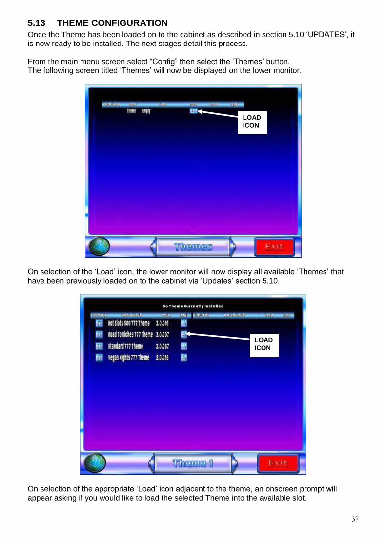
5.13 THEME CONFIGURATION Once the Theme has been loaded on to the cabinet as described in section 5.10 ‘UPDATES’, it is now ready to be installed. The next stages detail this process. From the main menu screen select “Config” then select the ‘Themes’ button. The following screen titled ‘Themes’ will now be displayed on the lower monitor.
On selection of the ‘Load’ icon, the lower monitor will now display all available ‘Themes’ that have been previously loaded on to the cabinet via ‘Updates’ section 5.10.
On selection of the appropriate ‘Load’ icon adjacent to the theme, an onscreen prompt will appear asking if you would like to load the selected Theme into the available slot.
LOAD ICON
LOAD ICON

38
By selecting the ‘Yes’ button the selected Theme will now automatically load.
Once the chosen Theme has successfully loaded it will now be displayed as the default Theme.

39
5.14 TERMINAL CONFIGURATION By selecting terminal configuration from the config screen, the operator will have the facility to adjust or view specific machine settings that are currently configured within the cabinet, as described below. General Settings: Volume Adjust – Attract Mode Adjust – Event Log Archive Adjust. Machine Details.
Operator Configuration: Cash Limits – Operator Category – Note Configuration –
Payout Devices Multi Player Settings: DHCP set up.
GENERAL SETTINGS By selecting the General Settings button from the Terminal Config, the following functions may be adjusted. Volume Adjust The volume level is controlled via the slider bar. By moving this slider to the left will decrease the volume and by moving it to the right will increase the volume. Attract mode The attract mode timing can be set by moving the slider from left to right to increase or decrease the time for the attract mode to be enabled. Event Log Archive. This function allows the operator the facility to determine the timescale they wish to keep previous day’s event data. This archive event data can be kept from 30 – 60 days. By moving the slider to the left will decrease the number of days to a minimum of 30, by moving the slider to the right will increase the number of days to a maximum of number of 60.
40
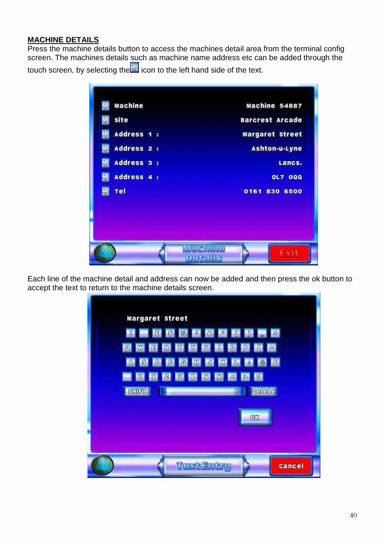
MACHINE DETAILS Press the machine details button to access the machines detail area from the terminal config screen. The machines details such as machine name address etc can be added through the
touch screen, by selecting the icon to the left hand side of the text.
Each line of the machine detail and address can now be added and then press the ok button to accept the text to return to the machine details screen.

41
OPERATOR CONFIG By selecting the ‘Operator Config’ button from Terminal Config, the following functions may be adjusted. Cash Limits By selecting Cash Limits from the Operator Config screen, the user will be able to view the current set bank and credit limits including direct pay settings.
Operator Category By selecting ‘Operator Category’ from the Operator Config screen, the user can view the machines current configuration.

42
Note Acceptor Configuration On selection of the ‘Note Acceptor Configuration’ button, the user has the facility to adjust the level that the note acceptor cuts off. This level may be adjusted by either moving the slider left to decrease the value or right to increase, or alternatively the + or – icons may be used. By selecting the ‘enable’ icon, the tick symbol will change to a cross, at this point the note acceptor will be disabled.
Payout Devices By selecting Payout Devices from the Operator Config screen, the user will be able to adjust the Hopper float/divert levels and Handpay settings to their own specific site specifications. The note payout button is only available when a note payout device is fitted.

43
Note Payout configuration If the note denomination is to be changed then the note payout unit must be emptied into the stacker
using the dump hopper button procedure as described in the collection procedure in section 5.7. When
the note payout configuration button is selected, the operator can set £10 or £20 note denomination
payout as required.

44
Hopper Configuration By selecting the ‘Hopper Configuration’ button from the Payout Devices screen the user can configure the machines hopper float levels. Once selected the lower screen will display the current set values of both hoppers along with the set divert levels. It is important to set the correct Hopper divert value first, as the Hopper float value cannot exceed the divert level. The hopper levels may be adjusted by either moving the slider left to decrease the value or right to increase, or alternatively the + or – icons may be used.
The float level is the amount of coins that the user has placed into the hopper. The divert level is the maximum number of coins allowed in the hopper before coins are
diverted to the cash box.
Hand Pay Hand Pay enables operator the facility to pay any winnings to the player by hand, via refill. Once selected the operator must specify the amount to be paid to the player by the hopper unit, this value can be adjusted be using the + and – buttons or the slider bar until the required amount is set. Any funds collected greater than the set hopper payout level will be paid to the player via hand pay. The benefit of hand pay enables the machine to run on a reduced hopper float if required and reduces the levels of hopper refills. Hand Pay functionality is only recommended for premises that have machine attendants available to payout any winnings to the players.

45
5.15 SERVICE By selecting the ‘SERVICE’ button from the main menu screen, the operator will be prompted to locate the I Button key to the Main Door internal receptor. Once the I Button key has been located and verified, the service screen will be displayed on the bottom screen. The Service menu enables the operator the facility to test individual components within the cabinet, these functionality tests are. Audio Test Video Test Set Clock Update MPU Touchscreen test Test LEDS Validators Test Serial setup Hoppers Test Switch Test Meters Test Dataport Test Ticket Printer Machine Comms Test
46
Audio Test On selection of the ‘audio’ button the user can test the left and right channels separately then both channels together by pressing the appropriate on screen button. Video test The ‘Video Test’ consists of six screens
1. Monitor alignment screen 2. White (Pixel fault detection screen) 3. Black (Pixel fault detection screen) 4. Red (Pixel fault detection screen) 5. Green (Pixel fault detection screen) 6. Blue (Pixel fault detection screen)
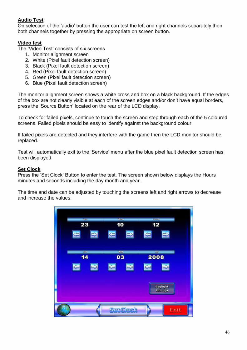
The monitor alignment screen shows a white cross and box on a black background. If the edges of the box are not clearly visible at each of the screen edges and/or don’t have equal borders, press the ‘Source Button’ located on the rear of the LCD display. To check for failed pixels, continue to touch the screen and step through each of the 5 coloured screens. Failed pixels should be easy to identify against the background colour. If failed pixels are detected and they interfere with the game then the LCD monitor should be replaced. Test will automatically exit to the ‘Service’ menu after the blue pixel fault detection screen has been displayed. Set Clock Press the ‘Set Clock’ Button to enter the test. The screen shown below displays the Hours minutes and seconds including the day month and year. The time and date can be adjusted by touching the screens left and right arrows to decrease and increase the values.
47
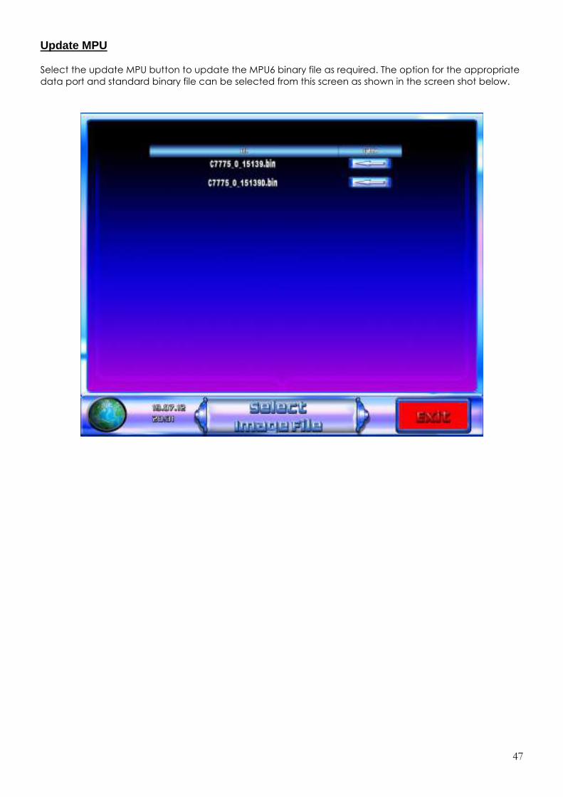
Update MPU
Select the update MPU button to update the MPU6 binary file as required. The option for the appropriate
data port and standard binary file can be selected from this screen as shown in the screen shot below.

48
Touchscreen Test
Select the Touchscreen test button from the service menu to enter the Touchscreen calibration screen.
Select the red buttons on the Touchscreen to calibrate. Now select the flashing start button to accept
the calibration and exit the screen.

49
Test LEDS On selection of the ‘Auto Step LEDs’ button, the machine will automatically step through each LED and illuminate accordingly, the appropriate lit LED will also be displayed on the bottom monitor for reference. By selecting the ‘Flash LEDs’ button, the machine will illuminate all LEDs within the cabinet. On selection of the ‘Manual Step LEDs’ button, the user can step through each LED ensuring all are fully operational. The Belly, Plinth doors and Infill LEDs can be tested by selecting the relevant button. Select the “Exit” button to go back to the previous service menu.

50
Validator Test On selection of the ’Validator test’ button, the operator can ensure the note acceptor and coin mechanism are functioning correctly. Once a coin or note has been inserted and accepted the appropriate monetary value will be displayed on the bottom monitor as shown below. The divert button allows the operator to test the coin mechanism’s separator to either divert coins to the hoppers or divert the coins directly to the cash box.

51
Serial Device set up test This menu is used to set up the encryption code for a replacement coin or note acceptor. This may also be required after a MPU6, PC change and executive update. The screen below shows both the note acceptor and coin mech codes. The codes are entered by selecting the serial number entry icons indicated in the image below. One the appropriate codes have been entered then select the relevant set up icon. Once selected an icon will appear on the screen to indicate that the code has been accepted by the machine. Select ok on the button and the machine will initialise. Once the machine has set up check, the coin and note handling devices to ensure that they operate correctly.
Serial number entry icons

52
Hopper Test By selecting the hoppers test button from the Service menu, the operator can test the hopper payouts to ensure they are functioning correctly. On entering the screen, the operator will be presented with four on screen buttons. These buttons allow the user to pay an individual coin or a multiple of 20 coins if selected. The value of the paid out coins is then displayed to operator to reconcile the correct amount of coins has been paid out. As shown in the screen below.

53
Switch test On selecting ‘Button Test’ a pictorial representation of the machines physical buttons and switches, is displayed as shown in the image below. Activating the machines physical buttons/switches will cause its pictorial representation to be highlighted, indicating that the button/switch is functioning correctly. Door switches are not included in this test as they cause the machine to toggle between door open and normal operation.
Meter Test Press the meter test button to enter the test. During the test, the screen displays ‘Testing’ then ‘Test Passed’ or ‘Test Failed’ as appropriate. Start Test button to repeat the test Dataport Test On selecting ‘Dataport Test’ the machine will proceed to test the Dataport interface. A Dataport compliant device must be connected to the MPU6 for this test to succeed. During the test, the screen displays ‘Testing’ then ‘Test Passed’ or ‘Test Failed’ as appropriate. Press the ‘Test Dataport’ button to repeat the test. Ticket Printer On selection the machine will now allow the user to test print. Press the ‘Ticket printer button to repeat the test. Machine Comms Test To test the machines comms when connected to a server or top box then select the machine comms test button. If the comms are successful then a pass message is displayed or if unsuccessful in the event of a problem then a fail message will be displayed.

54
Section B
MAINTENANCE INFORMATION
1. INTRODUCTION The following sections detail the functionality of each of the main components within the Triple 7’s cabinet. The instructions within these sections will allow a competent engineer to perform essential maintenance and will also aid in fault finding should a machine malfunction occur.
2. MPU 6 SYSTEM The MPU 6 system is a modular system comprising a number of key modules that in combination provide a flexible, reliable I/O for the Triple 7’s cabinet.
The key modules are as follows: 1. MPU6 board 2. LED driver board 3. Switch mode power supply
The key modules are interconnected by a proprietary Barbus power/data link, which provides D.C. power supply routing and integrates the modules into a working system. Each end of the Barbus data link is terminated at the PSU interface board.
MPU6 Board The MPU 6 board offers numerous enhancements from its reliable & robust MPU5 ancestor, these include an integrated on board 16 character LCD display with backlight and menu buttons, increased processor power, additional memory and USB connectors. The MPU6 board is a single board controller comprising of a microprocessor, memory, Barbus power/data link, 2 x USB ports, SP/DIF input, Dataport, Stakes & prizes & percentage key sockets and a main 64 way connector connector for driving numerous peripheral devices and for receiving inputs from switches and pushbuttons etc. To interface to the outside world these connectors are mounted around the periphery of the unit, ensuring good mechanical support when plugging or unplugging thus minimising flexing of the PCB. The MPU6 board and its enclosure are fixed to the cabinet via two M4 screws.
USB A PORT STAKES & PRIZES PORT
% KEY PORT
DATAPORT CONNECTOR
USB B PORT
S/P DIF Input
64 WAY INPUT/OUTPUT CONNECTOR
ON BOARD MENU BUTTONS
POWER STATUS INDICATORS
BARBUS INTERFACE
16 CHARACTER LCD DISPLAY PANEL.

55
The MPU6 unit has the following connections & functionality. 16 character LCD display
The LCD display shows the current status of the MPU6, in the event of a peripheral device failure such as a ‘coin mech jam’ the appropriate error message will be shown on the display. (Please refer to section 2.1 MPU 6 fault codes).
USB A Port.
The USB A port allows the operator the facility to update the MPU6 board via a USB stick. MPU6 updates are normally performed during a PC executive update. Should the need arise to update the MPU6 outside of a PC executive update, for example changing from Data to Non Data the following process should be followed.
1. Power down the machine 2. Insert the USB stick into USB port A 3. Power up the machine. 4. Using the up/down on board menu buttons go to the section titled ‘BOOTSTRAP’
and press enter. 5. Using the up/down on board menu buttons select the appropriate file to be loaded
and press enter. 6. The MPU6 will now update with the selected file, once finished remove the USB
stick and power down. 7. Following approx 10 seconds power up the cabinet, the new software will now be
loaded.
In the event that the MPU6 requires a full reset, a ‘Clear Down’ USB stick will be required from Barcrest After Sales and the following process must followed.
1. Power down the machine 2. Insert the USB ‘Clear Down’ stick into USB port A 3. Power up the machine 4. The LCD display will now show ‘Clear Memory’ 5. Press the enter button and the MPU6 will now clear. 6. Power down the machine and remove the USB ‘Clear Down’ stick 7. Re apply the power to the machine and test thoroughly.
USB B Port
This connector interfaces directly with the PC to allow communication between the two units
Stakes & Prizes Port
On UK machines only, the price of play (stake) and jackpot options are set by plugging a stake/jackpot key into a 9-way D-type STAKE/JACKPOT plug on the MPU6. A range of colour coded and labelled keys are available from Barcrest Aftersales. This function is not used on the Triple 7 cabinet
Percentage Key Port On UK machines the target payout percentage can be set by plugging a percentage key into a 9-way D-type PERCENTAGE socket on the MPU6. A range of keys from 70% to 98% payout are available from Barcrest Aftersales. This function is not used on the Triple 7 cabinet.

56
Dataport Connector
To enable the MPU6 to be easily and securely interfaced to a Datapak, which may be specified to back up the electronic metering and provide a downloadable machine event store, an industry standard Dataport is fitted. This comprises of a 25-way D-type socket, identified on the MPU6 cover, for serial transmit/receive signals and with +12V and -12V power supplies, as shown in the image below.
The Dataport is also compatible with the RS232C standard used as a serial interface throughout the electronics industry; this provides an easy means of connecting peripheral devices such as printers, terminals and modems.
Barbus interface The proprietary Barbus is a combined power bus and serial data link connected in a daisy chain layout between the machine modules. The Barbus is connected to the MPU6 board via a red 11-way BARBUS connector.
S/P DIF Input
The S/PDIF interface (Sony Philips Digital Interface), is used to provide compressed digital audio for the machines stereo speakers. Also it can receive external audio from other equipment and played through the machines stereo speakers.
Power Status Indicators The power status indicators monitor the supply rails to ensure the correct operating voltages are present. In normal operation all LEDs should be lit, in the event that one of the supply voltages has failed the appropriate led will not illuminate.
64 WAY Input/Output connector
The 64 way connector drives numerous peripheral devices such as the note acceptor, ticket printer, meters, CCtalk devices and is used for receiving inputs from switches and pushbuttons etc.

57
2.1 MPU6 FAULT CODES
Alarm Messages When an alarm occurs during normal operation an error message is shown on the integrated LCD display of the MPU6. The message generally comprises of three parts, which are displayed in succession. The display shows the alarm number, e.g. ALARM 54 – 11 – CPU BUS ERROR The first two digits are the BACTA industry alarm code. The second two digits are the Barcrest alarm code. The third part is a brief description of the fault encountered. Class of alarm The various alarms, which can occur on the MPU6 system, are grouped into TEN classes. When a fault occurs, the first digit of the Barcrest alarm number shows the class of alarm A complete list of alarm messages, related to the associated BACTA and Barcrest fault code numbers are shown in the following sections. Class 1 alarms Known as processor exceptions, these are errors detected by the CPU. They can be caused by hardware faults in components on the CPU bus, e.g. CPU, RAM, PROMs, and DUART etc. When shown on the display these alarms range from 11 - 1E with a Bacta code 54
BACTA. Code BARCREST No. MESSAGE 54 11 CPU BUS ERROR 54 12 ADDRESS ERROR 54 13 ILLEGAL INSTRUCT 54 14 DIVIDE BY 0 54 15 BOUNDS CHECK 54 16 OVERFLOW TRAP 54 17 BAD INTERRUPT 54 18 UNUSED TRAP 54 19 BAD STACK FORMAT 54 1A UNINIT IVECTOR 54 1B PRIV VIOLATION 54 1C TRACE EXCEPTION 54 1D BREAKPOINT 54 1E RESERVED VECTOR 54 1F WATCH DOG RESET

58
Class 2 alarms These are caused by hardware faults on the MPU5 board. Most alarms of this class are generated during power up self-test. When shown on the display these alarms range from 21 - 2F with a Bacta code 31, 32, 53 or 54
Class 3 alarms These are caused by faults on the MPU6. When shown on the display these alarms range from 31 - 36 with a Bacta code 51 or 52 Class 4 alarms These alarms are the result of inconsistencies detected during software checks. These can be caused by software bugs or hardware problems with the memory. When shown on the display these alarms range from 41 – 4E with a Bacta code 42, 48, 53 or 90.
Bacta Code Barcrest No. Message 53 21 RAM TEST FAILED 54 22 BARBUS FAILED 54 22 CPU PIT FAILED 54 22 CPU UART FAILED 54 23 MPU6 UART FAULT 54 24 ASIC TEST FAILED 54 25 MSP430 FAILED 54 2A METER SENSE FAIL 54 2A LCD METER FAIL 54 2A LCD METER CHANGED 54 2B RTC FAILED 42 2C MPU6 BATTERY 54 2F USBDEV PORT FAIL
Bacta Code Barcrest No. Message 51 31 PROM CHECKSUM 51 32 PROM INTEGRITY NO DSP 51 32 PROM MISSING 51 33 MISSING APP PROM 51 34 PROMS MISPLACED 51 35 PROMS SWAPPED 52 36 NO ID CELL 52 36 BAD ID CELL 52 36 INVALID ID CELL 52 36 WRONG ID CELL
Bacta Code Barcrest No Message 90 41 SOFTWARE CHECK 90 42 STACK ERROR 90 43 STACK OVERFLOW 53 44 INSUFFICIENT RAM 90 45 SOFTWARE WARNING 90 46 VERSION UPDATE 90 47 RANGE CHECK 42 48 MEMORY CORRUPT 48 49 TAMPER CHECK 45 4A NEW SJ KEY 90 4B FLASH UPDATE 90 4B IRDA ACCESS 90 4C BOUND ERROR 90 4D UNUSED INPUT 90 4E UNUSED MEMORY
59
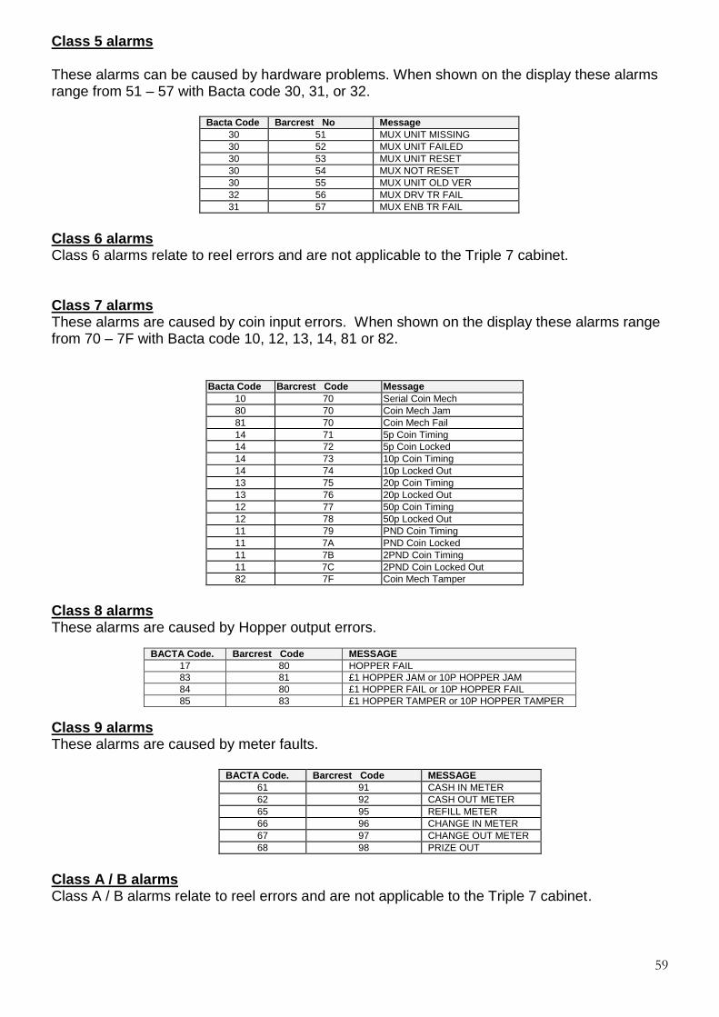
Class 5 alarms These alarms can be caused by hardware problems. When shown on the display these alarms range from 51 – 57 with Bacta code 30, 31, or 32.
Bacta Code Barcrest No Message 30 51 MUX UNIT MISSING 30 52 MUX UNIT FAILED 30 53 MUX UNIT RESET 30 54 MUX NOT RESET 30 55 MUX UNIT OLD VER 32 56 MUX DRV TR FAIL 31 57 MUX ENB TR FAIL
Class 6 alarms Class 6 alarms relate to reel errors and are not applicable to the Triple 7 cabinet. Class 7 alarms These alarms are caused by coin input errors. When shown on the display these alarms range from 70 – 7F with Bacta code 10, 12, 13, 14, 81 or 82.
Bacta Code Barcrest Code Message 10 70 Serial Coin Mech 80 70 Coin Mech Jam 81 70 Coin Mech Fail 14 71 5p Coin Timing 14 72 5p Coin Locked 14 73 10p Coin Timing 14 74 10p Locked Out 13 75 20p Coin Timing 13 76 20p Locked Out 12 77 50p Coin Timing 12 78 50p Locked Out 11 79 PND Coin Timing 11 7A PND Coin Locked 11 7B 2PND Coin Timing 11 7C 2PND Coin Locked Out 82 7F Coin Mech Tamper
Class 8 alarms These alarms are caused by Hopper output errors. Class 9 alarms These alarms are caused by meter faults.
BACTA Code. Barcrest Code MESSAGE 61 91 CASH IN METER 62 92 CASH OUT METER 65 95 REFILL METER 66 96 CHANGE IN METER 67 97 CHANGE OUT METER 68 98 PRIZE OUT
Class A / B alarms Class A / B alarms relate to reel errors and are not applicable to the Triple 7 cabinet.
BACTA Code. Barcrest Code MESSAGE 17 80 HOPPER FAIL 83 81 £1 HOPPER JAM or 10P HOPPER JAM 84 80 £1 HOPPER FAIL or 10P HOPPER FAIL 85 83 £1 HOPPER TAMPER or 10P HOPPER TAMPER

60
Class C alarms Class C alarms relate to note acceptor faults. When shown on the display these alarms range from C0 to CF, with Bacta code of 16.
BACTA Code Barcrest Code Message
16 C0 Serial Note Mech 16 C1 5 PND NOTE TIMING 16 C2 5 PNDNOTE LOCKED OUT 16 C3 10 PND NOTE TIMING 16 C4 10 PND NOTE LOCKED 16 C5 20 PND NOTE TIMING 16 C6 20 PND NOTE LOCKED 16 CF NOTE MECH STRIM 87 C0 NOTE MECH FAIL 84 80 VEGA NOTE PAYOUT FAIL 86 60 NOTE JAM UNSAFE 90 41 SPUR CHARS 28
Class D alarms Class D alarms note input alarms procedural events.
BACTA Code Barcrest Code Message 41 D1 REFILL TURNED 45 D2 NEW OPTIONS 47 D3 REFILL NEEDED 40 D4 DOOR NOT LOCKED 40 D5 DOOR LOCKED
Class E alarms Class E alarms relate to card or ticket vend events. When shown on the display these alarms range from E1 to E4, with a Bacta code of 90.
Class F alarms – Netplex These alarms are caused by note acceptor faults.
BACTA Code BarcrestCode MESSAGE 90 F2 VALIDATOR VER 90 F3 VALIDATOR ERROR 90 F4 STACKER ERROR 90 F5 STACKER FULL 90 F6 STACKER LEVER 90 F7 STACKER OPEN 90 F8 VALIDATOR ERROR 90 F9 VALIDATOR JAM 90 FA NOTE TAMPER
Bacta Code Barcrest code Message
90 E1 VENDER STUCK 90 E2 VENDER BROKEN 90 E3 PRIZE NOT TAKEN 90 E4 TICKET JAM

61
3. PC INFORMATION
This section describes how to remove and fit a replacement PC.
1. With the machine powered OFF, Open the main service door. 2. Disconnect all the cables and leads from the top and bottom of the PC noting where they
were connected, as this will be needed when replacing the PC.
3. The case mountings for the bottom M4 fasteners are slotted so that they support the PC case prior to removal.
4. Loosen off the two M4 nuts that fix the bottom of the PC in position indicated in the image
below, as these will be needed to support the PC prior to removal.
5. Remove the two top M4 nuts indicated in the image above, taking care to support the PC. Now that the two top fasteners have been removed, lift the PC upwards away from the two bottom supporting M4 nuts.
6. Replace the PC and reverse steps 1 – 5 given above, then power up the machine and
then fully retest.
BOTTOM Slacken off nuts.
TOP Remove nuts

62
The following diagram details the connections to the PC, all connectors must be fitted before machine power up.

63
4. POWER SUPPLY INFORMATION This section contains the specification of the Power Supply currently used in the Triple 7 cabinet. The PSU supplies the power to the MPU6 system only. The PC and monitors are powered independently. Input Requirements
Requirement Nominal Range
Input Voltage AC 230V AC150V to AC264V Input Current 2.5A at nominal input
voltage and nominal load
Power Factor 90% Min, input voltage range Frequency 50/60Hz 47 to 63Hz Phase Single Inrush Current 40A o-pk max. Leakage Current 0.75mA max. at nominal load and
normal temperature Hold-up Time 150ms min. from switch off to 90% of
nominal input/output Connector: Panel mounted EURO
NB: Must allow free range 150/230VAC operation without a selector switch
Output Requirements
Nominal Voltage (V)
Total Reg. (%)
Min Load (A)
Nominal Load (A)
Peak Load (A)
Ripple Noise (mV p-p)*4
H.F. Noise (mV p-p)*4
+13 ±5 0 7 10*1 300 1000 -12 ±5 0 0.25 - 300 500 24 ±5 0 0.25 7*2 300 1000 37 ±5 0 5 20*3 300 1000
Output Connector
Pin 1 GND Pin 2 24V Pin 3 24V Pin 4 GND Pin 5 GND Pin 6 GND Pin 7 GND Pin 8 GND Pin 9 13V Pin 10 13V Pin 11 13V Pin 12 -12V Pin 13 KEY Pin 14 KEY Pin 15 37V Pin 16 37V Pin 17 -12V RTN

64
5. MONITOR INFORMATION The Triple 7 cabinet is fitted with two 19” High Definition monitors; the bottom monitor also has an integrated touch screen fitted. Both monitors are powered via the monitor 240V AC / 12 DC transformer as shown in the image below.
The following sections details how to change over a monitor in the event of failure and the process required to recalibrate the lower monitor. Ensure the power has been disconnected to the cabinet. Unplug the VGA cable and the 12V supply cable from the bottom of the monitor as shown below.
Monitor 12V Supply
Disconnect

65
Each monitor is held in position via 6 fixing bolts as shown in the image below.
To remove the monitor from the main door, unscrew the 4 side screws first and then proceed to remove the 2 remaining screws whilst carefully taking the weight of the monitor as shown in the images below.
Remove screws x 6
Remove screws x 6

66
5.1 TOUCH SCREEN CALIBRATION
Following the replacement of the lower touch screen monitor or in the event of calibration errors, a touch screen calibration will be required. To perform this action the following steps must be followed.
1. From the door open menu press and hold the start button, after approximately 8 seconds the machine will enter the touch screen calibration routine.
2. The following message will now appear first on the top screen:
“Touch the touch screen when the correct monitor is highlighted”
”This one”
3. The message has a 3 second countdown. After completing the countdown, the message
is cycled to the next monitor. 4. When the message is displayed on the monitor that has the touch screen installed,
TOUCH the screen. The text of the message will turn RED to confirm that the touch has been detected.
5. The screen will display two touch position dots, one in the lower left corner, and one in
the upper right corner.
6. Starting at the lower left touch position dot, follow the on screen prompt to “Touch and hold for 2 seconds”. On removing finger from screen the message “Thank you” will be displayed, repeat process for upper right touch position dot.
Following a successful touch screen calibration, the screen will now display the main menu.

67
6. ENCRYPTED COIN MECHANISM REMOVAL AND SET UP INFORMATION
6.1 Introduction The encrypted coin mechanism used within the Triple 7 cabinet is the SR3e, manufactured by Crane (Money Controls Limited) as shown below. It is identified by the red clip and currency label indicated in the image below.
The SR3e incorporates the highest levels of discrimination and functionality and will accept up to 12 different coins from 15mm-31mm in diameter. The following diagram illustrates the path of an inserted coin. If the coin is valid it will be diverted down either path 1, 2 or 3. If the mech sees the coin as invalid it will be rejected.

68
6.2 Coin mech Removal The mech can be removed for maintenance or replacement by using the following steps. Remove the mech by pulling the centre forwards, this will then allow access to the connectors at the rear. Unplug the two connectors as indicated in the image below and then lift the mech upwards out of its bracket.
To refit the coin mech reverse steps 1 – 2, ensuring that the mech is refitted securely back into position.
6.3 SR3e Encryption Key Reset Procedure These instructions are intended as a guide to resetting the SR3e coin mech’s encryption key as necessary. The link (Part Number HL71868) is shown in the first image below. 1. Turn the power off to the machine and then open the machines main door. 2. Remove the SR3e mech from the retaining cradle and then disconnect the sorters 10-way
connector, leaving the Mech’s power connector in position. 3. Connect the encryption reset lead between large 10-way sorter socket on the sorter and the
small 10-way coin mech service port as shown in the second image below, taking care to locate the connector in the correct position with the pip at the top.
4. Power up the machine and the LED on the mech will now flash very quickly between red /
green three times and then the red LED will stay on to indicate that the encryption key has now been reset. Now follow the instructions setting the coin mech encryption in section 6.4.
Unplug Connectors

69
6.4 Replacement Encrypted Coin mech set up
Following the installation of the new Encrypted SR3e coin mech and executive software, any future coin mech failures that result in a replacement mech having to be fitted must have the encryption key reset prior to installation. Encrypted SR3e coin mechs that have been initialised within a Triple 7 machine cannot be swapped into another machine, unless the encryption key has been reset. New replacement SR3e coin mechs with the encryption key reset are available from Barcrest Aftersales. From the ‘MAIN MENU’ select the ‘SERVICE’ button as shown in the image below and enter the service menu by confirming via the internal IButton. Select ‘SERIAL DEVICES SET UP” from the ‘SERVICE MENU’ as described in section 5.15. A Button will now be displayed in the centre of the screen saying “Coin Mech initialisation complete press ok to reboot”. When selected the machine will now reset. Once the machine has initialised select the ‘SERVICE’ button from the ‘MAIN MENU’ screen and test the new Encrypted SR3e Coin Mech in ‘VALIDATOR TEST’ to ensure it is functioning correctly. If the mech fails set up then repeat the procedures listed in this section.
6.5 Serial Devices Set up To set up the coin mech or note acceptor, enter the main menu and then select the serial devices button as indicated below.

70
This menu is used to set up the encryption code for a replacement coin or note acceptor. This will also be required after a Mech, MPU6 or PC change. The screen below shows both the note acceptor and coin mech codes. The codes are entered by selecting the serial number entry icons indicated in the image below. One the appropriate codes have been entered then select the “Coin mech set up” icon. Once selected an icon will appear on the screen to indicate that the code has been accepted by the machine. Select the ok button and the machine will now reboot. Once the machine has set up check, the coin and note handling devices in "VALIDATOR TEST" from the main menu to ensure that they operate correctly.
Serial number entry icons

71
7 NOTE ACCEPTOR INFORMATION
The Triple 7’s cabinet is fitted with the Ardac Elite note acceptor manufactured by CRANE (Money Controls Ltd).
The Ardac Elite utilises advanced technology sensing techniques. Has the ability to accept notes regardless of the note position in bezel or angle of
insertion. Has exceptional data processing speeds.
Multiple wavelength note illumination to utilise available security features in bank notes.
Full area note scan allows unrivalled flexibility and capability to reject counterfeits.
Can accept 64 different notes in 4 directions.

72
The following steps must be followed to remove the Ardac note acceptor from the machine for maintenance purposes
1. Locate the Ardac Elite Note Acceptor and disconnect the bezel connector. As shown below.
2. To remove the note acceptor from its assembly, lift the red handle and pull the acceptor forwards, as shown below.

73
3. To open the acceptor for cleaning & maintenance press the red catches and lift the head
up, as shown below.
Once opened, the acceptor may now be cleaned or in the event of a note jam the obstruction can be cleared. The following diagrams detail the internal functionality of the acceptor.

74
In the event of failure the following diagnostics diagram details the status of the Ardac Elite acceptor. DIAGNOSTIC INTERFACE

75
7.1 NV11 NOTE ACCEPTOR MAINTANANCE In the event of a note jam within the Innovative NV11 note acceptor or recycler then follow the instructions given in the following section.
Before starting work on the NV11, disconnect the power to the machine and open the machines main door. Firstly slide the red locking mechanism to the left hand side as shown in the first image below and then lift the top of the NV11 as shown in the second image below. Any notes jammed can now be removed.
Red Configuration
button

76
7.1.1 NV11 Note acceptor removal To remove the NV11 note acceptor to gain access to the note float unit it will be necessary to remove the four M4 fasteners from under the note acceptor mounting bracket. Once the fasteners are removed disconnect the note acceptor and lift the acceptor upwards and place to one side.
7.1.2 NV11 Note Float jam removal. In the event of a note jam within the rear of the note float unit, remove the note acceptor from the machine as described in section 7.1.1. Then squeeze together the two red catches and open the rear door as shown in the first image. Remove the jammed notes if possible taking care not to damage the note transport tape shown in the second image below.
7.1.3 Manual Note Removal If the notes have to be manually removed due to a faulty note acceptor, locate and remove the manual de-float tool shown in the first image below and remove it from its holder then insert it in the location indicated in the second image below. The tape has to be wound by the de-float tool anti-clockwise taking care not to over-wind the tape. The notes will be unloaded to the bottom of the note float unit and into the main body of the acceptor if fitted.
De-float tool

77
Please note: The tape must not be wound past the horizontal markers shown in the second image in section 7.1.2 These markers are used by the float unit’s opto sensors as a parking position once the notes have been removed. If the tape is wound to far then the float unit needs to be returned to innovative for repair.
7.1.4 NV11 BNV Reset procedure To reset the note acceptors BNV code remove the acceptor as described in section 7.1.1 remove the float unit form the top of the acceptor by unclipping the retaining clips from both sides of the acceptor. Select the red configuration button on the main unit and hold in position. Turn on the machines power and then release the button after 5 seconds. The acceptors bezel will now strobe and the unit will reset. Reconnect the float units and then refit into the machine. The BNV key will now be set to the factory setting. Before setting the key check the interface setting is still CCtalk by double clicking the red configuration button. The bezel should flash 6 times. If not then hold the configuration button for 5 seconds until the bezel lights up the release the configuration button. The NV11 will now reset. Double click the red configuration button and ensure that the bezel flashes 6 times. To set up the note acceptor device see section 6.5 for instructions.

78
7.2 JCM VEGA NOTE ACCEPTOR MAINTANANCE In the event of a note jam within the Vega note acceptor or recycler then follow the instructions given in the following section. Before starting work on the VEGA, disconnect the power to the machine and open belly glass door. Vega Note acceptor removal To remove the VEGA note acceptor it will be necessary to remove the four M4 fasteners that fix the acceptor base to the cabinet metalwork. Firstly open the lock shown in the first image below and then remove the note stacker from the note acceptor retaining bracket as shown in the second image below. The four M4 fasteners can now be removed using a 7mm spanner.
VEGA Note Acceptor Jam Main Body In the event of a note jam within the VEGA note acceptors main body press in the two white catches indicated at the front of the VEGA acceptor as shown in the first image below and lift the body up as shown in the second image below to access and remove a jammed note.

79
Vega Note Acceptor Rear Jam Removal. If the note jam is at the rear of the VEGA note acceptor then press in the two white buttons indicated in the first image then remove the blue cover to allow inspection as shown in the second image below. Now refit the access plate back in the correct position as shown in the second image below then click back into place.
JCM VEGA note recycler jam removal. In the event of a note jam within the rear of the recycler unit, lift the white latch as shown in the first image below to the rear of the recycler unit and remove the note if possible taking care not to damage the note transport tape. If necessary remove the blue maintenance cover on the left hand side of the note recycler unit to enable access the manual gear control knob rotating it anti clockwise to remove. To aid removal of a jammed note rotate the gear control knob anti or counter-clockwise as shown in the second image below to move the transport belt to a suitable position to removal of the jammed note. Under no circumstances should the jammed note be fed back into the acceptor. Once the bill has been removed then replace the blue maintenance cover and turn it clockwise to lock it back into position. When the VEGA Note recycler is powered up it will automatically reset the transport belt into the correct operating position for the next note.

80
7.2.1 JCM Vega + RC note acceptor Encryption key Reset
If the note acceptor needs to be set to its default encryption key after replacement
using the procedures below.
1. Power Down the machine and select the note acceptors BANK 1 option switches 1 –
6 to the ON position.
2. Power up the machine and set option switch 1 to the OFF position and the bezel
illumination will go off then change to blue to indicate that the encryption key reset
process is complete.
3. Power down the machine and turn all switches OFF on BANK 1 ensuring switches 6 &
7 on BANK 2 are set to the ON position.
4. Now power up the machine and set up the encryption key as detailed in section 5.7.
The encryption key can be found as the last 6 digits of the serial number on the right
hand side of note head as shown below.
In normal operation option switches 5, 6 & 7 on BANK 2 should set to the ON position for
the correct bezel display and CCtalk mode.
Serial Number 001395

81
8. PAYOUT ASSEMBLY The payout assembly within the Triple 7’s cabinet consist of two hoppers,
MCL Universal Serial Hopper MCL 10p Serial Compact Hopper.
Both of these hoppers connect to the MPU6 via the Universal Hopper Connector. Before carrying out any maintenance on the Payout Assembly, we recommend that the cabinet power has been disconnected. The Hopper can be removed for maintenance or replacement by using the following steps.
1. If necessary dump the hopper contents and then turn off the machine via mains switch on the rear of the machine.
2. The payout assembly can be removed by sliding the unit forwards as shown in the image
below.
3. Once the payout assembly has been removed, place the unit on a flat surface to begin maintenance work.

82
4. To remove the 10p serial hopper, unplug the connector at the front of the assembly.
5. Now press the compact hopper release button and then slide the bowl backwards.
FRONT VIEW OF PAYOUT ASSEMBLY
10p Hopper Release Lever

83
To carryout maintenance on the Universal hopper the following steps will need to be followed.
6. Remove the payout assembly as previously described in sections 2 & 3. 7. Unscrew the top plastic diverter chute as shown in the image below.
8. Once the plastic diverter chute has been removed, proceed to remove the 8 screws that attached the payout assembly metalwork to the Universal hopper, as shown in the image below.
Remove the following 8 Screws

84
9. L.E.D BOARD REPLACEMENT Within the Triple 7’s cabinet there are two L.E.D driver boards that provide the power to the monitor surround L.E.D boards and the game buttons L.E.Ds. The L.E.D driver boards are situated on the main door directly below the coin mechanism and are shown in the image below.
In the event of a LED PCB failure on the monitor surround or a game button, it is advisable to check that the drive to the LED PCB has not failed first. This can be achieved by simply swapping the boards over. If the fault remains the problem lies with the LED PCB itself. Monitor LED PCB Replacement. The Triple 7 cabinet has four monitor surround LED PCB’s that provide illumination to the cabinet. The locations of the boards are detailed in the diagram below.
Monitor Surround L.E.D Driver Board
Game Buttons L.E.D Driver Board
LED PCB’s
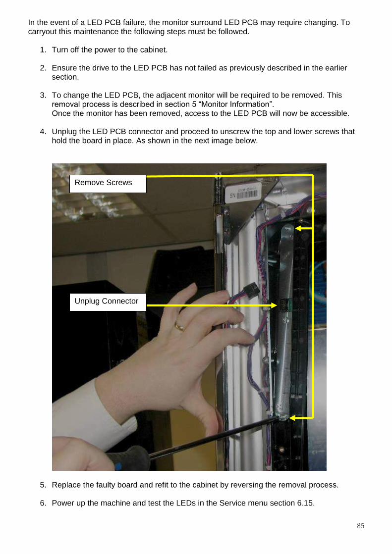
85
In the event of a LED PCB failure, the monitor surround LED PCB may require changing. To carryout this maintenance the following steps must be followed.
1. Turn off the power to the cabinet. 2. Ensure the drive to the LED PCB has not failed as previously described in the earlier
section.
3. To change the LED PCB, the adjacent monitor will be required to be removed. This removal process is described in section 5 “Monitor Information”. Once the monitor has been removed, access to the LED PCB will now be accessible.
4. Unplug the LED PCB connector and proceed to unscrew the top and lower screws that hold the board in place. As shown in the next image below.
5. Replace the faulty board and refit to the cabinet by reversing the removal process. 6. Power up the machine and test the LEDs in the Service menu section 6.15.
Unplug Connector
Remove Screws

86
10. BUTTON REPLACEMENT The Triple 7 cabinet is fitted with 4 game buttons as shown in the diagram below.
These buttons are powered from the right hand side LED driver PCB as previously described in section 9. In the event of a button failure, it is advisable to check that the driver board has not failed. This can be achieved by simply swapping the boards over. If the fault remains the problem lies with the Button itself. To replace the smaller upper buttons the following instructions must be followed.
1. Power down the machine 2. Unscrew the internal plate as shown below
Game Play Buttons

87
3. Locate the faulty button and replace.
4. Replace the internal plate, power up the machine and test the new button within the service menu “switch test” section 6.15.
Disco Button Replacement. To replace the front “Disco” button the following instructions must be followed.
1. Disconnect the power from the machine. 2. Remove the coin mechanism as described in section 6 ‘COIN MECHANISM
INFORMATION’.
3. Remove the 3 x coin mechanism mounting bracket screws as shown in the image below.
REMOVE SCREWS x3
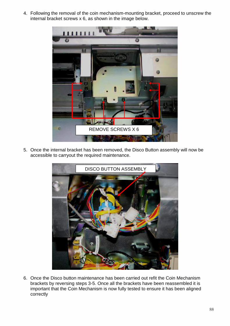
88
4. Following the removal of the coin mechanism-mounting bracket, proceed to unscrew the internal bracket screws x 6, as shown in the image below.
5. Once the internal bracket has been removed, the Disco Button assembly will now be accessible to carryout the required maintenance.
6. Once the Disco button maintenance has been carried out refit the Coin Mechanism brackets by reversing steps 3-5. Once all the brackets have been reassembled it is important that the Coin Mechanism is now fully tested to ensure it has been aligned correctly
REMOVE SCREWS X 6
DISCO BUTTON ASSEMBLY

89
11. TICKET PRINTER The ticket printer fitted within the Triple 7’s cabinet (where applicable) is the Futurlelogic Gen2 printer as shown below.
The following instructions detail the general maintenance of the printer from refilling to clearing paper jams. Ticket Refill instructions
1. It is important to follow the steps given below to ensure that the replacement stack of tickets are refilled the correctly.
2. Before placing a new paper stack it is important to fan out the tickets to prevent them
from sticking together.
3. Place the stack of tickets with the index mark facing up and towards the front of the printer as shown in the image below.
Index Mark
Feed Button
Loading Slot

90
4. Feed the ticket into the paper loading slot indicated by the left hand arrow and release it once the motor engages and the printer takes hold of the paper. Press and hold the feed button to automatically advance and align the ticket as shown in the image below and remove any excess tickets from the printer.
Clearing Paper Jam Instructions In the event of a paper jam, the following instructions must be followed.
1. Remove the stack of tickets from the printer as shown in the first image below and then open the lid by pressing the platen release lever in the direction as shown in the second image below to access the ticket path.
Loading Slot
Feed Button

91
2. If necessary access the paper path through the print mechanism by opening the mechanical release lever as indicated in the first and second images below.
3. Once the paper jam is cleared then close the mechanism release lever and then the lid.
4. The stack of tickets can now be returned to the printer and loaded in by using the Ticket Refill instructions as previously detailed.
Printer Removal. In the event of the printer requiring removal then open the middle door and then slide the printer towards the front of the machine as shown in the image below and remove. To refit the printer back into position, slide it into place and ensure that it is located fully back into position.
Pull Forwards

92
12. ADDITIONAL SECURITY
777 Security Strap Kit Fitting Instructions (KS64660). The locking bar kit consists of two pieces of metalwork, a left hand bracket that includes the security strap and a right hand side fixing plate. The kit metalwork is shown in the image below.
Section 1 Fitting Instructions
1. Switch off the machine and isolate from the mains before fitting the security strap kit. 2. Unlock the note acceptor base and then place it to one side to gain access to the right
hand side blanking plate fasteners.
3. Where there is a ticket printer fitted it will be necessary to remove the ticket printer to gain access to the left hand blanking plate.
4. Remove the left and right hand blanking plates shown in the images below by removing
the M6 nuts and washers. These can now be removed and stored in the bottom of the machine for future use.
5. Place the left hand bracket onto the side of the cabinet as shown in the first image below and secure into place with the M6 nuts and washers removed previously.

93
6. Place the right hand bracket onto the side of the cabinet as shown in the second image below and secure into place with the M6 nuts and washers removed previously.
7. Refit and lock the note acceptor back into place, power up the machine and test the note acceptor before using on site.
8. The image below shows the security strap fully assembled in position.

94
Section C TRIPLE 7’s PARTS LIST
COMPONENT PART NO
SWITCH MODE PSU 12509
19” BOTTOM MONITOR WITH TOUCH SCREEN UM60278
19” TOP MONITOR UM60279
MK6 INDUSTRIAL PC DT57499
ARDAC ELITE NOTE ACCEPTOR CC60277
SR3e ENCRYPTED COIN MECH CC71833
HOPPER ASSEMBLY (No Hoppers) UM60105
10P COMPACT HOPPER UM60267
SERIAL UNIVERSAL HOPPER UM56440
TRI-COLOUR LED PCB EA59079
LED 6 DRIVER PCB EA56417
MPU6 EC66227
START “DISCO” BUTTON QI61247
COLLECT BUTTON QI61244
HELP BUTTON QI63461
TRANSFER BUTTON QI61246
FUTURE LOGIC TICKET PRINTER GEN 2 ED61724
SECURITY STRAP KIT KS64660
TOP BOX AND INFILL POWER SUPPLY KP72934
NV11 NOTE FLOAT ACCEPTOR CI77347
VEGA NOTE ACCEPTOR CA72180

95
Tel: +44 (0)161 830 6549 Fax: +44 (0)161 343 5682 Our spares support team is staffed by a dedicated of people with over 60 years of experience in Barcrest products. They can be contacted direct on 0161 830 6549 or by email via [email protected] In terms of Spares Support we are proud of our track record of despatching 90% of all requests for spares and parts received before 3.00 p.m. on the same day. We have our own dedicated stores area which carries more than five thousand different items at any one time - covering everything from a fuse to a complete cabinet. One new initiative we are currently working on is moving our Bulletin Board Service to an Internet based solution. We have plans to develop our website further as a support medium for customers. Requests for access to the new Bulletin Board Service should be sent to the Aftersales email address. Please note that to gain access to the system you will need to already have a Spares Credit Account with Barcrest . The Barcrest spares and parts support service is available from 8.45am until 5.15pm Monday to Friday. Download a copy of our terms and conditions at http://www.barcrest .com/Barcrest_terms_cond.pdf All accounts enquires should be directed to [email protected] Tel: +44 (0)161 830 6526 Fax: +44 (0)161 830 6537
Tel: +44 (0)161 830 6549 Fax: +44 (0)161 830 6578 Our technical support team is led by Les Hunt (Email: [email protected] Tel: +44 (0)161 830 6549 Fax: +44 (0)161 830 6576.) Les and his team of experienced technical specialists can provide customers with technical help, guidance and problem resolution. Technical support staff are available to customers from 8.45 a.m. until 5.15 p.m., Monday to Friday, and our BBS (Bulletin Board Service) is available 24 hours per day, 7 days a week. We are also happy to provide training, which can be offered either at Barcrest offices or, numbers permitting, on customer premises. Among the many courses available are those covering machine servicing and unit repairs. To arrange training needs, customers can contact Les Hunt direct. (Email: [email protected])

96
Tel: +44 (0) 161 344 1000 Fax: +44 (0) 161 308 2580 In our business we regard the support we provide to customers as crucial. In that respect, we have in place a dedicated team of knowledgeable, experienced and friendly staff, able to deal promptly and efficiently with all sales related enquiries. Both in the UK and overseas, we work very closely with our carefully chosen distribution partners who also play key roles in helping us to deliver the very best customer service possible. In all respects, therefore, our single objective is the delivery of customer service excellence, and every element of feedback that we receive also forms an important part of this ongoing process.
Crown Direct, Unit 14, The Carrington Centre, Eccleston, Nr Chorley PR7 5SU, United Kingdom. Tel: +44 (0)845 838 2130 Deith Leisure, 55/56 Ladhope Vale, Galashiels, Selkirkshire, TD1 1BT United Kingdom. Tel: +44 (0)845 838 2170 RLMS Sales, Unit C1, Beeches Park, Eastern Avenue, Stretton, DE13 0BB, United Kingdom. Tel: +44 (0)845 603 6666 MDM Leisure, Hadfield Road, Leckwith Trading Estate, Cardiff, CF11 8AQ United Kingdom. Tel: +44 (0) 29 20377402