Embed Size (px)
Citation preview

GRUNDFOS PRODUCT GUIDE/INSTRUCTIONS
EZ BoostTM System withBMQE Booster Pump,Tank, and Controller Product Guide and
Installation and operating instructions
Please leave these instructions with the pump for future reference.
EZ Boost Quick Selection Guide Page 16
EZ Boost Quick Installation Guide Page 17
LEZTL01.indd 10/4/2004, 1:42 PM1
2
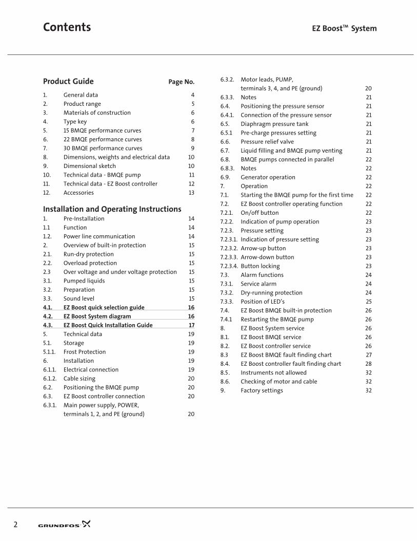
Product Guide Page No.
1. General data 4
2. Product range 5
3. Materials of construction 6
4. Type key 6
5. 15 BMQE performance curves 7
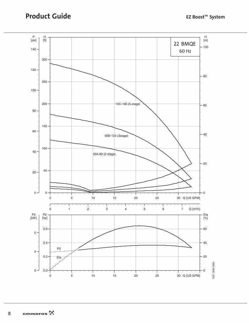
6. 22 BMQE performance curves 8
7. 30 BMQE performance curves 9
8. Dimensions, weights and electrical data 10
9. Dimensional sketch 10
10. Technical data - BMQE pump 11
11. Technical data - EZ Boost controller 12
12. Accessories 13
Installation and Operating Instructions1. Pre-Installation 14
1.1 Function 14
1.2. Power line communication 14
2. Overview of built-in protection 15
2.1. Run-dry protection 15
2.2. Overload protection 15
2.3 Over voltage and under voltage protection 15
3.1. Pumped liquids 15
3.2. Preparation 15
3.3. Sound level 15
4.1. EZ Boost quick selection guide 16
4.2. EZ Boost System diagram 16
4.3. EZ Boost Quick Installation Guide 17
5. Technical data 19
5.1. Storage 19
5.1.1. Frost Protection 19
6. Installation 19
6.1.1. Electrical connection 19
6.1.2. Cable sizing 20
6.2. Positioning the BMQE pump 20
6.3. EZ Boost controller connection 20
6.3.1. Main power supply, POWER,
terminals 1, 2, and PE (ground) 20
Contents EZ BoostTM System
6.3.2. Motor leads, PUMP,
terminals 3, 4, and PE (ground) 20
6.3.3. Notes 21
6.4. Positioning the pressure sensor 21
6.4.1. Connection of the pressure sensor 21
6.5. Diaphragm pressure tank 21
6.5.1 Pre-charge pressures setting 21
6.6. Pressure relief valve 21
6.7. Liquid filling and BMQE pump venting 21
6.8. BMQE pumps connected in parallel 22
6.8.3. Notes 22
6.9. Generator operation 22
7. Operation 22
7.1. Starting the BMQE pump for the first time 22
7.2. EZ Boost controller operating function 22
7.2.1. On/off button 22
7.2.2. Indication of pump operation 23
7.2.3. Pressure setting 23
7.2.3.1. Indication of pressure setting 23
7.2.3.2. Arrow-up button 23
7.2.3.3. Arrow-down button 23
7.2.3.4. Button locking 23
7.3. Alarm functions 24
7.3.1. Service alarm 24
7.3.2. Dry-running protection 24
7.3.3. Position of LED’s 25
7.4. EZ Boost BMQE built-in protection 26
7.4.1 Restarting the BMQE pump 26
8. EZ Boost System service 26
8.1. EZ Boost BMQE service 26
8.2. EZ Boost controller service 26
8.3 EZ Boost BMQE fault finding chart 27
8.4. EZ Boost controller fault finding chart 28
8.5. Instruments not allowed 32
8.6. Checking of motor and cable 32
9. Factory settings 32
LEZTL01.indd 10/4/2004, 1:42 PM2

Mission
GBJ - Bjerringbro, Denmark
GMU - Fresno, California GPU - Olathe, Kansas
GMX - Monterrey, Mexico GPA - Allentown, Pennsylvania GCA - Oakville, Ontario, Canada
- to successfully develop, produce, and sell high quality pumps and pumping systems worldwide, contributing to a better quality of life and healthier environment
• One of the 3 largest pump companies in the world
• World headquarters in Denmark
• North American headquarters in Kansas City - Manufacturing in Fresno, California
• 60 companies in 40 countries
• More than 10 million pumps produced annually worldwide
• North American companies operating in USA, Canada and Mexico
• Continuous reinvestment in growth and development enables the company to
BE responsible, THINK ahead, and INNOVATE
5

4
EZ BOOST SYSTEM
IntroductionThere are many applications within water supply where it is necessary to increase the system pressure. The Grundfos EZ Boost system is the optimum solution for applications requiring:• Sealless pumps
• Quiet operation and/or
• Maintenance-free operation.
The EZ Boost system offers the following features:
• Dry-running protection
• High efficiency of pump and motor
• Excellent wear resistance
• Soft starter
• Over voltage and under voltage protection
• Overload protection
• Over temperature protection.
• Variable speed
• Electronic control and communication.
Applications• Pressure boosting.
• Water treatment.
Pumped liquidsThin, non-explosive liquids not containing abrasive par-ticles or fibers. The liquid must not be able to attack the pump materials chemically or mechanically.
Should the density and/or viscosity of the pumped liquid exceed the density and/or viscosity of water, please con-tact Grundfos.
BMQE PumpThe pumps used for The Grundfos EZ Boost system are modified SQE submersible pumps. The EZ Boost BMQE pump is an SQE pump with an MSE 3 motor. Pump and motor are centered in the 3” stainless steel sleeve.
BMQE pumps are suitable for both continuous and intermittent operation for a variety of pressure boosting applications.
BMQE MotorThe MSE 3 motors are based on state-of-the-art technology within permanent magnets (PM motor), which accounts for the high motor efficiencies. In addition, the motors have a built-in electronic unit with a frequency converter for variable frequency and soft starting.
Product Guide EZ BoostTM System
The MSE 3 motors features high efficiency within a wide load range. The high and flat efficiency curve of the PM motor enables the same motor to cover a wide power range as opposed to conventional AC motors. For BMQE pumps, this means fewer motor variants.
EZ Boost ControllerThe BMQE pump features variable speed which is offered through frequency control via the EZ Boost controller. As a consequence, the pump can be set to operate in any duty point in the range between the minimum and maximum performance curves of the pump. Each BMQE pump must be connected to its own EZ Boost controller.
It is also possible to operate the BMQE without an EZ Boost controller, though the features offered will be fewer.
Operating conditionsFlow: Max. 39 US GPM (8.9 m3/h)
Head: Max. 300 ft (91.4 m)
Temperature: Max. 95°F (35°C)
Operating pressure: Max. 145 PSI (10 bar)
Inlet pressure: Min. 8 PSI (0.55 bar)
Sound-pressure level: The sound pressure level of the BMQE is lower than 74 db[A] at a distance of 3 feet (1 meter).
It is recommended by Grundfos that the pump be installed with sound and vibration dampening equipment such as flexible piping adapters and anti-vibration mounting. The pump should not be mounted in or adjacent to living quarters. The pump can also be wrapped with sound- proofing insulation to reduce noise (see page 16, EZ Boost System Diagram).
BMQE Pump Sectional Drawing
Pos.1. Sleeve 5. SQE pump2. Discharge connection 6. Cable entry3. Suction connection 7. Centering device4. MSE 3 motor 8. Air vent screw
6
2
5 4 7
31
8
LEZTL01.indd 10/4/2004, 1:42 PM4

Performance range, 60 Hz
Product range
Range BMQE 15 BMQE 22 BMQE 30
Nominal flow rate [US GPM (m3/h)] 15 (3.4) 22 (5.0) 30 (6.8)
Temperature range +32 to +95°F (0 to +35°C)
Maximum working pressure [PSI (bar)] 145 (10)
Maximum efficiency [%] 57 62 60
Flow range [US GPM (m3/h)] 0 to 19 (4.3) 0 to 33 (7.5) 0 to 39 (8.8)
Maximum pump pressure [ft (m)/PSI] 300 (91.4)/130 290(88.4)/125 208(63.4)/90
Pipe connection 1.25” NPT inlet / 1” NPT discharge
Product Guide EZ BoostTM System
5
0 5 10 15 20 25 30 35 Q [US GPM]
0
40
80
120
160
200
240
280
[ft]H
0
20
40
60
80
100
120
P[psi]
0 1 2 3 4 5 6 7 8 9 Q [m³/h]
0
20
40
60
80
H[m]
30 BMQE 05B-90
22 BMQE 05B-120
15 BMQE 05A-110
15 BMQE 07B-180
22 BMQE 05A-80
22 BMQE 10C-190
30 BMQE 10C-130
TK
0131
0133
04
LEZTL01.indd 10/4/2004, 1:42 PM5
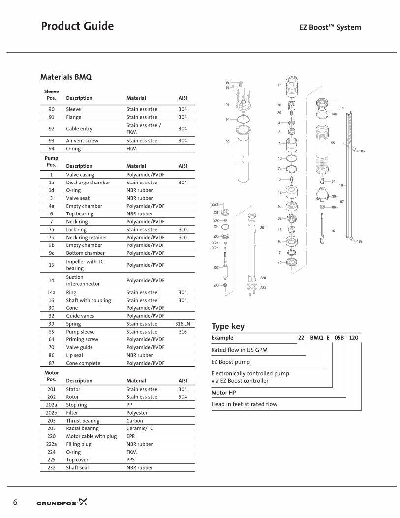
Materials BMQ
SleevePos. Description Material AISI
90 Sleeve Stainless steel 304
91 Flange Stainless steel 304
92 Cable entryStainless steel/FKM
304
93 Air vent screw Stainless steel 304
94 O-ring FKM
PumpPos. Description Material AISI
1 Valve casing Polyamide/PVDF
1a Discharge chamber Stainless steel 304
1d O-ring NBR rubber
3 Valve seat NBR rubber
4a Empty chamber Polyamide/PVDF
6 Top bearing NBR rubber
7 Neck ring Polyamide/PVDF
7a Lock ring Stainless steel 310
7b Neck ring retainer Polyamide/PVDF 310
9b Empty chamber Polyamide/PVDF
9c Bottom chamber Polyamide/PVDF
13Impeller with TC bearing
Polyamide/PVDF
14Suctioninterconnector
Polyamide/PVDF
14a Ring Stainless steel 304
16 Shaft with coupling Stainless steel 304
30 Cone Polyamide/PVDF
32 Guide vanes Polyamide/PVDF
39 Spring Stainless steel 316 LN
55 Pump sleeve Stainless steel 316
64 Priming screw Polyamide/PVDF
70 Valve guide Polyamide/PVDF
86 Lip seal NBR rubber
87 Cone complete Polyamide/PVDF
MotorPos. Description Material AISI
201 Stator Stainless steel 304
202 Rotor Stainless steel 304
202a Stop ring PP
202b Filter Polyester
203 Thrust bearing Carbon
205 Radial bearing Ceramic/TC
220 Motor cable with plug EPR
222a Filling plug NBR rubber
224 O-ring FKM
225 Top cover PPS
232 Shaft seal NBR rubber
Type keyExample 22 BMQ E 05B 120
Rated flow in US GPM
EZ Boost pump
Electronically controlled pumpvia EZ Boost controller
Motor HP
Head in feet at rated flow
Product Guide EZ BoostTM System
1d
7a
1
70
2
39
3
1a
55
16
30
8687
6418
18b
18a
6
4a
9b
32
13
9c
7
14
14a
7b
9293
91
94
90
202a
202
202b
222a
232
203
224
205
225
201
220
233
6
LEZTL01.indd 10/4/2004, 1:42 PM6

Product Guide EZ BoostTM System
7
0 2 4 6 8 10 12 14 16 18 Q [US GPM]
0
50
100
150
200
250
300
[ft]H
0
20
40
60
80
100
120
140
P[psi]
0
20
40
60
80
100
H[m]
0.0 0.5 1.0 1.5 2.0 2.5 3.0 3.5 4.0 4.5 Q [m³/h]
15 BMQE60 Hz
07B-180 (5-stage)
05A-110 (3-stage)
0 2 4 6 8 10 12 14 16 18 Q [US GPM]
0.0
0.1
0.2
0.3
[hp]P2
0
20
40
60
[%]Eta
0.0
0.1
0.2
P2[kW]
P2
Eta
TK
0130
9833
04
LEZTL01.indd 10/4/2004, 1:42 PM7
Product Guide EZ BoostTM System
8
0 5 10 15 20 25 30 Q [US GPM]
0
50
100
150
200
250
300
[ft]H
0
20
40
60
80
100
120
140
P[psi]
0
20
40
60
80
100
H[m]
0 1 2 3 4 5 6 7 Q [m³/h]
05A-80 (2-stage)
05B-120 (3stage)
10C-190 (5-stage)
0 5 10 15 20 25 30 Q [US GPM]
0.0
0.2
0.4
0.6
[hp]P2
0
20
40
60
[%]Eta
0
0
0
P2[kW]
P2
Eta
TK
0130
9933
04
LEZTL01.indd 10/4/2004, 1:42 PM8

9
Product Guide EZ BoostTM System
0 5 10 15 20 25 30 35 Q [US GPM]
0
20
40
60
80
100
120
140
160
180
200
220
[ft]H
0
10
20
30
40
50
60
70
80
90
P[psi]
0 1 2 3 4 5 6 7 8 9 Q [m³/h]
0
10
20
30
40
50
60
70
H[m]
05B-90 (2-stage)
10C-130 (3-stage)
0 5 10 15 20 25 30 35 Q [US GPM]
0.0
0.2
0.4
0.6
[hp]P2
0
20
40
60
[%]Eta
0
0
0
P2[kW]
P2
Eta
TK
0131
0033
04
LEZTL01.indd 10/4/2004, 1:42 PM9

Product Guide EZ BoostTM System
10
ModelMaterialnumber
Max. motor output[P2] Rated
Voltage
Ratedcurrent
[A]
Locked rotorcurrent
[A]
Shipping weight[lb (kg)]
Shippingvolume
[ft3 (m3)]hp kW
15 BMQE 05A-110 91128524 0.845 0.63 110-115 9.2 11.1 26 (11.8)
0.9 (0.025)
22 BMQE 05A-80 91128527 0.845 0.63 110-115 7.8 11.1 26 (11.8)
15 BMQE 05A-110 91128525 0.845 0.63 200-240 4.6 5.0 26 (11.8)
15 BMQE 07B-180 91128526 1.408 1.05 200-240 7.1 8.0 29 (13.2)
22 BMQE 05A-80 91128528 0.845 0.63 200-240 3.9 5.0 26 (11.8)
22 BMQE 05B-120 91128529 1.408 1.05 200-240 5.6 8.0 29 (13.2)
22 BMQE 10C-190 91128530 2.320 1.73 200-240 9.9 11.1 31 (14.1)
30 BMQE 05B-90 91128531 1.408 1.05 200-240 6.0 8.0 31 (14.1)
30 BMQE 10C-130 91128533 2.320 1.73 200-240 9.5 11.1 31 (14.1)
Weights and electrical data
43.3"/1100
Cable entry
Air ventscrew
0.8"/20.5
ø4.
6"/1
16
ø3.
5"/8
8.9
1.25" NPT
1.0" NPT
Dimensional sketch [in/mm]
LEZTL01.indd 10/4/2004, 1:42 PM10
11
Product Guide EZ BoostTM System
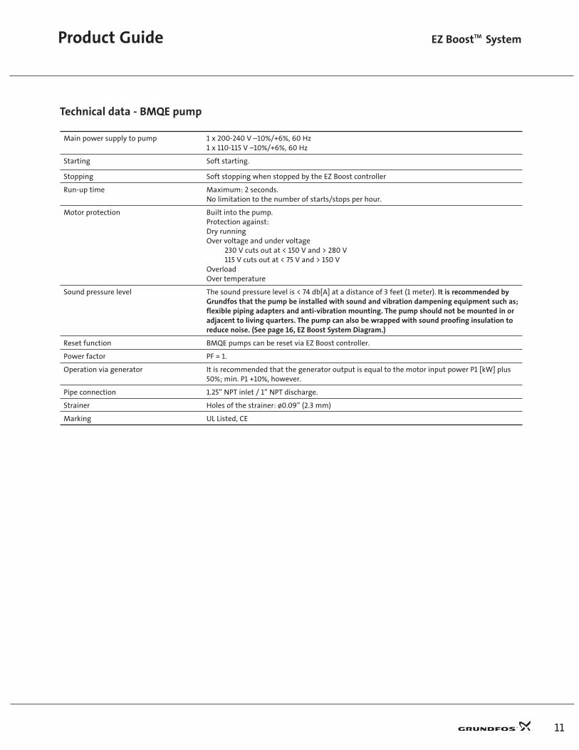
Main power supply to pump 1 x 200-240 V –10%/+6%, 60 Hz1 x 110-115 V –10%/+6%, 60 Hz
Starting Soft starting.
Stopping Soft stopping when stopped by the EZ Boost controller
Run-up time Maximum: 2 seconds.No limitation to the number of starts/stops per hour.
Motor protection Built into the pump.Protection against:Dry runningOver voltage and under voltage 230 V cuts out at < 150 V and > 280 V 115 V cuts out at < 75 V and > 150 VOverloadOver temperature
Sound pressure level The sound pressure level is < 74 db[A] at a distance of 3 feet (1 meter). It is recommended by Grundfos that the pump be installed with sound and vibration dampening equipment such as; flexible piping adapters and anti-vibration mounting. The pump should not be mounted in or adjacent to living quarters. The pump can also be wrapped with sound proofing insulation to reduce noise. (See page 16, EZ Boost System Diagram.)
Reset function BMQE pumps can be reset via EZ Boost controller.
Power factor PF = 1.
Operation via generator It is recommended that the generator output is equal to the motor input power P1 [kW] plus 50%; min. P1 +10%, however.
Pipe connection 1.25” NPT inlet / 1” NPT discharge.
Strainer Holes of the strainer: ø0.09” (2.3 mm)
Marking UL Listed, CE
Technical data - BMQE pump
LEZTL01.indd 10/4/2004, 1:42 PM11

Product Guide EZ BoostTM System
12
EZ Boost ControllerThe EZ Boost controller is a control and communication unit especially developed for the BMQE booster pumps in constant pressure applications.
The EZ Boost controller provides:
• Full control of the BMQE pumps
• Two-way communication with the BMQE pumps
• Possibility of adjusting the pressure
• Alarm indication (LED) when service is needed
• The possibility of starting, stopping and resetting the pump simply by means of a push-button
The EZ Boost controller communicates with the pump via power line communication, meaning that no extra cables are required between the EZ Boost controller and the BMQE pump.
The EZ Boost controller features the following indications (see drawing below):1. Flow indicator
2. System pressure setting
3. System ON/OFF
4. Button lock indicator
5. Dry-running indicator
6. Service needed in case of:
– No contact to pump – Over voltage – Under voltage – Speed reduction – Over temperature – Overload – Sensor defective
The EZ Boost controller incorporates external signal input for pressure sensor.
Voltage 1 x 100-240 V –10%/+6%, 60 Hz
Powerconsumption
5 W
Currentconsumption
Maximum 130 mA
Enclosure class NEMA 3R (IP 55)
Ambienttemperature
In operation: -22 to +122°F (-30 to +50°C)during storage: -22 to +140°F (-30 to +60°C)
Relativeair humidity
95%
Pump cableMaximum length between EZ Boost controller and pump: 650 ft (198 m).
Back-up fuse Maximum: 16 A
Marking UL Listed, CE
Load Max. 100 mA
2 3
4
1
5
6
Power supply entry
Submersible drop cable entry
Pressure sensorentry
9 3/15 in. (232 mm) 4 1/2 in. (114 mm)
7 11
/16
in. (
195
mm
)
LEZTL01.indd 10/4/2004, 1:42 PM12

13
Product Guide EZ BoostTM System
Accessories
EZ Boost constant pressure kit
Description Rating Material number
EZ Boost controller and pressure sensor 40 to 100 PSI setting range 91128636
EZ Boost controller
Description Rating Material number
EZ Boost controller 40 to 100 PSI setting range 91121987
Sensor
Description Rating Material number
Pressure sensor kit for EZ Boost controller 0 to 120 PSI, 1/2” NPT 96437852
Diaphragm tank
Duty rangePre-charge pressure: 40 PSIMax. operating pressure: 150 PSIMax. liquid temperature: 200°F
MaterialsLiner: PolypropyleneConnection: Lead-free brassTank: Stainless steel, AISI 304
DescriptionG
connectionD
[in (mm)]H
[in (mm)]Weight
[lbs (kg)]Materialnumber
Diaphragm tank,2 gallon
3/4” NPT 8 (203) 12.63 (321) 5 (2.3) 91121984
G
D
H
LEZTL01.indd 10/4/2004, 1:42 PM13

Instructions EZ BoostTM System
14
PRE-INSTALLATIONBefore beginning installation procedures, these installation and operating instructions should be studied carefully. The installation and operation should also be in accordance with local regulations and accepted codes of good practice.
The sound pressure level of the BMQE is <74 db[A] at a distance of 3 feet (1 meter). It is recommended by Grundfos that the pump be installed with sound and vibration dampening equipment such as; flexible piping adapters and anti-vibration mounting. The pump should not be mounted in or adjacent to living quarters. The pump can also be wrapped with sound proofing insulation to reduce noise. (See page 16, EZ Boost System Diagram.)
1. A guide to the EZ Boost SystemThe EZ Boost Constant Pressure System automatically balances water surges and equalizes flow and pressure according to consumption. In other words, the system maintains a constant water pressure in spite of varying water consumption. The pressure is registered by means of the pressure sensor and transmitted to the controller. The controller adjusts the EZ Boost BMQE pump performance accordingly. The EZ Boost Constant Pressure System features:
• Quick and easy installation: ready-to-use system requiring minimum space
• High user convenience: constant pressure regardless of water consumption
• Easily adjustable pressure level: push button control
• Continuous control and monitoring of pump operation
• Integrated dry-running protection
• Integrated overload protection
• Integrated protection against over voltage and under voltage
• Soft start system
1.1 FunctionWhen a tap is opened, the pressure in the tank will start to drop. The system maintains a constant pressure within the maximum pump performance in spite of varying water consumption.
The pressure is registered by means of the pressure sensor, which transmits a signal to the controller. The controller adjusts the pump performance accordingly to maintain constant pressure by changing the pump speed.
At low flow the pressure will drop slowly. When the
pressure in the tank is 7 PSI below the setpoint, the pump will start. When the pressure is 7 PSI above the setpoint, the pump will stop.
Even though the EZ Boost controller is controlling the pressure within ±3 PSI, larger pressure variations may occur in the system. If the consumption is suddenly changed, e.g. if a tap is opened, the water must start flowing before the pressure can be made constant again. Such dynamic variations depend on the pipe work, but, typically, they will lie between 7 and 14 PSI. If the desired consumption is higher than the quantity the pump is able to deliver at the desired pressure, the pressure follows the pump curve as illustrated in the far right of fig. 1.
Fig. 1
At large flow rates, the pressure will drop quickly and the pump will start immediately and maintain constant pressure. When the system is running, the EZ Boost controller makes small adjustments to the pressure to detect whether there is consumption. If there is none, the pump will simply refill the tank and stop after a few seconds.
1.2 Power line communicationThe communication between the EZ Boost controller and the EZ Boost BMQE pump is via the power supply cable. This communication principle is known as power line communication. Using this principle means that no additional cables to the pump are required. The communication of data is effected by means of a high-frequency signal transmitted to the power supply cable. In situations where multiple EZ Boost BMQE pump power cables are run parallel in wiring trays or conduit and less than 12 inches apart, the possibility for undesired communication between units exists. When this occurs, intermittent or continuous NO CONTACT is typically seen. Other unexpected errors may also be seen.
There are two ways to eliminate the possibility of cross communication:
Pressure
Flow
A
Stop+7 PSI
Start -7 PSI
Controlling ±3 PSI
Dynamic variations ±7 PSI
GPM0.8
A = Pressure setting
LEZTL01.indd 10/4/2004, 1:42 PM14

15
Instructions EZ BoostTM System
1. Physical separation of the cables – maintain a minimum of 12 inches between pump power cables, and never place more than one cable in a conduit.
2. Use shielded cable – the use of shielded cable prevents cross communication between parallel cables and allows sharing of conduit and cable trays. Tie the cable shield to ground only at the EZ Boost controller panel.
Suitable cables:
Manufacturer Part number Gage
Anixter 2A-1403S 14
Anixter 2A-1203S 12
Anixter 2A-1003S 10
Anixter 800-321-1486
2. Overview of built-in protection
2.1. Run-dry protectionThe EZ Boost BMQE pumps are protected against dry-running. In case of dry-run, the BMQE will stop after 30 seconds thus preventing a burnout of the motor. After a dry-running alarm, the pump restarts automatically after 5 min.
2.2. Overload protectionExposure of the BMQE pump to heavy load causes the current consumption to rise. The motor will automatically compensate for this by reducing the speed. If the speed drops to 30% of the rated speed, the motor will be cut out. If the rotor is being prevented from rotating this will automatically be detected and the power supply cutout. Consequently, no extra motor protection is required.
2.3. Over voltage and under voltage protectionOver voltage and under voltage may occur if the voltage supply is unstable. The integrated protection of the BMQE motor protects the motor if the voltage falls outside the permissible voltage range. With a rated voltage of 200 - 240 V, 60 Hz, the pump will be cut out if voltage falls below 150 V or rises above 280 V. With a rated voltage of 110 - 115 V, 60 Hz, the pump will be cut out if voltage falls below 75 V or rises above 150 V. The motor is automatically cut in when the voltage is again within the permissible voltage range. Therefore, no extra voltage protection relay is required.
3.1. Pumped liquidsThe EZ Boost BMQE must not be used for the transfer of flammable liquids such as diesel oil, petrol or similar liquids. The EZ Boost BMQE is designed for pumping thin, clean, non-aggressive, non-explosive liquids, not containing solid particles or fibers. The EZ Boost BMQE is suitable for pressure boosting clean, cool, potable water. The liquid must notattack the pump materials chemically or mechanically.
Liquid temperature: The temperature of the pumped liquid must not exceed +95°F (+35°C).
Delivery and transportationGRUNDFOS EZ Boost System components are supplied from the factory in proper packaging in which they should remain until they are to be installed. The components are ready for installation.
3.2. PreparationBefore installation, the following checks should be made:
• Pump type: Check that the pump type stated on the name-plate fitted to the module sleeve corresponds to order.
• Electricity supply: The motor voltage and frequency details stated on the nameplate should be compared with the actual electricity supply available.
3.3. Sound pressure levelThe sound pressure level of the BMQE is <74 db[A] at a distance of 3 feet (1 meter). It is recommended by Grundfos that the pump be installed with sound and vibration dampening equipment such as; flexible piping adapters and anti-vibration mounting. The pump should not be mounted in or adjacent to living quarters. The pump can also be wrapped with sound proofing insulation to reduce noise.
LEZTL01.indd 10/4/2004, 1:42 PM15

Instructions EZ BoostTM System
16
4. EZ Boost Quick Guide4.1 . EZ Boost Quick Selection GuideExample:1. The maximum demand is 15 GPM (3.4 m3/h).
2. The pressure required is 70 PSI system pressure at the taps in the building.
3. The normal minimum inlet pressure (e.g. city pressure) is 20 PSI.
4. The additional boost required is 50 PSI at 15 GPM (3.4 m3/h).
5. Select a 15 BMQE 05A-110.
4.2. EZ Boost System DiagramThe EZ Boost Constant Pressure System should consist of:
Pos.1. EZ Boost BMQE pump
2. EZ Boost controller
3. Diaphragm tank (recommended size 2 U.S. gallons (8 liter)/130 psi)
2
3
4
1 5 66
EZ Boost Quick Select Guide
3. EZ Boost Quick Select Guide (below)
Example:1. The maximum demand is 15 GPM (3.4 m3/h).
2. The pressure required is 70 PSI system pressure at the taps in the building.
3. The normal minimum inlet pressure (e.g. city pressure) is 20 PSI.
4. Select a 15 BMQE 05A-110.
Additional (boost) pressure required
5 10 15 20 25 30 35 39Flow required in gallons per minute (GPM)
in PSI908070605040302010
15 BMQE 05A-11015 BMQE 05A-110
30 BMQE 05B-9030 BMQE 05B-90
30 BMQE 10C-13030 BMQE 10C-130
22 BMQE 10C-19022 BMQE 10C-190
22 BMQE 05B-12022 BMQE 05B-120
22 BMQE 05A-8022 BMQE 05A-80
15 BMQE 07B-18015 BMQE 07B-180
4. Pressure sensor
5. Mounting brackets
6. Flex connector
LEZTL01.indd 10/4/2004, 1:42 PM16

17
Instructions EZ BoostTM System
4.3. EZ Boost Quick Installation GuideFOR MORE DETAILED INSTALLATION INSTRUCTIONS, PLEASE GO TO SECTION 6.
1. Install BMQE pump.
2. Install EZ Boost controller.
PE
PE
POWER PUMP1 2 3 4
+24V
ING
ND
SEN
SOR
1 2 3 4
2. Install EZ Boost controller.
3. Install diaphragm tank.3. Install diaphragm tank.
4. Install pressure sensor.4. Install pressure sensor.
5. Connect incoming power, BMQE pump, and pressure sensor to EZ Boost controller.
PE
PE
POWER PUMP1 2 3 4
+24V
ING
ND
SEN
SOR
5. Connect incoming power, BMQE pump and pressure sensor to EZ Boost controller.
1 2 3 4
6. Close EZ Boost controller cover.7. Switch on main power.
6. Close EZ Boost controller cover7. Switch on main power.
Red lightis on
1. Install BMQE pump.
LEZTL01.indd 10/4/2004, 1:42 PM17

Quick Guide EZ BoostTM System
18
8. Set EZ Boost controller discharge PSI and verify diaphragm pre-charge pressure.8. Set EZ Boost controller discharge PSI and verify diagphragm pre-charge pressure.
Diaphragm TankPre-Charge
PSI PSI
9. Switch on EZ Boost controller.
9. Switch on power.
Green light is on
10. Verify that BMQE pump is operating.10. Verify that BMQE pump is operating.
Consult Troubleshooting
Section
11. Verify that EZ Boost controller is operating.
11. Verify EZ Boost controller is operating.
These lights are on
These lights are on
12. Optional: Lock the buttons.
12. Optional: Lock the buttons.
5 seconds
LEZTL01.indd 10/4/2004, 1:42 PM18

19
Quick Guide EZ BoostTM System
5. Technical dataSupply voltage: 1 x 200-240 V –10%/+6%, 60 Hz 1 x 110-115 V –10%/+6%, 60 Hz
Fluid temperature: Max. 95°F (35°C)
Starting current: The motor starting current is equal to the highest value stated on the EZ Boost BMQE nameplate.
Power factor: PF = 1.0
Motor cable: • 2-wire w/ground, 12 AWG Teflon
• B: Black (Line, Neutral).
• G: Green (Ground).
EZ Boost BMQE inlet/discharge size: 1.25” NPT inlet / 1” NPT discharge.
EZ Boost BMQEmaximum net weights: 31 lbs. (14.1 kg)
5.1. StorageEZ Boost BMQEstorage temperature: +32°F to +140°F (0°C to +60°C).
EZ Boost controllerstorage temperature: -22°F to +140°F (-30°C to +60°C).
5.2. Frost protectionIf the BMQE has to be stored after use, it must be stored in a frost-free location or it must be ensured that the motor liquid is frost-proof. The BMQE is shipped from the factory with motor fluid that protects the motor down to -4°F(-20°C). The motor must not be stored without being filled with motor liquid.
6. Installation6.1.1 Electrical connection
The electrical connection should be carried out by an authorized electrician in accordance with local regulations.
Before starting work on the EZ Boost controller or BMQE, make sure that the electricity supply has been switched off and that it cannot be accidentally switched on. The BMQE must be grounded. The EZ Boost controller must be connected in accordance with the local rules and regulations.
IMPORTANT: The on/off button on the EZ Boost controller must not be used as a safety switch when installing and servicing the pump.
Rain-tight or wet location hubs that comply with the requirements in the standard for Fittings for Conduit and Outlet Boxes, UL514B, are to be used. Suitable devices for EZ Boost controller are rated with enclosure type 3, 3R, 3S, 4, 4X, 6 or 6P.
The supply voltage and frequency are marked on the nameplate. Make sure that the EZ Boost controller and BMQE pump are suitable for the electricity supply on which they will be used.
The current consumption can only be measured by means of a true RMS instrument. If other instruments are used, the value measured will differ from the actual value.
All EZ Boost BMQE pumps can be connected to EZ Boost controllers. Each BMQE pump must be connected to its own EZ Boost controller.
CAUTION!The EZ Boost BMQE must never be connected to a capacitor or to another type of control box than EZ Boost controller.
The EZ Boost BMQE must never be connected to an external frequency converter.
Motor protection: The EZ Boost BMQE incorporates thermal overload protection and requires no additional motor protection.
Connection of motor: The EZ Boost BMQE incorporates a starter device and can therefore be connected directly to the main power supply.
WARNING! Reduced risk of electric shock during operation of this EZ Boost system requires the provision of acceptable grounding. If the means of connection to the supply connected box is other than grounded metal conduit, ground the pump back to the service by connecting a copper conductor, at least the size of the circuit supplying the pump.
LEZTL01.indd 10/6/2004, 3:37 PM19

In situations where multiple EZ Boost power cables are run parallel in wiring trays or conduit and less than 12 inches apart, the possibility for undesired communication between units exists. When this occurs, intermittent or continuous NO CONTACT is typically seen. Other unexpected errors may also be seen. Refer to section 1.2 and 8.4, #5 for further instructions.
6.2. Positioning the BMQE pumpThe GRUNDFOS EZ Boost BMQE pump is supplied with a built-in non-return valve. An arrow on the BMQE sleeve shows the direction of liquid flow through the pump, fig. 3.
The BMQE is suitable for both vertical and horizontal installation, however, the discharge port should never fall below the horizontal plane, see fig. 4.
The BMQE must be installed with the air relief vent in the 12 o’clock position when installed horizontally and when installed in the vertical position, the air vent must be at the top of the unit.
Fig. 3
Instructions EZ BoostTM System
20
6.1.2. Cable sizing* Single-phase 60 HZ maximum cable length motor service to entrance
Motor rating Copper wire size (AWG)
Volts HP 14 12 10
Maximum cable length [ft/m]
115 0.50 100/30.5 160/48.8 250/76.2
230 0.50 400/121.9 650/198.1 650/198.1
0.75 300/91.4 480/146.3 650/198.1
1.0 250/76.2 400/121.9 630/192
* The maximum cable length with one EZ Boost Controller is 650’ and the maximum wire size is 10 AWG.
Allowed
Not allowed
Fig. 4
6.3. EZ Boost controller connectionThe EZ Boost controller has two terminal blocks:• Terminals 1 to 4.
• Terminals 5 to 7.
Furthermore, the EZ Boost controller is equipped with two screw terminals for the ground leads.
6.3.1. Main power supply, POWER, terminals 1, 2 and PE (ground):Connect terminals 1 and 2 to the line and neutral leads of the main supply. Each terminal can be connected to any of the two leads.
NOTE: Circuit breaker: Maximum 16 A.
IMPORTANT: The main power supply cables must not be connected to terminals 3 and 4 (PUMP).
6.3.2. Motor leads, PUMP, terminals 3, 4 and PE (ground):Connect terminals 3 and 4 to the line and neutral leads of the pump. Each terminal can be connected to any of the two leads.
LEZTL01.indd 10/6/2004, 4:28 PM20

21
Instructions EZ BoostTM System
POWER
PE
PUMP
PE
LN
Bro
wn
Bla
ck
4
1
3
2
SENSOR5 6 7
+24V
IN GND
L1L N
L2For 230V
6.3.3. NOTES: Connect one PE terminal to the green ground lead from the pump and one to the ground lead from the main power supply. Each PE terminal must be connected to its own ground lead.
Maximum wire size of the cables to be connected to EZ Boost controller is 10 AWG.
6.4. Positioning the pressure sensorPressure losses often cause inconvenience to the user. The EZ Boost controller keeps the pressure constant in the place where the pressure sensor is positioned (see EZ Boost System Diagram on page 16). In the diagram tap 1 is placed close to the pressure sensor. Therefore, the pressure will be kept nearly constant at tap 1, as the friction loss is small. At the shower and tap 2, the friction loss is greater. This, of course, depends on the piping. Therefore, it is recommended that the pressure sensor be positioned as close to the places of consumption as possible. The maximum shielded cable length for the sensor must not exceed 1600 feet.
6.4.1 Connection of the pressure sensorSENSOR, terminals 5, 6 and 7:Terminals 5, 6 and 7 (SENSOR) are used for the pressure sensor.
Pos. Description
1 Standard pressure sensor.+ 24 VDC, brown lead, terminal 5.
2 Standard pressure sensor. Input signal, black lead, terminal 6.
3 Standard pressure sensor. Braid, terminal 7.
Sensor signals:The pressure sensor to be conected provides a 4-20 mA signal (factory setting).
6.5. Diaphragm Pressure TankThe EZ Boost controller is designed to work with a 2 gal. diaphragm tank. Install a diaphragm tank to insure that the BMQE will shut off at zero flow. The diaphragm tank must be installed at some point between the BMQE pump and the pressure sensor.
6.5.1 Pre-charge Pressure SettingThe pre-charge pressure of the diaphragm tank must be set to 70% of the pressure setting in order to use the tank to the limit of its capacity.
Use the values in the following table. Pre-charge pressure is measured with 0 PSI in the pipeline:
Setting (PSI) Pre-charge pressure (PSI)
40 28
50 35
60 42
70 49
80 56
90 63
100 70
Note: If the pre-charge pressure is higher than the pressure setting, the system will have difficulty controlling the pressure.
If the user wants to adjust the pressure without changing the pre-charge pressure of the diaphragm tank, the pre-charge pressure must be equal to the lowest pressure setting used. Failure to follow this instruction will increase pressure fluctuations.
6.6. Pressure Relief ValveIn order to provide protection against the possibility of over pressurization, a pressure relieve valve may be installed down stream of the BMQE. If a relief valve is installed, it is recommended that its discharge be plumbed into an appropriate drainage point.
6.7. Liquid filling and BMQE pump ventingThe BMQE is filled with water through the suction port by the water in the piping system.
1. The BMQE should be installed with the air relief vent in the 12 o’clock position when installed horizontally and when installed in the vertical position the air vent must be at the top of the unit.
2. Loosen the air vent screw in the BMQE pump.
3. Fill the BMQE with water until it starts running out of the vent hole.
4. Tighten the air vent screw.
LEZTL01.indd 10/4/2004, 1:42 PM21

Instructions EZ BoostTM System
22
1
2
Air escape valve
Diaphragm tank
EZ Boost controller
Isolation valve
Pressure gauge
Green indicator light
Red indicator light
6.8. BMQE pumps connected in parallel
6.8.1. When connecting BMQE pumps in parallel as shown in fig. 5, a separate EZ Boost controller must be used on each BMQE. Set the pressure on one BMQE 10 PSI lower than the other.
6.8.2. For BMQE pumps connected in parallel, mounted above each other, it is recommended to connect the pipes as shown in fig. 5. This layout ensures that the BMQE pumps are filled with water before starting.
Fig. 5 Booster unit with two BMQE pumps connected in parallel, mounted above each other.
6.8.3. Notes:• All BMQE modules are supplied with a non-return valve.
• BMQE modules connected in parallel may also be installed vertically.
• As venting problems may arise in such installations, it is advisable to install suitable air vent devices.
• The BMQE should be positioned with the discharge and air vent at the top when installed vertically.
6.9. Generator OperationPower may be supplied to BMQE pumps by an adequately sized generator. The generator must be sized 50% above the pumps P1 (input power) values. See following chart.
Motor HP Minimumgenerator
size
Recommended generator
output (watts)
0.33 to 0.50 A 1100 1500
0.50 to 0.75 B 1700 2300
1.0 to 1.5 B 2000 3500
7. Operation
7.1. Starting the BMQE Pump for the First TimeWhen the BMQE has been connected correctly, it should be started with the discharge valve closed approximately one-third. Due to the soft start feature, the pump takes approximately 2 seconds to develop full pressure.
Check that the actual inlet pressure is equal to or greater than the previously estimated inlet pressure.
When not being used, all modules should be filled with water as all internal bearings are water lubricated.
If the BMQE is taken out of operation for a long period, the BMQE should be flushed through with clean water. The modules are then left with clean water until they are to be used again.
7.2. EZ Boost Controller Operating Functions
7.2.1 On/off buttonFig.6 shows the on/off button of the EZ Boost controller.
Fig. 6
LEZTL01.indd 10/4/2004, 1:42 PM22

23
Instructions EZ BoostTM System
The green and red indicator lights in the on/off button indicate pump operating condition as follows:
Indication Description
Green indicator light permanently on.
The system is operational.
Green indicator light off. The system is not operational.
Red indicator light permanently on.
Pump has been stopped by means of the On/Off button.*
*If the on/off button has been used to stop the pump, this button must also be used for restarting.
Any alarm indication can be reset by pressing the on/off button.
If the on/off button is pressed for more than 5 seconds, the pump is started, irrespective of any active fault/alarm indications and sensor signals.
When the on/off button is released, the pump will stop, if the alarm still exists.
IMPORTANT:Setting this button to the OFF position DOES NOT remove power from the pump. Before servicing the pump, remove power at the service breaker.
7.2.2. Indication of pump operationOn the graphical illustration on the EZ Boost controller face, the pipe shows run lights when the pump is operating. When the pump is not operating, none of the flow indicator lights are on, see fig. 7.
Fig. 7
7.2.3 Pressure settingThe two arrow buttons on the EZ Boost controller front are used for the pressure setting, see fig. 8.
Fig. 8
7.2.3.1 Indication of pressure setting:The system pressure set is indicated by a yellow indicator light, which is permanently on. Setting range: 40-100 PSI.
7.2.3.2 Arrow-up button:When this button is pressed, the system pressure setting is increased in steps of 10 PSI.
7.2.3.3 Arrow-down button:When this button is pressed, the system pressure setting is decreased in steps of 10 PSI.
7.2.3.4. Button lockingThe buttons on the EZ Boost controller can be locked/unlocked by pressing the two arrow buttons simultaneously for 5 seconds.
NOTE: When the arrow buttons are used for locking, take care not to inadvertently change the pressure setting. When the buttons are locked, the indicator light is permanently on, see fig. 9.
You can use the following procedure:
1. Set the pressure one step up.
2. Press the arrow-down button as the first one when pressing the two buttons.
LEZTL01.indd 10/6/2004, 3:41 PM23
Instructions EZ BoostTM System
24
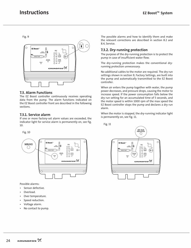
The possible alarms and how to identify them and make the relevant corrections are described in section 8.2 and 8.4, Service.
7.3.2. Dry-running protectionThe purpose of the dry-running protection is to protect the pump in case of insufficient water flow.
The dry-running protection makes the conventional dry-running protection unnecessary.
No additional cables to the motor are required. The dry run settings shown in section 9, Factory Settings, are built into the pump and automatically transmitted to the EZ Boost controller.
When air enters the pump together with water, the pump power decreases, and pressure drops, causing the motor to increase speed. If the power consumption falls below the dry run setting for an accumulated time of 5 seconds, and the motor speed is within 1000 rpm of the max speed the EZ Boost controller stops the pump and declares a dry run alarm.
When the motor is stopped, the dry-running indicator light is permanently on, see fig. 11.
Fig. 11
Fig. 9
7.3. Alarm Functions The EZ Boost controller continuously receives operating data from the pump. The alarm functions indicated on the EZ Boost controller front are described in the following sections.
7.3.1. Service alarmIf one or more factory-set alarm values are exceeded, the indicator light for service alarm is permanently on, see fig. 10.
Fig. 10
Possible alarms:
• Sensor defective.
• Overload.
• Over temperature.
• Speed reduction.
• Voltage alarm.
• No contact to pump.
LEZTL01.indd 10/4/2004, 1:42 PM24
25
Instructions EZ BoostTM System
Possible cause Remedy
The pump performance is too high compared to the inlet yield.
Replace the pump with a smaller one.
In line filter or BMQE screen is blocked.
Filter or BMQE service is required.
Restarting:After 5 minutes (factory setting), the motor will restart automatically.
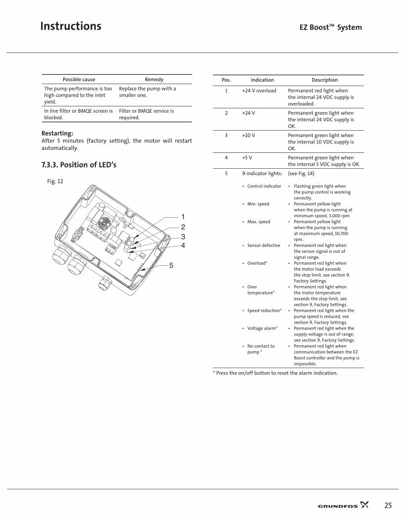
7.3.3. Position of LED’s
Fig. 12
1234
5
Pos. Indication Description
1 +24 V overload Permanent red light when the internal 24 VDC supply is overloaded.
2 +24 V Permanent green light when the internal 24 VDC supply is OK.
3 +10 V Permanent green light when the internal 10 VDC supply is OK.
4 +5 V Permanent green light when the internal 5 VDC supply is OK.
5 9 indicator lights:
• Control indicator
• Min. speed
• Max. speed
• Sensor defective
• Overload*
• Over temperature*
• Speed reduction*
• Voltage alarm*
• No contact to pump *
(see Fig. 14)
• Flashing green light when the pump control is working correctly.• Permanent yellow light when the pump is running at minimum speed, 3,000 rpm• Permanent yellow light when the pump is running at maximum speed, 10,700 rpm.• Permanent red light when the sensor signal is out of signal range.• Permanent red light when the motor load exceeds the stop limit, see section 9, Factory Settings.• Permanent red light when the motor temperature exceeds the stop limit, see section 9, Factory Settings.• Permanent red light when the pump speed is reduced, see section 9, Factory Settings.• Permanent red light when the supply voltage is out of range, see section 9, Factory Settings.• Permanent red light when communication between the EZ Boost controller and the pump is impossible.
* Press the on/off button to reset the alarm indication.
LEZTL01.indd 10/4/2004, 1:42 PM25

Instructions EZ BoostTM System
26
7.4. EZ Boost BMQE Built-in ProtectionThe EZ Boost BMQE incorporates an electronic unit which protects the motor in various situations.
• In case of overload, the built-in overload protection will stop the BMQE for 5 minutes. After that period, the booster module will attempt to restart.
• If started without water (dry running), the BMQE will stop after 30 seconds.
• If stopped as a result of dry running, the BMQE will start automatically after 5 minutes.
The motor is protected against the following conditions:
• Dry running
• Voltage surges (up to 4000 V)
• Under voltage
• Over voltage
• Overload
• Over temperature
7.4.1. Restarting the BMQE pumpTo reset the EZ Boost BMQE, switch off the electricity supply for 1 minute.
8. EZ Boost System Service8.1. EZ Boost BMQE ServiceFor the replacement and repair of parts of the EZ Boost BMQE, please refer to: 1. Service instructions for SQE pumps describing replacement of motor cable and motor.2. Parts list for SQE with instructions for dismantling and assembly of pump and motor.
8.2. EZ Boost Controller ServiceBefore starting any work on the EZ Boost controller, make sure that the electricity supply has been switched off and that it cannot be accidentally switched on.
The EZ Boost controller continuously receives operating data from the pump. In case of an alarm, the service indicator light is permanently on, see fig. 13.
CONTROL INDICATOR
MIN. SPEED
MAX. SPEED
SENSOR DEFECTIVE
OVERLOAD
OVERTEMPERATURES
SPEED REDUCTION
VOLTAGE HARM
NO CONTACT TO PUMP
Fig. 13
The service indicator light will be permanently on if one of the following alarm situations occurs:
• Sensor defective. • Overload.
• Over temperature. • Speed reduction.
• Voltage alarm. • No contact to pump.
To identify the cause of the service alarm, it is necessary to remove the front cover from the EZ Boost controller. Fit the front cover as shown in fig. 14 to avoid disconnecting the multi-core cable.
A number of LED’s are mounted on the supply board inside the EZ Boost controller, see section 7.3.3. Position of LED’s.
Fig. 14 shows the LED’s and the alarm texts on the supply board.
Fig. 14
LEZTL01.indd 10/4/2004, 1:42 PM26

27
Instructions EZ BoostTM System
8.3. EZ Boost BMQE fault finding chart
Fault Possible Cause Remedy
1. The BMQE does not run. a) The GFI or the voltage-operated GFI has tripped out.
Cut in the circuit breaker.
b) No electricity supply. Contact the electricity supply company.
c) The motor protection has cut off the electricity supply due to over-load.
Check whether the motor/pump is blocked.
d) The pump/cable is defective. Repair/replace the pump/cable.
e) Over voltage has occurred. Check the electricity supply.
2. The BMQE runs but gives no water. a) The discharge valve is closed. Open the valve.
b) The suction strainer is choked up. Pull the pump out of the sleeve and clean the strainer.
c) The pump is defective. Pull the pump out of the sleeve and repair/replace the pump.
3. The BMQE runs at reduced capacity. a) The valves in the discharge pipe are partly closed/blocked.
Check and clean/replace the valves, if necessary.
b) The discharge pipe is partly choked by impurities.
Clean/replace the discharge pipe.
c) The pump is partly choked by impurities. Pull the pump out of the sleeve. Check and clean or replace the pump, if necessary. Clean the pipes.
d) The pump is defective. Pull the pump out of the sleeve and repair/replace the pump.
e) Leakage in the pipe work. Check and repair the pipe work.
f) Under voltage has occurred. Check the electricity supply.
4. Frequent starts and stops. a) The supply voltage is unstable. Check the electricity supply.
b) The motor temperature becomes too high.
Check the water temperature.
LEZTL01.indd 10/4/2004, 1:42 PM27
Instructions EZ BoostTM System
28
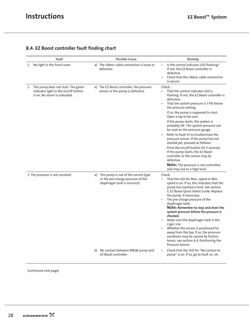
8.4. EZ Boost controller fault finding chart
Fault Possible Cause Remedy
1. No light in the front cover. a) The ribbon cable connection is loose or defective.
• Is the control indicator LED flashing? If not, the EZ Boost controller is defective.• Check that the ribbon cable connection is secure.
2. The pump does not start. The green indicator light in the on/off button is on. No alarm is indicated.
a) The EZ Boost controller, the pressure sensor or the pump is defective.
Check :• That the control indicator LED is flashing. If not, the EZ Boost controller is defective.• That the system pressure is 7 PSI below the pressure setting.
If so, the pump is supposed to start. Open a tap to be sure.
If the pump starts, the system is probably OK. The system pressure can be read on the pressure gauge.
• Refer to fault 13 to troubleshoot the pressure sensor. If the pump has not started yet, proceed as follows:
Press the on/off button for 5 seconds. If the pump starts, the EZ Boost controller or the sensor may be defective.
Note: The pressure is not controlled and may rise to a high level.
3. The pressure is not constant. a) The pump is not of the correct type or the pre-charge pressure of the diaphragm tank is incorrect.
Check• That the LED for Max. speed or Min. speed is on. If so, this indicates that the pump has reached a limit. See section 3, EZ Boost Quick Select Guide. Replace the pump, if necessary.• The pre-charge pressure of the diaphragm tank. Note: Remember to stop and drain the system pressure before the pressure is checked.• Make sure the diaphragm tank is the 2 gal. size.• Whether the sensor is positioned far away from the tap. If so, the pressure variations may be caused by friction losses, see section 6.4, Positioning the Pressure Sensor.
b) No contact between BMQE pump and EZ Boost controller.
• Check that the LED for “No contact to pump” is on. If so, go to fault no. 14.
(continued next page)
LEZTL01.indd 10/4/2004, 1:42 PM28

29
Instructions EZ BoostTM System
8.4. EZ Boost controller fault finding chart (continued)
Fault Possible Cause Remedy
4.The pump is running continuously. a) The pump cannot deliver the set pressure. The EZ Boost controller or the sensor is defective.
• Try to lower the pressure setting, see section 7.2.3. Note that the pump may run for about 15 to 20 seconds before it stops.• Check that the control indicator LED is flashing.• Check that the pipe end of the sensor is not blocked. If so, remove the blockage.• Try to stop the pump by means of the on/off button. If this is not possible, the EZ Boost controller is defective. Replace the EZ Boost controller.• Refer to fault 13 to troubleshoot the pressure sensor.
5. The EZ Boost controller indicates “No contact to pump”.
a) The pump cable is longer than 650 feet.
b) Cable breakage
c) Cross communication with adjacent EZ Boost controller.
d) The EZ Boost controller communication part is defective.
e) The BMQE motor communication part is defective.
• Reduce the length of the pump cable.
• Switch off the main power supply to the EZ Boost controller. Switch on the main power supply again. The pump is now connected direct to the main power supply without interference from the EZ Boost controller.
Does the motor start? Yes: The cable is OK. Go to point d). No: Switch off the mains supply again. Remove cable and cable plug from the motor and ohm out cable including plug. Is the cable OK? Yes: The motor is defective. Replace the motor. No: Replace the cable.
If another EZ Boost controller is installed:• If pump cables run parallel to each other physically separate them by 12 - 14 inches (305-355 mm) or rewire using shielded cable.
Are the three EZ Boost controller supply board LED’s in pos. 2, 3 and 4 on and is the control indicator LED flashing? See section 7.3.3. Yes: The mains supply is OK. Is the LED “No contact to pump” of the new EZ Boost controller also on? Yes: The EZ Boost controller is OK. Go to point e). No: The EZ Boost controller which was removed is defective.
• As a consequence of the above mentioned checks, replace the BMQE motor.
(continued next page)
LEZTL01.indd 10/4/2004, 1:42 PM29

Instructions EZ BoostTM System
30
8.4. EZ Boost controller fault finding chart (continued)
Fault Possible Cause Remedy
6. Even AFTER replacement, the EZ Boost controller indicates “No contact to pump”.
a) Numbering of BMQE pump and EZ Boost controller is different.
• If an BMQE/ EZ Boost controller system has been given a number, this number is stored in both the BMQE and EZ Boost controller. A new EZ Boost controller or BMQE may not have a number corresponding to the number stored in the previous unit. Therefore, “No contact to pump” is indicated even if there is no fault. Give the new system the number used in the previous unit in order to obtain correspondence between the number- ing of the BMQE pump and the EZ Boost controller. This requires an R100.
Note: Two systems on the same main power supply must not have the same number!
7. The EZ Boost controller indicates “Over voltage” or “Under voltage”.
a) The supply voltage is unstable or outside the voltage range specified for the installed motor type.
• Check: Possibly over a period of time - that the supply voltage is according to the values in Section 5.
Note: As the voltage is detected at the motor, allow for the voltage drop in the pump cable.
8. The EZ Boost controller indicates “Dry running”.
If the power consumption is lower than the dry-running stop setting and the motor speed is within 1000 rpm of programmed maximum speed, for an accumulated period of 5 seconds, the pump will be stopped.
a) The pump performance is too high for the inlet yield.
b) The well screen is blocked.
• Replace the pump with a smaller pump or reduce the pump performance, by lowering maximum speed, or reducing set pressure.
• Check the well capacity and restore water supply to the well.
9. The EZ Boost controller indicates “Speed reduction” and “Under voltage”.
Speed reduction is activated so as to maintain a reduced performance. When the supply voltage falls so low that it can no longer supply the necessary current to maintain 3,000 rpm, the pump will be stopped.
a) The supply voltage is unstable or lower than the voltage range specified for the installed motor type.
b) The pump is not of the correct type.
c) The voltage drop in the pump cable is too great.
• Restore correct supply voltage.
• Install correct pump type.
• Replace the pump cable with lower gauge wires or reduce cable length.
(continued next page)
LEZTL01.indd 10/4/2004, 1:42 PM30

31
Instructions EZ BoostTM System
8.4. EZ Boost controller fault finding chart (continued)
Fault Possible Cause Remedy
10. The EZ Boost controller indicates “Speed reduction” and “Overload”.
Speed reduction is activated so as to maintain a reduced performance
a) The pump is worn or blocked.b) The pump is too large for the installed motor.
• The pump must be serviced.
• Replace pump or motor.
11. The EZ Boost controller indicates “Over temperature”.
The temperature sensor in the motor is sensing a temperature above the values stated in Section 9, Factory settings:
a) Insufficient cooling of the motor. • Restore correct cooling of the motor. The flow velocity past the motor should be at least 0.5 ft/s (0.15 m/s).
12. The EZ Boost controller indicates “Overload”.
a) The pump is worn or blocked.b) The pump is too large for the installed motor.
• The pump must be serviced.
• Replace pump or motor.
13. The EZ Boost controller indicates “Sensor defective”.
a) The pressure sensor is defective. • Check that the sensor is wired correctly. If the sensor type is 4-20 mA, measure the DC voltage across the sensor input terminals. If the DC voltage measured at the sensor input terminals is not between 2 and 10 volts the sensor, or wiring is defective. Refer to Section 10, Pressure Sensor Voltage Chart. Replace defective parts. Are the LED “Sensor defective” and the LED, pos. 1, on? See section 7.3.3., Position of LED’s.
Yes: The total load of 24 VDC from terminal 5 is above 100 mA. Disconnect the sensor in order to determine if it is defective. Replace defective sensor.
No: The load is OK, but the EZ Boost controller sensor input may be defective.
14. The pump is operating on/off. a) No communication. • Check that the LED “No contact to pump” is on.
If so, the control unit EZ Boost controller starts and stops the pump, based on the sensor signal only. The EZ Boost controller has to be reset after each 250 stop.- see fault no. 5 for remedy
LEZTL01.indd 10/4/2004, 1:42 PM31

Instructions EZ BoostTM System
32
8.5. Instruments not allowedNote: The use of the following instruments is not allowed during fault finding:
Note: When measuring, use RMS-instruments.
8.6. Checking of motor and cable1. Supply voltage Measure the voltage (RMS) between
line and neutral. Connect the voltmeter to the terminals at the connection.
When the motor is loaded, the voltage should be within the range specified in section 5, Technical Data.
Large variations in supply voltage indicate poor electricity supply, and the BMQE should be stopped until the defect has been remedied.
2. Current consumption Measure the current (RMS) while the pump is operating at a constant discharge head (if possible, at the capacity where the motor is most heavily loaded).
For maximum current, see nameplate.
If the current exceeds the full load current, there are the following possible faults:
• Poor connection in leads, possibly in the cable joint.
• Too low supply voltage, see item 1.
9. Factory settings
Alarm
200-240 V motors 100-115 V motors
SQ/SQE/SQE-NE 03A and 05A models
SQ/SQE/SQE-NE05B and 07B models
SQ/SQE/SQE-NE1.0C and 1.5C models
All models
Sensor defective 4-20 mA (the value is stored in the EZ Boost controller)
Overload 5 A 8 A 11 A 11 A
Over temperature Stop limit: 149°F (65°C)
Stop limit: 167°F (75°C)
Stop limit: 185°F (85°C)
Stop limit:185°F (85°C)
Restart: 131°F (55°C)
Restart:149°F (65°C)
Restart: 167°F (75°C)
Restart:167°F (75°C)
Speed reduction In connection with under voltage or overload
Over voltage *) 320 VAC 320 VAC 320 VAC 185 VAC
Under voltage Speed reduction: 190 VStop limit: 150 V
Speed reduction: 190 VStop limit: 150 V
Speed reduction: 190 VStop limit: 150 V
Speed reduction: 190 VStop limit: 75 V
Dry-running 300 W 680 W 800 W 300 W
*) 200-240 V motors: Operation is guaranteed up to 280 VAC, 100-115 V motors: Operation is guaranteed up to 150 VAC. In order to avoid unnecessary stops, the over voltage stop limit is as stated.
LEZTL01.indd 10/4/2004, 1:42 PM32

10. Pressure sensor voltage chartVoltage to pressure chart for EZ Boost pressure sensors. Measure DC voltage between Sensor IN and Sensor Ground.Voltages less than 2 or greater than 10 indicate an incorrectly wired or a faulty sensor.
DC voltage psi DC voltage psi DC voltage psi1.9 0.0 4.5 40.5 7.1 81.02.0 0.7 4.6 41.2 7.2 81.72.0 1.5 4.6 42.0 7.2 82.52.1 2.2 4.7 42.7 7.2 83.22.1 3.0 4.7 43.5 7.3 84.02.2 3.7 4.8 44.2 7.3 84.72.2 4.5 4.8 45.0 7.4 85.52.3 5.2 4.8 45.7 7.4 86.22.3 6.0 4.9 46.5 7.5 87.02.4 6.7 4.9 47.2 7.5 87.72.4 7.5 5.0 48.0 7.6 88.52.4 8.2 5.0 48.7 7.6 89.22.5 9.0 5.1 49.5 7.7 90.02.5 9.7 5.1 50.2 7.7 90.72.6 10.5 5.2 51.0 7.8 91.52.6 11.3 5.2 51.7 7.8 92.22.7 12.0 5.3 52.5 7.9 93.02.7 12.8 5.3 53.2 7.9 93.72.8 13.5 5.4 54.0 8.0 94.52.8 14.3 5.4 54.7 8.0 95.22.9 15.0 5.5 55.5 8.1 96.02.9 15.7 5.5 56.2 8.1 96.73.0 16.5 5.6 57.0 8.2 97.53.0 17.2 5.6 57.7 8.2 98.23.1 18.0 5.7 58.5 8.3 99.03.1 18.7 5.7 59.2 8.3 99.73.2 19.5 5.8 60.0 8.4 100.53.2 20.2 5.8 60.7 8.4 101.33.3 21.0 5.9 61.5 8.4 102.03.3 21.7 5.9 62.2 8.5 102.83.4 22.5 6.0 63.0 8.5 103.53.4 23.2 6.0 63.7 8.6 104.33.5 24.0 6.0 64.5 8.6 105.03.5 24.7 6.1 65.2 8.7 105.83.6 25.5 6.1 66.0 8.7 106.53.6 26.2 6.2 66.7 8.8 107.33.6 27.0 6.2 67.5 8.8 108.03.7 27.7 6.3 68.2 8.9 108.83.7 28.5 6.3 69.0 8.9 109.53.8 29.2 6.4 69.7 9.0 110.33.8 30.0 6.4 70.5 9.0 111.03.9 30.7 6.5 71.2 9.1 111.83.9 31.5 6.5 72.0 9.1 112.54.0 32.2 6.6 72.7 9.2 113.34.0 33.0 6.6 73.5 9.2 114.04.1 33.7 6.7 74.2 9.3 114.84.1 34.5 6.7 75.0 9.3 115.54.2 35.2 6.8 75.7 9.4 116.34.2 36.0 6.8 76.5 9.4 117.04.3 36.7 6.9 77.2 9.5 117.84.3 37.5 6.9 78.0 9.5 118.54.4 38.2 7.0 78.7 9.6 119.34.4 39.0 7.0 79.5 9.6 120.04.5 39.7 7.1 80.2
33
Instructions EZ BoostTM System
LEZTL01.indd 10/6/2004, 3:51 PM33

LEZTL01.indd 10/4/2004, 1:42 PM34

LIMITED WARRANTYProducts manufactured by GRUNDFOS PUMPS CORPORATION (GRUNDFOS) are warranted to the original user only to be free of defects in material and workmanship for a period of 24 months from date of installation, but not more than 30 months from date of manufacture. GRUNDFOS’ liability under this warranty shall be limited to repairing or replacing atGRUNDFOS’ option, without charge, F.O.B. GRUNDFOS’ factory or authorized service station, any product of GRUNDFOS’ manufacture. GRUNDFOS will not be liable for any costs of removal, installation, transportation, or any other charges which may arise in connection with a warranty claim. Products which are sold but not manufactured by GRUNDFOS are subject to the warranty provided by the manufacturer of said products and not by GRUNDFOS’ warranty. GRUNDFOS will not be liable for damage or wear to products caused by abnormal operating conditions, accident, abuse, misuse, unauthorized alteration or repair, or if the product was not installed in accordance with GRUNDFOS’ printed installation and operating instructions.
To obtain service under this warranty, the defective product must be returned to thedistributor or dealer of GRUNDFOS’ products from which it was purchased together with proof of purchase and installation date, failure date, and supporting installation data. Unlessotherwise provided, the distributor or dealer will contact GRUNDFOS or an authorized service station for instructions. Any defective product to be returned to GRUNDFOS or a service station must be sent freight prepaid; documentation supporting the warranty claim and/or a Return Material Authorization must be included if so instructed.
GRUNDFOS WILL NOT BE LIABLE FOR ANY INCIDENTAL OR CONSEQUENTIAL DAMAGES, LOSSES, OR EXPENSES ARISING FROM INSTALLATION, USE, OR ANY OTHER CAUSES. THERE ARE NO EXPRESS OR IMPLIED WARRANTIES, INCLUDING MERCHANTABILITY OR FITNESS FOR APARTICULAR PURPOSE, WHICH EXTEND BEYOND THOSE WARRANTIES DESCRIBED OR REFERRED TO ABOVE.
Some jurisdictions do not allow the exclusion or limitation of incidental or consequentialdamages and some jurisdictions do not allow limitations on how long implied warranties may last. Therefore, the above limitations or exclusions may not apply to you. This warranty gives you specific legal rights and you may also have other rights which vary from jurisdictionto jurisdiction.
LEZTL01.indd 10/4/2004, 1:42 PM35

L-EZ-TL-001 Rev. 10/04PRINTED IN USA
Bombas Grundfos de Mexico, S.A. de C.V.Boulevard TLC #15Parque Stiva AeropuertoApodaca, N.L. Mexico C.P. 66600 Telephone: 52-81-8144-4000Fax: 52-81-8144-4010
North American Regional HeadquartersGrundfos Pumps Corporation17100 W. 118th TerraceOlathe, KS 66061Telephone (913) 227-3400Fax: (913) 227-3500
www.grundfos.com
Grundfos Canada, Inc.2941 Brighton RoadOakville, Ontario L6H 6C9, CanadaTelephone: (905) 829-9533Fax: (905) 829-9512
Grundfos Pumps Corporation17100 W. 118th TerraceOlathe, KS 66061Telephone 913 227 3400Fax: 913 227 3500
www.grundfos.com
Grundfos Canada, Inc.2941 Brighton RoadOakville, Ontario L6H 6C9 CanadaTelephone: 905 829 9533Fax: 905 829 9512
Bombas Grundfos de Mexico, S.A. de C.V.Boulevard TLC #15Parque Stiva AeropuertoApodaca, N.L. 66600 Mexico Telephone: 52 81 8144 4000Fax: 52 81 8144 4010
Being responsible is our foundation
Thinking ahead makes it possible
Innovation is the essence
Subject to alterations
LEZTL01.indd 10/4/2004, 1:42 PM36