Embed Size (px)
Citation preview

Signal & Image Processing: An International Journal (SIPIJ) Vol.11, No.5, October 2020
DOI: 10.5121/sipij.2020.11501 1
EYE GAZE ESTIMATION INVISIBLE AND IR
SPECTRUM FOR DRIVER MONITORING SYSTEM
Susmitha Mohan and Manoj Phirke
Imaging and Robotics Lab, HCL Technologies, Bangalore
ABSTRACT Driver monitoring system has gained lot of popularity in automotive sector to ensure safety while driving.
Collisions due to driver inattentiveness or driver fatigue or over reliance on autonomous driving features
arethe major reasons for road accidents and fatalities. Driver monitoring systems aims to monitor various
aspect of driving and provides appropriate warnings whenever required. Eye gaze estimation is a key
element in almost all of the driver monitoring systems. Gaze estimation aims to find the point of gaze which
is basically,” -where is driver looking”. This helps in understanding if the driver is attentively looking at
the road or if he is distracted. Estimating gaze point also plays important role in many other applications
like retail shopping, online marketing, psychological tests, healthcare etc. This paper covers the various
aspects of eye gaze estimation for a driver monitoring system including sensor choice and sensor
placement. There are multiple ways by which eye gaze estimation can be done. A detailed comparative
study on two of the popular methods for gaze estimation using eye features is covered in this paper. An infra-red camera is used to capture data for this study. Method 1 tracks corneal reflection centre w.r.t the
pupil centre and method 2 tracks the pupil centre w.r.t the eye centre to estimate gaze. There are
advantages and disadvantages with both the methods which has been looked into. This paper can act as a
reference for researchers working in the same field to understand possibilities and limitations of eye gaze
estimation for driver monitoring system.
KEYWORDS Driver monitoring system. eye gaze estimation, pupil, iris, cornea, corneal reflection, polynomial curve
fitting, infra-red camera, infra-red illuminators
1. INTRODUCTION
Driver monitoring system has emerged as an important application to enable safety as the major
cause for road accidents are due to driver not giving required attention. Distracted driving, driver fatigue and over reliance on autonomous driving features of car are three key aspects monitored
by driver monitoring systems. Though there are multiple types of sensors that can provide
information related to driver attentiveness, drowsiness and driver health, camera-based solutions are most popular for its ability to derive various kinds of information from image sequence/video.
Eye gaze estimation is one of the most important modules of driver monitoring systems as it
provides a lot of information about the attention and focus of the driver. Gaze estimation detects the point of gaze. If the gaze is not present on road beyond predefined threshold, then multiple
actions can be taken by car. These actions include audible warnings, vibrating seats, disabling
autonomous driving features, reducing speed of vehicle slowly so that driver stops vehicle on side
/ parking, notifying family members, notifying companies whose vehicles are being driven as well as to insurance company. This way DMS (Driver Monitoring System) can ensure that the
driver is attentive enough on driving.

Signal & Image Processing: An International Journal (SIPIJ) Vol.11, No.5, October 2020
2
Gaze estimation is useful in multiple ways in various other fields as well. It is important for the web designers to understand where people gaze most on the screen and where not. This
information helps them to place the right information and editing fields or buttons at the right
place. In healthcare the information about eye gaze variation helps to diagnose some of the
neurological disorders / developmental disorders like autism. Gaze estimation is crucial in order to have responsive and comfortable augmented or virtual reality. Vision aided applications also
make use of eye gaze estimation to help the user.
There are different ways by which gaze estimation can be done. Some of the methods uses
wearable gadgets whereas some doesn’t. Analysing movement of pupil w.r.t eye and movement
of corneal reflection w.r.t pupil has gained a lot of attraction due to its simplicity and robustness. This movement of the eye features has been interpreted mathematically in various ways. For
interpolation and extrapolation of data, methods like polynomial fitting and gaussian fitting are
widely used.
With increasing popularity and usability of gaze estimation, the accuracy and efficiency of gaze
estimation has become important focus area. Amount of accuracy and efficiency required can be
different from one application to another application. Also, the minimum gaze angle to be measured varies with the kind of application it is used for. The type of environment and the
lighting also plays a significant role in the selection of sensor and method for gaze estimation.
The lighting variations inside a car can be more when compared to an indoor environment and hence the technology suiting an indoor application might not fit for driver gaze estimation. In
case of person wearing spectacles or goggles gaze estimation is challenging and sometimes
impossible when the eyes are fully occluded. For accurate estimation of eye gaze and for gaze
estimation under challenging scenarios more sophisticated devices and techniques are used.
There is intense research happening over decades to improve the eye gaze estimation
performancefor driver monitoring systems. Solution for continuous driver gaze estimation in real-world driving situations is proposed in [1], combining multi-zone ICP-based head pose tracking
and appearance-based gaze estimation. Various aspects of gaze estimation systems, algorithms
and performance evaluation methods in consumer platforms are reviewed and presented in [2]. In
[3] a system to estimate driver's gaze from head and eye cues projected on a multi-plane geometrical environment and a system which fuses the geometric with data driven learning
method is proposed. Method for improving the accuracy of gaze estimation by deblurring the
blurred images of a driver from the vehicle is explained in [4]. This study is the first attempt to calculate a driver’s gaze by deblurring a motion blurred image with CycleGAN, whereas
simultaneously using the image information from the two cameras in the vehicle. In [5] a real-
time algorithm to estimate the head pose in terms of roll, yaw and pitch based on face-geometry is proposed. Recent trends and developments happening in gaze estimation is present in [8], [9],
[10]. In [6] visible light is used to obtain the corneal reflection instead of IR lighting. An efficient
method of using geometric transforms in homography normalization (HN) method when corneal
reflections are lesser than 4 in number is present in [11]. The possibility of accurately detecting and tracking human gaze based on the head pose information extracted by an RGB-D device is
present [12]. A mapping function based on artificial neural networks is used in [13]. How well
Gaussian process adapt to the non-linearity in eye movement over polynomial regression is presented in [7]. In [14] Fourier descriptors are used to describe the appearance-based features of
eyes compactly. Shape and intensity based deformable eye pupil-centre detection and movement
decision algorithms is present in [15]. An effective way of estimating eye gaze from the elliptical features of one iris is described in [16]. An investigation on the effect of gaze position on pupil
size estimation by three common eye-tracking systems is presented in [17]. A low-cost system
which uses web camera and open source Computer Vision Library Open CV is proposed in [18].

Signal & Image Processing: An International Journal (SIPIJ) Vol.11, No.5, October 2020
3
In [19] and [20] review of different eye tracking systems for diagnostic interpretation is presented. A review of eye gaze estimation techniques and applications for consumer products,
which has progressed in diverse ways over the past two decades is presented in [21]. In [22] a
new hardware friendly, convolutional neural network (CNN) model with minimal computational
requirements is introduced and assessed for efficient appearance-based gaze estimation.
In this paper various aspects of eye gaze estimation for driver monitoring have been studied.
Some of the real-world scenarios to be addressed by DMS system are described in section 2. Off road and on road points for a driver driving a car are shown in section 3. Viewing these different
zones without changing the head-pose is not comfortable. The need to incorporate head
orientation in gaze angle calculation is also described under section 3. Different options for sensor placement and choice of sensors for gaze estimation are described in section 4. Various
eye features used for gaze estimation by two of the popular gaze estimation methods are
discussed in detail in the subsequent sections. Method 1 will be referred to as ’corneal reflection-
based gaze estimation’ and method 2 will be referred to as ’pupil-based gaze estimation’ in the rest of the paper. Pupil based gaze estimation can work with visible as well as infrared radiation
(IR) camera whereas corneal reflection-based method needs an IR camera to function. For one to
one comparison purpose; data captured from an IR camera is used for both pupil based and corneal reflection-based analysis as both the eye features are visible in IR data. This paper is
hence a comparison of what can be achieved with an IR camera and without an IR camera
predominantly from driver monitoring system perspective.
2. REAL WORLD SCENARIOS
For driver monitoring systems it is important to consider various real time scenarios like
changing weather conditions, lighting variations, road dynamics and other environmental factors. Gaze estimation algorithms should be able to function properly in-spite of these variations. For
imaging-based solutions, lighting variations play a critical role in deciding the system
performance. During day time the challenges would be image saturation, sun glare etc. whereas during night time lack of proper lighting sometimes oncoming vehicle headlamp / bright street
lights makes system functioning difficult. There will also be scenarios like the vehicle passing
through a tunnel or an under pass where the lighting is low and the facial features are not clearly
visible. In-order to function properly in all these various scenarios, IR cameras along with IR illuminators are preferred than visible spectrum cameras. More details about IR camera and IR
illuminators are given under section 4.
There are multiple other dynamic scenarios that needs to be addressed by a driver monitoring
system as the chances of driver getting distracted from driving are high in practical driving
scenarios. The distraction might be due to some of the external factors like other vehicles on
road, advertisements, sign boards, road construction, a crash scene or a good scenery. Almost all ADAS (Automotive Driver Assistance Systems) or autonomous driving systems require driver to
be attentive and ready to take control of vehicle in order to avoid accidents.Looking at news
about Tesla and other vehicles; it is clear that drivers become too reliant on these features endangering themselves and others on road. It is also possible that other co-passengers or pets
that are not contained distract the driver. Driver might also get distracted by a phone call or by
looking into the infotainment system or navigation system.Adjusting vehicle controls like air conditioning, tilt of steering wheel, mirrors, seat position, dash light brightness etc can also be
considered as distractions. Eating, drinking, reading, smoking, grooming etc. are all distractions.
These distractions can lead to reduced situational awareness, inability to make quick decisions
and execute emergency actions, recognize and obey traffic signals and signs, avoid collisions with parked vehicles, maintain proper lane etc. Driver monitoring system should be able to

Signal & Image Processing: An International Journal (SIPIJ) Vol.11, No.5, October 2020
4
identify if the driver is attentive enough in driving in-spite of all these possible distractions. Also, the system should identify the duration for which the distracted gaze persists so that warning/alert
can be triggered.
3. VIEWING ZONES
3.1. Safe and unsafe viewing zones As mentioned in section 2, there are various real-time scenarios that needs to be addressed by a
driver monitoring system. As eye gaze is pivotal in understanding if the driver is attentive or
distracted, gaze estimation algorithms are inevitable in driver monitoring systems. In order to
provide alerts for distracted driving, the view zones need to be classified as safe (on the road) and unsafe (off the road)zones. Eyes off the road (EOR) detection requires this clear demarcation to
be made between on the road and off the road points. Whenever the gaze falls off the road
appropriate alerts has to be provided. The alerts can be provided based on the time duration for which the gaze is fixed off the road.
Figure 1 shows various gaze points that are used for gaze related experiments in this paper. Points
P12, P13, P15 and P16 are on the road points and all points except these four points are off road points. Driver gaze has to be mostly on ‘on road points’ unless and otherwise there is a need to
gaze at other points like the side mirror or rear-view mirror etc.
Figure 1. Eyes on the road points
Study has been done on the typical time duration taken by the driver to gaze at various off-road points. Table 1 has typical gaze timings for different off road zones and the thresholds
recommended to initiate the warning system at different speeds.

Signal & Image Processing: An International Journal (SIPIJ) Vol.11, No.5, October 2020
5
Table 1: Typical gaze timings at various off-road zones
Gaze point Avg gaze
timing(s)
observed
Recommended threshold(s) to initiate warning system at
vehicle speed:
10 km/h
= 2.78 m/s
20 km/h
= 5.56 m/s
50 km/h
= 13.89 m/s
100 km/h
= 27.78 m/s
P6 - Reading speed of
vehicle from
instrument cluster
0.995 3.6 s 1.8 s 720 ms 360 ms
P11 - Viewing rear
view mirror 0.960 4.3 s 2.2 s 860 ms 430 ms
P27 - Right side view 1.806 4.3 s 2.2 s 860 ms 430 ms
P17 - Left side view 1.500 4.3 s 2.2 s 860 ms 430 ms
P21 - Changing song
to next by pressing
button on infotainment
system
1.182 3.6 s 1.8 s 720 ms 360 ms
P22 - Changing audio
volume 1.210 3.6 s 1.8 s 720 ms 360 ms
P23 - AC control 1.720 3.6 s 1.8 s 720 ms 360 ms
P25 - Using power
window controls 1.409 3.6 s 1.8 s 720 ms 360 ms
Assumptions:
1. 10 meters ahead might be a safe distance to drive without eyes on the road, provided the road is
free and no vehicles are expected to come within the 10 meters when eyes are off the road.
2. Viewing left, right and rear-view mirror are essential tasks to be performed by the driver when
compared to other tasks like audio/AC control etc and hence a higher threshold might be
provided for the essential tasks.
3. The time values calculated includes the total time taken for gaze shift from on road point to off
road point and back
At higher vehicle speeds the thresholds recommended for off road gaze timings are much lesser
than the typical gaze timings observed as the time taken to cover 10m will be less.This early
warning shall help to bring the driver focus back on road quickly or prompt the driver to slow the vehicle before the gaze is fixed off the road.
3.2. Comfortable Gaze Zones and Need for Head Pose Estimation
Not all points marked in figure 1 can be viewed comfortably by the driver without making any
head movement. In this paper the term ‘comfortable gaze zone’ refers to the zone/region the driver can view effortlessly without making any head movement. An analysis on comfortable
gaze zone is done by collecting data from different people sitting in the driver seat and looking at
various points marked inside the car. Figure 2 shows the comfortable gaze zone marked in green
colour with data collected from multiple people.
From the study it is observed that all the people could comfortably view points on steering wheel,
instrument cluster, centre cluster and on road points without making any head movement. For most of the people the AC control, rear view mirror, driver visor, and left window lock can be
viewed comfortably without making much head movement. To view the centre lock, gear and
points lying of the left part of windshieldpeople tends to move the head slightly. For viewing the left mirror significant head movement was made by all the people.

Signal & Image Processing: An International Journal (SIPIJ) Vol.11, No.5, October 2020
6
Head movement adds one level of complexity to the gaze estimation techniques, wherein the head pose also needs to be incorporated in eye gaze estimation. Rotation of head in all three
dimensions measured as roll, yaw and pitch has to be accurately measured and incorporated in
gaze angle calculation in-order to find the gaze point accurately. Error in head pose estimation
will accumulate in the gaze angle calculation and the gaze point detected will shift from the actual point.
Figure 2. Comfortable gaze zone
4. SENSOR
4.1. Sensor placement
There are multiple options for camera placement for a driver monitoring system. Since in most of the cases the image from camera will be used for multiple algorithms like drowsiness detection,
gaze and distraction estimation etc, it is important to consider the camera placement that will
work optimally for all the different applications.
Figure 3. Different options for camera placement

Signal & Image Processing: An International Journal (SIPIJ) Vol.11, No.5, October 2020
7
Systems with camera placed behind the steering in the top middle part of the instrument cluster (A) are most popular. In this case the camera is placed in such a way that the steering wheel
doesn’t occlude the camera most of the time. It is possible to integrate the camera into the
instrument cluster using the same processor that drives the cluster. This approach helps in cost
saving as there is no need for separate camera housing, cables and embedded system. It is also observed that placing the camera lower helps detect eye features accurately than keeping the
camera on top or on sides.
Few systems use CCD camera and illuminators embedded into the steering (B) itself. This gives
better view of eye and other facial features, but comes with the risk of getting covered by driver’s
hands.
Placing camera on top of dashboard or sticking camera and illuminators to the lower end of
windshield(C) are other options. But these two are least preferred methods as it might occlude the
driver’s view and are not aesthetically pleasing.
There are systems with camera placed on the A-pillar (D) or camera embedded into the
infotainment cluster(E), both providing the side view of the face. The advantage with this approach is not to have the camera in front of the driver occluding his view. But it is challenging
for most of the imaging algorithms to work with images from side-view. Algorithms usually
works better with frontal face images than with side face images.
Keeping camera near the rear-view mirror(F) is another approach which is commonly used to
cover a wider area inside the car. Such systems usually monitor other co-passengers along with
the driver. But this gives a top view which is not ideal for capturing eye features clearly and hence is not a good option for drowsiness detection as well as distraction detection.
4.2. Choice of Sensor
There are different kinds of sensors used in driver monitoring systems. Most of the systems use
camera to capture images of driver’s face, understand driver’s conditions based on head movements and facial features. Infrared cameras are most widely used for driver monitoring
systems. Cameras operating in visible spectrum (typical USB/ mobile cameras) are seldom used.
Few systems use thermal cameras for monitoring temperature that can indicate health condition of the driver. Mm wave sensors can also be used for monitoring driver health. Use of
physiological sensors like Electroencephalogram (EEG), Electrocardiogram (ECG),
Electrooculography (EOG), Electromyography (EMG), Electro-Dermal Activity (EDA), Skin Temperature (ST) sensors etc. are also being explored for usage in driver monitoring systems.
Sensors that monitors the driving pattern from the movements in car steering, acceleration and
breaking also help in understanding driver fatigue, distraction or rash driving. Most of the
advanced driver monitoring systems has sensor fusion where the signals from more than one sensor are used. Among all the different types of sensors, cameras are most popular as it can
accumulate data in nonintrusive way for a wider view angle. Also, the installation and
maintenance charges are low for cameras. Extensive information can be extracted from images. But imaging algorithms usually requires more computing resources to process the image.
In this paper only camera-based/ imaging-based solutions are discussed. Under various real time
scenarios, using an IR camera along with IR illuminators works better compared to visible spectrum cameras. Instead of the 400–700 nanometre range of the visible light camera, infrared
cameras are sensitive to wavelengths from about 1,000 nm (1 μm) to about 14,000 nm (14
μm).IR illuminators doesn’t cause any disturbance to human eyes as it falls outside the visible
Signal & Image Processing: An International Journal (SIPIJ) Vol.11, No.5, October 2020
8
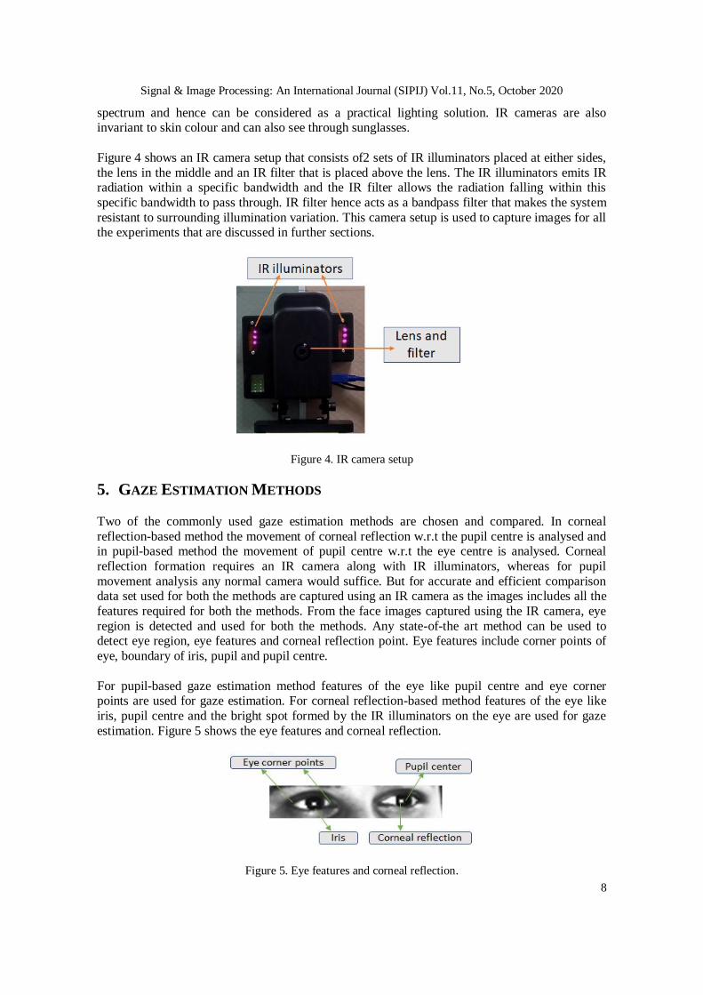
spectrum and hence can be considered as a practical lighting solution. IR cameras are also invariant to skin colour and can also see through sunglasses.
Figure 4 shows an IR camera setup that consists of2 sets of IR illuminators placed at either sides,
the lens in the middle and an IR filter that is placed above the lens. The IR illuminators emits IR radiation within a specific bandwidth and the IR filter allows the radiation falling within this
specific bandwidth to pass through. IR filter hence acts as a bandpass filter that makes the system
resistant to surrounding illumination variation. This camera setup is used to capture images for all the experiments that are discussed in further sections.
Figure 4. IR camera setup
5. GAZE ESTIMATION METHODS
Two of the commonly used gaze estimation methods are chosen and compared. In corneal
reflection-based method the movement of corneal reflection w.r.t the pupil centre is analysed and in pupil-based method the movement of pupil centre w.r.t the eye centre is analysed. Corneal
reflection formation requires an IR camera along with IR illuminators, whereas for pupil
movement analysis any normal camera would suffice. But for accurate and efficient comparison data set used for both the methods are captured using an IR camera as the images includes all the
features required for both the methods. From the face images captured using the IR camera, eye
region is detected and used for both the methods. Any state-of-the art method can be used to detect eye region, eye features and corneal reflection point. Eye features include corner points of
eye, boundary of iris, pupil and pupil centre.
For pupil-based gaze estimation method features of the eye like pupil centre and eye corner points are used for gaze estimation. For corneal reflection-based method features of the eye like
iris, pupil centre and the bright spot formed by the IR illuminators on the eye are used for gaze
estimation. Figure 5 shows the eye features and corneal reflection.
Figure 5. Eye features and corneal reflection.

Signal & Image Processing: An International Journal (SIPIJ) Vol.11, No.5, October 2020
9
To understand the variations in eye features with gaze change, an IR camera is placed in between the person and a fixed pattern. The fixed pattern has markings in both vertical and horizontal
directions to gaze at. To compare the pupil movement and corneal reflection movement images of
eyes are captured using the IR camera looking at the frontal face of the person. Figure 6 shows
the fixed pattern and the camera setup used for capturing data.
Figure 6. Pattern used to fix gaze at various horizontal and vertical angles
Images of eyes at different gaze angle are captured using the IR camera. When the gaze changes from one point to the next point on the fixed pattern only the eyes are moved without any head
movement. Sets of images are captured with eye gaze varying in horizontal direction from left to
right with an offset of 5 degree and the vertical gaze angle kept constant. On successful completion of one set of horizontal data capture the vertical gaze is changed to 5 degree up or
down and next set of horizontal eye gaze data is captured. The maximum variation in eye gaze in
horizontal direction is from -45 degree to +45 degree and in the vertical direction is from -30
degree to +30 degree using the pattern shown in figure 6.
5.1. Corneal Reflection-Based Gaze Estimation
Near-infrared light directed towards the eyes forms bright reflections on the cornea called corneal
reflection. As there are two sets of illuminators placed on either side of the lens, two bright spots
are formed on the cornea. Centre of these two bright spots is referred to as corneal reflection centre in the whole paper and this spot is considered for the analysis. With the changes in eye
gaze the corneal reflection centre moves around the pupil in some specific pattern. This specific
pattern helps to estimate gaze angle. Tofind the relation between corneal reflection movement and gaze angle, measurements shown in (1), (2) and (3) are used.
x = |PupilCenter_x – CornealReflectionCenter_x| (1)
y = |PupilCenter_y – CornealReflectionCenter_y| (2)
R = Radius of iris (3)
Figure 7 has x,y and R marked
Figure 7. Measurements for gaze estimation from corneal reflection

Signal & Image Processing: An International Journal (SIPIJ) Vol.11, No.5, October 2020
10
5.1.1. Horizontal gaze estimation using corneal reflection
To estimate horizontal gaze angle from corneal reflection eye gaze is shifted only in the
horizontal direction from left to right and vertical gaze angle kept constant. It is observed that
when camera is aligned with the centre of face and the gaze is at the centre of the fixed pattern then the corneal reflection centre overlaps with the centre of pupil. When the gaze shifts towards
left from the centre of the pattern then the corneal reflection moves towards right from the pupil
centre. And when the gaze shifts towards right from the centre of the pattern then the corneal reflection moves towards left from the pupil centre. The corneal reflection moves farther from the
pupil centre when the gaze shifts more towards left or right from the centre of the pattern. But
this relation is not linear. To find the relation between corneal reflection position and horizontal gaze angle ’x/R’ is calculated for different horizontal gaze angles with vertical gaze angle kept
constant. Instead of ’x’ and ’y’, ’x/R’ and ’y/R is used in the analysis to remove the dependency
on image resolution and distance from the camera. The values obtained for ’x/R’ for varying
horizontal angles are as shown in Figure 8.
Figure 8. x/R values for different gaze angles
It is clear from the values that the relation is not linear as the difference between subsequent
values is not constant. To find the non-linear relation connecting corneal reflection position with
eye gaze angle, ’x/R’ is plotted against horizontal eye gaze and different curve fittings are tried on these calibration points.
Figure 9. x/R vs gaze angle plot

Signal & Image Processing: An International Journal (SIPIJ) Vol.11, No.5, October 2020
11
From figure 9 it can be observed that a third order polynomial is fitting the calibration points effectively. For easy comparative analysis polynomial regression is preferred in this paper over
Gaussian or other methods. As the relation between horizontal gaze angle and corneal reflection
position is established as a polynomial function, it is possible to calculate the gaze angle from the
iris dimensions, pupil and corneal reflection centre position.
HorzGazeAngle = −0.436 + 84.419(x/R)+ −0.694(x/R) 2 + −33.535(x/R) 3 (4)
For a given person the relation represented in 4 is true for varying distance between camera and
eyes. This relation is also true at varying vertical eye gaze angle. Figure 10 has ’x/R’ values at
different vertical gaze angle and horizontal gaze angle kept constant(30 degree).
Figure 10. x/R at varying vertical gaze angle
Asobserved in figure 10 ’x/R’ is a constant at different vertical gaze angle with horizontal gaze
angle kept constant.
When camera is not aligned with the centre of both eyes, then there is a shift in the polynomial curve from zero. The curve plotted in Figure 11 is with the camera shifted towards right by 10
degrees.
Figure 11. Shift in curve fitting with the shift in camera alignment
It is important that any gaze estimation method should be generic enough to work on multiple people. To check how generic is curve fitting method for gaze estimation, eye images with
horizontal gaze varying from -50 to +50 degree and vertical gaze angle kept as zero is collected

Signal & Image Processing: An International Journal (SIPIJ) Vol.11, No.5, October 2020
12
from different people and a third order polynomial curve is fitted on these calibration points. Figure 12 has values from 3 different people marked in three different colours. The error in curve
fitting is calculated and is found to be minimal. Error values of each coefficient of curve fitting
has values as shown in table 2.
Figure 12. x/R values from 3 different people
Table 2: Error values of polynomial coefficients
Coeff Value Error
a 0.26 0.638
b 81.85 2.192
c -0.79 2.024
d -34.82 4.576
The polynomial curve in figure 12 is used to estimate gaze for person 1,2 and 3 and the error in gaze estimation is obtained as 1.33 degree, 1.61 degree and 1.11 degree respectively. When ’y/R’
is plotted against varying horizontal eye gaze angles (with vertical gaze angle kept constant) then
the plot as shown in Figure 13 is obtained. As observed from Figure 13 ’y/R’ is constant for different horizontal eye gaze angle.
Figure13. Horizontal gaze vs y/R

Signal & Image Processing: An International Journal (SIPIJ) Vol.11, No.5, October 2020
13
5.1.2. Vertical gaze estimation using corneal reflection
Similar experiments which are done for horizontal eye gaze estimation has been done for vertical
eye gaze estimation also. To find the relation between vertical gaze angle and corneal reflection
position, data is captured with eye gaze shifting in vertical direction from -30 degree to 30 degree and horizontal eye gaze kept constant. Following are the key observations from this experiment:
1. It is observed that when camera is aligned with the centre of both eyes and the gaze is at the centre of the fixed pattern then the corneal reflection centre overlaps with the centre of
pupil. When the gaze shifts upwards from the centre of the pattern then the corneal
reflection moves downwards from the pupil centre. And when the gaze shifts downwards from the centre of the pattern then the corneal reflection moves upwards from the pupil
centre. The corneal reflection moves farther from the pupil centre when the gaze shifts
more upwards or downwards from the centre of the pattern.
2. ’y/R’ varies with vertical eye gaze as a linear equation. When ’y/R’ is plotted against varying vertical eye gaze angles (with horizontal gaze angle kept constant) then the plot as
shown in Figure 14 is obtained.
3. Vertical eye gaze can be estimated from the following eye coordinates: PupilCenter y, CornealReflectionCenter y, radius of iris.
4. Relation between y/R and vertical gaze angle holds true with varying distance between the
camera and face for a given person. 5. Relation between ’y/R’ and vertical gaze angles measured at different horizontal gaze angle
shows similar pattern (linear relation)
6. ’y/R’ values collected from multiple people is mixed and plotted and the curve fitting error
is found to be minimal. 7. With the shift in camera little up from the eye horizon there is a shift in curve from zero.
Figure 14. y/R against vertical gaze change
5.2. Pupil Centre-Based Gaze Estimation
In this method the centre of pupil is tracked relative to the centre of eye for estimating gaze. For
accurate and efficient comparison, the same set of images used for corneal reflection movement
analysis are used for pupil-based method as well. Measurements shown in 5 and 6 are used for gaze estimation using pupil centre position.
x = |PupilCenterx − EyeCenterx| (5)
R = DistanceBetweenEyeCornerPoints/2 (6)
Signal & Image Processing: An International Journal (SIPIJ) Vol.11, No.5, October 2020
14
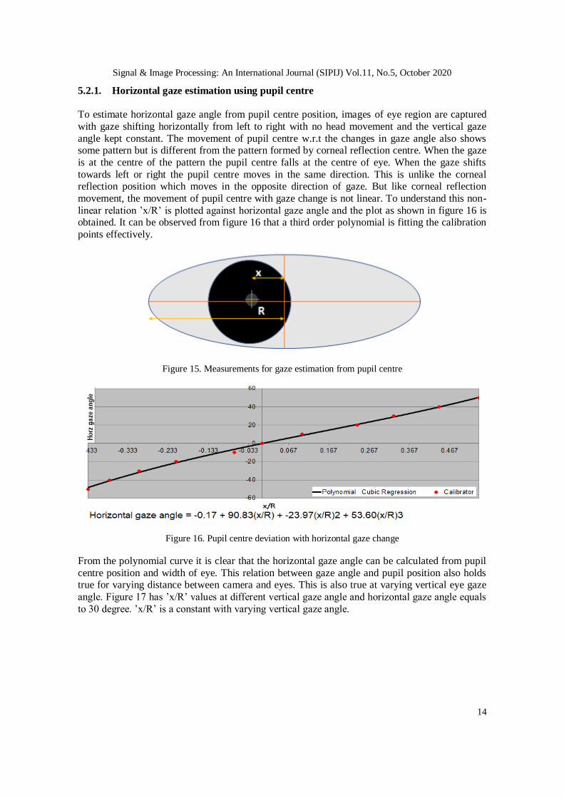
5.2.1. Horizontal gaze estimation using pupil centre
To estimate horizontal gaze angle from pupil centre position, images of eye region are captured
with gaze shifting horizontally from left to right with no head movement and the vertical gaze
angle kept constant. The movement of pupil centre w.r.t the changes in gaze angle also shows some pattern but is different from the pattern formed by corneal reflection centre. When the gaze
is at the centre of the pattern the pupil centre falls at the centre of eye. When the gaze shifts
towards left or right the pupil centre moves in the same direction. This is unlike the corneal reflection position which moves in the opposite direction of gaze. But like corneal reflection
movement, the movement of pupil centre with gaze change is not linear. To understand this non-
linear relation ’x/R’ is plotted against horizontal gaze angle and the plot as shown in figure 16 is obtained. It can be observed from figure 16 that a third order polynomial is fitting the calibration
points effectively.
Figure 15. Measurements for gaze estimation from pupil centre
Figure 16. Pupil centre deviation with horizontal gaze change
From the polynomial curve it is clear that the horizontal gaze angle can be calculated from pupil
centre position and width of eye. This relation between gaze angle and pupil position also holds true for varying distance between camera and eyes. This is also true at varying vertical eye gaze
angle. Figure 17 has ’x/R’ values at different vertical gaze angle and horizontal gaze angle equals
to 30 degree. ’x/R’ is a constant with varying vertical gaze angle.

Signal & Image Processing: An International Journal (SIPIJ) Vol.11, No.5, October 2020
15
Figure 17. x/R at varying vertical gaze angle
When the camera is not aligned with the centre of face, then there is a shift in the polynomial
curve from zero.
To check how generic is pupil centre-based gaze estimation method ’x/R’ values calculated from
multiple people are mixed and a third order polynomial curve is fitted on these calibration points.
Figure 18 has values from 3 different people marked in three different colours. The error in curve fitting is calculated and is found to be more when compared to the error obtained from the
corneal reflection-based method. Table 3 has values of coefficients and its error values.
The polynomial curve in figure 18 is used to estimate gaze for person 1,2 and 3 and the error in
gaze estimation is obtained as 3.72 degree, 4.61 degree and 4.88 degree respectively. The higher
error in the pupil-based approach is because of the variation in eye shape from person to person.
Figure 18. Pupil movement in different people
Table 3: Error values of polynomial coefficients
Coeff Value Error
a -2.21 2.67
b 83.01 10.41
c 12.54 14.43
d -7.14 43.20

Signal & Image Processing: An International Journal (SIPIJ) Vol.11, No.5, October 2020
16
5.2.2. Vertical Gaze Estimation using Pupil Centre
To estimate vertical gaze angle from pupil centre position, images of eye region are captured with
gaze shifting vertically and the horizontal gaze angle kept constant. Figure 19 is for vertical gaze angle equals 0,+10 and -10 degree and horizontal gaze angle kept as ’zero’. In all the three cases
the pupil centre is lying above the horizontal line connecting the eye corner points.
Figure 19. Pupil movement with vertical gaze change
In the case of Corneal reflection-based method, the target point is moving around the centre of
pupil in a defined pattern and the pupil centre point can be considered as a reference point. All
calculations to estimate eye gaze is independent of the width/height of the eye.
Whereas in the case of pupil centre-based method there is no fixed reference to estimate vertical
gaze angle and hence the estimation becomes difficult. The variation in eye shape from person to
person makes the gaze estimation challenging with pupil- based method.
6. MINIMUM GAZE ANGLE MEASURABLE
In driver monitoring systems it is important to correctly differentiate the gaze change while the
eye gaze is shifting between two points which are lying really closer. For example, to predict at which point on the infotainment cluster the driver is looking at, high precision gaze estimation
techniques are required. The difficulty in gaze estimation increases when the need for precise and
high-resolution gaze estimation is required. A comparative study is done on similar lines for pupil based and corneal reflection-based gaze estimation to find out which method is more efficient for
precise high-resolution gaze estimation. In order to perform this comparison a fixed pattern in
which the points are closely marked is placed in front of the person at 50cm distance from eyes and the gaze is varied horizontally between these closely marked points from left to right. Images
of resolution 1280 x 964 are captured using the IR camera. Deviation in corneal reflection centre
from pupil centre and pupil centre from eye centre has been measured in pixels for each of the
horizontal gaze angle. Table 4 contains the values, with the gaze changing from one point to next point with an offset of 1 degree.

Signal & Image Processing: An International Journal (SIPIJ) Vol.11, No.5, October 2020
17
Table 4: Deviation in pupil and corneal reflection with change in gaze
Horz gaze
angle
(degree)
CR
deviation
(pixels)
Pupil
deviation
(pixels)
Horz gaze
angle
(degree)
CR
deviation
(pixels)
Pupil
deviation
(pixels)
1 1 3 11 4 8
2 2 3 12 5 9
3 2 3 13 5 10
4 2 4 14 5 10
5 2 5 15 5 10
6 3 5 16 5 11
7 3 5 17 6 11
8 3 7 18 6 11
9 4 7 19 6 13
10 4 8 20 6 13
From the values shown in table 4 it can be inferred that the minimum gaze angle measurable with corneal reflection-based method is 4 degree and with pupil-based method is 3 degree for the
given image resolution and distance from the camera. The resolution at which the gaze angle can
be measured will always depend on the resolution of image captured. And for a given camera the
resolution of gaze estimation depends on the distance of the camera from the eyes. With the increase in image resolution or with the camera placed more closer to the eyes, the gaze
estimation resolution can be improved.
The values for minimum gaze change measurable has been extended to an in-vehicle
environment with the driver eye at a distance of 50cm from the dashboard as shown in figure 20.
The gaze plain covers the instrument cluster and infotainment cluster. Using the minimum
measurable gaze change value calculated as 3 degree and 4 degree for pupil and corneal reflection-based methods, a set of distinguishable gaze points are marked on the gaze plain as
shown in figure 21.
Figure 20: Minimum gaze angle measurable inside a car

Signal & Image Processing: An International Journal (SIPIJ) Vol.11, No.5, October 2020
18
Figure 21: Minimum gaze angle measurable inside a car
From figure 21 it can be observed that between 0 degree to 36 degree gaze change there are more distinguishable gaze change points with pupil based method (13 points) than with CR based
method(10 points).
7. CONCLUSIONS Various aspects of eye gaze estimation for driver monitoring systems are studied. Safe and unsafe
gaze zones and the typical gaze timings are analysed. Clear demarcation of on road and off-road
points helps in proper eyes off the road (EOR) detection that can enable triggering of appropriate warnings or alerts. Comfortable gaze zones and the need to incorporate head orientation in gaze
estimation is studied. The comparison of sensor types and sensor placement shows the different
options that are available. The right choice would depend upon the specific use case that would
need the images to be processed. From the comparison on gaze estimation methods it is understood that the pupil-based method has few limitations but it can work with any camera
which can capture image of eye region clearly. Pupil based method doesn’t need any IR
illuminators and uses only eye features for gaze estimation. The corneal reflection method has few advantages, but it requires infra-red illuminators to illuminate the eyes for forming the bright
spot on cornea. On the other hand, using IR camera and IR illuminators is useful in low light or
dark scenarios like in driver monitoring systems. From the analysis done on the resolution of gaze estimation it is observed that pupil- based method has better gaze resolution than corneal
reflection-based method with the given camera setup.
ACKNOWLEDGEMENTS The authors would like to thank people who supported in data collection.

Signal & Image Processing: An International Journal (SIPIJ) Vol.11, No.5, October 2020
19
REFERENCES [1] Wang, Y.; Yuan, G.; Mi, Z.; Peng, J.; Ding, X.; Liang, Z.; Fu, X. Continuous Driver’s Gaze Zone
Estimation Using RGB-D Camera. Sensors 2019, 19, 1287.
[2] A. Kar and P. Corcoran, "A Review and Analysis of Eye-Gaze Estimation Systems, Algorithms and
Performance Evaluation Methods in Consumer Platforms," in IEEE Access, vol. 5, pp. 16495-16519,
2017, doi: 10.1109/ACCESS.2017.2735633.
[3] B. Vasli, S. Martin and M. M. Trivedi, "On driver gaze estimation: Explorations and fusion of
geometric and data driven approaches," 2016 IEEE 19th International Conference on Intelligent Transportation Systems (ITSC), Rio de Janeiro, 2016, pp. 655-660, doi:
10.1109/ITSC.2016.7795623.
[4] H. S. Yoon and K. R. Park, "CycleGAN-Based Deblurring for Gaze Tracking in Vehicle
Environments," in IEEE Access, vol. 8, pp. 137418-137437, 2020, doi:
10.1109/ACCESS.2020.3012191.
[5] Aditya Hosamani and Manoj Phirke. 2020. Real-time head pose estimation based on face geometry.
In Proceedings of the 5th International Conference on Multimedia and Image Processing (ICMIP '20).
Association for Computing Machinery, New York, NY, USA, 38–42.
[6] J. Sigut and S. Sidha, ”Iris Center Corneal Reflection Method for Gaze Tracking Using Visible
Light,” in IEEE Transactions on Biomedical Engineering, vol. 58, no. 2, pp. 411-419, Feb. 2011.
[7] Sesma-Sanchez, Laura. (2016). Gaussian processes as an alternative to polynomial gaze estimation
functions. 10.1145/2857491.2857509. [8] Chennamma, Hr & Yuan, Xiaohui. (2013). A Survey on Eye-Gaze Tracking Techniques. Indian
Journal of Computer Science and Engineering. 4.
[9] Morimoto, Carlos& Mimica, Marcio. (2005). Eye gaze tracking techniques for interactive
applications. Computer Vision and Image Understanding. 98. 4-24. 10.1016/j.cviu.2004.07.010.
[10] D. W. Hansen, Q. Ji, ”In the eye of the beholder: A survey of models for eyes and gaze”, IEEE Trans.
Pattern Anal. Mach. Intell., vol. 32, no. 3, pp. 478-500, Mar. 2010.
[11] Chunfei Ma, Seung-Jin Baek, Kang-A Choi, Sung-Jea Ko, ”Improved remote gaze estimation using
corneal reflection-adaptive geometric transforms,” Opt. Eng. 53(5) 053112 (14 May 2014).
[12] Cazzato, D.; Leo, M.; Distante, C. An Investigation on the Feasibility of Uncalibrated and
Unconstrained Gaze Tracking for Human Assistive Applications by Using Head Pose Estimation.
Sensors 2014, 14, 8363- 8379. [13] Gneo, M., Schmid, M., Conforto, S. et al. A free geometry modelindependent neural eye-gaze
tracking system. J NeuroEngineering Rehabil 9, 82 (2012). https://doi.org/10.1186/1743-0003-9-82.
[14] Lin, Y., Lin, R., Lin, Y. et al. Real-time eye-gaze estimation using a low-resolution webcam.
Multimed Tools Appl 65, 543–568 (2013).
[15] Ince, I.F., Kim, J.W. A 2D eye gaze estimation system with lowresolution webcam images.
EURASIP J. Adv. Signal Process. 2011, 40 (2011).
[16] Wen Zhang, Tai-Ning Zhang, Sheng-Jiang Chang,” Eye gaze estimation from the elliptical features
of one iris,” Opt. Eng. 50(4) 047003 (1 April 2011).
[17] Brisson, J., Mainville, M., Mailloux, D. et al. Pupil diameter measurement errors as a function of gaze
direction in corneal reflection eyetrackers. Behav Res 45, 1322–1331 (2013).
[18] M. S. Mounica, M. Manvita, C. Jyotsna and J. Amudha, "Low Cost Eye Gaze Tracker Using Web
Camera," 2019 3rd International Conference on Computing Methodologies and Communication (ICCMC), Erode, India, 2019, pp. 79-85, doi: 10.1109/ICCMC.2019.8819645.
[19] Brunyé, T.T., Drew, T., Weaver, D.L. et al, "A review of eye tracking for understanding and
improving diagnostic interpretation", Cogn. Research 4, 7 (2019).
[20] Ashraf, H., Sodergren, M. H., Merali, N., Mylonas, G., Singh, H., & Darzi, A. (2018). Eye-tracking
technology in medical education: a systematic review. Medical Teacher, 40(1), 62–69.
[21] A. Kar and P. Corcoran, "A Review and Analysis of Eye-Gaze Estimation Systems, Algorithms and
Performance Evaluation Methods in Consumer Platforms," in IEEE Access, vol. 5, pp. 16495-16519,
2017, doi: 10.1109/ACCESS.2017.2735633.
[22] J. Lemley, A. Kar, A. Drimbarean and P. Corcoran, "Convolutional Neural Network Implementation
for Eye-Gaze Estimation on Low-Quality Consumer Imaging Systems," in IEEE Transactions on
Consumer Electronics, vol. 65, no. 2, pp. 179-187, May 2019, doi: 10.1109/TCE.2019.2899869.

Signal & Image Processing: An International Journal (SIPIJ) Vol.11, No.5, October 2020
20
AUTHORS
Susmitha Mohan is a Lead engineer who has experience in developing various imaging
and machine learning based solutions for automotive, aerospace and other domains.
Worked in algorithm development from scratch, integrating components, testing and
validating components as well as solutions, designing and modularization of algorithms.
Worked closely with cross-functional teams like testing and validation, hardware
porting, on road testing, data collection etc.
Manoj is an Imaging/Computer vision architectwith wide experience in end to end
product development including video/image processing, enhancement, view transformations, segmentation, object detection, recognition, tracking etc. Developed
and managed solutions across multiple verticals like avionics, automotive, printing and
document imaging, security and surveillance, manufacturing. Co-authored 3 USA
patents granted for Automotive Driver Assistance Systems.