Embed Size (px)
Citation preview

Lightweight ForgingPotential of Forged Components


3
Foreword
The demands placed on all technologies of automotive
manufacture are clearly defined by the legislative au-
thority. Strict EU emission requirements are prompting
manufacturers to more than double the share of light-
weight components in their vehicles over the next two
decades.
This is a goal that is especially directed at suppliers to
the industry. Due to their particular strengths, forging
companies in Germany have been an important innova-
tive partner to automotive manufacturers for decades.
These strengths lie in the development and production
of highly stressed parts as well as in exhausting all the
possibilities offered by materials to find the optimum
one for the particular process. Mainly these materials
are steels.
Faced with this challenge and given the pioneering
results of several lightweight design projects between
1994 and 2002 which primarily focussed on the area
of the vehicle body, The Lightweight Forging Initiative
was created in February 2013. Nine companies from
the steel industry as manufacturers of wire and bar
joined forces with 15 forging companies under the
auspices of the German Forging Association (Industrie-
verband Massivumformung e. V.) to form the Initiative.
This cross-company and cross-sector consortium brings
together know-how from materials science and forging
technology, allowing the participating companies to
transfer the insights they gain into the parts supplied to
the automotive industry.
In an initial study carried out during three workshops,
the potential of forget parts for generating weight
savings was demonstrated on a middle-class vehicle.
The analysis focused in particular on the powertrain
and chassis. The 400 ideas derived from this then
underwent a feasibility check.
This EXTRA-Info will report on the motivational factors
of this pre-competitive consortium and will primarily
focus on the procedure and the results obtained from the
joint research into automotive weight-savings potential.
As know-how from the areas of steel manufacture and
processing were brought together in the Initiative, op-
timization proposals could be examined from all angles.
Based on the lightweight design potential which has
already come to light, it would make sense to continue
the analyses and to extend them to encompass other
vehicle classes. At the same time, the results reveal that
there is a considerable need for research. This require-
ment has already been addressed with the submission of
a comprehensive research proposal.
With this latest issue of our EXTRA-Info series, we are
pleased to provide effective support on all issues of
modern, innovative products and processes to all those
interested and involved in the development of “Light-
weight Design with Forging”. We hope this publication
will be used actively and find diverse application.
Dr.-Ing. Hans-Joachim Wieland
Managing Director
Steel Institute VDEh
Research Association for Steel Application
(Forschungsvereinigung Stahlanwendung e. V. FOSTA)
40237 Düsseldorf
Dr. Theodor L. Tutmann
Managing Director
German Forging Association
(Industrieverband Massivumformung e. V.)
58093 Hagen, April 2014

4
Imprint
Author: Dipl.-Ing. Frank Severin, Bochum
Basis of this document: Dipl.-Ing. Dipl.-Wirt. Ing. Christian-Simon Ernst,
fka Forschungsgesellschaft Kraftfahrwesen mbH Aachen
Dr.-Ing. Hans-Willi Raedt, Hirschvogel Automotive Group, Denklingen
Dipl.-Ing. Frank Wilke, Deutsche Edelstahlwerke GmbH, Siegen
Images: See List of Figures Page 41
Responsible for
overall production: German Forging Association (Industrieverband Massivumformung e. V.), Hagen,
Dorothea Bachmann Osenberg
www.massivumformung.de / www.massiverLEICHTBAU.de
Layout and Cover Page: simplon., Advertising Agency, St. Ingbert
Translation: Sarah Cory-Raedt B. A. (Hons.), Buchloe
Publication No.: El-LB-e-0414-05
Issue: April 2014
ISBN: 978-3-928726-34-4
This publication is protected by copyright. All rights reserved, including the right of translation and reproduction.
Reproduction of the contents in part only with permission from the German Forging Association (Industrieverband
Massivumformung e. V.) and with an indication of source. The publications of the German Forging Association
are based on the results of the joint research of the consortium of companies in the German Forging Association.

5
Forging Industry Information Service, Special Edition
Publisher:
Industrieverband
Massivumformung e. V.
Goldene Pforte 1
58093 Hagen, Germany
Tel.: + 49 2331 958830
Fax: + 49 2331 958730
E-mail: [email protected]
www.massivumformung.de
www.massiverLEICHTBAU.de
Lightweight ForgingPotential of Forged Components

6

7
Page
Foreword 3
Imprint 4
1 Introduction 9
1.1 Trends and Driving Forces for Automotive Lightweight Design 9
1.2 Motivation for The Lightweight Forging Initiative 10
1.3 Selection of Lightweight Design Innovations in Forging 12
2 Lightweight Design Potential of Forged Components in Passenger Cars 15
2.1 Conducting the Study on Lightweight Design Potential 15
2.1.1 Procedure and Steps 15
2.1.2 Assessment of the Study on Lightweight Design Potential 15
2.2 Examples of Identified Lightweight Design Potential 22
2.2.1 Material Lightweight Design Potential 23
2.2.2 Lightweight Potential through Structural Design and Manufacture 25
2.2.3 Conceptual Lightweight Design Potential 30
2.3 Summary and Conclusion 30
3 Transfer of Insights to Development Processes and Research Projects 32
3.1 Transfer of Insights to Development Processes 32
3.2 Research Approaches 32
4 Additional Lightweight Design Potential with Forging 33
5 Summary and Outlook 36
6 List of References 39
7 List of Figures 41
Contents

8

9
Introduction
“Lightweight Forging” – at fi rst, this appears to be a
paradox. After all, in contrast to sheet-metal forming,
forging is a “bulk” or “massive” metal forming process,
where the starting material is in the form of billet, rod or
slab. The terms “bulk” and “massive” are generally as-
sociated with synonyms such as “solid” and “dense” in
contrast to “hollow”, and thus imply “heavy” or “weighty”.
The meaningfulness of the description “Lightweight
Forging” becomes clear, however, if technically more
appropriate synonyms such as “strong”, “durable” and
“resilient” are used or other more common terms such
as “tough” and “effective”.
“Lightweight forging” represents the strive towards de-
signing mobility technology in a sustainable and lasting
way and expresses the goal of fi nding a technical solu-
tion with minimum mass utilization.
This is particularly important if these masses need to be
driven, i. e. when the task of technical components is
to achieve mobility. Human physical strength for driving
mobile technical devices is so limited that motorized
drives need to be employed in almost all cases. On the
one hand, this renders the burning of fossil fuels neces-
sary for energy provision or generation. On the other
hand, it leads to the emission of greenhouse gases into
the environment.
It was from mankind’s high demand for mobility that
automotive technology emerged more than 100 years
ago. The automotive industry relies on steel manufac-
turers for high-quality materials and on forging com-
panies, with their numerous and diverse processes, for
important parts and components. Effective lightweight
design achieved through “massive” forming, i. e. for-
ging, has thus arisen from a megatrend of automotive
engineering.
1.1 Trends and Driving Forces
for Automotive Lightweight
Design
Since the beginning of car mobility, the strive towards
individual motorized travel among the global popula-
tion has grown inversely proportional to the earth’s re-
sources of the fossil fuels required for this. At the same
time, the increasing demands placed on vehicles with
respect to comfort and safety have given rise to signifi -
cantly higher overall vehicle weights.
Particularly worthy of mention in this context is the im-
provement of driving dynamics through continuously
optimized braking and accelerating properties, as well
1
Figure1: CO2 targets for European new car fl eet from 2012 to 2021
2012 2013 2014 2015 2020 2021
Time
Targ
etv
alues
fo
rth
eC
O2fl
eet
em
issi
on
so
fth
eEU
/g
/km
10 g/km through other technical measures
95 g/km
From2015to2021reductionFrom2015to2021reductionFrom2015to2021reduction
by5.8g/kmperyearby5.8g/kmperyearby5.8g/kmperyear
65 % 75 % 80 % 100 %
100 %95 %
130 g/km

10
as the reduction of purchasing and operating costs [1].
Furthermore, secondary lightweight design potential is
being addressed, which can be scaled through reduced
vehicle mass. This affects the areas of the drive, brakes
and suspension (i. e. chassis) and amounts to 30 % of
the primary potential.
However, it is ultimately the legislative authority which
is formulating an ambitious challenge. What is being
referred to here is the European Union legislation regard-
ing the reduction of CO2 emissions, in particular the re-
gulation for reducing CO2 emissions in cars, which came
into force in 2009. Under this regulation, automotive
manufacturers are obliged to limit the emission values
of all new vehicles to a threshold value of 130 g/km
by 2015 and to 95 g/km by 2021. The phase-in values
which are valid prior to 2015 are shown in Figure 1 [2].
The technical measures leading to lower consumption
and thus to a reduction in emission volumes are nu-
merous. Forged components can support engineering
developments here in the areas of combustion engine,
transmission and, above all, lightweight design, there-
by contributing to desired technical advancements [3].
In other words, forging companies already hold the
answers to these megatrends.
1.2 Motivation for The Lightweight Forging Initiative
The graphical representation of the “Weight Spiral” (Fig-
ure. 2) illustrates the necessity for switching from an
upward to a downward movement, and is explained in
more detail in [4].
The left side of the graph reveals the situation over the
past decades: Increasing demands placed on the parame-
ters shown led to an increase in weight of the car body.
As a result, the chassis, powertrain and also components
such as the tank were strengthened or enlarged. This in
turn meant that the car body needed to be modifi ed, and
so manufacturers became caught up in the spiral.
The break in this spiral only succeeded with the use of
lightweight design potential in the car body. This so-
lution approach from vehicle manufacturers shown on
the right half of the graph opens up scope for suppliers
focussing on the powertrain and chassis.
Accordingly, automotive lightweight design has con-
centrated very much on sheet-metal forming and the
car body to date. This may be seen from the most im-
portant major lightweight design projects from various
initiators (steel industry, individual steel manufacturers
1
Figure2: Reversal of the Weight Spiral through lightweight design in the powertrain und chassis
IncreasingDemands: CarManufacturers:
• Integrated vehicle concepts • Focus on carbody
•Top-Down approach
Suppliers:
• Component and production know-how • Focus onpowertrainandchassis
•Bottom-Upapproach
Safety + kg
Comfort + kg
Drivingperformance + kg
Space + kg
Variability + kg
Quality + kg
WeightSpiral
Lösu
ng
san
satz
Common goal:
Weightreduction

11
or suppliers, OEMs) which are summarized in a chrono-
logical overview in Figure 3.
It is evident that the current potential of the car body
as the largest constituent element of vehicle weight has
been largely tapped using modern material and process-
ing concepts. Instead, attention is now turning to the
powertrain and chassis, which together make up an
average of 41 % of the vehicle weight [5].
A considerable motivating factor in forming the in-
dus-try initiative comprising steel manufacturers and
forging companies was thus given: The Lightweight
Forging Initiative [6] was created at the beginning of
2013, bringing together 15 forging companies and 9
steel manufacturers under the auspices of the German
Forging Association and the Steel Institute VDEh. Wi-
thout drawing on public funding, this consortium is
fi nancing the study “Lightweight Design Potential of
Forged Components in Passenger Cars”, which is outli-
ned in more detail in Chapter 2. The goal of the study
is to optimize forged steel components in the car with
respect to lightweight design. The Lightweight Forging
Initiative is by far the largest pre-competitive joint pro-
ject of these two industries to date.
The idea originated back in 2011 based on the convic-
tion that individual companies certainly cannot achieve
the broad level of ingenuity and creativity that is
possible as part of a cooperation. Many automotive man-
ufacturers seemed to be interested primarily in recent
manufacturing processes and technologies, paying little
attention to the development of proven processes. The
Lightweight Forging Initiative, as a cross-sector project,
brings together concentrated know-how from materi-
als science and forging technology – and this was to
be the decisive multiplier. From the viewpoint of the
steel manufacturers, it seemed highly important to al-
low advancing materials development to fl ow into end
products. In this way, the automotive industry would
optimally exploit modern high-strength steels and be
able to generate new application possibilities which
fulfi l economic and ecological considerations [7]. By
pooling competence and know-how, an integrated
optimization approach is possible, ranging from steel
composition to the production of ready-for-assembly
components.
The Lightweight Forging Initiative was created to high-
light to the professional world the contributions which
forging makes to the automotive megatrend of light-
weight design. Furthermore, through timely and targe-
1
Figure3: Overview of some important lightweight projects in the automotive environment (1994 to 2013)
Project Year 94 95 96 97 98 99 00 01 02 03 04 05 06 07 08 09 10 11 12 13 Consortium(Lead)
ULSABUltraLight Steel Auto Body
WorldAutoSteel
ULSASUltraLight Steel Auto Suspension
WorldAutoSteel
ULSACUltraLight Steel Auto Closures
WorldAutoSteel
ULSAB-AVCUltraLight Steel Auto Body – Advanced Vehicle Technology
WorldAutoSteel
NewSteelBody TKS
SuperLIGHT-CarSustainable Production Technologies for CO2 emissions Reduced Lightweight Car concepts
EUCAR
InCarInnovative Car
TKS
FutureSteelVehicle WorldAutoSteel
LDVMassReductionLight-Duty Vehicle Mass Reduction and Cost Analysis – Midsize Crossover Utility Vehicle
FEV / EDAG
CULTCars’ Ultralight Technologies
Magna

12
ted dialogue between steel and component suppliers
on the one hand and automotive customers on the
other, the potential should be incorporated at the early
stages of system and part development. At the same
time, it is important to use proven methods of simulta-
neous engineering to initiate new solution approaches
from conceptual lightweight design.
1.3 Selection of Lightweight
Design Innovations in Forging
The possibilities and physical-technological correlations
in the various disciplines of lightweight design through
forging, which may be subdivided into the areas of
material lightweight design potential (material require-
ments), lightweight potential through structural design
(topology and design optimization) and lightweight
design potential through manufacturing measures (fi -
bre fl ow, surface treatment processes), are described in
detail in [8] and [9], among others. For this reason, the
following will present a selection of innovative solutions
without any claim to completeness, offering a basic
overview of lightweight design solutions already imple-
mented in series.
In the area of material lightweight design in the chas-
sis, substituting steel components with parts made of
aluminium is already a well established approach. An
example of this is the car rear-axle wheel carrier shown
in Figure 5, which underwent signifi cant reworking as
part of a change in model. Through improved design
as an aluminium forging as well as a modifi ed bearing
generation, the system weight was reduced by 1.8 kg.
Although part of this weight reduction is thus not at-
tributable to the change in material, the potential of
forging is nevertheless clear [10].
Aluminium forged parts are also used in other applica-
tions besides cars. Through optimizations with respect
to design and requirements, they also fi nd application
in motorcycles, as the trailing link in Figure 6 shows
[11]. It was thought in the past that the fi ligree design
of this part could not be produced by means of forging.
It is clear from the above-mentioned examples that the
geometry and the assembly space of a component like-
wise play a decisive role. Experience also shows that ap-
parently simple tasks in the area of material lightweight
design very often require comprehensive design modi-
fi cations. In such cases, it becomes clear that substitut-
ing materials in favour of “lighter” ones is not more
effective than retaining the existing material group and
perfecting part geometry through structural design or
optimizing the manufacturing process [12].
This insight leads both to design and production solu-
tions in forging, such as hollow shafts. Particularly in
1
Figure4: Logo of The Lightweight Forging Initiative
Figure5: Car rear-axle wheel carrier – left: steel, right: next
generation made of aluminium with reduced system weight
Figure6: Motorcycle trailing link as an aluminium forging

13
the area of transmissions, hollow shafts are gaining in
importance. This is due to technical necessity, such as in
double-clutch transmissions, or in some electrical drive
concepts. Furthermore, a hollow transmission shaft has
the required lightweight design potential, as the neces-
sary torsional stiffness, among other things, is barely
affected by the core of the shaft. These savings can
thus be achieved here by reducing non-load-bearing
cross sections. Figure 7 shows hollow shaft forgings for
transmission shafts. These were produced by means of
a multiple-stage cold forging process combined with
machining. The weight savings amount to 27 % and
38 % [10], [13].
In view of the diverse forging production technologies,
several other hollow lightweight shafts are possi-
ble using the processes of swaging and extrusion. The
application area ranges from hollow steering shafts
(Figure 8) to hollow transmission and input shafts as
well as shock absorber elements. With this production
technology, extremely high surface qualities can be gen-
erated, often rendering subsequent machining opera-
tions unnecessary. This is achieved through incremental
forging with a very high stroke frequency at very low
deformation per stroke. The high level of strain that
is possible with swaging allows great design diversity.
With forward extrusion, stable and precision-quality
splines can be produced, which are often also required
on a shaft [14].
There are two other established principles for light-
weight design in forging which are worthy of mention:
functional integration and the assembled component.
An example of the functional integration of parts that
were previously forged separately is a truck steering
knuckle and the associated wishbone, which are merged
into an integral forging following thorough FE analysis
[15].
The opposite route may be taken by an assembled
camshaft, for example. Here, instead of forging the raw
part in one piece as is customary, the actual shaft is de-
signed as tubing and the cams are produced separately
as a forged part. In this case, the most cost-effi cient
form of production is on fully automatic horizontal multi-
stage presses, which generate the cams with a rapid
cycle frequency at consistently high quality.
With this wealth of experience and the potential it
holds, the participants of The Lightweight Forging Initia-
tive entered their fi rst major project phase with a study
on lightweight design potential. The results of this will
be presented in the next chapter.
1
Figure7: Forgings for hollow transmission shafts, left 27 %
and right 38 % weight reduction
Figure8: Examples of hollow swaged steering shafts

14

15
Lightweight Design Potential of Forged Components in Passenger Cars
2.1 Conducting the Study on
Lightweight Design Potential
2.1.1 ProcedureandSteps
During an initial step, The Lightweight Forging Initia-
tive conducted a study on lightweight design potential,
which took the form of several workshops between Feb-
ruary and October 2013. The basis of these workshops
was a methodical approach consisting of five successive
working points. The project activities are shown in Fig-
ure 9.
Firstly, a systematic overview of lightweight design po-
tential was generated for the powertrain and chassis
of a passenger car. This was based on research results
and projects from this area published to date as well
as on an analysis of accepted lightweight design costs
per vehicle.
Following this, the second step involved benchmarking.
Here, a car with only low mileage was procured as a
reference vehicle and systematically disassembled by
the automotive engineering institute, fka Forschungs-
gesellschaft Kraftfahrwesen mbH Aachen, which was
commissioned to carry out the study. The reference
vehicle selected was a middle class estate car from a
German manufacturer with significant series volume, a
diesel engine with double-clutch transmission as well
as all-wheel drive. During disassembly of the entire
vehicle, parts were classified according to the decisive
categories of the study, namely the powertrain, i. e. en-
gine and transmission, as well as the chassis and other
components.
All assemblies and individual parts were analysed, with
parameters relating to dimension, material and of
course weight being stored in an online database. To
determine the material, analysis was also carried out
in the materials laboratory, where necessary. Further-
more, another important aid was comprehensive photo
documentation, which is complemented by assembly
drawings from the manufacturer.
Three facilitated hands-on workshops on the vehicle
areas of powertrain, chassis and other components
formed the focus of the study. Here, experts from the
development and production departments of the par-
ticipating companies came together to examine the
parts following pre-evaluation carried out by the fka,
as well as to develop and formulate lightweight design
ideas. Impressions from the workshops are shown in
Figure 10.
In all the workshops, the participants needed to work
on lightweight design proposals by sketching and / or
describing their idea as well as by carrying out their
own assessment in the three categories of lightweight
design potential, cost potential and implementation ef-
fort. This was necessary to achieve a multidimensional
evaluation. All the aforementioned information was
noted on lightweight design ideas sheets, which served
as a basis for entries into the database. The set up and
maintenance of the online database is an important ac-
companying working step alongside recording and pre-
senting results as well as visualizing them for later use
at other events of The Lightweight Forging Initiative.
In a final working point, the lightweight design poten-
tial of forged components in a car was identified by
elaborating the ideas into lightweight design proposals
using initial CAD designs or by approximate load cal-
culations.
Examples of concrete lightweight design proposals ob-
tained during this phase of the study are outlined in the
Chapter 2.2.
2.1.2 AssessmentoftheStudy
onLightweightDesignPotential
The systematic disassembly of the reference vehicle
uncovered approximately 3,500 parts for analysis. The
analysis led to the formation of 399 lightweight design
ideas, which were formulated in the three workshops
by a total of 65 different people from 30 companies
and research institutes. In total, 123 people took part in
the workshops [1].
2

16
Figure9: Project procedure for the study on lightweight design potential
ContextAnalysis
A systematic overview of previous lightweight design potential in the powertrain
and chassis is available.
Benchmarking
A reference vehicle was systematically disassembled, documented and recorded.
ThreeHands-onWorkshops
Facilitated workshops were held on the drive, chassis and other components.
Gatheringideasandderivinglightweightdesignpotentialfromthese
Previously unknown lightweight design potential has been identifi ed on forged
components in a car and translated into concrete lightweight design proposals.
1.Determiningthetotalvehicleweight1.Determiningthetotalvehicleweight1.Determiningthetotalvehicleweight
2.Disassemblingtheentirevehicle2.Disassemblingtheentirevehicle2.Disassemblingtheentirevehicle
3.Listingandnamingallindividualparts3.Listingandnamingallindividualparts3.Listingandnamingallindividualparts
4.Analysisofindividualparts4.Analysisofindividualparts4.Analysisofindividualparts
5.Weightofassemblies5.Weightofassemblies5.Weightofassemblies
6.PhotoDocumentation6.PhotoDocumentation6.PhotoDocumentation
7.Databaseimplementationwith7.Databaseimplementationwith7.Databaseimplementationwithproposalsforlightweightdesignpotentialproposalsforlightweightdesignpotentialproposalsforlightweightdesignpotential
Combustion engine
Door, seat, seatbelt, tow coupling
Transmis-sion
Chassis
Parkinggear
(22108020001)
Referencevehicle: 125 kw / 170 PS
2.0 l Turbo-DI diesel engineDouble-clutch transmission, all-wheel driveTotal mass: 1,740 kg
● ISO views ● Detailed views ● Installation positions,
where necessary ● Digital removal of
manufacturer logo
2

17
It makes sense to limit the description of the weight
assessment of the reference vehicle to the overall evalu-
ation as well as to the share of forged components. The
vehicle under analysis has a total weight of 1,740 kg.
As shown in Figure 11, the weight assessment subdi-
vides the total weight into components from the car
body (39 %), powertrain (23 %), chassis (16 %), interior
(16 %) and electronics (6 %).
As it is primarily powertrain and chassis components
which are of interest for lightweight design ideas using
forging, all of the parts assigned to these categories
underwent assessment in each case. In addition, 19 %
of the interior (front seats and belt system) as well as
15 % of the car body (front doors and front bumper
system as well as fastening elements) were included in
the analysis.
This represents exactly 838 kg in mass or approximately
48 % of the whole car.
In a detailed weight assessment of the powertrain, it is
no surprise to fi nd that the combustion engine domi-
nates with a 59 % share. The torque converter (double-
clutch transmission) contributes to 16 % of the weight,
just like the differential and transfer gearbox. The re-
maining 9 % comes from the four drive shafts (Fig-
ure 12, above).
Figure10: Project participants and presentation of the components from the disassembled reference car during one of the three
hands-on workshops
Figure11: Weight of the reference vehicle
Focusofanalysis: 838kgTotal weight: 1,740 kg
Interior
Electronics
Car body
Chassis
Powertrain
2
16%19 %
of this analysed
23%25.5kg
258ideas
16%13.5kg
133ideas
39%15 %
of this analysed 6%
ReferenceVehicle125 kW / 170 PS
2.0 l Turbo-DI Diesel engineDouble-clutch transmission
All-wheel drive
3.0kg8ideas

18
Figure12: Weight of the powertrain and chassis
Combustionengine
Torqueconverter
Differentialandtransfergearbox
Inputshafts
Frontaxle
Rearaxle
Wheelsandtyres
Brakingsystem
Steeringsystem
399.45kg
284.50kg
9%
59%
22%
18%
8%
21%
31%
16%
16%
WeightofthePowertrain
WeightofChassis
By contrast, the assessment of chassis weight reveals
a more even distribution. Wheels and tyres make up
31 %, the front axle 18 % and the rear axle 22 %. The
brake system contributes to 21 %, while the steering
system is responsible for the remaining 8 % (Figure 12,
below).
The results of the pre-evaluation carried out in advance
of the workshops are shown in Figure 13. Here, it is
clear that some weighty vehicle components cannot
even be considered for a lightweight design potential
analysis, as it is not possible for technical or economic
reasons to produce them by means of forging. These
components include the engine block, exhaust system
and rear subframe. The remaining components from
the powertrain and chassis are classifi ed as
• wire and bar products,
• potential for forging,
• forged and
• fastening elements (“nuts and bolts”).
Figure 14 provides a basic overview of the distribution
of lightweight design ideas submitted and the light-
weight design potential determined for the areas of
powertrain, chassis and other components. Overall, a
weight savings potential of 42 kg was identifi ed, which
corresponds to an astounding share of over 5 % of the
total mass of 838 kg under analysis.
2

19
In order to prioritize these ideas, two portfolios were set
up for classifying the assessment of lightweight design
proposals from the workshops on the powertrain and
chassis, and for providing a very good visual aid. Here, the
cost potential is plotted against the lightweight design
potential. In addition, the estimated implementation
effort is distinguished using different colours. Figure 15
and Figure 16 show two portfolio graphs. It should be
noted that the values of the lightweight design poten-
tial are appropriately represented on the Y-axis in relation
Figure13: Percentage of forged components
Figure14: Evaluation and savings potential of the 399 ideas
Powertrain 258ideas
Chassis 133ideas
Othercomponents 8ideas
Weightsaving 399ideas
-25.5kg
-13.5kg
-3.0kg
42 kg
Forged Potentialforforging
Barandwireproducts
Notforged(withoutpotential)
Powertrain(information in %)
Chassis(information in %)
Total(information in %)
Examples:
Screwcylinderhead0.109 kg (10x)
Screwsubframe0.1267 kg (4x)
Screwtransmission0.0247 kg (19x)
Crankshaft13.9 kg
Inputshaftdifferential3.42 kg
Wheelbearing(part1)1.74 kg (4x)
Wheelrim10.66 kg (4x)
Wheelcarrierrear2.84 kg (2x)
Differentialcarrier4.18 kg
Frontstabilizer4.32 kg
Inputshaftrear2.52 kg (2x)
Springshockabsorberfront2.16 kg (2x)
Engineblock40.3 kg
Exhaustsystem(part2)18.5 kg
Subframerear17.06 kg
399.45kg 284.50kg 683.95kg
27
1321
933 19
46 5
3 3 3
56
45
51
2
Nutsandbolts

20
to the original value of “component weight” and that in
most cases, one symbol represents between 5 and 36
lightweight design proposals.
Additional portfolio graphs in this form for the other
components are not included here, as the focus of the
analyses is on the areas of powertrain and chassis.
The prioritization shows that it is possible to make a
classifi cation according to groups: Group A represents
the optimum between potential and costs. According
to the estimation of the experts, both weight reduction
and cost decreases are possible here. These ideas are
thus “quick wins”. Measures from Group E, by con-
trast, are apportioned to the area of full utilization of
lightweight design potential, as the implementation ef-
fort on the development side is deemed to be generally
more cost-intensive.
The cumulative graph in Figure 17 shows the overall
result: The quick wins mentioned above represent cost-
effi cient lightweight design. A high implementation
potential in the high series volume segment already
results in a saving of approximately 25 kg. With the
savings potential of up to 42 kg, full utilization of the
lightweight design potential is depicted. By means of
forging, it is thus possible through signifi cant savings
to reduce the analysed share of 838 kg of the vehicle
weight to a remaining 796 kg.
Another representation of the lightweight design ideas
is categorized according to:
• material lightweight design / alternative material use,
• lightweight potential through structural design and
manufacture as well as
• conceptual lightweight design
This categorization is shown in Figure 18.
Figure15: Portfolio for prioritizing lightweight design ideas in the powertrain
Optimum
Con
stan
tLi
gh
twei
gh
tD
esig
nP
ote
nti
alH
igh
(-30
%)
More expensive CostPotential Less expensive
Implementationeffort: Low Medium High
GroupA-13.58kg
GroupB-0.21kg
GroupC-3.82kg
GroupD-4.96kg
GroupE-3.01kg
2

21
Figure16: Portfolio for prioritizing lightweight design ideas in the chassis
Optimum
Con
stan
tLi
gh
twei
gh
tD
esig
nP
ote
nti
alH
igh
(-30
%)
More expensive CostPotential Less expensive
Implementationeffort: Low Medium High
GroupA
GroupB
GroupC
GroupD
GroupE
Figure17: Cumulative representation of the lightweight design potential following prioritization
840
830
820
810
800
430
0
838kg
Starting weight
-17kg
-25kg
-42kgFullutilizationoflightweightdesignpotential
Wei
gh
t/
kg
Optimum between lightweight design
and costs
Combination of lightweight design potential and costs
Constant costs and medium lightweight
design potential
Expanded lightweight design
potential
Full utilization of lightweight design
potential
Lightweight design
with forging
-15.7kg -16.6kg -25.5kg -38.6kg -42.0kg
Chassis285kg
Power-train
399kg
Other154kg
Cost-efficientlightweightdesign
Highimplementationpotentialforvolumesegment
796kg
2

22
As can be seen, approximately 33 % of the lightweight
design ideas are attributed to material lightweight
design (Chapter 2.2.1) which, depending on the part,
may demand a new structural design and topology
optimization. With respect to this, a recommendation
is made in the study to conduct additional analysis of
lightweight design potential as part of an AiF (alliance
of research associations) research project (Chapter 3).
Approximately 75 % of the lightweight design ideas
hold potential resulting from the core expertise of the
project participants, namely adapted designs on the ba-
sis of the continuous development of forging suitable
for large-series production. Examples of these are out-
lined in more detail in Chapter 2.2.2. This confi rms the
soundness of the recommendation to intensify commu-
nication between the supplier and customer and, from
the viewpoint of the vehicle manufacturer, to involve
developers from the forging companies at an early stage
to ensure that these ideas become established in serial
production.
An additional 6 % or so of the ideas involve innovative
concepts with more of a disruptive character (Chapter
2.2.3). These demand maximum effort in improving an
existing system. Completely redesigning systems was
not a focus of the project. Nevertheless, it is possible
to recommend additional checks for technical feasi-
bility, which in turn can only be achieved by intensive
communication at a highly professional level between
forging companies and customer design departments.
2.2 Examples of Identifi ed
Lightweight Design Potential
Naturally, it is only possible to present a limited num-
ber of the lightweight design ideas in this publication.
For this reason, selected solutions are outlined which
were generated from the systematic analysis within the
workshops for the areas of drive and chassis. Here, it
makes sense to differentiate between material light-
weight design as well as lightweight potential through
structural design and manufacture. Furthermore, con-
ceptual lightweight design ideas are also presented
which provide innovative ways of substituting current
solutions.
The ideas described represent solutions that have not
yet been developed to series maturity. On the one hand,
there are initial draft-like proposals which require addi-
Figure18: Assessment of the lightweight design ideas according to technologies
Materiallightweightdesign/Alternativematerialuse
Lightweightpotentialthroughstructuraldesignand
manufacture
Conceptuallightweightdesign
● Approx. 33% of the lightweight design ideas involve alternative material use
● Recommendation: Additionalanalysis of lightweight design potential through material lightweight design as part of an AiF research project (AiF is an alliance of research associations in Germany)
● Approx. 75% of the lightweight ideas involve adapted structural designs and are based on the use of forging suitable for large serial production
● Recommendation: Intensivecommunication of the results with customers for establishing the lightweight ideas in serial production
● Approx. 6% of the lightweight design ideas involve innovative concepts
● Recommendation: Intensivecommunication and additional analysis of the technical feasibility of particularly innovative concepts
2
23
tional analysis using modern simulation from the area
of simultaneous engineering. On the other hand, there
are design proposals which have already been carried
out for comparable tasks by developers at the forging
companies. Furthermore, it cannot be ruled out that
some proposals will be faced with system requirements
which are not known among the participating steel
manufacturers and forging companies. Thus the 3,500
parts also represent similar components of comparable
vehicle types, thereby prompting new ideas. Convention-
al production technologies need to be questioned and
alternative material and design possibilities revealed. As
shown in the following, this process has already proven
successful.
2.2.1 MaterialLightweightDesignPotential
What fi rst springs to mind when thinking about how
to achieve “lightweight design” is understandably the
substitution of an existing material that has a high-
er specifi c weight with one that has a lower specifi c
weight. Thus, to the general public, “lightweight” is
associated with the metals aluminium, magnesium and
titanium or with carbon-reinforced plastics (CRP). Sever-
al examples, primarily from chassis technology, show
an increasing percentage of components which are
forged from aluminium alloys [11], [16]. Nevertheless,
steels as a forging material can certainly stand up to this
competition. The arguments in favour of steel include
optimum mechanical properties and manageable costs.
Furthermore, several new developments are measuring
up well on the weighing scales, such as cost-effi cient
higher strength steel grades for forged parts, which
the steel manufacturers in The Lightweight Forging
Initiative are introducing in the project and thus in the
workshops.
Particularly the requirements placed on the parts from
the areas of powertrain and chassis, which are the sub-
ject of analysis in the project, demand higher mechani-
cal values. This means that often heat-treatable steels
are drawn upon instead of the more inexpensive dis-
persion-hardening steels. Both the higher alloy costs as
well as the costs for additional heat treatment and crack
detection result in considerable drawbacks in terms
of price and process engineering. This gap is currently
being fi lled by the development of high-strength ductile
bainitic (HDB) steels [17]. These can be processed with-
out additional heat treatment, yet achieve mechanical
values comparable to those of quenched and tempered
steels. With respect to processing costs, HDB steels are
thus similar to the cost-effi cient dispersion-hardening
steels.
A steel grade already available on the market is
20MnCrMo7 [18]. Through controlled cooling from
the forging heat, a bainitic grain structure is generated
in this steel. A second example is the steel grade
16MnCr5mod (H2). This was developed in a coopera-
tive project between two manufacturers from the steel
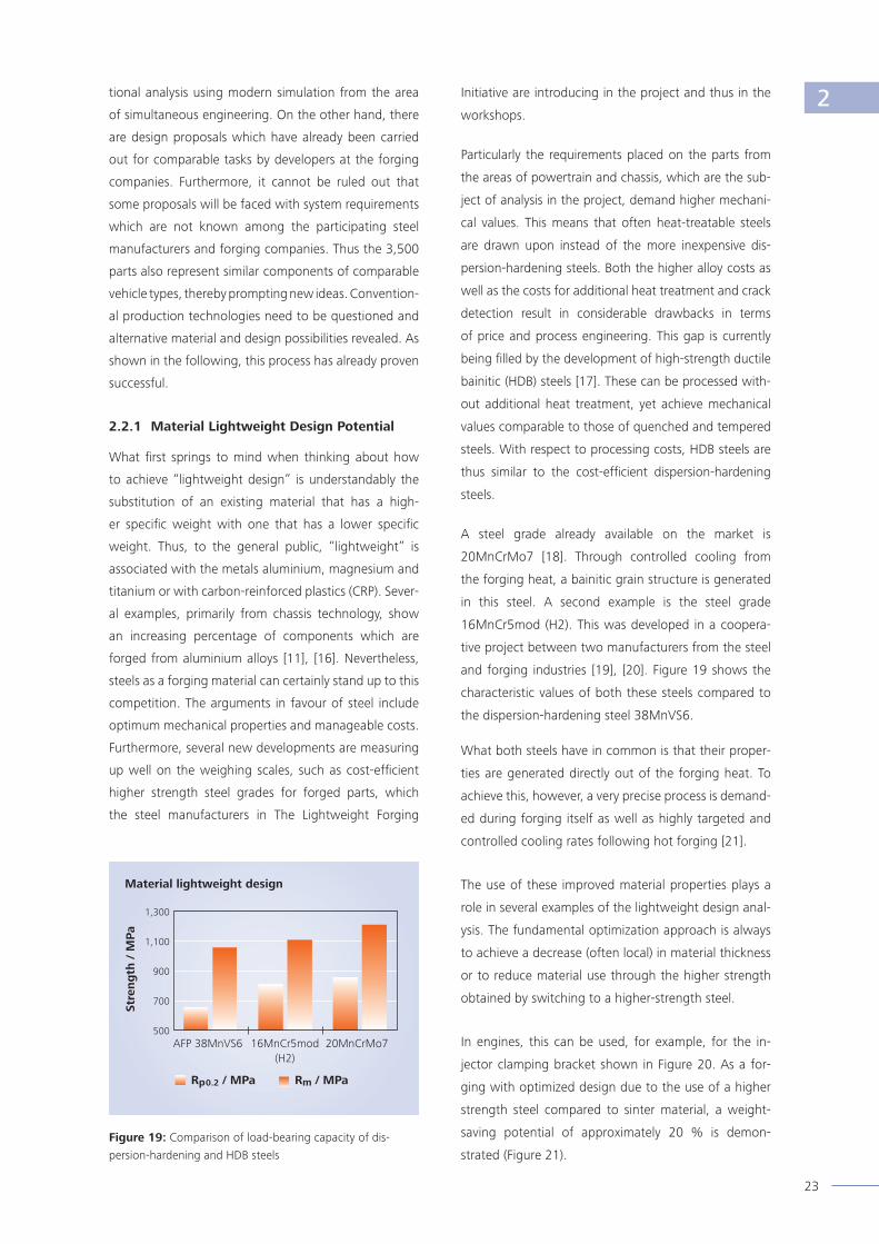
and forging industries [19], [20]. Figure 19 shows the
characteristic values of both these steels compared to
the dispersion-hardening steel 38MnVS6.
What both steels have in common is that their proper-
ties are generated directly out of the forging heat. To
achieve this, however, a very precise process is demand-
ed during forging itself as well as highly targeted and
controlled cooling rates following hot forging [21].
The use of these improved material properties plays a
role in several examples of the lightweight design anal-
ysis. The fundamental optimization approach is always
to achieve a decrease (often local) in material thickness
or to reduce material use through the higher strength
obtained by switching to a higher-strength steel.
In engines, this can be used, for example, for the in-
jector clamping bracket shown in Figure 20. As a for-
ging with optimized design due to the use of a higher
strength steel compared to sinter material, a weight-
saving potential of approximately 20 % is demon-
strated (Figure 21).Figure19: Comparison of load-bearing capacity of dis-
persion-hardening and HDB steels
Materiallightweightdesign
1,300
1,100
900
700
500
Stre
ng
th/
MPa
AFP 38MnVS6 16MnCr5mod (H2)
20MnCrMo7
Rp0.2/MPa Rm/MPa
2

24
Figure22: left – input shaft front, right – coupling rod front
Two parts from the powertrain and chassis may also be
produced using this lightweight design idea. From the
powertrain, the front drive shafts produced in this way
likewise reveal a potential weight saving of 20 % (Figu-
re 22, left). From the chassis, the coupling rods dem-
onstrate an estimated weight-saving potential of 5 %
(Figure 22, right). In the case of these coupling rods,
one proposal is to substitute the dispersion-hardening
steel used to date with HDB steel.
Another example of lighter dimensioning as a result of
switching to a higher strength and tougher steel is the
tow coupling, which is a representative of add-on com-
ponents. For the tow coupling shown in Figure 23, a
possible weight reduction of 10 % is determined.
One area of weight-saving potential which has not
yet been presented here is achieved through the use
of fastening elements of a higher strength class and
correspondingly smaller dimensioning. From the study,
an idea emerged which involves reducing the dimen-
sioning of screws for fastening the connecting rod cap
and shaft from M8 to M7 as well as fi nding other ways
of decreasing the weight of the forged connecting
rod (Chapter 2.2.2). This also leads to secondary light-
weight design potential with respect to the crankshaft
and the mass balancing system.
Particularly by taking into account the large number of
fastening elements in a vehicle, the low savings which
Figure20: Clamping bracket for injectors Figure21: Clamping bracket for injectors – savings potential
when using a higher strength material and subsequent
design modifi cations
Seriesgeometrysintered
Figure23: Ball head of the tow coupling
2 Series Potential

25
the individual elements bring can soon add up to a re-
markable savings potential. This leads to the idea that the
principal design criterion may not be the components
that need to be fastened but rather the strength of the
fastening elements themselves.
2.2.2 LightweightPotentialthrough
StructuralDesignandManufacture
Through consistent application and pursuit of proven FE
methods at an early phase of development, additional
lightweight design potential may be tapped through
structural design and production considerations, as the
following examples from the analysis of lightweight de-
sign potential show.
The forged crankshaft, as a complex engine compo-
nent, is shown in Figure 24.
Through optimizations to the geometry of the crank-
shaft, which has a mass of 13.9 kg, the material in the
marked area of the pin bearings may be reduced by
forging recesses into it (Figure 25, left and centre). A
rough calculation of imbalance reveals additional ma-
terial savings on the counterweights, too (Figure 25,
right).
The lightweight design potential that may be achieved
using higher strength fastening elements for the con-
necting rod caps, as outlined in the previous chapter,
can also be used for changing the geometry of the con-
necting rod. Retaining the required wall thicknesses,
the connecting rod (Figure 26) can now be designed
narrower and thinner. Furthermore, such weight re-
ductions in moving masses result in greater secondary
effects in the engine, which in turn prompt additional
improvement potential in bearings or balancer shafts.
By taking these secondary effects into account, the
weight-saving potential in the engine amounts to ap-
proximately 1 kg.
Additional lightweight design potential may be tapped
by fully exploiting the shaping possibilities offered by
forging. Figure 27 shows the common rail that was
analysed from the reference vehicle; Figure 28 com-
pares the common rail from Figure 27 with a proposal
for reducing component cross-sections.
In this case, it is essential to take into account the in-
sights described in [22] relating to the use of materials
which permit considerable upsetting of the steel with-
out causing a drop in their load-bearing capacity. In ad-
dition, the use of a low-sulphur dispersion-hardening
steel needs to support the material savings. As shown
Figure25: Crankshaft – Comparison of the series part and the lightweight design proposal
Figure24: Crankshaft of the reference vehicle
Newcontour
Old contour
2
Series Potential

26
in the comparison between the series part and the
lightweight design proposal, the equivalent stress is
almost identical.
The optimization potential just described relates to
elements of the engine in the reference vehicle; in the
following, the ideas concern components in the trans-
mission or transfer gearbox.
In the fi rst example, one key insight is that in the case
of crowned teeth which bear the load in the centre, the
main bending load of the teeth lies in the centre of the
tooth. It should thus be possible to minimize material
at the tooth ends. The gear wheel component for the
5th gear on the input shaft shown here has a mass of
0.41 kg in its series form (Figure 29). Subject to additional
strength calculations which still need to be carried out,
this mass may be reduced by 20 %. In Figure 30, the
weight-optimized design is shown in a tilted top view
and in cross section.
As a second example, Figure 31 shows the shaft in the
transfer gearbox with a weight of 1.38 kg. The light-
weight design potential is identifi ed below the hypoid
gears, i. e. in the transition area to the shaft, and
amounts to around 20 % (Figure 32). Correspondingly,
it is thus possible to forge an annular recess which no
longer needs to be machined, depending on imbalance
requirements. Furthermore, a hole can be introduced
into the shaft centre. This hole cannot be produced
cost-effectively using forging. While this generates a
small additional effort in soft machining, the process
should nevertheless prove cost-effi cient when calcula-
ting “Costs per kg forged part” [23].
Figure26: Connecting rod – Geometrical savings potential
through use of higher strength screws and reduction of
screw diameter
Figure28: Common rail: Comparison of geometries
Figure30: Gearwheel 5th gear: Comparison of the original
and modifi ed profi le
Figure27: Common rail
Figure29: Gearwheel 5th gear of input shaft
vonMisesstress
V/MPa
500
400
300
200
100
0
2
Series
Series
Potential
Potential

27
Further along the powertrain, behind the transfer gear-
box, are the companion fl anges for connecting the
input shafts. The starting mass here amounts to 1.2 kg
for the left and 1.9 kg for the right fl ange (Figure 33).
The following example is a lightweight design proposal
for the companion fl anges of the rear drive. The weight-
saving potential draws upon several proposals. The most
notable is the deviation from a rotationally symmetric
geometry, as the contour between the bolt holes may
be provided with considerable recesses. Furthermore,
the cylindrical form of the shaft is interrupted by radial
pockets forged into the part. Intensive material savings
are achieved not least through the conical inner geome-
try which is designed much deeper than the series part.
However, these initial analyses also reveal that torsion-
al stiffness decreases by approximately 14 % with this
solution. The measures presented add up to a weight-
saving potential of around 0.21 kg, which makes a
saving of 21 % in the case of the left fl ange (Figure 34).
For the input shaft shown in Figure 35, with a mass of
1.34 kg, a weight-saving potential of around 5 % was
demonstrated. This was achieved through a weight-
optimized design for forging in the form of material
removal at the transition area from the hollow shaft to
the fl ange, as shown in Figure 36.
In the chassis, a large number of lightweight design
ideas were found for the four wheel bearings assem-
bled in the reference vehicle (Figure 37). While this
highlights the great signifi cance of these components,
it also points to the fact that, as rotationally symmetric
parts, their design to date has been dominated by eco-
nomic considerations rather than with respect to light-
weight design aspects.
They contribute a total of 6.96 kg to the vehicle weight,
and thus call for lightweight design potential to be tap-
ped here.
Figure32: Shaft of the transfer gearbox – Comparison of
the series part and the lightweight design proposal
Figure31: Shaft of the transfer gearbox – real part
Figure33: Companion fl ange input shaft – rear right Figure34: Companion fl ange of the input shaft (rear) –
Comparison of the series part and the lightweight design
proposal
2,250
1,800
1,350
900
450
0
V/MPa
2
Series
Potential
Series Potential

28
The solution presented in the following is highly am-
bitious and presents process engineers with a chal-
lenge. Initially, the rotationally symmetric fl ange is given
a pentagonal external geometry by means of recesses.
Furthermore, fi ve individual contact surfaces of the re-
quired thickness are provided for mounting the wheel.
Between these contact surfaces, the material is pro-
duced considerably thinner than is the case with the series
part. In addition, the wheel hub journal has recesses,
and on the side facing away from bearing journal, a
stiffness optimized internal contour is proposed. Be-
sides this, the centring ring used to date for centring
the wheel rim hole contains several recesses, rendering
the part highly challenging to produce by means of
forging (Figure 38). The total weight-saving potential
for four parts has been calculated as 2.88 kg.
Similar considerations have led to the following light-
weight design proposal for the companion fl anges of
the propeller shaft (Figure 39), each of which weighs
0.56 kg in the reference vehicle. By reducing material
in the area of the bolt holes and on the opposite side
to the wheel hub, as shown in Figure 40, the weight-
saving potential lies at approx. 20 %.
It seems evident from the previous examples that in
lightweight design analyses, the supposedly complex
components of the powertrain and chassis hold the
greater share of weight-saving potential.
By taking another look at the numerous and indispens-
able fastening elements, another radical idea emerges.
The geometry of a hexagon nut with fl ange undergoes
fundamental change through material savings on the
hexagon surfaces using the design possibilities offered
by cold forging (Figure 41).
This measure requires verifi cations of strength in
simulation and testing. Figure 42 shows example
Figure35: Input shaft – real part Figure36: Input shaft – Comparison of the series part and the
lightweight design proposal, and real part
Figure37: Wheel bearing left Figure38: Wheel bearing – Comparison of the series part
and the lightweight design proposal
2
Series Potential
Series Potential

29
results of an FEA analysis of a hexagon nut and a light-
weight design nut with fl ange using loads according to
DIN EN ISO 898-2 [24].
By comparing the results of the structural-mechanical
simulations for the reference geometry with the results
for the lightweight design geometry, similar values are
obtained for equivalent stress (von Mises) and plastic
strain. In principle, it is thus possible, within the given
structural-mechanical boundary conditions, to achieve
minimization of mass through reducing partial volumes
that do not contribute directly to load-carrying capacity
and mechanical function [25].
This patented lightweight design nut is stated as achiev-
ing a mass reduction of up to 20 % compared to con-
ventional standard nuts using conventional fastening
technology and omitting heat treatment (tempering
and quenching) for achieving the strength class “10”
according to DIN EN ISO 898-2 [26].
Although in absolute terms, only a few grams are saved
per part, the high number of such fastening elements
renders this weight-saving potential highly interesting.
Figure40: Companion fl ange of the drive shaft – Com-
parison of the series part and the lightweight design proposal
Figure39: Companion fl ange of the drive shaft
Figure42: Equivalent stress state V (von Mises) using loads according to DIN EN ISO 898-2 left: Hexagon nut, right: Lightweight
design nut, each with fl ange, M 14 x 1.5
1,100
900
800
700
550
450
300
200
150
0
V/MPa
2
Figure41: Hexagon nut with fl ange and following weight
optimisation
Series Potential
Series Potential

30
2.2.3 ConceptualLightweightDesignPotential
Lightweight design generated by means of new con-
cepts generates greater implementation hurdles, as it
is of a disruptive nature and thus initially subordinate
to established products. However, by exploiting the ad-
vantage of lower weight, they are certainly in a position
to be well received in future.
One example of such a lightweight design proposal is
shown in Figure 43. Here, the implementation possi-
bility still needs to be tested out. The proposal fore-
sees that instead of a fl ange connection using screws,
torque transfer is achieved via a Hirth face gear, which
is highly capable of bearing loads and which may be
produced ready-for-assembly both on the output shaft
as well as on the tripods. This would involve substitut-
ing the six individual screws used to date with a single
unit nut. The proposal thus not only leads to a reduc-
tion in weight of 828 g or 25 % but also to the omission
of the welding process and to a reduction of effort in
vehicle assembly.
2.3 Summary and Conclusion
In the largest pre-competitive joint project known as
“The Lightweight Forging Initiative”, 15 forging com-
panies and 9 steel manufacturers have carried out a
study on lightweight design potential. The goal was to
demonstrate and provide a detailed description of the
lightweight design potential of forged components as
well as to implement concrete lightweight design pro-
posals for a passenger car.
Contents of this study included
• a context analysis for obtaining an overview of pre-
vious studies and publications on the topic of light-
weight design,
• benchmarking the components of a reference vehi-
cle, which was systematically disassembled, recorded
and documented for this purpose,
• identifying and documenting lightweight design
ideas using three different hands-on workshops and
• deriving lightweight design potential as well as imple-
menting substantiated lightweight design proposals.
This project has generated 399 formulated proposals
with an overall weight-saving potential of more than
42 kg. These weight savings are derived from the fol-
lowing analysed assemblies:
• powertrain,
• chassis and
• other components
Figure43: Conceptual lightweight design in the powertrain
2
Series Potential

31
The proposals were categorized as ideas relating to:
• material lightweight design,
• lightweight potential through structural design and
manufacture as well as
• conceptual lightweight design.
In addition, the cost impact and implementation effort
of each proposal were estimated, ultimately leading to
classification of the overall implementation potential.
The multi-dimensional approach leads to useful results
and is of great value for additional bilateral projects be-
tween material and component suppliers together with
automotive customers.
2

32
Transfer of Insights to Development Processes and Research Projects
3.1 Transfer of Insights to
Development Processes
It goes without saying that a wealth of development
know-how existed among the participating forging and
steel manufacturing companies prior to the study on
lightweight design potential and that, corresponding-
ly, a majority of the insights gained from the project
are not completely new. Quite the contrary: Published
developments or even patented processes were also
drawn upon in the study. Through the additional ideas
and input which were the result of cross-sector and
interdisciplinary cooperation, the participating experts
achieved an overall weight-saving potential of 42 kg in
the reference vehicle by exploiting specialist know-how
with respect to materials and heat treatment.
The primary result of the joint project is the ability to
work with these interdisciplinary ideas, and to transfer
them to new challenges faced by the relevant supplier
with each new customer inquiry that they receive. The
project was particularly beneficial to those companies
which have worked less intensively to date on opti-
mizing the material of their products.
Through vehicle disassembly and the impressions of the
highly haptic hands-on workshops, all participants have
gained a much deeper insight into the state of the art.
It also highlighted the applications in which automotive
customers are already using forgings as well as poten-
tial applications which had not been identified
previously.
Finally, the joint project continues the rethinking pro-
cess that began a long time ago. Cooperation – includ-
ing with research institutes and associations – is being
received much more positively. Development times can
be reduced by early cooperation, while inefficient and
thus costly development loops should be avoided with
steel manufacturers and forging companies.
3.2 Research Approaches
In outlining the insights gained from the study on light-
weight design potential described in Chapter 2, the
need for additional research was pointed to. The Light-
weight Forging Initiative is proposing a lead technology
project for SME to AiF (an alliance of research associ-
ations) / BMWi (Federal Ministry for Economic Affairs
and Energy).
The goal is to fully exploit the lightweight design poten-
tial of forged components in automotive engineering
by developing new processes in forging and develop-
ment as well as by using more efficient steels and heat
treatment operations.
Here, the leading research institutes from the process
chain of steel manufacture – forging – heat treatment –
machining have been integrated and have worked on
research clusters based on the results of the study on
lightweight design potential. These research clusters
will be developed over the coming three years together
with 50 companies from the industry.
The activities named here thus emphasize the impor-
tance of the cooperation between steel manufacturers
and developers from forging companies as a solid basis
for a professional development partnership in the auto-
motive industry. This task of this cooperation is not only
to find answers to the challenge of emission reductions
but also to implement production-ready solutions at an
early stage.
3

33
Additional Lightweight Design Potential with Forging
Beyond the examples presented above, the perfor-
mance of the industry is also demonstrated through
optimization measures developed outside of the work-
shops on lightweight design potential. In the following,
individual lightweight design solutions will be present-
ed which were not developed specifi cally for the ref-
erence vehicle, but were already being used in other
applications.
Gearwheels are attracting particular attention due to
the high total number of them in transmissions. The
arm and wavy profi les shown in Figure 44 form the
starting point for an innovative lightweight design con-
cept. Through new and patented design, the material
below the tooth ends may be reduced by a third. At
the same time, the gearwheel can be optimized with
respect to distortion behaviour using heat treatment
processes. Due to the optimized fi bre fl ow of this
gearwheel, the advantages of a forged vehicle
component can be exploited to the full, as the part can
be adapted to the load case, ultimately leading to the
goal of a higher fatigue limit [28]. This results in light
yet high-strength speed and differential gears.
Accordingly, Figure 45 shows a CAD study on the further
development of transmission parts with the aim of
reducing the rotatory masses and increasing the pow-
er density of the parts. Reduced wall thicknesses and
the move away from a rotationally symmetric design
are pursued consistently here.
The same is true of the precision-forged speed gear
shown in Figure 46. Starting with a classic rotationally
symmetric cross section, the part was provided with a
suffi cient number of stiffening radial arms between the
Figure44: Wavy gearwheels
Figure45: Gearwheel study for reducing rotatory masses Figure46: Near-net-shape design of a precision-forged
speed gear
4

34
wheel hub and the gear rim. Furthermore, material was
removed between these arms by means of punching to
achieve maximum weight savings.
Finally, the continuous further development of differential
pinions (Figure 47) should be mentioned as an example of
potential lightweight design. Optimizing the tooth geo-
metry leads to an increase in load-bearing capacity and
thus, under constant load requirements, to a downsizing
of the differential through a more compact design.
One proposal generated from the idea of substituting a
cast part with a forged one combined with a greatly mod-
ifi ed geometry is shown in Figure 48. For a crankshaft
bearing of a ship engine, a weight-saving potential of
0.28 kg may be achieved using a load-optimized forged
part.
Through a process combination of traditional cold for-
ging and radial forging, the hollow shaft of an auto-
matic transmission shown in Figure 49 is generated.
This is also a part not found in the reference vehicle.
Besides optimized material use and the resulting light-
weight design, the cold forged lubrication grooves
are also noteworthy, as they provide the hollow shaft
with a functionally optimized internal contour [16].
Similar to the situation with fastening elements, the
savings potential of smaller parts must always be seen
as part of the overall weight-saving potential. In the
case of the chassis bearings shown in Figure 50 and
Figure 51, the weight difference multiplies with the
number of bearings in a vehicle. Figure 50 shows a
rear-axle bearing assembled four times in the vehicle.
This bearing is not only hollow in design but is also
provided with an internal undercut. The internal contour
Figure49: Hollow shaft of a modern automatic transmission
with weight-optimized design
Figure48: Crankshaft bearing as a forged part with design
optimization
Figure47: Optimized differential bevel gear set
Figure50: Chassis bearing for rear axle made of aluminium
4

35
Figure51: Chassis bearing for front axle wishbone made of
steel
4may be generated cost-effi ciently by means of cold for-
ging. In addition, material lightweight design was used
for this bearing, with steel being replaced by aluminium
and with the generation of a larger contact surface.
An example of a material lightweight design approach
already outlined is represented by the chassis bearing
for a wishbone of the front axle (assembled twice in
the vehicle). Here, a higher strength steel was used as
a substitute material. At the same time, the undercut
between the contact surfaces shown in Figure 51 was
employed as a design optimization principle of cold
forging.

36
Summary and Outlook
As a result of informal talks at the SCT steel conference
for automotive applications in 2011, a consortium of
9 steel manufacturers (Steel Institute VDEh) and 15
forging companies founded The Lightweight Forging
Initiative. In a first multilateral project, a study on light-
weight design potential was carried out from February
to October 2013. In this study, the lightweight design
potential of a reference vehicle (significant series vol-
ume, estate car, diesel, double-clutch transmission, all-
wheel drive) was developed within the context of three
workshops following disassembly of the car into its in-
dividual components. The result was a weight-saving
potential of 42 kg or over 5 % based on the vehicle
areas analysed and relevant to forging. The study was
conducted and documented by fka Forschungsgesell-
schaft Kraftfahrwesen mbH Aachen, an automotive en-
gineering research institute.
The outcome is seen as positive by both the steel man-
ufacturers and the forging companies. The steel man-
ufacturers welcome the improved communication be-
tween the forging companies and the steelworks [7].
Furthermore, the dialogue has confirmed that a high
number of similar but not quite the same materials
are used, which considerably increases inventories and
production effort as well as costs thereof. What also
emerged was that materials were not being used to their
full potential, both as material themselves as well as with
respect to properties. Similarly, the experts uncovered
materials whose technical possibilities – taking into ac-
count relevant safety values – were not being exploited
fully or even at all [21]. The participants agree that the
readiness of the OEMs to use new steels in their vehicle
components needs to evolve. What can still be seen is
a greater willingness to accept the effort involved in
adapting a part by switching to newer, supposedly
lighter non-ferrous materials than the readiness to
achieve weight savings by using high-strength steel
with appropriate changes in geometry.
The joint cooperation of The Lightweight Forging Ini-
tiative has shown that these hurdles should be easier
for automotive manufacturers to tackle than was pre-
viously thought. Furthermore, it should be possible to
present the ideas and concepts to the manufacturers in
a form which would not have been possible for indivi-
dual members of the Initiative [28].
From the viewpoint of the forging companies, the top-
ic is not new in itself (Chapter 1). Instead, the moti-
vating factor for participating in the Initiative was the
cross-sector bundling of know-how across the entire
process chain. Through this, the industry practitioners
recognize to an even greater extent the conflicting
areas of weight reduction, cost potential and, above
all, implementation effort. For the forging companies,
it is therefore essential to include material and forging
potential in the early phases of system and part devel-
opment. Here, there are tried-and-tested simultaneous
engineering processes. However, these need to be used
for considerably more components than at present. The
purchasing process of the automotive manufacturer
should take place in earlier phases of development,
namely when lightweight design proposals of the
supplier can still flow from material or production
engineering into part design.
It should also not be forgotten that in the case of the
lightweight design ideas for the powertrain with a
weight reduction volume of 25.5 kg, 7.9 kg may be
achieved only with additional costs of 10 to 20 % This
may be compensated for in part by means of other
lightweight design components which can be pro-
duced more cost-efficiently than in the past. However,
the fact remains that, overall, a lighter car design will
lead to slightly higher procurement costs. What is
positive is the willingness of car buyers to pay more for
ecological solutions, as verified in several studies. This
is particularly the case if these costs are later compen-
sated for through lower energy consumption. This, too,
will promote the trend toward lightweight design [27].
Another common insight of the benchmark is that by
using the latest steel materials and forging technolo-
gy, the costs per kilogram lightweight design even lies
below that incurred for some more recent types of
technology. And what is more, some lightweight de-
sign potential even promises cost neutrality. Overall, the
results verify both quantitatively and, above all, qualita-
5

37
tively the sheer power of innovation demonstrated by
steel manufacturers and forging companies [29].
Future activities of The Lightweight Forging Initiative
will include continuous communication of the results
at symposia and conferences of the automotive industry.
This will also encompass regular lecture events to
present the results of the participating companies in
greater detail and to discuss lightweight design poten-
tial directly with a large number of experts.
Figure52: Lightweight design potential of forged components in cars
5

38

39
List of References
[1] Ernst, C.-S.; Göbbels, R.; Olschewski, I.: Leichtbaupotenziale massivumgeformter Komponenten im Pkw,
Final presentation of The Lightweight Forging Initiative, 24 October 2013, Düsseldorf.
[2] Ernst, C.-S.; Eckstein, L.; Olschewski, I.: CO2-Reduzierungspotenziale bei Pkw bis 2020, Final report,
December 2012, ika, RWTH Aachen.
[3] Brücher, T.; Raedt, H.-W.: Megatrends im Automobilbau – Beitrag Massivumgeformter Komponenten, Neuere
Entwicklungen in der Massivumformung, 3 - 5 June 2013, Fellbach, ISBN 978-3-88355-395-5.
[4] Friedrich, H. E. (publisher): Leichtbau in der Fahrzeugtechnik, ATZ / MTZ reference book, Springer Vieweg,
2013, ISBN 978-3-8348-1467-8.
[5] Bartsch, K.: Stahlhart und doch federleicht?, SEISSENSCHMIDT-NEWS 03/2013, Customer magazine of the
SEISSENSCHMIDT Group, Plettenberg.
[6] www.massiverLEICHTBAU.de
[7] Dahme, M.: “Massiver Leichtbau” – Eine Strategie für Leichtbaulösungen durch Massivumformung, Schmiede-
JOURNAL, September 2013, pp. 14 - 17, Industrieverband Massivumformung e. V (publisher), ISSN 0933-8330.
[8] Raedt, H.-W.: Leichtbau durch Massivumformung, Information series for forging, Special issue, 2010,
Industrieverband Massivumformung e. V. (publisher), ISBN 3-928726-20-X.
[9] Kucharzewski, A.: Massivumformung – eine Prozesskette für den Leichtbau, lightweightdesign 2/2010,
pp. 34 - 40, Springer Fachmedien, Wiesbaden, ISSN 1865-4819.
[10] Weidel, S.: Intelligenter Leichtbau durch Massivumformung, lightweightdesign 1/2013, pp. 34 - 38, Springer
Fachmedien, Wiesbaden, ISSN 1865-4819.
[11] Vollrath, K.; Severin, F.: Leicht, hochfest und äußerst zuverlässig, Vorteile von Aluminium-Schmiedeteilen,
SchmiedeJOURNAL, Issue March 2014, pp. 20 - 25, Industrieverband Massivumformung e. V. (publisher),
ISSN 0933-8330.
[12] Zitz, U.; Kucharzewski, A.: Die Kunst der Vielseitigkeit, UMFORMtechnik 3/2012, pp. 25 - 28, Meisenbach,
Bamberg, ISSN 0300-3167.
[13] Quintenz, G.; Raedt, H.-W.: FEM-optimierte Leichtbau-Hohlwellen für das Getriebe, Automotive magazine
ATZ 12/2009, Springer Fachmedien, Wiesbaden, ISSN 0001-2785.
[14 Grupp, P.: Leichtbau inside, Automobil Industrie insight, Special issue September 2012, pp. 62 - 64, Vogel
Business Media, Würzburg, ISSN 0005-1306.
[15] Vollrath, K. et. al.: Simulation in der Massivumformung, Information series for forging, Special issue, 2013,
Industrieverband Massivumformung e. V. (publisher), ISBN 978-3-928726-30-6.
6

40
[16] Witt, S.: Innovationsmotor Massivumformung, Special publication of the German Forging Association (Indus-
trieverband Massivumformung e. V.) with automotive magazine ATZ, Springer Fachmedien, Wiesbaden, 2010.
[17] Raedt, H.-W.; Speckenheuer, U.; Vollrath, K.: Neue massivumgeformte Stähle, Energieeffiziente Lösungen
für leistungsfähigere Bauteile, Automotive magazine ATZ 03/2012, Springer Fachmedien, Wiesbaden,
ISSN 0001-2785.
[18] Engineer, S.; Justinger, H.; Janßen, P.; Härtel, M.; Hampel, C.; Randelhoff, F.: Technological Properties of the
New High Strength Bainitic Steel 20MnCrMo7, 3rd International SCT (Conference Steels for Cars and Trucks),
5 - 9 June, 2011, Salzburg, Austria, 2011.
[19] Raedt, H.-W.; Speckenheuer, U.; Vollrath, K.: Neue Stähle für die Massivumformung, Information series for
forging, Special issue, 2012, Industrieverband Massivumformung e. V. (publisher), ISBN 978-3-928726-28-3.
[20] Project IFG 260 ZN: Effektive Prozessketten und neue hochfeste (bainitische) Stähle zur flexiblen Darstellung
hoch beanspruchter Strukturbauteile (HDB-Schmiedestahl, Bainite), Industrieverband Massivumformung e. V.,
2007.
[21] Wilke, F.: Stabstahl und Schmiedestücke aus hochfesten Stählen, SchmiedeJOURNAL, Issue March 2014,
Industrieverband Massivumformung e. V. (publisher), ISSN 0933-8330.
[22] Raedt, H.-W., Herz, M., Schuster, A.: Ausfälle durch verformte Mangansulfide, Konstruktion January / February
1- 2/2012, ISSN 0720-5953.
[23] Raedt, H.-W.; Wilke, F.; Ernst, C.-S.: Initiative Massiver Leichtbau – Leichbaupotentiale im Automobil
durch Massivumformung, Automobiltechnische Zeitschrift ATZ 3/2014, pp. 58 - 64, Springer Fachmedien,
Wiesbaden, ISSN 0001-2785.
[24] DIN EN ISO 898-2: Mechanische Eigenschaften von Verbindungselementen aus Kohlenstoffstahl und
legiertem Stahl, Teil 2 (Part 2): Muttern mit festgelegten Festigkeitsklassen – Regelgewinde und Feingewinde,
German version, August 2012.
[25] Unseld, P., Kertesz, L., Meßmer, G.: Geometrischer und stofflicher Leichtbau durch im Kaltumformverfahren
hergestellte mechanische Verbindungselemente, Conference on “Recent Developments in Forging”,
4 - 5 June 2013, pp. 253 - 270, ISBN 978-3-88355-395-5.
[26] Unseld, P., Kertesz, L., Meßmer, G.: Leichtbau durch Kaltverformung mechanischer Verbindungselemente,
SchmiedeJOURNAL, Issue March 2014, Industrieverband Massivumformung e. V. (publisher), ISSN 0933-8330.
[27] Bartsch, K.: Megatrend Leichtbau – Unternehmen der Massivumformung sind Partner mit dem notwendi-
gen Know-how, SchmiedeJOURNAL, Issue March 2014, Industrieverband Massivumformung e. V. (publisher),
ISSN 0933-8330.
[28] Günther, Chr., Saarstahl AG: Personal communication, December 2013.
[29] Kippels, D.: Umformtechnik speckt Automobile ab, VDI-Nachrichten No. 1/2014, VDI-Verlag, Düsseldorf.
6

41
7List of Figures
Figure 1 ika Institut für Kraftfahrzeuge RWTH Aachen University
Figure 2, 3, 9, 11, 12, 13, 15, fka Forschungsgesellschaft Kraftfahrwesen mbH Aachen
16, 17, 20, 22, 23, 24,
27, 29, 31, 33, 35, 37, 39
Figure 4, 14, 18, 19 The Lightweight Forging Initiative
Figure 5, 7, 21, 28, 34, 38, Hirschvogel Automotive Group
40, 43
Figure 6 Bharat Forge Aluminiumtechnik GmbH & Co. KG
Figure 8 Felss Systems GmbH
Figure 10 Industrieverband Massivumformung e. V.
Figure 25 CDP BHARAT FORGE GmbH
Figure 26 KAMAX Automotive GmbH
Figure 30, 32, 36, 44 SEISSENSCHMIDT AG
Figure 41, 42 HEWI G. Winker GmbH & Co. KG
Figure 45 Sona BLW Präzisionsschmiede GmbH
Figure 46 metallumform GmbH
Figure 47, 49 Metaldyne Zell GmbH & Co. KG
Figure 48 Hammerwerk Fridingen GmbH
Figure 50, 51 A. + E. Keller GmbH + Co. KG
Figure 52 anidesk, Saarbrücken

42


Industrieverband
Massivumformung e. V.
Goldene Pforte 1
58093 Hagen, Germany
Tel.: + 49 2331 958830
Fax: + 49 2331 958730
E-mail:
Further information:
www.massivumformung.dewww.massiverLEICHTBAU.de
ISBN: 978-3-928726-34-4
The publications of the
German Forging Association
(Industrieverband Massivumformung
e. V.) are based on the results of the
joint research of the consortium
of companies in the German
Forging Association.
Status: April 2014
EI-LB-0414-05