Embed Size (px)
Citation preview
International Research Journal of Engineering and Technology (IRJET) e-ISSN: 2395 -0056
Volume: 03 Issue: 04 | Apr-2016 www.irjet.net p-ISSN: 2395-0072
© 2016, IRJET ISO 9001:2008 Certified Journal Page 1649
Extraction of Pyrolysis oil from Waste Plastics
1Kanika Mathur, Assistant Professor, Dept. of Mechanical Engineering, Father C Rodrigues Institute of Technology, Maharashtra, India
2Chaudhari Shubham, Hegde Sunadh, Pawar Aditya, Kakad Hardeep Singh, UG student, Dept. of Mechanical Engineering, Father C Rodrigues Institute of Technology,, Maharashtra, India
---------------------------------------------------------------------***---------------------------------------------------------------------Abstract - There has been an ever increasing global demand for energy in recent years. The demand especially from liquid fuels is very high and the limited resources of fuel production has created bottleneck leading to an energy crisis. This has led to exploring other resources for fuel production, one of which is plastic. Being a non-degradable source, plastics disposed off in the open environment as wastes pose a threat to the environment. Most of the waste plastics end up as landfills. It can instead be used as a source for making fuel. The work describes an attempt to use the waste plastic to synthesize potential fuel called ‘Pyrolysis Oil’ since the process used in order to obtain the oil is Pyrolysis. The obtained oil from different grades of waste plastics is analysed so as to validate its use as fuel. The paper deals with extracting pyrolysis oil from waste polymers by fabricating an furnace to carry out pyrolysis.
Key Words: Waste Plastic, Pyrolysis, Pyrolysis Oil.
1. INTRODUCTION Management of plastic waste is a big issue in India. According to Central Pollution Control Board (CPCB), India generates 5.6 million tons of plastic waste annually and approximately only 60% of collected plastic waste is re- cycled. [1]Tons of Plastic waste is dumped on land and huge amounts are disposed of into the water bodies. These plastic wastes could instead be used for producing fuel. Pyrolysis of waste plastic could provide a better way to dispose off the waste plastic which causes environmental pollution.
Pyrolysis is a thermochemical decomposition of organic material at elevated temperatures in the absence of oxygen. Pyrolysis of organic substances produce gas and liquid products which are termed as bio-fuels and leave a solid residue richer in carbon content, char.
The project is thus selected with an objective of using this non degradable waste plastic as a source to extract fuel which after analysis can be used as an alternative source of energy.
Manish Chand Sharma [2] issued a paper in 2013 on “Production of alternative fuel from waste oil and comparison with fresh diesel”. This research paper compares the blend of fresh diesel and diesel obtained from pyrolysis of used engine oils with conventional diesel oil.
John William Bordynuik [3], issued a paper in March 2013 “Performance and Emission Evaluation of Blends of
Diesel fuel with Waste Plastic Oil in a Diesel Engine”, it studied Viable Production of Diesel from non- recyclable waste plastics.
C. Wongkhorsub et.al. [4] published a paper in July 2013 titled “A Comparison of the Use of Pyrolysis Oils in Diesel Engine”. This research describes a comparison of the use of pyrolysis oils which are the tire pyrolysis oil, plastic pyrolysis oil and diesel oil in the assessment of engine performance, and feasibility analysis. Pyrolysis oils and waste plastic are studied to apply with one cylinder multipurpose agriculture diesel engine. Thus, a comparison between the two is studied.
2. MODELLING AND FABRICATION OF SETUP The proposed assembly of the experimental setup was modelled in Solid Works software with certain specifications. The need of different components was determined by the layout and was modelled based on the holding capacity of the heating chamber. The parts have been marked according to the parts list.
Table -1: Parts list for the setup
Sr. No Part Name Quantity
1 Frame 1
2 Heating Chamber 1
3 Furnace (Heating coil of 3kW)
1
4 Insulations
1
5 Condenser
1
6 Tank
1
7 Bracket
1
8 Gasket
1
9 Nut, Bolt & Washer
8
International Research Journal of Engineering and Technology (IRJET) e-ISSN: 2395 -0056
Volume: 03 Issue: 04 | Apr-2016 www.irjet.net p-ISSN: 2395-0072
© 2016, IRJET ISO 9001:2008 Certified Journal Page 1650
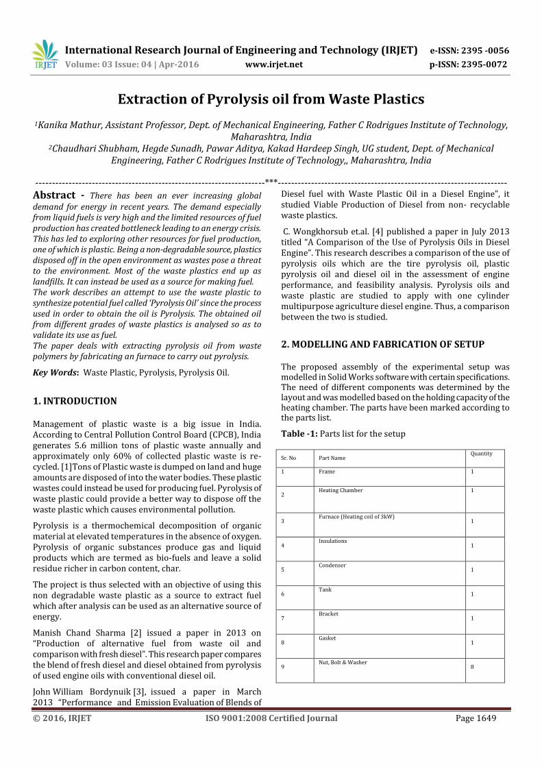
Fig -1: Proposed assembly of experimental setup
The basic components of the setup include a heating unit, a cooling unit and collection unit. The model of the proposed assembly helps to give a better idea and understanding of the setup and helps in the fabrication of components.
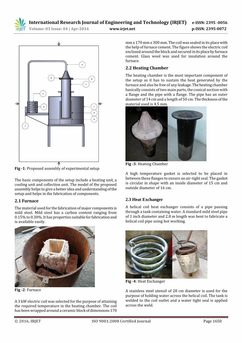
2.1 Furnace
The material used for the fabrication of major components is mild steel. Mild steel has a carbon content ranging from 0.15% to 0.30%. It has properties suitable for fabrication and is available easily.
Fig -2: Furnace
A 3 kW electric coil was selected for the purpose of attaining the required temperature in the heating chamber. The coil has been wrapped around a ceramic block of dimensions 170
mm x 170 mm x 300 mm. The coil was sealed in its place with the help of furnace cement. The figure shows the electric coil enclosed around the block and secured in its place by furnace cement. Glass wool was used for insulation around the furnace.
2.2 Heating Chamber
The heating chamber is the most important component of the setup as it has to sustain the heat generated by the furnace and also be free of any leakage. The heating chamber basically consists of two main parts, the conical section with a flange and the pipe with a flange. The pipe has an outer diameter of 14 cm and a length of 50 cm. The thickness of the material used is 4.5 mm.
Fig -3: Heating Chamber A high temperature gasket is selected to be placed in between these flanges to ensure an air-tight seal. The gasket is circular in shape with an inside diameter of 15 cm and outside diameter of 16 cm.
2.3 Heat Exchanger
A helical coil heat exchanger consists of a pipe passing through a tank containing water. A standard mild steel pipe of 1 inch diameter and 2.8 m length was bent to fabricate a helical coil pipe using hot working.
Fig -4: Heat Exchanger A stainless steel utensil of 28 cm diameter is used for the purpose of holding water across the helical coil. The tank is welded to the coil outlet and a water tight seal is applied across the weld.

International Research Journal of Engineering and Technology (IRJET) e-ISSN: 2395 -0056
Volume: 03 Issue: 04 | Apr-2016 www.irjet.net p-ISSN: 2395-0072
© 2016, IRJET ISO 9001:2008 Certified Journal Page 1651
2.4 Frame
Fig -5: Frame The circular frame of 52 cm diameter and 42 cm length is prepared by rolling a sheet of metal and welding its ends. The bottom is welded with circular shape metal sheet of 3 mm thickness. The frame houses the furnace and the chamber and also provides thermal insulation.
3. ASSEMBLY OF PYROLYSIS SETUP Assembly of the setup follows the fabrication and testing of the components required for the process. The stand is placed where the setup is to be installed so as to conduct the experiment. The experiment is performed outdoors for safety. The frame is carefully placed on the stand. The next step involves carefully installing the furnace and the insulation bricks. Then carefully place the furnace in the center. The wires of the electric furnace are sealed in insulating material. Bricks are placed in the rest of the space surrounding the furnace. This ensures minimum heat loss from the furnace in all directions except the top. The frame lid is then used to cover the furnace inside the frame. The lid prevents heat loss. The penultimate step is inserting the heating chamber through the lid into the furnace. The final step of the assembly is placing the helical coil heat exchanger assembly on the stand.
Fig -6: Final setup For performance of the experiment, the material selected is first added to the heating chamber. The next step is placing the heat sealing gasket between the flanges and fastening the flanges using nut bolting. The fasteners are tightened so that
the gasket properly seals the flanges. No air leakage is tolerated as this may result into combustion of the polymers being used. The empty water tank is filled with water before starting the test. The water is filled so that the major part of the coil is immersed under water. This helps to increase the effectiveness in heat exchange. After final inspection the electric supply to the furnace is switched on and the experiment begins. A stopwatch is used so as to keep a track of observations with respect to time. After switching on the apparatus, approximately 15 minutes later it is observed that furnace starts heating considerably. This can be said as the hot fumes are seen rising up from the little gaps in the frame and the heating chamber. Approximately 40 minutes after the start it is observed that milky fumes are obtained from the outlet. Also the heat sealing gasket is seen to emit some fumes as it heats up. However these observations last for a few minutes until the entire setup attains high temperature (400°C+). Using 1.5 kg of plastic in the experimentation 85 minutes after the start of the experiment it is observed that drops of oil start falling from the outlet. A funnel and a flask for oil collection are placed below the outlet.
4. RESULTS AND DISCUSSION The setup is fabricated for performing experiments with different grades of plastic. Experiment is conducted with waste plastic from injection moulding (Grade 5) and following results were obtained. Table -2: List of experimental results
Plastic Input (Kg) Output (Kg)
Waste plastic from injection molding (Grade 5)
1.5 1.65
5. CONCLUSIONS The Pyrolysis process was carried out Grade 5 type of plastic materials. 1.65lt. of oil is obtained by using 1.5 Kg of plastic. Quantity and quality of oil can be varied by using different quantity of plastics of various grades.
REFERENCES [1] http://www.cpcb.nic.in/plastic-waste/statistics/2014
[2] Manish Chand Sharma, Neelesh Soni, “Production of Alternative Diesel Fuel from Waste Oils and Comparison with Fresh Diesel”, The International Journal of Engineering and Science (IJES), Volume 3, Issue 4, pp 54-58, 2013, ISSN (e): 2319 – 1813.
[3] Jane Pratoomyod, Dr.Ing. Krongkaew Laohalidanond, “Performance and Emission Evaluation of Blends of Diesel fuel with Waste Plastic Oil in a Diesel Engine”, International Journal of Engineering Science and Innovative Technology (IJESIT) Volume 2, Issue 2, March 2013 .

International Research Journal of Engineering and Technology (IRJET) e-ISSN: 2395 -0056
Volume: 03 Issue: 04 | Apr-2016 www.irjet.net p-ISSN: 2395-0072
© 2016, IRJET ISO 9001:2008 Certified Journal Page 1652
[4] C. Wongkhorsub, N. Chindaprasert, “A Comparison of the Use of Pyrolysis Oils in Diesel Engine”, Energy and Power Engineering, July 2013 (http://www.scirp.org/journal/epe).