Embed Size (px)
Citation preview

Department of Applied Mechanics CHALMERS UNIVERSITY OF TECHNOLOGY Gothenburg, Sweden 2015
Externally Divided Exhaust Period in a Turbocompound Heavy Duty C.I. Engine Thermodynamic and mechanical modelling in GT-SUITE Master’s thesis in Automotive Engineering
NANDEEP MYSORE, RAHUL KILPADI

2
MASTER’S THESIS IN AUTOMOTIVE ENGINEERING
Externally Divided Exhaust Period in a Turbocompound
Heavy Duty C.I. Engine
Thermodynamic and mechanical modelling in GT-SUITE
NANDEEP MYSORE, RAHUL KILPADI
Department of Applied Mechanics
Division of Combustion
CHALMERS UNIVERSITY OF TECHNOLOGY
Göteborg, Sweden 2015

4
Externally Divided Exhaust Period in a Turbocompound Heavy Duty C.I. Engine
Thermodynamic and mechanical modelling in GT-SUITE
NANDEEP MYSORE, RAHUL KILPADI
© NANDEEP MYSORE, RAHUL KILPADI, 2015
Master’s Thesis 2015:55
ISSN 1652-8557
Department of Applied Mechanics
Division of Combustion
Chalmers University of Technology
SE-412 96 Göteborg
Sweden
Telephone: + 46 (0)31-772 1000
Chalmers Reproservice
Göteborg, Sweden 2015

Externally Divided Exhaust Period in a Turbocompound Heavy Duty C.I. Engine
Thermodynamic and mechanical modelling in GT-SUITE
Master’s thesis in Automotive Engineering
NANDEEP MYSORE, RAHUL KILPADI
Department of Applied Mechanics
Division of Combustion
Chalmers University of Technology
ABSTRACT
Turbocompounding has been a development on heavy diesel engines to improve the
utilisation of exhaust heat energy. This system, however, introduces additional
pumping losses and exhaust back pressure. Previous research has shown that the
introduction of a divided exhaust period (DEP) to the turbocompound engine using
staggered timing on exhaust valves feeding individual manifolds lowers the exhaust
back pressure, improving engine breathing and behaviour. Exhaust flow is divided
into two distinct flow paths beginning at the exhaust valves – through the
turbocharger (blowdown), and bypassing it (scavenging). However, research showed
that using one exhaust valve for each flow path can significantly lower the effective
flow areas for exhaust gases at higher engine speeds. This leads to highly choked flow
and consequently reduced engine output. A solution proposed was the division of the
flow paths external to the exhaust port, henceforth named external DEP (ExDEP). In
this solution, both exhaust valves open identical to those of the original engine, but
the gas flow is divided downstream with the use of independent valves. By the use of
ExDEP on a turbocompounded diesel engine the above research resulted in a brake
specific fuel consumption benefit of up to 4% over a regular turbocharged engine.
This thesis project, conducted at the Advanced Technology and Research division of
Volvo Group Trucks Technology in association with the Combustion department of
Chalmers University, aims to implement and evaluate the effects of ExDEP on an
existing GT-SUITE simulation model of a two-stage turbocompounded Volvo
HDE13 engine. Various flow components (valve types) and architectures are
modelled. The effect of timing and phasing of the ExDEP valves on engine
performance is investigated. Resizing of the existing turbine is investigated due to the
altered gas flow. Rough CAD models are prepared to determine the feasibility of
physically incorporating such systems on existing engines.
A further adaptation to the existing engine model is the incorporation of CAD data of
a novel engine concept currently being developed at Volvo GTT, in order to study the
feasibility of ExDEP with this engine.
With the implementation of ExDEP, a primary advantage foreseen is that the exhaust
flow into the turbines can be constantly controlled. This eliminates the need for
variable geometry turbochargers, bringing large reductions in system cost and
complexity. It can enable other innovative technologies such as Miller cycle
operation, air hybrid operation when an air tank is coupled to the exhaust manifold
Key words: Simulation, GT-Suite, GT-Power, ExDEP, exhaust, turbocharger,
turbocompound

II

Contents
ABSTRACT ............................................................................................................... I
Contents ................................................................................................................... III
Preface ....................................................................................................................... V
Notations ..................................................................................................................VI
1 Introduction ............................................................................................................ 1
1.1 Motivation ....................................................................................................... 1
1.2 Objective ......................................................................................................... 2
1.3 Limitations and assumptions ........................................................................... 2
2 Theory and modelling approach ............................................................................ 3
2.1 Base model ...................................................................................................... 3
2.2 ExDEP architectures ....................................................................................... 4
2.3 Valve concepts ................................................................................................ 6
2.3.1 Rotary valves ........................................................................................... 6
2.3.2 Fast-acting valves ................................................................................... 10
2.4 Flow path modelling ...................................................................................... 14
2.4.1 Exhaust port and valve body .................................................................. 14
2.4.2 Blowdown manifold ............................................................................... 15
2.4.3 Scavenging manifold ............................................................................. 17
2.5 Single entry turbocharger .............................................................................. 18
3 Simulation ............................................................................................................ 19
3.1 Operating points ............................................................................................ 19
3.2 Simulation method ........................................................................................ 19
3.3 Parameters ..................................................................................................... 20
3.4 Performance parameters ................................................................................ 20
4 Results .................................................................................................................. 21
4.1 Observations .................................................................................................. 21
4.1.1 Volume sensitivity of the model ............................................................ 21
4.1.2 Exhaust port length ................................................................................ 22
4.1.3 Routing of scavenging flow ................................................................... 23
4.1.4 ExDEP valve diameters ......................................................................... 24
4.2 Simulation results .......................................................................................... 25
4.2.1 Brake Specific Fuel Consumption (BSFC) ............................................ 25
4.2.2 Attachment Power .................................................................................. 26
4.2.3 Mean Effective Pressures ....................................................................... 27

IV
4.2.4 Cylinder pressures .................................................................................. 29
5 Conclusions .......................................................................................................... 31
6 Future work .......................................................................................................... 33
7 References ............................................................................................................ 35

Preface
In this work, an existing GT-SUITE model of a Volvo HDE13 six-cylinder engine
with two-stage turbocompounding was adapted to incorporate ExDEP valves on each
cylinder. The dimensions and timing of these valves and the sizing of the low pressure
turbine were varied to study their effects on the brake specific fuel consumption
(BSFC) of the engine at common operating points. The valves were also modelled in
CAD to represent realistic solutions. The work was carried out from January 2015 to
June 2015 at the Advanced Technology and Research (ATR) division of Volvo Group
Trucks Technology.
We would like to extend our sincere gratitude to our supervisor Arne Andersson,
Program Manager (Advanced Concepts) at Volvo GTT/ATR for his steady guidance
and support. We are also grateful to Professor Sven B. Andersson of the Division of
Combustion at the department of Applied Mechanics at Chalmers University of
Technology, for all the advice and ready humour!
Our work would have been exponentially more tedious, even impossible, if not for the
unfailing support of Per Salomonsson, Tommy Simonsson and everyone at Volvo
GTT/ATR.
We would like to thank Fredrik Rahm and Per Andersson of Volvo GTT for their
valuable advice, expertise and encouragement.
Finally, special heartfelt thanks to Bincheng Jiang of Volvo GTT/ATR for the
immense assistance at the beginning of this project, and our colleague and good friend
Anoop Suryanarayana.
Göteborg, June 2015
NANDEEP MYSORE, RAHUL KILPADI

VI
Notations
Upper case
Ae Effective flow area (m2)
Ar Actual orifice area (m2)
BMEP Brake mean effective pressure (bar)
BP Brake power (kW)
BSFC Brake specific fuel consumption (g/kWh)
Cd Discharge coefficient
CO2 Carbon dioxide
NOx Oxides of Nitrogen
P Pressure (N/m2)
PMEP Pumping mean effective pressure (bar)
Lower case
m mass flow rate (kg/h)
Greek
Δ Difference
ρ Density (kg/m3)
Abbreviations
AMEP Attachment mean effective pressure (bar)
BLD Blowdown
CAD Computer aided design
DEP Divided exhaust period
EVO Exhaust valve open
ExDEP Externally divided exhaust period
GT-ISE Gamma Technologies Integrated Simulation Environment
SCV Scavenging

CHALMERS, Applied Mechanics, Master’s Thesis 2015:55 1
1 Introduction
1.1 Motivation
As stated by the European Council for Automotive R&D, there is a societal challenge
to reduce the fuel consumption of heavy duty road vehicles by at least 20% with
conventional control systems [1]. Technology known as turbocompounding is already
in use to improve the utilisation of exhaust waste heat by introducing a turbine in the
exhaust flow path and coupling this turbine to the engine crankshaft, thus converting
exhaust thermal energy into mechanical work. A drawback of this technology is the
increased back pressure in the exhaust path due to the flow resistance offered by the
turbocompound. Prior research dealing with single-stage turbocompounding [2] has
demonstrated that the part of the exhaust stroke after the initial high energy blowdown
pulse can bypass the high pressure turbine, allowing expulsion of exhaust gases
against a lower back pressure, hence increasing pumping work. This process of
dividing the exhaust stroke into distinct paths is known as Divided Exhaust Period,
and could involve either a division at the exhaust valves themselves (known as DEP),
or external to the cylinder exhaust valves (known as Externally DEP or ExDEP). This
improves cylinder scavenging and can enable a reduction in Brake Specific Fuel
consumption
As the DEP method requires staggered opening of the cylinder exhaust valves, it
results in greatly reduced flow area and leads to increased flow choking at each valve
[3], adversely affecting combustion characteristics. In comparison, ExDEP
architecture introduces additional valves downstream of the cylinder exhaust valves,
thus retaining cylinder exhaust flow properties.
The possibility of retaining the benefits of turbocompounding and yielding up to 4%
benefit in fuel consumption [3] while possibly reducing exhaust back pressure is the
motivation to conduct this Master’s Thesis work on Externally Divided Exhaust
Period.

2 CHALMERS, Applied Mechanics, Master’s Thesis 2015:55
1.2 Objective
The objective of this thesis is to implement and observe the effects of ExDEP in a
heavy duty diesel engine simulation model. This will be conducted through the
investigation of prior studies of ExDEP and the requirements for valve technologies.
Thermodynamic and mechanical models of an ExDEP system will be developed for
use in an existing engine model in GT-SUITE to observe changes in fuel
consumption.
1.3 Limitations and assumptions
In order to ensure the delivery of a working and well-documented model within the
time frame of this project, some conditions and boundaries were necessitated:
- Transient operation of the engine is not considered
- Existing engine components and simulation parameters are retained as far as
possible without modification
- Fluid dynamic analysis of exhaust flow is not performed
- Operation of the exhaust gas recirculation (EGR) circuit is not analysed
- Experimental verification and implementation of models is not done
CHALMERS, Applied Mechanics, Master’s Thesis 2015:55 3
2 Theory and modelling approach
2.1 Base model
The modelling of the ExDEP system has been carried out in the GT-SUITE engine
simulation software using components modelled in and imported from CATIA for
accurate representation. An existing engine model of a Volvo HDE13 (Heavy Duty
Engine) is utilised to incorporate the ExDEP system. The Volvo HDE13 is an inline
six cylinder, 12.8 litre diesel engine equipped with a twin-entry high pressure turbine
driving a compressor, a single-entry axial flow low pressure turbine compounded to
the crankshaft by means of reduction gearing. The engine is equipped with charge air
cooling, electronically controlled fuel injection, an exhaust gas recirculation system
and selective catalytic reduction. This engine model is utilised as it contains a pre-
existing turbocompound that has been previously calibrated. It also contained
extensive test cases performed at several static operating points, allowing a detailed
selection of points and parameters for comparison. Figure 2-1 illustrates the general
structure of the base engine model used in this project.
Figure 2-1 Schematic of base engine model

4 CHALMERS, Applied Mechanics, Master’s Thesis 2015:55
2.2 ExDEP architectures
Implementation of ExDEP in the existing model implies the addition of FlowSplit
objects to the exhaust circuit within the GT-ISE interface to separate the exhaust
gases into the blowdown and scavenging flows external to the cylinder.
To begin with, the GT-ISE base model was modified into two distinct architectures:
a. Flow split after the exhaust port on each cylinder object, see Figure 2-2
b. One flow split at each outlet of the exhaust manifold that connects to the
corresponding entry of the high pressure (HP) turbine, see Figure 2-3
Figure 2-2 ExDEP flow split after exhaust port
Figure 2-3 ExDEP flow split at exhaust manifold outlet

CHALMERS, Applied Mechanics, Master’s Thesis 2015:55 5
The second architecture was subsequently dropped as it was observed that only two
ExDEP valves could not be used to time the flows from all six cylinders successfully.
Correct ExDEP valve timing necessitated an overlap which resulted in the valve being
constantly open when handling flows such as those shown in Figure 2-4, thus
defeating the purpose of a flow split. The valve hence became just an inactive
component in the flow circuit without dividing the gas flow.
Figure 2-4 Overlapped pulses of total pressure in blowdown manifold
The first architecture was then implemented using several different concepts based on
the type of valve object used and the lift profiles of the ExDEP valves. This was
subsequently modified to route the scavenging flow to the LP turbine rather than to
the exhaust because an experiment with such architecture showed substantial gains in
shaft work. The final model architecture used is shown in Figure 2-5.
Figure 2-5 Final ExDEP architecture
0.000
0.200
0.400
0.600
0.800
1.000
1.200
-200.000 0.000 200.000 400.000 600.000
P/
Pm
ax
Crank angle (degrees)
BLD_Left
BLD_Right
6 CHALMERS, Applied Mechanics, Master’s Thesis 2015:55
2.3 Valve concepts
Two basic concepts modelled were rotary valves and fast-acting pneumatically-
actuated poppet valves. Lift profiles simulated included nearly rectangular profiles (as
commonly seen in pneumatic valves), linear profiles of rotary valves, cam-driven
profiles (as used on the existing intake and exhaust valves) and combinations of these
profiles. Since GT-SUITE requires valve timings to be defined by a two-dimensional
array, it meant redefining the array for a Design of Experiments with a large number
of different timings manually was an inefficient use of valuable simulation time.
Hence the more complex, non-linear profiles were generated using MATLAB.
During the initial literature study, various valve concepts used commonly in
automotive applications as well as other valve types were studied, such as:
- Spring-loaded check valve
- Butterfly valve
- Rotary valve
- Proportional control valve
- Electro-pneumatic valve
However, several of these valves had no reliable test data available. Also, since the
ExDEP valves would be subjected to the extreme operating conditions of the exhaust
circuit, it was decided to select valves that have been previously used in exhaust
applications. Hence the rotary valve and the fast-acting electro-pneumatic actuated
valve concepts were selected for modelling in GT-SUITE for the ExDEP application,
and are described in the following sections.
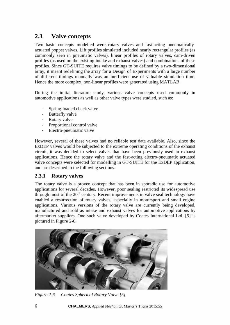
2.3.1 Rotary valves
The rotary valve is a proven concept that has been in sporadic use for automotive
applications for several decades. However, poor sealing restricted its widespread use
through most of the 20th century. Recent improvements in valve seal technology have
enabled a resurrection of rotary valves, especially in motorsport and small engine
applications. Various versions of the rotary valve are currently being developed,
manufactured and sold as intake and exhaust valves for automotive applications by
aftermarket suppliers. One such valve developed by Coates International Ltd. [5] is
pictured in Figure 2-6.
Figure 2-6 Coates Spherical Rotary Valve [5]

CHALMERS, Applied Mechanics, Master’s Thesis 2015:55 7
A rotary valve exhibits some benefits over conventional poppet valve systems, like:
- Simplicity of actuating mechanism
- Larger port areas
- Possibility to split flow into multiple paths with a single valve
However, several drawbacks are also associated with rotary valves when considering
them for application in ExDEP.
- No actual flow data available
- No existing modelling object available in GT-SUITE
- Phasing and variable opening profiles require extremely complex designs
- Timing six ExDEP profiles results in almost constantly open valve
- Unreasonably large size and packaging problems with one valve per cylinder
Since GT-SUITE does not have a rotary valve object that can directly be
implemented, the rotary valves were modelled using the OrificeConn object as in
Figure 2-7. The forward and reverse discharge coefficients of the orifices could be
varied based on crank angle and defined in an array within the object, while the
dimensions of the port can be specified as the orifice diameter (this adds some
complication when the ports have to be any shape other than circular). However this
was verified to be the best way to model a rotary valve after contacting Gamma
Technologies Inc.
Figure 2-7 Rotary valves modelled using Orifice objects in GT-SUITE

8 CHALMERS, Applied Mechanics, Master’s Thesis 2015:55
Figure 2-8 Variation of effective flow area of a) rotary valves, b) poppet valves [7]
As seen in Figure 2-8, with most normal rotary valves the discharge coefficient
linearly increases from zero as the port/window on the rotor comes across the port on
the stator.
Maximum discharge coefficient is achieved when both the ports are perfectly
superimposed on each other and then it linearly reduces to zero as the rotor port
moves past the stator port. The ports were sized based on the flow area of adjacent
components, however since no actual flow test data from rotary valves was available
the valve model created was an ‘ideal valve’ which achieved a maximum forward and
reverse discharge coefficient of unity when both the ports are perfectly superimposed.
However, actual discharge coefficients depend on port size and geometry, and seldom
reach the value of unity.
The discharge coefficient through an orifice can be described using equation (2.1) [7]
and equation (2.2) [8].
PA
mC
r
d
2 (2.1)
rde ACA (2.2)
Rudimentary CAD models of the rotary valves were prepared to assist in visualization
of packaging them next to the cylinder head, see Figure 2-9.
Figure 2-9 CAD concepts of various rotary valve configurations

CHALMERS, Applied Mechanics, Master’s Thesis 2015:55 9
One of the issues faced with rotary valves was packaging of the rotors, as in Figure 2-10. Several different packaging strategies were envisioned. Having the rotor axes
parallel to the crankshaft meant they could easily be driven off the crankshaft,
however this was a complicated way to position two independent rotors (one each for
blowdown and scavenging) at each exhaust port given their estimated sizes.
Figure 2-10 Interference in valve rotors
Also further simulations of ExDEP showed the need for independent lift timings and
open durations to obtain best results at different operating points of the engine. This
would necessitate a complex rotary valve with a moving stator port or one where the
dimensions of the stator window can be varied during operation. These challenges
along with the lack of accurate flow data for such a model meant that the rotary valve
idea had to be dropped midway through the project.

10 CHALMERS, Applied Mechanics, Master’s Thesis 2015:55
2.3.2 Fast-acting valves
The actuation of a conventional poppet valve completely independent of crankshaft
rotation is a technology that is rapidly gaining popularity in the automotive sector.
Actuation of fast valves can be implemented in several ways. One design currently
being tested with positive results for passenger car applications is by a Swedish firm
Freevalve AB (Cargine Engineering AB) [9]. The Freevalve design, as pictured in
Figure 2-11, is an electronically controlled pneumatic-hydraulic actuator that can
achieve rapid valve actuation using conventional poppet valves fully independent of
crankshaft rotation [10].
Figure 2-11 Cargine Freevalve system [10]
The Freevalve design is hydraulically damped and is hence free of the float and
bounce problems associated with cam-driven poppet valves. They have several other
benefits over conventional valves, including:
- Ability to instantly vary timing and lift for individual operating points
- Very fast actuation for almost stepped valve response, see Figure 2-12
- No drastic system redesign required. Cam-less actuation mechanisms can
drive conventional poppet valves
- Ease of implementing in GT-SUITE using existing modelling objects
However, such a system comes with its own drawbacks, including;
- Higher energy consumption than cam technology, as the pressurised air from
the actuating circuit is exhausted into ambient air [11].
- Extreme variation in operating conditions due to exhaust temperatures could
cause unpredictable and unstable behaviour of such valves due to variation of
the viscosity of hydraulic fluid with temperature [10]. However, this instability
is of reduced significance with ExDEP applications compared to in-cylinder
exhaust valves.
- Such a system would also require the design and implementation of a
dedicated electronic control system.
CHALMERS, Applied Mechanics, Master’s Thesis 2015:55 11
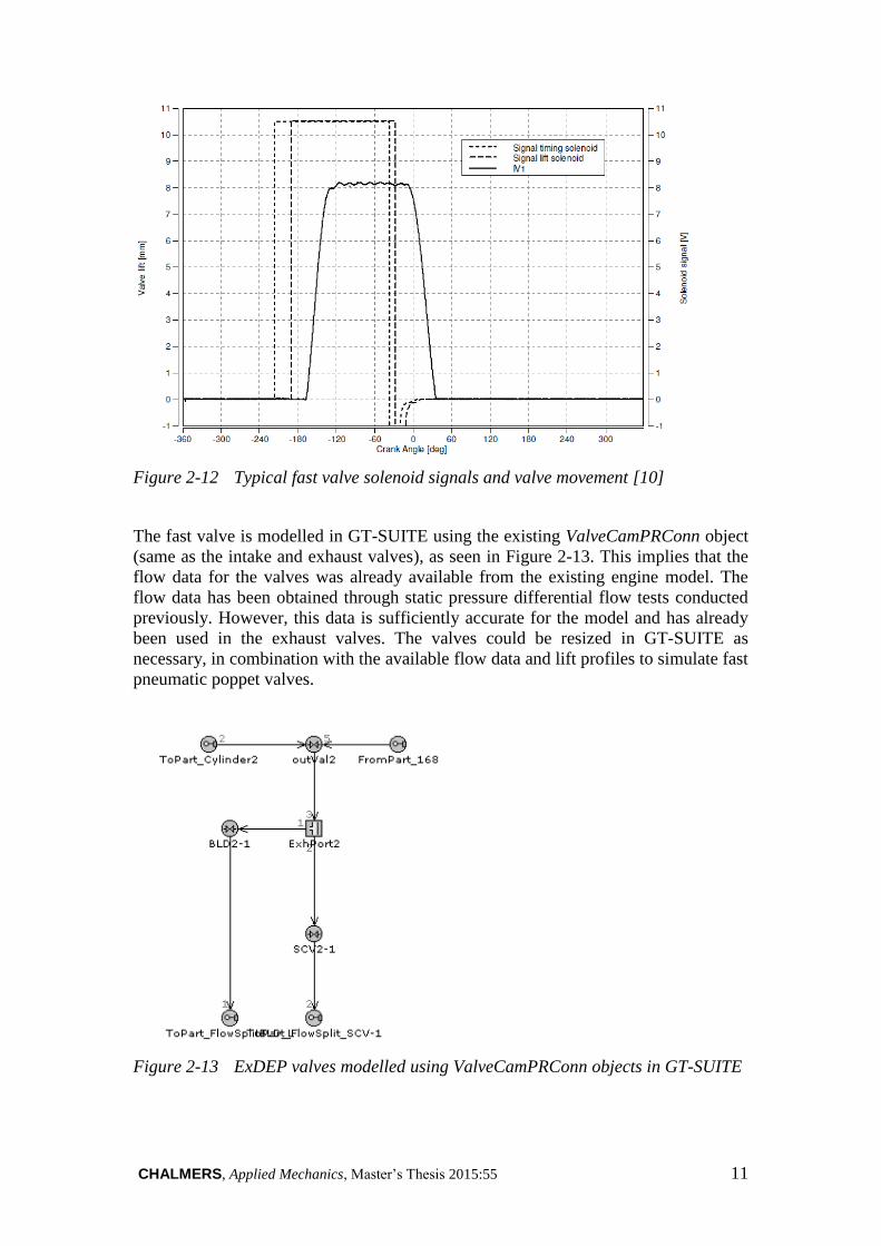
Figure 2-12 Typical fast valve solenoid signals and valve movement [10]
The fast valve is modelled in GT-SUITE using the existing ValveCamPRConn object
(same as the intake and exhaust valves), as seen in Figure 2-13. This implies that the
flow data for the valves was already available from the existing engine model. The
flow data has been obtained through static pressure differential flow tests conducted
previously. However, this data is sufficiently accurate for the model and has already
been used in the exhaust valves. The valves could be resized in GT-SUITE as
necessary, in combination with the available flow data and lift profiles to simulate fast
pneumatic poppet valves.
Figure 2-13 ExDEP valves modelled using ValveCamPRConn objects in GT-SUITE

12 CHALMERS, Applied Mechanics, Master’s Thesis 2015:55
Figure 2-14 Lift profiles defined for different valves
Since the valves are described as fast pneumatic valves, they are driven completely
independently of the crankshaft. The lift profiles defined are also idealised with
minimal deviation from actual lift behaviour, as seen in Figure 2-14.
Fully independent timing and open duration could now be achieved more easily using
these profiles. This concept comes with its own packaging requirements, which was
again checked by preparing simple CAD models of the concept in CATIA, as in
Figure 2-16.
Figure 2-16 CAD model of independently actuated poppet valves
0
0.2
0.4
0.6
0.8
1
1.2
02
95
88
71
16
14
51
74
20
32
32
26
12
90
31
93
48
37
74
06
43
54
64
49
35
22
55
15
80
60
96
38
66
76
96
No
rma
lise
d V
alv
e L
ift
Crank Angle (degrees)
BLD_lift
SCV_lift
Exhaust_lift
Intake_lift
Figure 2-15 CAD of independently actuated poppet valves

CHALMERS, Applied Mechanics, Master’s Thesis 2015:55 13
From some prior experience of engineers at Volvo it is known that the energy
consumption of current pneumatic valve mechanisms is slightly higher than that of
cam-driven mechanisms. Though this was not modelled due to a lack of actual data,
energy consumption can be easily implemented in the model when data becomes
available.
A normal cam-driven poppet valve system is difficult to implement for ExDEP due to
the short duration in which the valve is required to open fully, achieve sufficient flow
through area for the required duration, and then close. The problem is compounded
when some type of variable valve actuation/timing (VVA/VVT) mechanism is
required.
Fast-acting poppet valves can also be modelled in GT-SUITE using the object
ValveCamUserConn, This object implements a user subroutine which allows control
over the valve timing by parameterisation rather than having to change the entire
valve lift array for each experiment. However, creating this subroutine requires
knowledge of FORTRAN programming, and was thus not performed under the
limited time frame of this project. This method is utilised in another Master’s thesis
work [12] conducted at Chalmers University of Technology.
14 CHALMERS, Applied Mechanics, Master’s Thesis 2015:55
2.4 Flow path modelling
Re-design of the exhaust manifolds and flow path objects upstream of the HP turbine
was necessitated due to the introduction of ExDEP, this constitutes flow path
modelling. The only change made to flow paths downstream of HP turbine was
connection of the scavenging flow to the LP turbine inlet. Minimal changes to the
system ensure simplicity and translate to minimum redesign/re-manufacture cost in
reality.
Modelling of these components helps to understand the volume sensitivity of the
specific engine model under investigation. After the volumes of manifolds (with
sufficient cross-sectional areas) are obtained through initial simulations and after the
ExDEP valves are sized to accommodate flow under the studied operating points the
dimensions obtained are used to prepare surface models in CAD in conjunction with
packaging requirements. All CAD modelling is done using CATIA (V5-6 R2012
build 22) that allows easy modelling and visualisation of surfaces.
The models are then discretised in the GEM3D tool of GT-SUITE to obtain accurate
flow components models, which are then implemented in the object. GEM3D is able
to compute cross-sections and bends accurately, hence improving the accuracy of the
model. The difficulty with this however is that even the simplest changes in geometry
imply that the CAD model will have to be edited/updated, discretised again and then
included in the model. This consumes a significant amount of time, but reduces the
risk of having an overly simplified and unrealistic simulation model.
2.4.1 Exhaust port and valve body
The exhaust port object in the existing model is a straight pipe object, whose length
and diameter are parameterised to understand their effects on performance. During
initial stages of this project the ExDEP valve body, flow split and associated
manifolds were visualised as an add-on system as in that could be bolted onto the
cylinder head at the ports, as in Figure 2-17a. However at a later stage it was decided
that integration of the valve bodies into the cylinder head would yield best
performance due to reduction of dead volumes in the exhaust ports, as in Figure 2-17b.
This meant that the exhaust ports had to be redesigned to accommodate a valve body
based on the size and lift of each valve. GEM3D allows these changes to be
accurately represented in the model rather than having a simple pipe object with
defined length and diameter.
CHALMERS, Applied Mechanics, Master’s Thesis 2015:55 15
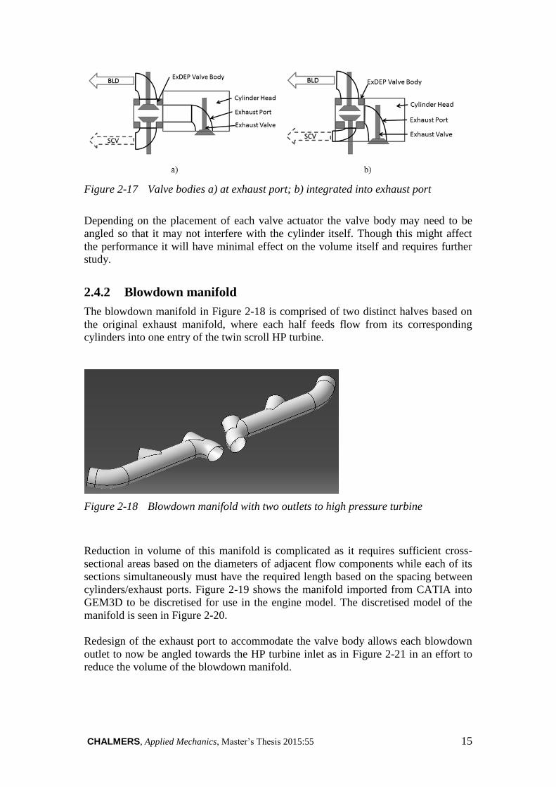
Figure 2-17 Valve bodies a) at exhaust port; b) integrated into exhaust port
Depending on the placement of each valve actuator the valve body may need to be
angled so that it may not interfere with the cylinder itself. Though this might affect
the performance it will have minimal effect on the volume itself and requires further
study.
2.4.2 Blowdown manifold
The blowdown manifold in Figure 2-18 is comprised of two distinct halves based on
the original exhaust manifold, where each half feeds flow from its corresponding
cylinders into one entry of the twin scroll HP turbine.
Figure 2-18 Blowdown manifold with two outlets to high pressure turbine
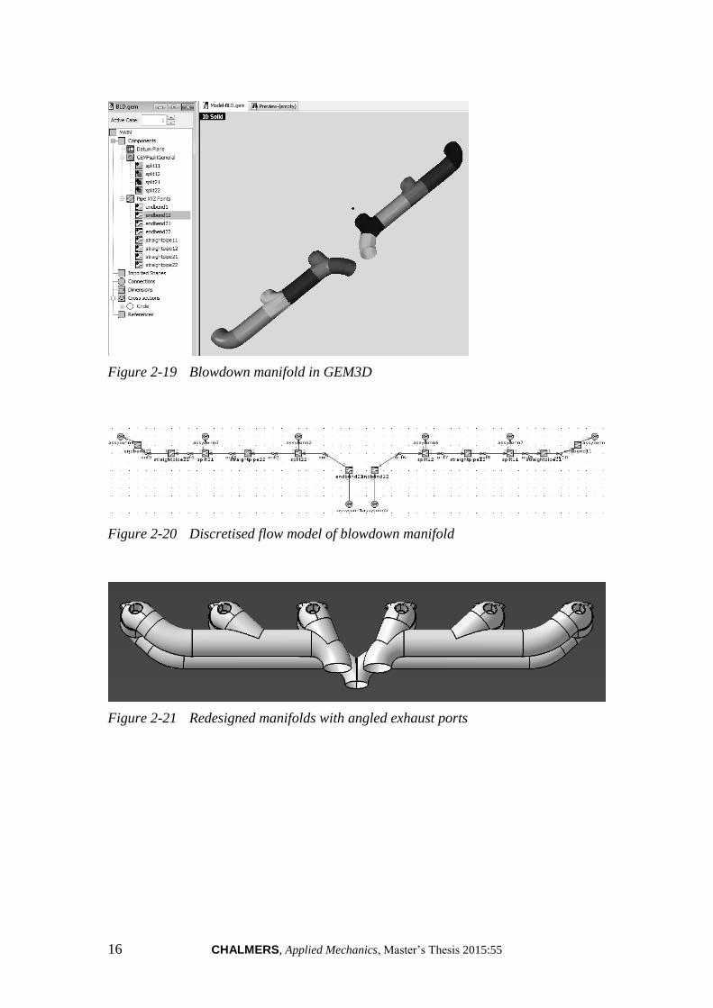
Reduction in volume of this manifold is complicated as it requires sufficient cross-
sectional areas based on the diameters of adjacent flow components while each of its
sections simultaneously must have the required length based on the spacing between
cylinders/exhaust ports. Figure 2-19 shows the manifold imported from CATIA into
GEM3D to be discretised for use in the engine model. The discretised model of the
manifold is seen in Figure 2-20.
Redesign of the exhaust port to accommodate the valve body allows each blowdown
outlet to now be angled towards the HP turbine inlet as in Figure 2-21 in an effort to
reduce the volume of the blowdown manifold.
16 CHALMERS, Applied Mechanics, Master’s Thesis 2015:55
Figure 2-19 Blowdown manifold in GEM3D
Figure 2-20 Discretised flow model of blowdown manifold
Figure 2-21 Redesigned manifolds with angled exhaust ports

CHALMERS, Applied Mechanics, Master’s Thesis 2015:55 17
2.4.3 Scavenging manifold
The scavenging manifold seen in Figure 2-22 is comprised of just one section, feeding
flow from all six cylinders to the single entry LP turbine. With progressive
simulations showing that the necessary scavenging flow is smaller than the blowdown
flow at all operating points, the scavenging valve and flow path is now comparatively
downsized resulting in a manifold with ~60% cross sectional area of the blowdown
manifold. Angling the scavenging flow outlet of the valve body toward the LP turbine
inlet further minimises the volume.
Figure 2-22 Scavenging manifold with single outlet to low pressure turbine

18 CHALMERS, Applied Mechanics, Master’s Thesis 2015:55
2.5 Single entry turbocharger
The valve timing optimisation being carried out resulted in local minima in BSFC,
where the duration of exhaust pulses from each cylinder were distinctly spaced at
each inlet to the HP turbine. After a discussion with engineers at Volvo GTT, it was
proposed that these pulses could be overlapped, as in Figure 2-23, using a single
blowdown manifold having only one outlet to a single entry turbocharger.
Figure 2-23 Pressure pulses in both halves of blowdown manifold
To further decrease the pressure fluctuation/pulse amplitude, an experiment was
conducted with a diffuser placed after each blowdown valve. In order to keep volumes
at a minimum, the diffuser length was maintained at 21.5% of the exhaust port length
with a cone angle of 8o. At the entry of the diffuser, the exhaust gas velocity is so high
that it does not possess sufficient time for diffusion using such a short diffuser.
However, an increase in diffuser length contributed more to increase in volume than
any perceivable pressure recovery in the blowdown manifold. Hence the idea of a
diffuser was dropped.
It was thought that such a manifold would create a more constant pressure flow that
could be utilised better by a single entry turbocharger, leading to larger performance
gains. A single entry turbocharger was implemented in GT-SUITE by resizing the
existing turbine and using existing data. This was tested in conjunction with a simple
diffuser/venturi added to the flow path just downstream of the blowdown valves. The
cone angle of the diffuser was restricted to 7 degrees [13] to have maximum
efficiency without flow separation, which may not be simulated properly in GT-
SUITE. The length of the diffuser was also kept to a minimum (nearly equal to its
inlet diameter) in order to minimize volume.
The investigation revealed benefits at two of the five chosen operating points.
However, further investigation with a calibrated model of a single entry turbocharger
is required to verify possible benefits.

CHALMERS, Applied Mechanics, Master’s Thesis 2015:55 19
3 Simulation
All simulations are performed using GT-SUITE v.7.2 flow simulation tool used at the
Advanced Technology and Research centre of Volvo GTT. This is a one-dimensional
fluid dynamics software that uses the Navier-Stokes equation in conjunction with
empirical data, maps and look-up tables to compute averaged flow parameters across
flow direction [3]. The following sections describe the method in which simulations
were conducted on the ExDEP model.
3.1 Operating points
A total of five operating points of the engine were chosen for all simulations: three at
low engine speeds and two at moderately higher engine speeds. The points chosen are
described in Table 1.
Table 1 Engine operating points chosen for simulation
Point Speed [rpm] Load [%] Comment
A 1100 37 Road-load conditions
B 1100 56.6
C 1100 100 Max. Torque demand for gradeability, etc.
D 1600 59 Gear shifting
E 1600 100
3.2 Simulation method
For the initial simulations on each model, the dimensions of all additional flow
components (which do not exist in the base model) such as diameters, lengths,
volumes and surface areas were approximated based on necessary flow areas and
dimensions of adjacent flow components. Many of these dimensions were
parameterised and varied in sweeps to observe their individual influence on the
performance of the system.
Despite the actual engine using two exhaust valves per cylinder, the original engine
model contained only one exhaust valve per cylinder, using a flow multiplier to
simulate the two-valve setup. However during the later stages of this thesis when the
exhaust port geometry was altered and the port object was updated in the model from
CAD, an additional valve was added per cylinder. The base model with one exhaust
valve was also updated to have two valves at first to eliminate discrepancy in
simulation results. However, the accuracy of the exhaust port itself was improved in
the ExDEP models compared to the simple pipe object used in the base model.
Simulations are performed to get each parameter’s optimum at each operating point.
Optimum turbine mass multipliers are found for each point. However, such localised
optimisation of turbine mass multipliers is unrealistic. The turbine is thus resized
uniformly based on the rescaling at the operating point that shows maximum gains.

20 CHALMERS, Applied Mechanics, Master’s Thesis 2015:55
A general simulation methodology consists of the procedure below:
- Parameterise dimension/geometry of existing upstream flow components
- Vary these parameters individually in sweeps to find optimum
- Investigate closest realistic geometry in CAD
- Create CAD
- Update parameters in simulation model and reiterate
- Find suitable geometry that yields benefits at all points
3.3 Parameters
The following parameters were varied independently to study their influence on the
performance of the system:
- BLD open (start of EVO to fully open, steps of 5 crank angle degrees)
- BLD close (exhaust valve fully open to EVC, steps of 5 crank angle degrees)
- SCV open (exhaust valve fully open to EVC, steps of 5 crank angle degrees)
- SCV close (exhaust valve fully open to EVC, steps of 5 crank angle degrees)
- BLD diameter (100-160% of exhaust valve diameter, steps of 30%)
- SCV diameter (100-160% of exhaust valve diameter, steps of 30%)
- Exhaust port length (100-60% of exhaust port length, steps of 10%)
- HP Turbine mass multiplier (50-200% of original turbine size)
- LP Turbine mass multiplier (50-200% of original turbine size)
3.4 Performance parameters
The BSFC of the engine model is monitored for all simulations as this is a good gauge
of the efficiency of any engine. Brake specific fuel consumption is the mass flow rate
of fuel used per unit brake power, as in equation (3.1).
𝐵𝑆𝐹𝐶 [𝑔
𝑘𝑊ℎ] =
��𝑓
𝐵𝑃
[𝑔/ℎ]
[𝑘𝑊]
(3.1)
Though the BSFC of the engine model is mainly observed to gauge its performance,
other parameters are recorded in an attempt to fully understand the effects of ExDEP.
These include:
- Crankshaft attachment power– power obtained from turbocompound shaft
- Mean effective pressures (BMEP, PMEP, AMEP)
- Cylinder pressure

CHALMERS, Applied Mechanics, Master’s Thesis 2015:55 21
4 Results
4.1 Observations
Before discussion of the main results the following observations made during
experiments will help understand why the necessary changes were made to the
model/architecture.
4.1.1 Volume sensitivity of the model
Increase in the flow path volume upstream of the HP and LP turbines proportionally
deteriorates the fuel consumption, seen in Figure 4-1. Hence volumes were minimized
wherever possible. The variation of pressure and velocity with changing these
volumes is shown in Figure 4-2. This proved especially challenging at the manifolds
since a lower volume is desirable without having lower cross section (which will
reduce flow through area and affect the mass flow rates). Also around the ExDEP
valve body this is particularly challenging to obtain sufficient flow area for the valves,
but not have them so compact that flow chokes.
Figure 4-1 Change in BSFC with ExDEP manifold volumes
Figure 4-2 Variation of exhaust pressure and velocity at inlet of HP turbine
0
0.05
0.1
0.15
0.2
0.25
0.3
0.35
0.4
% B
SF
C c
ha
ng
e
10% increase BLD volume
20% increase BLD volume
30% increase BLD volume
10% increase BLD & SCV volume
20% increase BLD & SCV volume
30% increase BLD & SCV volume
10% increase SCV volume
20% increase SCV volume
30% increase SCV volume
-0.5
0.0
0.5
1.0
1.5
2.0
0 1 2 3 4 5 6 7 8 9 10
% C
ha
ng
e
Average total pressureHPT inlet x100
Average velocity HPTinlet

22 CHALMERS, Applied Mechanics, Master’s Thesis 2015:55
4.1.2 Exhaust port length
Reducing the length of the exhaust port improves the engine performance as in Figure 4-3, which is again a consequence of reduction in volumes upstream of the turbines.
The effect of exhaust port length is verified by parameterizing the length of the
exhaust port object and varying it with all other parameters kept constant. This led to
the idea of having the ExDEP flow split and valve body within the exhaust port itself.
This brings about some more new packaging challenges within the cylinder head and
will require redesign of the cylinder head.
Figure 4-4 shows the variation of rate of convective heat transfer with changing
exhaust port length, relative to the base model. This implies that the exhaust gas
exiting the port contains a larger fraction of thermal energy that can be utilized for
expansion in the turbine.
Figure 4-3 Variation in BSFC with exhaust port length
Figure 4-4 Variation in rate of convective heat transfer with exhaust port length
-1.4
-1.2
-1
-0.8
-0.6
-0.4
-0.2
0
BS
FC
Ch
an
ge
(%
)
10% reduced Exhaust port length
20% reduced Exhaust port length
30% reduced Exhaust port length
40% reduced Exhaust port length
-40
-35
-30
-25
-20
-15
-10
-5
0
0 10 20 30 40 50
Av
era
ge
Co
nv
ect
ive
He
at
tra
nsf
er
rate
to
wa
lls(
%
cha
ng
e)
Reduction in exhaust port length (%)

CHALMERS, Applied Mechanics, Master’s Thesis 2015:55 23
4.1.3 Routing of scavenging flow
When the scavenging exhaust flow is directed to the LP turbine, a substantial gain in
shaft power is obtained at the expense of increased back-pressure, seen in Figure 4-5.
Discussions with Volvo engineers revealed that this increase in shaft power by
diverting some part of the expansion to the LP turbine of the model is not always
accurate and the actual gain may be as low as 50% of calculated increase, but this is
still a large gain. This led to a change in model architecture where the scavenging
flow was then fed to the LP turbine instead of directly being exhausted.
Figure 4-5 Variation of BSFC and attachment power with SCV flow diversion to
exhaust
0
10
20
30
40
50
60
70
80
90
A B C D E
Ch
an
ge
(%
)
Operating Points
BSFC increase
Attachment Power Decrease

24 CHALMERS, Applied Mechanics, Master’s Thesis 2015:55
4.1.4 ExDEP valve diameters
To begin with the valve diameters on the ExDEP valves were 1.6 times the diameter
of the exhaust valves as this provided the best flow characteristics. However during
simulation, a 10% increase in the diameters of the ExDEP valves over the diameter of
the exhaust valve decreased the BSFC by nearly 0.3g/kWh. The valve diameters were
progressively reduced to obtain a compromise between performance and packaging
requirements. The valve diameters in Figure 4-6 and Figure 4-7 are expressed as a
percentage of the exhaust valve diameter.
Figure 4-6 Variation of BSFC with ExDEP valve diameters
Figure 4-7 Variation of mass flow rate through ExDEP valves with valve diameters
-0.6
-0.5
-0.4
-0.3
-0.2
-0.1
0
1 2 3 4 5 6 7
BS
FC
Ch
an
ge
(%
)
-2.5
-2
-1.5
-1
-0.5
0
0.5
1
1.5
2
0 1 2 3 4 5 6 7 8
% M
ass
flo
w r
ate
ch
an
ge
Average mass flow ratethrough BLD valve
Average mass flow ratethrough SCV valve
1 - 100% BLD & SCV dia
2 - 130% BLD & 100% SCV dia
3 - 160% BLD & 100% SCV dia
4 - 100% BLD & 130% SCV dia
5 - 100% BLD & 160% SCV dia
6 - 130% BLD & SCV dia
7 - 160% BLD & SCV dia

CHALMERS, Applied Mechanics, Master’s Thesis 2015:55 25
4.2 Simulation results
This section presents the results of the final ExDEP model implemented on the Volvo
HDE13 engine. Parameter sweeps were focused at obtaining benefits primarily at
operating points A and B, as these points are closest to averaged data of the European
Transient Cycle (ETC) [14]. The ExDEP valve diameters used in the final simulations
are 140% of the exhaust valve diameter.
4.2.1 Brake Specific Fuel Consumption (BSFC)
Figure 4-8 shows that an improvement in BSFC of the ExDEP architecture is obtained
at all chosen operating points. Though primary gains are at medium loads for both the
operating speeds chosen, there exist minor gains at low and high loads as well. A
significant observation is that the existing engine components were designed to target
gains at these points. Resizing of components (e.g.: exhaust manifolds, exhaust valve
diameters) could shift the points of maximum gains towards the lower end of the load
range.
Figure 4-8 BSFC improvements of studied load points of ExDEP architecture over
base engine
0
1
2
3
4
5
6
7
A B C D E
BS
FC
De
cre
ase
(%
)
Operating Points
26 CHALMERS, Applied Mechanics, Master’s Thesis 2015:55
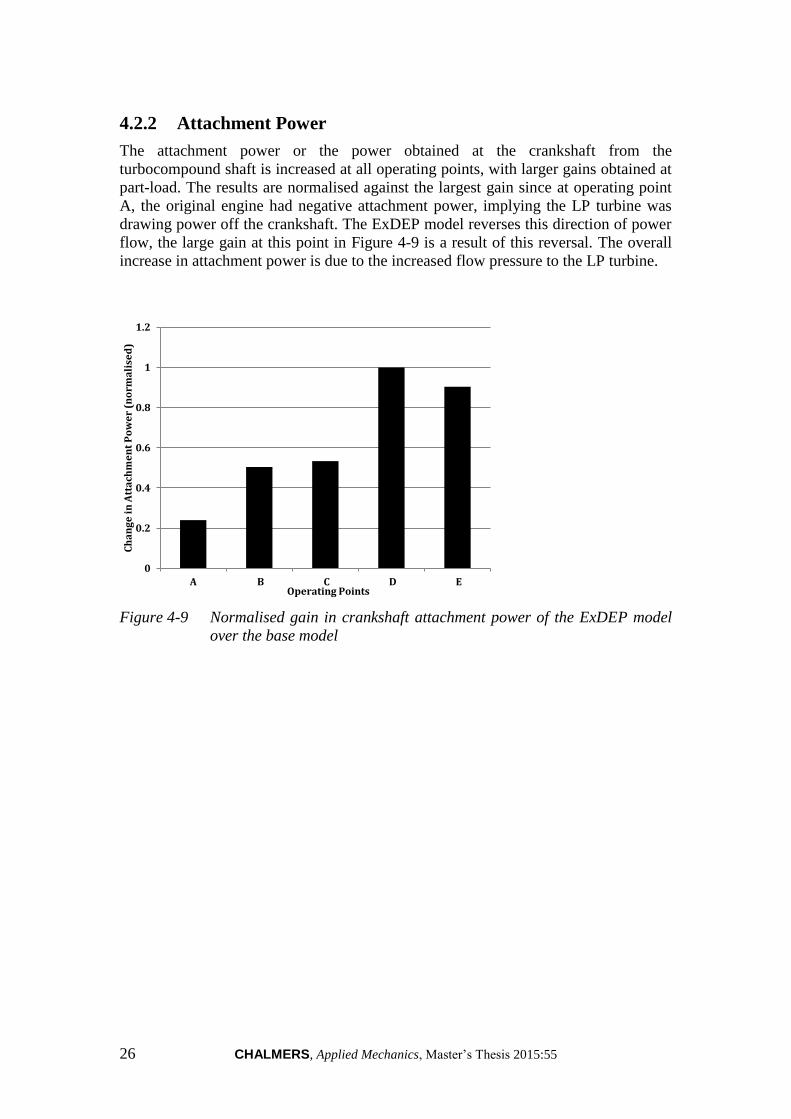
4.2.2 Attachment Power
The attachment power or the power obtained at the crankshaft from the
turbocompound shaft is increased at all operating points, with larger gains obtained at
part-load. The results are normalised against the largest gain since at operating point
A, the original engine had negative attachment power, implying the LP turbine was
drawing power off the crankshaft. The ExDEP model reverses this direction of power
flow, the large gain at this point in Figure 4-9 is a result of this reversal. The overall
increase in attachment power is due to the increased flow pressure to the LP turbine.
Figure 4-9 Normalised gain in crankshaft attachment power of the ExDEP model
over the base model
0
0.2
0.4
0.6
0.8
1
1.2
A B C D E
Ch
an
ge
in
Att
ach
me
nt
Po
we
r (n
orm
ali
sed
)
Operating Points
CHALMERS, Applied Mechanics, Master’s Thesis 2015:55 27
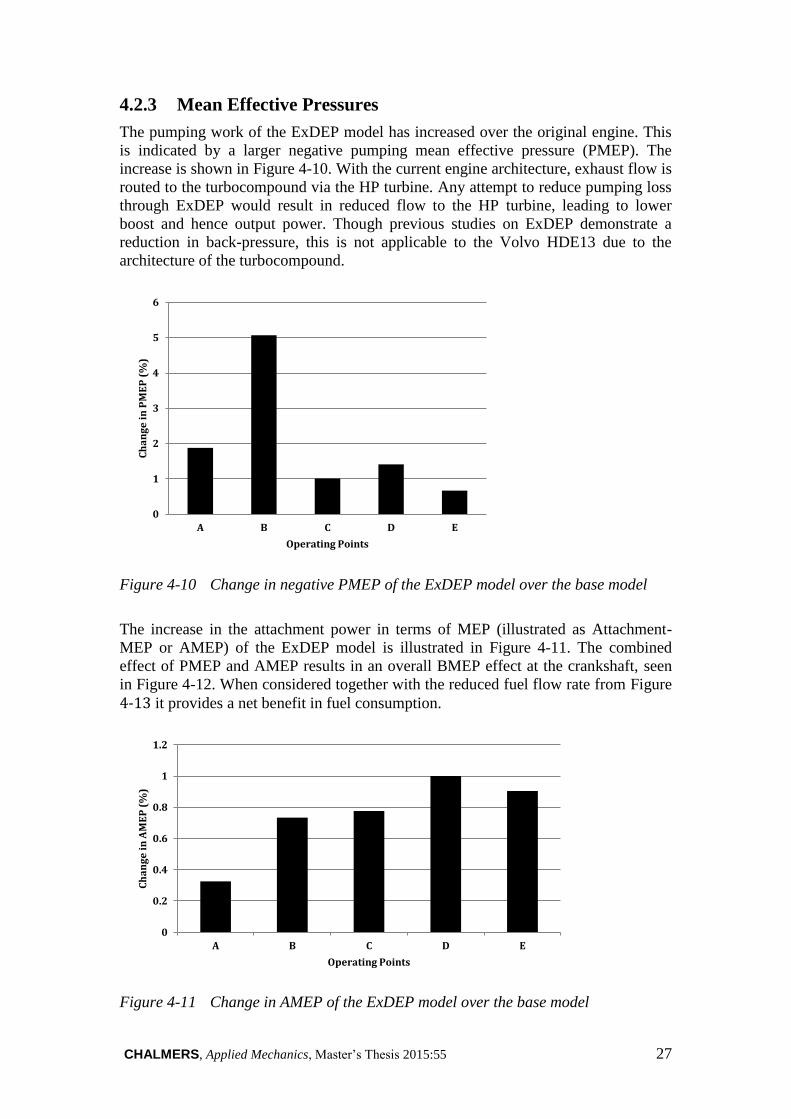
4.2.3 Mean Effective Pressures
The pumping work of the ExDEP model has increased over the original engine. This
is indicated by a larger negative pumping mean effective pressure (PMEP). The
increase is shown in Figure 4-10. With the current engine architecture, exhaust flow is
routed to the turbocompound via the HP turbine. Any attempt to reduce pumping loss
through ExDEP would result in reduced flow to the HP turbine, leading to lower
boost and hence output power. Though previous studies on ExDEP demonstrate a
reduction in back-pressure, this is not applicable to the Volvo HDE13 due to the
architecture of the turbocompound.
Figure 4-10 Change in negative PMEP of the ExDEP model over the base model
The increase in the attachment power in terms of MEP (illustrated as Attachment-
MEP or AMEP) of the ExDEP model is illustrated in Figure 4-11. The combined
effect of PMEP and AMEP results in an overall BMEP effect at the crankshaft, seen
in Figure 4-12. When considered together with the reduced fuel flow rate from Figure 4-13 it provides a net benefit in fuel consumption.
Figure 4-11 Change in AMEP of the ExDEP model over the base model
0
1
2
3
4
5
6
A B C D E
Ch
an
ge
in
PM
EP
(%
)
Operating Points
0
0.2
0.4
0.6
0.8
1
1.2
A B C D E
Ch
an
ge
in
AM
EP
(%
)
Operating Points

28 CHALMERS, Applied Mechanics, Master’s Thesis 2015:55
Figure 4-12 Change in BMEP of the ExDEP model over the base model
Figure 4-13 Decreased fuel mass flow rate of the ExDEP model over the base model
-0.15
-0.1
-0.05
0
0.05
0.1
0.15
0.2
0.25
A B C D E
Ch
an
ge
in
BM
EP
(%
)
Operating Points
-7
-6
-5
-4
-3
-2
-1
0
A B C D E
Ch
an
ge
in
fu
el
ma
ss f
low
ra
te (
%)
Operating Points
CHALMERS, Applied Mechanics, Master’s Thesis 2015:55 29
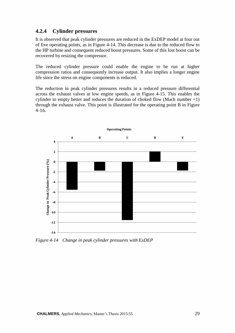
4.2.4 Cylinder pressures
It is observed that peak cylinder pressures are reduced in the ExDEP model at four out
of five operating points, as in Figure 4-14. This decrease is due to the reduced flow to
the HP turbine and consequent reduced boost pressures. Some of this lost boost can be
recovered by resizing the compressor.
The reduced cylinder pressure could enable the engine to be run at higher
compression ratios and consequently increase output. It also implies a longer engine
life since the stress on engine components is reduced.
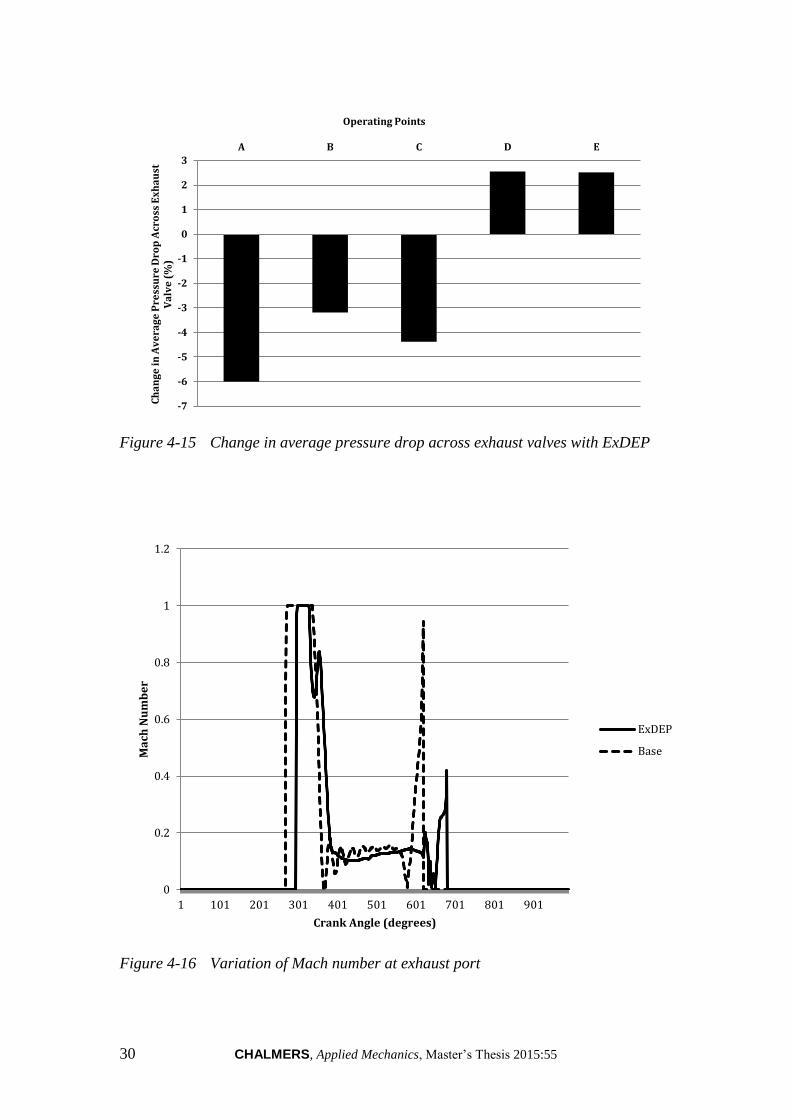
The reduction in peak cylinder pressures results in a reduced pressure differential
across the exhaust valves at low engine speeds, as in Figure 4-15. This enables the
cylinder to empty better and reduces the duration of choked flow (Mach number =1)
through the exhaust valve. This point is illustrated for the operating point B in Figure 4-16.
Figure 4-14 Change in peak cylinder pressures with ExDEP
-14
-12
-10
-8
-6
-4
-2
0
2
4
A B C D E
Ch
an
ge
in
Pe
ak
Cy
lin
de
r P
ress
ure
(%
)
Operating Points
30 CHALMERS, Applied Mechanics, Master’s Thesis 2015:55
Figure 4-15 Change in average pressure drop across exhaust valves with ExDEP
Figure 4-16 Variation of Mach number at exhaust port
-7
-6
-5
-4
-3
-2
-1
0
1
2
3
A B C D EC
ha
ng
e i
n A
ve
rag
e P
ress
ure
Dro
p A
cro
ss E
xh
au
st
Va
lve
(%
)
Operating Points
0
0.2
0.4
0.6
0.8
1
1.2
1 101 201 301 401 501 601 701 801 901
Ma
ch N
um
be
r
Crank Angle (degrees)
ExDEP
Base

CHALMERS, Applied Mechanics, Master’s Thesis 2015:55 31
5 Conclusions
The modelling and simulation carried out as a part of this project provide conclusions
that ExDEP benefits the studied turbocompound engine at the studied operating
points. The major gain, obtained at lower load and speed ranges, is from added power
at the turbocompound shaft. This gain must be verified through further work.
Routing exhaust flow at higher pressure directly to the LP turbine of the present
architecture causes a reduction in flow to the HP turbine. This results in reduced boost
and hence less cylinder output. Prior work [3] has avoided this issue by providing
constant boost using a compressor driven directly off the crankshaft. However,
preserving system architecture and parameters to the largest extent possible implies
that such modifications are not possible in this project. Yet the current ExDEP
architecture suggested requires modifications to the cylinder head and exhaust
manifolds, and selection of suitably sized turbines.
The cam-less valve system used in this model allows valve timing to be varied
continuously during transient operation of the engine. However, the studied operating
points reveal that not much variability is necessary. A full transient simulation with
varying valve lifts and durations will provide a better understanding of whether such a
system can be replaced by a simpler actuation mechanism.
The system provides overall benefits over a conventional turbocompound engine
while avoiding the drawbacks of DEP, i.e.: reduced flow area at exhaust valves and
highly choked flow at high engine speeds which greatly impedes cylinder emptying.
However, the currently implemented system causes a larger pumping loss due to
increased exhaust back pressure caused by routing flow at higher pressure to the LP
turbine. This is offset by the gains in power obtained from the turbocompound shaft.
An overall improvement in fuel consumption is a consequence of conservation of the
high pressure in the exhaust and better utilisation of both turbines through rescaling.

32 CHALMERS, Applied Mechanics, Master’s Thesis 2015:55
CHALMERS, Applied Mechanics, Master’s Thesis 2015:55 33
6 Future work
Transient operation
Though the implemented ExDEP architecture shows benefits at the five studied
operating points, an increase in resolution and transient engine simulations could
provide a better understanding of the real-world operation of this system.
Refinement of valve profiles
The ExDEP valve profiles used in this project are idealised for simplicity. However,
actual data of fast-acting valves can be utilised together with scripting to refine and
automate the simulation and obtain more realistic results.
Exhaust gas recirculation
Discussions with engineers at Volvo GTT showed that the ExDEP model carried
sufficient exhaust pressure to drive the EGR circuit.
Emission benefits
A cursory glance at simulation results showed promising reduction in NOx,
Hydrocarbon and CO2 emissions. However, this was not the primary objective of this
project, and can be analysed in greater detail.
Variable geometry turbine
Investigation of running a fixed geometry turbine (lower cost) using ExDEP valves to
vary the flow instead.
Exhaust valve timing
During this project, the timing of the exhaust valves was retained as in the base
model. The effect of varying this timing along with ExDEP could reveal further
benefits.
Engine braking
Though the base model used for this project was equipped with a cam-driven engine
brake, the use of ExDEP valves for engine braking can be investigated.

34 CHALMERS, Applied Mechanics, Master’s Thesis 2015:55

CHALMERS, Applied Mechanics, Master’s Thesis 2015:55 35
7 References
[1] European Commission (2013): Horizon 2020 - Work Programme 2014-2015 –
Smart, Green and Integrated Transport, Horizon 2020 Newsroom, 2014
[2] Gundmalm, S., Cronhjort A., Ångström H.E., “Divided Exhaust Period on
Heavy-Duty Diesel Engines,” presented at THIESEL 2012, Spain, Sep. 11-14,
2012.
[3] Aghaali, H., (2014): Exhaust Heat Utilisation and Losses in Internal
Combustion Engines with Focus on the Gas Exchange System. Doctoral Thesis,
KTH Royal Institute of Technology, Stockholm.
[4] Aghaali, H., Ångström, H.E., “Externally Divided Exhaust Period on a
Turbocompound Engine for Fuel-Saving”. 9th International MTZ Conference,
Heavy-Duty, On- and Off-Highway Engines, Nov. 2014.
[5] The Coates Spherical Rotary Valve (CSRV), accessed June 2015, URL
http://www.coatesengine.com/csrv-system.html
[6] Hunter, M. (1946): Rotary Valve Engines, 1st edition. J. Wiley & Sons
[7] White, F (2003) Fluid Mechanics, 7th Edition. McGraw-Hill.
[8] Heywood, J.B. (1988): Internal Combustion Engine Fundamentals, McGraw-
Hill International Edition
[9] FreeValve Technology, accessed June 2015, URL
http://www.freevalve.com/technology/free-valve-technology/
[10] Gundersen, Ø. (2009): Free Valve Technology – Development of a control
system for an electronically controlled pneumatic-hydraulic valve actuation
system for an automotive engine, Master of Science Thesis, Industrial
Engineering and Management, KTH Royal Institute of Technology, Publication
no. MMK 2009:75 MFM130, Stockholm, Sweden, 2009.
[11] Osborne, R.J. et al (2005): “Development of a Two-Stroke/Four-Stroke
Switching Gasoline Engine – The 2/4SIGHT Concept”, SAE International
2005-01-1137, 2005 SAE World Congress, Detroit, Michigan, 2005
[12] Brown, E., Carlson, D., (2015): Study of Alternative Valvetrains for Heavy-Duty
CI Engines, Master of Science Thesis, Department of Applied Mechanics,
Chalmers University of Technology, Master’s Thesis no. 2015:17, Göteborg,
Sweden, 2015.
[13] Dixon, L.S. (2005) Fluid Mechanics and Thermodynamics of Turbomachinery,
5th Edition. Butterworth-Heinemann.
[14] European Transient Cycle (ETC), accessed June 2015, URL
https://www.dieselnet.com/standards/cycles/etc.php