Embed Size (px)
Citation preview

Table of Contents
1 Welcome ............................................................................................................ 1
2 Why Control Lighting? ........................................................................................ 2
3 Control Strategies ............................................................................................... 3
4 Strategy Decisions ............................................................................................. 4
5 Strategies by Application .................................................................................... 5
6 Controls and Light Sources ................................................................................ 7
7 Energy Code Compliance................................................................................... 9
8 Lighting Control Devices..................................................................................... 12
9 Control Wiring..................................................................................................... 14
10 Control Zoning .................................................................................................... 16
11 Commissioning ................................................................................................... 18
12 Light Reduction Control using Occupancy Sensors ........................................... 21
CLTC Research .................................................................................................. 22
U.S. Department of Energy Research ................................................................ 24
Detection Methods ............................................................................................. 25
PIR Sensors ................................................................................................ 25
Microwave ................................................................................................... 25
Camera (video) ............................................................................................ 25
Standalone Versus Centrally Controlled Systems .............................................. 26
Switching and Dimming ...................................................................................... 26
Mounting............................................................................................................. 27
Coverage ............................................................................................................ 28
Field of View ................................................................................................ 28
Coverage Pattern ........................................................................................ 28
Exposure to Environmental Elements ................................................................ 29
Calibration .......................................................................................................... 30
Acceptance Testing ............................................................................................ 31
General Specifications ....................................................................................... 32
Occupancy Sensor Specification Parameters .................................................... 32
1
Exterior Lighting Control Guidance
Welcome
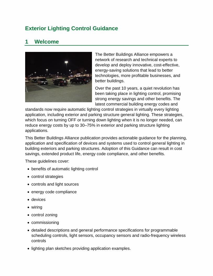
The Better Buildings Alliance empowers a network of research and technical experts to develop and deploy innovative, cost-effective, energy-saving solutions that lead to better technologies, more profitable businesses, and better buildings.
Over the past 10 years, a quiet revolution has been taking place in lighting control, promising strong energy savings and other benefits. The latest commercial building energy codes and
standards now require automatic lighting control strategies in virtually every lighting application, including exterior and parking structure general lighting. These strategies, which focus on turning OFF or turning down lighting when it is no longer needed, can reduce energy costs by up to 30–75% in exterior and parking structure lighting applications.
This Better Buildings Alliance publication provides actionable guidance for the planning, application and specification of devices and systems used to control general lighting in building exteriors and parking structures. Adoption of this Guidance can result in cost savings, extended product life, energy code compliance, and other benefits.
These guidelines cover:
benefits of automatic lighting control
control strategies
controls and light sources
energy code compliance
devices
wiring
control zoning
commissioning
detailed descriptions and general performance specifications for programmable scheduling controls, light sensors, occupancy sensors and radio-frequency wireless controls
lighting plan sketches providing application examples.

SAVE ENERGY
EXTEND PRODUCT LIFE
SECURITY
MANAGE YOUR ASSET
2 Why Control Lighting?
Automatic controls can provide several major benefits to owners of exterior and parking structure lighting systems, including substantial energy and maintenance cost savings.
Lighting controls ensure that light is used only when it is needed and in the quantity needed, generating energy cost savings that increase profitability.
COMPLY WITH CODE The latest commercial building energy codes and standards require aggressive control of exterior lighting. Exterior lighting must now be capable of turning OFF or reducing power during times of night when it is not being used.
Dimming can significantly extend the useful life of light-emitting diode (LED) lighting, increasing its value.
By maintaining a majority of lighting at a lower light and power level afterhours, the presence of people is made more detectable as luminaires in occupied areas rise to full output.
Some solutions monitor controlled lighting, providing information useful for energy analysis and maintenance.
3 Control Strategies
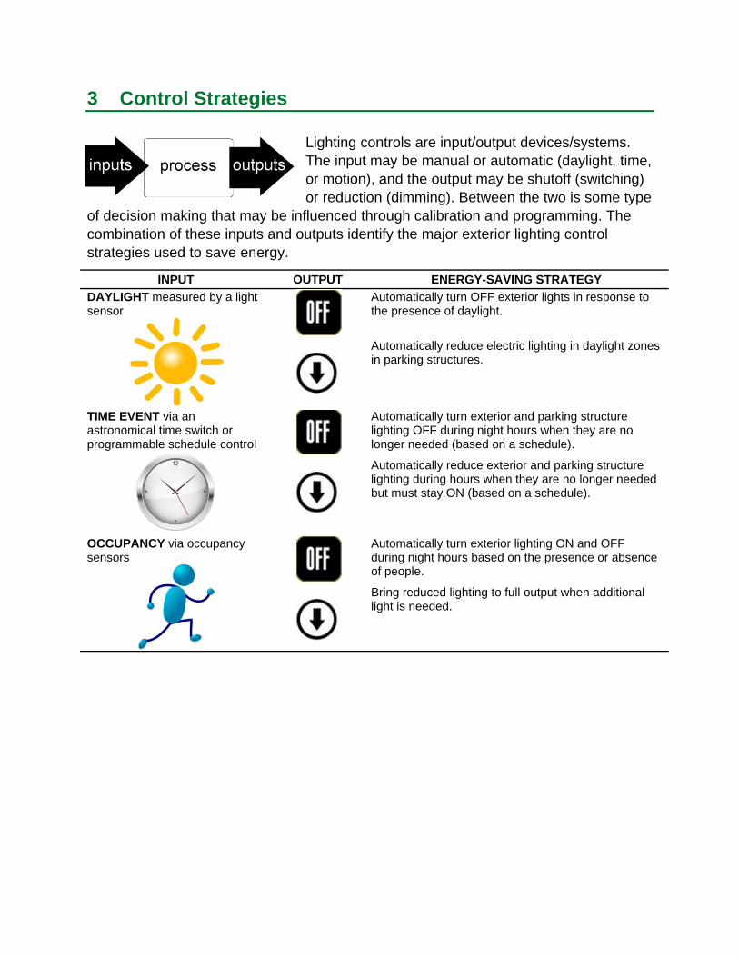
Lighting controls are input/output devices/systems. The input may be manual or automatic (daylight, time, or motion), and the output may be shutoff (switching) or reduction (dimming). Between the two is some type
of decision making that may be influenced through calibration and programming. The combination of these inputs and outputs identify the major exterior lighting control strategies used to save energy.
INPUT OUTPUT ENERGY-SAVING STRATEGY
DAYLIGHT measured by a light sensor
Automatically turn OFF exterior lights in response to the presence of daylight.
Automatically reduce electric lighting in daylight zones in parking structures.
TIME EVENT via an astronomical time switch or programmable schedule control
Automatically turn exterior and parking structure lighting OFF during night hours when they are no longer needed (based on a schedule).
Automatically reduce exterior and parking structure lighting during hours when they are no longer needed but must stay ON (based on a schedule).
OCCUPANCY via occupancy sensors
Automatically turn exterior lighting ON and OFF during night hours based on the presence or absence of people.
Bring reduced lighting to full output when additional light is needed.
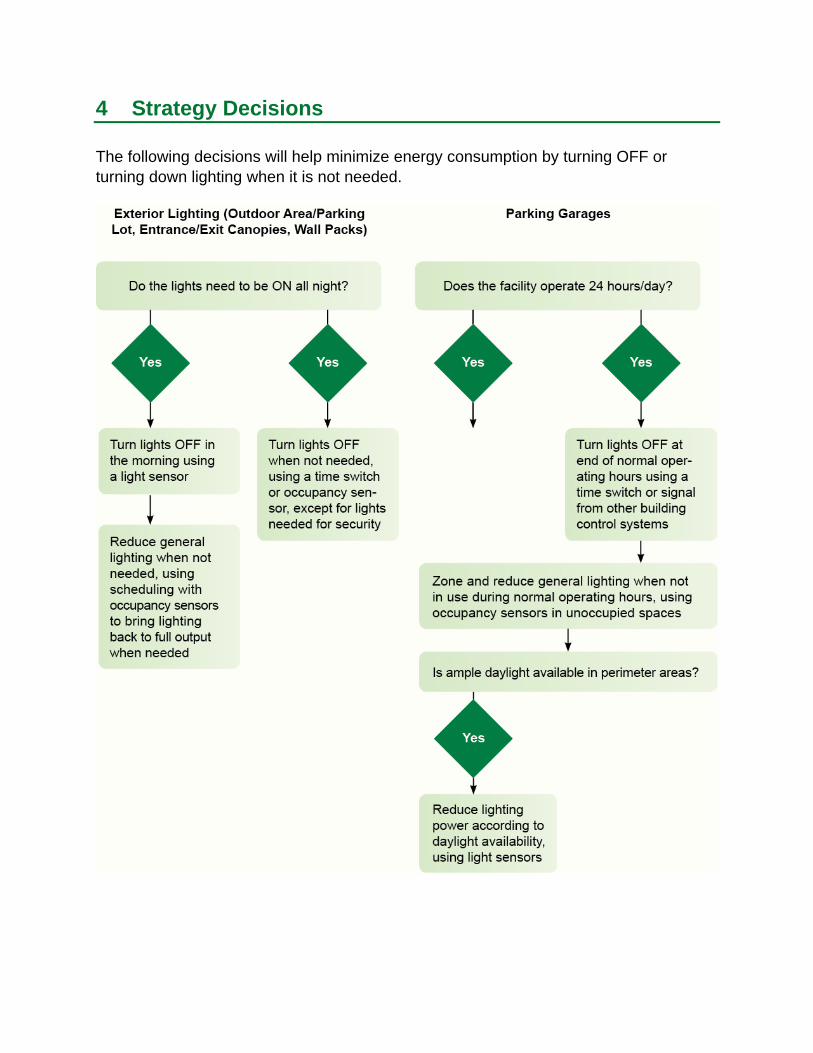
4 Strategy Decisions
The following decisions will help minimize energy consumption by turning OFF or turning down lighting when it is not needed.
5 Strategies by Application
Various automatic control strategies are ideally suited to different exterior and parking structure lighting applications.
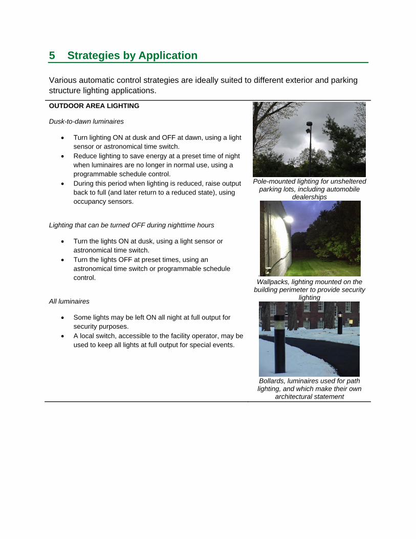
OUTDOOR AREA LIGHTING
Dusk-to-dawn luminaires
Turn lighting ON at dusk and OFF at dawn, using a light sensor or astronomical time switch.
Reduce lighting to save energy at a preset time of night when luminaires are no longer in normal use, using a programmable schedule control.
During this period when lighting is reduced, raise output back to full (and later return to a reduced state), using occupancy sensors.
Lighting that can be turned OFF during nighttime hours
Turn the lights ON at dusk, using a light sensor or astronomical time switch.
Turn the lights OFF at preset times, using an astronomical time switch or programmable schedule control.
All luminaires
Some lights may be left ON all night at full output for security purposes.
A local switch, accessible to the facility operator, may be used to keep all lights at full output for special events.
Pole-mounted lighting for unsheltered parking lots, including automobile
dealerships
. Wallpacks, lighting mounted on the
building perimeter to provide security lighting
Bollards, luminaires used for path lighting, and which make their own
architectural statement
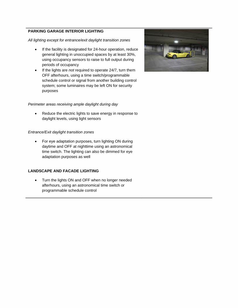
PARKING GARAGE INTERIOR LIGHTING
All lighting except for entrance/exit daylight transition zones
If the facility is designated for 24-hour operation, reduce general lighting in unoccupied spaces by at least 30%, using occupancy sensors to raise to full output during periods of occupancy
If the lights are not required to operate 24/7, turn them OFF afterhours, using a time switch/programmable schedule control or signal from another building control system; some luminaires may be left ON for security purposes
Perimeter areas receiving ample daylight during day
Reduce the electric lights to save energy in response to daylight levels, using light sensors
Entrance/Exit daylight transition zones
For eye adaptation purposes, turn lighting ON during daytime and OFF at nighttime using an astronomical time switch. The lighting can also be dimmed for eye adaptation purposes as well
LANDSCAPE AND FACADE LIGHTING
Turn the lights ON and OFF when no longer needed afterhours, using an astronomical time switch or programmable schedule control
6 Controls and Light Sources
Different types of light sources offer characteristics with varying degrees of compatibility with automatic lighting controls.
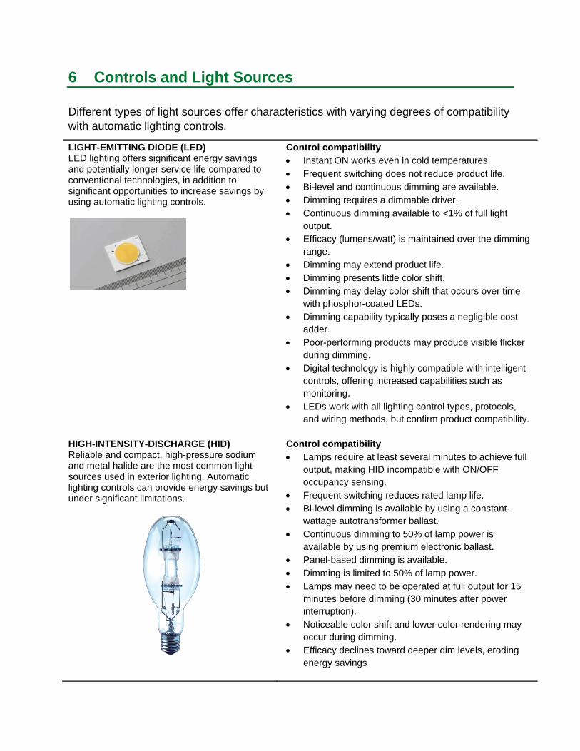
LIGHT-EMITTING DIODE (LED) LED lighting offers significant energy savings and potentially longer service life compared to conventional technologies, in addition to significant opportunities to increase savings by using automatic lighting controls.
HIGH-INTENSITY-DISCHARGE (HID) Reliable and compact, high-pressure sodium and metal halide are the most common light sources used in exterior lighting. Automatic lighting controls can provide energy savings but under significant limitations.
Control compatibility Instant ON works even in cold temperatures. Frequent switching does not reduce product life. Bi-level and continuous dimming are available. Dimming requires a dimmable driver. Continuous dimming available to <1% of full light
output. Efficacy (lumens/watt) is maintained over the dimming
range. Dimming may extend product life. Dimming presents little color shift. Dimming may delay color shift that occurs over time
with phosphor-coated LEDs. Dimming capability typically poses a negligible cost
adder. Poor-performing products may produce visible flicker
during dimming. Digital technology is highly compatible with intelligent
controls, offering increased capabilities such as monitoring.
LEDs work with all lighting control types, protocols, and wiring methods, but confirm product compatibility.
Control compatibility Lamps require at least several minutes to achieve full
output, making HID incompatible with ON/OFF occupancy sensing.
Frequent switching reduces rated lamp life. Bi-level dimming is available by using a constant-
wattage autotransformer ballast. Continuous dimming to 50% of lamp power is
available by using premium electronic ballast. Panel-based dimming is available. Dimming is limited to 50% of lamp power. Lamps may need to be operated at full output for 15
minutes before dimming (30 minutes after power interruption).
Noticeable color shift and lower color rendering may occur during dimming.
Efficacy declines toward deeper dim levels, eroding energy savings
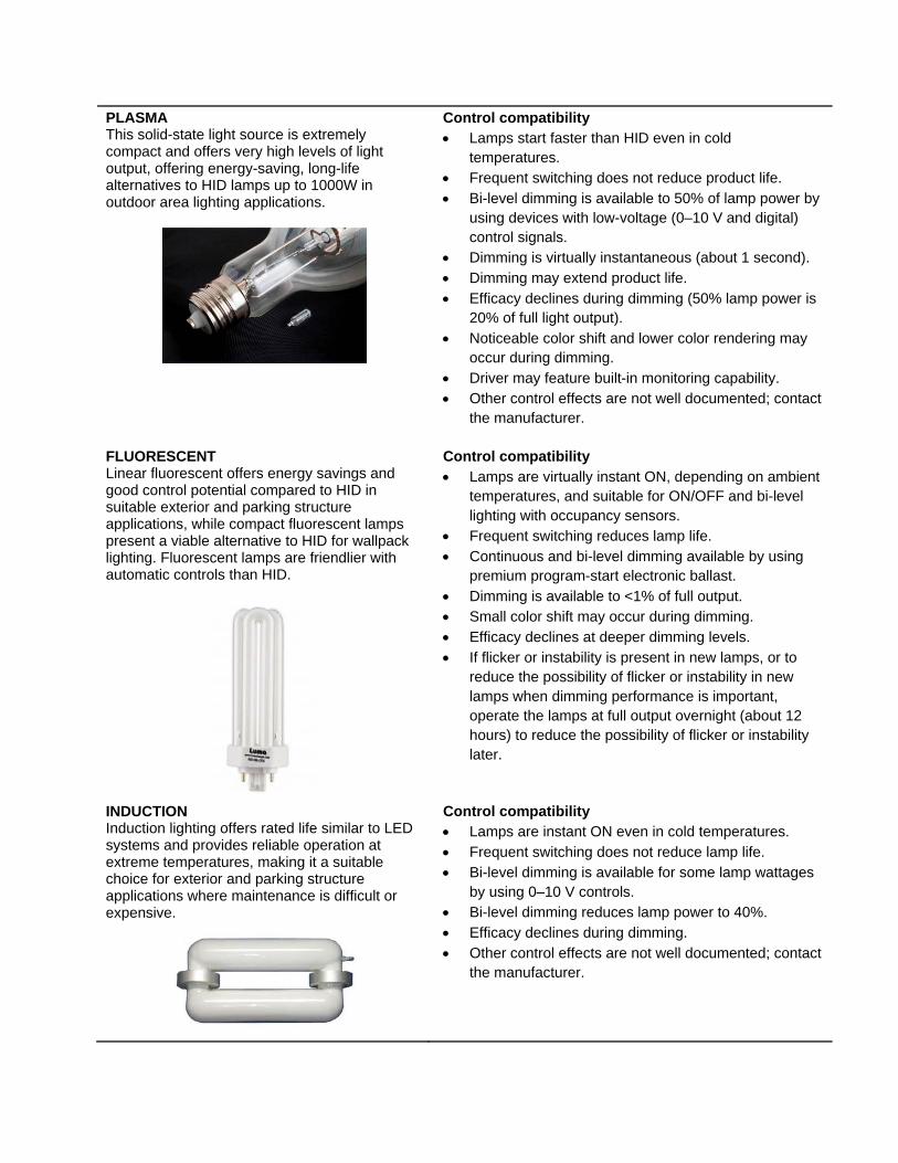
PLASMA This solid-state light source is extremely compact and offers very high levels of light output, offering energy-saving, long-life alternatives to HID lamps up to 1000W in outdoor area lighting applications.
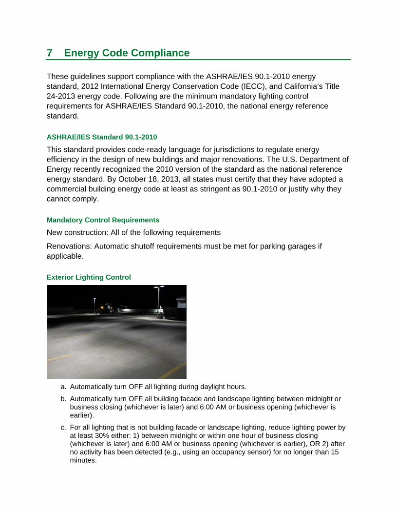
FLUORESCENT Linear fluorescent offers energy savings and good control potential compared to HID in suitable exterior and parking structure applications, while compact fluorescent lamps present a viable alternative to HID for wallpack lighting. Fluorescent lamps are friendlier with automatic controls than HID.
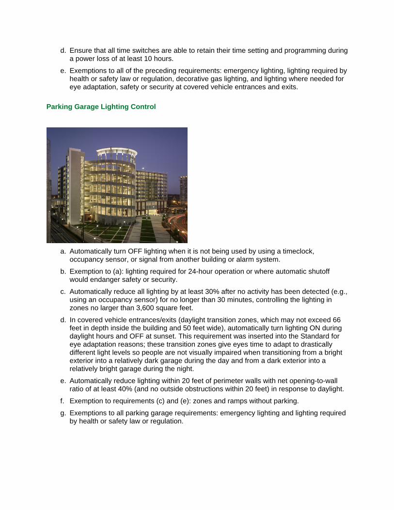
INDUCTION Induction lighting offers rated life similar to LED systems and provides reliable operation at extreme temperatures, making it a suitable choice for exterior and parking structure applications where maintenance is difficult or expensive.
Control compatibility Lamps start faster than HID even in cold
temperatures. Frequent switching does not reduce product life. Bi-level dimming is available to 50% of lamp power by
using devices with low-voltage (0–10 V and digital) control signals.
Dimming is virtually instantaneous (about 1 second). Dimming may extend product life. Efficacy declines during dimming (50% lamp power is
20% of full light output). Noticeable color shift and lower color rendering may
occur during dimming. Driver may feature built-in monitoring capability. Other control effects are not well documented; contact
the manufacturer.
Control compatibility Lamps are virtually instant ON, depending on ambient
temperatures, and suitable for ON/OFF and bi-level lighting with occupancy sensors.
Frequent switching reduces lamp life. Continuous and bi-level dimming available by using
premium program-start electronic ballast. Dimming is available to <1% of full output. Small color shift may occur during dimming. Efficacy declines at deeper dimming levels. If flicker or instability is present in new lamps, or to
reduce the possibility of flicker or instability in new lamps when dimming performance is important, operate the lamps at full output overnight (about 12 hours) to reduce the possibility of flicker or instability later.
Control compatibility Lamps are instant ON even in cold temperatures. Frequent switching does not reduce lamp life. Bi-level dimming is available for some lamp wattages
by using 0–10 V controls. Bi-level dimming reduces lamp power to 40%. Efficacy declines during dimming. Other control effects are not well documented; contact
the manufacturer.
7 Energy Code Compliance
These guidelines support compliance with the ASHRAE/IES 90.1-2010 energy standard, 2012 International Energy Conservation Code (IECC), and California’s Title 24-2013 energy code. Following are the minimum mandatory lighting control requirements for ASHRAE/IES Standard 90.1-2010, the national energy reference standard.
ASHRAE/IES Standard 90.1-2010
This standard provides code-ready language for jurisdictions to regulate energy efficiency in the design of new buildings and major renovations. The U.S. Department of Energy recently recognized the 2010 version of the standard as the national reference energy standard. By October 18, 2013, all states must certify that they have adopted a commercial building energy code at least as stringent as 90.1-2010 or justify why they cannot comply.
Mandatory Control Requirements
New construction: All of the following requirements
Renovations: Automatic shutoff requirements must be met for parking garages if applicable.
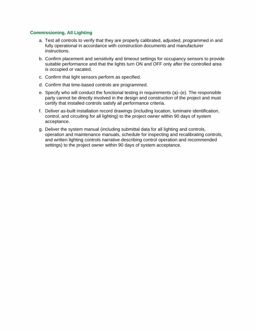
Exterior Lighting Control
a. Automatically turn OFF all lighting during daylight hours.
b. Automatically turn OFF all building facade and landscape lighting between midnight or business closing (whichever is later) and 6:00 AM or business opening (whichever is earlier).
c. For all lighting that is not building facade or landscape lighting, reduce lighting power by at least 30% either: 1) between midnight or within one hour of business closing (whichever is later) and 6:00 AM or business opening (whichever is earlier), OR 2) after no activity has been detected (e.g., using an occupancy sensor) for no longer than 15 minutes.
d. Ensure that all time switches are able to retain their time setting and programming during a power loss of at least 10 hours.
e. Exemptions to all of the preceding requirements: emergency lighting, lighting required by health or safety law or regulation, decorative gas lighting, and lighting where needed for eye adaptation, safety or security at covered vehicle entrances and exits.
Parking Garage Lighting Control
a. Automatically turn OFF lighting when it is not being used by using a timeclock, occupancy sensor, or signal from another building or alarm system.
b. Exemption to (a): lighting required for 24-hour operation or where automatic shutoff would endanger safety or security.
c. Automatically reduce all lighting by at least 30% after no activity has been detected (e.g., using an occupancy sensor) for no longer than 30 minutes, controlling the lighting in zones no larger than 3,600 square feet.
d. In covered vehicle entrances/exits (daylight transition zones, which may not exceed 66 feet in depth inside the building and 50 feet wide), automatically turn lighting ON during daylight hours and OFF at sunset. This requirement was inserted into the Standard for eye adaptation reasons; these transition zones give eyes time to adapt to drastically different light levels so people are not visually impaired when transitioning from a bright exterior into a relatively dark garage during the day and from a dark exterior into a relatively bright garage during the night.
e. Automatically reduce lighting within 20 feet of perimeter walls with net opening-to-wall ratio of at least 40% (and no outside obstructions within 20 feet) in response to daylight.
f. Exemption to requirements (c) and (e): zones and ramps without parking.
g. Exemptions to all parking garage requirements: emergency lighting and lighting required by health or safety law or regulation.
Commissioning, All Lighting
a. Test all controls to verify that they are properly calibrated, adjusted, programmed in and fully operational in accordance with construction documents and manufacturer instructions.
b. Confirm placement and sensitivity and timeout settings for occupancy sensors to provide suitable performance and that the lights turn ON and OFF only after the controlled area is occupied or vacated.
c. Confirm that light sensors perform as specified.
d. Confirm that time-based controls are programmed.
e. Specify who will conduct the functional testing in requirements (a)–(e). The responsible party cannot be directly involved in the design and construction of the project and must certify that installed controls satisfy all performance criteria.
f. Deliver as-built installation record drawings (including location, luminaire identification, control, and circuiting for all lighting) to the project owner within 90 days of system acceptance.
g. Deliver the system manual (including submittal data for all lighting and controls, operation and maintenance manuals, schedule for inspecting and recalibrating controls, and written lighting controls narrative describing control operation and recommended settings) to the project owner within 90 days of system acceptance.
8 Lighting Control Devices
Lighting control solutions include input devices (system timeclocks, light sensors, and occupancy sensors), lighting controllers (decision-making), power output controllers (controllable breakers, low-voltage relays, dimming ballasts/drivers and manual override switches)
PROGRAMMABLE SCHEDULING Enables timed load switching or dimming when lighting is no
longer needed, saving energy Scheduled automatic shutoff of curfew lighting Scheduled reduction of dusk-to-dawn lighting Intelligent digital dimming ballasts or LED drivers, controllable
breaker panels, low-voltage and intelligent low-voltage relay panels, or astronomical time switches as the point of control
Schedule programming at the device, low-voltage or intelligent low-voltage relay panel, or operator workstation (via software interface)
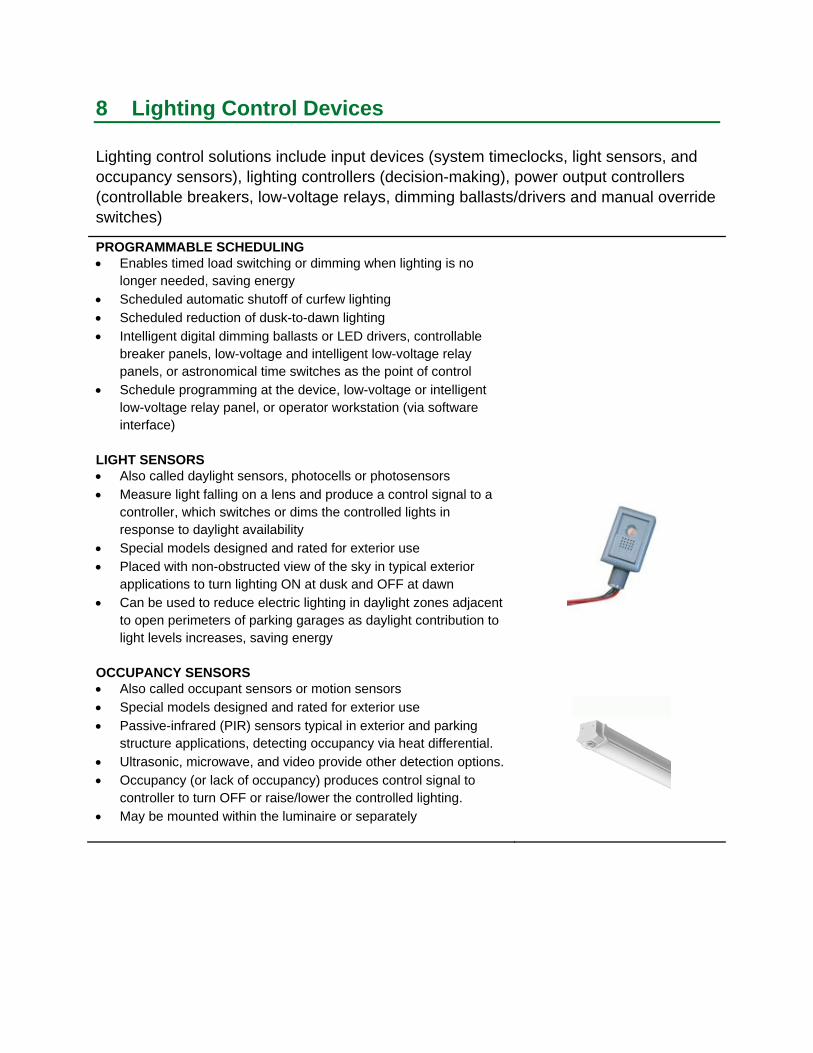
LIGHT SENSORS Also called daylight sensors, photocells or photosensors Measure light falling on a lens and produce a control signal to a
controller, which switches or dims the controlled lights in response to daylight availability
Special models designed and rated for exterior use Placed with non-obstructed view of the sky in typical exterior
applications to turn lighting ON at dusk and OFF at dawn Can be used to reduce electric lighting in daylight zones adjacent
to open perimeters of parking garages as daylight contribution to light levels increases, saving energy
OCCUPANCY SENSORS Also called occupant sensors or motion sensors Special models designed and rated for exterior use Passive-infrared (PIR) sensors typical in exterior and parking
structure applications, detecting occupancy via heat differential. Ultrasonic, microwave, and video provide other detection options. Occupancy (or lack of occupancy) produces control signal to
controller to turn OFF or raise/lower the controlled lighting. May be mounted within the luminaire or separately

DIMMING BALLASTS AND DRIVERS Specially designed devices used to control power to the load,
resulting in a reduction in lamp output and power Must be compatible with the lamp(s) being controlled Must be compatible with controls initiating the dimming May respond to controllers or feature onboard intelligence Some LED drivers feature onboard lumen maintenance dimming
feature, which provides constant light output over the life of the product with greater energy savings
Wired or wireless communication Digital and wireless connections enabling two-way
communication
SWITCHES Basic switches enabling facility operator override of automatic
control for special events and other purposes
9 Control Wiring
Control wiring provides a path for the communication of control signals between input devices and lighting controllers. While line-voltage (powerline carrier) communication is well suited to simple ON/OFF signals, it is relatively inflexible. Low-voltage communication is more commonly used for lighting controls, with digital wiring offering a higher degree of both elegance and flexibility. Radio-frequency (RF) communication is now becoming popular in both interior and exterior applications as a wireless option offering flexibility and scalability. Digital low-voltage and RF wireless both offer potential for two-way communication.
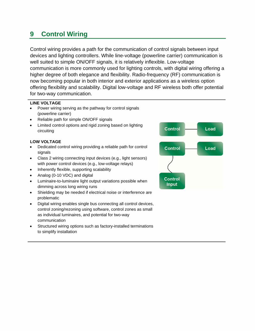
LINE VOLTAGE Power wiring serving as the pathway for control signals
(powerline carrier) Reliable path for simple ON/OFF signals Limited control options and rigid zoning based on lighting
circuiting
LOW VOLTAGE Dedicated control wiring providing a reliable path for control
signals Class 2 wiring connecting input devices (e.g., light sensors)
with power control devices (e.g., low-voltage relays) Inherently flexible, supporting scalability Analog (0-10 VDC) and digital Luminaire-to-luminaire light output variations possible when
dimming across long wiring runs Shielding may be needed if electrical noise or interference are
problematic Digital wiring enables single bus connecting all control devices,
control zoning/rezoning using software, control zones as small as individual luminaires, and potential for two-way communication
Structured wiring options such as factory-installed terminations to simplify installation
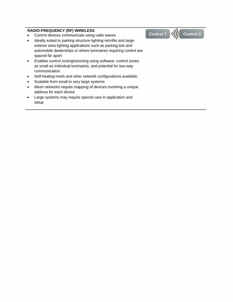
RADIO-FREQUENCY (RF) WIRELESS Control devices communicate using radio waves Ideally suited to parking structure lighting retrofits and large
exterior area lighting applications such as parking lots and automobile dealerships or where luminaires requiring control are spaced far apart
Enables control zoning/rezoning using software, control zones as small as individual luminaires, and potential for two-way communication
Self-healing mesh and other network configurations available. Scalable from small to very large systems Mesh networks require mapping of devices involving a unique
address for each device Large systems may require special care in application and
setup
10 Control Zoning
Control zoning is a critical component of an effective control solution. A control zone is a lighting load assigned to a single lighting controller or control strategy. In design, control zones are expressed on a control zone plan, which visually maps loads to control devices on lighting plans. In installation, control zoning is established using wiring or radio wireless connections, with flexibility increasing from line-voltage to low-voltage to digital-low-voltage and wireless. In more sophisticated control schemes, luminaires may participate in multiple control zones to implement different strategies. With digital low-voltage and wireless schemes, zoning and rezoning can be defined by software, multiple strategies may be economically layered on the same lighting load, and zoning can be implemented as precisely as single luminaires.
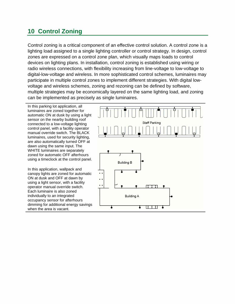
In this parking lot application, all luminaires are zoned together for automatic ON at dusk by using a light sensor on the nearby building roof connected to a low-voltage lighting control panel, with a facility operator manual override switch. The BLACK luminaires, used for security lighting, are also automatically turned OFF at dawn using the same input. The WHITE luminaires are separately zoned for automatic OFF afterhours using a timeclock at the control panel.
In this application, wallpack and canopy lights are zoned for automatic ON at dusk and OFF at dawn by using a light sensor, with a facility operator manual override switch. Each luminaire is also zoned individually to an integrated occupancy sensor for afterhours dimming for additional energy savings when the area is vacant.
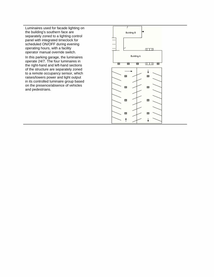
Luminaires used for facade lighting on the building’s southern face are separately zoned to a lighting control panel with integrated timeclock for scheduled ON/OFF during evening operating hours, with a facility operator manual override switch.
In this parking garage, the luminaires operate 24/7. The four luminaires in the right-hand and left-hand sections of the structure are separately zoned to a remote occupancy sensor, which raises/lowers power and light output in its controlled luminaire group based on the presence/absence of vehicles and pedestrians.
11 Commissioning
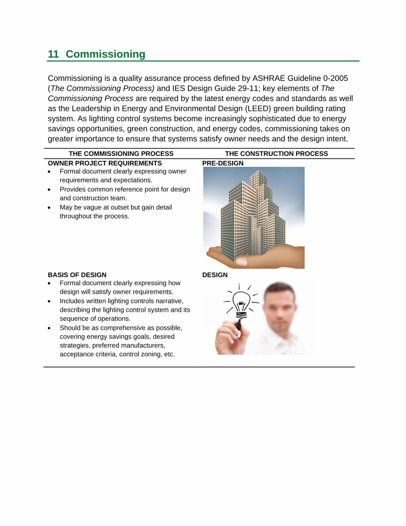
Commissioning is a quality assurance process defined by ASHRAE Guideline 0-2005 (The Commissioning Process) and IES Design Guide 29-11; key elements of The Commissioning Process are required by the latest energy codes and standards as well as the Leadership in Energy and Environmental Design (LEED) green building rating system. As lighting control systems become increasingly sophisticated due to energy savings opportunities, green construction, and energy codes, commissioning takes on greater importance to ensure that systems satisfy owner needs and the design intent.
THE COMMISSIONING PROCESS THE CONSTRUCTION PROCESS
OWNER PROJECT REQUIREMENTS PRE-DESIGN Formal document clearly expressing owner
requirements and expectations. Provides common reference point for design
and construction team. May be vague at outset but gain detail
throughout the process.
BASIS OF DESIGN DESIGN Formal document clearly expressing how
design will satisfy owner requirements. Includes written lighting controls narrative,
describing the lighting control system and its sequence of operations.
Should be as comprehensive as possible, covering energy savings goals, desired strategies, preferred manufacturers, acceptance criteria, control zoning, etc.
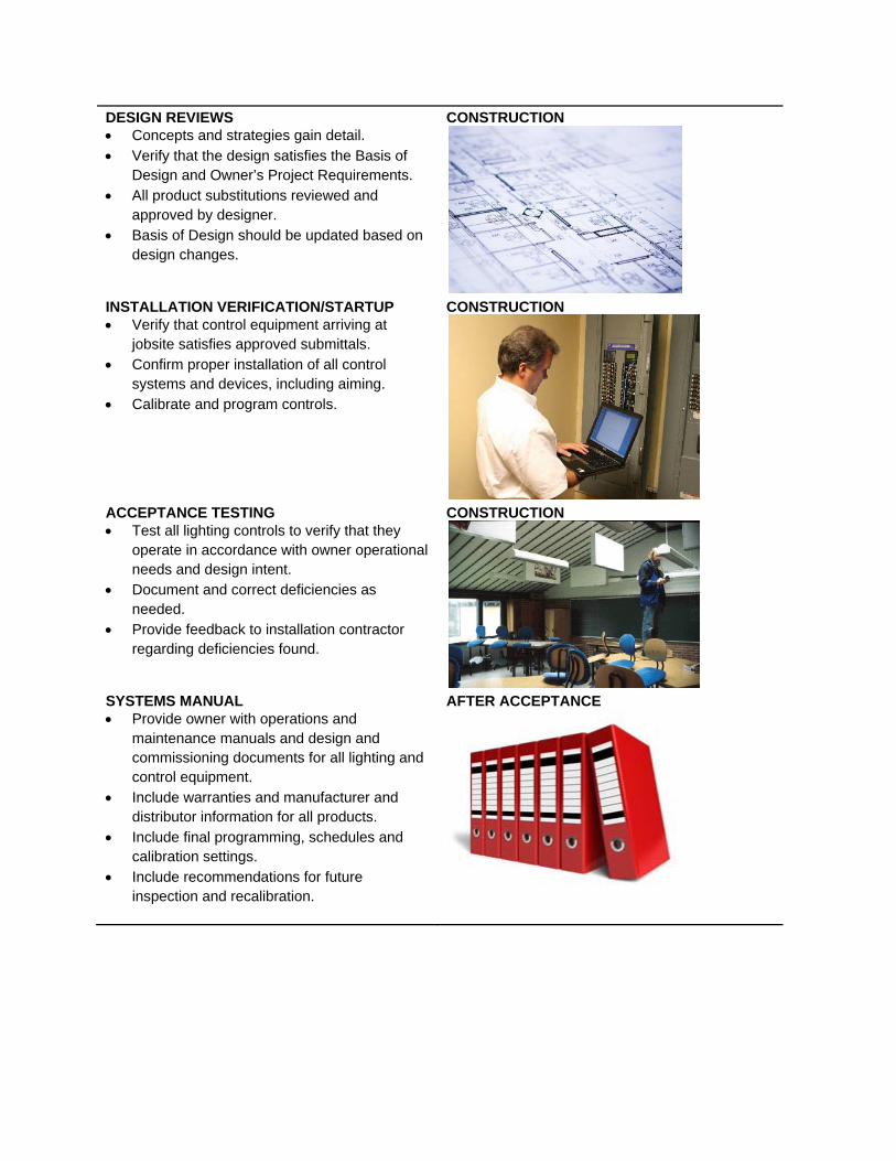
DESIGN REVIEWS Concepts and strategies gain detail. Verify that the design satisfies the Basis of
Design and Owner’s Project Requirements. All product substitutions reviewed and
approved by designer. Basis of Design should be updated based on
design changes.
INSTALLATION VERIFICATION/STARTUP Verify that control equipment arriving at
jobsite satisfies approved submittals. Confirm proper installation of all control
systems and devices, including aiming. Calibrate and program controls.
ACCEPTANCE TESTING Test all lighting controls to verify that they
operate in accordance with owner operational needs and design intent.
Document and correct deficiencies as needed.
Provide feedback to installation contractor regarding deficiencies found.
SYSTEMS MANUAL Provide owner with operations and
maintenance manuals and design and commissioning documents for all lighting and control equipment.
Include warranties and manufacturer and distributor information for all products.
Include final programming, schedules and calibration settings.
Include recommendations for future inspection and recalibration.
CONSTRUCTION
CONSTRUCTION
AFTER ACCEPTANCE
CONSTRUCTION

USER TRAINING AFTER ACCEPTANCE Train facility personnel to properly operate
and maintain lighting and control systems.
MAINTENANCE AND UPKEEP POST-OCCUPANCY Schedule a post-occupancy
meeting10 months after acceptance to review performance and address issues.
Document any new changes to system or site operation.
Incorporate inspection and recalibration into ongoing maintenance regime.
12 Light Reduction Control using Occupancy Sensors
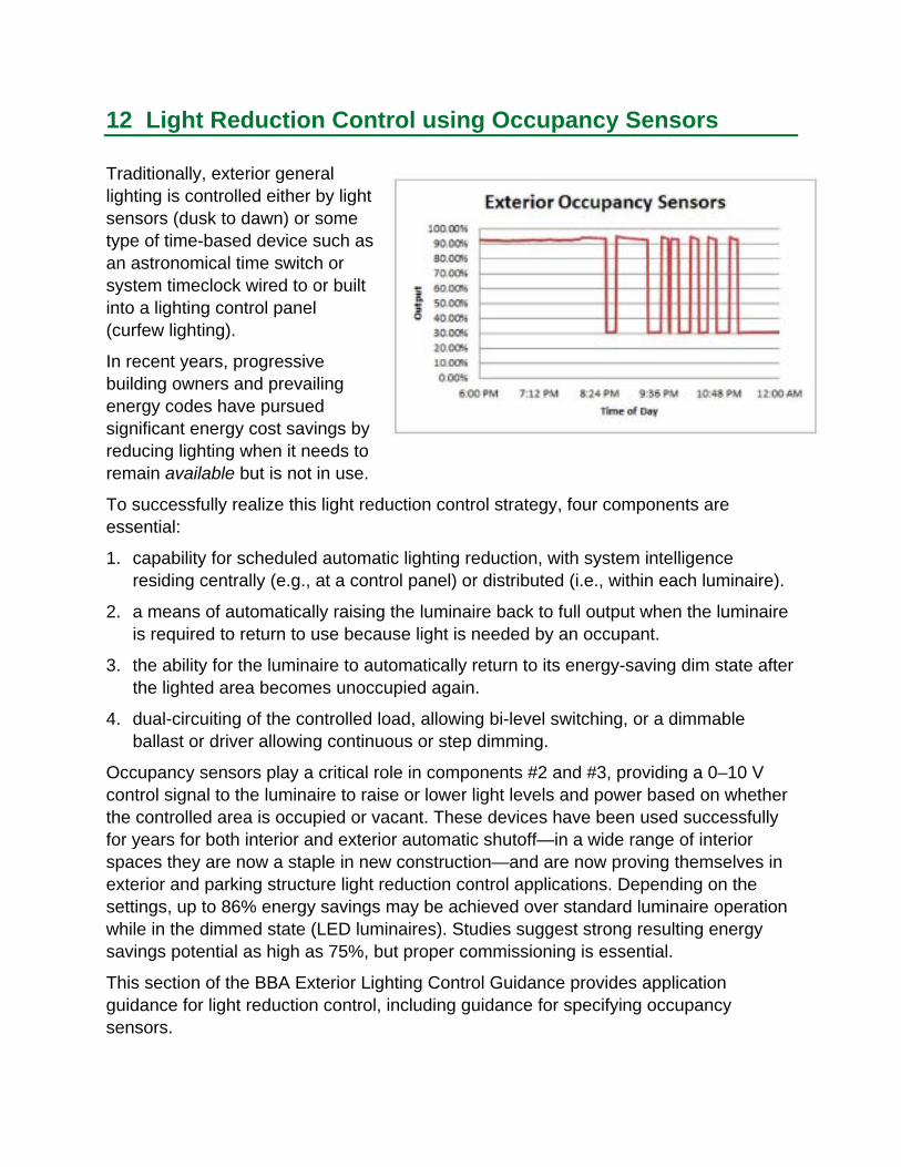
Traditionally, exterior general lighting is controlled either by light sensors (dusk to dawn) or some type of time-based device such as an astronomical time switch or system timeclock wired to or built into a lighting control panel (curfew lighting).
In recent years, progressive building owners and prevailing energy codes have pursued significant energy cost savings by reducing lighting when it needs to remain available but is not in use.
To successfully realize this light reduction control strategy, four components are essential:
1. capability for scheduled automatic lighting reduction, with system intelligence residing centrally (e.g., at a control panel) or distributed (i.e., within each luminaire).
2. a means of automatically raising the luminaire back to full output when the luminaire is required to return to use because light is needed by an occupant.
3. the ability for the luminaire to automatically return to its energy-saving dim state after the lighted area becomes unoccupied again.
4. dual-circuiting of the controlled load, allowing bi-level switching, or a dimmable ballast or driver allowing continuous or step dimming.
Occupancy sensors play a critical role in components #2 and #3, providing a 0–10 V control signal to the luminaire to raise or lower light levels and power based on whether the controlled area is occupied or vacant. These devices have been used successfully for years for both interior and exterior automatic shutoff—in a wide range of interior spaces they are now a staple in new construction—and are now proving themselves in exterior and parking structure light reduction control applications. Depending on the settings, up to 86% energy savings may be achieved over standard luminaire operation while in the dimmed state (LED luminaires). Studies suggest strong resulting energy savings potential as high as 75%, but proper commissioning is essential.
This section of the BBA Exterior Lighting Control Guidance provides application guidance for light reduction control, including guidance for specifying occupancy sensors.

CLTC Research
The California Lighting Technology Center (CLTC) has actively worked with the manufacturing community to develop and test bi-level exterior lighting solutions.
Bi-level street and parking area luminaires
Alternative to HID LED and induction luminaires with
integral occupancy sensor and bi-level control
About 30% energy savings for a controlled LED area luminaire and 75% energy savings for a controlled cobrahead induction area luminaire
Instant to 6-year payback for new construction (compared to traditional high-pressure sodium) and 5- to 15-year payback in retrofits
Bi-level cobrahead induction luminaire at California Polytechnic State University
Bi-level HID wall packs
Alternative to HID without bi-level control HID luminaires with integral occupancy
sensor and bi-level control About 40% energy savings for controlled
luminaires
Bi-level smart LED parking garage luminaire
Alternative to HID Up to 40% energy savings using LED
technology Additional 30% energy savings using
occupancy-sensor-based bi-level control
Bi-level LED parking garage luminaire at Sacramento State University
Bi-level HID wall pack at Chico State University
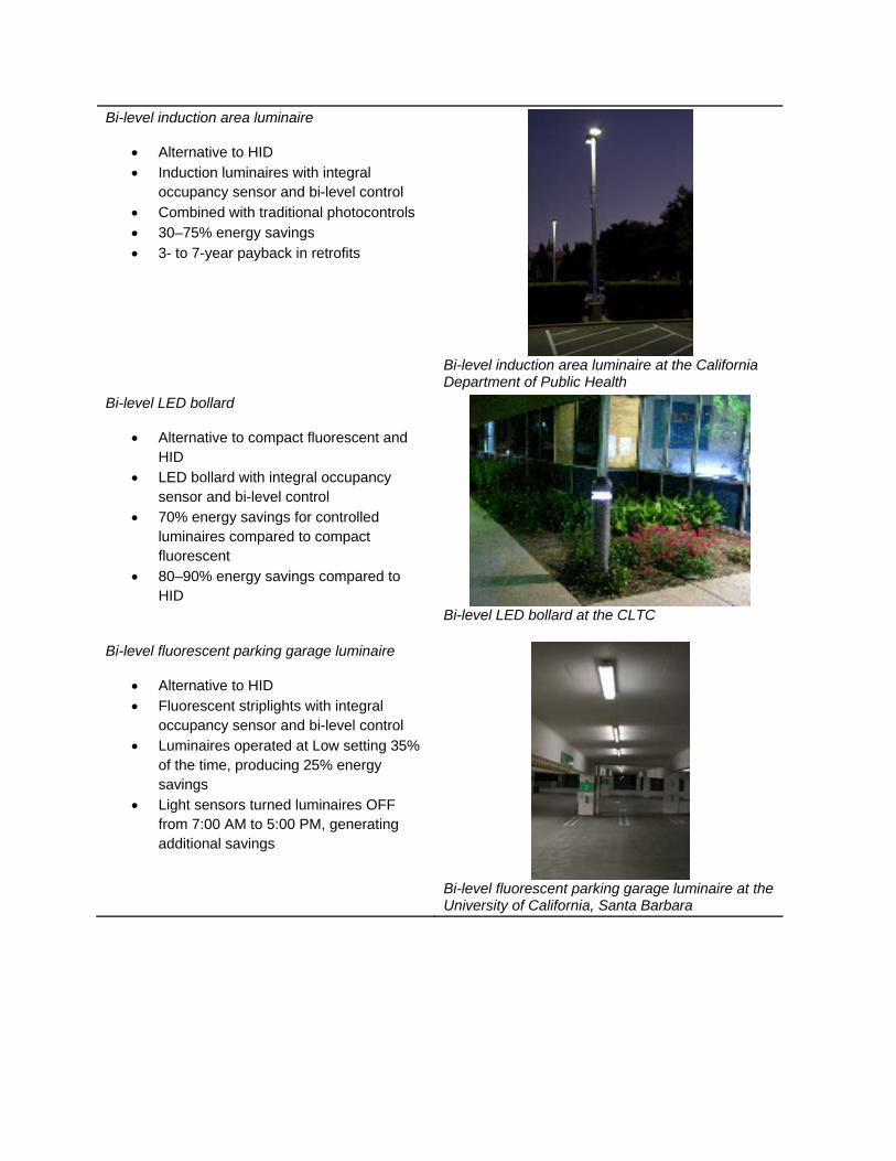
Bi-level induction area luminaire
Alternative to HID Induction luminaires with integral
occupancy sensor and bi-level control Combined with traditional photocontrols 30–75% energy savings 3- to 7-year payback in retrofits
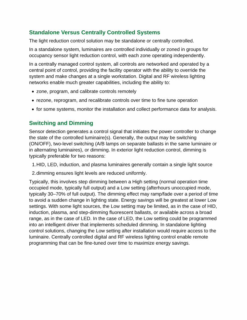
Bi-level LED bollard
Alternative to compact fluorescent and HID
LED bollard with integral occupancy sensor and bi-level control
70% energy savings for controlled luminaires compared to compact fluorescent
80–90% energy savings compared to HID
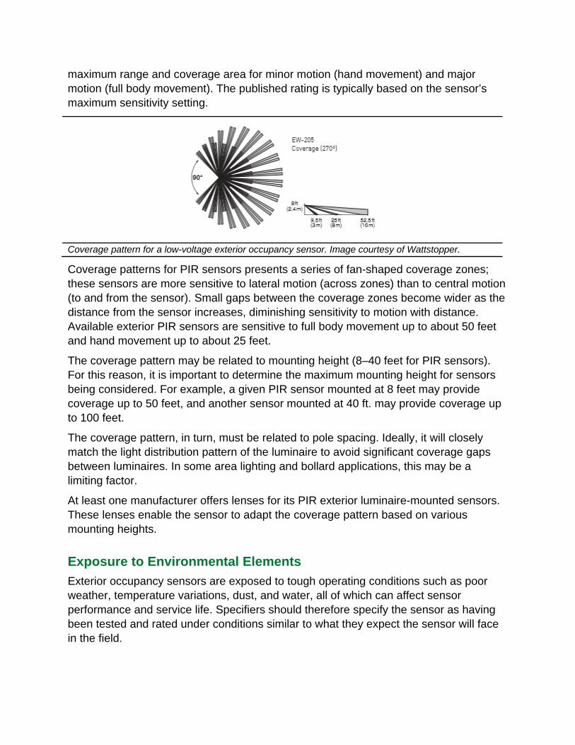
Bi-level fluorescent parking garage luminaire
Alternative to HID Fluorescent striplights with integral
occupancy sensor and bi-level control Luminaires operated at Low setting 35%
of the time, producing 25% energy savings
Light sensors turned luminaires OFF from 7:00 AM to 5:00 PM, generating additional savings
Bi-level induction area luminaire at the California Department of Public Health
Bi-level LED bollard at the CLTC
Bi-level fluorescent parking garage luminaire at the University of California, Santa Barbara

Bi-level LED post-top luminaire
Alternative to HID LED post-top luminaire with integral
occupancy sensor and bi-level control About 69% energy savings based on
30% occupancy rate
Bi-level LED post-top luminaire at the Los Angeles Trade Technical College
U.S. Department of Energy Research (GATEWAY demonstration projects)
U.S. Department of Labor
Bi-level LED luminaires replaced high-pressure sodium luminaires in parking garage
52% energy savings from LED technology
Energy savings increased to 88% with occupancy sensors and bi-level control
Occupancy sensors reduced power to 10% after time delay of 2.5 minutes
Occasional false tripping of lights by sensors but no negative overall impact
No complaints from garage users Simple payback of 4.9 years for new
construction and 6.5 years for retrofit, primarily due to higher cost of LEDs
Four parking lot and structure projects
DOE collected data on four early installations of bi-level LED products
Energy savings ranged 19-76% with Low settings of 10–33% and time delay of 2–5 minutes in three projects
One project failed, likely due to wind Lessons learned included deficiencies in
products to withstand sustained environmental exposure, inadequate design, lack of dedicated commissioning, and operation of multiple controls overlapping luminaires

Detection Methods
Occupancy sensors detect occupancy using one of several methods, including passive-infrared (PIR), ultrasonic, dual technology (ultrasonic/PIR and acoustic/PIR), microwave, and camera. In exterior and parking structure applications, PIR is generally the favored approach because of its simple operation and relatively low power requirement. Although more sensitive than PIR and able to “see” around objects, ultrasonic is typically not used in these applications because often the required area of coverage is larger, features high mounting heights, and lacks walls enclosures to reflect a sonic signal.
PIR Sensors
PIR sensors identify movement by detecting differences in infrared radiation using a pyroelectric chip. Most commonly, a Fresnel lens (or set of lenses) directs energy toward the sensor from a wide field of view. The plastic lens both protects and provides optics for the sensor but is transparent to the infrared radiation. The segments of the Fresnel lens create distinct radial zones of detection, resulting in a discontinuous field of view. Motion is detected when an object such as a pedestrian or vehicle emitting a different level of heat radiation enters the background within a given zone. The lens focuses the heat from the object on the pyroelectric chip, creating an electric signal that is manipulated and transferred via control circuitry to control the output level of the luminaire.
Microwave
Microwave-based occupancy sensors emit a low-power microwave into the coverage area and detect changes in the reflection pattern caused by motion.
Camera (video)
Manufacturers are exploring camera-based occupancy sensors. These devices capture multiple images of the coverage area per second, and detect body types using complex algorithms. Potential advantages include reduction of false positives from objects such as branches or other elements in the field of view. Further, these sensors have the ability to eliminate portions of the camera’s view from the coverage area, enabling refined coverage patterns such as squares.
Standalone Versus Centrally Controlled Systems
The light reduction control solution may be standalone or centrally controlled.
In a standalone system, luminaires are controlled individually or zoned in groups for occupancy sensor light reduction control, with each zone operating independently.
In a centrally managed control system, all controls are networked and operated by a central point of control, providing the facility operator with the ability to override the system and make changes at a single workstation. Digital and RF wireless lighting networks enable much greater capabilities, including the ability to:
zone, program, and calibrate controls remotely
rezone, reprogram, and recalibrate controls over time to fine tune operation
for some systems, monitor the installation and collect performance data for analysis.
Switching and Dimming
Sensor detection generates a control signal that initiates the power controller to change the state of the controlled luminaire(s). Generally, the output may be switching (ON/OFF), two-level switching (A/B lamps on separate ballasts in the same luminaire or in alternating luminaires), or dimming. In exterior light reduction control, dimming is typically preferable for two reasons:
1.HID, LED, induction, and plasma luminaires generally contain a single light source
2.dimming ensures light levels are reduced uniformly.
Typically, this involves step dimming between a High setting (normal operation time occupied mode, typically full output) and a Low setting (afterhours unoccupied mode, typically 30–70% of full output). The dimming effect may ramp/fade over a period of time to avoid a sudden change in lighting state. Energy savings will be greatest at lower Low settings. With some light sources, the Low setting may be limited, as in the case of HID, induction, plasma, and step-dimming fluorescent ballasts, or available across a broad range, as in the case of LED. In the case of LED, the Low setting could be programmed into an intelligent driver that implements scheduled dimming. In standalone lighting control solutions, changing the Low setting after installation would require access to the luminaire. Centrally controlled digital and RF wireless lighting control enable remote programming that can be fine-tuned over time to maximize energy savings.

The dimming effect may ramp/fade over a period of time to avoid a sudden change in lighting state. Image courtesy of Sensor Switch.
The image on the left is an occupied space with LED luminaire in state (10% full power). The image on the right is an occupied parking space with LED luminaire in high state (100% full power).
Mounting
Occupancy sensors may be installed remotely from or within outdoor area, wallpack, bollard and parking structure luminaires.
Remote mounting is suitable for control zoning of multiple luminaires or where optimal sensor placement calls for it. For example, in a parking structure, multiple luminaires along an entire driving lane can be controlled by a single sensor, which supports visual needs while reducing cost. Remote sensors can also be strategically placed to address concerns about areas of inadequate sensor coverage (dead zones). However, remote sensors require careful design. If remote mounting is needed but poses wiring challenges, consider RF wireless devices.

Luminaire mounting is well suited to individual luminaire control. The sensor may be attached to the luminaire (wired in the field) or specified as an integral component, which may simplify installation. Some sensors integrate a light sensor and an occupancy sensor into a single unit. Based on an illumination setpoint, the light sensor holds the lights OFF or at a low level
when sufficient daylight is available.
Coverage
Occupancy sensors cover an area that is determined by its field of view and range, resulting in a coverage pattern and area.
Field of View
The sensor’s field of view is typically 360 degrees (top view), which is limited by the pole to 270 degrees if the luminaire is pole-mounted.
PIR sensors require a clear line of sight for detection, which provides the ability to restrict the field of view if required by the application, but also poses a challenge. In exterior and parking structure applications, structural, utility, natural elements, and even large vehicles can block the line of sight on a permanent (predictable) or transitory (unpredictable) basis, requiring careful design.
In this parking garage, obstructions challenge the line of sight for PIR occupancy sensors. Image courtesy of the U.S. Department of Energy.
Coverage Pattern
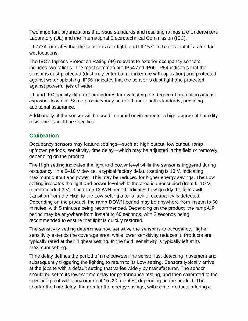
The coverage pattern for an occupancy sensor indicates its range (feet) and coverage area (square feet). Many different coverage sizes and shapes for available, commonly fan-shaped (side view) and circular (top view). The coverage pattern may indicate the
maximum range and coverage area for minor motion (hand movement) and major motion (full body movement). The published rating is typically based on the sensor’s maximum sensitivity setting.
Coverage pattern for a low-voltage exterior occupancy sensor. Image courtesy of Wattstopper.
Coverage patterns for PIR sensors presents a series of fan-shaped coverage zones; these sensors are more sensitive to lateral motion (across zones) than to central motion (to and from the sensor). Small gaps between the coverage zones become wider as the distance from the sensor increases, diminishing sensitivity to motion with distance. Available exterior PIR sensors are sensitive to full body movement up to about 50 feet and hand movement up to about 25 feet.
The coverage pattern may be related to mounting height (8–40 feet for PIR sensors). For this reason, it is important to determine the maximum mounting height for sensors being considered. For example, a given PIR sensor mounted at 8 feet may provide coverage up to 50 feet, and another sensor mounted at 40 ft. may provide coverage up to 100 feet.
The coverage pattern, in turn, must be related to pole spacing. Ideally, it will closely match the light distribution pattern of the luminaire to avoid significant coverage gaps between luminaires. In some area lighting and bollard applications, this may be a limiting factor.
At least one manufacturer offers lenses for its PIR exterior luminaire-mounted sensors. These lenses enable the sensor to adapt the coverage pattern based on various mounting heights.
Exposure to Environmental Elements
Exterior occupancy sensors are exposed to tough operating conditions such as poor weather, temperature variations, dust, and water, all of which can affect sensor performance and service life. Specifiers should therefore specify the sensor as having been tested and rated under conditions similar to what they expect the sensor will face in the field.
Two important organizations that issue standards and resulting ratings are Underwriters Laboratory (UL) and the International Electrotechnical Commission (IEC).
UL773A indicates that the sensor is rain-tight, and UL1571 indicates that it is rated for wet locations.
The IEC’s Ingress Protection Rating (IP) relevant to exterior occupancy sensors includes two ratings. The most common are IP54 and IP66. IP54 indicates that the sensor is dust-protected (dust may enter but not interfere with operation) and protected against water splashing. IP66 indicates that the sensor is dust-tight and protected against powerful jets of water.
UL and IEC specify different procedures for evaluating the degree of protection against exposure to water. Some products may be rated under both standards, providing additional assurance.
Additionally, if the sensor will be used in humid environments, a high degree of humidity resistance should be specified.
Calibration
Occupancy sensors may feature settings—such as high output, low output, ramp up/down periods, sensitivity, time delay—which may be adjusted in the field or remotely, depending on the product.
The High setting indicates the light and power level while the sensor is triggered during occupancy. In a 0–10 V device, a typical factory default setting is 10 V, indicating maximum output and power. This may be reduced for higher energy savings. The Low setting indicates the light and power level while the area is unoccupied (from 0–10 V, recommended 3 V). The ramp-DOWN period indicates how quickly the lights will transition from the High to the Low setting after a lack of occupancy is detected. Depending on the product, the ramp-DOWN period may be anywhere from instant to 60 minutes, with 5 minutes being recommended. Depending on the product, the ramp-UP period may be anywhere from instant to 60 seconds, with 3 seconds being recommended to ensure that light is quickly restored.
The sensitivity setting determines how sensitive the sensor is to occupancy. Higher sensitivity extends the coverage area, while lower sensitivity reduces it. Products are typically rated at their highest setting. In the field, sensitivity is typically left at its maximum setting.
Time delay defines the period of time between the sensor last detecting movement and subsequently triggering the lighting to return to its Low setting. Sensors typically arrive at the jobsite with a default setting that varies widely by manufacturer. The sensor should be set to its lowest time delay for performance testing, and then calibrated to the specified point with a maximum of 15–20 minutes, depending on the product. The shorter the time delay, the greater the energy savings, with some products offering a
time delay setting as short as 30 seconds. For maximum savings, a time delay of <5 minutes is recommended.
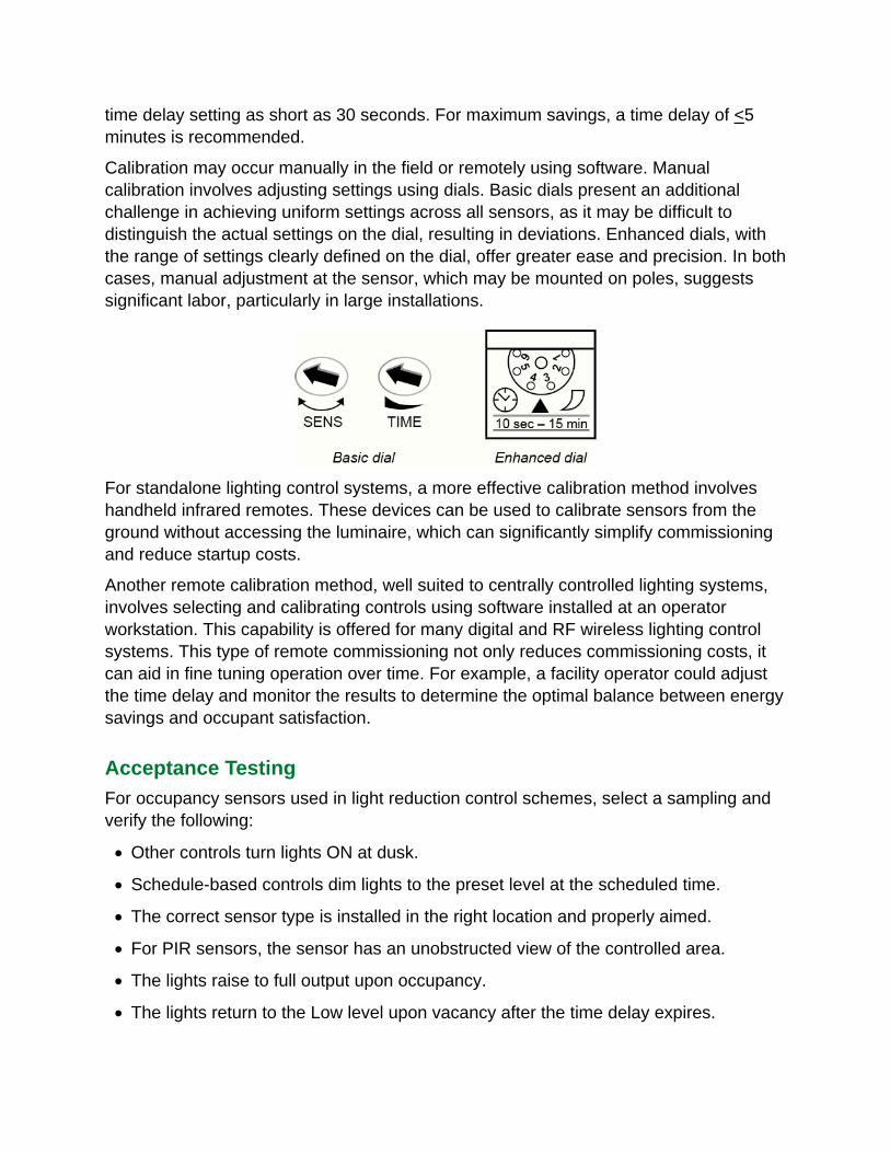
Calibration may occur manually in the field or remotely using software. Manual calibration involves adjusting settings using dials. Basic dials present an additional challenge in achieving uniform settings across all sensors, as it may be difficult to distinguish the actual settings on the dial, resulting in deviations. Enhanced dials, with the range of settings clearly defined on the dial, offer greater ease and precision. In both cases, manual adjustment at the sensor, which may be mounted on poles, suggests significant labor, particularly in large installations.
For standalone lighting control systems, a more effective calibration method involves handheld infrared remotes. These devices can be used to calibrate sensors from the ground without accessing the luminaire, which can significantly simplify commissioning and reduce startup costs.
Another remote calibration method, well suited to centrally controlled lighting systems, involves selecting and calibrating controls using software installed at an operator workstation. This capability is offered for many digital and RF wireless lighting control systems. This type of remote commissioning not only reduces commissioning costs, it can aid in fine tuning operation over time. For example, a facility operator could adjust the time delay and monitor the results to determine the optimal balance between energy savings and occupant satisfaction.
Acceptance Testing
For occupancy sensors used in light reduction control schemes, select a sampling and verify the following:
Other controls turn lights ON at dusk.
Schedule-based controls dim lights to the preset level at the scheduled time.
The correct sensor type is installed in the right location and properly aimed.
For PIR sensors, the sensor has an unobstructed view of the controlled area.
The lights raise to full output upon occupancy.
The lights return to the Low level upon vacancy after the time delay expires.
The integral light sensor holds the lights OFF or at a low level if sufficient daylight is available based on a selected setpoint (some products).
General Specifications
A detailed performance specification for adaptive exterior lighting control systems has been developed by the U.S. Department of Energy-sponsored Municipal Street Lighting Consortium. The specification is comprehensive and oriented toward LED street and roadway lighting systems but may be adapted in whole or part for other applications such as area lighting. This specification may be downloaded at http://www1.eere.energy.gov/buildings/ssl/control-specification.html.
A detailed performance specification for energy-efficient exterior wallpack luminaires has been developed by the Better Buildings Alliance. The specification includes a section for bi-level lighting control and may be downloaded at http://www4.eere.energy.gov/alliance/activities/technology-solutions-teams/lighting-electrical/wallpack-lighting.
Occupancy Sensor Specification Parameters
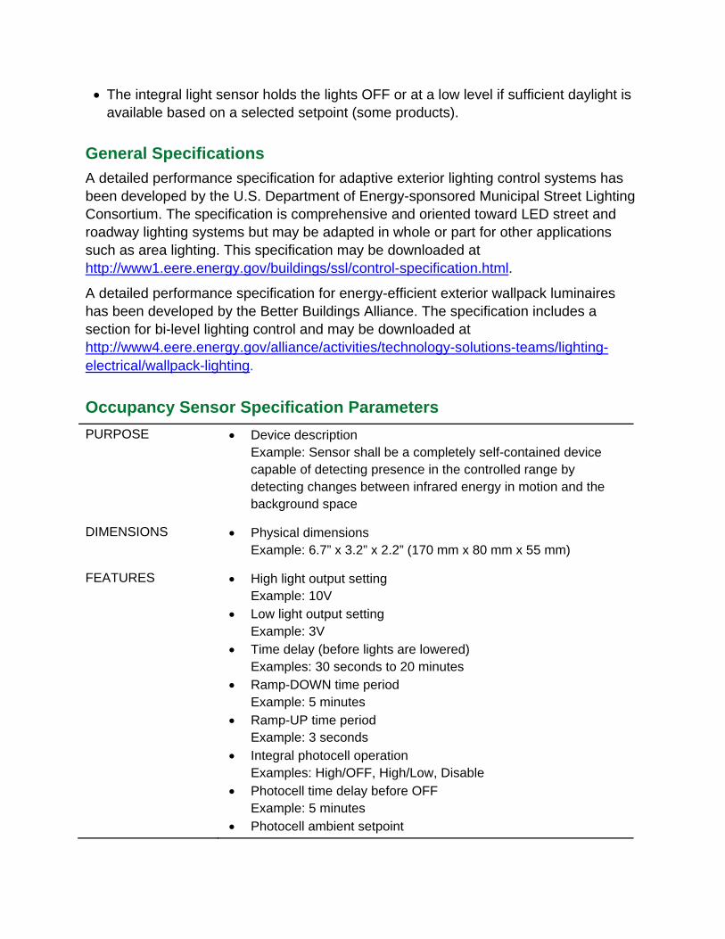
PURPOSE Device description Example: Sensor shall be a completely self-contained device capable of detecting presence in the controlled range by detecting changes between infrared energy in motion and the background space
DIMENSIONS Physical dimensions Example: 6.7” x 3.2” x 2.2” (170 mm x 80 mm x 55 mm)
FEATURES High light output setting Example: 10V
Low light output setting Example: 3V
Time delay (before lights are lowered) Examples: 30 seconds to 20 minutes
Ramp-DOWN time period Example: 5 minutes
Ramp-UP time period Example: 3 seconds
Integral photocell operation Examples: High/OFF, High/Low, Disable
Photocell time delay before OFF Example: 5 minutes
Photocell ambient setpoint

Example: 200 footcandles Photocell time delay before ON
Example: 45 seconds
COVERAGE AREA Range and field of view Example: Sensor on pole-mounted luminaire shall provide adequate coverage up to 50 feet with a field of view of 270 degrees at a mounting height of 8 feet
LOAD RATING Compatibility Example: Sensor shall be compatible with 0-10VDC dimmable ballasts and LED drivers
Type of lighting load Example: 0-10VDC LED driver
Load rating Example: 800W @ 120VAC, 1000W @208 VAC, 1200W @ 240/277VAC, 1500W @ 347VAC, 2160W @ 480VAC
Minimum load Example: None
Frequency Example: 50/60 Hz
COLOR Color of the sensor if applicable Example: White, black
VOLTAGE Device voltage Example: 24VDC
MOUNTING Mounting height Example: Sensor shall be capable of providing specified coverage at mounting height of 15 feet
Mounting method Example: 1/2” knockout (7/8” hole) Example: Sensor shall be capable of luminaire or pole mounting
EXPOSURE Resistance to elements Example: Sensor shall be gasketed for outdoor operation
Ratings for exposure to the elements Examples: UL773A (rain-tight), UL 1571 (wet locations), IP66 (dust-tight and protected against strong jets of water)
Resistance to humidity Example: 20-90% non-condensing
OPERATING Operating temperature TEMPERATURE Example: -40 to 160 degrees F (-40 to 71 degrees C)
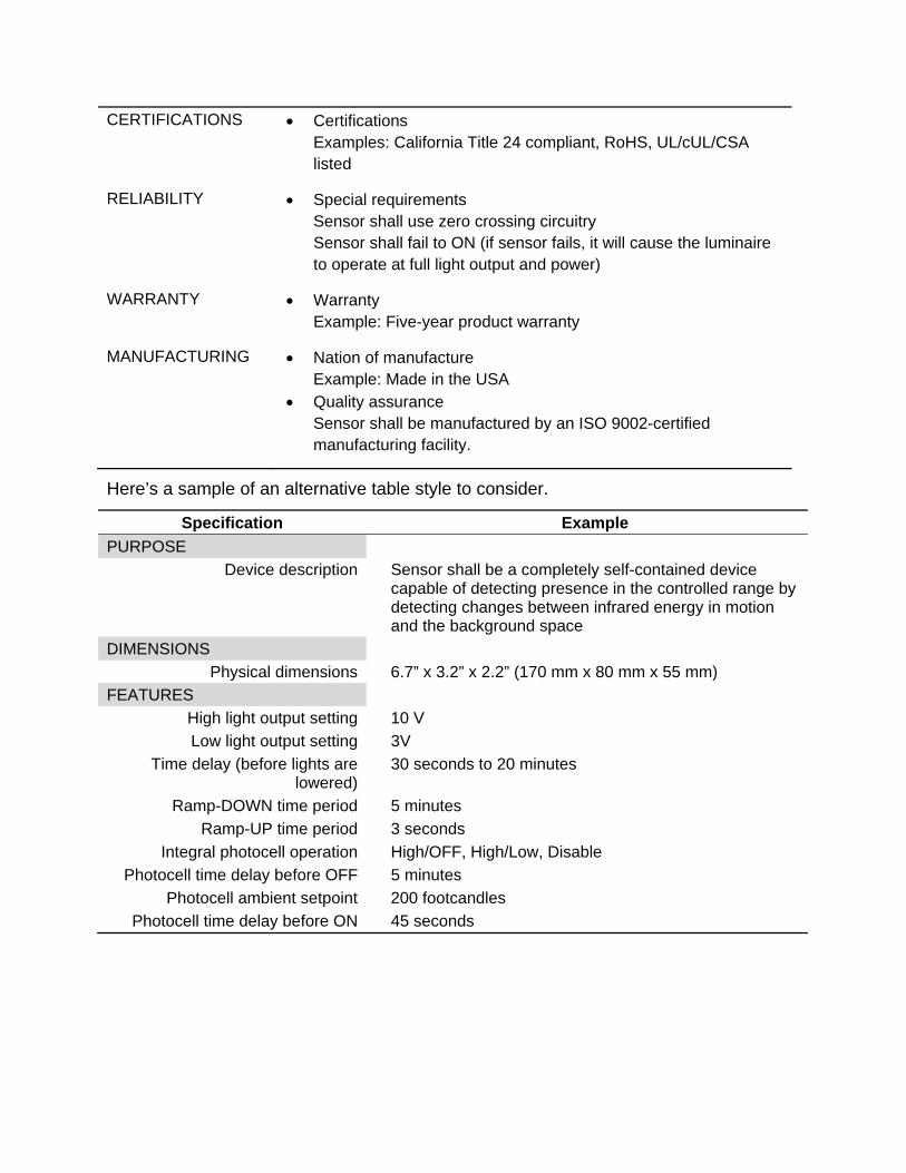
CERTIFICATIONS Certifications Examples: California Title 24 compliant, RoHS, UL/cUL/CSA listed
RELIABILITY Special requirements Sensor shall use zero crossing circuitry Sensor shall fail to ON (if sensor fails, it will cause the luminaire to operate at full light output and power)
WARRANTY Warranty Example: Five-year product warranty
MANUFACTURING Nation of manufacture Example: Made in the USA
Quality assurance Sensor shall be manufactured by an ISO 9002-certified manufacturing facility.
Here’s a sample of an alternative table style to consider.
Specification Example
PURPOSE
Device description Sensor shall be a completely self-contained device capable of detecting presence in the controlled range by detecting changes between infrared energy in motion and the background space
DIMENSIONS
Physical dimensions 6.7” x 3.2” x 2.2” (170 mm x 80 mm x 55 mm)
FEATURES
High light output setting 10 V
Low light output setting 3V
Time delay (before lights are 30 seconds to 20 minutes lowered)
Ramp-DOWN time period 5 minutes
Ramp-UP time period 3 seconds
Integral photocell operation High/OFF, High/Low, Disable
Photocell time delay before OFF 5 minutes
Photocell ambient setpoint 200 footcandles
Photocell time delay before ON 45 seconds