Embed Size (px)
Citation preview

363
extensIBLe ConVeYoR sYsteMs FoR LonG tunneLs WItHout InteRMeDIAte ACCess
Dean Workman The Robbins Company
ABstRACtLong extensible conveyor systems are an important option for efficient tunnel
excavation where intermediate access is impractical. The conveyor system designed for the Pula Subbaiah Veligonda Tunnel #2 in Andhra Pradesh, India will eventually extend to 19.35km. The Ø10.0m water diversion tunnel will be excavated under India’s largest tiger sanctuary using a Robbins Double Shield TBM. Once extended, the con-veyor will be one of the longest single-flight systems ever installed in India, and is expected to offer increased system availability over comparable systems using muck cars. This paper will examine the engineering challenges of long-flight extensible con-veyor systems in the areas of belt selection, component design, and equipment loca-tion in confined assembly and launch areas.
oVeRVIeWAs extensible conveyors continue to gain acceptance as the standard muck removal
system for tunnel boring machines, the length of the muck conveyor required has also continued to increase based on the project specifications. In some projects, intermedi-ate access to the tunnel, either by a vertical shaft or a sloping adit, has allowed the muck to be removed from the tunnel at a point other than the starting portal. Utilizing these designed-in features results in a shorter and therefore less expensive conveyor system, with the trade-off being an increase in labor costs due to the time necessary to disassemble and then re-install the system after the TBM has advanced beyond the access. However, there are instances where intermediate access to the tunnel by a shaft or an adit would either be impractical or cost-prohibitive. Contributing factors preventing intermediate access include (a) environmentally sensitive areas, such as a national park or nature preserve; (b) geographic locations, such as a dense metro-politan area or a large body of water; or (c) geological limitations, such as the depth of the tunnel or the stratigraphy of the overlying ground. In these situations an extensible conveyor can still be the most economic muck removal method, despite the increase in its ultimate length and the resulting conveyor system requirements. This paper will highlight the engineering challenges and solutions faced in one such example.
tunneL DesCRIPtIonThe Pula Subbaiah Veligonda Tunnel #2 in Andhra Pradesh, India will connect
the existing Srisailam Reservoir on the Krishna River with eighteen irrigation projects in the districts of Prakasam, Nellore, and Kadapa, and is in the same general location as tunnel projects AMR #1 and AMR #2, which will also connect with the reservoir. However, this Ø10.0M water diversion tunnel will be bored under the Nallamala Hills and will eventually reach a length of 19.2 kilometers. The Nallamala is home to the Nagarjunasagar Reserve, India’s largest tiger sanctuary, making intermediate access to the tunnel from within the Reserve environmentally complicated and potentially
InnoVAtIonextensIBLe ConVeYoR sYsteMs

364 InnoVAtIon
dangerous. This constraint required that the Veligonda tunnel be bored in one continu-ous operation, and with a minimum of perceivable noise and vibration on the surface. Access to the tunnel would only be from the portal, faced-up at the end of a long, nar-row starting trench cut into the hillside. There are no curves along the tunnel centerline, which has a +.082% grade (see Figure 1).
tBM seLeCtIonA Robbins Company double shield TBM with a complete back-up system was
chosen by the Hindustan Construction Company (HCC) / Coastal Projects Pvt. Ltd. Joint Venture in October 2007 to bore the tunnel through a mixture of quartzite, shale, and phyllite. A double shield machine was specified to allow for continuous installation of the lining segments, as well as being a duplicate of the two TBMs currently in ser-vice at the AMR projects. With a mining stroke of 1,700mm and a minimum cycle time of 21 minutes, the TBM could theoretically generate 917 metric tons of tunnel muck per hour. The back-up system features an articulated conveyor tail pulley and a con-veyor running structure assembly station on separate cars, rather than a conventional advancing tailpiece on one car. This arrangement reduces the overhung load on the cars and reduces the additional reinforcement necessary to withstand the increase in belt tension.
ConVeYoR sYsteMThe Robbins Company was also awarded the contract for an extensible continu-
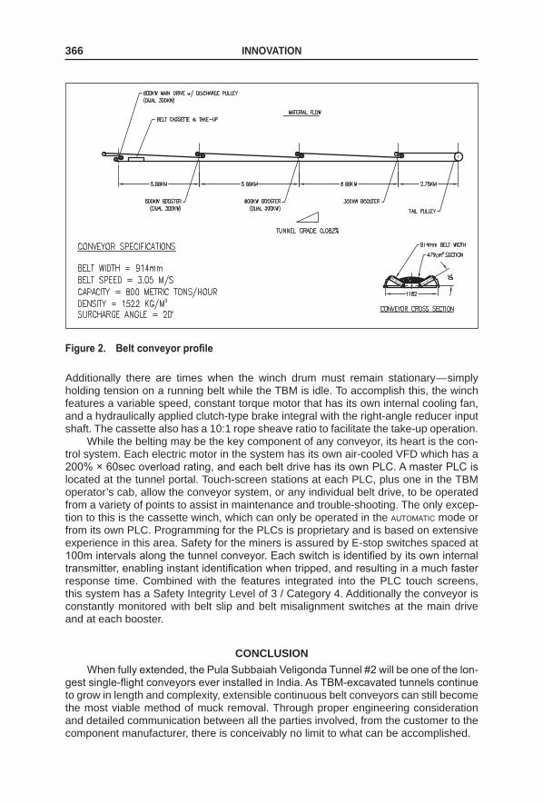
ous conveyor system with a design capacity of 800 metric tons per hour at a belt speed of 3.05 meters per second. With a peak volume capacity of over 1,500 tph, the 914mm belt-width conveyor can easily handle the ‘under ideal conditions’ TBM output for lim-ited periods of time. Despite the tunnel length, a single flight conveyor was preferred over a series of smaller cascading systems since it would not require the construction of any intermediate transfer stations and the loss of time in disassembling, relocating, and re-installing the major conveyor components (see Figure 2).
The key component of any belt conveyor is obviously the belting itself. For this system, an ST-1600 steel cable belt was selected. The belting has an ultimate strength of 1,600kN/m and a recommended operating strength of 240kN/m. Analysis of the con-veyor at its full 19.35km length by a proprietary computer program revealed that under natural load sharing, the conveyor would require 758kw at starting and 482kw during
.
Figure 1. Veligonda portal area

extensIBLe ConVeYoR sYsteMs 365
normal running. Belt tension at starting would peak at 36,044kg, while belt tension at running would decrease to 24,255kg, and the maximum belt tension at the articulated tail pulley in the back-up car would be 17,507kg and occur during starting. During nor-mal running conditions at its full length, the AutoBelt 2 computer program also indicated that the conveyor would require a belt with an operational rating of 260kN/m, which still fell within the ST-1600 operating parameters. The steel cable core is sandwiched between 5mm thick, flame resistant top and bottom covers. Permanent vulcanized splices were also specified as new belting is added into the system to maintain the integrity of the conveyor. An in-line splicing station between the main drive and the belt cassette is dedicated to this requirement.
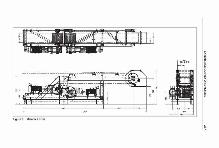
The belt drives for this system were designed with modular construction to allow for simplicity during manufacturing and interchangeability of component parts. The power units are self-contained and shaft-mounted utilizing a 300kw variable speed motor and a right angle hollow-shaft reducer. This configuration allows for easier ship-ping and faster assembly at the job site. The main drive (See Figure 3) consists of two power units (600kw total) with the drive pulleys mounted in the traditional tandem con-figuration and features an elevated, boom-mounted discharge pulley. The drive pulleys are also equipped with ceramic lagging to reduce belt slippage. The power units are mounted on the same side of the main frame to reduce the overall width and thereby minimize the footprint required by the main drive in the narrow confines of the starting trench.
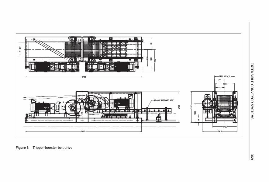
The tripper-booster drives (See Figure 4) also use the same 300kw power unit as the main drive. Two of the booster drives are rated at 600kw; however, booster #3 has only a single 300kw power unit. This is due to the spacing of the tripper-boosters along the tunnel length. The booster drives will be equally spaced at 5.66km intervals from the main drive. This positions booster #3 only 2.75km from the end of the tunnel and reduces the load it is required to carry. The tripper-boosters share nearly the same design advantages as the main drive, but feature a loading hopper and an impact bed instead of a discharge boom and pulley. Again, the 600kw boosters have the power units mounted on the same side to minimize the amount of space in the tunnel cross-section required to mount the booster.
No booster drive was required for the return side of the belt due to the absence of any curves along the tunnel centerline which would have induced a considerable amount of additional drag for a conveyor of this length. Had curves been present, Robbins’ patented curve carrying idlers and patented return hold-downs would have been specified, and the increase in return tension would have been reflected in the AutoBelt 2 printout. As it is, the running tension in the return side of the conveyor is only 12,827kg and is easily within the operating parameters of the ST-1600 belt. This also assumes that regular scheduled conveyor maintenance will keep the belt properly tracked as misalignment of the belt can and will increase belt tension as well as con-suming horsepower.
A 620m capacity belt storage cassette (See Figure 5) was specified to accept the 500m rolls of new belting while still having enough extra take-up capacity to accommo-date the belt stretch at startup. This is especially critical in a conveyor of this length, and was also a deciding factor in selecting steel cable belting, as its modulus of elasticity is dramatically lower than that of fabric carcass belting. The cassette has a 10:1 ratio of main carriage movement vs. belt taken up and features ten intermediate carriages to maintain proper belt separation, thereby further reducing the drag on the return side of the conveyor. This feature also optimizes the ability of the cassette to react to the various loading conditions the conveyor is subjected to during a typical mining shift. An equally crucial component in this operation is the 3900kg electric drum winch which either winds in the Ø13mm wire rope to pull the main carriage back and maintain proper belt tension, or releases it as the TBM advances and pulls belting out of the cassette.
366 InnoVAtIon
Additionally there are times when the winch drum must remain stationary—simply holding tension on a running belt while the TBM is idle. To accomplish this, the winch features a variable speed, constant torque motor that has its own internal cooling fan, and a hydraulically applied clutch-type brake integral with the right-angle reducer input shaft. The cassette also has a 10:1 rope sheave ratio to facilitate the take-up operation.
While the belting may be the key component of any conveyor, its heart is the con-trol system. Each electric motor in the system has its own air-cooled VFD which has a 200% × 60sec overload rating, and each belt drive has its own PLC. A master PLC is located at the tunnel portal. Touch-screen stations at each PLC, plus one in the TBM operator’s cab, allow the conveyor system, or any individual belt drive, to be operated from a variety of points to assist in maintenance and trouble-shooting. The only excep-tion to this is the cassette winch, which can only be operated in the automatic mode or from its own PLC. Programming for the PLCs is proprietary and is based on extensive experience in this area. Safety for the miners is assured by E-stop switches spaced at 100m intervals along the tunnel conveyor. Each switch is identified by its own internal transmitter, enabling instant identification when tripped, and resulting in a much faster response time. Combined with the features integrated into the PLC touch screens, this system has a Safety Integrity Level of 3 / Category 4. Additionally the conveyor is constantly monitored with belt slip and belt misalignment switches at the main drive and at each booster.
ConCLusIonWhen fully extended, the Pula Subbaiah Veligonda Tunnel #2 will be one of the lon-
gest single-flight conveyors ever installed in India. As TBM-excavated tunnels continue to grow in length and complexity, extensible continuous belt conveyors can still become the most viable method of muck removal. Through proper engineering consideration and detailed communication between all the parties involved, from the customer to the component manufacturer, there is conceivably no limit to what can be accomplished.
Figure 2. Belt conveyor profile
extensIBLe Co
nVeYoR sYsteM
s 367
Figure 3. Main belt drive

368 Inno
VAtIon
Figure 4. Belt cassette and take-up winch
extensIBLe Co
nVeYoR sYsteM
s 369
Figure 5. tripper-booster belt drive