Embed Size (px)
Citation preview

Extensible 3D (X3D) GraphicsExamples
Don Brutzman
Web3D 2007, Perugia Italy, 15 April 2007
Naval Postgraduate SchoolMonterey California USA

Web3D 2007 Symposium
Sunday-Thursday 15-19 April 2007University of Perugia, Umbria Italy
Sponsored by ACM SIGGRAPH in cooperation with EuroGraphics and
Web3D Consortium
http://www.web3D.org/web3d2007

Session 1: X3D Introduction
X3D Software Development Kit (SDK)Installing X3D-Edit and ExamplesInstalling Xj3D and an X3D PluginHistory, Goals, Development, Capabilities• Chapter 1: Technical Overview• X3D for Web Authors, Don Brutzman and
Leonard Daly, Morgan Kaufmann Publishers
Current Working Groups and Activities

Session 2: X3D Examples
Chapter 2: Geometry 1, Primitive Shapes Chapter 3: GroupingChapter 4: Viewing and NavigationChapter 5: Appearance, Materials, TexturesChapter 6: Geometry 2, Points Lines
PolygonsChapter 7: Event AnimationChapter 8: User Interactivity

Session 3: X3D Examples
Chapter 9: Event Utilities and ScriptingChapter 10: Geometry 3, Geometry2DChapter 11: Lighting and EnvironmentChapter 12: Environment SensorsChapter 13: Geometry 4, TrianglesChapter 14: PrototypesChapter 15: Metadata (online only)

Session 4: Scene Access Interface (SAI)
Alan Hudson, Yumetech
Installing Xj3DExamples directoryRunning in Netbeans

X3D Examples
Chapter by chapter, from
X3D for Web Authors

Chapter 1: Technical Overview
When we mean to build, we first survey the plot, then draw the model.
—William Shakespeare, Henry IV Part II Act 1 Scene 2
Chapter 1 is provided online.

Chapter 2: Geometry 1, Primitive Shapes
Dorothy in Oz: “Toto, I’ve a feeling we’re not in Kansas anymore.”
—L. Frank Baum, Wizard of Oz, 1939
BoxConeCylinder
SphereText

Geometry Primitives
Primitives are simple geometric constructsShape, geometry, Appearance, Material patternBrowsers decide implementation details,
including tessellation resolution

Chapter 2: Geometry 1, Primitive Shapes

X3D Specification Diagrams

Chapter 3: Grouping
A Working Group is a technical committee that researches and proposes solutions to specific technical problems relating to X3D.
—Web3D Consortium
InlineGroupStaticGroup
LOD (level of detail)SwitchTransform

Coordinate Systems
Right hand rule for X Y Z order
Y axis is up
Correspondence: North, Up, East
Accept no substitutes!• or at least realign them

Right-hand rule rules!
First three fingers of right hand must align with the X Y Z axes, in that order
Right hand rule also provides direction of positive rotation about an axis

Transforming shapes

LOD.jpg Near view Far view
Level of detail: LOD node
Range array values are suggested transition distancescontainerField name is children, not level

Switch node selects among children
Note whichChoice index starts at 0; -1 means noneChild-node containerField name is children, not choice

Chapter 4: Viewing and Navigation
But the eyes, though they are no sailors, will never be satisfied with any model, however fashionable, which does not answer all the requisitions of art.
—Henry David Thoreau, 1849
ViewpointNavigationInfo
AnchorBillboardCollision

Viewpoints

Billboard

NavigationInfo
avatarSize dimensions

Binding stack example timeline1
• t0. The initial loading of scene has first <Viewpoint DEF="View1"/> active and bound to the top of the binding stack. Other viewpoints are off the binding stack. If no viewpoints are provided in the scene, then the default <Viewpoint position="0 0 10"/> defined in the X3D Specification is used.
• t1. When the user selects View2 from the viewpoint list, it receives a set_bind true event and goes to the top of the binding stack. View2 also issues an isBound true event, and View1 issues an isBound false event as it moves down the stack.
• t2. Similar to the previous transitions in step t1, View3 receives a set_bind="true" event and responds with an isBound true event, while View2 issues an isBound false event and pushes View1 further down the stack.
• t3. View3 receives a set_bind false event, triggering a corresponding isBound false event and dropping off the stack completely. Because View2 is the next node on the binding stack, it pops to the top to become the active Viewpoint node. View2 also issues an isBound true event.
Binding stack example timeline2
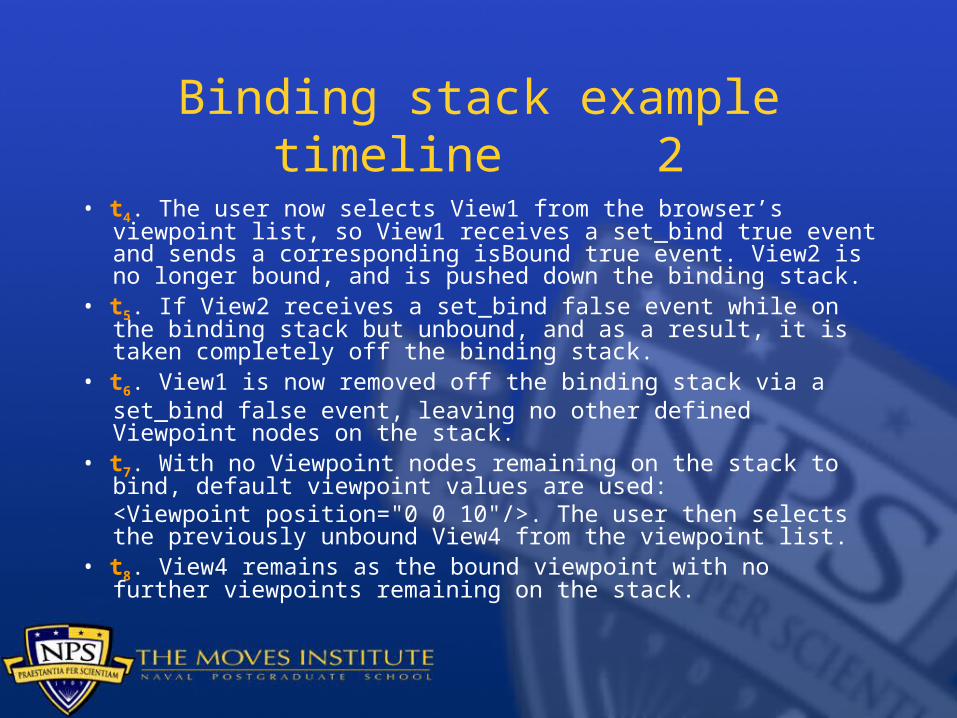
• t4. The user now selects View1 from the browser’s viewpoint list, so View1 receives a set_bind true event and sends a corresponding isBound true event. View2 is no longer bound, and is pushed down the binding stack.
• t5. If View2 receives a set_bind false event while on the binding stack but unbound, and as a result, it is taken completely off the binding stack.
• t6. View1 is now removed off the binding stack via aset_bind false event, leaving no other defined Viewpoint nodes on the stack.
• t7. With no Viewpoint nodes remaining on the stack to bind, default viewpoint values are used: <Viewpoint position="0 0 10"/>. The user then selects the previously unbound View4 from the viewpoint list.
• t8. View4 remains as the bound viewpoint with no further viewpoints remaining on the stack.

Binding stack example timeline3

Chapter 5: Appearance, Materials, Textures
Things are not always as they appear.
AppearanceMaterialImageTexture
MovieTexturePixelTextureTextureTransform

Chapter 6: Geometry 2, Points Lines Polygons
Drawing is a struggle between nature and the artist, in which the better the artist understands the intentions of nature, the more easily he will triumph over it. For him it is not a question of copying, but of interpreting in a simpler and more luminous language.
—Charles Baudelaire, On the Ideal and the Model, 1846
ColorColorRGBACoordinateCoordinateDoublePointSet
LineSetIndexedLineSetIndexedFaceSetElevationGridExtrusion

Convex and concave polygons
Mnemonic: concave polygons have a cavity

ElevationGrid nonplanar quadrilaterals
Ambiguous definition is unavoidable for this geometric representation
Usually not a problem; either masked or minor

Extrusion SCP:spine-aligned cross-section
plane

Extrusions with crossSection visible

Extrusion

Extrusion

Chapter 7: Event Animation
If it ain’t moving, it ain’t 3D.
—Andy van Dam, SIGGRAPH pioneer, Brown University, Providence Rhode Island
TimeSensorScalarInterpolatorColorInterpolatorPositionInterpolatorPositionInterpolator2D
OrientationInterpolatorNormalInterpolatorCoordinateInterpolatorCoordinateInterpolator2D

Event, behavior, ROUTE defined
Event = time-stamped value going over a ROUTEBehavior = changing a field value in a node
ROUTE connection enables the output field of one node to stimulate input field of another node• Field type and accessType must both match

X3D simple types, default values1
SFBool Single-Field boolean valuefalse (XML)FALSE (VRML)
MFBool Multiple-Field boolean array Empty list
SFColor Single-Field color, RGB 0 0 0
MFColorMultiple-Field color array RGB
Empty list
SFColorRGBA
Single-Field color, RGBA 0 0 0 0
MFColorRGBA
Multiple-Field color array RGB
Empty list

X3D simple types, default values2
SFInt32 Single-Field 32-bit integer value 0
MFInt32Multiple-Field 32-bit integer array
Empty list
SFFloatSingle-Field single-precision float
0.0
MFFloatMultiple-Field single-precision array
Empty list
SFDoubleSingle-Field double-precision float
0.0
MFDoubleMultiple-Field double-precision array
Empty list

X3D simple types, default values3
SFRotation
Single-Field rotation axis-angle value
0 1 0 0
MFRotation
Multiple-Field rotation axis-angle array
Empty list
SFString Single-Field string valueEmpty string ̎̎̎̎ ̎̎
MFString Multiple-Field string array Empty list
SFTime Single-Field time value-1 sentinel (no time)
MFTime Multiple-Field time array Empty list

X3D simple types, default values4
SFVec2f/SFVec2d
Single-Field vector of 2-float/2-double values
0 0
MFVec2f/MFVec2d
Multiple-Field vector array of 2-float/2-double values
Empty list
SFVec3f/SFVec3d
Single-Field vector of 3-float/3-double values
0 0 0
MFVec3f/MFVec3d
Multiple-Field vector array of 3-float/3-double values
Empty list

accessType values
X3D VRML97
inputOnly eventIn
outputOnly eventOut
initializeOnly field
inputOutput exposedField

TimeSensor
Output time is an SFTime ramp function ranging [0,1] that repeats every cycleInterval seconds

Designing animation chains
X3D can be imposing, there are many nodesNevertheless a simple design pattern is used
for nearly every kind of animation
This event ROUTE pattern enables you to expertly animate most X3D scene behaviors

10-step design of animation chains, 1
1. Pick target. Pick node and target field to animate (i.e., field that receives changing animation values).
2. Name target. Provide a DEF label for the node of interest, giving it a name.
3. Check animation type. Determine if the target field is a floating-point type: SFFloat, SFVec3f, MFVec3f, SFColor, and so on.• The target field is either singleton SF type or array MF
type. • In the X3D type-naming convention, SF means Single
Field, and MF means Multiple Field.• Check target field accessType is inputOnly or inputOutput.

10-step design of animation chains, 2
4. Determine whether Sequencer or Script. If the target type is an SFBool or SFInt32, use a sequencer node as event source. If the target type is an SFNode or MFNode, use a Script node as the event source.
5. Determine if Interpolator. If you are not using a sequencer or Script node, determine corresponding Interpolator which produces that type of value_changed output. Example: PositionInterpolator produces SFVec3f value_changed events.

10-step design of animation chains, 3
6. Triggering sensor. If desired, add a sensor node at the beginning of the chain to provide the appropriate SFTime or SFBool triggering input to start the animation. Sometimes the triggering event is an output from another animation chain.
7. TimeSensor clock. Add a TimeSensor as the animation clock, then set its cycleInterval field to the desired duration interval of animation.• Set loop='false' if an animation only runs once at
certain specific times.• Set loop='true' if it loops repeatedly.

10-step design of animation chains, 4
8. Connect trigger. ROUTE sensor or trigger node’s output field to the TimeSensor input in order to start the animation chain.
9. Connect clock. ROUTE the TimeSensor fraction_changed field to the interpolator (or sequencer) node's set_fraction field in order to drive the animation chain.
10. Connect animation output. ROUTE the interpolator, sequencer, or Script node's value_changed field to target node, field of interest in order to complete the animation chain.

Hello X3D Authors showing ROUTEs

Hello X3D Authors 10-step process

Interpolation
Interpolation is linear averaging applied 2 ways: first across time axis, then across value axis

Linear Interpolation
Piecewise-linear curve fitting can approximate any curve with arbitrary accuracy
Multi-field (MF) values are individually interpolated proportionately
key='0 0.3333 0.666 1'keyValue='1 0 0, 0 1 0,
0 0 1, 1 0 0'

Linear Interpolation
Step functions are created by repeating time values
key='0 0.25 0.25 0.5 0.5 1'
keyValue='1 1 2 2 3 4'
Note that time-fraction key array must always be monotonically increasing

ColorInterpolator example

ColorInterpolator scene graph

ColorInterpolator scene graph with ROUTEs

ColorInterpolator html pretty-print

Chapter 8: User Interactivity
Nobody knows the kind of trouble we’re in. Nobody seems to think it all might happen again.
—Gram Parson, One Hundred Years from Now
TouchSensorPlaneSensorCylinderSensor
SphereSensorKeySensorStringSensor

Use the description field
The description field allows the author to provide guidance text for each Sensor node
This is a great way to tell users what is happening in the scene, and what they should do to interact effectively
“Short and sweet” descriptions are best

CylinderSensor design pattern

CylinderSensor diskAngle mode determination

Chapter 9: Event Utilities and Scripting
Action is eloquence.
—William Shakespeare, Coriolanus, Act III, Scene II
BooleanFilterBooleanToggleBooleanSequencerBooleanTrigger
IntegerSequencerIntegerTriggerScript

Boolean, IntegerSequencer event timelines

IntegerSequencer event timeline

Script nodes
Script nodes are used to create special-purpose animation and computation capabilities.
Only create a Script when no other X3D node can get the job done
Script code can be written either in ECMAScript (also known as JavaScript) or Java• Future work: bindings for C++

X3D Execution Model

Script life cycle

examples/Basic/course/CreateVrmlFromStringRandomBoxes
.x3dscene graph

ECMAScript source code
<![CDATA[
ecmascript:
function R () {return Math.random();
}function recompute (isActive) {
if (isActive==true) initialize();}
function initialize() { for (i=0; i < 10; i++) { rand1 = 100*R(); rand2 = 100*R(); rand3 = 20*R(); rand4 = 40*R(); rand5 = 20*R(); sceneString = 'Transform { \n' + ' translation ' + rand1 + ' 0 ' + rand2 + ' children [ \n' + ' Shape { \n' + ' appearance Appearance { \n' + ' material Material { \n' + ' diffuseColor ' + R() + ' ' + R() + ' ' + R() + '\n' + ' } \n' + ' } \n' + ' geometry Box { \n' + ' size ' + rand3 + ' ' + rand4 + ' ' + rand5 + '\n' + ' } \n' + ' } \n' + ' ] \n' + '} \n' +
'#########################################################\n'; Browser.print (sceneString); newNode = Browser.createVrmlFromString(sceneString);// newNode = Browser.createX3dFromString(sceneString); ModifiableExternalNode.children[i] = newNode[0]; }}
]]>

10 random boxes snapshot

Chapter 10: Geometry 3, Geometry2D
Theorem. For a triangle with a right-angle between sides a and b, with hypotenuse c, a2 + b2 = c2
—Pythagoras
Arc2DArcClose2DCircle2DDisk2D
Polyline2DPolypoint2DRectangle2DTriangleSet2D

Arc2D, ArcClose2D

Chapter 11: Lighting and Environment
Daylight encourages good behavior.
—Don Brutzman
DirectionalLightPointLightSpotLight
BackgroundTextureBackgroundFog

Light, object, viewpoint relationships

DirectionalLight

PointLight

SpotLight

Chapter 12: Environment Sensors
Hereafter, when they come to model heav’nAnd calculate the stars, how they will wieldThe mighty frame, how build, unbuild,
contriveTo save appearances, how gird the sphereWith centric and eccentric scribbled o’er,Cycle and epicycle, orb in orb.
—John Milton, Paradise Lost, 1667
LoadSensorProximitySensorVisibilitySensor
SoundAudioClip

LoadSensor
LoadSensor keeps track of progress and completion when downloading external file resources.
LoadSensor can be used as a triggering node in event-animation chains.
This capability lets authors carefully delay the commencement of scene animations by waiting until relevant image textures, sounds, and X3D files are properly loaded before commencing an animation sequence.

LoadSensor tooltip page

Sound ellipses and attenuation

Sound ellipse major, minor axes

Min, maxHalfWidth derivations
helpful
for
Sound
authoring

Stereo pan calculations for sound

Chapter 13: Geometry 4, Triangles and Quadrilaterals
There is no “royal road” to geometry.
—Euclid, to King Ptolemy I
NormalTriangleSetTriangleStripSetTriangleFanSetQuadSet
IndexedTriangleSetIndexedTriangleStripSetIndexedTriangleFanSetIndexedQuadSet

Normal calculations

Chapter 14: Prototypes
There are more things in heaven and earth, Horatio, than are dreamt of in your philosophy.
—William Shakespeare, Hamlet Act I Scene V
ProtoDeclare (ProtoInterface, ProtoBody)
ExternProtoDeclare ProtoInstance

Prototype Declaration hints
Follow X3D naming conventions for node and field definitions.
Provide useful/safe default initialization values for each field, rather than depending on default field values internal to the ProtoBody.
Include annotation tooltips for each field.Avoid copying ProtoDeclare definitions into
additional scenes, instead copy ExternProtoDeclare and ProtoInstance definitions.
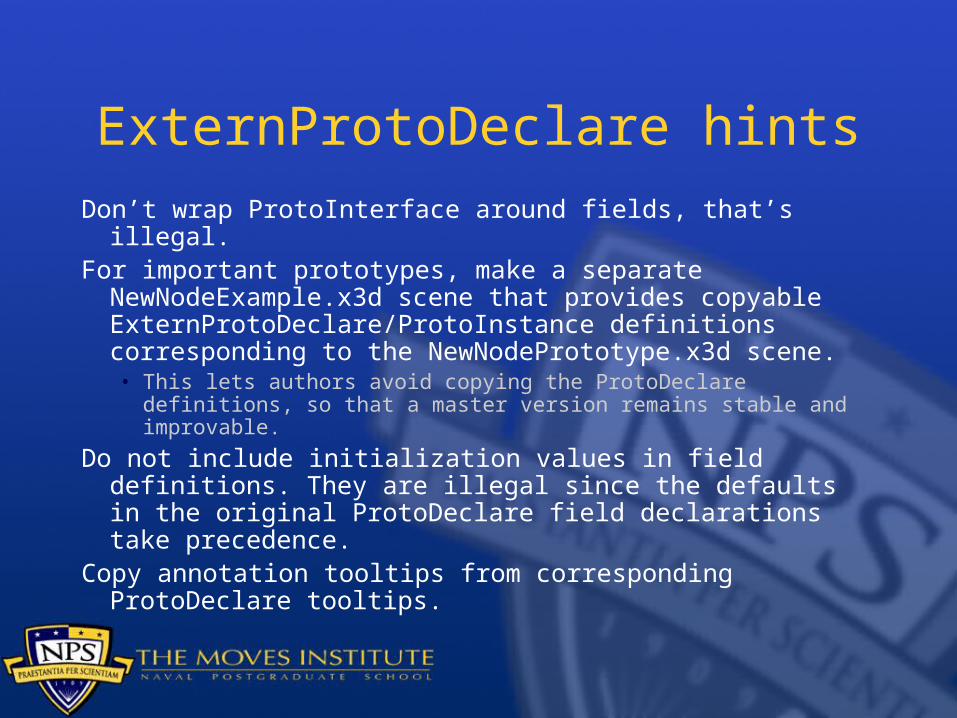
ExternProtoDeclare hintsDon’t wrap ProtoInterface around fields, that’s illegal.For important prototypes, make a separate
NewNodeExample.x3d scene that provides copyable ExternProtoDeclare/ProtoInstance definitions corresponding to the NewNodePrototype.x3d scene. • This lets authors avoid copying the ProtoDeclare definitions,
so that a master version remains stable and improvable.
Do not include initialization values in field definitions. They are illegal since the defaults in the original ProtoDeclare field declarations take precedence.
Copy annotation tooltips from corresponding ProtoDeclare tooltips.

ProtoInstance hintsExplicitly include initialization values, even if they match
default values, to ensure proper operation. Sometimes a prototype has different initialization values than expected, if modified elsewhere.
Remember to include proper containerField attribute, identifying parent-node field name for this ProtoInstance. Default value: children. Example values: color, coord, geometry, fontStyle, proxy, sound, texture, textureTransform.
First debug proper ProtoInstance operation in the scene defining the original ProtoDeclare, rather than using ExternProtoDeclare. Why – make sure it works first! • Browser debugging can be more cryptic for externally defined
prototypes and different versions may occur in various remote url addresses, making it difficult to determine precisely which ExternProtoDeclare is being referenced.

Chapter 15: Metadata (online only)
Metadata defined: in general, "data about data;" functionally, "structured data about data." Metadata includes data associated with either an information system or an information object for purposes of description, administration, legal requirements, technical functionality, use and usage, and preservation.
--Dublin Core Metadata Initiative (DCMI)
WorldInfoMetadataIntegerMetadataFloat
MetadataDoubleMetadataStringMetadataSet
Chapter 15 will be provided online.

Conclusions and Recommendations
X3D is a cool language. Authoring can be fun!
Many resources, tools and examples are now available, more than ever before.
Lots of important work remains. You can help. Together we are building the 3D Web.

Don Brutzman
[email protected] http://web.nps.navy.mil/~brutzman
Code USW/Br, Naval Postgraduate SchoolMonterey California 93943-5000 USA
1.831.656.2149 voice1.831.656.7599 fax
Contact