Embed Size (px)
Citation preview
CER
N-S
PSC
-201
6-03
6/
SPSC
-EO
I-01
405
/10/
2016
Expression of Interest
Enabling precise measurements of flux inaccelerator neutrino beams: the ENUBET project
A. Berraa,b, M. Bonesinib, C. Brizzolaria,b, M. Calvianim, M.G. Catanesil,S. Cecchinic, F. Cindoloc, G. Collazuolk,j, E. Contij, F. Dal Corsoj, G. De Rosap,q,A. Golao, R.A. Intontil, C. Jolletd, M. Lavederk,j, A. Longhinj(∗), P.F. Loverren,f ,
L. Ludovicif , L. Magalettil, G. Mandriolic, A. Margottic, N. Mauric, A. Meregagliad,M. Mezzettoj, M. Nessim, A. Paolonie, L. Pasqualinic,g, G. Paternostero, L. Patriziic,
C. Piemonteo, M. Pozzatoc, M. Presta,b, F. Pupillie, E. Radicionil, C. Ricciop,q,A.C. Ruggerip, G. Sirric, F. Terranovab,h, E. Vallazzai, L. Votanoe, E. Wildnerm
a Phys. Dep. Universita degli Studi dell’Insubria, via Valeggio 11, Como, Italyb INFN, Sezione di Milano-Bicocca, Piazza della Scienza 3, Milano, Italy
c INFN, Sezione di Bologna, viale Berti-Pichat 6/2, Bologna, Italyd IPHC, Universite de Strasbourg, CNRS/IN2P3, Strasbourg, France
e INFN, Laboratori Nazionali di Frascati, via Fermi 40, Frascati (Rome), Italyf INFN, Sezione di Roma 1, piazzale A. Moro 2, Rome, Italy
g Phys. Dep. Universita di Bologna, viale Berti-Pichat 6/2, Bologna, Italyh Phys. Dep. Universita di Milano-Bicocca, Piazza della scienza 3, Milano, Italy
i INFN Sezione di Trieste, via Valerio, 2 - Trieste, Italyj INFN Sezione di Padova, via Marzolo, 8 - Padova, Italy
k Phys. Dep. Universita di Padova, via Marzolo, 8 - Padova, Italyl INFN Sezione di Bari, via Amendola, 173 - Bari, Italy
m CERN, Geneva, Switzerlandn Phys. Dep. Universita La Sapienza, piazzale A. Moro 2, Rome, Italyo Fondazione Bruno Kessler (FBK) and INFN TIFPA, Trento, Italy
p INFN, Sezione di Napoli, via Cinthia, 80126, Napoli, Italyq Phys. Dep. Universita degli Studi di Napoli Federico II, via Cinthia, 80126, Napoli,
Italy(∗) Contactperson
Abstract
The knowledge of the initial flux in conventional neutrino beams represents themain limitation for a precision (1%) measurement of νe and νµ cross sections.The progress in fast and radiation–hard detectors offers an unprecedented oppor-tunity to monitor lepton production in the decay tunnel of conventional neutrinobeams and, hence, reduce the flux uncertainty by about one order of magnitude.The opportunities and challenges of this novel approach are the focus of theEnubet project, which has been recently approved by the European ResearchCouncil (ERC Consolidator Grants 2015, Grant Agreement 681647). In this Ex-pression of Interest we present the Enubet physics programme with emphasison the activities that can be carried out in collaboration with CERN. We discussthe relevance of Enubet in the framework of the CERN Neutrino Platform andhighlight synergies with the CERN programme in particle physics and acceleratorscience.

1 Introduction
The challenges of neutrino physics for the next decade reside in the observation ofsmall perturbations of the leading oscillation probabilities at long and short–baselineexperiments. Such perturbations encode effects due to CP violation in the leptonicsector, the neutrino mass hierarchy and the presence of additional light neutrino statesthat are singlets in the Standard Model (SM) gauge groups. None of these challengescan be tackled effectively if the SM properties of neutrinos are poorly known, firstly theSM ν cross-sections [1, 2]. The need for precise measurements of these quantities hasboosted a rich experimental programme in the US [3, 4, 5, 6] and Japan [7, 8, 9, 10],which achieved impressive results in the last ten years [11]. On the other hand, ourknowledge of the neutrino cross sections remains limited by the knowledge of the initialfluxes in conventional neutrino beams. This represents an intrinsic limitation of anybeam that produces neutrinos from pion decays: the yield of νµ is not monitored ina direct manner (i.e. through the precise counting of the parent pions) but relieson extrapolation from hadro-production data and a careful simulation of the neutrinobeamline. This limitation bounds the precision that can be reached in the measurementof the absolute cross sections to O(5 − 10%) [12, 13, 14]. In addition, pion-basedsources mainly produce νµ while most of the next generation oscillation experimentswill rely on the appearance of νe at the far detector. A direct measurement of theνe cross sections is, hence, desirable since extrapolations from νµ introduce additionaluncertainties [15]. Finally, high precision oscillation experiments [16, 17, 18] need acareful determination of the product ε(E) ·σνe(E), i.e. the detector efficiency times thecross section for νe CC: measuring ε(E) · σνe(E) from a well controlled source of νe isthus of great practical interest. Novel neutrino sources as the Neutrino Factories andthe Beta Beams can overcome these limitations and provide intense and well controlledsources of νe beams. In particular, the proposed nuSTORM [19] facility - which is basedon neutrino production from muon decays and, hence, represents a major leap towarda Neutrino Factory - can achieve a O(1%) precision on absolute cross sections.
While muon-based neutrino beams can be considered the ultimate facility for crosssection measurements, π/K neutrino beams still have a large potential to improve fluxsystematics [20]. A very straightforward technique to bring flux systematics below 1%takes advantage of three-body semileptonic decays of charged kaons. Neutrino beamsin the O(1 − 10) GeV energy range can be obtained from the decay in flight of pionsand kaons in a short decay tunnel (< 50 m, see below). In such beams, the dominantsource of νe is K+ → e+νeπ
0 (Ke3), while νe from muon decays are strongly suppressed.
In beamlines where νe are produced just by Ke3, the electron-neutrino flux canbe monitored very precisely by the observation of large angle positrons in the decaytunnel. Lepton tagging is a standard technique in kaon physics but, despite severalproposals [21, 22, 23, 24, 25], this technique has never been upscaled to intensitiesrelevant for neutrino physics because the overall kaon tagging rate is limited to a fewGHz. Cross section measurements, however, do not need an event-by-event tag of the
2
kaons: monitoring the local positron production rate along the decay tunnel is sufficientto keep the νe yield uncertainty at the per cent level if Ke3 is the only source of νe atthe far detector [26, 27].
Due to the short source-to-detector distance in neutrino cross section experiments,the integrated protons-on-target (pot) that are needed to reach a statistical preci-sion below 1% are well within the reach of present accelerators. This possibility hasbeen explored in Ref. [27], where it has been shown that all major proton driversat FERMILAB, CERN and J-PARC can be fruitfully employed to perform a ∼ 1%precision measurement of the νe cross section even with a ∼ 500 t mass neutrino de-tector. Since detectors of this size are either under construction or envisaged in theselaboratories for sterile neutrino searches (FERMILAB [28]), neutrino detector R&D(FERMILAB,CERN [29, 30]) and as near detectors of long baseline experiments (J-PARC [31, 32]), the possibility of exploiting Ke3 is of great practical value. It is alsoworth recalling that these detectors are all built upon the technologies that will beused for the next generation of long baseline experiments, i.e. Liquid Argon TPC andWater Cherenkov. This allows to measure the cross-sections directly on the nucleartargets used in the oscillation experiments, without relying on extrapolation of thenuclear effects. Moreover, sharing similar detector technique, some of the systematicuncertainties would cancel when comparing the number of expected events ε(E)·σνe(E).
This novel approach to determine the neutrino flux through the direct measurementof the accompanying positrons in Ke3 decays, will be tested in a conclusive manner byEnubet (“Enhanced NeUtrino BEams from kaon Tagging”). The Enubet projectis intended to build a detector capable of performing positron identification in Ke3
decays while operating in the harsh environment of a conventional neutrino beam de-cay tunnel. The project will address all accelerator challenges of kaon tagged beamsand study the precise layout of the kaon/pion focusing and transport system (hadronbeam) capable of producing a beam suited for large angle positron monitoring. Thisproject has been recently approved by the European Research Council (ERC Consol-idator, PI A. Longhin, Host Institution INFN, Grant Agreement 681647) for a fiveyear duration and a 2.0 Me budget. The project started on 1 June 2016 and theEnubet Collaboration is being formed.
The Enubet physics programme is strongly synergic with CERN activities in neu-trino physics (the CERN Neutrino Platform) and the CERN fixed-target programme.Several accelerator challenges are also shared with the proposed SHiP experiment.
In this document we describe the Enubet R&D programme with emphasis onthe activities that can be carried out taking advantage of existing CERN facilities ordeveloped in collaboration with CERN EP and AST. We will also highlight synergieswith the CERN physics programme in particle physics and accelerator science.
3
2 The ENUBET project
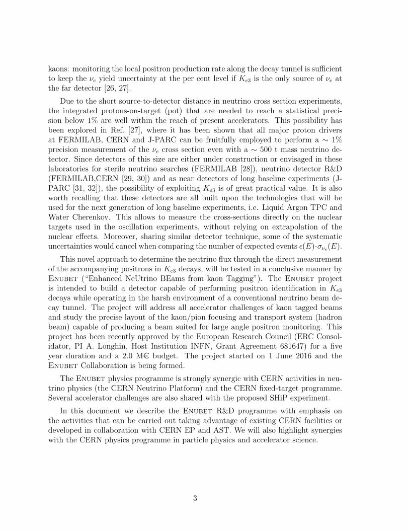
The exploitation of kaon tagging in neutrino beams of intensities suited for νe or νe crosssection measurements requires a very specific extraction and transport line. The beam-line (see Fig. 1) selects secondaries within a given momentum bite and only positive(negative) particles are transported to the decay tunnel during the neutrino (anti–neutrino) run. Neutrals and non-interacting protons are separated at the first bendingdipole and dumped in the proximity of the target area.
Figure 1: Schematic layout of the tagged neutrino beam facility (proton dump notshown).
The secondary beam is transported to a decay tunnel that is instrumented to detectthe positron (electron) accompanying the electron neutrinos (anti–neutrinos) producedin Ke3 decays. The rejection of charged pions and converted photons can be achieved byfast calorimeters (“taggers”) with longitudinal segmentation (see Sec. 4) and a photonveto (“t0 layer”) (see Sec. 5). The detector choice must be cost-effective since a largepositron efficiency is reached only when a significant fraction of the decay tunnel isinstrumented. The conceptual layout is completed by a charged particle dump at theend of the decay tunnel and a short baseline neutrino detector. Even if the challengeposed by a positron-tagged neutrino beam (see Sec. 3) seems to be within reach ofcurrent detector and accelerator technologies, a concrete layout of the tagger, t0 layerand of a beam-line compatible with the operation mode of accelerators at FERMILAB,CERN and J-PARC has not been put forward, yet.
Enubet will demonstrate the possibility of producing a neutrino beam with kaontagging. The goals of the project, corresponding to the five Enubet Working Packages(WP), are:
• WP1 (beamline): studying the precise layout of the kaon/pion focusing andtransport system (hadron beam) capable of producing beams with momentumand angular distributions suited for a positron-tagged neutrino beam.
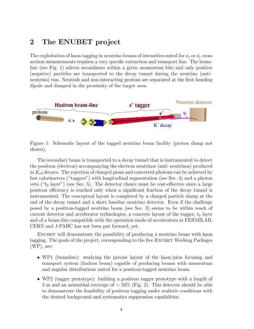
• WP2 (tagger prototype): building a positron tagger prototype with a length of3 m and an azimuthal coverage of ∼ 50% (Fig. 2). This detector should be ableto demonstrate the feasibility of positron tagging under realistic conditions withthe desired background and systematics suppression capabilities.
4
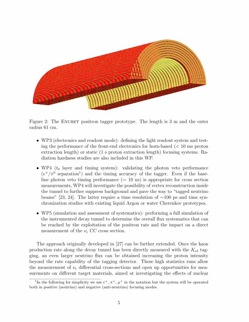
Figure 2: The Enubet positron tagger prototype. The length is 3 m and the outerradius 61 cm.
• WP3 (electronics and readout mode): defining the light readout system and test-ing the performance of the front-end electronics for horn-based (< 10 ms protonextraction length) or static (1 s proton extraction length) focusing systems. Ra-diation hardness studies are also included in this WP.
• WP4 (t0 layer and timing system): validating the photon veto performance(e+/π0 separation1) and the timing accuracy of the tagger. Even if the base-line photon veto timing performance (∼ 10 ns) is appropriate for cross sectionmeasurements, WP4 will investigate the possibility of vertex reconstruction insidethe tunnel to further suppress background and pave the way to “tagged neutrinobeams” [23, 24]. The latter require a time resolution of ∼100 ps and time syn-chronization studies with existing liquid Argon or water Cherenkov prototypes.
• WP5 (simulation and assessment of systematics): performing a full simulation ofthe instrumented decay tunnel to determine the overall flux systematics that canbe reached by the exploitation of the positron rate and the impact on a directmeasurement of the νe CC cross section.
The approach originally developed in [27] can be further extended. Once the kaonproduction rate along the decay tunnel has been directly measured with the Ke3 tag-ging, an even larger neutrino flux can be obtained increasing the proton intensitybeyond the rate capability of the tagging detector. These high statistics runs allowthe measurement of νe differential cross-sections and open up opportunities for mea-surements on different target materials, aimed at investigating the effects of nuclear
1In the following for simplicity we use e+, π+, µ+ in the notation but the system will be operatedboth in positive (neutrino) and negative (anti-neutrino) focusing modes.
5

dynamics in νe CC interactions. Moreover the large angle νµ CC events in the neutrinodetector are all due to neutrinos produced in Kµ3 decays and then, once the kaon pro-duction rate is measured with the Ke3 tagging, this gives access to the measurementof the absolute νµ CC cross section. The overall impact of the Enubet technique willhence be evaluated in the general framework of high precision cross section measure-ments for the DUNE/Hyper–Kamiokande era.
3 Constraints and challenges for positron tagging
Enabling direct monitoring of the νe by the observation of positrons from Ke3 posesconstraints on the design of the beamline and on the instrumented decay tunnel. Theseconstraints were reviewed in [27] and are summarized as follows.
3.1 Beamline parameters
The Enubet technology is particularly effective if νe from Ke3 are the only source ofνe at the far detector and their energy spectrum is in the range of interest for futureaccelerator neutrino experiments (0.5-10 GeV). Moreover, the positron spectrum hasto be in the GeV range to allow for e+/π+ separation from longitudinal sampling.For instance, if the beamline parameters are tuned for the neutrino energy range ofHyperkamiokande and DUNE, the extraction and focusing of secondary pions andkaons has to be peaked at 5-8 GeV and the length of the decay tunnel must be shorterthan 50 m in order to increase the νe/νµ ratio and reduce the contamination of νe frommuon decays in flight.
In the Enubet reference design, the tagging detector, i.e. the instrumentationmonitoring the large angle positrons, is a hollow cylinder of 40 cm inner radius, sur-rounding all or a fraction of the 50 m long decay volume. The secondary beam hasan average momentum of 8.5 GeV and a momentum bite of ± 20%. If the polar angledistribution is within a few mrad, the secondary beam reaches the beam dump with-out crossing the tagger. Since at this energy the decay cone of π+ → µ+νµ is 4 mrad,muons from pion decays reach the beam dump without crossing the tagger, too.
The tagging detector can be safely operated (pile-up, dose, etc.) if local particlerates are below ∼ 1 MHz/cm2. Hence, the proton extraction length cannot be reducedbelow 1 ms. Extractions significantly longer than 10 ms are also disfavored if secondaryfocusing is achieved by magnetic horns.
3.2 Background
Within the geometrical acceptance of the tagger the dominant background is due toK+ → π+π0 (Kπ2). An effective e+/π+ separation (at the level of few per cent for
6

∼ 50% efficiency) is needed to select a pure Ke3 sample. This performance can beachieved in the few GeV energy range by sampling calorimeters with longitudinal seg-mentation. Photon conversion from π0 decays must be suppressed by a photon veto.The veto (i.e. the t0 layer) also provides coarse information on the impact point of theparticle and the absolute time of the event. For cross section measurements, the timeaccuracy is not critical and should be of the order of the recovery time of the tagger(∼ 10 ns). It must be ∼100 ps if we aim at identifying particles belonging to thesame kaon decay vertex along the tunnel (see Sec. 5) to achieve additional backgroundreduction. Finally, the t0 layer and the positron tagger must be operated inside theevacuated (<1 mbar) beam-pipe to reduce photon conversion.
The constraints of Sec. 3.1 and 3.2 impose three critical choices. Firstly, on thecalorimeter and readout technology for the positron tagger. This choice will mostlybe driven by the e+/π+ separation capability, the maximum operating rate, pile-upreduction and cost-effectiveness. The same considerations hold for the t0 layer wherethe key parameters will be e+/γ separation capability and the material budget. Finallythere are specific requirements for the proton extraction scheme which in turnimpacts the choice of the technology for the secondary beam focusing and transport.This scheme must be compatible with standard operation modes of accelerators atFERMILAB, CERN and J-PARC.
4 The positron tagger
Positron identification at the few-GeV energy scale can be achieved employing fastcalorimeters with longitudinal segmentation. Charge exchange limits the e+/π+ sep-aration capability of this technique to ∼ 99%, which is appropriate for the aim ofcross section measurements. Sampling calorimeters with plastic scintillators are theoption of choice for an instrumented decay tunnel since they are fast (recovery time∼ 10 ns), cost-effective and their response to charged particles can be characterizedwith high precision. Unlike standard applications at colliders, however, charged parti-cles are produced here at any point along the decay tunnel and the average polar angledepends on the initial momentum of the parent particle and the three body kinematicsof kaon decay. The ideal solution is thus a calorimeter that is projective on the averageemission angle of the positrons (88 mrad for the setup considered in [27]) and exhibitslongitudinal segmentation.
In “shashlik” calorimeters [34] the stack of alternating slices of absorber and scintil-lator materials is penetrated by a wavelength shifting fiber (WLS) running perpendic-ular to the absorber and scintillator tiles. Shashlik calorimeters offer the most flexibledesign since the projection angle is defined by the direction of the WLS fibers. On theother hand, this setup is not generally suited for longitudinal segmentation since thefibers must be grouped and coupled to photomultipliers at the back of the stack [35].The shashlik layout can be adapted to longitudinal sampling replacing the PMT-based
7
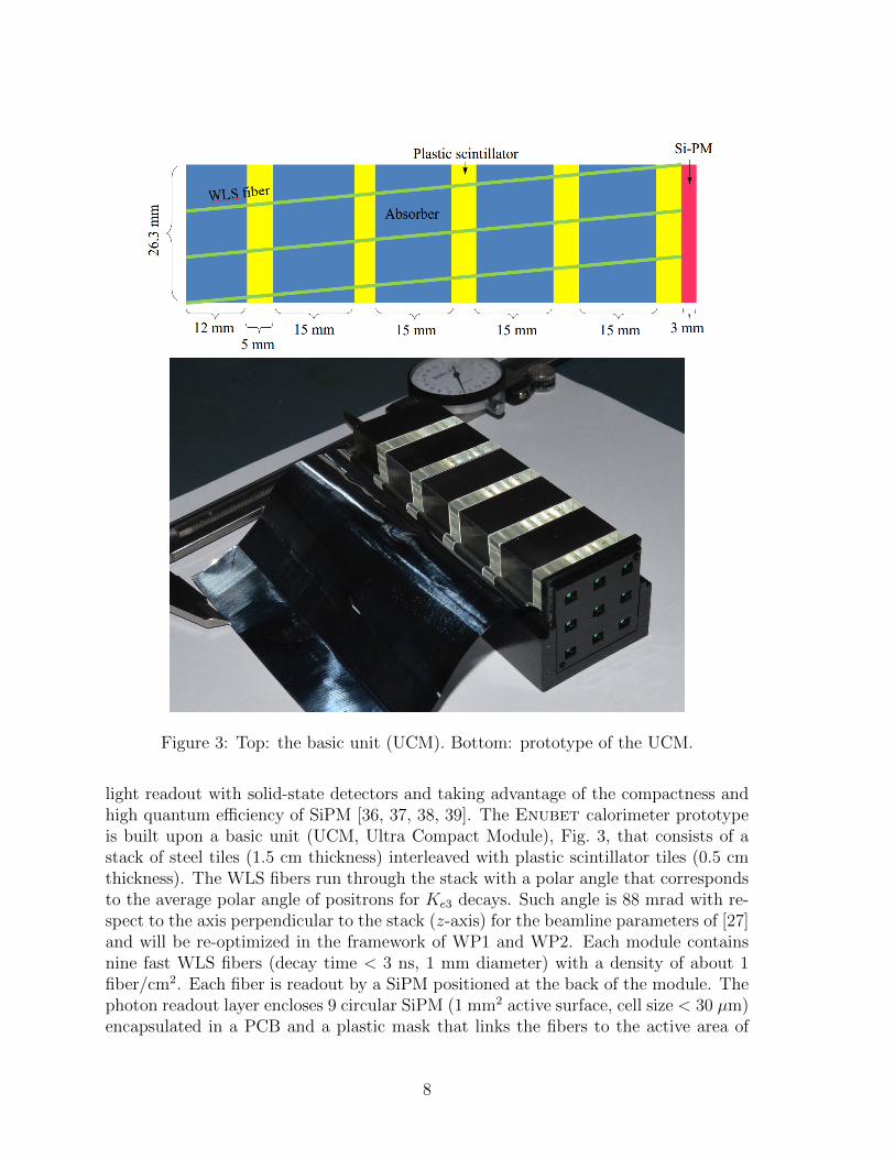
Figure 3: Top: the basic unit (UCM). Bottom: prototype of the UCM.
light readout with solid-state detectors and taking advantage of the compactness andhigh quantum efficiency of SiPM [36, 37, 38, 39]. The Enubet calorimeter prototypeis built upon a basic unit (UCM, Ultra Compact Module), Fig. 3, that consists of astack of steel tiles (1.5 cm thickness) interleaved with plastic scintillator tiles (0.5 cmthickness). The WLS fibers run through the stack with a polar angle that correspondsto the average polar angle of positrons for Ke3 decays. Such angle is 88 mrad with re-spect to the axis perpendicular to the stack (z-axis) for the beamline parameters of [27]and will be re-optimized in the framework of WP1 and WP2. Each module containsnine fast WLS fibers (decay time < 3 ns, 1 mm diameter) with a density of about 1fiber/cm2. Each fiber is readout by a SiPM positioned at the back of the module. Thephoton readout layer encloses 9 circular SiPM (1 mm2 active surface, cell size < 30 µm)encapsulated in a PCB and a plastic mask that links the fibers to the active area of
8
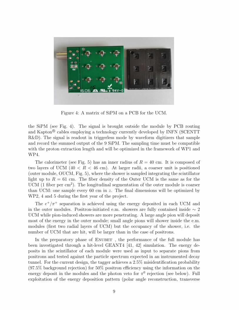
Figure 4: A matrix of SiPM on a PCB for the UCM.
the SiPM (see Fig. 4). The signal is brought outside the module by PCB routingand Kapton R© cables employing a technology currently developed by INFN (SCENTTR&D). The signal is readout in triggerless mode by waveform digitizers that sampleand record the summed output of the 9 SiPM. The sampling time must be compatiblewith the proton extraction length and will be optimized in the framework of WP1 andWP4.
The calorimeter (see Fig. 5) has an inner radius of R = 40 cm. It is composed oftwo layers of UCM (40 < R < 46 cm). At larger radii, a coarser unit is positioned(outer module, OUCM, Fig. 5), where the shower is sampled integrating the scintillatorlight up to R = 61 cm. The fiber density of the Outer UCM is the same as for theUCM (1 fiber per cm2). The longitudinal segmentation of the outer module is coarserthan UCM: one sample every 60 cm in z. The final dimensions will be optimized byWP2, 4 and 5 during the first year of the project.
The e+/π+ separation is achieved using the energy deposited in each UCM andin the outer modules. Positron-initiated e.m. showers are fully contained inside ∼ 2UCM while pion-induced showers are more penetrating. A large angle pion will depositmost of the energy in the outer module; small angle pions will shower inside the e.m.modules (first two radial layers of UCM) but the occupancy of the shower, i.e. thenumber of UCM that are hit, will be larger than in the case of positrons.
In the preparatory phase of Enubet , the performance of the full module hasbeen investigated through a hit-level GEANT4 [41, 42] simulation. The energy de-posits in the scintillator of each module were used as input to separate pions frompositrons and tested against the particle spectrum expected in an instrumented decaytunnel. For the current design, the tagger achieves a 2.5% misidentification probability(97.5% background rejection) for 50% positron efficiency using the information on theenergy deposit in the modules and the photon veto for π0 rejection (see below). Fullexploitation of the energy deposition pattern (polar angle reconstruction, transverse
9

Figure 5: A full module composed of two inner layers (6 UCM/layer) and six outerlayers (one OUCM/layer).
development of the shower and additional pointing information from the t0 layers) isin progress within WP5.
The CERN East Area represents the ideal infrastructure to test the Enubet pro-totypes before the LHC long shutdown 2 (LS2) and the final calorimeter (after LS2).The CERN-PS provides pions and electrons in the energy range of relevance for Enu-bet (1-4 GeV) and the structure of the spill (400 ms slow extraction) allows for testsin triggered and triggerless modes. In addition, the East Area beamlines are equippedwith ancillary instrumentation for electron tagging (Cherenkov counters), momentumbite selection (user setting for collimators) and particle tracking (wire chambers). Beamrequests for 2017-2018 will mainly be addressed for the T9 beamline (2-3 weeks peryear) in order to characterize the calorimeter prototype and the calorimeter + t0 layersystem (see below).
The aim of the tests are to:
• establish the performance of the positron tagger and the effectiveness of theshashlik layout enhanced by the longitudinal sampling. Tests will include themeasurement of the energy resolution for electrons and hadrons between 1 and5 GeV, the study of e+/π+ separation and a detailed characterization of lateralleakage.
• determine the maximum particle rate that can be sustained by the tagger withoutcompromising the particle identification performances.
10

• characterize the response of the tagger in order to maintain the flux systematicsdue to particle identification and efficiency below 1%.
• provide information to further optimize the detector granularity and reach thebest price-performance ratio. This optimization includes the size of the SiPM toprevent saturation, the number of SiPM to be summed and the parameters ofthe waveform digitizers.
In addition, the new EHN1 facility hosting the Liquid Argon prototypes gives inter-esting opportunities to combine the timing performance of the Enubet tagger with aneutrino detector. This phase addresses the issue of time coincidences between the lep-ton detection in the decay tunnel and the neutrino interaction (“time–tagged neutrinobeam”). These possibilities will be investigated after LS2 with the groups involved inthe Neutrino Platform either using cosmic rays or by parasitic runs with halo muonsat EHN1.
Since the positron tagger in the proposed design is supposed to be operated inside anevacuated beam-pipe (< 1 mbar), vacuum and degassing tests will also be performed.Radiation hardness is not expected to be a critical parameter except for the long-termsensitivity of SiPM to minimum ionizing particles. To address this issue direct testson individual UCM and specific detector components will be carried out, too.
5 The t0 layer
Beyond π+ → e+ misidentification, the next to leading source of background in thepositron sample is due to photons originating from K+ → π+π0 (Kπ2) decays andreaching the positron tagger [27]. A photon veto is needed to remove this contamina-tion; the veto also provides coarse information on the impact point of the particle andthe absolute time of the event. The baseline option for the t0 layer relies on standardtechnologies. In this configuration, the basic unit is a doublet of plastic scintillatortiles. Each tile, with a ∼ 3 × 3 cm2 surface and a 0.5 cm thickness, is readout by aWLS fiber [43, 44] optically linked to a SiPM. The doublet is mounted below the innerradius of the calorimeter and the planes are oriented parallel to the scintillator tiles ofthe positron tagger (see Fig. 2). Adjacent tiles form a ring (inner radius: 37 cm, outerradius: 40 cm) installed inside the positron tagger. Along the z-axis, t0 layer rings arelocated at a distance of D = 7 cm. Since all particles originating from kaon decays areemitted with polar angles smaller than 400 mrad, the distance among rings is chosen inorder to have at least one doublet that is hit by any particle reaching the positron tag-ger. On average, a positron reaching the calorimeter will hit 5 doublets. The thicknessof each doublet corresponds to ∼ 0.02 radiation lengths (X0). A positron (or electron)is defined as an energy deposit in the calorimeter compatible with an e.m. shower (seeSec. 4) and giving hits in the first doublet that are compatible with a mip (1 mip hitin each of the two layers). This requirement will veto the vast majority of photons
11

from Kπ2. A doublet layout is useful to remove the remaining photons, i.e. photonsthat convert into a e+e− pair in the first layer of the doublet (conversion probability:∼ 6× 10⁻³) and release an energy compatible with a mip. These particles will also bevetoed since they will deposit an energy compatible with two mips in the second layerof the doublet. In the preparatory phase of Enubet , the performance of the t0 layerin the baseline design has been evaluated and a 99% photon rejection efficiency hasbeen confirmed. The development of the t0 layer will be the main aim of WP4.
The baseline option for the t0 layer is appealing because the underlying detectortechnology is very well established. In this context, the main challenges (to be testedwithin Enubet) are to:
• develop a readout system that does not increase substantially the material budgetand does not compromise cost-effectiveness
• optimize the number of channels exploiting the tracking capability of the t0 layer(not exploited yet in the preparatory phase of Enubet) to improve backgroundsuppression
• validate the 1-mip versus 2-mip separation capability and the background inducedby lateral calorimeter leakage and albedo.
The baseline option has drawbacks that are worth being noticed. The doubletlayout implies a doubling of the readout channels and the use of a small area photoncounter (SiPM) coupled to a WLS reduces the photon collection efficiency.
Modern silicon detectors offer very interesting alternatives. For silicon counters,the material budget is much smaller than plastic scintillators (200 µm thickness, cor-responding to 2× 10−3 X0 versus 0.5 cm, corresponding to 1.2× 10−2 X0) and, hence,the doublet layout can be dropped off. In addition, the ion-hole pairs are collectedalong the whole electrode surface resulting into higher collection efficiencies and better1-mip vs 2-mip separation.
Standard silicon pads [45, 46] can be fruitfully employed at the price of a deterio-ration of the time resolution (which is, however, not crucial for the cross section mea-surement). As an alternative, Low-Gain Avalanche Detectors can bring large surface(1 cm2) silicon detectors to time resolution even better than standard scintillators [47].This solution is particularly interesting because a time resolution of ∼ 100 ps wouldopen up the possibility to exploit time coincidence to identify particles belonging tothe same kaon decay vertex along the tunnel [27]. As a consequence, further reductionof the Kπ2 and K+ → π+π+π− background would be achieved vetoing candidate Ke3
events with identified pions. Finally, a t0 layer with 100 ps time resolution combinedwith fast readout of Cherenkov [48, 49] and scintillator light [50] in neutrino detectorswould be a major step toward the realization of “tagged neutrino beams”, i.e. sources
12

that exploit the time coincidence of the positron in the decay tunnel and the νe inter-action at the detector. Enubet will thus provide a proof-of-principle of the baselinedesign and investigate the two silicon-based options mentioned above.
The t0 layer prototypes will be tested in standalone mode at the INFN-LNF BeamTest Facility (BTF). The combined setup (calorimeter equipped with the t0 layer) willbe tested at CERN employing the PS East Area beamlines.
6 Proton extraction scheme and focusing system
Even with a moderate neutrino detector mass, a cross section experiment aiming at astatistical error < 1% will not challenge current neutrino beams in term of integratedprotons on target. For a 500 t neutrino detector located 100 m from the entrance of thedecay tunnel (50 m from the beam dump) and a 30 GeV (450 GeV) proton driver, themeasurement will be systematics limited for 5× 10²⁰ (5× 10¹⁹) pot [27]. On the otherhand, the average power during extraction or, equivalently, the number of secondariescrossing the instrumented tunnel per unit time must be limited to reduce pile-up inthe positron tagger and in the t0 layer.
At the CERN SPS (450 GeV protons) a maximum particle rate of 500 kHz/cm2 onthe tagger, corresponds to an upper limit to the average number of pot per second of1.5 × 1014. As a consequence, for a 2 ms (10 ms) spill the number of protons cannotexceed 3× 10¹¹ pot/spill (1.5× 10¹² pot/spill). This operation mode is unpractical forhigh energy machines (in particular the CERN SPS and the Main Ring at FERMILAB)where the number of protons circulating in the lattice exceeds 1013 but the repetitionrate is O(0.1) Hz. These machines must hence resort to (resonant) slow extractionmodes. Enubet will investigate two options.
6.1 Slow resonant multiple extraction and horn focusing
Focusing secondaries using standard magnetic horns is extremely effective due to theirlarge focusing efficiency and wide acceptance. Horns cannot be operated in continuousmode and require an extraction time (Textr) below 10 ms. In Enubet (WP1) weaim at demonstrating the compatibility of this extraction scheme with the operationmode of the CERN SPS. This proof of principle relies on the experience gained atCERN with resonant [51] and multiturn [52] extraction schemes and the developmentsperformed in the framework of the proposed SHiP experiment [33]. The baseline optionfor the extraction scheme is described in Fig. 6. Assuming a 15 s SPS super-cycle(4.5 × 10¹³ protons per supercycle at 400 GeV), the protons will be extracted duringthe 2 s flat-top. Slow extraction on the third integer will be operative for 10 ms andrepeated every 100 ms during the flat top. The Q-value of the lattice will be shiftedfrom nominal to extraction mode value for 10 ms and will return to nominal value
13

0 0.05 0.1 0.15 0.2 0.25
PoT
/s
0
20
40
60
80
100
120
1210×
20 ...×...
tot. PoT/cycle = 2.4e+13tot. PoT/cycle = 4.5e+13
t (s)1.75 1.8 1.85 1.9 1.95 2
) 45
0 G
eV/c
ST
AT
. FO
C.
2M
ax r
ate
(kH
z/cm
0
5
10
15
20
25
30
35
40
45
) 45
0 G
eV/c
HO
RN
FO
C.
2M
ax r
ate
(kH
z/cm
0
50
100
150
200
250
300
350
400
Figure 6: Proton extraction scheme during the 2 s flat top of the 15 s supercycle ofthe CERN SPS in SRME mode - with twenty 10 ms long spills separated by 90 ms -(black) and slow resonant extraction mode - with a 2s continuous long spill - (gray).
in the following 90 ms. Protons will hence be extracted by a “slow resonant multipleextraction” (SRME) scheme [53] that provides 10 ms long spills (1.2×10¹² protons perspill) and the SPS will be depleted by ∼ 50% of its protons in 20 spills during the 2 sflat top. This scheme is compatible with the constraints due to the maximum rate atthe instrumented tunnel and the operation mode of the SPS. This mode of extractionrepresents an evolution of the scheme currently under consideration for SHiP. Here,protons are extracted from the 2 s flat top in a single spill (slow resonant extraction -see the gray histogram of Fig. 6), i.e. the third order resonance is excited for the wholeduration of the flat top. The 10 Hz (20 spills every 2 s) switch of the resonance is atechnique that has not been tested at the SPS up to now: it requires an experimentalverification at low and nominal proton intensities.
The slow (a.k.a. multiturn) resonant extraction at the ms time scale has beenimplemented in the past with long repetition rates (i.e. at the CERN WANF or at theFERMILAB NuTeV beam). The test of the slow resonant multiple extraction at the2-10 ms time scale with multi-Hz repetition rates is instead one of the focuses of theEnubet physics programme.
6.2 Slow resonant extraction and static focusing
The use of magnetic horns and, hence, the constraint on the maximum value for Textrmarks an important difference between neutrino beams and slow-extraction beam dumpexperiments like SHiP. A replacement of the horn with a purely static focusing systemwould be a significant advantage because the extraction could be performed in theslow resonant extraction mode exploited by SHiP or other slow modes [54]. Thisreplacement would be highly beneficial because the maximum local rate at the tagger(500 kHz/cm2) is achieved for 1.5×10¹¹ pot/ms: a static system would hence allows toextract all (4.5× 10¹³) protons stored in the SPS in a single slow extraction per super-
14
cycle, doubling the intensity without affecting the performance of the tagger. In fact,this consideration holds for any machine that can be operated in continuous or slowextraction resonant mode. It can be shown that any facility that aims at associatingthe observed neutrino with the corresponding lepton in the decay tunnel on an event-by-event basis needs Textr = O(1) s to employ current detector technologies [27]. Evenif this association is not necessary for the cross section measurements, it would be amajor step toward the design of a complete tagged neutrino beam.
The replacement of the horns comes at the expenses of a significant reduction ofthe acceptance of the focusing system. On the other hand, the momentum of secon-daries is quite large (8 GeV) and the requested yields are moderate compared with theneeds of long–baseline neutrino beams (∼ 2 × 10¹⁷ kaons within the momentum biteof the transport line). As a consequence, developing a purely static focusing systemcompensating the yield loss with a larger detector exposure (ton × years) represents aviable option. Static focusing systems will thus be investigated in Enubet WP1.
6.3 Transfer line
Unlike most conventional neutrino beams, the decay tunnel of Enubet is not posi-tioned in front of the target. Secondaries are momentum and sign selected and theyare transported to the instrumented decay tunnel employing a transfer line. Neutralsand non-interacting protons are dumped in a proton absorber located after the bendingdipoles along the axis of the target and do not contribute to the rates at the instru-mented decay tunnel. Even if less challenging in terms of acceptance and radiationhardness, Enubet shares with nuSTORM and nuPIL [20] the design issues associatedwith the transfer line and the proton absorber. The specific design of Enubet is aimedat reducing the length of the line in order to maximize the kaon yield at the entranceof the tunnel and developing beam instrumentation to complement the information onthe neutrino flux gathered from large angle positron monitoring.
7 Specific requests to CERN
The program described above can be carried out in coordination with CERN em-ploying its infrastructures and unique expertise. The most relevant requests of theEnubet Collaboration can be summarised as follows:
• the use of the CERN-PS T9 beamline for prototype testing before LS2. Weanticipate a usage period of about 4 weeks per year in separate two-weeks periods.
• support and consulting from CERN accelerator experts in the design of thehadron beamline in collaboration with personnel employed by Enubet.
• support for machine studies for the proton extraction schemes outlined in Sec. 6.
15

In addition, we are investigating the possibility to operate the Enubet taggerprototype in time coincidence mode with Liquid Argon prototypes developed in EHN1after LS2.
8 Conclusions and synergies with the CERN physics
programme
The Enubet project will explore novel and non-conventional techniques to improveour knowledge of neutrino fluxes in accelerator neutrino beams and, in general, it willcontribute to the development of experiments for the precision era of neutrino oscilla-tion physics. It fits naturally the aims and scope of the CERN Neutrino Platformand, as expected, it has potential synergies with NP02/NP04 [29, 30] (time coinci-dences, Sec. 4), NP03/NP05 (photosensors, Sec. 4) and nuSTORM (hadron beamlinedesign, Sec. 6.3). A successful outcome of this project will open the possibility of a newgeneration of cross section experiments in the DUNE/Hyper–Kamiokande era. Moregenerally, the possibility of high precision monitoring of lepton production in the decaytunnel of conventional neutrino beams will represent a breakthrough in accelerator neu-trino science and a leap toward the long sought “time–tagged neutrino beams”. In fact,Enubet is of relevance to physics programmes outside the field of neutrino beams. Asshown in Sec. 6, the proton extraction schemes are of interest for beam dump exper-iments (SHiP) and, more generally, for the CERN fixed target programme sincethey are aimed at gaining flexibility in the proton distribution to users with minimalextraction losses. On the other hand, the possibility to employ CERN facilities is acrucial ingredient for the success of Enubet. The PS East Area beamlines are theideal tools to test the Enubet positron tagger. Similarly, the possibility to performproton extraction tests at the SPS and develop the tasks of WP1 in collaboration withCERN-AST is a unique opportunity for a EU project like Enubet.
References
[1] J. A. Formaggio and G. P. Zeller, Rev. Mod. Phys. 84 (2012) 1307.
[2] L. Alvarez-Ruso, Y. Hayato and J. Nieves, New J. Phys. 16 (2014) 075015.
[3] P. Adamson et al. [MINOS Collaboration], Phys. Rev. D 81 (2010) 072002.
[4] Y. Nakajima et al. [SciBooNE Collaboration], Phys. Rev. D 83 (2011) 012005.
[5] B. G. Tice et al. [MINERvA Collaboration], Phys. Rev. Lett. 112 (2014) 231801.
[6] R. Acciarri et al. [ArgoNeuT Collaboration], Phys. Rev. D 89 (2014) 112003.
16

[7] R. Gran et al. [K2K Collaboration], Phys. Rev. D 74 (2006) 052002. R. Gran etal. [K2K Collaboration], Nucl. Phys. Proc. Suppl. 221 (2011) 98.
[8] J. Dobson [T2K Collaboration], Nucl. Phys. Proc. Suppl. 237-238 (2013) 199.
[9] K. Abe et al. [T2K Collaboration], Phys. Rev. D 87 (2013) 092003.
[10] K. Abe et al. [T2K Collaboration], Phys. Rev. D 90 (2014) 052010.
[11] For a review of latest results see D. Harris, Talk at “NuPhys2014: Prospects inNeutrino Physics”, December 15-17, 2014, London, UK.
[12] J. Park et al. [MINERvA Collaboration], arXiv:1512.07699 [physics.ins-det].
[13] See e.g. A. Bravar, Talk at Nufact2015, Rio de Janeiro, Brasil, August 10-15,2015.
[14] L. Aliaga et al. [MINERvA Collaboration], arXiv:1607.00704 [hep-ex].
[15] M. Day and K. S. McFarland, Phys. Rev. D 86 (2012) 053003.
[16] P. Huber, M. Mezzetto and T. Schwetz, JHEP 0803 (2008) 021.
[17] S. Dusini, A. Longhin, M. Mezzetto, L. Patrizii, M. Sioli, G. Sirri and F. Terra-nova, Eur. Phys. J. C 73 (2013) 2392.
[18] P. Coloma, P. Huber, J. Kopp and W. Winter, Phys. Rev. D 87 (2013) 033004.
[19] D. Adey et al. [nuSTORM Collaboration], arXiv:1308.6822 [physics.acc-ph].
[20] J. B. Lagrange, J. Pasternak, A. Bross and A. Liu, NUFACT-2015-124,FERMILAB-CONF-16-160-AD.
[21] L. N. Hand, “A study of 40-90 GeV neutrino interactions using a tagged neutrinobeam,” Proceedings of Second NAL Summer Study, Aspen, Colorado, 9 Jun - 3Aug 1969, p.37.
[22] B. Pontecorvo, Lett. Nuovo Cim. 25 (1979) 257.
[23] P. Denisov et al., preprint IHEP 81-98, Serpukhov, 1981.
[24] R.H. Bernstein et al., FERMILAB-Proposal-0788, 1989.
[25] L. Ludovici and P. Zucchelli, [hep-ex/9701007].
[26] L. Ludovici and F. Terranova, Eur. Phys. J. C 69 (2010) 331.
[27] A. Longhin, L. Ludovici and F. Terranova, Eur. Phys. J. C 75 (2015) 155.
17

[28] M. Antonello et al. [MicroBooNE and LAr1-ND and ICARUS-WA104 Collabo-rations], arXiv:1503.01520 [physics.ins-det].
[29] G. Balik et al. “Progress report on LBNO-DEMO/WA105”, CERN-SPSC-2015-013.
[30] M. A. Leigui de Oliveira et al., CERN-SPSC-2015-020 / SPSC-P-351.
[31] S. Bhadra et al. [nuPRISM Collaboration], arXiv:1412.3086 [physics.ins-det].
[32] C. Andreopoulos et al., “TITUS: the Tokai Intermediate Tank for the Unoscil-lated Spectrum,” arXiv:1606.08114 [physics.ins-det].
[33] G. Arduini et al., “A new Experiment to Search for Hidden Particles (SHiP) atthe SPS North Area, Preliminary Project and Cost Estimate”, CERN EN-DH-2014-007, 2014. Available at http://ship.web.cern.ch/ship/
[34] G. S. Atoian et al., Nucl. Instrum. Meth. A320 (1992) 144.
[35] A. C. Benvenuti et al. [CALEIDO Collaboration], Nucl. Instrum. Meth. A 432(1999) 232.
[36] A. Berra, D. Bolognini, V. Bonvicini, L. Bosisio, D. Cauz, S. Ciano, A. Driuttiand S. Hasan et al., IEEE Trans. Nucl. Sci. 58 (2011) 1297.
[37] A. Berra, V. Bonvicini, L. Bosisio, D. Lietti, A. Penzo, M. Prest, S. Rabaioli andI. Rashevskaya et al., Nucl. Instrum. Meth. A 735 (2014) 422.
[38] A. Berra et al., “A non-conventional neutrino beamline for the measurementof the electron neutrino cross section,” arXiv:1512.08202 [hep-ex], to appear inProceedings of Nufact2015, Rio de Janeiro, Brasil, August 10-15, 2015.
[39] A. Berra et al., Nucl. Instrum. Meth. A 830 (2016) 345.
[40] S. Amato et al. [LHCB Collaboration], “LHCb calorimeters: Tech-nical Design Report”, CERN-LHCC-2000-036, 2000, p.26. See alsohttp://www.crystals.saint-gobain.com/ .
[41] S. Agostinelli et al. [GEANT4 Collaboration], Nucl. Instrum. Meth. A 506 (2003)250.
[42] J. Allison, K. Amako, J. Apostolakis, H. Araujo, P. A. Dubois, M. Asai, G. Bar-rand and R. Capra et al., IEEE Trans. Nucl. Sci. 53 (2006) 270.
[43] C. Adloff et al. [CALICE Collaboration], JINST 5 (2010) P05004.
[44] F. Simon, C. Soldner and L. Weuste, JINST 8 (2013) P12001.
18
[45] S. J. Alvsvaag, O. A. Maeland, A. Klovning, et al., IEEE Trans. Nucl. Sci. 42(1995) 469.
[46] G. Barbiellini, G. Fedel, F. Liello, F. Longo, C. Pontoni, M. Prest, M. Tavaniand E. Vallazza, Nucl. Instrum. Meth. A 490 (2002) 146.
[47] N. Cartiglia, M. Baselga, G. Dellacasa, S. Ely, V. Fadeyev, Z. Galloway, S. Gar-bolino, F. Marchetto et al., JINST 9 (2014) C02001.
[48] K. Abe, Y. Hayato, T. Iida, K. Iyogi, J. Kameda, Y. Kishimoto, Y. Koshio,L. Marti et al., Nucl. Instrum. Meth. A 737 (2014) 253.
[49] M. Antonello, F. Arneodo, A. Badertscher, B. Baibusinov, M. Baldo-Ceolin,G. Battistoni, B. Bekman and P. Benetti et al., Nucl. Instrum. Meth. A 516(2004) 348.
[50] S. Amerio et al. [ICARUS Collaboration], Nucl. Instrum. Meth. A 527 (2004)329.
[51] M. M. Gordon and T. A. Welton, Bull. Am. Phys. Soc. 3 (1958) 57.K. Hiramoto, M. Nishi, Nucl. Instrum. Methods A322 (1992) 154K. H. Kissler, A. J. Riche, W. Scandale, G. Schroder, IEEE Trans. Nucl. Sci. 26(1979) 3228.
[52] R. Cappi, M. Giovannozzi, CERN/PS 2002-077 (AE), 2002.
[53] Y. Baconnier et al., IEEE Trans. Nucl. Sci. 24 (1977) 1434.
[54] S. V. Ivanov and O. P. Lebedev, Instrum. Exp. Tech. 49 (2006) 157 [Prib. Tekh.Eksp. 49 (2006) 14].
[55] M. Antonova et al., CERN-SPSC-2015-031 / SPSC-P-353.
19