Embed Size (px)
Citation preview

Sunset Swings By Health In Motion, LLC
Assembly & Operation Manual Model 422SB Dual Recliner Swing
Record Serial Number Here www.sunsetswings.com
April 2011

Page 1
Caution:
READ! VERY IMPORTANT FOR ADULTS ONLY
Ensure that the 422SB swing is set up on a firm level surface. Make sure the swing has completely stopped before entering or exiting the swing. Be careful as the swing may shift while sitting down or getting up from the swing. The foot rest should be tucked under the seat when entering or existing the swing. Keep all body parts within the swing seat while in motion. Make sure bystanders are at least 5 feet away from the swing while it is in motion. Be careful placing the swing too close to a structure as severe injury might occur if a person gets caught between the structure and the swing or damage might occur if the swing hits the structure. Be cautious swinging while children are present as they may stray into the path of the swing. Review the maintenance schedule before each use to ensure the swing is in good working order. This swing is for casual relaxation swinging only. In freezing climates, the canopy should be removed, folded and stored in a dry place before the first freeze or snow and until the last freeze or snow has passed. Failure to follow these instructions can cause damage to the canopy or canopy rods and will void the warranty. The canopy is not designed for high winds. If high winds are expected, please remove the canopy. Failure to follow this instruction can cause damage to the canopy or the canopy rods and will void the warranty. The swing uses a natural hardwood which might contain slight imperfections.

Page 2
Thank you for choosing Sunset Swings. Please read the contents of this manual thoroughly. The information inside will help you in many different areas. You will need to send in your
customer registration card at the back of this manual to validate your warranty. You may also complete your customer registration at www.sunsetswings.com.
Table of Contents Positioning Your Swing 3 Tools Required For Assembly 3 Helpful Installation Hints 3 Exploded Swing Diagram 4 Hardware and Tool Diagram__________________________________5
Parts and Hardware List 6
Assembly Instructions 7-16
Adjustments 17-18
Weekly Maintenance Information_____________________________19 Safety Information_____________________ 20
Label Reference_______________________________________ 21 Limited Warranty 22 Warranty Claim Procedure___________________________________22 Sunset Swings by Health In Motion LLC reserves the right to alter the specifications of this product at any time.

Page 3
Positioning Your Swing 1. The swing is designed to be installed on a firm level surface. 2. There should be a minimum clearance of five feet in front and back, and two feet on
each side of your swing. It should be placed in an area where children will not stray or walk into the path of the swing.
3. Be careful placing the swing too close to a structure as severe injury might occur if
someone gets caught between the structure and the swing or damage might occur if the swing hits the structure.
Tools required for assembly
1. 10, 14, 17 and 19 mm box or ratchet wrench 2. 4, 5 and 6 mm Allen wrenches (supplied with the hardware)
Helpful installation hints
1. At least 2 people are required to assemble this swing. Some parts are large and heavy. Use care when handling.
2. Identify all of the parts for your swing. Empty the boxes and lay out the parts for
identification using the Parts List.
3. Read all the way through the instructions completely before beginning the assembly.
4. Do not tighten hardware completely until instructed. It helps to have some adjustment for bolt alignment while you are connecting parts. Follow the tightening sequence as mentioned in the steps. After you have completed the assembly, recheck that all hardware is secure and tight.

Page 4

Page 5

Page 6
Part# Description Q'ty (pcs) Part# Description Q'ty (pcs)
1 Bent Leg 2 49 M10*3 1/2" Carriage Bolt 4
2 Curved Flange 2 50 M12*1 3/8" Hex Head Bolt 8
3L Right Upright Assembly 1 51 M10*3 1/4" Carriage Bolt 4
3R Left Upright Assembly 1 52 M10*2 3/4" Carriage Bolt 16
4 Top Beam Assembly(with Bearing Housings installed) 1 53 M10*2 1/4" Carriage Bolt 8
5 Bearing Housing 2 54 T-Nut 4
6 Canopy Bracket 1 55 M6*1-3/4" Button Head Bolt 4
7 Canopy Support Assembly 1 56 M5*5/8"Socket Cap Screw 4
8 Canopy Adjustment Handle 1 57 M8*4 1/8" Button Head Bolt 4
9 Swing Support Arm 4 58 M6*1 1/2" Button Head Bolt 4
10 Seat Frame 2 59 M6 Fender Washer 4
11R Left Seat Bottom Tube 2 60 M8*1 5/8" Button Head Bolt 4
11L Right Seat Bottom Tube 2 61 M12*3 3/8" Hex Head Bolt 1
12R Left Seat Back Tube 2 62 M10*3" Carriage Bolt 4
12L Right Seat Back Tube 2 63 M10*2 3/8" Button Head Bolt 1
13 Head Board Bracket 2 64 M10*2" Button Head Bolt 2
14 Ratchet mechanism 4 65 M10*2 1/8" Button Head Bolt 4
15 Headrest Base Frame 2 66 M10*3 3/8" Button Head Bolt 2
16 Headrest Adjusting Frame 2 67 M8*3/4" Button Head Bolt 4
17 Footrest Frame 2 68 M6*3/4" Button Head Bolt 4
18 Wood Support Bracket 2 69 M6*2 3/4" Button Head Bolt 2
19 Fabric 4 70 M5*3/8" Button Head Bolt 4
20 Canopy 1 71 ST3.5*1" Wood Screw 8
21 Wood Table 2 72 M6*3/8"Socket Cap Screw 4
22L Left Wood Arm 2 73 Set Screw 4
22R Right Wood Arm 2 74 M12 Flat Washer 18
23 Head Board 2 75 M10 Flat Washer 24
24 Footrest Pad 2 76 M8 Flat Washer 12
25 Headrest Pad 2 77 M6 Flat Washer 16
26 Φ1" Spacer 4 78 M10 Arc Washer 26
27 Braze Bushing 1 2 79 M5 Lock Washer 8
28 Brazed Bushing 2 2 80 Wave Washer 4
29 Spring Mount 2 81 M12 Lock Nut 9
30 Compression Spring 1 82 M10 Lock Nut 47
31 Extension Spring 4 83 M8 Lock Nut 8
32 Pivot Shaft 2 84 M6 Lock Nut 10
33 Headrest Shaft 2 85 Bearing 4
34 Fabric Rod 8 86 Dock Washer 4
35 Canopy Rod 4 87 M6*1" Button Head Bolt 4
36 Foam Grip 1 88 M8 Fender Washer 4
37 Swing Foot 4 89 M10 Fender Washer 8
38 Plastic Selector 1 90 6mm Allen Wrench 1
39 Retainer End Bumper 2 91 5mm Allen Wrench 1
40 30*40*45 Deg End Cap 8 92 4mm Allen Wrench 1
41 Foot Rest Left 2
42 Foot Rest Right 2
43 30*40 End Cap 8
44 Φ2" End Cap 4
45 Film Washer 8
Parts list Hardware list

Two people are required for Steps 1 through 4 Steps 1 and 2. Attach the Bent Legs to the Right and Left Uprights. Steps 3 and 4. Attach the Top Beam to the Right and Left Uprights. Ensure that the Set Screws that hold the Bearing Shaft to the Top Beam are facing towards the front of the swing. Wrench tighten all hardware now
Page 7

Step 5. Attach the Canopy Mount to the Top Beam. Wrench tighten all hardware now.
Page 8

Step 6. Attach the Swing Support Arms to the Bearing Housing. Finger tighten the hardware at this time.
Page 9

Step 7. Attach the Seat Frame to the Swing Support Arms. Tighten all the hardware in Steps 6 and 7 now.
Page 10

Make sure the fabric has been fully inserted into the groove of the Seat Bottom Tubes before tightening the hardware. The fabric can not be adjusted afterwards. Step 8. Attach the Left and Right Seat Bottom Tubes to the Seat Frame. Apply the four nuts to the four 2 ¼ bolts with only 3 to 4 turns before continuing to fully tighten each bolt to stretch the fabric. This step stretches the fabric. If the hardware on one side of the Seat Bottom Tube is fully tightened to the Seat Frame before the hardware on the other side of the same chair, the other side can not be attached without loosening the first side. After applying all 4 nuts by about three turns each, incrementally tighten all 4 nuts in sequence until the Seat Tubes are fully tightened against the Seat Frame Flanges. Repeat Step 8 for the other seat. Wrench tighten all the hardware after getting all 4 nuts started on the bolts. Page 11

Step 9. With the metal ratchet mechanism, under each wooden armrest, placed so that it is closest to the Seat Frame Mounting Arm, attach the end of each Left and Right Wood Arm to the Left and Right Seat Back Tube. Step 10. Hook the forward end of the Extension Spring to the top of the Seat Frame Mounting Arm as shown in the circle in the lower right area of the picture. Mount the ratchet mechanism under the Wood Arm to the Seat Frame. Repeat Steps 9 and 10 for the other seat. Wrench tighten all hardware now but do not over tighten the arms or ratchet which would prevent smooth motion for the seat back adjustment.
Page 12
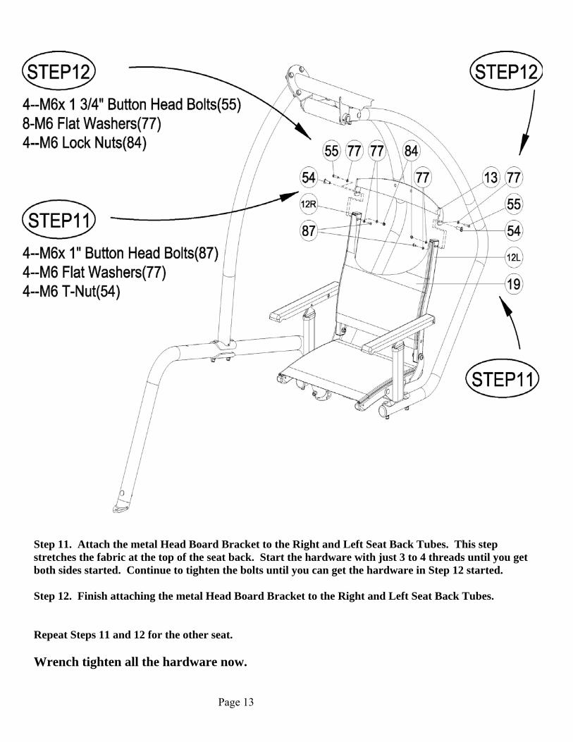
Step 11. Attach the metal Head Board Bracket to the Right and Left Seat Back Tubes. This step stretches the fabric at the top of the seat back. Start the hardware with just 3 to 4 threads until you get both sides started. Continue to tighten the bolts until you can get the hardware in Step 12 started. Step 12. Finish attaching the metal Head Board Bracket to the Right and Left Seat Back Tubes. Repeat Steps 11 and 12 for the other seat. Wrench tighten all the hardware now.
Page 13

Step 13. Attach the Head Board and Head Rest to the Head Board Bracket. Complete Step 13 for the other chair Wrench tighten all the hardware now
Page 14

Step 14. Attach the Footrest Pad to the Footrest Frame. Step 15. Attach the Retainer End Bumper to the back of the Footrest Frame. Complete Steps 14 and 15 for the other chair Wrench tighten all the hardware now but do not over tighten or damage will occur the Footrest Pad and the soft rubber Retainer End bumper.
Page 15

Step 16 and 17 Attach the table Wood Support Brackets to the Bent Legs and attach the
Wood Table to the Wood Support Brackets. Tighten the hardware now. Step 18 Place the Canopy Rods into the rod holder tubes on the Canopy Support
Assembly. They will just sit in the tubes until the Canopy is put on the swing. Note: If the canopy is too cold it will not stretch enough to get it over the last canopy rod.
Place the canopy in a warm room of the house until it warms up enough to stretch over the last canopy rod.
Step 19 The Canopy is a rectangular piece of fabric with pocketed corners. Begin by
laying the canopy on top of the Canopy Rods. Then slide one of the pocketed corners of the Canopy onto one of the Canopy rods. Continue around the Canopy until the last corner. Getting the last corner onto the Canopy Rod requires stretching the fabric by pulling the canopy fabric towards the end of the canopy rod and slightly down. Continue stretching the Canopy towards the end of the Canopy Rod until it slides into the corner pocket of the Canopy.
Page 16

Seatback Adjustment
The seat back may need adjustment to appear even on both sides when looking
down from on top or if both armrests are not catching to hold the seat back firmly in place when you lean back in the chair. Looking down from the top of the seat back if one side of the seat back is further back than the other, gently twist the Seat Back Tubes to alter the seat back’s natural position until it remains even without any force. Pressure should only be applied in the directions shown above or in their reverse directions. When properly adjusted, the ratchets on both sides of the seats will engage at each position at the same time as the seat back is reclined and raised.
Page 17
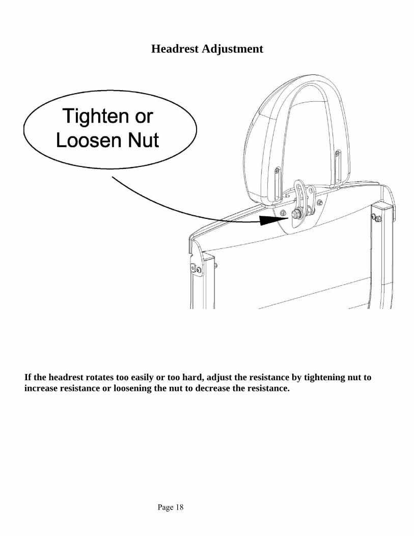
Headrest Adjustment
If the headrest rotates too easily or too hard, adjust the resistance by tightening nut to increase resistance or loosening the nut to decrease the resistance.
Page 18

Page 19
422SB Swing Weekly Maintenance Inspect and familiarize yourself with the safety warnings and other information that is posted on the decals located on the swing or in the owner’s manual. Inspect all fabric areas for tears and fabric seams for loose or damaged threads. Replace immediately if needed. Inspect all the hardware for proper tightness, Retighten if needed. Inspect the wood for weather cracking. The wood should be treated every 3 months with a wood preservative. See your local hardware retailer for suggestions for wood preservatives. Failure to protect the wood will void its warranty. The canopy is not designed for high winds. If high winds are expected remove the canopy. Failure to follow these instructions can cause damage to the canopy or canopy rods and will void the warranty. In freezing climates the canopy should be removed, folded and stored in a dry place before the first freeze or snow and until the last freeze or snow has passed. Failure to follow these instructions can cause damage to the canopy or canopy rods and will void the warranty.

Page 20
Safety Information
CAUTION!
This 422SB swing is designed for adult use only
Ensure that the 422SB swing is set up on a firm level surface. Make sure the 422SB swing has completely stopped before entering or exiting the swing. Be careful as the swing seat may shift while sitting down or getting up from the swing. The foot rest should be tucked under the seat when entering or exiting the swing. Keep all body parts within the swing seat while it is in motion. Make sure bystanders are at least 5 feet away from the swing while it is in motion. Be careful placing the swing too close to a structure as severe injury might occur if a person gets caught between the structure and the swing or damage might occur if the swing hits the structure. Be cautious swinging while children are present as they may stray into the path of the swing. Review the maintenance schedule before each use to ensure the swing is in good working order. This swing is for casual relaxation swinging only. Residential use only.

Page 21

Page 22
Sunset Swings By Health In Motion LLC
LIMITED TEN YEAR WARRANTY
Sunset Swings warrants this product to the original purchaser to be free from defects in workmanship and/or materials under normal use. If at any time a component part is defective, Sunset Swings shall repair or replace it (at Sunset Swings option) within a reasonable period of time. This warranty does not cover costs of removal, transportation or reinstallation. This warranty shall not apply if damage is caused by misuse, neglect or normal wear and tear. Starting from the original date of purchase, normal wear and tear shall be considered as the following: All failures of the rubber, fabric and wood that occur after 3 years, all failures of bearings, bushings, hardware or powder coated frame that occur after ten years. Sunset Swings sole responsibility shall be to repair or replace the component within the terms stated above. Sunset Swings shall not be liable for any loss or damage of any kind including any incidental or consequential damages resulting, directly or indirectly from any warranty expressed or implied or any other failure of this product.
WHAT IS NOT COVERED BY THIS WARRANTY Sunset Swings sole obligation under this warranty is limited to either repair or replacement of parts, subject to the additions below. This warranty neither assumes nor authorizes any person to assume obligations other than expressly covered by this warranty. NO CONSEQUETIAL DAMAGES. Sunset Swings is not responsible for economic loss; profit loss; or special, indirect, or consequential damages. WARRANTY IS NOT TRANSFERABLE. This warranty is not assignable and applies only in favor of the original purchaser/user to whom delivered. Any such assignment or transfer shall void the warranties herein made and shall void all warranties, express, implied or statutory. There are no warranties which extend beyond the description on the face hereof. ALTERATION, NEGLECT, ABUSE, MISUSE, NORMAL WEAR AND TEAR, ACCIDENT, DAMAGE DURING TRANSIT OR INSTALLATION, FIRE, FLOOD, ACTS OF GOD. Sunset Swings is not responsible for the repair or replacement of any parts that Sunset Swings determines have been subjected after the date of manufacture to alteration, neglect, abuse, misuse, normal wear and tear, accident, damage during transit or installation, fire, flood, or an ACT OF GOD. TRANSPORTATION COSTS. Sunset Swings will accept parts covered under this warranty freight collect, provided that shipment has received prior approval. Sunset Swings is not responsible for any other transportation costs, but will ship freight collect parts either repaired or replaced under these warranties. WARRANTY VALADATION AND CLAIM PROCEDURE. To validate your warranty please complete the enclosed customer warranty registration card or go to www.sunsetswings.com and complete the online warranty registration. All claims should include: model number, the serial number, proof of purchase, date of installation, and all pertinent information supporting the existence of the alleged defect. Please call for pre-approval of shipment of warranty parts.
Sunset Swings Health In Motion LLC
637 S. State College Blvd. Fullerton, CA 92831
(877) 738-1729 (714) 738-1728 fax