Embed Size (px)
Citation preview


The Project Gutenberg eBook, The Steam Engine Explained and Illustrated (Seventh Edition),by Dionysius Lardner
This eBook is for the use of anyone anywhere at no cost and with almost no restrictionswhatsoever. You may copy it, give it away or re-use it under the terms of the Project GutenbergLicense included with this eBook or online at www.gutenberg.org
Title: The Steam Engine Explained and Illustrated (Seventh Edition)
With an Account of its Invention and Progressive Improvement, and its Application toNavigation and Railways; Including also a Memoir of Watt
Author: Dionysius Lardner
Release Date: April 26, 2013 [eBook #42602]
Language: English
Character set encoding: UTF-8
***START OF THE PROJECT GUTENBERG EBOOK THE STEAM ENGINE EXPLAINEDAND ILLUSTRATED (SEVENTH EDITION)***
E-text prepared by Chris Curnow, RichardW,and the Online Distributed Proofreading Team
(http://www.pgdp.net)from page images generously made available by
Internet Archive(http://archive.org)
Note:
Images of the original pages are available through Internet Archive. Seehttps://archive.org/details/steamengineexpla00lardrich
Some characters might not display in the html version. If so, the reader should consult the iso-8859-1 (Latin-1) text file 42602-8.txt (http://www.gutenberg.org/files/42602/42602-8.txt) or42602.zip (http://www.gutenberg.org/files/42602/42602-8.zip)
The Steam Engine

Explained and Illustrated

WATT.Engraved by H. Adlard, from a Drawing by H. Corbould,
taken with the permission of James Watt, Esq.
FROM THE STATUE BY CHANTREY.
London: Taylor & Walton, Upper Gower Street.

THE
STEAM ENGINE
EXPLAINED AND ILLUSTRATED;
WITHAN ACCOUNT OF ITS INVENTION AND PROGRESSIVE
IMPROVEMENT,AND ITS APPLICATION TO
NAVIGATION AND RAILWAYS;
INCLUDING ALSO
A Memoir of Watt.
BYDIONYSIUS LARDNER, D.C.L. F.R.S.
&c. &c.
SEVENTH EDITION,ILLUSTRATED BY ENGRAVINGS ON WOOD.
LONDON:PRINTED FOR TAYLOR AND WALTON,
28. UPPER GOWER STREET.MDCCCXL.

LONDON:Printed by A. SPOT T ISWOODE,
New-Street-Square.

TOTHE RIGHT HONOURABLE
HENRY LORD BROUGHAM AND VAUX,FELLOW OF THE ROYAL SOCIETY,
ANDMEMBER OF THE NATIONAL INSTITUTE OF FRANCE,
AS A MARK OF PUBLIC RESPECTAND
A TESTIMONY OF PRIVATE REGARD,
THIS WORKINSCRIBED, BY HIS ATTACHED FRIEND,
THE AUTHOR.

ADVERTISEMENT.
The Drawings for several of the Cuts in this Volume havebeen taken, by the permission of Mr. Weale, from theadmirable Plates annexed to the last edition of Tredgold onthe Steam Engine and on Steam Navigation. Thisacknowledgment is especially due for the Illustrationswhich abound in this Volume.
London, June, 1840.
LONDON ENTRANCE TO THE BIRMINGHAM RAIL-ROAD.

CONTENTS.
CHAPTER I.
PRELIMINARY MATTER.The Steam Engine, a Subject of popular Interest 4Effects of Steam 5Great Power of Steam 7Object of this Work 9Disputes respecting the Invention 11Hero of Alexandria's Machine 13Blasco De Garay's Proposition to propel Vessels by a Machine 16Solomon De Caus 17Giovanni Branca proposes to work Mills by Steam 22Marquis of Worcester 23Mechanical Properties of Fluids 25Elastic and Inelastic Fluids 25Elasticity of Gases 28Effects of Heat 29Application of these Principles to the Engines of Hero, De Caus, and Lord
Worcester 30Sir Samuel Morland 34Denis Papin 36Atmospheric Pressure 38Weight of Air 39Pressure of Air 41Barometer 41Elastic Force of Air and Gases 42Force obtained by a Vacuum 43Common Pump 43Rarefaction by Heat 44Process of filling Thermometers 44Papin's Method of producing a Vacuum 44His Discovery of the Condensation of Steam 45Thomas Savery 47
CHAP. II.

ENGINES OF SAVERY AND NEWCOMEN.Savery's Engine 49Boilers and their Appendages 50Working Apparatus described 51Mode of Operation 52Defects of Savery's Engine 58Newcomen's Engine described by Papin 62Newcomen and Cawley obtain a Patent for Atmospheric Engine 65Accidental Discovery of Condensation by Injection 69Potter's Discovery of the Method of working the Valves 71His Contrivance improved by the Substitution of a Plug Frame 72Advantages of the Atmospheric Engine over that of Savery 72The Power of Savery's Engine restricted 73It contained no new Principle 73Its practical Superiority 73
CHAP. III.
EARLY CAREER AND DISCOVERIES OF JAMES WATT.Atmospheric Engine improved by Beighton 75Smeaton's Improvements in the Atmospheric Engine 76Brindley obtains a Patent for Improvement in 76Invents the Self-regulating Feeder 76Infancy of James Watt 77His Descent and Parentage 77Anecdotes of his Boyhood 78His early Acquirements 79Goes to London 80Returns to Glasgow 80Appointed Instrument-maker to the University 81Opens a Shop in Glasgow 81His Friends and Patrons 81Professor Robison's Remarks on Watt's personal Character 82His industrious and studious Habits 82His Attention first directed to Steam 83Experiments on High-pressure Engine 83Repairs an Atmospheric Model 84Experimental Inquiry consequent on this 84Its Results 84

Observes great Defects in the Atmospheric Engine 85His first Attempt to improve it 85His early Experiments on Steam 87Discovery by Experiment of the Expansion which Water undergoes in
Evaporation 90Discovers the latent Heat of Steam 91Informed by Dr. Black of the Theory of latent Heat 93His Improvement not due to Black 93
CHAP. IV.
EXPOSITION OF PHYSICAL PRINCIPLES.Construction of Thermometer 98Method of graduating it 99Freezing and boiling Points 99Latent Heat of Water 101Quantity of Heat necessary to convert Ice into Water, first noticed by Dr. Black
101Examination of the analogous Effects produced by the continued Application
of Heat to Water in the liquid State 102Process of Boiling 104Reconversion of Steam into Water 104Conversion of Water into Steam 105Latent Heat of Steam 107Boiling Point varies 108Different in different Places 109Inquiry whether a Diminution of Pressure will produce a corresponding Effect
on the boiling Point 112Table showing the Temperature at which Water will boil under different
Pressures of the Atmosphere 113Mechanical Force of Steam 115Facts to be observed in 117
CHAP. V.
FURTHER DISCOVERIES OF WATT.Watt finds that Condensation in the Cylinder is incompatible with a due
Economy of Fuel 119Conceives the Notion of condensing out of the Cylinder 120Discovers separate Condensation 121Invents the Air Pump 123

Substitutes Steam Pressure for Atmospheric Pressure 123Invents the Steam Case, or Jacket 124His first Experiments to realise these Inventions 125His experimental Apparatus 125His experimental Models fitted up at Delft House, in Glasgow 128Difficulties of bringing the improved Engines into Use 129Watt first employed by Roebuck as a Civil Engineer 130His Partnership with Roebuck 130His first Patent 130Experimental Engine at Kinneal 131Abstract of the Act of Parliament for the Extension of his Patent 132Description of his single-acting Steam Engine 133
CHAP. VI.
WATT'S ENGINES.Correspondence of Watt with Smeaton 145Failure of Condensation by Surface 146Improvements in Construction of Piston 147Method of Packing 148Improvements in boring the Cylinder 149Disadvantages of the new compared with the old Engines 150Greatly increased Economy of Fuel 150Economy of the Engine 151Expedients to force the new Engines into Use 151Correspondence of Boulton 153Correspondence with Smeaton 155Efficiency of Fuel in the new Engines 156Discovery of the expansive Action of Steam 157Watt states it in a Letter to Dr. Small 157Its Principle explained 158Mechanical Effects resulting from it 162Computed Effect of cutting off Steam at different Portions of the Stroke 163Produces a variable Power 163Expedients for equalising the Power 164Expansive Principle in Watt's Engines limited 165Its more extensive Application in the Cornish Engines 165
CHAP. VII.

DOUBLE-ACTING ENGINE.Common Steam 168Superheated Steam 170Laws of Dalton and Gay Lussac 171Law of Mariotte 171Relation between Temperature and Pressure of common Steam 171Effects of the Expansion of common Steam 173Mechanical Effects of Steam 173Method of equalising the expansive Force 174Hornblower's Engine 175Woolf's Engine 176Watt's Attempts to extend the Steam Engine to Manufactures 178Papin's projected Applications of the Steam Engine 178Savery's Application of the Engine to move Machinery 180Jonathan Hull's Application to Water Wheels 180Champion of Bristol applies the Atmospheric Engine to raise Water 181Stewart's Application of the Engine to Mill-work 182Wasbrough's Application of the Fly-wheel and Crank 183Reasons why Watt's single-acting Steam Engine was not adapted to produce
continuous uniform Motion of Rotation 184Watt's Second Patent 186Sun-and-Planet Wheels 187Valves of double-acting Engine 189
CHAP. VIII.
DOUBLE-ACTING ENGINE.Methods of connecting the Piston-rod and Beam in the double-acting Engine
193Rack and Sector 194Parallel Motion 195Connection of Piston-rod and Beam 195Connecting Rod and Crank 203Fly-wheel 205Throttle-valve 207Governor 209Construction and Operation of the double-acting Engine 216Eccentric 225Cocks and Valves 227

Single-clack Valves 227Double-clack Valves 228Conical Valves 228Slide Valves 229Murray's Slides 229D Valves 230Seaward's Slides 235Single Cock 238Two-way Cock 239Four-way Cock 239Pistons 242Common hemp-packed Piston 242Woolf's Piston 243Metallic Pistons 244Cartwright's Engine 245Cartwright's Piston 247Barton's Piston 248
CHAP. IX.
BOILERS AND FURNACES.Analysis of Coal 252Process of Combustion 253Heat evolved in it 254Form and Structure of Boiler 255Waggon Boiler 255Furnace 256Method of feeding it 257Combustion of Gas in Flues 260Williams's Patent for Method of consuming unburned Gases 260Construction of Grate and Ash-pit 261Magnitude of heating Surface of Boiler 262Steam-space and Water-space in Boiler 263Position of Flues 264Method of feeding Boiler 265Method of indicating the Level of Water in Boiler 266Level Gauges 266Self-regulating Feeders 267Steam Gauge 270

Barometer Gauge 272Watt's Invention of the Indicator 274Counter 278Safety-valve 279Fusible Plugs 280Self-regulating Damper 281Brunton's Self-regulating Furnace 283Gross and useful Effect of an Engine 285Power and Duty of Engines 287Horse-power of Steam Engines 289Evaporation proportional to Horse-power 290Sources of Loss of Power 292Absence of good practical Rules for Power 292Common Rules followed by Engine-makers 292Duty distinguished from Power 294Duty of Boilers 294Proportion of Stroke to Diameter of Cylinder 295Duty of Engines 296Cornish System of Inspection 297Table showing the Improvement of Cornish Engines 298Beneficial Effects of Cornish Inspection 299Successive Improvements on which the increased Duty of Engines depends,
traced by John Taylor in his "Records of Mining" 299
CHAP. X.
LIFE OF WATT.Watt's Friends and Associates at Birmingham 302His Invention of the Copying Press 302Heating Apartments and Buildings by Steam 303Watt's Machine for drying Linen 303His Share in the Discovery of the Composition of Water 303The Merit of this Discovery shared between Cavendish, Lavoisier, and Watt
305Anecdote of Watt's Activity of Mind 309His Introduction of the Use of Chlorine in Bleaching 310One of the Founders of the Pneumatic Institution at Clifton 310His first Marriage 311Death of his first Wife 311

His second Marriage 311Death of his younger Son 311Extracts from his Letters 312Character of Watt by Lord Brougham 313Extract from Sir Walter Scott's "Monastery" on the Character of Watt 314Sketch of the Life of Watt from the "Scotsman" by Lord Jeffrey 315Occupation of his old Age 318His Invention of Machine for copying Sculpture 318His last Days 318Monuments to his Memory 319Inscription by Lord Brougham on the Pedestal of the Monument in Westminster
Abbey 320
CHAP. XI.
LOCOMOTIVE ENGINES ON RAILWAYS.High-pressure Engines 322One of the earliest Forms of the Steam Engine 322Description of Leupold's Engine 323Non-condensing Engine of Messrs. Trevethick and Vivian 324Construction of a Machine for moving Carriages on Railroads 328Effects of Railway Transport 329Moral and political Consequences of 334History of the Locomotive Engine 337Construction of Locomotive Engine by Blinkensop 337Messrs. Chapman's Contrivance 337Walking Engine 337Mr. Stephenson's Engines at Killingworth 339Liverpool and Manchester Railway 342The Directors offer a Prize for the best Locomotive Engine 344Experimental Trial 344The "Rocket," "Sanspareil," and "Novelty" 344Admirable Arrangement in the Rocket 345Description of the "Sanspareil" 347Description of the "Novelty" 349The Superiority of the "Rocket" 350Method of subdividing the Flue into Tubes 353Progressive Improvement of Locomotive Engines 354Dr. Lardner's Experiments in 1832 357

Adoption of Brass Tubes 360Great Expense of Locomotive Power 361Mr. Booth's Report 362Detailed Description of the most improved Locomotive Engines 365Substitution of Brass for Copper Tubes ascribed to Mr. Dixon 370Power of Locomotive Engines 379Position of the Eccentrics 379Pressure of Steam in the Boiler 401Dr. Lardner's Experiments in 1838 406Resistance to Railway Trains 407Dr. Lardner's Experiments on the Great Western Railway 408Experiments on Resistance 409Restrictions on Gradients 410Compensating Effect of Gradients 412Experiment with the "Hecla" 412Disposition of Gradients should be uniform 415Methods of surmounting steep Inclinations 415
CHAP. XII.
LOCOMOTIVE ENGINES ON TURNPIKE ROADS.Railways and Stone Roads compared 420Gurney's Steam Carriage 423The Boiler of Gurney's Engine 423His Method of cleansing Boilers 428Convenience and Safety of Steam Carriages 432Two Methods of applying Locomotive Engines upon common Roads 434Horse Carriages compared with Steam 435Extract from Mr. Farey's Evidence before the House of Commons 435Hancock's Steam Carriage 436How it differs from that of Mr. Gurney 437Ogle's Locomotive Carriage 438Dr. Church's Steam Engine 439
CHAP. XIII.
STEAM NAVIGATION.Form and Arrangement of Marine Engines 441Arrangement of the Engine-room 446

Marine Boilers 448Effects of Sea Water in Boilers 450Remedies for them 451Blow-off Cocks 452Indicators of Saltness 453Seaward's Indicator 454His Method of blowing out 454Field's Brine Pumps 456Tubular Condensers applied by Mr. Watt 457Hall's Condensers 458Substitution of Copper for Iron Boilers 460Process of Stoking 462Watt's Expedient of attaching Felt to the Boiler Surface 463Means of economising Fuel 463Number and Arrangement of Furnaces and Flues 463Howard's Marine Engine 464Application of the expansive Principle in Marine Engines 466Recent Improvements of Messrs. Maudslay and Field 467Humphrey's Marine Engine 470Common Paddle-wheel 472Feathering Paddles 474Galloway's Patent for a Paddle-wheel with movable Paddles 476Split Paddle 478Proportion of Power to Tonnage 480Improved Efficiency of Marine Engines 482Iron Steam Vessels 483Steam Navigation to India 484
CHAP. XIV.
AMERICAN STEAM NAVIGATION.Steam Navigation first established in America 487Circumstances which led to it 488Attempts of Fitch and Rumsey to apply the single-acting Engine to the
Propulsion of Vessels 489Stevens of Hoboken commences Experiments in Steam Navigation 489Experiments of Livingstone and Fulton 489Fulton's first Boat 490The Hudson navigated by Steam 491

Extension and Improvement of River Navigation 492American Steamers 494Difference between them and European Steamers 494Steamers on the Hudson 494American Paddle-wheels 495Sea-going American Steamers 496Speed attained by American Steamers 497Lake Steamers 499The Mississippi and its Tributaries 499Steam-boats navigating it 500Their Structure and Machinery 500New Orleans Harbour 503Steam Tugs 503
APPENDIX.
On the Relation between the Temperature, Pressure, and Density of CommonSteam.
Empirical Formula of Biot, showing the Relation between the Pressure andTemperature 505
Empirical formula ofSouthern 506Tredgold 506Mellet 506De Pambour 506MM. Dulong and Arago 506
Law of the Expansion of elastic Fluids, discovered by Dalton and Gay Lussac506
Formula for the Relation between the Volumes and Temperatures 507Law of Mariotte 507Table of Pressures, Temperatures, Volumes, and Mechanical Effects of Steam
509Empirical Formulæ for the Relation between the Volume of Water and that of
the Steam produced by its Evaporation under given Pressures 511Formula of Navier 511Modified by De Pambour 511
On the Expansive Action of Steam.Mechanical Effect produced during a given Extent of Expansion 511Mechanical Effect produced during Evaporation and subsequent Expansion
512
Application to double-acting Engines 513Formula for Pressure of Steam in Cylinders 514Formula for total Mechanical Effect per Minute of Steam when cut off at any
proposed Part of the Stroke 514Formulæ exhibiting the Relation between the Resistance of the Load, the
Resistances of the Engine, the Evaporation, the Speed of the Piston, and theMagnitude of the Cylinder 515
Formulæ showing the Relation between the Power of the Engine, theEvaporation, and the useful Load 516
Formulæ for the useful Effect and the Duty 517Estimates of the several Sources of Resistances 518Tables to facilitate the Computation of the Effects of Expansive Engines 519Table of the Areas of Pistons 520EXAMPLES of the Application of these Formulæ 521
INDEX.

VIADUCT, NEAR WATFORD, BIRMINGHAM RAIL-ROAD.

THE
STEAM ENGINE.
HERO OF ALEXANDRIA.


CHAPTER I.
[Pg003]
TOC INX
THE STEAM ENGINE, A SUBJECT OF POPULAR INTEREST.—THE OBJECT OF THIS WORK.—DISPUTESRESPECTING THE INVENTION.—HERO.—DE GARAY.—DE CAUS.—BRANCA.—MARQUIS OFWORCESTER.—PHYSICAL PRINCIPLES.—ELASTIC AND INELASTIC FLUIDS.—THEIR PROPERTIES.—APPLICATION OF THESE PRINCIPLES TO THE ENGINES OF HERO, DE CAUS, AND LORD WORCESTER.—SIR SAMUEL MORLAND.—PAPIN.—ATMOSPHERIC PRESSURE.—THE WEIGHT OF AIR.—LESS ATGREATER HEIGHTS.—BAROMETER.—PRESSURE OF AIR.—ELASTIC FORCE OF AIR AND GASES.—FORCEPRODUCED BY A VACUUM.—COMMON PUMP.—RAREFACTION BY HEAT.—PAPIN'S METHODS OFPRODUCING A VACUUM.—HIS DISCOVERY OF THE CONDENSATION OF STEAM.—SAVERY.
(1.) That the history of the invention of a piece of mechanism, and the description of its structure,operation, and [Pg004] uses, should be capable of being rendered the subject matter of a volume,destined not alone for the instruction of engineers or machinists, but for the information andamusement of the public in general, is a statement which at no very remote period would have beendeemed extravagant and incredible.
Advanced as we are in the art of rendering knowledge popular, and cultivated as the public tasteis in the appreciation of the expedients by which science ministers to the uses of life, there is stillperhaps but one machine of which such a proposition can be truly predicated: it is needless to saythat that machine is the STEAM ENGINE. There are many circumstances attending this extraordinarypiece of mechanism which impart to it an interest so universally felt. Whether we regard thedetails of its structure and operation, the physical principles which it calls into play, and thebeautiful contrivances by which these physical principles are rendered available;—or, passingover these means, we direct our attention to the ends which they attain, we are equally filled withastonishment and admiration. The history of the steam engine offers to our notice a series ofcontrivances which, for exquisite and refined ingenuity, stand without any parallel in the annals ofmechanical science. These admirable inventions, unlike other results of scientific inquiry, havealso this peculiarity, that, to understand their excellence and to perceive their beauty, no previousor subsidiary knowledge is necessary, save what may be imparted with facility and clearness inthe progress of the explanation and development of the machine itself. A simple and clearexposition, divested of needless technicalities and aided by well-selected diagrams, is all that isnecessary to render the construction and operation of the steam engine, in all its forms, intelligibleto persons of plain understanding and moderate information.
But if the contrivances by which this vast power is brought to bear on the arts and manufactures,be rendered attractive by their great mechanical beauty, how much more imposing will the subjectbecome when the effects which the steam engine has produced upon the well-being of the humanrace are considered. It has penetrated the crust of the earth, and drawn from beneath it boundlesstreasures [Pg005] of mineral wealth, which, without its aid, would have been rendered inaccessible;it has drawn up, in measureless quantity, the fuel on which its own life and activity depend; it hasrelieved men from their most slavish toils, and reduced labour in a great degree to light and easysuperintendence. To enumerate its present effects, would be to count almost every comfort andevery luxury of life. It has increased the sum of human happiness, not only by calling newpleasures into existence, but by so cheapening former enjoyments as to render them attainable by

those who before could never have hoped to share them: the surface of the land, and the face of thewaters, are traversed with equal facility by its power; and by thus stimulating and facilitating theintercourse of nation with nation, and the commerce of people with people, it has knit togetherremote countries by bonds of amity not likely to be broken. Streams of knowledge and informationare kept flowing between distant centres of population, those more advanced diffusing civilisationand improvement among those that are more backward. The press itself, to which mankind owes inso large a degree the rapidity of their improvement in modern times, has had its power andinfluence increased in a manifold ratio by its union with the steam engine. It is thus that literature ischeapened, and, by being cheapened, diffused; it is thus that Reason has taken the place of Force,and the pen has superseded the sword; it is thus that war has almost ceased upon the earth, and thatthe differences which inevitably arise between people and people are for the most part adjusted bypeaceful negotiation.
Deep as the interest must be with which the steam engine will be regarded in every civilisedcountry, it presents peculiar claims upon the attention of the people of Great Britain. Its inventionand progressive improvement are the work of our own time and our own country; it has beenproduced and matured almost within the last century, and is the exclusive offspring of Britishgenius, fostered and sustained by British enterprise and British capital.
The steam engine is a mechanical contrivance, by which coal, wood, or other fuel is renderedcapable of executing any [Pg006] kind of labour. COALS are by it made to spin, weave, dye, print anddress silks, cottons, woollens, and other cloths; to make paper, and print books upon it when made;to convert corn into flour; to express oil from the olive, and wine from the grape; to draw up metalfrom the bowels of the earth; to pound and smelt it, to melt and mould it; to forge it; to roll it, andto fashion it into every desirable form; to transport these manifold products of its own labour to thedoors of those for whose convenience they are produced; to carry persons and goods over thewaters of rivers, lakes, seas, and oceans, in opposition alike to the natural difficulties of wind andwater; to carry the wind-bound ship out of port; to place her on the open deep ready to commenceher voyage; to throw its arms around the ship of war, and place her side by side with the enemy; totransport over the surface of the deep persons and information, from town to town, and fromcountry to country, with a speed as much exceeding that of the ordinary wind, as the ordinary windexceeds that of a common pedestrian.
Such are the virtues, such the powers, which the steam engine has conferred upon COALS. Themeans of calling these powers into activity are supplied by a substance which nature has happilyprovided in unbounded quantity in every part of the earth; and though it has no price, it hasinestimable value: this substance is WATER.
A pint of water may be evaporated by two ounces of coals. In its evaporation it swells into twohundred and sixteen gallons of steam, with a mechanical force sufficient to raise a weight of thirty-seven tons a foot high. The steam thus produced has a pressure equal to that of commonatmospheric air; and by allowing it to expand, by virtue of its elasticity, a further mechanical forcemay be obtained, at least equal in amount to the former. A pint of water, therefore, and two ouncesof common coal, are thus rendered capable of doing as much work as is equivalent to seventy-fourtons raised a foot high.
The circumstances under which the steam engine is worked on a railway are not favourable tothe economy of fuel. Nevertheless a pound of coke burned in a locomotive engine [Pg007] will

evaporate about five pints of water. In their evaporation they will exert a mechanical forcesufficient to draw two tons weight on the railway a distance of one mile in two minutes. Fourhorses working in a stage-coach on a common road are necessary to draw the same weight thesame distance in six minutes.
A train of coaches weighing about eighty tons, and transporting two hundred and fortypassengers with their luggage, has been taken from Liverpool to Birmingham, and back fromBirmingham to Liverpool, the trip each way taking about four hours and a quarter, stoppagesincluded. The distance between these places by the railway is ninety-five miles. This doublejourney of one hundred and ninety miles is effected by the mechanical force produced in thecombustion of four tons of coke, the value of which is about five pounds. To carry the same numberof passengers daily between the same places by stage-coaches on a common road, would requiretwenty coaches and an establishment of three thousand eight hundred horses, with which thejourney in each direction would be performed in about twelve hours, stoppages included.
The circumference of the earth measures twenty-five thousand miles; and if it were begirt withan iron railway, such a train as above described, carrying two hundred and forty passengers,would be drawn round it by the combustion of about thirty tons of coke, and the circuit would beaccomplished in five weeks.
In the drainage of the Cornish mines the economy of fuel is much attended to, and coals are theremade to do more work than elsewhere. A bushel of coals usually raises forty thousand tons ofwater a foot high; but it has on some occasions raised sixty thousand tons the same height. Let ustake its labour at fifty thousand tons raised one foot high. A horse worked in a fast stage-coachpulls against an average resistance of about a quarter of a hundred weight. Against this he is ableto work at the usual speed through about eight miles daily: his work is therefore equivalent to onethousand tons raised one foot. A bushel of coals consequently, as used in Cornwall, performs asmuch labour as a day's work of one hundred such horses. [Pg008]
The great pyramid of Egypt stands upon a base measuring seven hundred feet each way, and isfive hundred feet high, its weight being twelve thousand seven hundred and sixty millions ofpounds. Herodotus states, that in constructing it one hundred thousand men were constantlyemployed for twenty years. The materials of this pyramid would be raised from the ground to theirpresent position by the combustion of about four hundred and eighty tons of coals.
The Menai Bridge consists of about two thousand tons of iron, and its height above the level ofthe water is one hundred and twenty feet. Its mass might be lifted from the level of the water to itspresent position by the combustion of four bushels of coal.
The enormous consumption of coals produced by the application of the steam engine in the artsand manufactures, as well as to railways and navigation, has of late years excited the fears of manyas to the possibility of the exhaustion of our coal-mines. Such apprehensions are, however,altogether groundless. If the present consumption of coal be estimated at sixteen millions of tonsannually, it is demonstrable that the coal-fields of this country would not be exhausted for manycenturies.
But in speculations like these, the probable, if not certain progress of improvement anddiscovery ought not be overlooked; and we may safely pronounce that, long before such a periodof time shall have rolled away, other and more powerful mechanical agents will supersede the useof coal. Philosophy already directs her finger at sources of inexhaustible power in the phenomena
of electricity and magnetism. The alternate decomposition and recomposition of water, bymagnetism and electricity, has too close an analogy to the alternate processes of vaporisation andcondensation, not to occur at once to every mind: the development of the gases from solid matterby the operation of the chemical affinities, and their subsequent condensation into the liquid form,has already been essayed as a source of power. In a word, the general state of physical science atthe present moment, the vigour, activity, and sagacity with which researches in it are prosecuted inevery civilised [Pg009] country, the increasing consideration in which scientific men are held, and thepersonal honours and rewards which begin to be conferred upon them, all justify the expectationthat we are on the eve of mechanical discoveries still greater than any which have yet appeared;and that the steam engine itself, with the gigantic powers conferred upon it by the immortal Watt,will dwindle into insignificance in comparison with the energies of nature which are still to berevealed; and that the day will come when that machine, which is now extending the blessings ofcivilisation to the most remote skirts of the globe, will cease to have existence except in the pageof history.
(2.) The object of the present volume will be to deliver, in an easy and familiar style, anhistorical view of the invention of the steam engine, and an exposition of its structure andoperation in the various forms in which it is now used, and of its most important applications in thearts of life, especially in transport by land and water. It is hoped that the details of these subjectsmay be rendered easily intelligible to all persons of ordinary information, whether urged by thatnatural and laudable spirit of inquiry awakened by contemplating effects on the material and socialcondition of our species, so rapid and so memorable as those which have followed the inventionof the steam engine, and by the pleasure which results from the perception of the numerousinstances of successful contrivances and beautiful applications of science to art which it unfolds,—or impelled by the exigencies of trade or profession to acquire an acquaintance with a machineon which, more than any other, the prosperity of our commercial and manufacturing interestsdepends. It will be our aim to afford to the former class all the information which they can require;and, if this work be not as comprehensive in its scope, and as minute in its details, as some of thelatter may wish, it will at least serve as an easy and convenient introduction to other works morevoluminous, costly, and detailed, but less elementary in their matter, and less familiar in their style.
In explaining the different forms of steam engine which have been proposed in the course of theprogressive improvement [Pg010] of that machine from its early rude and imperfect state to its presentcomparatively perfect form, it will be necessary to advert to various physical phenomena andmechanical principles, which, however obvious to those who are conversant with matters ofscience, must necessarily be at least imperfectly known by the great majority of our readers. Torefer for information on such topics to other works on Mechanics and general Physics, would bewith most readers ineffectual, and with all unsatisfactory. In former editions of the present work,we consigned these necessary general principles of physics and mechanics to a preliminarychapter; but it appears, on the whole, more convenient not to remove the exposition of the principlefrom the place where its application is required. We shall therefore pause as we proceed, wherethese difficulties occur, to give such explanation and illustration as may seem best suited to renderthem intelligible and interesting to the unscientific reader.
The history of the arts and manufactures affords no example of any invention the credit for whichhas been claimed by so many different nations and individuals as that of the steam engine. Theadvocates of the competitors for this honour have urged their pretensions, and pressed their claims,

with a zeal which has occasionally outstripped the bounds of discretion, and the contest has notunfrequently been tinged with prejudices, national and personal, and characterised by a degree ofasperity altogether unworthy of so noble a cause, and beneath the dignity of science.
"When a question is clearly proposed, it is already half resolved." Let us see whether a carefulattention to this maxim will aid us in the investigation of the origin of the steam engine. The sourceof the power of that machine is found in the following natural phenomena.
First. When fire is applied to water, the liquid swells into vapour, and in undergoing this changeexerts, as has been already stated, a considerable amount of mechanical force. This force may,by proper means, be rendered applicable to any purpose for which labour or power is needful.Second. The vapour so produced is endowed with the property of elasticity, in virtue of which itis capable of [Pg011] swelling or expanding into increased dimensions, exerting, as it expands, aforce, the energy of which is gradually diminished as the dimensions of the vapour areincreased. This mechanical force is likewise capable of being applied to any useful purpose forwhich labour or power is necessary.
Third. This vapour is capable, by proper means, of being reconverted into water; and when soreconverted, it shrinks into its original dimensions, deserting the large space which it occupiedas vapour, and leaving that space a vacuum. It is known in physics, that when a vacuum isproduced, surrounding bodies have a tendency to rush into it with a definite amount of force.Consequently any agent which produces a vacuum, becomes a source of a considerable amountof mechanical power. By its reconversion into water, therefore, steam again becomes amechanical agent.
Such are the natural phenomena in which are found the original sources of all steam power. Insome forms of steam engine one of these is used, and in some another, and in some the applicationof all of them is combined; but in no existing form of steam engine whatever is there any othersource of mechanical power.
Neither these nor any other natural forces can be applied immediately to any useful purpose.The interposition of mechanism is indispensable; on the invention and contrivance of thatmechanism depends altogether the useful application of these natural forces.
The world owes the steam engine then partly to discovery, and partly to invention.
He that discovered the fact, that mechanical force was produced in the conversion of water intosteam, must be justly held to be a sharer in the merit of the steam engine, even though he shouldnever have practically applied his discovery. The like may be said of him who first discovered thesource of the mechanical power arising from the expansion of steam.
The discoverer of the fact, that steam being reconverted into water greatly contracted itsdimensions, and thereby produced a vacuum, is likewise entitled to a share of the credit. [Pg012]
The mechanism by which these natural forces have been rendered so universally available as amoving power, is very various and complicated, and cannot be traced to one inventor. "If awatchmaker," says M. Arago, "well instructed in the history of his art, were required to give acategorical answer to the question, Who has invented watches? he would remain mute; but thequestion would be divested of much of its difficulty if he were required separately to declare whodiscovered the use of the main spring, the different forms of escapement, or the balance wheel." So

it is with the steam engine. It is a combination of a great variety of contrivances, distinct from eachother, which are the production of several inventors. If, however, one name more than the rest beentitled to special notice; if he is entitled to the chief credit of the invention who by the powers ofhis mechanical genius has imparted to the steam engine that form, and conferred upon it thosequalities, on which mainly depends its present extensive utility, and by which it has become anagent of transcendant power, spreading its beneficial effects throughout every part of the civilisedglobe, then the universal voice will, as it were by acclamation, award the honour to oneindividual, whose pre-eminent genius places him far above all other competitors, and from theapplication of whose mental energies to this machine may be dated those grand effects whichrender it a topic of interest to all for whom the progress of civilisation has any attractions. Beforethe era rendered memorable by the discoveries of JAMES WATT , the steam engine, which has sincebecome an object of such universal interest, was a machine of extremely limited power, inferior inimportance and usefulness to most other mechanical agents used as prime movers; but, from thatepoch, it is scarcely necessary here to state, that it became a subject not of British interest only, butone having an important connection with the progress of the human race.
HERO OF ALEXANDRIA, 120 B. C.
Fig. 1.
(3.) The discovery of the fact, that a mechanical force is produced when water is evaporated bythe application of heat, [Pg013] must be considered as the first capital step in the invention of thesteam engine. It is recorded in a work entitled Spiritalia seu Pneumatica, that Hero of Alexandriacontrived a machine, 120 years before the Christian era, which was moved by the mechanicalforce of the vapour of water. The principle of this machine admits of easy explanation: When afluid issues from any vessel in which it is confined, that vessel suffers a force equal to that withwhich the fluid escapes from it, and in the opposite direction. If water issues from an orifice, apressure is produced behind the orifice corresponding to the force with which the water escapes.If a man discharge a gun, the gases produced by the explosion of the powder issue with a certainforce from the muzzle, and his shoulder is driven backwards by the recoil with a correspondingforce. If the muzzle, instead of being presented forwards, were turned at right angles to the lengthof the gun, then, as the gases of explosion would escape sideways, the recoil would likewise takeplace sideways, and the shooter, instead of being driven backward, would be made to spin roundas a dancer pirouettes. This was the principle of Hero's steam engine. A small globe or ball wasplaced on pivots at A and B (fig. 1.), on which it was capable of revolving: steam was suppliedthrough one of these pivots from one of the tubes D C E F, which communicated with the boiler. This

steam filled the globe A I B K, and also the arms I H and K G. A lateral orifice, represented at G, nearthe end of these arms, allowed the steam to escape in a jet, and the reaction, producing a recoil,had a tendency to drive the arm round. A small orifice at H, on the other side of the tube, produceda like effect. In the same manner, any convenient number of arms might be provided, surroundingthe globe and communicating with its interior like the spokes of a wheel. Thus these arms, havinglateral orifices for the escape of the steam, all placed so that the recoil may [Pg014] tend to turn theglobe in the same direction, a rotatory motion might be communicated to any machinery which itwas desired to move.
After having been allowed to slumber for nearly two thousand years, this machine has recentlybeen revived, and engines constructed similar to it are now working in these countries. In theproper place we shall describe Avery's Rotatory Engine, which it will be seen is, not only in itsprinciple, but almost in its details, the machine of HERO OF ALEXANDRIA.
Although the elastic force of steam was not reduced to numerical measure by the ancients, norbrought under control, nor applied to any useful purpose, yet it appears to have been recognised invague and general terms. Aristotle, Seneca, and other ancient writers, accounted for earthquakesby the sudden conversion of water into steam within the earth. This change, according to them, waseffected by subterranean heat. Such tremendous effects being ascribed to steam, it can scarcely bedoubted that the Greeks and Romans were acquainted with the fact, that water in passing intovapour exercises considerable mechanical power. They were aware that the earthquakes, whichthey ascribed to this cause, exerted forces sufficiently powerful to extend the natural limits of theocean; to overturn from their foundations the most massive monuments of human labour; to raiseislands in the midst of seas; and to heave up the surface of the land of level continents so as to formlofty mountains.
Such notions, however, resulted not as consequences of any exact or scientific principles, butfrom vague analogies derived from effects which could not fail to have been manifested in the arts,such as those which commonly occurred in the process of casting in metal the splendid statueswhich adorned the temples, gardens, and public places of Rome and Athens. The artisan wasliable to the same accidents to which modern founders are exposed, produced by the casualpresence of a little water in the mould into which the molten metal is poured. Under suchcircumstances, the sudden formation of steam of an extreme pressure produces, as is well known,explosions attended with destructive effects. The Grecian [Pg015] and Roman artisans were subjectto such accidents; and the philosopher, generalising such a fact, would arrive at a solution of thegrander class of phenomena of earthquakes and volcanoes.
Before natural phenomena are rendered subservient to purposes of utility, they are often made tominister to the objects of superstition. The power of steam is not an exception to this rule. It isrecorded in the Chronicles, that upon the banks of the Weser the ancient Teutonic gods sometimesmarked their displeasure by a sort of thunderbolt, which was immediately succeeded by a cloudthat filled the temple. An image of the god Busterich, which was found in some excavations,clearly explains the manner in which this prodigy was accomplished by the priests. The head of themetal god was hollow, and contained within it a pot of water: the mouth, and another hole, abovethe forehead, were stopped by wooden plugs; a small stove, adroitly placed in a cavity of the headunder the pot, contained charcoal, which, being lighted, gradually heated the liquid contained in thehead. The vapour produced from the water, having acquired sufficient pressure, forced out thewooden plugs with a loud report, and they were immediately followed by two jets of steam, which

formed a dense cloud round the god, and concealed him from his astonished worshippers.[1]
Among other amusing anecdotes showing the knowledge which the ancients had of themechanical force of steam, it is related that Anthemius, the architect of Saint Sophia, occupied ahouse next door to that of Zeno, between whom and Anthemius there existed a feud. To annoy hisneighbour, Anthemius placed on the ground floor of his own house several close digesters, orboilers, containing water. A flexible tube proceeded from the top of each of these, which wasconducted through a hole made in the wall between the houses, and which communicated with thespace under the floors of the rooms in the house of Zeno. When Anthemius desired to annoy hisneighbour, he lighted fires under his boilers, and the steam produced by them rushed in suchquantity and with [Pg016] such force under Zeno's floors, that they were made to heave with all theusual symptoms of an earthquake.[2]
BLASCO DE GARAY, A. D. 1543.
(4.) In the year 1826, M. de Navarrete published, in Zach's Astronomical Correspondence, acommunication from Thomas Gonzales, Director of the royal archives of Simancas, giving anaccount of an experiment reported to have been made in the year 1543, in which a vessel waspropelled by a machine having the appearance of a steam engine.
Blasco de Garay, a sea captain, proposed in that year to the Emperor Charles V. to propelvessels by a machine which he had invented, even in time of calm, without oars or sails.Notwithstanding the apparent improbability attending this project, the Emperor ordered theexperiment to be made in the port of Barcelona, and the 17th of June, 1543, was the day appointedfor its trial. The commissioners appointed by Charles V. to attend and witness the experiment wereDon Henry of Toledo, Don Pedro of Cardona, the treasurer Ravago, the vice chancellor andintendant of Catalonia, and others. The vessel on which the experiment was made was the Trinity,200 tons burthen, which had just discharged a cargo of corn at Barcelona. Garay concealed thenature of his machinery, even from the commissioners. All that could be discovered during the trialwas, that it consisted of a large boiler containing water, and that wheels were attached to each sideof the vessel, by the revolution of which it was propelled. The commissioners having witnessedthe experiment, made a report to the king, approving generally of the invention, particularly onaccount of the ease and promptitude with which the vessel could be put about by it.
The treasurer Ravago, who was himself hostile to the project, reported that the machine wascapable of propelling a vessel at the rate of two leagues in three hours; but the othercommissioners stated that it made a league an hour at the least, and that it put the vessel about asspeedily as would be accomplished with a galley worked according to the common [Pg017] method.Ravago reported that the machinery was too complicated and expensive, and that it was subject tothe danger of the boiler bursting.
After the experiment was made, Garay took away all the machinery, leaving nothing but theframing of wood in the arsenals of Barcelona.
Notwithstanding the opposition of Ravago, the invention was approved, and the inventor waspromoted and received a pecuniary reward, besides having all his expenses paid.
From the circumstance of the nature of the machinery having been concealed, it is impossible tosay in what this machine consisted; but as a boiler was used, it is probable, though not certain, thatsteam was the agent. There have been various machines proposed, of which a furnace and boiler

form a part, and in which the agency of steam is not used. The machine of Amontons furnishes anexample of this. It is most probable that the contrivance of Garay was identical with that of Hero.The low state of the arts in Spain in the sixteenth century would be incompatible with theconstruction of any machine requiring great precision of execution. But the simplicity of Hero'scontrivance would have rendered its construction and operation quite practicable. As to the claimsto the invention of the steam engine advanced by the advocates of De Garay, founded on the abovedocument, a refutation is supplied by the admission, that though he was rewarded and promoted bythe government of the day, in consequence of the experiment, and although the great usefulness ofthe contrivance in towing ships out of port, &c., was admitted, yet it does not appear that a secondexperiment was ever tried, much less that the machine was ever brought into practical use.
SOLOMON DE CAUS, 1615.
(5.) Solomon De Caus was engineer and architect to Louis XIII., king of France, before the year1612. In that year he entered the service of the Elector Palatine, who married the daughter of KingJames I., with whom he came to England. He was there employed by the Prince of Wales inornamenting the gardens of his house at Richmond. [Pg018] During his sojourn in England hecomposed and published at London, in the same year, a Treatise on Perspective. This person wasthe author of a work entitled, "Les Raisons des Forces Mouvantes, avec diverses Machines tantutiles que plaisantes," which was apparently composed at Heidelburg, but published atFranckfort, in 1615. The same work was subsequently republished in Paris in 1623.
The treatise commences with definitions of what were then considered the four elements: earth,air, fire, and water. Air is defined to be a cold, dry, and light element, capable of compression, bywhich it may be rendered very violent. He says, "The violence will be great when water exhales inair by means of fire, and that the said air is enclosed: as, for example, take a ball of copper of oneor two feet diameter, and one inch thick, which being filled with water by a small hole, whichshall be strongly stopped with a peg, so that neither air nor water can escape, it is certain that ifwe put the said ball upon a great fire, so that it will become very hot, that it will cause acompression so violent, that the ball will burst in pieces, with a noise like a petard."
The effect which is here described is due to the combined pressure of the heated air contained inthe ball and the high pressure steam raised from the water, but much more to the latter than to theformer. It is evident, however, from the language of De Caus, that he ascribes the force entirely tothe air, and seems to consider that the force of the air proceeded from the water which exhaled init.
The first theorem is, "that the parts of the elements mix together for a time, and then each returnsto its place" (the elements here referred to being apparently air and water). Upon this subject thefollowing is an example: "Take a round vessel of copper, soldered close on every side, and with atube, whereof one end approaches nearly to the bottom of the vessel, and the other end, whichprojects on the outside of the vessel, has a stop-cock; there is also a hole in the top of the vessel,with a plug to stop it. If this vessel will contain three pots of water, then pour in one pot of water,and place the vessel on the fire about three or four minutes, leaving the hole open; then take thevessel off the [Pg019] fire, and a little after pour out the water at the hole, and it will be found that apart of the said water has been evaporated by the heat of the fire. Then pour in one pot of water asbefore, and stop up the hole and the cock, and put the vessel on the fire for the same time as before;then take it off, and let it cool of itself, without opening the plug, and after it is quite cold pour outthe water, and it will be found exactly the same quantity as was put in. Thus we see that the water

which was evaporated (the first time that the vessel was put on the fire) is returned into water thesecond time when that vapour has been shut up in the vessel, and cooled of itself."
In the description of these experiments, the processes of evaporation and condensation areobscurely indicated; but there is no intimation that the author possessed any knowledge of theelastic force of steam. His theorem is, that the parts of the element water mix for a time with theparts of the element air; that fire causes this mixture, and that on removing the fire, and dissipatingthe heat, then the parts of the water mixed with air return to their proper place, forming again partof the water. There is no indication of a change of property of the water in passing into vapour. Itis difficult to conceive, if De Caus had been aware that the vapour of water possessed the sameviolent force which he distinctly and in terms ascribes to air, or if he had been aware that in effectthe vapour of the water produced by the fire was a fluid, possessing exactly the same mechanicalqualities, and producing the same mechanical effects as air, that he would not have expressedhimself clearly on the subject.
He proceeds to give another demonstration that heat will cause the particles of water to mixwith those of air.
"After having put the measure of water into the vessel, and shut the vent-hole, and opened thecock, put the vessel on the fire, and put the pot under the cock; then the water of the vessel, raisingitself by the heat of the fire, will run out through the cock; but about one sixth or one eighth part ofthe water will not run out, because the violence of the vapour which causes the water to riseproceeds from the [Pg020] said water; which vapour goes out through the cock after the water withgreat violence. There is also another example in quicksilver, or mercury, which is a fluid mineral,but being heated by fire, exhales in vapour, and mixes with the air for a time; but after the saidvapour is cooled, it returns to its first nature of quicksilver. The vapour of water is much lighter,and therefore it rises higher," &c. &c.
In this second demonstration there appears to be some obscure indication of the force of steamin the words "because of the violence of the vapour which causes the water to rise," &c.
The fifth theorem is the following:—
"Water will mount by the help of fire higher than its level," which is explained and proved inthe following terms:—
Fig. 2.

"The third method of raising water is by the aid of fire. On this principle may be constructedvarious machines: I shall here describe one. Let a ball of copper marked A; well soldered in everypart, to which is attached a tube and stop-cock marked D, by which water may be introduced; andalso another tube marked B C, which will be soldered into the top of the ball, and the lower end Cof which shall descend nearly to the bottom of the ball without touching it. Let the said ball befilled with water through the tube D, then shutting the stop-cock D, and opening the stop-cock in thevertical tube B C, let the ball be placed upon a fire the heat acting upon the said ball will cause thewater to rise in the tube B C."
In the apparatus as here described, the space enclosed in the boiler above the surface of thewater is filled with air. By the action of the fire, two effects are produced: first, the air enclosedabove the water, being heated, acquires increased elasticity, and presses with a correspondingforce on the surface of the water. By this means a column of water will be driven up the tube A B atsuch a height as will balance the elasticity of the heated air confined in the boiler; but besides [Pg021]
this the water contained in the boiler being heated, will produce steam, which being mixed with aircontained in the boiler, will likewise press with its proper elasticity on the surface of the water,and will combine with the air in raising a column of water in the tube A B. In the above descriptionof the machine, the force which raises the water in the tube A B is ascribed to the fire, no mentionbeing made of the water, or of the vapour or steam produced from it having any agency in raisingthe water in the tube A B.
Antecedently to the date of this invention, the effect of heat in increasing the elastic force of airwas known, and so far as the above description goes, the whole operation might be ascribed to theair by a person having no knowledge whatever of the elasticity of steam. M. Arago, however, who,on the grounds of this passage in the work of De Caus, claims for him a share of the honour of theinvention of the steam engine, contends that the agency of steam in this apparatus was perfectlyknown to De Caus, although no mention is made of steam in the above description, because in thesecond demonstration above quoted he uses the words, "the violence of the vapour which causesthe water to rise proceeds from the said water; which vapour goes out from the cock after thewater with great violence." By these words M. Arago considers that De Caus expresses the qualityof elasticity proper to the vapour, and that the context justifies the inference, that to this elasticityhe ascribed the elevation of the water in the tube C B.
There appears to be some uncertainty attending the birthplace of De Caus. In the BiographieUniverselle he is said to have been born and to have died in Normandy. M. Arago assigns Dieppe,or its neighbourhood, as his birthplace.
There was another engineer and architect, Isaac De Caus, a native of Dieppe, who published awork in folio, entitled "Nouvelle Invention de Lever l'Eau plus haut que sa Source, avec quelqueMachines mouvantes, par le Moyen de l'Eau, et un Discours de la Conduite d'Icelle." Thisvolume is without a date, but from the nature of its contents it would appear to have been publishedbefore the work of Solomon De Caus already cited. The drawings and machines described in both[Pg022] are exactly the same; but the definitions and theorems quoted above on raising water by fireare not given in the work of Isaac. It seems, therefore, that Solomon De Caus re-published, withadditions, the work of Isaac De Caus. From the same birthplace being assigned to both theseauthors, as well as from the similarity of their pursuits, it is likely they were members of the samefamily, and from their christian names they were probably Jews.

The work cited above, was dedicated to Louis XIII., and in the dedication Solomon De Causcalls himself the subject of that monarch; and in the privilege prefixed to the work he is designated,"Our well-beloved Solomon De Caus, master engineer, being at present in the service of our dearand well-beloved cousin, the Prince Elector Palatine, has made known to us," &c.—"we, desiringto gratify the said De Caus, he being our subject," &c.
It is therefore certain, whatever may have been the birthplace of De Caus, that he was at least asubject of France. The circumstance of his work being written in French, though published beyondthe Rhine, is also an argument in favour of his being a native of that country.
GIOVANNI BRANCA, 1629.
(6.) Giovanni Branca of Loretto in Italy, an engineer and architect, proposed to work mills ofdifferent kinds by steam issuing from a large æolopile, and blowing against the vanes of a wheel.Branca was the author of many ingenious mechanical inventions, a collection of which hededicated to M. Cenci, the governor of Loretto. These were published in a work printed at Romein 1629. It is a thin quarto, entitled "Le Machine volume nuovo, et di molto artificio da fareeffetti maravigliosi tanto Spiritali quanto di Animale Operatione, arichito di bellissime figure.Del Sig. Giovanni Branca, Cittadino Romano. In Roma, 1629." The work contains sixty-threeengravings, accompanied by descriptions in Italian and Latin. Branca's steam engine, representedin the twenty-fifth plate, consists of a wheel furnished with flat vanes upon its rim, like the boardsof a paddle wheel. The steam is produced in a close vessel, and made to issue with violence fromthe extremity [Pg023] of a pipe directed against the vanes, and causes the wheel to revolve. Thismotion being imparted by the usual mechanical contrivances, any machinery may be impelled by it.Different useful applications of this power are contained in the work, viz. pestles and mortars forpounding materials to make gunpowder, and rolling stones for grinding the same; machines forraising water by buckets, for sawing timbers, for driving piles, &c. &c.
This method of applying the force of steam has no analogy to any application of steam in modernengines.
EDWARD SOMERSET, MARQUIS OF WORCESTER, 1663.
(7.) Of all the names which figure in the early annals of steam, by far the most remarkable is thatof the Marquis of Worcester, who has left a description of a machine in a work, entitled "TheScantling of One Hundred Inventions," which has been generally in this country considered asgiving him a right to the honour of having been the inventor of the steam engine.
Lord Worcester having been engaged on the side of the Royalists in the civil wars of therevolution, lost his fortune, and went to Ireland, where he was imprisoned. He escaped fromthence, and reached France; from that country he ventured to London, as a secret agent of CharlesII., but was detected, and imprisoned in the Tower, where he remained until the restoration, whenhe was set at liberty. Tradition has connected the invention of the steam engine with the followinganecdote:—One day, during his imprisonment, Lord Worcester observed the lid of the pot in whichhis dinner was being cooked, suddenly forced upwards by the vapour of the water which wasboiling in it. Reflecting on this, it occurred to him that the same force which raised the cover of thepot might be rendered, when properly applied, a useful and convenient moving power. After herecovered his liberty, he accordingly proceeded to carry into effect this conception. Thecontrivance to which he was ultimately led is described in the following terms in the sixty-eighthinvention, in the work above named:—

"I have invented an admirable and forcible way to drive [Pg024] up water by fire; not by drawingor sucking it upwards, for that must be, as the philosopher terms it, infra sphœrum activitatis,which is but at such a distance. But this way hath no bounder if the vessels be strong enough. For Ihave taken a piece of whole cannon whereof the end was burst, and filled it three quarters full ofwater, stopping and screwing up the broken end, as also the touch-hole, and making a constant fireunder it; within twenty-four hours, it burst and made a great crack. So that, having a way to makemy vessels so that they are strengthened by the force within them, and the one to fill after the other,I have seen the water run like a constant fountain stream forty feet high. One vessel of waterrarefied by fire driveth up forty of cold water, and a man that tends the work has but to turn twococks; that one vessel of water being consumed, another begins to force and refill with cold water,and so successively; the fire being tended and kept constant, which the self-same person maylikewise abundantly perform in the interim between the necessity of turning the said cocks."
Since the date of the publication of the "Century of Inventions" was the year 1663, theexperiments here mentioned must have been made before that year. The description of the machinehere given, as well as others in the same work, was intended by the author, not to convey aknowledge of the nature of the mechanism which he used, but only to express the effects produced,and to indicate the physical principle on which they depended. It should also be observed, that anair of mystery was thrown by Worcester over the accounts of all the machines which he described;and therefore any obscurity in the above description ought not to be regarded as an evidenceagainst his claim to the discovery of the mechanical agency of steam, so far as that agency isindicated by the effects said by him to be produced. The above account is, however, sufficientlydistinct and explicit to enable any one possessing a knowledge of the mechanical qualities of steamto perceive the general nature of the machine described. To render this machine, and that of DeCaus, previously described, intelligible to those who are not familiar with physical science, wemust here explain some general principles on which their agency depends. [Pg025]
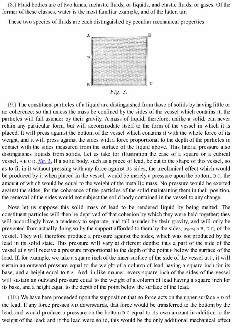
(8.) Fluid bodies are of two kinds, inelastic fluids, or liquids, and elastic fluids, or gases. Of theformer of these classes, water is the most familiar example, and of the latter, air.
These two species of fluids are each distinguished by peculiar mechanical properties.
Fig. 3.
(9.) The constituent particles of a liquid are distinguished from those of solids by having little orno coherence; so that unless the mass be confined by the sides of the vessel which contains it, theparticles will fall asunder by their gravity. A mass of liquid, therefore, unlike a solid, can neverretain any particular form, but will accommodate itself to the form of the vessel in which it isplaced. It will press against the bottom of the vessel which contains it with the whole force of itsweight, and it will press against the sides with a force proportional to the depth of the particles incontact with the sides measured from the surface of the liquid above. This lateral pressure alsodistinguishes liquids from solids. Let us take for illustration the case of a square or a cubicalvessel, A B C D, fig. 3. If a solid body, such as a piece of lead, be cut to the shape of this vessel, soas to fit in it without pressing with any force against its sides, the mechanical effect which wouldbe produced by it when placed in the vessel, would be merely a pressure upon the bottom, B C, theamount of which would be equal to the weight of the metallic mass. No pressure would be exertedagainst the sides; for the coherence of the particles of the solid maintaining them in their position,the removal of the sides would not subject the solid body contained in the vessel to any change.
Now let us suppose this solid mass of lead to be rendered liquid by being melted. Theconstituent particles will then be deprived of that cohesion by which they were held together; theywill accordingly have a tendency to separate, and fall asunder by their gravity, and will only beprevented from actually doing so by the support afforded to them by the sides, [Pg026] A B, D C, of thevessel. They will therefore produce a pressure against the sides, which was not produced by thelead in its solid state. This pressure will vary at different depths: thus a part of the side of thevessel at P will receive a pressure proportional to the depth of the point P below the surface of thelead. If, for example, we take a square inch of the inner surface of the side of the vessel at P, it willsustain an outward pressure equal to the weight of a column of lead having a square inch for itsbase, and a height equal to P A. And, in like manner, every square inch of the sides of the vesselwill sustain an outward pressure equal to the weight of a column of lead having a square inch forits base, and a height equal to the depth of the point below the surface of the lead.
(10.) We have here proceeded upon the supposition that no force acts on the upper surface A D ofthe lead. If any force presses A D downwards, that force would be transferred to the bottom by thelead, and would produce a pressure on the bottom B C equal to its own amount in addition to theweight of the lead; and if the lead were solid, this would be the only additional mechanical effect

which such a force acting on the surface A D of the lead would produce. But if, on the other hand,the lead were liquified, then the force now adverted to, acting on the surface A D, would not onlyproduce a pressure on the bottom B C, equal to its own amount in addition to the weight of the lead,but it would also produce a pressure against every part of the sides of the vessel, equal to thatwhich it would produce upon an equal magnitude of the surface A D.
Thus if we suppose any mechanical cause producing a pressure on the surface A D amounting toten pounds on each square inch, the effect which would be produced, if the lead were solid, wouldbe an additional pressure on the base B C amounting to ten pounds per square inch. But if the leadwere liquid, besides this pressure on each square inch of the base B C, there would likewise be apressure of ten pounds on every square inch of the sides of the vessel.
All that has been here stated with respect to a square or a cubical vessel will be equallyapplicable to a vessel of any other form. [Pg027]
(11.) The second class of fluids are distinguished from liquids by the particles not merely beingdestitute of cohesion, but having a tendency directly the reverse, to repel each other, and flyasunder with more or less force. Thus if a vessel, such as that represented in fig. 3., were filledwith a fluid of this kind, being open at the top, and not being restrained by any pressure incumbentupon it, the particles of the fluid would not rest in the vessel by their gravity, as those of the liquidwould do; but they would, by their mutual repulsion, fly asunder, and rise out of the vessel, assmoke is seen to rise from a chimney, or steam from the spout of a kettle. Let us suppose, then, thatthe vessel in which an elastic fluid is contained is closed on every side by solid surfaces. In fact,let us imagine that the square or cubical vessel represented in fig. 3. is closed by a square lid atthe top A D, having contained in it an elastic fluid, such as atmospheric air.
If such a cover, or lid, had been placed upon a liquid, the cover would sustain no pressure fromthe fluid, nor would any mechanical effect be produced, save those already described in the caseof the open vessel; but when the fluid contained in the vessel is elastic, as is the case with air, thenthe elasticity (by which name is expressed the tendency of the particles of the fluid to fly asunder)will produce peculiar mechanical effects, which have no existence whatever in the case of aliquid.
It is true that, supposing the fluid to be air or any other gas or vapour, a pressure will beproduced upon the bottom B C of the vessel equivalent to the weight of such fluid, and lateralpressures will be produced on the different points of the sides by the weight of that part of the fluidwhich is above these points; but gases and vapours are bodies of such extreme levity, that theseeffects due to their weight are neglected in practice.
Putting, then, the weight of the air contained in the vessel out of the question, let us consider theeffect of its elasticity. If the vessel, as already described, be supposed to contain atmospheric airin its ordinary state, the tendency of the constituent particles to fly asunder will be such as toproduce on every square inch of the inner surface of the vessel [Pg028] a pressure amounting tofifteen pounds; this pressure being, as already stated, quite independent of the weight of the air. Infact, this pressure would continue to exist if the air contained in the vessel actually ceased to haveweight by being removed from the neighbourhood of the earth, which is the cause of its gravity.
(12.) Different gases are endowed with different degrees of elasticity, and the same gas mayhave its elasticity increased or diminished, either by varying the space within which it is confined,

or by altering the temperature to which it is exposed.
If the space within which an elastic fluid is enclosed be enlarged, its elasticity is found todiminish in the same proportion. Thus if the air contained in the vessel A B C D (fig. 3.) be allowedto pass into a vessel of twice the magnitude, the elasticity of the particles will cause them to repeleach other, so that the same quantity of air shall diffuse itself throughout the larger vessel, assumingdouble its former bulk. Under such circumstances, the pressure which it would exert upon the sidesof the larger vessel would be only half that which it had exerted on the sides of the smaller vessel.If, on the other hand, it were forced into a vessel of half the magnitude of A B C D, as it might be,then its elasticity would be double, and it would press on the inner surface of that vessel withtwice the force with which it pressed on that of the vessel A B C D.
This power of swelling and contracting its dimensions according to the dimensions of the vesselin which it is confined, or to the force compressing it, is a quality which results immediately fromelasticity, and is consequently one which is peculiar to the gases or elastic fluids, and does not atall appertain to liquids. If the liquid contained in the vessel A B C D were transferred to a vessel oftwice the magnitude, it would only occupy half the capacity of that vessel, and it could not by anymeans be transferred, as we have supposed the air or gas to be, to a vessel of half the dimensions,since it is inelastic and incompressible.
(13.) The elasticity of gases is likewise varied by varying the temperature to which they areexposed; thus, in general, [Pg029] if air or any other gas be augmented in temperature, it will likewisebe increased in elasticity; and if, on the other hand, it be diminished in temperature, it will belikewise diminished in its elastic force. The more heated, therefore, any air or gas confined in avessel becomes, the greater will be the force with which it will press on the inner surface of thatvessel, and tend to burst it.
(14.) The same body may, by the agency of heat, be made to pass successively through thedifferent states of solid, liquid, and gas, or vapour. The most familiar and obvious example ofthese successive transitions is presented by water. Exposed to a certain temperature, water canonly exist as a solid; as the temperature is increased, the ice, or solid water, is liquefied; and bythe continued application of heat, this water again undergoes a change, and assumes the form, andacquires the mechanical qualities, of air or gas: in such a state it is called STEAM.
This is a common property of all liquids. If they be exposed for a sufficient length of time to asufficient degree of heat, they will always be converted into elastic fluids. These are usuallydistinguished from air and other permanent gases, which never are known to exist in the liquidform, by the term vapour, by which, therefore, must be understood an elastic fluid which atcommon temperatures exists in the liquid or solid state; by steam is expressed the vapour of water;and by gases, those elastic fluids which like air are never known—at least, under ordinarycircumstances—to exist in any other but the elastic form.
(15.) When a liquid is caused, by the application of heat, to take the form of an elastic fluid, oris evaporated, besides acquiring the property of elasticity, it always undergoes a considerablechange of bulk. The amount of this change is different with different liquids, and even with thesame liquid it varies with the circumstances under which the change is produced.
(16.) When water is evaporated under ordinary circumstances,—that is, when exposed to noother external pressure than that of the atmosphere,—it increases its volume about seventeen-

hundred-fold. Thus a cubic inch of liquid [Pg030] water would form about seventeen hundred cubicinches of common steam. If, however, the water be confined by a greater pressure than thatproduced by the common atmosphere, then the increase of volume which takes place in itsevaporation would be less in proportion.
These important physical circumstances are now only indicated in a general way. As weproceed with our account of the invention and improvement of the steam engine, they will bedeveloped more fully and accurately.
(17.) After duly considering what has been just explained, no difficulty will be found incomprehending the principles on which the first rude attempts at the mechanical application ofsteam already stated depend. In the apparatus ascribed to Hero of Alexandria, the elasticity of thevapour contained in the arms of the revolving ball causes that vapour to issue from the lateralorifices in the arms, such as that of G, fig. 1. As these orifices, however, are exposed to thecommon atmosphere pressing inwards with a force, the mean amount of which has been stated tobe about fifteen pounds per square inch, it follows that the steam cannot escape from these orificesuntil its pressure or elasticity exceeds this amount, and that when it does, the force with which itwill so escape will be the excess of its elasticity above that of the atmosphere; and it is thereaction produced by this difference of pressure, causing the arms to recoil, which will givemotion to the machine.
In the case of the apparatus of De Caus (5.), the heat of the fire acting on the vessel D C (fig. 2.)will raise the temperature of the water contained in it, and also of the air confined within it abovethe surface of that water. This air, as it is increased in temperature, will also increase in elasticity;it will therefore press on the surface of the water with increased force, and will gradually forcethe water upwards in the tube; and this effect would continue until all the water in the vessel wouldbe forced up the tube.
But at the same time that the heat acting on the vessel increases the temperature of the air abovethe water, it also produces a partial evaporation of the water, so that more or less steam is mixedwith the air in the vessel above the surface [Pg031] of the water; and this steam possessing elasticity,unites with the air in pressing on the surface of the water, and in raising it in the tube.

Figs. 4, 5, and 6.
Let us now revert to the brief account of the engine of the Marquis of Worcester, described in"The Century of Inventions." We collect from that description that the vessel in which the waterwas evaporated was separate from those which contained the water to be elevated; also that therewere two vessels of the like description, the contents of which were alternately elevated by thepressure of the "water rarefied by the fire;" in other words by steam; and that the water was raisedin an uninterrupted stream, by the management of two cocks communicating with these vessels andwith the boiler. The following is such an apparatus as would answer this description. Let E (fig.4.) be the vessel containing the water to be evaporated, placed over a proper furnace A; let S be apipe to allow the steam produced from the boiling water in E to pass into the vessels where itsmechanical action is required. Let R represent a cock or regulator, having in it a curved passage,leading from S to the tube T, when the lever or handle L is in the position represented by the cut; butleading to the tube T′, when the lever L is turned one quarter of a revolution to the right, asrepresented in fig. 5. By the shifting of this lever, therefore, the steam pipe S may be made tocommunicate alternately with the tubes T and T′. The tubes T and T′ are carried respectively to twovessels V and V′, which are filled with the water required to be raised. In these [Pg032] vessels tubesenter at C and C′, descending nearly to the bottom: these tubes have valves at B and B′, openingupwards, by which water will be allowed to pass into the vertical tube F, but which will not allowit to return downwards, the valves B and B′ being then closed by the weight of the water abovethem.
Let G G′ be a pipe entering the sides of the vessels V and V′, for the purpose of filling them withthe water to be raised: let K be a cock having a curved passage similar to the cock R, and leadingto a tube by which water is supplied from the reservoir or other source from which the water to beraised is drawn. When the cock K is placed as represented in fig. 4., the water from the reservoirwill flow through the curved passage in the cock K into the tube G′, and thence into the vessel V′;
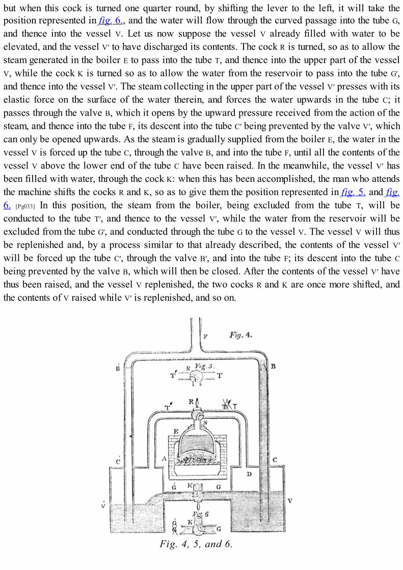
but when this cock is turned one quarter round, by shifting the lever to the left, it will take theposition represented in fig. 6., and the water will flow through the curved passage into the tube G,and thence into the vessel V. Let us now suppose the vessel V already filled with water to beelevated, and the vessel V′ to have discharged its contents. The cock R is turned, so as to allow thesteam generated in the boiler E to pass into the tube T, and thence into the upper part of the vesselV, while the cock K is turned so as to allow the water from the reservoir to pass into the tube G′,and thence into the vessel V′. The steam collecting in the upper part of the vessel V′ presses with itselastic force on the surface of the water therein, and forces the water upwards in the tube C; itpasses through the valve B, which it opens by the upward pressure received from the action of thesteam, and thence into the tube F, its descent into the tube C′ being prevented by the valve V′, whichcan only be opened upwards. As the steam is gradually supplied from the boiler E, the water in thevessel V is forced up the tube C, through the valve B, and into the tube F, until all the contents of thevessel V above the lower end of the tube C have been raised. In the meanwhile, the vessel V′ hasbeen filled with water, through the cock K: when this has been accomplished, the man who attendsthe machine shifts the cocks R and K, so as to give them the position represented in fig. 5. and fig.6. [Pg033] In this position, the steam from the boiler, being excluded from the tube T, will beconducted to the tube T′, and thence to the vessel V′, while the water from the reservoir will beexcluded from the tube G′, and conducted through the tube G to the vessel V. The vessel V will thusbe replenished and, by a process similar to that already described, the contents of the vessel V′
will be forced up the tube C′, through the valve B′, and into the tube F; its descent into the tube C
being prevented by the valve B, which will then be closed. After the contents of the vessel V′ havethus been raised, and the vessel V replenished, the two cocks R and K are once more shifted, andthe contents of V raised while V′ is replenished, and so on.
Fig. 4, 5, and 6.

If, having comprehended the apparatus here described, the reader refers to the description of theMarquis of Worcester's machine, he will find that all the conditions therein laid down are fulfilledby it. One vessel (E) of "water rarefied by fire" may by such means "drive up forty (or more) ofcold water; and the man that tends the work has but to turn two cocks, that one vessel (V) of waterbeing consumed, another (V′) begins to force and refill with cold water, and so on successively, thefire being tended and kept constant; which the self-same person may likewise abundantly perform,in the interim between the necessity of turning the said cocks."
On comparing this with the contrivance previously suggested by De Caus, it will be observed,that even if De Caus [Pg034] knew the physical agent by which the water was driven upwards in theapparatus described by him, still it was only a method of causing a vessel of boiling water toempty itself; and before a repetition of the process could be made, the vessel should be refilled,and again boiled. In the contrivance of Lord Worcester, on the other hand, the agency of the steamwas employed in the same manner as it is in the steam engines of the present day, being generatedin one vessel, and used for mechanical purposes in another. Nor must this distinction be regardedas trifling or insignificant, because on it depends the whole practicability of using steam as amechanical agent. Had its action been confined to the vessel in which it was produced, it nevercould have been employed for any useful purpose.
Although many of the projects contained in Lord Worcester's work were in the highest degreeextravagant and absurd, yet the engine above described is far from being the only practicable anduseful invention proposed in it. On the contrary, many of his inventions have been reproduced, andsome brought into general use since his time. Among these may be mentioned, stenography,telegraphs, floating baths, speaking statues, carriages from which horses can be disengaged ifunruly, combination locks, secret escutcheons for locks, candle moulds, the rasping mill, the gravelengine, &c.
SIR SAMUEL MORLAND, 1683.
(18.) Sir Samuel Morland was the son of a baronet of the same name, who had received his titleat the restoration for some services to the royalist party, performed by him during the wars of theCommonwealth. He appears to have devoted much attention to mechanics, in which he attainedsome celebrity. He was the reputed inventor of several ingenious contrivances, such as the drumcapstan for ships, the plunger pump, &c. He also investigated various questions in acoustics, andamong others, the determination of the best form for the speaking-trumpet.
In 1680, Sir Samuel Morland was appointed Master [Pg035] of the Works to Charles II., and in thefollowing year was sent to France, to execute some waterworks for Louis XIV. In 1683, while inFrance, he wrote in the French language, a work entitled "Elevation des Eaux par toute sorte deMachines, reduite à la Mesure, au Poids et à la Balance. Presentée à sa Majesté trèsChrestienne, par le Chevalier Morland, Gentilhomme Ordinaire de la Chambre Privée, etMaistre des Méchaniques du Roi de la Grande Brétagne, 1683." This book is preserved inmanuscript in the Harleian Collection in the British Museum. It is written on vellum, and consistsof only thirty-eight pages. It contains tables of measures and weights, theorems for the calculationof the volumes of cylinders, the weights of columns of water, the thickness of lead for pipes, and isconcluded by a chapter on steam, consisting of four pages, of which the following is a translation:—
"The principles of the new force of fire invented by Chevalier Morland in 1682, and

presented to His Most Christian Majesty in 1683:—
"'Water being converted into vapour by the force of fire, these vapours shortly require a greaterspace (about 2000 times) than the water before occupied, and sooner than be constantly confinedwould split a piece of cannon. But being duly regulated according to the rules of statics, and byscience reduced to measure, weight, and balance, then they bear their load peaceably (like goodhorses), and thus become of great use to mankind, particularly for raising water, according to thefollowing table, which shows the number of pounds that may be raised 1800 times per hour to aheight of six inches by cylinders half filled with water, as well as the different diameters anddepths of the said cylinders.'"
There is nothing in the description here given which can indicate the form of the machine bywhich Morland proposed to render the force of steam a useful mover. It is, however, remarkable,that at this early period, before experiments had been made on the expansion which waterundergoes in evaporation, he should have given so near an approximation to [Pg036] the actualamount of that expansion. It is scarcely supposable that such an estimate could be obtained by himotherwise than by experiment.
The work containing the above description was not printed; but a work bearing nearly the sametitle, containing, however, no mention of the force of steam, was published by him in Paris in theyear 1685. In this he describes various experiments made by him at St. Germains on the weight ofthe water of the Seine, and gives weights of the columns of water, the contents of cylinders, &c.
Soon after the publication of this work, Morland returned to England, and resided near the courttill his death. The celebrated John Evelyn mentioned having paid a visit to him at his house atHammersmith, in 1695, when he had become aged and blind, but was still remarkable for hismechanical ingenuity. "On the 25th of October," says Evelyn, "the Archbishop and myself went toHammersmith to visit Sir Samuel Morland, who was entirely blind; a very mortifying sight. Heshowed us his invention of writing (short-hand), which was very ingenious; also his woodenkalendar, which instructed him all by feeling; and other pretty and useful inventions of mills,pumps, &c.; and the pump he had erected, that serves water to his garden and to passengers, withan inscription, and brings from a filthy part of the Thames near it a most perfect and pure water."[3]
He died at Hammersmith, in January 1696; and before his death, as a penance for his past life,was guilty of the eccentricity of burying in the ground six feet deep a great collection of musicwhich he possessed.[4]
DENIS PAPIN, 1688.
(19.) Denis Papin, a native of Blois in France, and professor of mathematics at Marbourg, is thename which stands next recorded in the progressive invention of the steam engine. To thisphilosopher is due the discovery of one of the qualities of steam, to the proper management ofwhich is owing much of the efficacy of the modern steam engine. [Pg037]
Papin was born at Blois in France. He devoted his youth to the study of medicine, in which hetook a degree at Paris. The revocation of the Edict of Nantes having driven him into exile, he wentto England, where the celebrated Boyle associated him in several of his experiments with the air-pump, and caused him to be elected a fellow of the Royal Society in 1681. Having been invited toGermany by the Landgrave of Hesse, he discharged during several years the duties of professor ofmathematics at the university of Marbourg, where he died in 1710. Notwithstanding his

discoveries respecting the agency of steam, he never received any mark of distinction in his owncountry. The truth is, the importance and value of these investigations were not apparent until longafterwards.
This philosopher conceived the idea of producing a moving power by means of a pistonworking in a cylinder, in the manner which we shall now briefly explain.
Fig. 7.
Let A B (fig. 7.) be a cylinder open at the top, and let a piston P be fitted into it, so as to move init air tight. At the bottom of the cylinder suppose an opening provided, which can be closed atpleasure, by a stop-cock, or otherwise, so that the communication may be opened and closed atwill between the interior of the cylinder and the external air. This stop-cock being opened, let thepiston be drawn upwards till it reach the top of the cylinder. Let the stop-cock at the bottom be thenremoved, and imagine that some means can be supplied by which the air within the cylinder can besuddenly annihilated. The piston, now at the top, will have above it the pressure of the atmosphere;and having no air below, it will be resisted in its descent by no force save that arising from itsfriction with the cylinder. If, then, the force of the air above the piston be greater than theresistance arising from this friction, the piston will descend with the excess of this force, and willcontinue so to descend until it reach the bottom of the cylinder. Having attained that position, let us[Pg038] suppose the stop-cock in the bottom opened, so as to allow the external air to pass freelybelow the piston. The piston may now be drawn to the top of the cylinder again, offering noresistance save that of its weight, and its friction with the cylinder. Having reached the top of thecylinder once more, let the stop-cock be closed, and the air included within the cylinder once moreannihilated. A second descent of the piston will take place, with the same force as before, and inlike manner the process may be continued indefinitely.
Now, if it should appear that means could be provided suddenly and repeatedly to annihilate theair within the cylinder, and that the pressure of the atmosphere above the piston should exert aforce compared with which the weight of the piston and its friction are trifling, it is evident that amoving power would be obtained which would be capable, by proper mechanism, of beingapplied to any useful purpose, but which would more especially be applicable to the working ofpumps, the motion of which corresponds with that which has been just ascribed to the piston in thecylinder. Such were the first ideas of Papin. But in order to enable those who are not conversantwith physical science fully to appreciate their importance, it will be necessary here to explainsome of the mechanical properties of atmospheric air.

(20.) The atmosphere is the thin, transparent, colourless, and therefore invisible, fluid in whichwe live and move, which by respiration sustains animal life, and is otherwise connected withvarious important functions of organised matter. This fluid is so light and attenuated, that it might atfirst be doubted whether it be really a body at all; and, indeed, the name expressing incorporealbeings, spirit, is a word in its origin signifying air.[5] The air, however, is light only as comparedwith other material substances, which exist in a more condensed state: it possesses the quality ofweight as absolutely as the most solid and massive bodies in nature, and to render this qualitymanifest, it is only necessary to submit a sufficient quantity of air to any of the usual tests ofgravitation. [Pg039]
A direct demonstration of this may be given by the following experiment:—On the mouth of aflask let a stop-cock be fastened so as to be air-tight. The interior of the flask may then be put intofree communication with the external air, or that communication may be cut off at pleasure, byopening or closing the stop-cock. If a syringe be applied to the mouth of the flask, the stop-cockbeing open a part of the air contained in it may be drawn out. After this, the stop-cock beingclosed, and the syringe detached, let the flask be placed in the dish of a good balance, andaccurately counterpoised by weights in the other dish. This counterpoise will then represent theweight of the flask, and of the air which has remained in it. If the stop-cock be now opened, airwill immediately rush in, and replace that which the syringe had withdrawn from the flask; andimmediately the dish of the balance containing the flask will sink by the effect of the weight of theair thus admitted into the flask.
If the weight of quantity of air so small as to be capable of being withdrawn by a syringe froman ordinary flask be thus of sensible amount, it may be easily imagined that the vast mass ofatmosphere extending from the surface of the earth upwards, to a height not ascertained withprecision, but certainly not being less than thirty miles, must be very considerable. Such a force,pressing as it must constantly do, upon the surfaces of all bodies, whether solid or fluid, andresisting and modifying their movements, would play an important part in all mechanicalphenomena; and it is, therefore, not sufficient merely to have recognised its existence, but it is mostneedful to measure its amount with that degree of certainty and precision, which will enable us toestimate its effects on those phenomena which we shall have to investigate.
(21.) The amount of the pressure of the atmosphere on each square inch of horizontal surface onwhich it rests, is obviously the weight of the column of air extending from that square inch ofsurface upwards to the top of the atmosphere. This force is measured by the following means:—
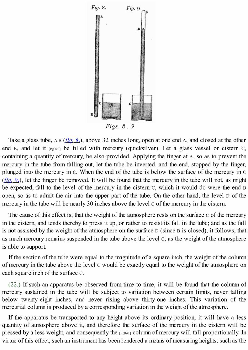
Figs. 8., 9.
Take a glass tube, A B (fig. 8.), above 32 inches long, open at one end A, and closed at the otherend B, and let it [Pg040] be filled with mercury (quicksilver). Let a glass vessel or cistern C,containing a quantity of mercury, be also provided. Applying the finger at A, so as to prevent themercury in the tube from falling out, let the tube be inverted, and the end, stopped by the finger,plunged into the mercury in C. When the end of the tube is below the surface of the mercury in C
(fig. 9.), let the finger be removed. It will be found that the mercury in the tube will not, as mightbe expected, fall to the level of the mercury in the cistern C, which it would do were the end B
open, so as to admit the air into the upper part of the tube. On the other hand, the level D of themercury in the tube will be nearly 30 inches above the level C of the mercury in the cistern.
The cause of this effect is, that the weight of the atmosphere rests on the surface C of the mercuryin the cistern, and tends thereby to press it up, or rather to resist its fall in the tube; and as the fallis not assisted by the weight of the atmosphere on the surface D (since B is closed), it follows, thatas much mercury remains suspended in the tube above the level C, as the weight of the atmosphereis able to support.
If the section of the tube were equal to the magnitude of a square inch, the weight of the columnof mercury in the tube above the level C would be exactly equal to the weight of the atmosphere oneach square inch of the surface C.
(22.) If such an apparatus be observed from time to time, it will be found that the column ofmercury sustained in the tube will be subject to variation between certain limits, never fallingbelow twenty-eight inches, and never rising above thirty-one inches. This variation of themercurial column is produced by a corresponding variation in the weight of the atmosphere.
If the apparatus be transported to any height above its ordinary position, it will have a lessquantity of atmosphere above it, and therefore the surface of the mercury in the cistern will bepressed by a less weight, and consequently the [Pg041] column of mercury will fall proportionally. Invirtue of this effect, such an instrument has been rendered a means of measuring heights, such as the

heights of mountains, the ascents of balloons, &c. &c.
(23.) If a proper scale be attached to the tube containing the mercurial column, showing theabsolute height of the column sustained at any time, and indicating its changes of height, theinstrument becomes a BAROMETER.
Two cubic inches of mercury weigh very nearly one pound avoirdupois.[6] Hence, when thebarometric column measures thirty inches, the weight of the atmosphere resting on each square inchof surface is about fifteen pounds.
(24.) It is an established property of fluids, that they press equally in all directions; and air, likeevery other fluid, participates in this quality. Hence, it follows, that when the downward pressureor weight of the atmosphere is fifteen pounds on the square inch, the lateral, upward, and obliquepressures are of the same amount. But, independently of the general principle, it may besatisfactory to give experimental proof of this.
Fig. 10.
Let four glass tubes, A, B, C, D (fig. 10.), be constructed of sufficient length, closed at one end, A,B, C, D, and open at the other. Let the open ends of three of them be bent, as represented in the tubesB, C, D. Being previously filled with mercury, let them all be gently inverted, so as to have theirclosed ends up, as here represented. It will be found that the mercury will be sustained in all, andthat the difference of the levels in all will be the same.[7] Thus, the mercury is sustained in A by theupward pressure of the atmosphere; in B, by its horizontal or lateral pressure; in C, by itsdownward pressure; [Pg042] and in D, by its oblique pressure: and, as the difference of the levels isthe same in all, these pressures are exactly equal.
(25.) The same arrangement by which the pressure of the atmosphere is measured by a mercurialcolumn of equivalent weight, also supplies the means of measuring the pressure or elasticity ofatmospheric air, or any other gas or vapour, whether in a more or less compressed or rarefied
state; and as instruments constructed on this principle are of considerable use in steam engines, weshall take this occasion to explain their principle and application.
In the experiments described in (21), the space D B in the top of the barometer-tube, from whichthe mercury descended, is a vacuum. If, however, it were occupied by a quantity of air in ararefied state, or any other gas or vapour, such gas or vapour would press on the surface of themercury at D, with a force determined by its elasticity. In that case, the atmospheric pressure actingon the surface of the mercury C in the cistern, would be balanced by the combined forces of theweight of the mercurial column sustained in the tube, and the elasticity of the gas or vapour in theupper part of it. Now if we know the actual amount of the atmospheric pressure,—that is to say, theheight of the column of mercury which it would be capable of sustaining,—we should then be ableto determine the pressure of the rarefied air in the space C D.
For example, let us suppose that the barometric column, when B D (fig. 9.) is a vacuum,measures thirty inches: the atmospheric pressure, therefore, would be equal to the weight of acolumn of mercury of that height. Let us suppose that the elasticity of the gas or vapour occupyingthe upper part of the tube D B causes the column to fall to the height of twenty-six inches: it isevident, then, that the pressure of the air in the top of the tube would be equal to the weight of acolumn of mercury of four inches. In fine, to determine the pressure of the rarefied gas or vapour inthe top of the tube, it is only necessary to observe the difference between the height of the columnof mercury actually sustained in the tube, and the column sustained at the same time and [Pg043] placein a common barometer: the difference of the two will be the column of mercury whose weightwill represent the pressure of the vapour or gas in the top of the tube.
(26.) Whenever the air contained in any vessel or other enclosed space has by any means had itspressure reduced so as to be rendered less than that of the external air, the external air will have atendency to rush into such vessel or enclosed space with a force proportionate to the excess of thepressure of such external air over that of the air within; and if any communication be openedbetween the interior of such vessel or enclosed space, and the external air, the latter will rush inuntil an equilibrium be established between the pressures within and without. It is evident that theforce thus obtained by diminishing the pressure of air within a vessel may be applied to anymechanical purpose.
It is by such means that water is raised in an ordinary pump. A portion of the air containedbetween the piston of the pump and the surface of the water below, is withdrawn by the action ofthe piston, and the pressure of the air remaining under the piston is thereby diminished. Thesuperior pressure of the atmosphere upon the external surface of the water in the well then forcesup a column of water in the pump-barrel, and this is continued as the air is more and more rarefiedby the action of the piston. By whatever means, therefore, the air can be wholly or partiallywithdrawn from any space, a mechanical power will be thereby developed, proportional in itsamount and efficacy to the quantity of air so withdrawn. If, however, such air be withdrawn by anymechanical process, such as by a syringe, by a common pump, or by an air-pump, the quantity offorce expended in withdrawing it is always equivalent to the amount of mechanical powerobtained by the vacuum or partial vacuum so produced. Indeed the power expended is greater thanthe power so obtained, inasmuch as the friction, leakage, &c. of the exhausting apparatus must beallowed for.

(27.) There are, however, various other means by which air may be partially expelled from avessel besides the direct application of mechanical force. Thus if heat be applied to [Pg044] thevessel, the air, as has been already explained, will acquire increased elasticity, and will rush fromthe vessel with a force proportionate to the excess of its elasticity above that of the external air,and this process may be continued by increasing the heat to which the vessel is exposed, until avery considerable portion of the air has been expelled. If the orifice by which the air has escapedbe then closed, and the vessel be allowed to cool, the air within, by having its temperature reducedto that of the external air, will lose all the elasticity which it had gained from the heat, and will bein the same condition as if an equivalent quantity of air had been withdrawn by any mechanicalagent. The external air, therefore, will have a tendency to rush in with a force corresponding to thedifference of pressures.
The process of filling thermometers with mercury shows one use of producing a high degree ofrarefaction by heat. To construct the instrument it is necessary to fill the bulb and a part of the tubewith mercury; but the bore of the tube is so small that the mercury cannot be introduced by anyordinary means. It is therefore held over flame until heated to a high temperature. The air within itgradually increasing in pressure as its temperature is raised, is forced through the small bore of thetube, until the pressure of the air within becomes no more than equal to the pressure of the externalatmosphere; this air being so rarefied that quantity in the bulb bears a very small proportion to itscontents at common temperatures. The mouth of the tube is then plunged into mercury, and as thebulb cools, the air within it loses its elasticity, and the superior pressure upon the external surfaceforces the mercury into the tube. This continues until the air remaining within the bulb has been socontracted, that its pressure combined with the weight of the mercury, shall balance theatmospheric pressure. The tube is then reversed, and the air which remained rises in a bubble tothe surface, and escapes.
(28.) Let us now return to the proceedings of Papin. How great a power would result from sucha machine as he conceived, will be apparent, if it be considered that the unresisted atmosphereexercises a pressure of about fifteen pounds on [Pg045] each square inch of surface exposed to it, andthat if the piston in the cylinder imagined by Papin, had a diameter of only one foot, its superficialmagnitude would be about 114 square inches. The pressure of the atmosphere upon it, therefore,would be 114 times fifteen pounds, or 1710 pounds. Papin first proposed to produce the vacuumunder the piston by means of common air pumps, worked by a water-wheel; and by such means heconceived that the power of a river, stream, or waterfall might be conveyed by pipes to a distance.While he was in England, in 1687, he laid his contrivance before the Royal Society of London, butwas met by objections and difficulties, the nature of which he does not explain.
It is, however, apparent, from what has been already explained, that such a method ofproceeding would amount to a mere transfer of power, and would not, properly speaking, be itselfa moving force: the moving power would, in reality, be the force of the water by which the water-wheel would be driven; and the air-pumps, tubes, together with the piston and cylinder, would bemerely means of conveying the power of the water-wheel to the objects to be moved, or themachinery to be driven. Papin states, that, long before this, he had attempted to expel the air fromhis cylinder by means of gunpowder; but, notwithstanding all the precautions which he could take,there always remained a considerable quantity; so much, indeed, as to deprive the vacuum of morethan half its proper force. At length he adopted an expedient for the production of a vacuum whichforms a most important step in the progressive invention of the steam engine, and which gives to

Papin's name a high place in the history of that machine. This method is explained in the followingparagraph of a work published by Papin in 1695, at Cassel, entitled "Recueil de diverses Piècestouchant quelques nouvelles Machines", p. 53.
"I have endeavoured," says he, "to attain this end (viz. the production of a vacuum in thecylinder) in another way. As water has the property of elasticity, when converted into steam byheat, and afterwards of being so completely recondensed by cold, that there does not remain theleast [Pg046] appearance of this elasticity, I have thought that it would not be difficult to workmachines in which, by means of a moderate heat and at a small cost, water might produce thatperfect vacuum which has vainly been sought by means of gunpowder."
This remarkable passage is given in the work just cited, as an extract from the "Leipsic Acts," ofAugust, 1690.
Let us pause here to explain more fully this important discovery.
(29.) We have explained that, in its conversion into vapour, by the application of heat, water,besides acquiring the property of elasticity, undergoes a vast enlargement of bulk, filling, underordinary circumstances, about 1700 times more space than it occupied in the liquid form. This factwas known generally, though not with numerical accuracy, by Papin, having been the foundation ofthe machines previously invented and published by De Caus and Lord Worcester; the happy idea ofreversing the process occurred to him. If water in its conversion into steam swelled into manyhundred times its original bulk, it would necessarily follow, that steam, being reconverted intowater, would shrink into its primitive dimensions. Papin therefore saw, that if he could by anymeans expel the air from his cylinder under the piston, and replace it by the pure vapour of water,he could cause that vapour to be reconverted into a comparatively minute quantity of water bydepriving it of the heat which sustained it in the state of steam, and that by accomplishing this, thespace in the cylinder under the piston would become a vacuum; that by such means, the pressure ofthe atmosphere above the piston would take full effect, and would urge the piston down; that byintroducing more steam under the piston, it might be again raised by the elastic force of the steam,the destruction of which by cold water would again produce the descent of the piston with thesame mechanical force; and that in this way the alternate ascent and descent of the piston might becontinued indefinitely.
In accordance with these ideas, Papin constructed a model consisting of a small cylinder, inwhich was placed a solid piston; [Pg047] and in the bottom of the cylinder under the piston wascontained in a small quantity of water. The piston being in immediate contact with this water, so asto exclude the atmospheric air, on applying fire to the bottom of the cylinder, steam was produced,the elastic force of which raised the piston to the top of the cylinder; the fire being then removed,and the cylinder being cooled by the surrounding air, the steam was condensed and reconvertedinto water, leaving a vacuum in the cylinder into which the piston was pressed by the force of theatmosphere. The fire being applied and subsequently removed, another ascent and descent wereaccomplished; and in the same manner the alternate motion of the piston might be continued. Papindescribed no other form of machine by which this property could be rendered available inpractice; but he states generally, that the same end may be attained by various forms of machineseasy to be imagined.[8]
THOMAS SAVERY, 1698.
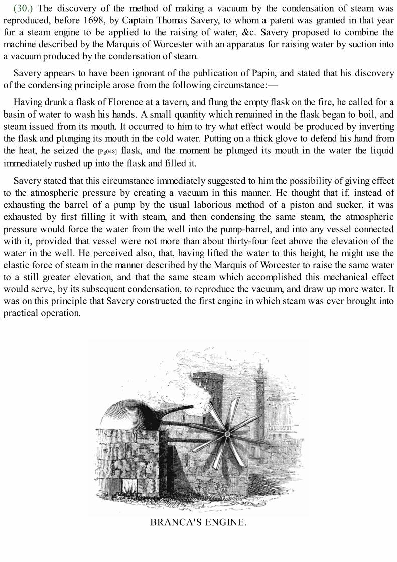
(30.) The discovery of the method of making a vacuum by the condensation of steam wasreproduced, before 1698, by Captain Thomas Savery, to whom a patent was granted in that yearfor a steam engine to be applied to the raising of water, &c. Savery proposed to combine themachine described by the Marquis of Worcester with an apparatus for raising water by suction intoa vacuum produced by the condensation of steam.
Savery appears to have been ignorant of the publication of Papin, and stated that his discoveryof the condensing principle arose from the following circumstance:—
Having drunk a flask of Florence at a tavern, and flung the empty flask on the fire, he called for abasin of water to wash his hands. A small quantity which remained in the flask began to boil, andsteam issued from its mouth. It occurred to him to try what effect would be produced by invertingthe flask and plunging its mouth in the cold water. Putting on a thick glove to defend his hand fromthe heat, he seized the [Pg048] flask, and the moment he plunged its mouth in the water the liquidimmediately rushed up into the flask and filled it.
Savery stated that this circumstance immediately suggested to him the possibility of giving effectto the atmospheric pressure by creating a vacuum in this manner. He thought that if, instead ofexhausting the barrel of a pump by the usual laborious method of a piston and sucker, it wasexhausted by first filling it with steam, and then condensing the same steam, the atmosphericpressure would force the water from the well into the pump-barrel, and into any vessel connectedwith it, provided that vessel were not more than about thirty-four feet above the elevation of thewater in the well. He perceived also, that, having lifted the water to this height, he might use theelastic force of steam in the manner described by the Marquis of Worcester to raise the same waterto a still greater elevation, and that the same steam which accomplished this mechanical effectwould serve, by its subsequent condensation, to reproduce the vacuum, and draw up more water. Itwas on this principle that Savery constructed the first engine in which steam was ever brought intopractical operation.
BRANCA'S ENGINE.

FOOTNOTES:[1] Arago, Eloge historique de James Watt; p. 22.
[2] Ibid., p. 21. note.
[3] Farey, Treatise on the Steam Engine, p. 93.
[4] Arago, sur les Machines à Vapeur, Annuaire, 1829, p. 165
[5] SPIRIT US , breath or air.
[6] Exactly 15·68 oz. = 0·98 lb.
[7] This experiment with the tube A requires to be very carefully executed, and the tube should be one of small bore.
[8] Recueil de diverses Pièces touchant quelques nouvelles Machines, p. 38.
SAVERY'S ENGINE.

CHAP. II.
ENGINES OF SAVERY AND NEWCOMEN.[Pg049]
TOC INX
SAVERY'S ENGINE.—BOILERS AND THEIR APPENDAGES.—WORKING APPARATUS.—MODE OF OPERATION.—DEFECTS OF THE ENGINE.—NEWCOMEN AND CAWLEY.—ATMOSPHERIC ENGINE.—ACCIDENTALDISCOVERY OF CONDENSATION BY INJECTION.—HUMPHREY POTTER MAKES THE ENGINE WORKITSELF.—ADVANTAGES OF THE ATMOSPHERIC ENGINE OVER THAT OF SAVERY.—IT CONTAINED NONEW PRINCIPLE.—ITS PRACTICAL SUPERIORITY.
(31.) The steam engine contrived by Savery, like every other which has since been constructed,consists of two parts, essentially distinct. The first is that which is employed to [Pg050] generate thesteam, which is called the boiler; and the second, that in which the steam is applied as a movingpower.
Fig. 11.
The former apparatus in Savery's engine consists of two strong boilers, sections of which arerepresented at D and E in fig. 11.; D the greater boiler, and E the less. The tubes T and T′
communicate with the working apparatus, which we shall presently describe. A thin plate of metalR, is applied closely to the top of the great boiler D, turning on a centre C, so that by moving a leverapplied to the axis C on the outside of the top, the sliding plate R can be brought from the mouth ofthe one tube to the mouth of the other alternately. This sliding valve is called the regulator, since itis by it that the communications between the boiler and two steam vessels (hereafter described)are alternately opened and closed, the lever which effects this being moved at intervals by the handof the attendant.
Two gauge cocks are represented at G, G′, the use of which is to determine the depth of water inthe boiler. One, G, has its lower aperture a little above the proper depth; and the other, G′, a littlebelow it. Cocks are attached to the upper ends G, G′, which can be opened or closed at pleasure.The steam collected in the top of the boiler pressing on the surface of the water, forces it up in thetubes G, G′, if their lower ends be immersed. Upon opening the cocks G, G′, if water be forced fromboth, there is too much water in the boiler, since the mouth of G is below its level. If steam issue

from both, there is too little water in the boiler, since the mouth of G′ is above its level. But ifsteam issue from G, and water from G′, the water in the boiler is at its proper level. This ingeniouscontrivance for determining the level of the water in the boiler is the invention of Savery, and isused in many instances at the present day.
The mouth of the pipe G should be at a level of a little less [Pg051] than one third of the wholedepth, and the mouth of G′ at a level little lower than one third; for it is requisite that about twothirds of the boiler should be kept filled with water. The tube I forms a communication between thegreater boiler D and the lesser or feeding boiler E, descending nearly to the bottom of it. Thiscommunication can be opened and closed at pleasure by the cock K. A gauge pipe is insertedsimilar to G, G′, but extending nearly to the bottom. From this boiler a tube F extends, which iscontinued to a cistern C (fig. 12.), and a cock is placed at M, which, when opened, allows thewater from the cistern to flow into the feeding boiler E, and which is closed when that boiler isfilled. The manner in which this cistern is supplied will be described hereafter.
Let us now suppose that the principal boiler is filled to the level between the gauge pipes, andthat the subsidiary boiler is nearly full of water, the cock K and the gauge cocks G G′ being allclosed. The fire being lighted beneath D, and the water boiled, steam is produced, and istransmitted through one or other of the tubes T, T′, to the working apparatus. When evaporation hasreduced the water in D below the level of G′, it will be necessary to replenish the boiler D. This iseffected thus:—A fire being lighted beneath the feeding boiler E, steam is produced in it above thesurface of the water, which, having no escape, presses on the surface so as to force it up in the pipeI. The cock K being then opened, the boiling water is forced into the principal boiler D, into whichit is allowed to flow until water issues from the gauge cock G′. When this takes place, the cock K isclosed, and the fire removed from E until the great boiler again wants replenishing. When thefeeding boiler E has been exhausted, it is replenished from the cistern C (fig. 12.), through the pipeF, by opening the cock M.
(32.) We shall now describe the working apparatus in which the steam is used as a movingpower.
Let V V′ (fig. 12.) be two steam vessels communicating by the tubes T T′ (marked by the sameletters in fig. 11.) with the greater boiler D.

Fig. 12.
Let S be a pipe, called the suction pipe, descending into [Pg052] the well or reservoir from whichthe water is to be raised, and communicating with each of the steam vessels through tubes D D′, byvalves A A′, which open upwards. Let F be a pipe continued from the level of the engine towhatever higher level it is intended to elevate the water. The steam vessels V V′ communicate withthe force-pipe F by valves B B′, which open upwards, through the tubes E E′. Over the steam vesselsand on the force-pipe is placed a small cistern C, already mentioned, which is kept filled with coldwater from the force-pipe, and from the bottom of which proceeds a pipe terminated with a cock G.This is called the condensing pipe, and can be brought alternately over each steam vessel. Fromthis cistern another pipe communicates with the feeding boiler (fig. 11.), by the cock M.[9]
The communication of the pipes T T′ with the boiler can be opened and closed alternately, by theregulator R (fig. 11.), already described.
Now suppose the steam vessels and tubes to be all filled with common atmospheric air, and thatthe regulator be placed so that the communication between the tube T and the boiler be opened, thecommunication between the other tube T′ and the boiler being closed, steam will flow into V
through T. At first, while the vessel V is cold, the steam will be condensed, and will fall in dropsof water on the bottom and sides of the vessel. The continued supply of steam from the boiler willat length impart such a degree of heat to the vessel V, that it will cease to condense it. Mixed withthe heated air [Pg053] contained in the vessel V, it will have an elastic force greater than theatmospheric pressure, and will therefore force open the valve B, through which a mixture of airand steam will be driven until all the air in the vessel V will have passed out, and it will containnothing but the pure vapour of water.
When this has taken place, suppose the regulator be moved so as to close the communicationbetween the tube T and the boiler, and to stop the further supply of steam to the vessel V; and at thesame time let the condensing pipe G be brought over the vessel V, and the cock opened so as to let

a stream of cold water flow upon it. This will cool the vessel V, and the steam with which it isfilled will be condensed and fall in a few drops of water, leaving the interior of the vessel avacuum. The valve B will be kept closed by the atmospheric pressure. But the elastic force of theair between the valve A and the surface of the water in the well, or reservoir, will open A, so that apart of this air will rush in, and occupy the vessel V. The air in the suction pipe S, being thusallowed an increased space, will be proportionally diminished in its elastic force, and its pressurewill no longer balance that of the atmosphere acting on the external surface of the water in thereservoir. This pressure will, therefore, force water up in the tube S until its weight, together withthe elastic force of the air above it, balances the atmospheric pressure. When this has taken place,the water will cease to ascend.
Let us now suppose that, by shifting the regulator, the communication is opened between T andthe boiler, so that steam flows again into V. The condensing cock G being removed, the vessel willbe again heated as before, the air expelled, and its place filled by the steam. The condensing pipebeing again allowed to play upon the vessel V, and the further supply of steam being stopped, avacuum will be produced in V, and the atmospheric pressure will force the water through the valveA into the vessel V, which it will nearly fill, a small quantity of air, however, remaining above it.
Thus far the mechanical agency employed in elevating the water is the atmospheric pressure;and the power of steam is no further employed than in the production of a vacuum. [Pg054] But, inorder to continue the elevation of the water through the force pipe F, above the level of the steamvessel, it will be necessary to use the elastic pressure of the steam. The vessel V is now nearlyfilled by the water which has been forced into it by the atmosphere. Let us suppose that, theregulator being shifted again, the communication between the tube T and the boiler is opened, thecondensing cock removed, and that steam flows into V. At first, coming in contact with the coldsurface of the water and that of the vessel, it is condensed; but the vessel is soon heated, and thewater formed by the condensed steam collects in a sheet or film upon the surface of the water in V,so as to form a surface as hot as boiling water.[10] The steam then being no longer condensed,presses on the surface of the water with its elastic force; and when that pressure becomes greaterthan the atmospheric pressure, the valve B is forced open, and the water issuing through it, passesthrough E into the force-pipe F; and this is continued until the steam has forced all the water from V,and occupies its place.
The further admission of steam through T is once more stopped by moving the regulator; and thecondensing pipe being again allowed to play on V, so as to condense the steam which fills it,produces a vacuum. Into this vacuum, as before, the atmospheric pressure will force the water, andfill the vessel V. The condensing pipe being then closed, and steam admitted through T, the water inV will be forced by its pressure through the valve B and tube E into F, and so the process iscontinued.
We have not yet noticed the other steam vessel V′, which, as far as we have described, wouldhave remained filled with common atmospheric air, the pressure of which on the valve A′ wouldhave prevented the water raised in the suction pipe S from passing through it. However, this is notthe case; for, during the entire process which has been described in V, similar effects have beenproduced in V′, which we have only omitted to notice to avoid the confusion which the twoprocesses might produce. It will be remembered, that after the steam, in the first instance, having

flowed from the boiler [Pg055] through T, has blown the air out of V through B, the communicationbetween T and the boiler is closed. Now the same motion of the regulator which closes this, opensthe communication between T′ and the boiler; for the sliding plate R (fig. 11.) is moved from theone tube to the other, and at the same time, as we have already stated, the condensing pipe isbrought to play on V. While, therefore, a vacuum is being formed in V by condensation, the steam,flowing through T′, blows out the air through B′, as already described in the other vessel V; andwhile the air in S is rushing up through A into V, followed by the water raised in S by theatmospheric pressure, the vessel V′ is being filled with steam, and the air is completely expelledfrom it.
The communication between T and the boiler is now again opened, and the communicationbetween T′ and the boiler closed by moving the regulator R (fig. 11.) from the tube T to T′; at thesame time the condensing pipe is removed from over V, and brought to play upon V′. While thesteam once more expels the air from V through B, a vacuum is formed by condensation in V′, intowhich the water in S rushes through the valve A′. In the mean time V is again filled with steam. Thecommunication between T and the boiler is now closed, and that between T′ and the boiler isopened, and the condensing pipe removed from V′, and brought to play on V. While the steam fromthe boiler forces the water in V′ through B′ into the force-pipe F, a vacuum is being produced in V,into which water is raised by the atmospheric pressure.
Thus each of the vessels V V′ is alternately filled from S, and the water thence forced into F. Thesame steam which forces the water from the vessels into F, having done its duty, is condensed, andbrings up the water from S, by giving effect to the atmospheric pressure.
During this process, two alternate motions or adjustments must be constantly made; thecommunication between T and the boiler must be opened, and that between T′ and the boiler closed,which is done by one motion of the regulator. The condensing pipe at the same time must bebrought from V to play on V′, which is done by the lever placed upon it. Again [Pg056] thecommunication between T′ and the boiler is to be opened, and that between T and the boiler closed;this is done by moving back the regulator. The condensing pipe is brought from V′ to V by movingback the other lever, and so on alternately.
For the clearness and convenience of description, some slight and otherwise unimportantchanges have been made in the position of the parts. A perspective view of this engine isrepresented at the head of this chapter. The different parts already described will easily berecognised.
The engine of Savery was very clearly described in a small work published in London in 1702,entitled, The Miner's Friend, or an Engine to raise Water by Fire described, and the Manner ofFixing it in Mines; with an Account of the several Uses it is applicable unto, and an Answer tothe Objection made against it; by Thomas Savery, Gentleman. This volume was dedicated toWilliam III. (to whom the engine had been exhibited at Hampton Court palace), to the RoyalSociety, and to the mining adventurers of England. The following are the uses to which Saveryproposed the engine should be applied: First, to raise water for turning all sorts of mills; second,supplying palaces and houses with water, and supplying means of extinguishing fire therein by thewater so raised; third, the supplying cities and towns with water; fourth, draining fens or marshes;fifth, for ships; sixth, the drainage of mines.

Dr. Harris, in his Lexicon Technicum, or Dictionary of Arts and Sciences, mentions a machineof Savery's for propelling a vessel in a calm, by paddle-wheels placed at the side; but it does notappear that Savery contemplated the application of a steam engine to work these wheels.
It is only from scattered passages in publications of the day that it can be ascertained to whatextent the engines of Savery were practically applied. In his address to the Royal Society, hespeaks of the "difficulties and expense which he encountered in instructing artisans to makeengines according to his wish; but that after much experience the workmen had become suchmasters of the thing, that they bound themselves to deliver the engines 'exactly tight and fit for [Pg057]
service, and such as he (Savery) dare warrant them to every one that has occasion for them.'"
In his address to the miners of England he also says, "that the frequent disorders andcumbersomeness of water engines then in use encouraged him to invent engines to work by thisnew force; that though they were obliged to encounter the oddest and almost insuperabledifficulties, yet he spared neither time, pains, nor money, till he had conquered them."
In Bradley's Improvements of Planting and Gardening, 1718, the author thus speaks of anengine erected by Savery:—
"Supposing the situation of a house or garden to be a considerable height above any pond, river,or spring, and that it has at present no other conveniency of water than what is brought continuallyby men or horses to it. In this case, the wonderful invention of the late Mr. Savery, F.R.S., forraising water by fire, will not only supply the defect, by flinging up as much water as may bedesired, but may be maintained with very little trouble and very small expense.
"It is now about six years since Mr. Savery set up one of them for that curious gentleman Mr.Balle, at Cambden House, Kensington, near London, which has succeeded so well that there hasnot been any want of water since it has been built; and, with the improvements since made to it, Iam apt to believe will be less subject to be out of order than any engine whatever."
It is remarkable that, notwithstanding the high pressure steam necessary for the operation ofSavery's engine, he does not appear to have adopted the obvious expedient of a safety valve. Thesafety valve had been previously known, having been invented about the year 1681, by Papin, forhis digester, which was a close boiler, contrived by him for stewing meat and digesting bones, bysubmitting them to a higher temperature than that of water boiling in an open vessel.
The safety valve which has ever since been used for steam boilers of every kind is a valvewhich opens outwards, and is fitted to an aperture in the boiler, so as to be steam tight. It ispressed down by a weight, the amount of which is regulated by the maximum pressure to which itis intended the steam [Pg058] shall be limited. Thus, if the magnitude of the valve be a square inch,and the pressure of the steam be limited to 10 lbs. per square inch above the pressure of theatmosphere, then the valve would be loaded with a weight of 10 lbs.; but as it was found necessaryto vary from time to time the limiting pressure of the steam, or the load of the safety valve, thesevalves were usually constructed so as to be held down by the pressure of a lever having a slidingweight upon it. By moving the weight on the arm of the lever, the pressure on the valve could beincreased or diminished at the discretion of the engineer. This contrivance was first applied toSavery's engines, by Desaguliers, about the year 1717, before which year Savery died.
It is justly observed by Mr. Farey, in his treatise on the steam engine, that, "when a comparisonis made between Captain[11] Savery's engine and those of his predecessors, the result will be in

every respect favourable to his character as an inventor, and as a practical engineer; all the detailsof his invention are made out in a masterly style, and accidents and contingencies are provided for,so as to render it a real working engine; whereas De Caus, the Marquis of Worcester, Sir SamuelMorland, and Papin, though ingenious philosophers, only produced mere outlines, which requiredgreat labour and skill of subsequent inventors to fill up, and make them sufficiently complete to beput in execution."
About the year 1718 further improvements were made in the construction of Savery's engine, byDr. Desaguliers; but it is probable that some of these were suggested by the proceedings of theinventors of the atmospheric engine, which shall presently describe.
(33.) In order duly to appreciate the value of improvements, it is necessary first to perceive thedefects which these improvements are designed to remove. Savery's steam engine, consideringhow little was known of the value and properties of steam, and how low the general standard ofmechanical knowledge was in his day, is certainly highly [Pg059] creditable to his genius.Nevertheless it had very considerable defects, and was finally found to be inefficient for the mostimportant purposes to which he proposed applying it.
At the time of this invention, the mines in England had greatly increased in depth, and theprocess of draining them had become both expensive and difficult; so much so, that it was found inmany instances that their produce did not cover the cost of working them. The drainage of thesemines was the most important purpose to which Savery proposed to apply his steam engine.
It has been already stated that the pressure of the atmosphere amounts to about fifteen pounds onevery square inch. Now, a column of water, whose base is one square inch, and whose height isthirty-four feet, weighs about fifteen pounds. If we suppose that a perfect vacuum were produced inthe steam vessels V V′ (fig. 12.) by condensation, the atmospheric pressure would fail to force upthe water, if the height of the top of these vessels above the water to be raised exceeded thirty-fourfeet. It is plain, therefore, that the engine cannot be more than thirty-four feet above the waterwhich it is intended to elevate. But in fact it cannot be so much; for the vacuum produced in thesteam vessels V V′ is never perfect. Water, when not submitted to the pressure of the atmosphere,will vaporise at a very low temperature, as we shall hereafter explain; and it was found that avapour possessing a considerable elasticity would, notwithstanding the condensation, remain in thevessels V V′ and the pipe S, and would oppose the ascent of the water. In consequence of this, theengine could never be placed with practical advantage at a greater height than twenty-six feetabove the level of the water to be raised.
(34.) When the water is elevated to the engine, and the steam vessels filled, if steam beintroduced above the water in V, it must first balance the atmospheric pressure, before it can forcethe water through the valve B. Here, then, is a mechanical pressure of fifteen pounds per squareinch expended, without any water being raised by it. If steam of twice that elastic force be used, itwill elevate a column in F of thirty-four feet in height; and if steam of triple the force be used, itwill raise a column of sixty-eight feet high, [Pg060] which, added to twenty-six feet raised by theatmosphere, gives a total lift of ninety-four feet.
In effecting this, steam of a pressure equal to three times that of the atmosphere acts on the innersurface of the vessels V V′. One third of this bursting pressure is balanced by the pressure of theatmosphere on the external surface of the vessels; but an effective pressure of thirty pounds per

square inch still remains, tending to burst the vessels. It was found that the apparatus could not beconstructed to bear more than this with safety; and, therefore, in practice, the lift of such an enginewas limited to about ninety perpendicular feet. In order to raise the water from the bottom of themine by these engines, therefore, it was necessary to place one at every ninety feet of the depth; sothat the water raised by one through the first ninety feet should be received in a reservoir, fromwhich it was to be elevated the next ninety feet by another, and so on.
Besides this, it was found that sufficient strength could not be given to those engines, ifconstructed upon a large scale.
They were, therefore, necessarily very limited in their dimensions, and were incapable ofraising the water with sufficient speed. Hence arose a necessity for several engines at each level,which greatly increased the expense.
(35.) These, however, were not the only defects of Savery's engines. The consumption of fuelwas enormous, the proportion of heat wasted being much more than what was used in eitherforcing up the water, or producing a vacuum. This will be very easily understood by attending tothe process of working the engine already described.
When the steam is first introduced from the boiler into the steam vessels V V′, preparatory to theformation of a vacuum, it is necessary that it should heat these vessels up to the temperature of thesteam itself; for until then the steam will be condensed the moment it enters the vessel by the coldsurface. All this heat, therefore, spent in raising the temperature of the steam vessels is wasted.Again, when the water has ascended and filled the vessels V V′, and steam is introduced to forcethis water through B B′ into F, it is immediately condensed by the cold surface in V V′, and does not[Pg061] begin to act until a quantity of hot water, formed by condensed steam, is collected on thesurface of the cold water which fills these vessels. Hence another source of the waste of heatarises.
When the steam begins to act upon the surface of the water in V V′, and to force it down, the coldsurface of the vessels is gradually exposed to the steam, and must be heated while the steamcontinues its action; and when the water has been forced out of the vessel, the vessel itself hasbeen heated to the temperature of the steam which fills it, all which heat is dissipated by thesubsequent process of condensation. It must thus be evident that the steam used in forcing up thewater in F, and in producing a vacuum, bears a very small proportion indeed to what is consumedin heating the apparatus after condensation.
(36.) There is also another circumstance which increases the consumption of fuel. The watermust be forced through B, not only against the atmospheric pressure, but also against a column ofsixty-eight feet of water. Steam is therefore required of a pressure of forty-five pounds on thesquare inch. Consequently the water in the boiler must be boiled under this pressure. That thisshould take place, it is necessary that the water should be raised to a temperature considerablyabove 212°, even so high as 275°; and thus an increased heat must be given to the boiler.Independently of the other defects, this intense heat weakened and gradually destroyed theapparatus.
Savery was the first who suggested the method of expressing the power of an engine withreference to that of horses. In this comparison, however, he supposed each horse to work but eighthours a day, while the engine works for twenty-four hours. This method of expressing the power of
steam engines will be explained hereafter.
(37.) The failure of the engines proposed by Captain Savery in the work of drainage, from thecauses which have been just mentioned, and the increasing necessity for effecting this object,arising from the large property in mines which became every year unproductive by being flooded,stimulated the ingenuity [Pg062] of mechanics to contrive some means of rendering those powers ofsteam exhibited in Savery's engine available.
Thomas Newcomen, the reputed inventor of the atmospheric engine, was an ironmonger, or,according to some, a blacksmith, in the town of Dartmouth in Devonshire. From his personalacquaintance and intercourse with Dr. Hooke, the celebrated natural philosopher, it is probablethat he was a person of some education, and therefore likely to be above the position of ablacksmith. Being in the habit of visiting the tin mines in Cornwall, Newcomen became acquaintedwith the engine invented by Savery, and with the causes which led to its inefficiency for thepurposes of drainage.
It has been stated that Papin, about the year 1690, proposed the construction of an engineworking by the atmospheric pressure acting on one side of a piston against a vacuum produced bythe condensation of steam on the other side. Papin was not conscious of the importance of thisprinciple; for, so far from ever having attempted to apply it to practical purposes, he probablynever constructed, even on a small scale, any machine illustrating it. On the contrary, he abandonedthe project the moment he was informed of the principle and structure of the steam engine ofSavery; and he then proposed an engine for raising water, acting by the expansive force of steamsimilar to Savery's, but abandoning the method of working by a vacuum.
This engine is described by Papin in a work published in 1707.

Fig. 13.
A (fig. 13.) is an oval boiler, having a safety-valve B, which limits the pressure of the steam. Itis connected with a cylinder C, by a curved pipe having a stop-cock at D. A pipe with a stop-cockG opens from the top of the cylinder into the atmosphere, and a safety-valve F is placed upon thecylinder. A hollow copper piston H moves freely in the cylinder, and floats upon the water. O is afunnel with a valve L in the bottom, opening downwards, through which the cylinder C may befilled with water to the level of the top of the funnel. A close air-vessel communicates with thecylinder C by the curved tube, and has a valve K opening upwards. The force-pipe through whichthe water is raised communicates [Pg063] with the air-vessel I. If the cock D be shut, and the cock G
opened, water poured into the funnel O will rise into the cylinder C, the air which fills the cylinderescaping through the open pipe G. When the cylinder is thus filled with water, let the cock G beclosed, and the cock D opened. The steam from the boiler, after heating the metal of the cylinder,will force the piston downwards, and drive the water through the curved tube into the vessel I,from which its return is prevented by the valve K, which is closed by its weight. The air whichfilled the vessel I will then be compressed, and by its elasticity will drive a column of water upthe pipe N. After the contents of the cylinder have been thus discharged it may be refilled in thesame manner, and the process repeated.
It will be perceived that this project is nothing more than a reproduction of the engine of theMarquis of Worcester. In the preface to the work containing this description, Papin gives an extractfrom a letter addressed by him to Leibnitz in 1698, from which it appears that he had abandonedhis idea of working the piston by the atmospheric pressure acting against a vacuum, considering itto be a contrivance inferior [Pg064] to the engine now described. "We now raise water," he says, "bythe force of fire, in a more advantageous manner than that which I had published some yearsbefore; for besides the suction, we now also use the pressure which the water exerts upon other

bodies in dilating itself by heat; instead of which I before employed the suction only, the effects ofwhich are more limited."
From documents which have been preserved in the Royal Society, it appears that Newcomenwas acquainted with Papin's writings, and therefore probably first derived from them thesuggestion which he subsequently realised in the atmospheric engine. Among some papers of Dr.Hooke's have been found notes for the use of Newcomen, on Papin's method of transmitting theforce of a stream or fall of water to a distance by pipes. Hooke dissuaded Newcomen fromattempting any machine on this principle, which, as first proposed by Papin, was impracticable.He exposed the fallacy of Papin's first project in several discourses before the Royal Society, andconsidered his improved edition of it, though free from fallacy, as impracticable.
Papin's project for producing a vacuum under a piston by condensing the steam having beenpublished in the Actæ Eruditorum, in Latin, in 1690, and in French, at Cassel, in 1695, andsubsequently, in the Philosophical Transactions, in England in 1697, cannot be supposed to beunknown to Dr. Hooke; and if known to him, would probably have been communicated toNewcomen. Dr. Hooke died in 1703, some years before the date of Newcomen's invention.
John Cawley, who was the associate of Newcomen in his experiments and inquiries, was aplumber and glazier of the same town. Newcomen and Cawley obtained a patent for theatmospheric engine in 1705, in which Savery was associated, he having previously obtained apatent for the method of producing a vacuum by the condensation of steam, which was essential toNewcomen's contrivance. It was not, however, until about the year 1711 that any engine had beenconstructed under this patent.
In the latter end of that year, according to Desaguliers, the patentees "made proposals to drain acolliery at Griff, in [Pg065] Warwickshire, in which work five hundred horses were constantlyemployed. This proposal not being accepted, they contracted, in the following March, to drainwater for Mr. Back of Wolverhampton, where, after many laborious attempts, they succeeded inmaking their engine work; but not being either philosophers to understand the reason, ormathematicians enough to calculate the power and proportions of the parts, they very luckily, byaccident, found what they sought for."

Fig. 14.
Newcomen resumed the old method of raising the water from the mines by ordinary pumps, butconceived the idea of working these pumps by some moving power less expensive than that ofhorses. The means whereby he proposed effecting this, was by connecting the end of the pump-rodD (fig. 14.) by a chain with the arch head A of a [Pg066] working-beam A B, playing on an axis C. Theother arch head B of this beam was connected by a chain with the rod E of a solid piston P, whichmoved air-tight in a cylinder F. If a vacuum be created beneath the piston P, the atmosphericpressure acting upon it will press it down with a force of fifteen pounds per square inch; and theend A of the beam being thus raised, the pump-rod D will be drawn up. If a pressure equivalent tothe atmosphere be then introduced below the piston, so as to neutralise the downward pressure, thepiston will be in a state of indifference as to the rising or falling; and if in this case the rod D bemade heavier than the piston and its rod, so as to overcome the friction, it will descend, andelevate the piston again to the top of the cylinder. The vacuum being again produced, anotherdescent of the piston, and consequent elevation of the pump-rod, will take place; and so theprocess may be continued.
Such was Newcomen's first conception of the atmospheric engine; and the contrivance hadmuch, even at the first view, to recommend it. The power of such a machine would depend entirely

on the magnitude of the piston; and being independent of highly elastic steam, would not expose thematerials to the destructive heat which was necessary for working Savery's engine. Supposing aperfect vacuum to be produced under the piston in the cylinder, an effective downward pressurewould be obtained, amounting to fifteen times as many pounds as there are square inches in thesection of the piston.[12] Thus, if the base of the piston were 100 square inches, a pressure equal to1500 pounds would be obtained.
(38.) In order to accomplish this, two things were necessary: 1. To make a speedy and effectualvacuum below the [Pg067] piston in the descent; and, 2. To contrive a counterpoise for the atmospherein the ascent.
The condensation of steam immediately presented itself as the most effectual means ofaccomplishing the former; and the elastic force of the same steam previous to condensation anobvious method of effecting the latter. Nothing now remained to carry the design into execution, butthe contrivance of means for the alternate introduction and condensation of the steam; andNewcomen and Cawley were accordingly granted a patent in 1707, in which Savery was united, inconsequence of the principle of condensation for which he had previously received a patent beingnecessary to the projected machine. We shall now describe the atmospheric engine, as firstconstructed by Newcomen:—
The boiler K (fig. 14.) is placed over a furnace I, the flue of which winds round it, so as tocommunicate heat to every part of the bottom of it. In the top, which is hemispherical, two gauge-cocks G G′ are placed, as in Savery's engine, and a puppet valve V, which opens upward, and isloaded at one pound per square inch; so that when the steam produced in the boiler exceeds thepressure of the atmosphere by more than one pound on the square inch, the valve V is lifted, and thesteam escapes through it, and continues to escape until its pressure is sufficiently diminished, whenthe valve V again falls into its seat. This valve performs the office of the safety-valve in modernengines.
The great steam-tube is represented at S, which conducts steam from the boiler to the cylinder;and a feeding pipe T, furnished with a cock, which is opened and closed at pleasure, proceedsfrom a cistern L to the boiler. By this pipe the boiler may be replenished from the cistern, when thegauge cock G′ indicates that the level has fallen below it. The cistern L is supplied with hot water,by means which we shall presently explain.
(39.) To understand the mechanism necessary to work the piston, let us consider how the supplyand condensation of steam must be regulated. When the piston has been forced to the bottom of thecylinder by the atmospheric pressure acting against a vacuum, in order to balance that pressure,[Pg068] and enable it to be drawn up by the weight of the pump-rod, it is necessary to introduce steamfrom the boiler. This is accomplished by opening the cock R in the steam pipe S. The steam beingthus introduced from the boiler, its pressure balances the action of the atmosphere upon the piston,which is immediately drawn to the top of the cylinder by the weight of the pump-rod D. It thenbecomes necessary to condense this steam, in order to produce a vacuum. To accomplish this, thefurther supply of steam must be cut off, which is done by closing the cock R. The supply of steamfrom the boiler being thus suspended, the application of cold water on the external surface of thecylinder becomes necessary to condense the steam within it. This was done by enclosing thecylinder within another, leaving a space between them.[13] Into this space cold water was allowed

to flow from a cock M placed over it, supplied by a pipe from the cistern N. This cistern issupplied with water by a pump O, which is worked by the engine.
The cold water supplied from M, having filled the space between the two cylinders, abstractsthe heat from the inner one; and condensing the steam, produces a vacuum, into which the piston isforced by the atmospheric pressure. Preparatory to the next descent, the water which thus fills thespace between the cylinders, and which is warmed by the heat abstracted from the steam, must bedischarged, in order to give room for a fresh supply of cold water from M. An aperture, furnishedwith a cock, is accordingly provided in the bottom of the cylinder, through which the water isdischarged into the cistern L; and being warm, is adapted for the supply of the boiler through T, asalready mentioned.
The cock R being now again opened, steam is admitted below the piston, which, as before,ascends, and the descent is again accomplished by closing the cock R, and opening the cock M,admitting cold water between the cylinders, and thereby condensing the steam below the piston.
The condensed steam, thus reduced to water, will collect [Pg069] in the bottom of the cylinder, andresist the descent of the piston. It is therefore necessary to provide an exit for it, which is done bya valve opening outwards into a tube which leads to the feeding cistern L, into which thecondensed steam is driven.
That the piston should continue to be air-tight, it was necessary to keep a constant supply ofwater over it; this was done by a cock similar to M, which allowed water to flow from the pipe Mon the piston.
(40.) Soon after the first construction of these engines, an accidental circumstance suggested toNewcomen a much better method of condensation than the application of cold water on the externalsurface of the cylinder. An engine was observed to work several strokes with unusual rapidity, andwithout the regular supply of the condensing water. Upon examining the piston, a hole was found init, through which the water, which was poured on to keep it air-tight, flowed, and instantlycondensed the steam under it.
On this suggestion Newcomen abandoned the external cylinder, and introduced a pipe H,furnished with a cock Q, into the bottom of the cylinder, so that, on turning the cock, the pressure ofthe water in the pipe H, from the level of the water in the cistern N, would force the water to rise asa jet into the cylinder, and would instantly condense the steam. This method of condensing byinjection formed a very important improvement in the engine, and is still used.
(41.) Having taken a general view of the parts of the atmospheric engine, let us now considermore particularly its operation.
When the engine is not working, the weight of the pump-rod D (fig. 14.) draws down the beam A,and draws the piston to the top of the cylinder, where it rests. Let us suppose all the cocks andvalves closed, and the boiler filled to the proper depth. The fire being lighted beneath it, the wateris boiled until the steam acquires sufficient force to lift the valve V. When this takes place, theengine may be started. For this purpose the regulating valve R is opened. The steam rushes in, andis first condensed by the cold cylinder. After a short time the cylinder acquires the temperature ofthe steam, which then [Pg070] ceases to be condensed, and mixes with the air which filled thecylinder. The steam and heated air, having a greater force than the atmospheric pressure, will open

a valve placed at the end X of a small tube in the bottom of the cylinder, and which opensoutwards. From this (which is called the blowing valve[14]) the steam and air rush in a constantstream, until all the air has been expelled, and the cylinder is filled with the pure vapour of water.This process is called blowing the engine preparatory to starting it.
When it is about to be started, the engine-man closes the regulator R, and thereby suspends thesupply of steam from the boiler. At the same time he opens the condensing valve H[15]; and therebythrows up a jet of cold water into the cylinder. This immediately condenses the steam contained inthe cylinder, and produces the vacuum. (The atmosphere cannot enter the blowing valve, because itopens outwards, so that no air can enter to vitiate the vacuum.) The atmospheric pressure abovethe piston now takes effect, and forces it down in the cylinder. The descent being completed, theengine-man closes the condensing valve H, and opens the regulator, R. By this means he stops theplay of the jet within the cylinder, and admits the steam from the boiler. The first effect of the steamis to expel the condensing water and condensed steam which are collected in the bottom of thecylinder, through the tube Y, containing a valve which opens outwards (called the eduction valve),which leads to the hot cistern L, into which this water is therefore discharged.
When the steam admitted through R ceases to be condensed, it balances the atmospheric pressureabove the piston, and thus permits it to be drawn to the top of the cylinder by the weight of the rodD. This ascent of the piston is also assisted by the circumstance of the steam being somewhatstronger than the atmosphere.
When the piston has reached the top, the regulating valve R is closed, and the condensing valveH opened, and another descent produced, as before, and so the process is continued. [Pg071]
The manipulation necessary in working this engine was, therefore, the alternate opening andclosing of two valves; the regulating and condensing valves. When the piston reached the top of thecylinder, the former was to be closed, and the latter opened; and, on reaching the bottom, theformer was to be opened, and the latter closed.
(42.) The duty of working the engine requiring no great amount of labour, or skill, was usuallyentrusted to boys, called, cock boys. It happened that one of the most important improvementswhich has ever been made in the working of steam engines was due to the ingenuity of one of theseboys. It is said that a lad, named Humphrey Potter, was employed to work the cocks of anatmospheric engine, and being tempted to escape from the monotonous drudgery to which his dutyconfined him, his ingenuity was sharpened so as to prompt him to devise some means by which hemight indulge his disposition to play without exposing himself to the consequences of suspendingthe performance of the engine. On observing the alternate ascending and descending motion of thebeam above him, and considering it in reference to the labour of his own hands, in alternatelyraising and lowering the levers which governed the cocks, he perceived a relation which served asa clue to a simple contrivance, by which the steam engine, for the first time, became an automaton.When the beam arrived at the top of its play, it was necessary to open the steam valve by raising alever, and to close the injection valve by raising another. This he saw could be accomplished byattaching strings of proper length to these levers, and tying them to some part of the beam. Theselevers required to be moved in the opposite direction when the beam attained the lowest point ofits play. This he saw could be accomplished by strings, either connected with the outer arm of thebeam, or conducted over rods or pulleys. In short, he contrived means of so connecting the levers

which governed the two cocks by strings with the beam, that the beam opened and closed thesecocks with the most perfect regularity and certainty as it moved upwards and downwards.
Besides rendering the machine independent of manual [Pg072] superintendence, this processconferred upon it much greater regularity of performance than any manual superintendence couldensure.
This contrivance of Potter was very soon improved by the substitution of a bar, called a plugframe, which was suspended from the arm of the beam, and which carried upon it pins, by whichthe arms of the levers governing the cocks were struck as the plug-frame ascended and descended,so as to be opened and closed at the proper times.
The engine thus improved required no other attendance except to feed the boiler occasionally bythe cock T, and to attend the furnace.
(43.) However the merit of the discovery of the physical principles on which the mechanicalapplication of steam depends may be awarded, it must be admitted that the engine contrived byNewcomen and his associates, considered as a practical machine, was immeasurably superior tothat which preceded it; superior, indeed, to such a degree, that while the one was incapable of anypermanently useful application, the other soon became a machine of extensive utility in thedrainage of mines; and, even at the present time, the atmospheric engine is not unfrequently used inpreference to the modern steam engine, in districts where fuel is abundant and cheap; the expenseof constructing and maintaining it being considerably less than that of an improved steam engine.The low pressure of the steam used in working it, rendered it perfectly safe. While Savery'sengine, to work with effect, required that the steam confined in the vessels should have a burstingpressure amounting to about thirty pounds per square inch, the pressure of steam in the boiler andcylinder of the atmospheric engine required only a pressure about one pound per square inch. Thehigh pressure also of the steam used in Savery's engine, was necessarily accompanied, as we shallpresently explain, by a greatly increased temperature. The effect of this was, to weaken andgradually destroy the vessels, especially those which, like the steam vessels V and V′ (fig. 12.),were alternately heated and cooled.
Besides these defects, the power of Savery's engines was [Pg073] also very restricted, both as tothe quantity of water raised and as to the height to which it was elevated. On the other hand, theatmospheric engine was limited in its power only by the dimensions of its piston. Anotherconsiderable advantage which the atmospheric engine possessed over that of Savery, was thefacility with which it was capable of driving machinery by means of the working-beam. The merit,however, of Newcomen's engine, regarded as an invention, and apart from merely practicalconsiderations, must be ascribed principally to its mechanism and combinations. We find in it nonew principle, and scarcely even a novel application of a principle. The agency of the atmosphericpressure acting against a vacuum, or partial vacuum, had been long known: the method ofproducing a vacuum by the condensation of steam had been suggested by Papin, and carried intopractical effect by Savery. The mechanical power obtained from the direct pressure of the elasticforce of steam, used in the atmospheric engine to balance the atmosphere during the ascent of thepiston, was suggested by De Caus and Lord Worcester. The boiler, gauge pipes, and the regulator,were all borrowed from the engine of Savery. The idea of using the atmospheric pressure against avacuum or partial vacuum, to work a piston in a cylinder, had been suggested by Otto Guericke, aningenious German philosopher, who invented the air-pump; and this, combined with the production

of a vacuum by the condensation of steam, was subsequently suggested by Papin. The use of aworking-beam could not have been unknown. Nevertheless, the judicious combination of thesescattered principles must be acknowledged to deserve considerable credit. In fact, the mechanismcontrived by Newcomen rendered a machine which was before altogether inefficient, highlyefficient: and, as observed by Tredgold, such a result, considered in a practical sense, should bemore highly valued than the fortuitous discovery of a physical principle. The method of condensingthe steam by the sudden injection of water, and of expelling the air and water from the cylinder bythe injection of steam, are two contrivances not before in use, which are quite essential to the [Pg074]
effective operation of the engine. These processes, which are still necessary to the operation of theimproved steam engine, appear to be wholly due to the inventors of the atmospheric engine.
ATMOSPHERIC ENGINE.

FOOTNOTES:[9] This pipe is represented as proceeding from the force-pipe above the cistern C, in the perspective view of Savery's
engine at the head of this chapter.
[10] Hot water being lighter than cold, floats on the surface.
[11] "Captain" is a title given in Cornwall to the superintendent of the works connected with a mine.
[12] As the calculation of the power of an engine depends on the number of square inches in the section of the piston, itmay be useful to give a rule for computing the number of square inches in a circle. The following rule will alwaysgive the dimensions with sufficient accuracy:—Multiply the number of inches in the diameter by itself; divide theproduct by 14, and multiply the quotient thus obtained by 11, and the result will be the number of squareinches in the circle. Thus, if there be 12 inches in the diameter, this multiplied by itself gives 144, which divided by14 gives 104⁄44, which multiplied by 11 gives 115, neglecting fractions. There are, therefore, 115 square inches in acircle whose diameter is 12 inches.
[13] The external cylinder is not represented in the diagram.
[14] Also called the snifting valve, from the peculiar noise made by the air and steam escaping from it.
[15] Also called the injection valve.
GREENOCK, IN 1824.

CHAP. III.
[Pg075]
TOC INX
PROGRESS OF THE ATMOSPHERIC ENGINE.—SMEATON'S IMPROVEMENTS.—BRINDLEY, ENGINEER OF THEBRIDGEWATER CANAL.—INVENTS THE SELF-REGULATING FEEDER.—JAMES WATT.—HIS DESCENT ANDPARENTAGE.—ANECDOTES OF HIS BOYHOOD.—HIS EARLY ACQUIREMENTS.—GOES TO LONDON.—RETURNS TO GLASGOW.—IS APPOINTED INSTRUMENT-MAKER TO THE UNIVERSITY.—OPENS A SHOPIN GLASGOW.—HIS FRIENDS AND PATRONS.—ADAM SMITH.—DR. BLACK.—ROBERT SIMSON.—PROFESSOR ROBISON.—WATT'S PERSONAL CHARACTER.—INDUSTRIOUS AND STUDIOUS HABITS.—HISATTENTION FIRST DIRECTED TO STEAM.—EXPERIMENTS ON HIGH-PRESSURE STEAM.—REPAIRS ANATMOSPHERIC MODEL.—EXPERIMENTAL INQUIRY CONSEQUENT ON THIS.—ITS RESULTS.—DISCOVERSTHE GREAT DEFECTS OF THE ATMOSPHERIC ENGINE.—DISCOVERY BY EXPERIMENT OF THEEXPANSION WHICH WATER UNDERGOES IN EVAPORATION.—DISCOVERS THE LATENT HEAT OF STEAM.—IS INFORMED BY DR. BLACK OF THE THEORY OF LATENT HEAT.
(44.) The atmospheric engine was brought to a state of considerable efficiency and improvementby Mr. Beighton, in 1718. From that time it continued in use without any change in its [Pg076]
principle, and with little improvement in its structure, for half a century. Although engines of thiskind continued to be extensively constructed, they were usually executed by ordinary mechanics,incapable of applying to them the just principles of practical science; and, consequently, littleattention was paid to their proportions. It was not until about the year 1772, that Mr. John Smeaton,the celebrated engineer, applied the powers of his mind to the investigation of this machine, as hehad previously done with such success to wind and water mills. Although he did not introduce anynew principle into the atmospheric engine, yet it derived greatly augmented power from theproportions which he established for engines of different magnitudes.
In 1759, Mr. James Brindley, whose name is so celebrated as the engineer of the Duke ofBridgewater's canal, obtained a patent for some improvements in the atmospheric engine. Heproposed that the boiler should be made of wood and stone, with a stove or fire-place of cast ironwithin it, so that the fire should be surrounded on every side by water. The chimney was to be aniron pipe or tube, conducted through the boiler; so that the heated air, in passing from the fire,should impart a portion of its heat to the water. He also proposed a method of feeding the boiler,which, by self-acting machinery, would keep the water in the boiler at a fixed level, independentlyof any attention on the part of the engine-man. This was to be accomplished by a buoy or float uponthe surface of the water in the boiler, which should communicate with a valve in the feed-pipe, sothat when the level of the water in the boiler fell, the float or buoy, falling with it, would open thevalve and supply the feed. It is stated, in the Biographia Britannica, that Mr. Brindley, in 1756,undertook to erect an engine at Newcastle-under-Lyne; but he is said to have been discouraged bythe obstacles which were thrown in his way, and to have abandoned the steam engine.
The interval between the invention of the atmospheric engine, and the amelioration it received atthe hands of Smeaton, has been rendered memorable by the advent of one who was destined towork a mighty change in the condition [Pg077] of the human race by the application of his vast geniusto the adaptation of steam power to the uses of life.
(45.) JAMES WATT was born at Greenock, in Scotland, on the nineteenth day of January, in theyear 1736.[16]

The great-grandfather of Watt, a farmer in Aberdeenshire, was killed in one of the battles ofMontrose. The victorious party, not thinking death a sufficient expiation for the political opinionsin support of which he had fought and bled, punished him in the person of his son, by confiscatinghis little property. Thomas Watt, the son, thus deprived of support, was received by distantrelations, and, for a time, applied himself to study, by which he was enabled, after the restorationof tranquillity, to establish himself at Greenock as a teacher of practical mathematics andnavigation. He resided in the burgh or barony of Crawford's Dyke, and attained a position ofsufficient respectability to be elected to the office of baron-baillie, or chief magistrate, and died in1734, at the advanced age of ninety-two years.
Thomas Watt had two sons. The elder, John, adopted the profession of his father, and was ateacher of mathematics and navigation at Glasgow: he died in 1737, at the age of fifty years. Thesecond son, James, the father of the celebrated engineer, was, during a quarter of a century,treasurer of the town council of Greenock, and a local magistrate. He was remarked for the ardentzeal and enlightened spirit with which he discharged his public duties. His business was that of aship-chandler, builder, and general merchant; but, unhappily, notwithstanding his active industry, helost, in the decline of his life, by unsuccessful commercial speculations, a part of the propertywhich he had so honourably acquired. He died in 1782, at the age of eighty-four years.
JAMES WATT , to whom the world is so largely indebted for the extension and improvement ofsteam power, had from his birth an extremely delicate constitution. From his mother, [Pg078] whosefamily name was Muirhead, he received his first lessons in reading, and he learned from his fatherwriting and arithmetic. Although he was entered as a pupil in the grammar school of Greenock, yetsuch was his delicate state of health, that his attendance there was so interrupted by constantindisposition that he could derive but little benefit from the opportunities of instruction which itafforded. For a great period of the year he was confined to his room, where he devoted himself tostudy without the aid of instruction. It was in the retirement of the sick chamber that the highintellectual faculties of Watt, which were destined to produce such precious fruits, began to unfoldthemselves. He was too sickly to be subjected to the restraints which the business of educationusually imposes on children. His parents, therefore, found it necessary to leave him at liberty tochoose his occupations and amusements. The following anecdotes will show the use he made ofthis freedom.
A friend of his father found the boy one day stretched upon the hearth tracing with chalk variouslines and angles. "Why do you permit this child," said he, "to waste his time so; why not send himto school?" Mr. Watt replied, "You judge him hastily; before you condemn us, ascertain how he isemployed." On examining the boy, then six years of age, it was found that he was engaged in thesolution of a problem of Euclid!
Having observed the tendency of his son's mind, Mr. Watt placed at his disposal a collection oftools. These he soon learned to use with the greatest skill. He took to pieces and put together, againand again, all the children's toys which he could procure; and he was constantly employed inmaking new ones. Subsequently he used his tools in constructing a little electrical machine, thesparks proceeding from which became a great subject of amusement to all the playfellows of thepoor invalid.
Though endowed with great retentive powers, Watt would probably never have figured amongthe prodigies of a common school: he would have been slow to commit his lessons to memory,from the repugnance which he would feel to repeat like a parrot anything which he did not

perfectly [Pg079] understand. The natural tendency of his mind to meditate on whatever came beforeit, would give him, to superficial observers, the appearance of dullness. Happily, however, he hada parent who was sufficiently clear-sighted, and who entertained high hopes of the growingfaculties of his son. More distant and less sagacious relations were not so sanguine. One day Mrs.Muirhead, the aunt of the boy, reproaching him for what she conceived to be listless idleness,desired him to take a book and occupy himself usefully. "More than an hour has now passed away,"said she, "and you have not uttered a single word. Do you know what you have been doing all thistime? You have taken off, and put on, repeatedly, the lid of the tea-pot; you have been holding thesaucers and the spoons over the steam, and you have been endeavouring to catch the drops of waterformed on them by the vapour. Is it not a shame for you to waste your time so?"
Mrs. Muirhead was little aware that this was the first experiment in the splendid career ofdiscovery which was subsequently to immortalise her little nephew. She did not see, as we nowcan, in the little boy playing with the tea-pot, the great engineer preluding to those discoverieswhich were destined to confer on mankind benefits so inestimable.
One of the social qualities of mind which was remarkable throughout his life, was the singularfelicity and grace with which he related anecdotes. This power was manifested even in his earliestchildhood. The following is an extract from a letter written by Mrs. Marion Campbell, his cousin,and the playfellow of his childhood:—
"He was not fourteen when his mother brought him to Glasgow to visit a friend of hers; hisbrother John accompanied him. On Mrs. Watt's return to Glasgow, some weeks after, her friendsaid, 'You must take your son James home; I cannot stand the degree of excitement he keeps me in; Iam worn out for want of sleep. Every evening before ten o'clock, our usual hour of retiring to rest,he contrives to engage me in conversation, then begins some striking tale, and, whether humorousor pathetic, the interest is so overpowering that the family all listen to him with breathlessattention, and hour after hour strikes unheeded.'" [Pg080]
Watt had a younger brother, John, who was subsequently lost by shipwreck, in a voyage fromScotland to the United States. This lad, having determined on following the business of his father,left James more completely at liberty to choose his own occupation. But such a choice wasdifficult for a student who commanded equal success in every thing to which he directed hisattention.
The excursions which he was in the habit of making on the Scottish mountains surrounding LochLomond, naturally directed his attention to botany and mineralogy, in each of which he attainedconsiderable knowledge. His love of anecdote and romance was likewise gratified by the scenerywhich he enjoyed in these walks; and the traditions and popular songs with which they made himacquainted. When from ill-health, as constantly happened, he was confined to the house, hedevoted himself to chemistry, natural philosophy, and even to medicine and surgery. In chemistryhe acquired some experimental skill, and studied with eager zeal the elements of naturalphilosophy by S'. Gravesande. His own unhappy maladies prompted him to read works on surgeryand medicine; and to such an extent did the activity of his mind impel him on these subjects, that hewas found one day dissecting, in his room, the head of a child, who had died of some unknowndisease, with a view to ascertain the cause of its death.
In 1775, at the age of nineteen, at the recommendation of Dr. Dick, professor of naturalphilosophy in the university of Glasgow, he went to London, where he employed himself in the

house of Mr. John Morgan, a mathematical instrument maker, in Finch Lane, Cornhill, to whom heapprenticed himself for three years. He remained, however, only a year, at the expiration of which(probably owing to his delicate state of health) he was released from his apprenticeship, andreturned to Glasgow, with the intention of establishing himself in business as an optician andmathematical instrument maker. In the fulfilment of this intention, however, he was obstructed bythe interposition of the Corporation of Trades in that town, who regarded him as an intruder, notqualified by the necessary apprenticeship to carry on business. All means of conciliation being[Pg081] exhausted, the Professors of the University interfered, and gave him the use of threeapartments within the college, for carrying on his business, and likewise appointed himmathematical instrument maker to the University. Soon afterwards the opposition of the localtrades seems to have given way, and he opened a shop in Glasgow for the sale of mathematicalinstruments.
After the celebrity at which he has arrived, it will be easily believed that every trace of hisearlier connection with Glasgow college is carefully cherished. There are accordingly preservedat that place little instruments and pieces of apparatus of exquisite workmanship, which wereexecuted entirely by the hand of Watt, at a time when he was not in a condition to command the aidof workmen under him.
At the time of obtaining this appointment in the University, Watt was in his twenty-first year. Hisnatural talents and winning manners were speedily the means of gaining for him the esteem andfriendship of all those eminent persons connected at the time with that university whose regard wasmost valued. Among these the earliest of his friends and patrons were—ADAM SMITH, the authorof "The Wealth of Nations;" BLACK, afterwards celebrated for his chemical discoveries, and moreespecially for his theory of latent heat; and ROBERT SIMSON, rendered illustrious by his works onancient geometry. In releasing Watt from the persecution of the Glasgow corporation, thesedistinguished persons first imagined that they were conferring a benefit merely on an industriousand clever artisan, whose engaging manners won their regard; but a short acquaintance with himwas sufficient to convince them how superior his mind was to his position, and they conceivedtowards him the most lively friendship. His shop became the common rendezvous, the afternoonlounge, of all who were most distinguished for literary and scientific attainments among theprofessors and students. There they met to discuss the topics of the day in art, science, andliterature. Among these students, the name which afterwards attained the highest distinctions, andamong these distinctions, not the least, the lasting personal friendship and esteem of Watt himself,was ROBISON, [Pg082] the author of a well known work on Mechanics, and one of the contributors tothe Encyclopœdia Britannica.
The following extract from an unpublished manuscript by Robison himself will show at once theestimation in which Watt was held, and will illustrate one of the most interesting traits of hispersonal character:—
"I had always, from my earliest youth, a great relish for the natural sciences, and particularly formathematical and mechanical philosophy, when I was introduced by Drs. Simson, Dick, and Moor,gentlemen eminent for their mathematical abilities, to Mr. Watt. I saw a workman, and expected nomore; but was surprised to find a philosopher as young as myself, and always ready to instruct me.I had the vanity to think myself a pretty good proficient in my favourite study, and was rathermortified at finding Mr. Watt so much my superior.. .. Whenever any puzzle came in the way of anyof the young students, we went to Mr. Watt. He needed only to be prompted, for every thing became

to him the beginning of a new and serious study, and we knew that he would not quit it till he hadeither discovered its insignificancy, or had made something of it. He learnt the German language inorder to peruse Leupold's 'Theatrum Machinarum;' so did I, to know what he was about. Similarreasons made us both learn the Italian language. * * * When to his superiority of knowledgeis added the naïve simplicity and candour of Mr. Watt's character, it is no wonder that theattachment of his acquaintances was strong. I have seen something of the world, and am obliged tosay I never saw such another instance of general and cordial attachment to a person whom allacknowledged to be their superior. But that superiority was concealed under the most amiablecandour, and a liberal allowance of merit to every man. Mr. Watt was the first to ascribe to theingenuity of a friend things which were nothing but his own surmises, followed out and embodiedby another. I am the more entitled to say this, as I have often experienced it in my own case."
Watt never permitted the inquiries which arose out of these reunions to interfere with thedischarge of the duties of his workshop. There he passed the day, devoting the [Pg083] night to study.Every inquiry appeared to him to be attractive in proportion to its difficulty, and to have charms inproportion as it was removed from the common routine of his business. As an example of this maybe mentioned the fact, that, being himself so insensible to the charms of music that he could notdistinguish one note from another, he was actually induced to undertake the construction of anorgan, in which he was nevertheless completely successful. The instrument he constructed, asmight have been expected, contained many improvements in its mechanism; but what is much moreremarkable, its tone and its musical qualities commanded the admiration of all the professionalmusicians who heard it. In the construction of this instrument Watt showed that vigorous spirit ofinvestigation which characterised all the subsequent labours of his life. He made out the scale oftemperament by the aid of the phenomena of beats, of which he could only obtain a knowledge by aprofound but obscure work published by Dr. Robert Smith of Cambridge.
The earliest occasion on which the attention of Watt is said to have been called to the agency ofsteam, was in the year 1759, when his friend Robison entertained some speculations for applyingthat agent as a means of propelling wheel carriages; and he consulted Watt on the subject. Norecord, however, has been preserved of any experiments which were tried on this occasion; nordoes it appear that the inquiry was carried farther than a verbal discussion, such as habitually tookplace on other subjects of science between Watt and his friends.

(46.) In 1762, Watt tried some experiments on the force of steam at a high pressure, confined ina close digester; and he then constructed a small model to show how motion could be obtainedfrom that power. The practicability of what has since been called the High Pressure Engine, wasdemonstrated by him on this occasion; but he did not pursue the inquiry, on account of the supposeddanger of working with such compressed steam as was required.
It is usual to provide, in the cabinets of experimental apparatus for the instruction of the studentsof universities, [Pg084] small working models of the most useful machines. In the collection for theillustration of the lectures delivered to the Natural Philosophy class in the University of Glasgowwas a working model of Newcomen's atmospheric engine, applied to a pump for raising water;which, however, had never been found to work satisfactorily. The Professor of ExperimentalPhilosophy of that day, Dr. John Anderson (the founder of the celebrated Andersonian Institution),sent this model in 1763 to Watt's workshop, to be repaired. Its defects soon disappeared, and itwas made to work to the satisfaction of the professor and students.
This simple discharge of his duty, however, did not satisfy the artisan; and his wonted activity ofmind rendered this model a subject of profound meditation, and led him into a course of practicalinquiry respecting it, which formed the commencement of a most brilliant career of mechanicaldiscovery. The improvement—we might almost say the creation—of the steam engine, by this greatman, must not therefore be regarded, as so often happens with mechanical discoveries, as the resultof fortuitous observation, or even of a felicitous momentary inspiration. Watt, on the other hand,conducted his investigation by a course of deep thought, and of experiments marked by the lastrefinement of delicacy and address. If he had received a more extended and liberal education, onewould have thought that he had adopted for his guide the celebrated maxim of Bacon:—
"To write, speak, meditate, or act, when we are not provided with facts to direct our thoughts, isto navigate a coast full of dangers without a pilot, and to launch into the immensity of the oceanwithout either rudder or compass."
The model which he had repaired, had a cylinder of only two inches diameter, and six inchesstroke. After he had put it in complete order, he found, that although the boiler was much larger inproportion to the cylinder than those of real engines, yet, that it was incapable of supplying thecylinder with steam in sufficient quantity to keep it at work. To enable it to continue to move, hefound it necessary to lessen the quantity of water raised by its pump, so as to [Pg085] reduce the loadon its piston very much below the proper standard according to the common rules for largeengines.
He ascribed the great inferiority in the performance of the model, compared with theperformance of the large engines, to the small size of the cylinder, and to its material. The cylinderof the model was brass, while those of large engines were of cast iron; and brass being a betterconductor of heat than iron, he concluded that more heat in proportion was lost from this cause inthe model, than in the larger engines. He observed that the small cylinder was so heated when thesteam was admitted into it, that it could not be touched by the hand; but, nevertheless, that this heatcontributed nothing to its performance, inasmuch as before the piston descended, the cylinderrequired to be cooled.
(47.) His first attempt to improve the engine, was by using a wooden cylinder instead of an ironone. He accordingly made a model with a cylinder of wood, soaked in linseed oil, and baked todryness. With this he made numerous experiments, and found that it required a less quantity of

water to be thrown into the cylinder to condense the steam, and that it was worked with a lesssupply of steam from the boiler than was necessary with the metallic cylinder.
Still he found that the force with which the piston descended was considerably less than thatwhich the atmospheric pressure ought to supply, supposing a tolerably perfect vacuum to beproduced under the piston. This led him to suspect that the water injected into the cylinder was notperfectly effectual in condensing the steam. The experiments which he had previously made on theincreased temperature at which water boils under pressures greater than that of the atmosphere, ledhim by analogy to the conclusion that it would boil at lower temperatures if it were submitted to apressure less than the atmosphere, and he was aware that Dr. Cullen and others had then recentlydiscovered that in vacuo, water would boil at so low a temperature as 100°. These notionssuggested the probability that the water injected into the cylinder being heated by the condensedsteam, might produce vapour of a low temperature [Pg086] and reduced pressure under the piston,which would account for the deficiency he observed in the power of the engine.
No means occurred to him by which he could ascertain, by direct experiment, the temperaturesat which water would boil under pressures less than that of the atmosphere. He sought, however, todetermine it by the following method. Having ascertained, by repeating and multiplying theexperiments which he had tried in 1762, on high-pressure steam, he obtained a table of thetemperatures at which water boils at various pressures greater than that of the atmosphere. Theseresults he laid down in a series forming a curve, of which the abscissa represented thetemperatures, and the ordinates the pressures. He then continued this curve, backwards as it were,and obtained, by analogy, an approximation to the boiling temperatures, corresponding to pressuresless than that of the atmosphere. In other words, having obtained by his experiments a notion,however imperfect, of the law or rule observed by the temperatures at which water boils atdifferent pressures greater than that of the atmosphere, he calculated by the same law or rule whatthe pressures would be at different pressures less than that of the atmosphere.
Applying these results to the interior of the cylinder of the atmospheric engine, he obtained anapproximation to the pressure of the vapour which would be produced from the warm waterformed by the cold water injected into the cylinder, and the steam condensed by it; and heaccordingly found that vapour, having a pressure seriously injurious to the power of the enginewould be produced in the cylinder, unless considerably more water of injection was thrown in thanwas customary.
It was apparent that the actual quantity of steam usefully employed in the cylinder at each stroke,was only the quantity which filled the cylinder; and therefore, in order to ascertain the quantity ofsteam lost by the imperfections of the machine, it was necessary to compare the actual quantity ofsteam transmitted by the boiler to the cylinder at each stroke, with the quantity which would justfill the cylinder. The difference would of course be wasted. But to determine [Pg087] the actualquantity of steam supplied by the boiler to the cylinder, there was no other means than byobserving the quantity of water evaporated in the boiler. That being observed, it was necessary toknow the quantity of steam which that water formed; and it was therefore necessary to determinethe quantity or volume of steam which a given volume of water produced.
(48.) On considering more attentively the operation of the machine, the following circumstancesgradually unfolded themselves to him.
Let us suppose the piston at the top of the cylinder, and the space in the cylinder below it, filled

with steam so as to balance the pressure of the atmosphere above the piston. Under suchcircumstances the steam, as will presently be explained, must have the temperature of boilingwater. But that the steam should have, and should maintain, this temperature, it was evidentlynecessary that the inner surface of the cylinder in contact with it should have the same temperature:for if it had a lower temperature, it would take heat from the steam, and reduce the temperature ofthe latter. Now the cylinder being a mass of metal, has a quality in virtue of which heat passesfreely through its dimensions, so that its inner surface could not be maintained at a temperaturemore elevated than that of its dimensions extending from the inner surface to the outer surface.Therefore, to maintain the steam contained in the cylinder at the proper temperature, it wasessential that the whole of the solid metal composing the cylinder should be itself at thattemperature.
Things being in this state, it was required that a vacuum should be produced under the piston togive effect to the atmospheric pressure above it, by relieving it from the pressure below. This,indeed, would appear to have been attained by introducing as much cold water within the cylinderas would be sufficient to reconvert the steam contained in it into water; but Watt found, in hisexperiments on the atmospheric model, that the piston would not descend with the proper force,unless a vastly greater quantity of water were introduced into the cylinder than the quantity whichhe had ascertained to be [Pg088] necessary for the reconversion of the steam into water. The cause ofthis he perceived and fully explained.
If we suppose as much, and no more, cold water introduced into the cylinder as would reconvertthe steam contained in it into water, then we should have in the bottom of the cylinder a quantity ofwarm water with a vacuum above it: but the entire mass of metal composing the cylinder itself,which was previously at the temperature of boiling water, would still be at the same temperature.The warm water, resting in contact with this metal in the bottom of the cylinder, would beimmediately heated by it, and would rise in its temperature, while the metal of the cylinder itselfwould be somewhat lowered in temperature by the heat which it would thus impart to the warmwater contained in it. Under these circumstances, as we shall presently explain, steam would beproduced from the water, which would fill the cylinder; and although such steam would not have amechanical pressure equal in amount to the atmosphere, and therefore would not altogether preventthe piston from descending if it had no load to move, yet it would deprive the engine of so great aportion of its legitimate power as to render it altogether inefficient. But this defect would beremoved by throwing into the cylinder a sufficient quantity of cold water, not only to destroy thesteam contained in it, but also to cool the entire mass of metal composing the cylinder itself, until itwould be reduced to such a temperature that the vapour proceeding from the water contained in itwould have so small a pressure that it would not seriously or injuriously obstruct the descent of thepiston.
The piston being made to descend with such force as to render the machine practically efficient,it would then be necessary again to make it ascend; and to accomplish this, Watt found that theboiler should supply a quantity of steam many times greater than was necessary to fill the cylinder.Mature reflection on the circumstances which have been just explained, enabled him to discoverhow this undue quantity of steam was rendered necessary.
Let it be recollected, that when the piston has reached the bottom of the cylinder, the whole massof the cylinder, and [Pg089] the piston itself, are reduced to so low a temperature that the vapour ofwater, having the same temperature, has no pressure sufficiently great to obstruct the action of the

machine. When, in order to make the piston ascend, steam is introduced from the boiler into thecylinder under the piston, this steam encounters, in the first instance, the cold surfaces of the metalforming the bottom of the cylinder and the bottom of the piston. The first effect of this is to convertthe steam which comes from the boiler into water, an effect which is produced by that steamimparting its heat to the metal with which it comes into contact. This destruction of steam continuesuntil the metal exposed to contact with it has been heated up to the temperature of boiling water.Then, and not till then, the steam below the piston will have a pressure equal to that of theatmosphere above it, and the piston will begin to ascend. As it ascends, however, the sides of thecylinder which it exposes to the contact of the steam are cold, and partially destroy the steam.Steam, therefore, must be supplied from the boiler to replace the steam thus destroyed; nor can thepiston reach the top of the cylinder until such a quantity of steam shall have flowed from the boilerinto the cylinder, as shall be sufficient not only to fill the cylinder under the piston, but likewise, byits condensation, to raise the whole mass of the cylinder and piston to the temperature of boilingwater.
Such were the circumstances which forced themselves upon the attention of Watt, in the courseof repairing, and subsequently trying, the model of the atmospheric engine, at Glasgow. Beinginformed generally of the uses of the engine in the drainage of mines, and of the vast expenseattending its operation, by reason of the quantity of fuel which it consumed, he saw how importantany improvement would be by which the extensive sources of waste which had thus presentedthemselves could be removed. He saw also, that all that portion of steam which was expended, notin filling the cylinder under the piston, but in heating the great mass of metal composing thecylinder and piston, from a low temperature to that of boiling water, upon each stroke of the piston,was so much heat lost, and that the proportion of the fuel expended in evaporating the steam thuswasted would be saved, if by any [Pg090] expedient he could make the piston descend withoutcooling the cylinder. But in order to estimate the full amount of this waste, and to discover themost effectual means of preventing it, it was necessary to investigate the quantity of heat necessaryfor the evaporation of a given quantity of water; also, the quantity of steam which a given quantityof water would produce, as well as other circumstances connected with the temperature andpressure of steam. He, therefore, applied himself to make experiments with a view to elucidatethese questions; and succeeded in obtaining results which led to the discovery of some of the mostimportant of those physical phenomena, on the due application of which, the efficacy of the steamengine, which he afterwards invented, depended, and which also form striking facts in the generalphysics of heat.
(49.) The first question to which he directed his experiments, was the determination of the extentto which water enlarged its volume, or magnitude, when it passed into steam. To ascertain this, hefilled a thin Florence flask with steam, of a pressure equal to the atmosphere, and weighed itaccurately. The same flask was then filled with water, and weighed again. Finally, the weight ofthe flask itself was ascertained. It is evident, that by such means, the exact weight of the steamwhich filled the flask, and of the same bulk of water, would be obtained. He found that the waterweighed about eighteen hundred times more than the steam; from whence he inferred that the steamwhich filled the flask contained about eighteen hundred times less water than the flask wouldcontain.[17]
[Pg091] Having once ascertained this point, he was able, by observing the quantity of waterevaporated in the boiler of the atmospheric model, to compute the volume of steam which was

supplied to the cylinder. It was evident, that for every cubic inch of water evaporated in the boiler,eighteen hundred cubic inches of steam were supplied to the cylinder. Having accurately observedthe evaporation of the boiler for a short time, and the number of strokes made by the piston in thesame time, he found that the quantity of water evaporated in the boiler would supply about fourtimes as much steam as the cylinder would require. He consequently inferred, that about three-fourths of the steam produced was wasted.
The next question to which he directed his experiments, was to ascertain the quantity of coldwater necessary to be injected into the cylinder, in order to condense the steam contained in it. Toascertain this, he attached a pipe to a boiler, by which he was enabled to conduct the steam fromthe boiler into a glass jar containing cold water at fifty-two degrees of temperature. The steam, asit passed from the boiler through the pipe, was condensed by the cold water, and continued to beso condensed, until, by the heat which it imparted to the water, the latter began to boil, and wouldthen condense no more steam. On comparing the water in the glass jar, when boiling, with thewater originally contained in it at fifty-two [Pg092] degrees, the quantity was found to be increased inthe proportion of six to seven, very nearly; from which he inferred, that to reduce one ounce ofsteam to water, it was necessary to mix about six ounces of cold water with it.
He was further led to the conclusion, that steam contains a vast quantity of heat, by the followingexperiment. He heated, in a close digester, a quantity of water several degrees above the commonboiling point. When thus heated, by opening a stop-cock, he allowed the compressed steam toescape into a cold vessel; in three or four seconds, he found that the heat of the water in thedigester was reduced from a very high temperature to the common boiling point; yet, that all thesteam which escaped from it, and which carried off with it the superabundant heat, formed only afew drops of water when condensed; from which he inferred, that this small quantity of water, inthe form of steam, contained as much heat as was sufficient to raise all the water in the digesterfrom the boiling point to the temperature at which it was before the steam was allowed to escape.
Having thus ascertained the exact quantity of cold water which ought to be injected into thecylinder in order to condense the steam which filled the cylinder, he found, on comparing thequantity necessary to be injected in order to enable the piston to descend, that this quantity wasabout four times as great as that which was necessary to condense the steam. This led him to theconclusion, that about four times as much heat was destroyed in the cylinder as needed to bedestroyed, if the object were the mere condensation of the steam. This result fully corroborated theother conclusion, deduced, from the proportion which he found between the quantity of steamsupplied by the boiler and the actual contents of the cylinder.
(50.) Watt was forcibly struck with these circumstances, not only on account of their importancein an economical point of view, when their relation to steam power was considered, but still moreso, as indicating phenomena in the physics of heat altogether novel to him.
He, therefore, eagerly sought his friend Dr. Black, to whom he communicated these results.Then, for the first time, he [Pg093] was informed, by Black, of the theory of LATENT HEAT, which hadrecently been discovered by him, and of which these very phenomena formed the basis.
Some passages in the works of Dr. Robison produced an erroneous impression, that a largeshare of the merit of the discoveries of Watt which have been just explained was due to Dr. Black,to whose instructions on the subject of latent heat Watt was represented to have owed theknowledge of those facts which led to his principal inventions and improvements. We shall here

give, in the words of Watt himself, his explanation of the circumstances which led to this error.This explanation is given in a letter addressed by Watt to Dr. Brewster, in May 1814, and prefixedto the third volume of Brewster's edition of Robison's Mechanical Philosophy:—
"The representations of friends whose opinions I highly value induce me to avail myself ofthis opportunity of noticing an error into which not only Dr. Robison, but apparently also Dr.Black, has fallen, in relation to the origin of my improvements upon the steam engine, andwhich not having been publicly controverted by me, has, I am informed, been adopted byalmost every subsequent writer upon the subject of latent heat.
"Dr. Robison, in the article Steam Engine, after passing an encomium upon me, dictated bythe partiality of friendship, qualifies me as the 'pupil and intimate friend of Dr. Black,'—adescription which not being there accompanied with any inference, did not particularly strikeme at the time of its first perusal. He afterwards, in the dedication to me of his edition of Dr.Black's lectures upon chemistry, goes the length of supposing me to have professed to owe myimprovements upon the steam engine to the instructions and information I had received fromthat gentleman, which certainly was a misapprehension; as, though I have always felt andacknowledged my obligations to him for the information I had received from his conversation,and particularly for the knowledge of the doctrine of latent heat, I never did nor couldconsider my improvements as originating in those communications. He is also mistaken in hisassertion (p. 8. of the preface to the above work), that 'I had attended two courses [Pg094] of thedoctor's lectures;' for, unfortunately for me, the necessary avocations of my businessprevented me from attending his or any other lectures at college; and as Dr. Robison washimself absent from Scotland for four years at the period referred to, he must have beenmisled by erroneous information. In p. 184. of the lectures, Dr. Black says, 'I have thepleasure of thinking that the knowledge we have acquired concerning the nature of elasticvapours, in consequence of my fortunate observation of what happens in its formation andcondensation, has contributed in no inconsiderable degree to the public good by suggesting tomy friend Mr. Watt of Birmingham, then of Glasgow, his improvement on this useful engine'(meaning the steam engine of which he is then speaking). There can be no doubt from whatfollows in his description of the engine, and from the very honourable mention which he hasmade of me in various parts of his lectures, that he did not mean to lessen any merit that mightattach to me as an inventor; but, on the contrary, he was always disposed to give me fully asmuch praise as I deserved.
"And were that otherwise doubtful, it would, I think, be evident from the followingquotation from a letter of his to me, dated 13th February 1783, where, speaking of an intendedpublication by a friend of mine, on subjects connected with the history of steam, he says, 'Ithink it is very proper for you to give him a short account of your discoveries andspeculations; and particularly to assert clearly and fully your sole right to the honour ofthe improvements of the steam engine.' And in a written testimonial which he very kindlygave me, on the occasion of a trial at law against a piracy of my invention in 1796-7, aftergiving a short account of the invention, he adds, 'Mr. Watt was the sole inventor of thecapital improvement and contrivance above mentioned.'
"Under this conviction of his candour and friendship, it is very painful to me to controvertany assertion or opinion of my revered friend; yet, in the present case I find it necessary tosay, that he appears to me to have fallen into an error; and I hope, in addition to my assertion,

to make that appear by the short history I have given of my invention, in my [Pg095] notes uponDr. Robison's essay, as well as by the following account of the state of my knowledgeprevious to my receiving any explanation of the doctrine of latent heat; and also from that ofthe facts which principally guided me in the invention.
"It was known very long before my time, that steam was condensed by coming into contactwith cold bodies, and that it communicated heat to them; witness the common still, &c. &c.
"It was known, by some experiments of Dr. Cullen and others, that water and other liquidsboiled in vacuo at very low heats; water below 100°.
"It was known to some philosophers that the capacity or equilibrium of heat, as we thencalled it, was much smaller in mercury and tin than in water.
"It was also known that evaporation caused the cooling of the evaporating liquid, andbodies in contact with it.
"I had myself made experiments to determine the following facts:—
"First, the capacities of heat for iron, copper, and some sorts of wood, comparatively withwater.
"Second, the bulk of steam compared with that of water.
"Third, the quantity of water evaporated in a certain boiler by a pound of coals.
"Fourth, the elasticities of steam at various temperatures greater than that of boiling water,and an approximation to the law which it followed at other temperatures.
"Fifth, how much water in the form of steam was required every stroke by a smallNewcomen's engine, with a wooden cylinder six inches diameter, and twelve inches stroke.
"Sixth, the quantity of cold water required in every stroke to condense the steam in thatcylinder, so as to give it a working power of about 7 lb. on the inch.
"Here I was at a loss to understand how so much cold water could be heated so much by sosmall a quantity of water in the form of steam; and I accordingly applied to Dr. Black, andthen first understood what was called latent heat.
"But this theory, though useful in determining the quantity of injection necessary where thequantity of water [Pg096] evaporated by the boiler, and used by the cylinder, was known, and indetermining, by the quantity and heat of the hot water emitted by Newcomen's engines, thequantity of steam required to work them did not lead to the improvements I afterwards madein the engine. These improvements proceeded upon the old established fact, that steam wascondensed by the contact of cold bodies; and the later known one, that water boiled in vacuoat heats below 100°, and consequently that a vacuum could not be obtained unless thecylinder and its contents were cooled every stroke to below that heat."

LOCH LOMOND.

FOOTNOTES:[16] We are indebted for many of the anecdotes of the life of Watt to the Eloge Historique, recently published by M.
Arago, who was furnished with all the documents and circumstances relating to this celebrated person which wereconsidered proper for publication, by his son, the present James Watt, Esq., of Aston Hall, near Birmingham, and tothe notes added to this memoir by Mr. Muirhead, a relative of Mr. Watt.
[17] The following is the account of these experiments given in Watt's own words:—
"It being evident that there was a great error in Dr. Desagulier's calculations of Mr. Beighton's experiments on the bulk ofsteam, a Florence flask, capable of containing about a pound of water, had about one ounce of distilled water put intoit; a glass tube was fitted into its mouth, and the joining made tight by lapping that part of the tube with packthreadcovered with glazier's putty. When the flask was set upright, the tube reached down near to the surface of the water,and in that position the whole was placed in a tin reflecting oven before a fire until the water was wholly evaporated,which happened in about an hour, and might have been done sooner, had I not wished the heat not much to exceedthat of boiling water. As the air in the flask was heavier than the steam, the latter ascended to the top, and expelledthe air through the tube. When the water was all evaporated, the oven and flask were removed from the fire, and ablast of cold air was directed against one side of the flask, to collect the condensed steam in one place. When all wascold, the tube was removed, the flask and its contents were weighed with care; and the flask being made hot, it wasdried by blowing into it by bellows, and when weighed again was found to have lost rather more than four grains,estimated at 41⁄3 grains. When the flask was filled with water, it was found to contain about 171⁄8 ouncesavoirdupois of that fluid which gave about 1800 for the expansion of water converted into steam of the heat of boilingwater.
"This experiment was repeated with nearly the same result, and in order to ascertain whether the flask had been whollyfilled with steam, a similar quantity of water was for the third time evaporated; and, while the flask was still cold, itwas placed inverted with its mouth (contracted by the tube) immersed in a vessel of water, which it sucked in as itcooled, until in the temperature of the atmosphere it was filled to within half an ounce measure of water.
"In repetitions of this experiment at a later date, I simplified the apparatus by omitting the tube, and laying the flask uponits side in the oven, partly closing its mouth by a cork, having a notch on one side, and otherwise proceeding as hasbeen mentioned.
GLASGOW.

CHAP. IV.
[Pg097]
TOC INX
EXPOSITION OF PHYSICAL PRINCIPLES.—THERMOMETER.—METHOD OF GRADUATING IT.—FREEZING ANDBOILING POINTS.—LATENT HEAT OF WATER.—QUANTITY OF HEAT NECESSARY TO CONVERT ICE INTOWATER.—QUANTITY OF HEAT GIVEN OUT BY WATER IN BEING CONVERTED INTO ICE.—PROCESS OFBOILING.—OF RECONVERSION OF STEAM INTO WATER.—QUANTITY OF HEAT NECESSARY TOCONVERT WATER INTO STEAM.—BOILING POINT OF WATER.—DIFFERENT IN DIFFERENT PLACES.—DEPENDS ON THE BAROMETER.—VARIES WITH THE PRESSURE.—EXPERIMENTAL PROOF OF THIS.—BOILS AT LOWER TEMPERATURES THAN 212° UNDER PRESSURES LESS THAN THE ATMOSPHERE.—SUMOF LATENT AND SENSIBLE HEAT OF STEAM ALWAYS THE SAME.—THE FUEL NECESSARY TOEVAPORATE WATER THE SAME, WHATEVER BE THE TEMPERATURE OR PRESSURE AT WHICH IT ISEVAPORATED.—MECHANICAL FORCE OBTAINED BY EVAPORATION.—THIS FORCE NEARLY THE SAMEUNDER ALL CIRCUMSTANCES.
(51.) We shall pause here to put the reader in possession of the physical and mechanical principlesconnected with the evaporation of water and other liquids, which are necessary to enable him tounderstand the full extent of the value and the merit of the discoveries of Watt, and to comprehendthe [Pg098] structure and operation of the steam engine in its improved form, as it has passed to usfrom his hands.
As we shall frequently have occasion to refer to the indications of a thermometer, we shall firstexplain the principle of that instrument as it is commonly used in this country.
The thermometer is an instrument used for the purpose of measuring and indicating thetemperature or sensible heat of material substances.
Heat, like all other physical agents, can only be measured by its effects. One of these effects bestsuited for this purpose, is the change of dimension which all bodies undergo in consequence oftheir change of temperature. In general, when heat is applied to a material substance, that substanceundergoes an enlargement of bulk; and if heat be abstracted from it, it suffers a diminution of bulk.This variation of magnitude is not always in the same proportion as the increase or diminution oftemperature; but it is so when applied to certain substances and between certain limits. One of thesubstances whose expansion and contraction through an extensive range of temperature has beenfound to be nearly uniform, and which is attended with other convenient qualities for athermometer, is the liquid called mercury or quicksilver. A mercurial thermometer is constructedin the following way:—
A glass tube is made with a small and uniform bore: upon the end of this tube, a bulb is blown,having a magnitude very great compared with the bore of the tube. Let us suppose this bulb and apart of the tube to be filled with mercury. If the mercury contained in the bulb be heated, it willexpand, and being more susceptible of expansion than the glass which contains it, the bulb will betoo small for its augmented volume: the mercury in the bulb can only, therefore, obtain room for itsincreased bulk by pressing the mercury in the tube upwards, which it will accordingly do. Theincrease of volume which the mercury in the bulb therefore undergoes, will be exhibited by theincreased length of the column in the tube. Since the bore of the tube is made so exceedingly minutecompared with the magnitude of the bulb, a very small quantity of mercury forced [Pg099] from thebulb into the tube, will cause a considerable increase of the length of the column. Small degrees of
expansion will therefore be rendered very apparent, and may be accurately measured. Thefollowing is the method by which the thermometer called Fahrenheit's thermometer is graduated.
The tube and bulb being prepared and supplied with mercury, as already explained, let theinstrument be plunged in a vessel of melting ice. It will be found that the mercury will stand in thetube at a certain point, from which it will not vary so long as any ice remains not completelymelted in the vessel. Let a mark be made on the tube, or on a scale attached to the tube, at the pointcorresponding to the top of the column: the point thus marked is called the freezing point.
Now let the instrument be immersed in a vessel of boiling water, the barometer at the timehaving the height of thirty inches. It will be found that so long as the water is kept boiling, thecolumn of mercury in the tube will remain stationary. Let the point corresponding with the top ofthe column be marked on the tube, or on the scale attached to it. This is called the boiling point.Let the space on the scale between the freezing and boiling points be now divided into 180 equalparts: each of these parts is called a degree. Let the same divisions be continued upon the scalebelow the freezing point, until thirty-two divisions be taken; let the lowest division be then marked0, and let the successive divisions upwards from that be numbered 1, 2, 3, &c. In like manner, letthe same divisions be continued above the boiling point, as far as the tube will admit.
It is evident that, under these circumstances, the freezing point will be marked by 32, and theboiling point by 212. It is usual to express the degrees of a thermometer in the same manner as thedegrees of a circle, by placing a small ° above the number. Thus the freezing point is expressed by32°, and the boiling point by 212°.
The reason the degrees were commenced at 32° below the freezing point was, because, whenthe thermometer was invented, that temperature was supposed to be the lowest degree of coldpossible, being that of a certain mixture of [Pg100] snow and salt. This, however, has since beenfound to be an error, very much lower temperatures being obtained by various physical expedients.
The temperature of a body is, then, that elevation to which the thermometer would rise whenimmersed in that body. Thus, if in plunging the thermometer in water we found the mercury to riseor fall to the division marked 100, we should then say, the temperature of the water was 100°.
Let us suppose a spirit lamp, or other regular source of heat, applied to a bath of mercury, so asto maintain the mercury at a fixed temperature of 200°, and let another vessel, containing a quantityof ice at a temperature of 20° be immersed in the mercury. Let a thermometer be placed in themercury, and another in the ice. The following effects will then ensue. The thermometer immersedin the ice will be observed gradually to rise from 20° upwards, until it indicates the temperature of32°. It will then become stationary, and the ice which had hitherto remained in a solid state willbegin to melt and be converted into water. This process of liquefaction will continue for aconsiderable time, during which the thermometer immersed in the ice will constantly bemaintained at 32°. At the moment, however, when the last portion of ice is liquefied, thethermometer will begin again to rise. The coincidence of this ascent of the thermometer with thecompletion of the liquefaction of the ice, may be very easily observed, because the ice beinglighter, bulk for bulk, than water, will float on the surface, and so long as a particle of it remainsunmelted it will be distinctly seen.
Now it cannot be doubted that, during the whole of this process, the mercury, supposed to bemaintained at 200°, constantly imparts heat to the ice; yet, from the moment the liquefaction begins,until it is completed, no increased temperature is exhibited by the thermometer immersed in the
melting ice. If during this part of the process no heat were received by the ice from the mercury, theconsequence would be, that the application of the lamp would cause the temperature of the mercuryto rise above 200°, which may be easily demonstrated by withdrawing the vessel of ice from themercurial bath during the process of liquefaction. The moment [Pg101] it is withdrawn, thethermometer immersed in the mercury, instead of remaining fixed at 200°, will begin to rise,although the action of the lamp remains the same as before; from which it is evident that the heatwhich now causes the mercury to rise above 200° was before received by the melting ice.
The heat which thus enters ice in the process of liquefaction, and which is not indicated by thethermometer, is for this reason called latent heat. It will be perceived that this phrase is the nameof a fact, and not of an hypothesis. That heat really enters the water, and is contained in it, has beenestablished by the experiments; and to declare that it is present there, is to declare an establishedfact. To call it by the name latent heat, is to declare another established fact, viz., that it is notsensible to the thermometer.
These facts show us that heat is capable of existing in bodies in two distinct states, in one ofwhich it is sensible to the thermometer, and in the other not. Heat which is sensible to thethermometer is called, for distinction, sensible or free heat. It may be here observed, that heatwhich is sensible to the thermometer is also perceptible by the senses, and heat not sensible to thethermometer is not perceptible by the senses. Thus, ice at 32° and water at 32° feel equally cold,and yet we have seen that the latter contains considerably more heat than the former.
Dr. Black, who first noticed the remarkable fact to which we have now alluded, inferred that iceis converted into water by communicating to it a certain quantity or dose of heat, which enters intocombination with it in a manner analogous to that which takes place when bodies combinechemically. The heat, thus combined with the solid ice, loses its property of affecting the senses orthe thermometer, and the effects therefore bear a resemblance to those cases of chemicalcombination in which the constituent elements change their sensible properties when they form thecompound.
The fact that the thermometer immersed in the ice remains stationary only as long as the processof liquefaction is going on, shows that this absorption of heat is necessarily connected with thatprocess, and that, were it not for the conversion of [Pg102] the solid ice into liquid water, the heatwhich is so received would be sensible, and would cause the thermometer immersed in the ice torise. Before the time of Black it was supposed that the slightest addition of heat would cause solidice to be converted into water, and that the thermometer would immediately pass from the freezingtemperature to higher degrees. The experiments above described, however, show the falsehood ofsuch a supposition. If, while the mercurial bath, in which the ice is immersed, is maintained at thetemperature of 200°, the length of time necessary to complete the liquefaction of the ice beobserved, it would be found that that time is about twenty-eight times the length of time which itwould take to raise the liquid water from 32° to 37°; and if it be assumed that the same quantity ofheat is imparted to the ice, during the process of liquefaction, during each minute, as is imparted tothe water, during each minute, in rising from 32° to 37°, it will follow, that to liquefy the icerequires twenty-eight times as much heat as is necessary to raise the water from 32° to 37°. Itappears, therefore, that, instead of a small quantity of heat being necessary to melt the ice, a veryconsiderable portion is absorbed in that process.
Having ascertained the remarkable fact, that heat is absorbed in a large quantity in theconversion of ice into water, without rendering the body so absorbing it warmer, let us now

inquire what the exact quantity of heat so absorbed is. We have already stated that, if the quantitycommunicated in equal times be the same, the heat necessary to liquefy a given weight of icewould be twenty-eight times as much as would be necessary to raise the same weight of waterfrom 32° to 37°; or, if the heat necessary to raise water through every 5° be the same, that quantityof heat would be sufficient to raise water from 32° to 172°: and hence we infer, that as much heatis absorbed in the liquefaction of a given quantity of ice as would raise the same quantity of waterthrough 140 degrees of the thermometric scale.
(52.) Let us now examine the analogous effects produced by the continued application of heat towater in the liquid state.
Let a small quantity of water be placed in a glass flask of considerable size, and then closed soas to prevent the escape [Pg103] of any vapour. Let this vessel be now placed over the flame of aspirit lamp, so as to cause the water it contains to boil. For a considerable time the water will beobserved to boil, and apparently to diminish in quantity, until at length all the water disappears,and the vessel is apparently empty. If the vessel be now removed from the lamp, and suspended ina cool atmosphere, the whole of the interior of its surface will presently appear to be covered witha dewy moisture; and at length a quantity of water will collect in the bottom of it, equal to thatwhich had been in it at the commencement of the process. That no water has at any period of theexperiment escaped from it, may be easily determined, by performing the experiment with the glassflask suspended from the arm of a balance, counterpoised by a sufficient weight suspended fromthe other arm. The equilibrium will be preserved throughout, and the vessel will be found to havethe same weight, when to all appearance it is empty, as when it contains the liquid water. It isevident, therefore, that the water exists in the vessel in every stage of the process, but that itbecomes invisible when the process of boiling has continued for a certain length of time; and itmay be shown that it will continue to be invisible, provided the flask be exposed to a temperatureconsiderably elevated. Thus, for example, if it be suspended in a vessel of boiling water, the waterwhich it contains will continue to be invisible; but the moment it is withdrawn from the boilingwater, and exposed to the cold air, the water will again become visible, as above mentioned,forming a dew on the inner surface, and finally collecting in the bottom, as in the commencement ofthe experiment.
In fact, the liquid has, by the process of boiling, been converted into vapour, or steam, which isa body similar in its leading properties to common air, and, like it, is invisible. It will hereafterappear that it likewise possesses the property of elasticity, and other mechanical qualities enjoyedby gases in general.
(53.) Again, let an open vessel be filled with water at 60°, and placed in a mercurial bath,which is maintained, by a fire or lamp applied to it, at the temperature of 230°. Place athermometer in the water, and it will be observed gradually to [Pg104] rise as the temperature of thewater is increased by the heat which it receives from the mercury in which it is immersed. Thewater will steadily rise in this manner until it attains the temperature of 212°; but here thethermometer immersed in it will become stationary. At the same time the water contained in thevessel will become agitated, and its surface will present the same appearance as if bubbles of airwere rising from the bottom, and issuing at the top. A cloudy vapour will be given off in largequantities from its surface. This process is called ebullition or boiling. If it be continued for anyconsiderable time, the quantity of water in the vessel will be sensibly diminished; and at lengthevery particle of it will disappear, and the vessel will remain empty. During the whole of this
process, the thermometer immersed in the water will remain stationary at 212°.
Now, it will be asked, what has become of the water? It cannot be imagined that it has beenannihilated. We shall be able to answer this by adopting means to prevent the escape of anyparticle of matter from the vessel containing the water, into the atmosphere or elsewhere. Let ussuppose that the top of the vessel containing the water is closed, with the exception of a neckcommunicating with a tube, and let that tube be carried into another close vessel removed from thecistern of heated mercury, and plunged in another cistern of cold water. Such an apparatus isrepresented in fig. 15.
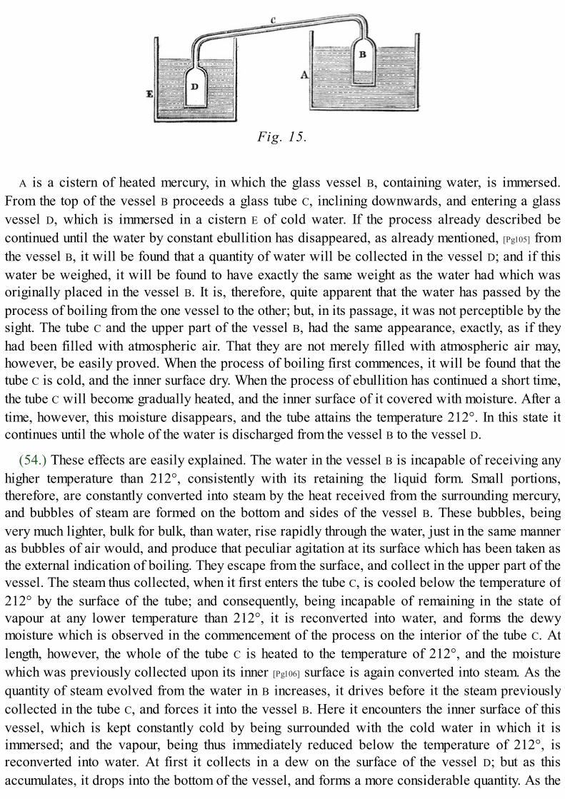
Fig. 15.
A is a cistern of heated mercury, in which the glass vessel B, containing water, is immersed.From the top of the vessel B proceeds a glass tube C, inclining downwards, and entering a glassvessel D, which is immersed in a cistern E of cold water. If the process already described becontinued until the water by constant ebullition has disappeared, as already mentioned, [Pg105] fromthe vessel B, it will be found that a quantity of water will be collected in the vessel D; and if thiswater be weighed, it will be found to have exactly the same weight as the water had which wasoriginally placed in the vessel B. It is, therefore, quite apparent that the water has passed by theprocess of boiling from the one vessel to the other; but, in its passage, it was not perceptible by thesight. The tube C and the upper part of the vessel B, had the same appearance, exactly, as if theyhad been filled with atmospheric air. That they are not merely filled with atmospheric air may,however, be easily proved. When the process of boiling first commences, it will be found that thetube C is cold, and the inner surface dry. When the process of ebullition has continued a short time,the tube C will become gradually heated, and the inner surface of it covered with moisture. After atime, however, this moisture disappears, and the tube attains the temperature 212°. In this state itcontinues until the whole of the water is discharged from the vessel B to the vessel D.
(54.) These effects are easily explained. The water in the vessel B is incapable of receiving anyhigher temperature than 212°, consistently with its retaining the liquid form. Small portions,therefore, are constantly converted into steam by the heat received from the surrounding mercury,and bubbles of steam are formed on the bottom and sides of the vessel B. These bubbles, beingvery much lighter, bulk for bulk, than water, rise rapidly through the water, just in the same manneras bubbles of air would, and produce that peculiar agitation at its surface which has been taken asthe external indication of boiling. They escape from the surface, and collect in the upper part of thevessel. The steam thus collected, when it first enters the tube C, is cooled below the temperature of212° by the surface of the tube; and consequently, being incapable of remaining in the state ofvapour at any lower temperature than 212°, it is reconverted into water, and forms the dewymoisture which is observed in the commencement of the process on the interior of the tube C. Atlength, however, the whole of the tube C is heated to the temperature of 212°, and the moisturewhich was previously collected upon its inner [Pg106] surface is again converted into steam. As thequantity of steam evolved from the water in B increases, it drives before it the steam previouslycollected in the tube C, and forces it into the vessel B. Here it encounters the inner surface of thisvessel, which is kept constantly cold by being surrounded with the cold water in which it isimmersed; and the vapour, being thus immediately reduced below the temperature of 212°, isreconverted into water. At first it collects in a dew on the surface of the vessel D; but as thisaccumulates, it drops into the bottom of the vessel, and forms a more considerable quantity. As the

quantity of water is observed to be gradually diminished in the vessel B, the quantity will be foundto be gradually increased in the vessel D; and if the operation be suspended at any stage of theprocess, and the water in the two vessels weighed, it will be found that the weight of the water inD is exactly equal to the weight which the water in B has lost.
(55.) The demonstration is, therefore, perfect, that the gradual diminution of the boiling water inthe vessel B is produced by the conversion of that water into steam by the heat. In the process firstdescribed, when the top of the vessel B was supposed to be open, this steam made its escape intothe air, where it was first dispersed, and subsequently cooled in separate particles, and wasdeposited in minute globules of moisture on the ground and on surrounding objects.
(56.) In reviewing this process, we are struck by the fact, that the continued application of heatto the vessel B is incapable of raising the temperature of the water contained in it above 212°. Thispresents an obvious analogy to the process of liquefaction, and leads to inquiries of a similarnature, which are attended with a like result. We must either infer, that the water, having arrived at212°, received no more heat from the mercury; or that such heat, if received, is incapable ofaffecting the thermometer; or, finally, that the steam which passes off carries this heat with it. Thatthe water receive heat from the mercury, will be proved by the fact, that, if the vessel B beremoved from the mercury, other things remaining as before, the temperature of the mercury willrapidly rise, and if the fire be continued, it will even boil; but so long as the [Pg107] vessel B remainsimmersed, it prevents the mercury from increasing in temperature. It therefore receives that heatwhich would otherwise raise the temperature of the quicksilver.
Fig. 16.
If a thermometer be immersed in the steam which collects in the upper part of the vessel B, itwill show the same temperature (of 212°) as the water from which it is raised. The heat, therefore,received from the mercury, is clearly not imparted in a sensible form to the steam, which has thesame temperature in the form of steam as it had in the form of water. What has been alreadyexplained respecting liquefaction would lead us, by analogy, to suspect that the heat imparted bythe mercury to the water has become latent in the steam, and is instrumental to the conversion ofwater into steam, in the same manner as heat has been shown to be instrumental to the conversionof ice into water. As the fact was in that case detected by mixing ice with water, so we shall, in thepresent instance, try it by a like test, viz. by mixing water with steam. Let about five ounces and ahalf of water, at the temperature of 32°, be placed in a vessel A (fig. 16.), and let another vessel B,in which water is kept constantly boiling at the temperature of 212°, communicate with A by a pipeC proceeding from the top, so that the steam may be conducted from B, and escape from the mouthof the pipe at some depth below the surface of the water in A. As the steam issues from the pipe, itwill be immediately reconverted into water by the cold water which it encounters; and, by

continuing this process, the water in A will be gradually heated by the steam combined with it andreceived through the pipe C. If this process be continued until the water in A is raised to thetemperature of 212°, it will boil. Let it then be weighed, and it will be found to weigh six ouncesand a half: from whence we infer, that one ounce of water has been received from the vessel B inthe form of steam, and has been reconverted into water by the inferior temperature of the water inA. Now, this ounce of water received in the form of steam into the vessel A had, when in that form,the temperature of 212°. It is now [Pg108] converted into the liquid form, and still retains the sametemperature of 212°; but it has caused the five ounces and a half of water with which it has beenmixed, to rise from the temperature of 32° to the temperature of 212°,—and this, without losingany temperature itself. It follows, therefore, that, in returning to the liquid state, it has parted withas much heat as is capable of raising five times and a half its own weight of water from 32° to212°. This heat was combined with the steam, though not sensible to the thermometer; and was,therefore, latent. Had it been sensible in the water in B, it would have caused the water to haverisen through a number of thermometric degrees, amounting to five times and a half the excess of212° above 32°; that is, through five times and a half 180°; for it has caused five times and a halfits own weight of water to receive an equal increase of temperature. But five times and a half 180°is 990°, or, to use round numbers (for minute accuracy is not here our object), 1000°. It follows,therefore, that an ounce of water, in passing from the liquid state at 212° to the state of steam at212°, receives as much heat as would be sufficient to raise it through 1000 thermometric degrees,if that heat, instead of becoming latent, had been sensible.
(57.) In order to derive all the knowledge from these experiments which they are capable ofimparting, it will be necessary to examine very carefully how water comports itself under a varietyof different circumstances.
If water be boiled in an open vessel, with a thermometer immersed, on different days, it will beobserved that the fixed temperature which it assumes in boiling will be subject to a variationwithin certain small limits. Thus, at one time, it will be found to boil at the temperature of 210°;while, at others, the thermometer immersed in it will rise to 213°; and, on different occasions, itwill fix itself at different points within these limits. It will also be found, if the same experiment beperformed at the same time in distant places, that the boiling points will be subject to a likevariation. Now, it is natural to inquire what cause produces this variation; and we shall be led tothe discovery of the cause, by examining what other physical effects undergo a simultaneouschange. [Pg109]
If we observe the height of the barometer at the time of making each experiment, we shall find avery remarkable correspondence between it and the boiling temperature. Invariably, whenever thebarometer stands at the same height, the boiling temperature will be the same. Thus, if thebarometer stands at 30 inches, the boiling temperature will be 212°. If the barometer fall to 291⁄2inches, the thermometer stands at a small fraction above 211°. If the barometer rise to 301⁄2 inches,the boiling temperature rises to nearly 213°. The variation in the boiling temperature is, then,accompanied by a variation in the pressure of the atmosphere indicated by the barometer; and it isconstantly found that the boiling point will remain unchanged, so long as the atmospheric pressureremains unchanged, and that every increase in the one causes a corresponding increase in the other.
(58.) From these facts it must be inferred, that the pressure excited on the surface of the waterhas a tendency to resist its ebullition, and to make it necessary, before it can boil, that it should
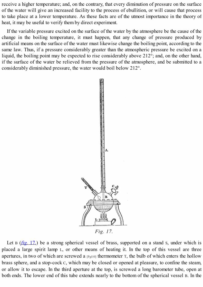
receive a higher temperature; and, on the contrary, that every diminution of pressure on the surfaceof the water will give an increased facility to the process of ebullition, or will cause that processto take place at a lower temperature. As these facts are of the utmost importance in the theory ofheat, it may be useful to verify them by direct experiment.
If the variable pressure excited on the surface of the water by the atmosphere be the cause of thechange in the boiling temperature, it must happen, that any change of pressure produced byartificial means on the surface of the water must likewise change the boiling point, according to thesame law. Thus, if a pressure considerably greater than the atmospheric pressure be excited on aliquid, the boiling point may be expected to rise considerably above 212°; and, on the other hand,if the surface of the water be relieved from the pressure of the atmosphere, and be submitted to aconsiderably diminished pressure, the water would boil below 212°.
Fig. 17.
Let B (fig. 17.) be a strong spherical vessel of brass, supported on a stand S, under which isplaced a large spirit lamp L, or other means of heating it. In the top of this vessel are threeapertures, in two of which are screwed a [Pg110] thermometer T, the bulb of which enters the hollowbrass sphere, and a stop-cock C, which may be closed or opened at pleasure, to confine the steam,or allow it to escape. In the third aperture at the top, is screwed a long barometer tube, open atboth ends. The lower end of this tube extends nearly to the bottom of the spherical vessel B. In the
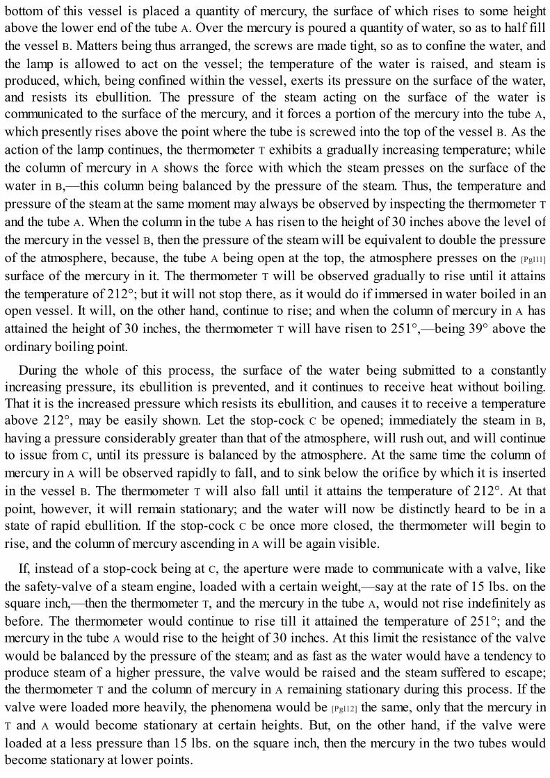
bottom of this vessel is placed a quantity of mercury, the surface of which rises to some heightabove the lower end of the tube A. Over the mercury is poured a quantity of water, so as to half fillthe vessel B. Matters being thus arranged, the screws are made tight, so as to confine the water, andthe lamp is allowed to act on the vessel; the temperature of the water is raised, and steam isproduced, which, being confined within the vessel, exerts its pressure on the surface of the water,and resists its ebullition. The pressure of the steam acting on the surface of the water iscommunicated to the surface of the mercury, and it forces a portion of the mercury into the tube A,which presently rises above the point where the tube is screwed into the top of the vessel B. As theaction of the lamp continues, the thermometer T exhibits a gradually increasing temperature; whilethe column of mercury in A shows the force with which the steam presses on the surface of thewater in B,—this column being balanced by the pressure of the steam. Thus, the temperature andpressure of the steam at the same moment may always be observed by inspecting the thermometer Tand the tube A. When the column in the tube A has risen to the height of 30 inches above the level ofthe mercury in the vessel B, then the pressure of the steam will be equivalent to double the pressureof the atmosphere, because, the tube A being open at the top, the atmosphere presses on the [Pg111]
surface of the mercury in it. The thermometer T will be observed gradually to rise until it attainsthe temperature of 212°; but it will not stop there, as it would do if immersed in water boiled in anopen vessel. It will, on the other hand, continue to rise; and when the column of mercury in A hasattained the height of 30 inches, the thermometer T will have risen to 251°,—being 39° above theordinary boiling point.
During the whole of this process, the surface of the water being submitted to a constantlyincreasing pressure, its ebullition is prevented, and it continues to receive heat without boiling.That it is the increased pressure which resists its ebullition, and causes it to receive a temperatureabove 212°, may be easily shown. Let the stop-cock C be opened; immediately the steam in B,having a pressure considerably greater than that of the atmosphere, will rush out, and will continueto issue from C, until its pressure is balanced by the atmosphere. At the same time the column ofmercury in A will be observed rapidly to fall, and to sink below the orifice by which it is insertedin the vessel B. The thermometer T will also fall until it attains the temperature of 212°. At thatpoint, however, it will remain stationary; and the water will now be distinctly heard to be in astate of rapid ebullition. If the stop-cock C be once more closed, the thermometer will begin torise, and the column of mercury ascending in A will be again visible.
If, instead of a stop-cock being at C, the aperture were made to communicate with a valve, likethe safety-valve of a steam engine, loaded with a certain weight,—say at the rate of 15 lbs. on thesquare inch,—then the thermometer T, and the mercury in the tube A, would not rise indefinitely asbefore. The thermometer would continue to rise till it attained the temperature of 251°; and themercury in the tube A would rise to the height of 30 inches. At this limit the resistance of the valvewould be balanced by the pressure of the steam; and as fast as the water would have a tendency toproduce steam of a higher pressure, the valve would be raised and the steam suffered to escape;the thermometer T and the column of mercury in A remaining stationary during this process. If thevalve were loaded more heavily, the phenomena would be [Pg112] the same, only that the mercury inT and A would become stationary at certain heights. But, on the other hand, if the valve wereloaded at a less pressure than 15 lbs. on the square inch, then the mercury in the two tubes wouldbecome stationary at lower points.

(59.) These experiments show that every increase of pressure above the ordinary pressure of theatmosphere causes an increase in the temperature at which water boils. We shall now inquirewhether a diminution of pressure will produce a corresponding effect on the boiling point.
This may be easily accomplished by the aid of an air pump. Let water at the temperature of 200°be placed in a glass vessel under the receiver of an air pump, and let the air be graduallywithdrawn. After a few strokes of the pump, the water will boil; and if the mercurial gauge of thepump be observed, it will be found that its altitude will be about 231⁄2 inches. Thus the pressure towhich the water is submitted has been reduced from the ordinary pressure of the atmosphereexpressed by the column of 30 inches of mercury, to a diminished pressure expressed by 231⁄2inches; and we find that the temperature at which the water boils has been lowered from 212° to200°. Let the same experiment be repeated with water at the temperature of 180°, and it will befound that a further rarefaction of the air is necessary, but the water will at length boil. If the gaugeof the pump be now observed, it will be found to stand at about fifteen inches, showing, that at thetemperature of 180° water will boil under half the ordinary pressure of the atmosphere. Theseexperiments may be varied and repeated; and it will be always found, that, as the pressure isdiminished or increased, the temperature at which the water will boil will be also diminished orincreased.
(60.) The same effects may be exhibited in a striking manner without an air pump, by producinga vacuum by the condensation of steam. Let a small quantity of water be placed in a thin glassflask, and let it be boiled by holding it over a spirit lamp. When the steam is observed to issueabundantly from the mouth of the flask, let it be quickly corked and removed from the lamp. Theprocess of boiling will then cease, and the water will become quiescent; but if the flask be plunged[Pg113] in a vessel of cold water, the water it contains will again pass into a state of violentebullition, thus exhibiting the singular fact of water being boiled by cooling it. This effect isproduced by the cold medium in which the flask is immersed, causing the steam above the surfaceof the water in it to be condensed, and therefore relieving the water from its pressure. The water,under these circumstances, boils at a lower temperature than when submitted to the pressure of theuncondensed vapour.
(61.) There is no limit to the temperature to which water may be raised, if it be submitted to asufficient pressure to resist its tendency to take the vaporous form. If a strong metallic vessel benearly filled with water, so as to prevent the liquid from escaping by any force which it can exert,the water thus inclosed may be heated to any temperature whatever without boiling; in fact, it maybe made red-hot; and the temperature to which it may be raised will have no limit, except thestrength of the vessel containing it, or the point at which the metal of which it is formed may beginto soften or to be fused.
(62.) The following table will show the temperature at which water will boil under differentpressures of the atmosphere corresponding to the altitudes of the barometer between 26 and 31inches.
Barometer.inches
BoilingPoint.
26 204°·9126·5 205°·7927 206°·6727·5 207°·55

28 208°·4328·5 209°·3129 210°·1929·5 211°·0730 212° 30·5 212°·8831 213°·76
From this table it appears, that, for every tenth of an inch which the barometric column variesbetween these limits, the boiling temperature changes by the fraction of a degree expressed by thedecimal ·176, or nearly by the vulgar fraction 1⁄6.
(63.) In the experiment already described, by which the latent [Pg114] heat of steam wasdetermined, the water was supposed to be boiled under the ordinary pressure of the atmosphere.Having seen, however, that water may boil at different temperatures, under different pressures, theinquiry presents itself, whether the heat absorbed in vaporisation at different temperatures, andunder different pressures, is subject to any variation? Experiments of the same nature as thosealready described, instituted upon water in a state of ebullition at different temperatures, as wellbelow as above 212°, have led to the discovery of a very remarkable fact in the theory of vapour.It has been found that the heat absorbed by vaporisation is always less, the higher the temperatureat which the ebullition takes place; and less, by the same amount as the temperature of ebullition isincreased. Thus, if water boil at 312°, the heat absorbed in ebullition will be less by 100° than if itboiled at 212°; and again, if water be boiled under a diminished pressure, at 112°, the heatabsorbed in vaporisation will be 100° more than the heat absorbed by water boiled at 212°. Itfollows, therefore, that the actual consumption of heat in the process of vaporisation must be thesame, whatever be the temperature at which the vaporisation takes place; for whatever heat issaved in the sensible form, is consumed in the latent form, and vice versâ.
Let us suppose a given weight of water at the temperature of 32° to be exposed to any regularsource by which heat may be supplied to it. If it be under the ordinary atmospheric pressure, thefirst 180° of heat which it receives will raise it to the boiling point, and the next 1000° willconvert it into steam. Thus, in addition to the heat which it contains at 32°, the steam at 212°contains 1180° of heat. But if the same water be submitted to a pressure equal to half theatmospheric pressure, then the first 148° of heat which it receives will cause it to boil, and the next1032° will convert it into vapour. Thus, steam at the temperature of 180° contains a quantity ofheat more than the same quantity of water at 32°, by 1032° added to 148°, which gives a sum of1180°. Steam, therefore, raised under the ordinary pressure of the atmosphere at 212°, and steamraised under half that pressure at 180°, contain the same quantity of heat,—with this difference[Pg115] only—that the one has more latent heat, and less sensible heat, than the other.
From this fact, that the sum of the latent and sensible heats of the vapour of water is constant, itfollows that the same quantity of heat is necessary to convert a given weight of water into steam, atwhatever temperature, or under whatever pressure, the water may be boiled. It follows, also, that,in the steam engine, equal weights of high-pressure and low-pressure steam are produced by thesame consumption of fuel; and that, in general, the consumption of fuel is proportional to thequantity of water vaporised, whatever the pressure of the steam may be.[18]
(64.) Having explained the conditions under which, by supplying heat to water, it is convertedinto steam, and, by abstracting heat from steam, it may be reconverted into water, let us now

consider the mechanical force which is developed in these phenomena.
Fig. 18.
Let A B (fig. 18.) be a tube, or cylinder, the base of which is equal to a square inch, and let apiston P move in it so as to be steam-tight. Let it be supposed, that under this piston there is, in thebottom of the cylinder, a cubic inch of water between the bottom of the piston and the bottom of thetube; let the piston be counterbalanced by a weight W acting over a pulley, which will be justsufficient to counterpoise the weight of the piston, so as leave no force tending to keep the pistondown, except the force of the atmosphere acting above it. Under the circumstances here supposed,the piston being in contact with the water, and all air being excluded, it will be pressed down bythe weight of the atmosphere, which we will suppose to be fifteen pounds, the magnitude of thepiston being a square inch. [Pg116]
Now let the flame of a lamp be applied at the bottom of the tube; the water under the pistonhaving its temperature thereby gradually raised, and being submitted to no pressure save that of theatmosphere above the piston, it will begin to be converted into steam when it has attained thetemperature of 212°. According as it is converted into steam, it will cause the piston to ascend inthe tube until all the water has been evaporated. If the tube were constructed of sufficient length,the piston then would be found to have risen to the height of about seventeen hundred inches, orone hundred and forty-two feet; since, as has been already explained, water passing into steamunder the ordinary pressure of the atmosphere undergoes an increase of bulk in the proportion ofabout seventeen hundred to one.
Now in this process, the air above the piston, which presses on it with a force equal to fifteenpounds, has been raised one hundred and forty-two feet. It appears, therefore, that, by theevaporation of a cubic inch of water under a pressure equal to fifteen pounds per square inch, amechanical force of this amount is developed.
It is evident that fifteen pounds raised one hundred and forty-two feet successively, is equivalentto one hundred and forty-two times fifteen pounds raised one foot. Now, one hundred and forty-two

times fifteen is two thousand one hundred and thirty, and therefore the force thus obtained is equalto two thousand one hundred and thirty pounds raised one foot high. This being within about 110pounds of a ton, it may be stated, in round numbers, that, by the evaporation of a cubic inch ofwater under these circumstances, a force is obtained equal to that which would raise a ton weight afoot high.
The augmentation of volume which water undergoes in passing into steam under the pressurehere supposed, may be easily retained in the memory, from the accidental circumstance that a cubicinch of water is converted into a cubic foot of steam, very nearly. A cubic foot contains onethousand seven hundred and twenty-eight cubic inches,—which is little different from theproportion which steam bears to water, when raised under the atmospheric pressure. [Pg117]
(65.) It will, therefore, be an advantage to retain in memory the following general facts:—
1. A cubic inch of water evaporated under the ordinary atmospheric pressure, is convertedinto a cubic foot of steam.
2. A cubic inch of water evaporated under the atmospheric pressure, gives a mechanical forceequal to what would raise about a ton weight a foot high.
(66.) Let us, again, suppose the piston P (fig. 23.) to be restored to its original position, with theliquid water beneath it; and, in addition to the weight of the atmosphere which before pressed itdown, let us suppose another weight of fifteen pounds laid upon it, so that the water below shall bepressed by double the weight of the atmosphere. If the lamp were now applied, and at the sametime a thermometer were immersed in the water, it would be found that the water would not beginto be converted into steam until it attained the temperature of about 250°. The piston would thenbegin, as before, to ascend, and the water to be gradually converted into vapour. The water beingcompletely evaporated, it would be found that the piston would be raised to a height little morethan half its former height, or 72 feet. The mechanical effect, therefore, thus obtained, will beequivalent to double the former weight raised half the former height.
In like manner, if the piston were loaded with thirty pounds in addition to the atmosphere, thewhole pressure on the water being then three times the pressure first supposed, the piston would beraised to somewhat more than one third of its first height by the evaporation of the water. Thiswould give a mechanical force equivalent to three times the original weight raised a little morethan one third of the original height.
In general, as the pressure on the piston is increased, the height to which the piston would beraised by the evaporation of the water will be diminished in a proportion somewhat less than theproportion in which the pressure on the piston is increased. If the temperature at which the water isconverted into steam under these different pressures were the same, then the height to which thepiston would be raised by the evaporation of the water would be diminished in precisely [Pg118] thesame proportion as the pressure on the piston is increased; and, in that case, the whole mechanicalforce developed by the evaporation of the water would remain exactly the same under whateverpressure the water might be boiled. We shall explain hereafter the extent to which the variation oftemperature in the water and steam corresponding to the variation of pressure modifies this law;but, as the effect of the difference of temperatures is not considerable, it will be convenient toregister in the memory the following important practical conclusion:—
(67.) A cubic inch of water converted into steam will supply a mechanical force very nearly

equal to a ton weight raised a foot high; and this force will not be subject to considerablevariation, whatever be the temperature or pressure at which the water may be evaporated.
GLASGOW.

FOOTNOTES:[18] The preceding paragraphs, and some other parts of the present volume on the general properties of Heat, are taken
from my Treatise on Heat, in the Cabinet Cyclopœdia, to which those who desire more detailed explanation andmore copious illustration should refer.
GLASGOW COLLEGE.

CHAP. V.
[Pg119]
TOC INX
WATT FINDS THAT CONDENSATION IN THE CYLINDER IS INCOMPATIBLE WITH A DUE ECONOMY OF FUEL.—CONCEIVES THE NOTION OF CONDENSING OUT OF THE CYLINDER.—DISCOVERS SEPARATECONDENSATION.—INVENTS THE AIR-PUMP.—SUBSTITUTES STEAM PRESSURE FOR ATMOSPHERICPRESSURE.—INVENTS THE STEAM CASE, OR JACKET.—HIS FIRST EXPERIMENTS TO REALISE THESEINVENTIONS.—HIS EXPERIMENTAL APPARATUS.—DIFFICULTIES OF BRINGING THE IMPROVEDENGINES INTO USE.—WATT PRACTISES AS A CIVIL ENGINEER.—HIS PARTNERSHIP WITH ROEBUCK.—HIS FIRST PATENT.—DESCRIPTION OF HIS SINGLE-ACTING STEAM ENGINE.
(68.) At the period to which we have now brought the history of the invention of the steam engine,Watt had obtained, chiefly by his own experiments, a sufficient knowledge of the phenomena whichhave been just explained, to enable him to arrive at the conclusion that a very small proportion ofthe whole mechanical effect attending the evaporation was really rendered available by theatmospheric engine; and that, [Pg120] therefore, extensive and injurious sources of waste existed inits machinery.
He perceived that the principal source of this wasteful expenditure of power consisted in thequantity of steam which was condensed at each stroke of the piston, in heating the cylinderprevious to the ascent of the piston. Yet, as it was evident that that ascent could not beaccomplished in a cold cylinder, it was apparent that this waste of power must be inevitable,unless some expedient could be devised, by which a vacuum could be maintained in the cylinder,without cooling it. But, to produce such a vacuum, the steam must be condensed; and, to condensethe steam, its temperature must be lowered to such a point that the vapour proceeding from it shallhave no injurious pressure; yet, if condensed steam be contained in a cylinder at a hightemperature, it will return to the temperature of the cylinder, recover its elasticity, and resist thedescent of the piston.
Having reflected on these circumstances, it became apparent to Watt, that a vice was inherent inthe structure of the atmospheric engine, which rendered a large waste of power inevitable; thisvice arising from the fact, that the condensation of the steam was incompatible with the conditionof maintaining the elevated temperature of the cylinder in which that condensation took place. Itfollowed, therefore, either that the steam must be imperfectly condensed, or that the condensationcould not take place in the cylinder. It was in 1765, that, pondering on these circumstances, thehappy idea occurred to him, that the production of a vacuum could be equally effected, though theplace where the condensation of the steam took place were not the cylinder itself. He saw, that if avessel in which a vacuum was produced were put into communication with another containing anelastic fluid, the elastic fluid would rush into the vacuum, and diffuse itself through the twovessels; but if, on rushing into such vacuum, this elastic fluid, being vapour, were there condensed,or restored to the liquid form, that then the space within the two vessels would be equally rendereda vacuum;—that, under such circumstances, one of the vessels might be maintained at anytemperature, however high, while [Pg121] the other might be kept at any temperature, however low.This felicitous conception formed the first step in that splendid career of invention and discoverywhich has conferred immortality on the name of Watt. He used to say, that the moment the idea ofseparate condensation occurred to him,—that is, of condensing, in one vessel kept cold, the steam

coming from another vessel kept hot,—all the details of his improved engine rushed into his mindin such rapid succession, that, in the course of a day, his invention was so complete that heproceeded to submit it to experiment.
Fig. 19.
To explain the first conception of this memorable invention; let a tube or pipe, S (fig. 19.), beimagined to proceed from the bottom of the cylinder A B to a vessel, C, having a stop-cock, D, bywhich the communication between the cylinder and the vessel C may be opened or closed atpleasure. If we suppose the piston P at the top of the cylinder, and the space below it filled withsteam, the cylinder and steam being at the usual temperature, while the vessel C is a vacuum, andmaintained at a low temperature. Then, on opening the cock D, the steam will rush from thecylinder A B through the tube S, and, passing into the cold vessel C, will be condensed by contactwith its cold sides. This process of condensation will be rendered instantaneous if a jet of coldwater is allowed to play in the vessel C. When the steam thus rushing into C, has been destroyed,and the space in the cylinder A B becomes a vacuum, then the pressure of the atmosphere beingunobstructed, the piston will descend with the force due to the excess of the pressure of theatmosphere above the friction. When it has descended, suppose the stop-cock D closed, and steamadmitted from [Pg122] the boiler through a proper cock or valve below the piston, the cylinder andpiston being still at the same temperature as before. The steam on entering the cylinder, not beingexposed to contact with any surface below its own temperature, will not be condensed, andtherefore will immediately cause the piston to rise, and the piston will have attained the top of thecylinder when as much steam shall have been supplied by the boiler as will fill the cylinder. Whenthis has taken place, suppose the communication with the boiler cut off, and the cock D once moreopened: the steam will again rush through the pipe S into the vessel C, where encountering the coldsurface and the jet of cold water, it will be condensed, and the vacuum, as before, will beproduced in the cylinder A B; that cylinder still maintaining its temperature, the piston will againdescend, and so the process may be continued.
(69.) Having carried the invention to this point, Watt saw that the vessel C would graduallybecome heated by the steam which would be continually condensed in it. To prevent this, as wellas to supply a constant jet of cold water, he proposed to keep the vessel C submerged in a cisternof cold water, from which a pipe should conduct a jet to play within the vessel, so as to condense

the steam as it would pass from the cylinder.
But here a difficulty presented itself, against which it was necessary to provide. The cold wateradmitted through the jet to condense the steam, mixed with the condensed steam itself, wouldgradually collect in the vessel C, and at length choke it. To prevent this, Watt proposed to put thevessel C in communication with a pump F, which might be wrought by the engine itself, and bywhich the water, which would collect in the bottom of the vessel C, would be constantly drawn off.This pump would be evidently rendered the more necessary, since more or less atmospheric air,always combined with water in its common state, would enter the vessel C by the condensing jet.This air would be disengaged in the vessel C by the heat of the steam condensed therein; and itwould rise through the tube S, and vitiate the vacuum in the cylinder;—an effect which would berendered the more injurious, [Pg123] inasmuch as, unlike steam, this elastic fluid would be incapableof being condensed by cold. The pump F, therefore, by which Watt proposed to draw off the waterfrom the vessel C, might also be made to draw off the air, or the principal part of it.
The vessel C was subsequently called a condenser; and, from the circumstances just adverted to,the pump F has been called the air-pump.
These—namely, the cylinder, the condenser, and the air-pump—were the three principal parts inthe invention, as it first presented itself to the mind of Watt—and even before it was reduced to amodel, or submitted to experiment. But, in addition to these, other two improvements offeredthemselves in the very first stage of its progress.
In the atmospheric engine, the piston was maintained steam-tight in the cylinder by supplying astream of cold water above it, by which the small interstices between the piston and cylinderwould be stopped. It is evident that the effect of this water as the piston descended would be tocool the cylinder, besides which any portion of it which might pass between the piston andcylinder and which would pass below the piston, would boil the moment it would fall into thecylinder, which itself would be maintained at the boiling temperature. This water, therefore, wouldproduce steam, the pressure of which would resist the descent of the piston.
Watt perceived, that even though this inconvenience were removed by the use of oil or tallowupon the piston, still, that as the piston would descend in the cylinder, the cold atmosphere wouldfollow it; and would, to a certain extent, lower the temperature of the cylinder. On the next ascentof the piston, this temperature would have to be again raised to 212° by the steam coming from theboiler, and would entail upon the machine a proportionate waste of power.
If the atmosphere of the engine-house could be kept heated to the temperature of boiling water,this inconvenience would be removed. The piston would then be pressed down by air as hot as thesteam to be subsequently introduced into it. On further consideration, however, it occurred to Wattthat it would be still more advantageous if the cylinder itself could be [Pg124] worked in anatmosphere of steam, having only the same pressure as the atmosphere. Such steam would press thepiston down as effectually as the air would; and it would have the further advantage over air, thatif any portion of it leaked through between the piston and cylinder, it would be condensed, whichcould not be the case with atmospheric air. He therefore determined on surrounding the cylinder byan external casing, the space between which and the cylinder he proposed to be filled with steamsupplied from the boiler. The cylinder would thus be enclosed in an atmosphere of its own,independent of the external air, and the vessel so enclosing it would only require to be a little

larger than the cylinder, and to have a close cover at the top, the centre of which might beperforated with a hole to admit the rod of the piston to pass through, the rod being made smooth,and so fitted to the perforation that no steam should escape between them. This method would beattended also with the advantage of keeping the cylinder and piston always heated, not only insidebut outside; and Watt saw that it would be further advantageous to employ the pressure of steam todrive the piston in its descent instead of the atmosphere, as its intensity or force would be muchmore manageable; for, by increasing or diminishing the heat of the steam in which the cylinder wasenclosed, its pressure might be regulated at pleasure, and it might be made to urge the piston withany force that might be required. The power of the engine would therefore be completely undercontrol, and independent of all variations in the pressure of the atmosphere.

(70.) This was a step which totally changed the character of the machine, and which rendered ita STEAM ENGINE instead of an ATMOSPHERIC ENGINE. Not only was the vacuum below the piston nowproduced by the property of steam, in virtue of which it is reconverted into water by cold; but thepressure which urged the piston into this vacuum was due to the elasticity of steam.
The external cylinder, within which the working cylinder was enclosed, was called THE JACKET,and is still very generally used.
Fig. 20.
(71.) The first experiment in which Watt attempted to [Pg125] realise, on a small scale, hisconceptions, was made in the following manner. The cylinder of the engine was represented by abrass syringe A B (fig. 20.) an inch and a third in diameter, and ten inches in length, to which a topand a bottom of tin plate was fitted. Steam was conveyed by a pipe, S, from a small boiler into thelower end of this syringe, a communication being made with the upper end of the syringe by abranch pipe D. For the greater convenience of the experiment, it was found desirable to invert theposition of the cylinder, so that the steam should press the piston P upwards instead of downwards.The piston-rod R therefore was presented downwards. An eduction pipe E was also inserted in thetop of the cylinder, which was carried to the condenser. The piston-rod was made hollow, orrather a hole was drilled longitudinally through it, and a valve was fitted at its lower end, to carryoff the water produced by the steam, which [Pg126] would be condensed in the cylinder in thecommencement of the process. The condenser used in this experiment operated without injection,the steam being condensed by the contact of cold surfaces. It consisted of two thin pipes F, G of tin,ten or twelve inches in length, and the sixth of an inch in diameter, standing beside each otherperpendicularly, and communicating at the top with the eduction pipe, which was provided with a

valve opening upwards. At the bottom these two pipes communicated with another tube I of aboutan inch in diameter, by a horizontal pipe, having in it a valve, M, opening towards I, fitted with apiston K, which served the office of the air-pump, being worked by the hand. This piston, K, hadvalves in it opening upwards. These condensing pipes and air-pump were immersed in a smallcistern, filled with cold water. The steam was conveyed by the steam-pipe S to the bottom of thecylinder, a communication between the top and bottom of the cylinder being occasionally openedby a cock, C, placed in the branch pipe. The eduction pipe leading to the condenser also had acock, L, by which the communication between the top of the cylinder and the condenser might beopened and closed at pleasure. In the commencement of the operation, the cock N admitting steamfrom the boiler, and the cock L opening a communication between the cylinder and the condenser,and the cock C opening a communication between the top and bottom of the cylinder, being allopen, steam rushed from the boiler, passing through all the pipes, and filling the cylinder. A currentof mixed air and steam was thus produced through the eduction pipe E, through the condensingpipes F and G, and through the air-pump I, which issued from the valve H in the eduction pipe, andfrom the valve in the air-pump piston, all of which opened upwards. The steam also in the cylinderpassed through the hole drilled in the piston-rod, and escaped, mixed with air, through the valve inthe lower end of that rod. This process was continued until all the air in the cylinder, pipes, andcondenser, was blown out, and all these spaces filled with pure steam. The cocks L, C, and N, werethen closed, and the atmospheric pressure closed the valve H and the valves in the air-pump piston.The cold surfaces condensing the steam in [Pg127] the pipes F and G, and in the lower part of the air-pump, a vacuum was produced in these spaces. The cock C being now closed, and the cocks L andN being open, the steam in the upper part of the cylinder rushed through the pipe E into thecondenser, where it was reduced to water, so that a vacuum was left in the upper part of thecylinder. The steam from the boiler passing below the piston, pressed it upwards with such force,that it lifted a weight of eighteen pounds hung from the end of the piston-rod. When the pistonreached the top of the cylinder, the cocks L and N were closed, and the cock C opened. Allcommunication between the cylinder and the boiler, as well as between the cylinder and thecondenser, were now cut off, and the steam in the cylinder circulated freely above and below thepiston, by means of the open tube D. The piston, being subject to equal forces upwards anddownwards, would therefore descend by its own weight, and would reach the bottom of thecylinder. The air-pump piston meanwhile being drawn up, the air and the condensed steam in thetubes F and G were drawn into the air-pump I, through the open horizontal tube at the bottom. Itsreturn was stopped by the valve M. By another stroke of the air-pump, this water and air weredrawn out through valves in the piston, which opened upwards. The cock C was now closed, andthe cocks L and N opened, preparatory to another stroke of the piston. The steam in the upper partof the cylinder rushed, as before, into the tubes F and G, and was condensed by their cold surfaces,while steam from the boiler coming through the pipe S, pressed the piston upwards. The pistonagain ascended with the same force as before, and in the same manner the process was continuallyrepeated.
(72.) The quantity of steam expended in this experimental model in the production of a givennumber of strokes of the piston was inferred from the quantity of water evaporated in the boiler;and on comparing this with the magnitude of the cylinder and the weight raised by the pressure ofthe steam, the contrivance was proved to affect the economy of steam, as far as the imperfect

conditions of such a model could have permitted. A larger model was next constructed, having anouter cylinder, or steam case, surrounding the working cylinder, and [Pg128] the experiments madewith it fully realised Watt's expectations, and left no doubt of the great advantages which wouldattend his invention. The weights raised by the piston proved that the vacuum in the cylinderproduced by the condensation was almost perfect; and he found that when he used water in theboiler which by long boiling had been well cleared of air, the weight raised was not much lessthan the whole amount of the pressure of the steam upon the piston. In this larger model, thecylinder was placed in the usual position, with a working lever and other apparatus similar to thatemployed in the Atmospheric Engine.
(73.) It was in the beginning of the year 1765, Watt being then in the twenty-ninth year of his age,that he arrived at these great discoveries. The experimental models just described, by which hisinvention was first reduced to a rude practical test, were fitted up at a place called Delft House, inGlasgow. It will doubtless, at the first view, be a matter of surprise that improvements of suchobvious importance in the economy of steam power, and capable of being verified by tests sosimple, were not immediately adopted wherever atmospheric engines were used. At the time,however, referred to, Watt was an obscure artisan, in a provincial town, not then arrived at thecelebrity to which it has since attained, and the facilities by which inventions and improvementsbecame public were much less than they have since become. It should also be considered that allgreat and sudden advances in the useful arts are necessarily opposed by the existing interests withwhich their effects are in conflict. From these causes of opposition, accompanied with the usualinfluence of prejudice and envy, Watt was not exempt, and was not therefore likely suddenly torevolutionise the arts and manufactures of the country by displacing the moving powers employedin them, and substituting an engine, the efficacy and power of which depended mainly on physicalprinciples, then altogether new and but imperfectly understood.
Not having the command of capital, and finding it impracticable to inspire those who had, withthe same confidence in the advantages of his invention which he himself felt, he was [Pg129] unableto take any step towards the construction of engines on a large scale. Soon after this, he gave up hisshop in Glasgow, and devoted himself to the business of a Civil Engineer. In this capacity he wasengaged to make a survey of the river Clyde, and furnished an elaborate and valuable Report uponits projected improvements. He was also engaged in making a plan of the canal, by which theproduce of the Monkland Colliery was intended to be carried to Glasgow, and in superintendingthe execution of that work. Besides these, several other engineering enterprises occupied hisattention, among which may be mentioned, the navigable canal across the isthmus of Crinan,afterwards completed by Rennie; improvements proposed in the ports of Ayr, Glasgow, andGreenock; the construction of the bridges at Hamilton, and at Rutherglen; and the survey of thecountry through which the celebrated Caledonian canal was intended to be carried.
"If, forgetful of my duties as the organ of this academy," says M. Arago (whose eloquentobservations on the delays of this great invention, addressed to the assembled members of theNational Institute of France, we cannot forbear to quote), "I could think of making you smile, ratherthan expressing useful truths, I would find here matter for a ludicrous contrast. I would call to yourrecollection the authors, who at our weekly sittings demand with all their might and main (à cor età cris) an opportunity to communicate some little remark—some small reflection—some triflingnote, conceived and written the night before; I would represent them to you cursing their fate, whenaccording to your rules, the reading of their communication is postponed to the next meeting,

although during this cruel week, they are assured that their important communication is depositedin our archives in a sealed packet. On the other hand, I would point out to you the creator of amachine, destined to form an epoch in the annals of the world, undergoing patiently and withoutmurmur, the stupid contempt of capitalists,—conscious of his exalted genius, yet stooping for eightyears to the common labour of laying down plans, taking levels, and all the tedious calculationsconnected with the routine of common engineering. While in this conduct you cannot fail torecognise the serenity, [Pg130] the moderation, and the true modesty of his character, yet suchindifference, however noble may have been its causes, has something in it not altogetherblameless. It is not without reason that society visits with severe reprobation those who withdrawgold from circulation and hoard it in their coffers. Is he less culpable who deprives his country, hisfellow citizens, his age, of treasures a thousand times more precious than the produce of the mine;who keeps to himself his immortal inventions, sources of the most noble and purest enjoyment ofthe mind, who abstains from conferring upon labour those powers, by which would be multipliedin an infinite proportion the products of industry, and by which, with advantage to civilisation andhuman nature, he would smooth away the inequalities of the conditions of man."[19]
(74.) Although Watt was thus attracted by pursuits foreign to his recent investigations respectingthe improvement of steam power, he never lost sight of that object. It was not until the year 1768,three years after his great discoveries, that any step was taken to enable him to carry them intoeffect on a large scale. At that time his friends brought him into communication with Dr. Roebuck,the proprietor of the Carron Iron Works, who rented extensive coal works at Kinneal from theDuchess of Hamilton. Watt was first employed by Roebuck as a civil engineer; but when he madeknown to him the improvements he had projected in the steam engine, Roebuck proposed to takeout a patent for an engine on the principle of the model which had been fitted up at Delft House,and to join Watt in a partnership, for the construction of such engines. Sensible of the advantages tobe derived from the influence of Roebuck, and from his command of capital, Watt agreed to cede tohim two thirds of the advantages to be derived from the invention. A patent was accordingly takenout on the fifth of January, 1769, nearly four years after the invention had been completed; and anexperimental engine on a large scale was constructed by him, and fitted up at Kinneal House. In thefirst trial this machine more than fulfilled Watt's anticipations. Its [Pg131] success was complete. Inthe practical details of its construction, however, some difficulties were still encountered, thegreatest of which consisted in packing the piston, so as to be steam-tight. The principle of the newengine did not admit of water being kept upon the piston, to prevent leakage, as in the old engines;he was therefore obliged to have his cylinders much more accurately bored, and more trulycylindrical, and to try a great variety of soft substances for packing the piston, which would makeit steam-tight without great friction, and maintain it so in a situation perfectly dry, and at thetemperature of boiling water.
While Watt was endeavouring to overcome these and other difficulties, in the construction of themachine, his partner, Dr. Roebuck, became embarrassed, by the failure of his undertaking in theBorrowstowness coal and salt works; and he was unable to supply the means of prosecuting withthe necessary vigour the projected manufacture of the new engines.
The important results of Watt's labours having happily at this time become more publicly known,Mr. Matthew Boulton, whose establishment at Soho, near Birmingham, was at that time the mostcomplete manufactory for metal-work in England, and conducted with unexampled enterprise andspirit, proposed to purchase Dr. Roebuck's interest in the patent. This arrangement was effected in

the year 1773, and in the following year Mr. Watt removed to Soho, where a portion of theestablishment was allotted to him, for the erection of a foundery, and other works necessary torealise his inventions on a grand scale.
The patent which had been granted in 1769 was limited to a period of fourteen years, and wouldconsequently expire about the year 1783. From the small progress which had hitherto been made inthe construction of engines upon the new principle, and from the many difficulties still to beencountered, and the large expenditure of capital which must obviously be incurred before anyreturn could be obtained, it was apparent that unless an extension of the patent right could beobtained, Boulton and Watt could never expect any advantage adequate to the risk of their great[Pg132] enterprise. In the year 1774 an application was accordingly made to parliament for anextension of the patent, which was supported by the testimony of Dr. Roebuck, Mr. Boulton, andothers, as to the merits and probable utility of the invention. An Act was accordingly passed, in1775, extending the term of the patent until the year 1800.
(75.) The following abstract of this Act may not be uninteresting at this time, when theanticipations expressed in it have been so successfully and extensively realised:—
"An Act for vesting in James Watt, engineer, his executors, administrators, and assigns, the soleuse and property of certain steam engines, commonly called fire engines, of his invention,throughout his majesty's dominions, for a limited time:
"And whereas the said James Watt hath employed many years, and a considerable part of hisfortune, in making experiments upon steam engines, commonly called fire engines, with a view toimprove those very useful machines, by which several very considerable advantages over thecommon steam engines are acquired; but upon account of the many difficulties which always arisein the execution of such large and complex machines, and of the long time requisite to make thenecessary trials, he could not complete his intention before the end of the year 1774, when hefinished some large engines as specimens of his construction, which have succeeded, so as todemonstrate the utility of the said invention:
"And whereas, in order to manufacture these engines with the necessary accuracy, and so thatthey may be sold at moderate prices, a considerable sum of money must be previously expended inerecting mills and other apparatus; and as several years and repeated proofs will be requiredbefore any considerable part of the public can be fully convinced of the utility of the invention, andof their interest to adopt the same, the whole term granted by the said letters patent may probablyelapse before the said James Watt can receive an advantage adequate to his labour and invention:
"And whereas, by furnishing mechanical power at much less expense, and in more convenientforms, than has hitherto been done, his engines may be of great utility, in facilitating [Pg133] theoperations in many great works and manufactures of this kingdom; yet it will not be in the power ofthe said James Watt to carry his invention into that complete execution which he wishes, and so asto render the same of the highest utility to the public of which it is capable, unless the term grantedby the said letters patent be prolonged, and his property in the said invention secured for such timeas may enable him to obtain an adequate recompense for his labour, time, and expense:
"To the end, therefore, that the said James Watt may be enabled and encouraged to prosecute andcomplete his said invention, so that the public may reap all the advantages to be derived therefromin their fullest extent: it is enacted,

"That from and after the passing of this Act, the sole privilege and advantage of making,constructing, and selling the said engines hereinbefore particularly described, within the kingdomof Great Britain, and his majesty's colonies and plantations abroad, shall be, and are herebydeclared to be, vested in the said James Watt, his executors, administrators, and assigns, for andduring the term of twenty-five years," &c. &c.
(76.) Thus protected and supported, Watt now directed the whole vigour of his mind to perfectthe practical details of his invention, and the result was, the construction on a large scale of theengine which has since been called his SINGLE ACTING STEAM ENGINE.
It is necessary to recollect, that notwithstanding the extensive and various application of steampower in the arts and manufactures, at the time to which our narrative has now reached, the steamengine had never been employed for any other purpose save that of raising water by workingpumps. The motion, therefore, which was required was merely an upward force, such as wasnecessary to elevate the piston of a pump, loaded with the column of water which it raised. Thefollowing then is a description of the improved engine of Watt, by which such work was proposedto be performed:—

Fig. 21.
In the cylinder represented at C (fig. 21.), the piston P moves steam-tight. It is closed at the top,and the piston [Pg134] rod, being accurately turned, runs in a steam-tight collar, B, furnished with astuffing-box, and is constantly lubricated with melted tallow. A funnel is screwed into the top ofthe cylinder, through which, by opening a stop-cock, melted [Pg135] tallow is permitted from time totime to fall upon the piston within the cylinder, so as to lubricate it, and keep it steam-tight. Twoboxes, A A, called the upper and lower steam boxes, contain valves by which steam from the boilermay be admitted and withdrawn. These steam boxes are connected by a tube of communication T,and they communicate with the cylinder at the top and bottom by short tubes represented in thefigure. The upper steam box A contains one valve, by which a communication with the boiler maybe opened or closed at pleasure. The lower valve box contains two valves. The lower valve I

communicates with the tube T′, leading to the condenser D, which being opened or closed, acommunication is made or cut off at pleasure, between the cylinder C and the condenser D. Asecond valve, or upper valve H, which is represented closed in the figure, may be opened so as tomake a free communication between the cylinder C and the tube T, and by that means between thecylinder C, below the piston and the space above the piston. The condenser D is submerged in acistern of cold water. At the side there enters it a tube, E, governed by a cock, which being openedor closed to any required extent, a jet of cold water may be allowed to play in the condenser, andmay be regulated or stopped, at pleasure. This jet, when playing, throws the water upwards in thecondenser towards the mouth of the tube T′, as water issues from the rose of a watering pot. Thetube S proceeds from the boiler, and terminates in the steam box A, so that the steam supplied fromthe boiler constantly fills that box. The valve G is governed by levers, whose pivots are attached tothe framing of the engine, and is opened or closed at pleasure, by raising or lowering the lever G′.The valve G, when open, will therefore allow steam to pass from the boiler through the short tubeto the top of the piston, and this steam will also fill the tube T. If the lower valve H be closed, itscirculation beyond that point will be stopped; but if the valve H be open, the valve I being closed,then the steam will circulate equally in the cylinder, above and below the piston. If the valve I beopen, then steam will rush through the tube T′ into the condenser; but this escape of the steam willbe [Pg136] stopped, if the valve I be closed. The valve H is worked by the lever H′, and the valve I bythe lever I′.
The valve G is called the upper steam valve, H the lower steam valve, I the exhausting valve,and E the condensing valve.
From the bottom of the condenser D proceeds a tube leading to the air-pump, which is alsosubmerged in the cistern of cold water. In this tube is a valve M, which opens outwards from thecondenser towards the air-pump. In the piston of the air-pump N is a valve which opens upwards.The piston-rod Q of the air-pump is attached to a beam of wood called a plug frame, which isconnected with the working beam by a flexible chain playing on the small arch-head immediatelyover the air-pump. From the top of the air-pump barrel above the piston proceeds a pipe orpassage leading to a small cistern, B, called the hot well. The pipe which leads to this well, issupplied with a valve, K, which opens outwards from the air pump barrel towards the well. Fromthe nature of its construction, the valve M admits the flow of water from the condenser towards theair-pump, but prevents its return; and, in like manner, the valve K admits the flow of water from theupper part of the air-pump barrel into the hot well B, but obstructs its return.
Let us now consider how these valves should be worked in order to move the piston upwardsand downwards with the necessary force. It is in the first place necessary that all the air whichfills the cylinder, the tubes and the condenser shall be expelled. To accomplish this it is onlynecessary to open at once the three valves G, H, and I. The steam then rushing from the boilerthrough the steam-pipe S, and the open valve G will pass into the cylinder above the piston, willfill the tube T, pass through the lower steam valve H, will fill the cylinder C below the piston, andwill pass through the open valve I into the condenser. If the valve E be closed so that no jet shallplay in the condenser, the steam rushing into it will be partially condensed by the cold surfaces towhich it will be exposed; but if the boiler supply it through the pipe S in sufficient abundance, itwill rush with violence through the cylinder and all the passages, and its pressure in the [Pg137]

condenser D, combined with that of the heated air with which it is mixed, will open the valve M,and it will rush through mixed with the air into the air-pump barrel N. It will press the valves in theair-pump piston upwards, and, opening them, will rush through, and will collect in the air-pumpbarrel above the piston. It will then, by its pressure, open the valve K, and will escape into thecistern B.
Throughout this process the steam, which mixed with the air fills the cylinder, condenser andair-pumps will be only partially condensed in the last two, and it will escape mixed with airthrough the valve K, and this process will continue until all the atmospheric air which at first filledthe cylinder, tubes, condenser and air-pump barrel shall be expelled through the valve K, and thesevarious spaces shall be filled with pure steam. When that has happened let us suppose all thevalves closed. In closing the valve I the flow of steam to the condenser will be stopped, and thesteam contained in it will speedily be condensed by the cold surface of the condenser, so that avacuum will be produced in the condenser, the condensed steam falling in the form of water to thebottom. In like manner, and for like reasons, a vacuum will be produced in the air-pump. The valveM, and the valves in the air-pump piston will be closed by their own weight.
By this process, which is called blowing through, the atmospheric air, and other permanentgases, which filled the cylinder, tubes, condenser and air-pump are expelled, and these spaces willbe a vacuum. The engine is then prepared to be started, which is effected in the following manner:—The upper steam valve G is opened, and steam allowed to flow from the boiler through thepassage leading to the top of the cylinder. This steam cannot pass to the bottom of the cylinder,since the lower steam valve H is closed. The space in the cylinder below the piston being thereforea vacuum, and the steam pressing above it the piston will be pressed downwards with acorresponding force. When it has arrived at the bottom of the cylinder the steam valve G must beclosed, and at the same time the valve H opened. The valve I leading to the condenser being alsoclosed, the steam [Pg138] which fills the cylinder above the piston is now admitted to circulatethrough the open valve H below the piston, so that the piston is pressed equally upwards anddownwards by steam, and there is no force to resist its movement save its friction with thecylinder. The weight of the pump rods on the opposite end of the beam being more than equivalentto overcome this the piston is drawn to the top of the cylinder, and pushes before it the steamwhich is drawn through the tube T, and the open valve H, and passes into the cylinder C below thepiston.
When the piston has thus arrived once more at the top of the cylinder, let the valve H be closed,and at the same time the valves G and I opened, and the condensing cock E also opened, so as toadmit the jet to play in the condenser. The steam which fills the cylinder C below the piston, willnow rush through the open valve I into the condenser which has been hitherto a vacuum, and thereencountering the jet, will be instantly converted into water, and a mixture of condensed steam andinjected water will collect in the bottom of the condenser. At the same time, the steam proceedingfrom the boiler by the steam pipe S to the upper steam box A, will pass through the open steamvalve G to the top of the piston, but cannot pass below it because of the lower steam valve H beingclosed. The piston, thus acted upon above by the pressure of the steam, and the space in thecylinder below it being a vacuum, its downward motion is resisted by no force but the friction, andit is therefore driven to the bottom of the cylinder. During its descent the valves G, I, and E
remained open. At the moment it arrives at the bottom of the cylinder, all these three valves are
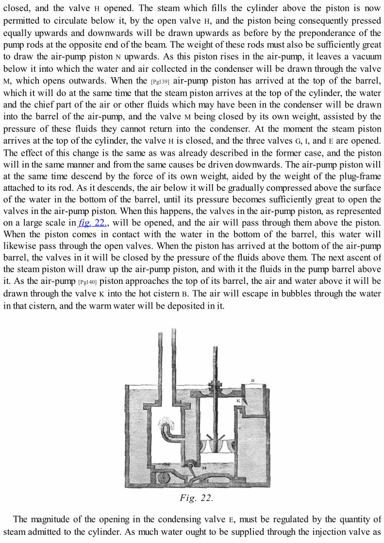
closed, and the valve H opened. The steam which fills the cylinder above the piston is nowpermitted to circulate below it, by the open valve H, and the piston being consequently pressedequally upwards and downwards will be drawn upwards as before by the preponderance of thepump rods at the opposite end of the beam. The weight of these rods must also be sufficiently greatto draw the air-pump piston N upwards. As this piston rises in the air-pump, it leaves a vacuumbelow it into which the water and air collected in the condenser will be drawn through the valveM, which opens outwards. When the [Pg139] air-pump piston has arrived at the top of the barrel,which it will do at the same time that the steam piston arrives at the top of the cylinder, the waterand the chief part of the air or other fluids which may have been in the condenser will be drawninto the barrel of the air-pump, and the valve M being closed by its own weight, assisted by thepressure of these fluids they cannot return into the condenser. At the moment the steam pistonarrives at the top of the cylinder, the valve H is closed, and the three valves G, I, and E are opened.The effect of this change is the same as was already described in the former case, and the pistonwill in the same manner and from the same causes be driven downwards. The air-pump piston willat the same time descend by the force of its own weight, aided by the weight of the plug-frameattached to its rod. As it descends, the air below it will be gradually compressed above the surfaceof the water in the bottom of the barrel, until its pressure becomes sufficiently great to open thevalves in the air-pump piston. When this happens, the valves in the air-pump piston, as representedon a large scale in fig. 22., will be opened, and the air will pass through them above the piston.When the piston comes in contact with the water in the bottom of the barrel, this water willlikewise pass through the open valves. When the piston has arrived at the bottom of the air-pumpbarrel, the valves in it will be closed by the pressure of the fluids above them. The next ascent ofthe steam piston will draw up the air-pump piston, and with it the fluids in the pump barrel aboveit. As the air-pump [Pg140] piston approaches the top of its barrel, the air and water above it will bedrawn through the valve K into the hot cistern B. The air will escape in bubbles through the waterin that cistern, and the warm water will be deposited in it.
Fig. 22.
The magnitude of the opening in the condensing valve E, must be regulated by the quantity ofsteam admitted to the cylinder. As much water ought to be supplied through the injection valve as

will be sufficient to condense the steam contained in the cylinder, and also to reduce thetemperature of the water itself, when mixed with the steam, to a sufficiently low degree to preventit from producing vapour of a pressure which would injuriously affect the working of the piston. Ithas been shown, that five and a half cubic inches of ice-cold water mixed with one cubic inch ofwater in the state of steam would produce six and a half cubic inches of water at the boilingtemperature. If then the cylinder contained one cubic inch of water in the state of steam, and onlyfive and a half cubic inches of water were admitted through the condensing jet, supposing thiswater, when admitted, to be at the temperature of 32°, then the consequence would be that six and ahalf cubic inches of water at the boiling temperature would be produced in the condenser. Steamwould immediately arise from this, and at the same time the temperature of the remaining waterwould be lowered by the amount of the latent heat taken up by the steam so produced. This vapourwould rise through the open exhausting valve I, would fill the cylinder below the piston, andwould impair the efficiency of the steam above pressing it down. The result of the inquiries of Wattrespecting the pressure of steam at different temperatures, showed, that to give efficiency to thesteam acting upon the piston it would always be necessary to reduce the temperature of the waterin the condenser to 100°.
Let us then see what quantity of water at the common temperature would be necessary toproduce these effects.
If the latent heat of steam be taken at 1000°, a cubic inch of water in the state of steam may beconsidered for the purposes of this computation, as equivalent to one cubic inch of water at 1212°.Now the question is, how many cubic inches of water at 60° must be mixed with this, in order thatthe [Pg141] mixture may have the temperature of 100°? This will be easily computed. As the cubicinch of water at 1212° is to be reduced to 100°, it must be deprived of 1112° of its temperature. Onthe other hand, as many inches of water at 60° as are to be added, must be raised in the samemixture to the temperature of 100°, and therefore each of these must receive 40° of temperature.The number of cubic inches of water necessary to be added will therefore be determined byfinding how often 40° are contained in 1112°. If 1112 be divided by 40, the quotient will be 27·8.Hence it appears, that to reduce the water in the condenser to the temperature of 100°, supposingthe temperature of the water injected to be 60°, it will be necessary to supply by the injection cockvery nearly twenty-eight times as much water as passes through the cylinder in the state of steam;and therefore if it be supposed that all the water evaporated in the boiler passes through thecylinder, it follows that about twenty-eight times as much water must be thrown into the condenseras is evaporated in the boiler.
From these circumstances it will be evident that the cold cistern in which the condenser and air-pump are submerged, must be supplied with a considerable quantity of water. Independently of thequantity drawn from it by the injection valve, as just explained, the water in the cistern itself mustbe kept down to a temperature of about 60°. The interior of the condenser and air-pump beingmaintained by the steam condensed in them at a temperature not less than 100°; the outer surfacesof these vessels consequently impart heat to the water in the cold cistern, and have therefore atendency to raise the temperature of that water. To prevent this, a pump called the cold pump,represented at L in fig. 21., is provided. By this pump water is raised from any convenientreservoir, and driven through proper tubes into the cold cistern. This cold pump is wrought by theengine, the rod being attached to the beam. Water being, bulk for bulk, heavier the lower itstemperature, it follows that the water supplied by the cold pump to the cistern will have a tendency

to sink to the bottom, pressing upwards the warmer water contained in it. A waste-pipe isprovided, by which this [Pg142] water is drained off, and the cistern therefore maintained at thenecessary temperature.
From what has been stated, it is also evident that the hot well B, into which the warm water isthrown by the air-pump, will receive considerably more water than is necessary to feed the boiler.A waste-pipe, to carry off this, is also provided; and the quantity necessary to feed the boiler ispumped up by a small pump, O, the rod of which is attached to the beam, as represented in fig. 21.,and which is worked by the engine. The water raised by this pump is conducted to a reservoir fromwhich the boiler is fed, by means which will be hereafter explained.
We shall now explain the manner in which the machine is made to open and close the valves atthe proper times. By referring to the explanation already given, it will be perceived that at themoment the piston reaches the top of the cylinder, the upper steam valve G must be open, to admitthe steam to press it down; while the exhausting valve I must be opened, to allow the steam to passto the condenser; and the condensing valve E must be opened, to let in the water necessary for thecondensation of the steam; and at the same time the lower steam valve H must be closed, to preventthe passage of the steam which has been admitted through G. The valves G, I, and E must be keptopen, and the valve H kept closed, until the piston arrives at the bottom of the cylinder, when itwill be necessary to close all the three valves, G, I, and E, and to open the valve H, and the sameeffects must be produced each time the piston arrives at the top and bottom of the cylinder. All thisis accomplished by a system of levers, which are exhibited in fig. 21. The pivots on which theselevers play are represented on the framing of the engine, and the arms of the levers G′, H′, and I′,communicating with the corresponding valves G, H, and I, are represented opposite a bar attachedto the rod of the air-pump, called the plug frame. This bar carries certain pegs and detents, whichact upon the arms of the several levers in such a manner that, on the arrival of the beam at theextremities of its play upwards and downwards, the levers are so struck that the valves are openedand closed at the proper [Pg143] times. It is needless to explain all the details of this arrangement. Letit be sufficient, as an example of all, to explain the method of working the upper steam valve G.When the piston reaches the top of the cylinder, a pin strikes the arm of the lever G′, and throws itupwards: this, by means of the system of levers, pulls the arm of the valve G downwards, by whichthe upper steam valve is raised out of its seat, and a passage is opened from the steam pipe to thecylinder. The valve is maintained in this state until the piston reaches the bottom of the cylinder,when the arm G′ is pressed downwards, by which the arm G is pressed upwards, and the valverestored to its seat. By similar methods the levers governing the other three valves, H, I, and E, areworked.
Fig. 23.

Fig. 24.
The valves used in these engines were of the kind called spindle valves. They consisted of a flatcircular plate of bell metal, A B, fig. 23., with a round spindle passing perpendicularly through itscentre, and projecting above and below it. This valve, having a conical form, was fitted veryexactly, by grinding into a corresponding circular conical seat, A B C D, fig. 24., which forms thepassage which it is the office of the valve to open and close. When the valve falls into its seat, itfits the aperture like a plug, so as entirely to stop it. The spindle plays in sockets or holes, oneabove and the other below the aperture which the valve stops; these holes keep the valve in itsproper position, so as to cause it to drop exactly into its place.
In the experimental engine made by Mr. Watt at Kinneal, he used cocks, and sometimes slidingcovers, like the regulator described in the old engines; but these he found very soon to becomeleaky. He was, therefore, obliged to change them for the spindle valves just described, which,being truly [Pg144] ground, and accurately fitted in the first instance, were not so liable to go out oforder. These valves are also called puppet clacks, or button valves.
In the earlier engines constructed by Watt, the condensation was produced by the contact of coldsurfaces, without injection. The reason of rejecting the method of condensing by injection was,doubtless, to avoid the injurious effects of the air, which would always enter the condenser, incombination with the water of condensation, and vitiate the vacuum. It was soon found, however,that a condenser acting by cold surfaces without injection, being necessarily composed of narrowpipes or passages, was liable to incrustation from bad water, by which the conducting power of thematerial of the condenser was diminished; so that, while its outer surface was kept cold by thewater of the cold cistern, the inner surface might, nevertheless, be so warm that a very imperfectcondensation would be produced.

SOHO, BIRMINGHAM.

FOOTNOTES:[19] Eloge, p. 308.
BIRMINGHAM.

CHAP. VI.
[Pg145]
TOC INX
CORRESPONDENCE OF WATT WITH SMEATON.—FAILURE OF CONDENSATION BY SURFACE.—IMPROVEMENTS IN CONSTRUCTION OF PISTON.—METHOD OF PACKING.—IMPROVEMENTS IN BORINGTHE CYLINDERS.—DISADVANTAGES OF THE NEW COMPARED WITH THE OLD ENGINES.—GREATLYINCREASED ECONOMY OF FUEL.—EXPEDIENTS TO FORCE THE NEW ENGINES INTO USE.—CORRESPONDENCE WITH SMEATON.—EFFICIENCY OF FUEL IN THE NEW ENGINES.—DISCOVERY OFTHE EXPANSIVE ACTION OF STEAM.—WATT STATES IT IN A LETTER TO DR. SMALL.—ITS PRINCIPLEEXPLAINED.—MECHANICAL EFFECT RESULTING FROM IT.—COMPUTED EFFECT OF CUTTING OFFSTEAM AT DIFFERENT PORTIONS OF THE STROKE.—PRODUCES A VARIABLE POWER.—EXPEDIENTSFOR EQUALISING THE POWER.—LIMITATION OF THE EXPANSIVE PRINCIPLE IN WATT'S ENGINES.—ITSMORE EXTENSIVE APPLICATION IN THE CORNISH ENGINES.
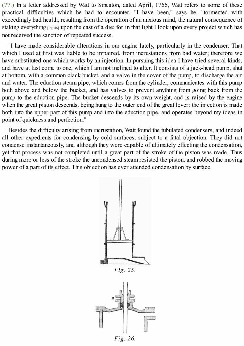
(77.) In a letter addressed by Watt to Smeaton, dated April, 1766, Watt refers to some of thesepractical difficulties which he had to encounter. "I have been," says he, "tormented withexceedingly bad health, resulting from the operation of an anxious mind, the natural consequence ofstaking everything [Pg146] upon the cast of a die; for in that light I look upon every project which hasnot received the sanction of repeated success.
"I have made considerable alterations in our engine lately, particularly in the condenser. Thatwhich I used at first was liable to be impaired, from incrustations from bad water; therefore wehave substituted one which works by an injection. In pursuing this idea I have tried several kinds,and have at last come to one, which I am not inclined to alter. It consists of a jack-head pump, shutat bottom, with a common clack bucket, and a valve in the cover of the pump, to discharge the airand water. The eduction steam pipe, which comes from the cylinder, communicates with this pumpboth above and below the bucket, and has valves to prevent anything from going back from thepump to the eduction pipe. The bucket descends by its own weight, and is raised by the enginewhen the great piston descends, being hung to the outer end of the great lever: the injection is madeboth into the upper part of this pump and into the eduction pipe, and operates beyond my ideas inpoint of quickness and perfection."
Besides the difficulty arising from incrustation, Watt found the tubulated condensers, and indeedall other expedients for condensing by cold surfaces, subject to a fatal objection. They did notcondense instantaneously, and although they were capable of ultimately effecting the condensation,yet that process was not completed until a great part of the stroke of the piston was made. Thusduring more or less of the stroke the uncondensed steam resisted the piston, and robbed the movingpower of a part of its effect. This objection has ever attended condensation by surface.
Fig. 25.
Fig. 26.

(78.) Another source of difficulty arose from the necessity of constructing the piston andcylinder with greater precision than had been usual in the old engines. To fit the cover to thecylinder so as to be steam-tight; to construct the piston rod so as to move through it withoutallowing the escape of steam, and yet at the same time without injurious friction; to connect thepiston rod with the piston, so as to drive the [Pg147] latter through the cylinder with a perfectlystraight and parallel motion; to make such connection perfectly centrical and firm, and yet to allowthe piston in its ascent to come nearly into contact with the cover of the cylinder—were alldifficulties peculiar to the new engine. In the atmospheric engine the shank of the piston rod wasrough and square, and the rod was secured to the piston by two or four branches or stays, asrepresented in fig. 25. It is evident that such a construction would be inadmissible in an engine inwhich the piston in its ascent must be brought nearly into contact with the close cover of thecylinder. Besides this the piston rod of an atmospheric engine might throughout its whole lengthhave any form which was most convenient, and required no other property than the strengthnecessary to work the beam. In the new engine, on the contrary, it was necessary that it should beaccurately turned and finely polished, so as to pass through the hole in the top of the cylinder, andbe maintained in it steam-tight. This was effected by a contrivance called a stuffing-box B,represented in fig. 26. A hole is made in the cover of the cylinder very little greater in magnitudethan the diameter of the piston rod. Above this hole is a cup in which, around the piston, is placeda stuffing of hemp or tow, which is saturated with oil or melted tallow. This collar of hemp ispressed down by another piece, also perforated with a hole through which the piston rod plays,and which is screwed down on the said collar of hemp.
(79.) Although the imperfect manner in which the interior of the cylinders was then formedimpaired the efficiency of the [Pg148] new engines, yet such imperfections were not so injurious as inthe old atmospheric engines. Any imperfection of form of the inner surface of the cylinder wouldnecessarily cause more or less steam or air to escape between the piston and cylinder. In theimproved engine this steam passing into the vacuum below the piston would rush into thecondenser, and be there condensed, so that its effect in resisting the motion of the piston wouldnecessarily be trifling. But on the other hand, any escape of air between the piston and cylinder ofan atmospheric engine would introduce an elastic fluid under the piston, which would injuriouslyaffect the action of the machine.
Fig. 27.
To make the pistons move sufficiently steam-tight in these early imperfect cylinders, Wattcontrived a packing formed of a collar of hemp, or tow, as represented in fig. 27. The bottom ofthe piston was formed of a circular plate of a diameter nearly, but not altogether equal to theinterior diameter of the cylinder. The part of the piston above this was considerably less indiameter, so that the piston was surrounded by a circular groove or channel two inches wide, intowhich hemp or soft rope, called gasket, was run, so as to form the packing. The top of the pistonwas placed over this, having a rim or projecting part, which entered the circular groove and

pressed upon the packing, the cover being pressed downwards by screws passing through thepiston. The lower part of the groove round the piston was rounded with a curve, so that thepressure on the packing might force the latter against the inner surface of the cylinder. This packingwas kept supplied with melted tallow, as already described, from the funnel, screwed into the topof the cylinder. The metallic edges of the piston were by this means prevented from coming intocontact with the surface of the cylinder, which was only pressed upon by the stuffing or packingprojecting beyond these.
(80.) Improved methods of boring soon, however, relieved [Pg149] the engine from a part of theseimperfections, and Watt writes to Mr. Smeaton in the letter above quoted as follows:—
"Mr. Wilkinson has improved the art of boring cylinders; so that I promise, upon a 72 inchcylinder, being not further distant from absolute truth than the thickness of a thin sixpence in theworst part. I am labouring to improve the regulators; my scheme is to make them acute conicalvalves, shut by a weight, and opened by the force of the steam. They bid fair for success, and willbe tried in a few days."
The person here alluded to was Mr. John Wilkinson, of Bersham near Chester, who, about theyear 1775, contrived a new machine for accurately boring the insides of cylinders. The cylinderbeing first obtained from the foundery with a surface as accurate as the process of casting wouldadmit, had its inner surface reduced to still greater accuracy by this machine, which consists of astraight central bar extended along the axis of the cylinder, which was made to revolve slowlyround it. During the operation of boring, the borer or cutter was fitted to slide along this bar, whichbeing perfectly straight, served as a sort of ruler to guide the borer or cutter in its progress throughthe cylinder. In this manner the interior surface of the cylinder was rendered not only true andstraight in its longitudinal direction, but also perfectly circular in its cross section.
The grease found to be most eligible for lubrication was the tallow of beef or mutton; but in theearlier cylinders this was soon consumed by reason of the imperfection of the boring, and thepiston being left dry ceased to be steam-tight. To prevent this, Watt sought for some substance,which while it would thicken the tallow, and detain it around the piston, would not be subject todecomposition by heat. Black lead dust was used for this purpose, but was soon found to wear thecylinder. In the mean while, however, the improved method of boring supplied cylinders whichrendered this expedient unnecessary.
When the inner surface of the cylinder is perfectly true and smooth, the packing of the piston issoon rendered solid and hard, being moulded to the cylinder by working, so as to fit it perfectly.When by wear it became loose, it was [Pg150] only necessary to tighten the screws by which the topand bottom of the piston were held together. The packing being compressed by those means, wasforced outwards towards the surface of the cylinder, so as to be rendered steam-tight.
(81.) It was not until about the year 1778, nine years after the date of the patent, and thirteenafter the invention of separate condensation, that any impression was produced on the mininginterests by the advantages which were presented to them by these vast improvements. This longinterval, however, had not elapsed without considerable advantage; for although all the greatleading principles of the contrivance were invented so early as the year 1765, yet the details ofconstruction had been in a state of progressive and continued improvement from the time Wattjoined Dr. Roebuck, in 1769, to the period now adverted to.
The advantages which the engine offered in the form in which it has been just described, were

numerous and important, as compared even with the most improved form of the atmosphericengine; and it should be remembered, that that machine had also gone on progressively improving,and was probably indebted for some of its ameliorations to hints derived from the labours of Watt,and to the adoption of such of his expedients as were applicable to this imperfect machine, andcould be adopted without an infraction of his patent.
In the most improved forms to which the atmospheric engine had then attained, the quantity ofsteam wasted at each stroke of the piston was equal to the contents of the cylinder. Such engines,therefore, consumed twice the fuel which would be requisite, if all sources of waste could havebeen removed. In Watt's engines, the steam consumed at each stroke of the piston amounted only to11⁄4 times the contents of the cylinder. The waste steam, therefore, per stroke, was only a quarter ofwhat was usefully employed. The absolute waste, therefore, of the best atmospheric engines wasfour times that of the improved engine, and consequently the saving of fuel in the improved enginesamounted to about three eighths of all the fuel consumed in atmospheric engines of the same power.[Pg151]
(82.) But independently of this saving of steam, which would otherwise be wasted, the power ofWatt's engine, as compared with the atmospheric engine, was so much augmented that the formerwould work against a resistance of ten pounds on the square inch under the same circumstances inwhich the latter would not move against more than seven pounds. The cause of this augmentation ofpower is easily explained. In the atmospheric engine the temperature of the condensed steam couldnot be reduced below 152° without incurring a greater loss than would be compensated by theadvantage to be obtained from any higher degree of condensation. Now steam raised from water at152° has a pressure of nearly four pounds per square inch. This pressure, therefore, acted belowthe piston resisting the atmospheric pressure above. In Watt's engine, however, the condenser waskept at a temperature of about 100°, at which temperature steam has a pressure of less than onepound per square inch. A resisting force upon the piston of three pounds per square inch wastherefore saved in Watt's engine as compared with the atmospheric engine.
(83.) Besides these direct sources of economy, there were other advantages incidental to Watt'sengine. An atmospheric engine possessed very limited power of adaptation to a varying load. Themoving power being the atmospheric pressure, was not under control, and, on the other hand, wassubject to variations from day to day and from hour to hour, according to the changes of thebarometer. In the first construction of such an engine, therefore, its power being necessarilyadapted to the greatest load which it would have to move, whenever the load upon its pumps wasdiminished, the motion of the piston in descending would be rapidly accelerated in consequence ofthe moving power exceeding the resistance. By this the machinery would be subject to suddenshocks, which were productive of rapid wear, and exposed the machinery to the danger of fracture.To remedy this inconvenience, the following expedient was provided in the atmospheric engine:whenever the load on the engine was materially diminished, the quantity of water admitted throughthe injection valve to condense the steam was proportionally [Pg152] diminished. An imperfectcondensation being therefore produced, vapour remained in the cylinder under the piston, thepressure of which resisted the atmosphere, and mitigated the force of the machine. Besides this, acock was provided in the bottom of the cylinder, called an air cock, by which atmospheric aircould be admitted to resist the piston whenever the motion was too rapid.
These expedients, however, were all attended with a waste of fuel in relation to the work doneby the engine; for it is evident that the consumption of steam was necessarily the same, whether the

engine was working against its full load or against a reduced resistance.
On the other hand, in the improved engine of Watt, when the load, to work against which theengine exerted its full power, was diminished, a cock or valve was provided in the steam pipeleading from the boiler, which was called a throttle valve, by adjusting which the passage in thatpipe could be more or less contracted. By regulating this cock the supply of steam from the boilerwas checked, and the quantity transmitted to the cylinder diminished, so that its effect upon thepiston might be rendered equal to the amount of the diminished resistance. By this means thequantity of steam transmitted to the cylinder was rendered exactly proportional to the work whichthe engine had to perform. If, under such circumstances, the boiler was worked to its full power, soas to produce steam as fast as it would when the engine was working at full power, then no savingof fuel would be effected, since the surplus steam produced in the boiler would necessarily escapeat the safety valve. But in such case the fireman was directed to limit the fuel of the furnace untilthe discharge at the safety valve ceased.
By these expedients, the actual consumption of fuel in one of these improved engines wasalways in the exact proportion of the work which it performed, whether it worked at full power orat any degree under its regular power.
(84.) Notwithstanding these and other advantages attending the new engines, Boulton and Wattexperienced difficulties all but insurmountable in getting them into use. No manufactory existed inthe country possessing machinery capable of [Pg153] executing with the necessary precision thevalves and other parts which required exact execution, and the patentees were compelled toconstruct machinery at Soho for this purpose; and even after they succeeded in getting the cylindersproperly bored, the piston rods exactly turned and polished, the spindle valves constructed so as tobe steam-tight, and every other arrangement completed which was necessary for the efficiency ofthe machine, the novelty of the engine, and the difficulty which was supposed to attend itsmaintenance in good working order, formed strong objections to its adoption.
To remove such objections, great sacrifices were necessary on the part of Boulton and Watt; andthey accordingly resolved to undertake the construction of the new engines without any profit,giving them to the parties requiring their use at first cost, on the condition of being remunerated bya small share of what they would save in fuel.
"We have no objection," writes Mr. Boulton, "to contract with the Carron Company to direct themaking of an engine to return the water for their mills. * * * * We do not aim at profits inengine building, but shall take our profits out of the saving of fuel; so that if we save nothing, weshall take nothing. Our terms are as follows: we will make all the necessary plans, sections, andelevations for the building, and for the engine with its appurtenances, specifying all cast and forgediron work, and every other particular relative to the engine. We will give all necessary directionsto your workmen, which they must implicitly obey. We will execute, for a stipulated price, thevalves, and all other parts which may·require exact execution, at Soho; we will see that all theparts are put together, and set to work, properly; we will keep our own work in repair for oneyear, and we have no other objection to seven years than the inconvenience of the distance. Wewill guarantee that the engine so constructed shall raise at least 20,000 cubic feet of water twenty-four feet high with each hundred weight of coals burnt.
"When all this is done, a fair and candid comparison shall be made between it, and your ownengine, or any other engine in Scotland, from which comparison the amount of savings in fuel shall
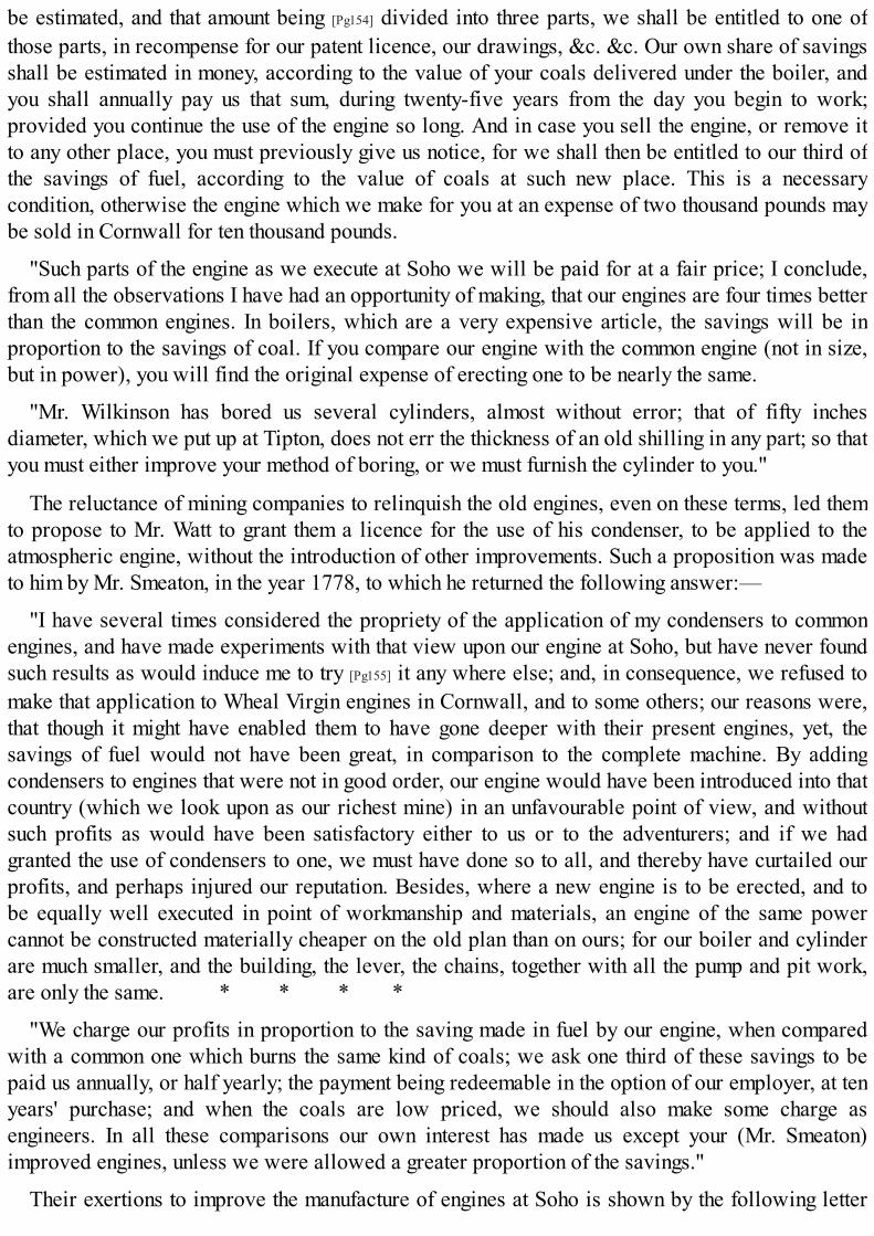
be estimated, and that amount being [Pg154] divided into three parts, we shall be entitled to one ofthose parts, in recompense for our patent licence, our drawings, &c. &c. Our own share of savingsshall be estimated in money, according to the value of your coals delivered under the boiler, andyou shall annually pay us that sum, during twenty-five years from the day you begin to work;provided you continue the use of the engine so long. And in case you sell the engine, or remove itto any other place, you must previously give us notice, for we shall then be entitled to our third ofthe savings of fuel, according to the value of coals at such new place. This is a necessarycondition, otherwise the engine which we make for you at an expense of two thousand pounds maybe sold in Cornwall for ten thousand pounds.
"Such parts of the engine as we execute at Soho we will be paid for at a fair price; I conclude,from all the observations I have had an opportunity of making, that our engines are four times betterthan the common engines. In boilers, which are a very expensive article, the savings will be inproportion to the savings of coal. If you compare our engine with the common engine (not in size,but in power), you will find the original expense of erecting one to be nearly the same.
"Mr. Wilkinson has bored us several cylinders, almost without error; that of fifty inchesdiameter, which we put up at Tipton, does not err the thickness of an old shilling in any part; so thatyou must either improve your method of boring, or we must furnish the cylinder to you."
The reluctance of mining companies to relinquish the old engines, even on these terms, led themto propose to Mr. Watt to grant them a licence for the use of his condenser, to be applied to theatmospheric engine, without the introduction of other improvements. Such a proposition was madeto him by Mr. Smeaton, in the year 1778, to which he returned the following answer:—
"I have several times considered the propriety of the application of my condensers to commonengines, and have made experiments with that view upon our engine at Soho, but have never foundsuch results as would induce me to try [Pg155] it any where else; and, in consequence, we refused tomake that application to Wheal Virgin engines in Cornwall, and to some others; our reasons were,that though it might have enabled them to have gone deeper with their present engines, yet, thesavings of fuel would not have been great, in comparison to the complete machine. By addingcondensers to engines that were not in good order, our engine would have been introduced into thatcountry (which we look upon as our richest mine) in an unfavourable point of view, and withoutsuch profits as would have been satisfactory either to us or to the adventurers; and if we hadgranted the use of condensers to one, we must have done so to all, and thereby have curtailed ourprofits, and perhaps injured our reputation. Besides, where a new engine is to be erected, and tobe equally well executed in point of workmanship and materials, an engine of the same powercannot be constructed materially cheaper on the old plan than on ours; for our boiler and cylinderare much smaller, and the building, the lever, the chains, together with all the pump and pit work,are only the same. * * * *
"We charge our profits in proportion to the saving made in fuel by our engine, when comparedwith a common one which burns the same kind of coals; we ask one third of these savings to bepaid us annually, or half yearly; the payment being redeemable in the option of our employer, at tenyears' purchase; and when the coals are low priced, we should also make some charge asengineers. In all these comparisons our own interest has made us except your (Mr. Smeaton)improved engines, unless we were allowed a greater proportion of the savings."
Their exertions to improve the manufacture of engines at Soho is shown by the following letter

from Mr. Boulton, in the same correspondence to Mr. Smeaton:—
"We are systematising the business of engine making, as we have done before in the buttonmanufactory; we are training up workmen, and making tools and machines to form the differentparts of Mr. Watt's engines with more accuracy, and at a cheaper rate than can possibly be done bythe ordinary methods of working. Our workshop and apparatus will be of [Pg156] sufficient extent toexecute all the engines which are likely to be soon wanted in this country; and it will not be worththe expense for any other engineers to erect similar works, for that would be like building a mill togrind a bushel of corn.
"I can assure you from experience, that our small engine at Soho is capable of raising 500,000cubic feet of water 1 foot high with every 112 lbs. of coals, and we are in hopes of doing muchmore. Mr. Watt's engine has a very great advantage in mines, which are continually workingdeeper: suppose, for instance, that a mine is 50 fathoms deep, you may have an engine which willbe equal to draining the water when the mine is worked, to 100 fathoms deep, and yet you canconstantly adapt the engine to its load, whether it be 50 or 100 fathoms, or any intermediate depth;and the consumption of coals will be less in proportion when working at the lesser than at thegreater depths; supposing it works, as our engines generally do, at 11 lbs. per square inch, whenthe mine becomes 100 fathoms deep."
(85.) The great improvement which has been introduced within the last half century, in thedetails of Watt's steam engine, will be rendered manifest by comparing the effects of a givenweight of fuel here supplied by Mr. Boulton with the effects which the same weight of fuel is nowknown to produce in the best pumping engines worked in Cornwall. One of these engines, in goodworking order, has been known to raise 125,000,000 lbs. 1 foot high, by the combustion of abushel of coals. But the average performance of even the best engines is below this amount. If wetake it at 90,000,000, this will be equivalent to the weight of about 11⁄2 million cubic feet of water,a bushel of coals being 3⁄4 cwt. It will therefore follow that, with the present engines, one hundredweight of coals is capable of raising about two million cubic feet of water one foot high, being aduty four times that assigned to the early engines by Mr. Boulton.
(86.) At the time that Watt, in conjunction with Dr. Roebuck, obtained the patent for hisimproved engine, the idea occurred to him, that the steam which had impelled the piston in itsdescent rushed from the cylinder with a mechanical force much more than sufficient to overcomeany resistance [Pg157] which it had to encounter in its passage to the condenser; and that such forcemight be rendered available as a moving power, in addition to that already obtained from the steamduring the stroke of the piston. This notion involved the whole principle of the expansive action ofsteam, which subsequently proved to be of such importance in the performance of steam engines.Watt was, however, so much engrossed at that time, and subsequently, by the difficulties he had toencounter in the construction of his engines, that he did not attempt to bring this principle intooperation. It was not until after he had organised that part of the establishment at Soho which wasappropriated to the manufacture of steam engines, that he proceeded to apply the expansiveprinciple. Since the date of the patent which he took out for this (1782), was subsequent to theapplication of the same principle by another engineer, named Hornblower, it is right to state, thatthe claim of Mr. Watt to this important step in the improvement of the steam engine, is establishedby a letter addressed by him to Dr. Small, of Birmingham, dated Glasgow, May, 1769:—
"I mentioned to you a method of still doubling the effect of the steam, and that tolerably easy, by

using the power of steam rushing into a vacuum, at present lost. This would do little more thandouble the effect, but it would too much enlarge the vessels to use it all: it is peculiarly applicableto wheel engines, and may supply the want of a condenser, where the force of steam only is used;for open one of the steam valves, and admit steam until one fourth of the distance between it andthe next valve is filled with steam, then shut the valve, and the steam will continue to expand, andto press round the wheel, with a diminishing power, ending in one fourth of its first exertion. Thesum of the series you will find greater than one half, though only one fourth of steam was used. Thepower will indeed be unequal, but this can be remedied by a fly, or by several other means."
In 1776 the engine, which had been then recently erected at Soho, was adapted to act upon theprinciple of expansion. When the piston had been pressed down in the cylinder for a certainportion of the stroke, the further supply of steam [Pg158] from the boiler was cut off, by closing theupper steam valve, and the remainder of the stroke was accomplished by the expansive power ofthe steam which had already been introduced into the cylinder.
(87.) To make this method of applying the force of steam intelligible, some previous explanationof mechanical principles will be necessary.
If a body which offers a certain resistance be urged by a certain moving force, the motion whichit will receive will depend on the relation between the energy of the moving force and the amountof the resistance opposed to it. If the moving force be precisely equal to the resistance, the motionwhich the body will receive will be perfectly uniform.
If the energy of the moving force be greater than the resistance, then its surplus or excess abovethe amount of resistance will be expended in imparting momentum to the mass of the body moved,and the latter will, consequently, continually acquire augmented speed. The motion of the bodywill, therefore, be in this case accelerated.
If the energy of the moving force be less in amount than the resistance, then all that portion of theresistance which exceeds the amount of the moving force will be expended in depriving the massof the body of momentum, and the body will therefore be moved with continually diminished speeduntil it be brought to rest.
(88.) Whenever, therefore, a uniform motion is produced in a body, it may be taken as anindication of the equality of the moving force to the resistance; and, on the other hand, according asthe speed of the body is augmented or diminished, it may be inferred that the energy of the movingforce has been greater or less than the resistance.
It is an error to suppose that rest is the only condition possible for a body to assume when underthe operation of two or more mechanical forces which are in equilibrium. By the laws of motionthe state of a body which is not under the operation of any external force must be either in a state ofrest or of uniform motion. Whichever be its state, it will suffer no change if the body be broughtunder the operation of two or more forces which are in equilibrium; for to suppose [Pg159] suchforces to produce any change in the state of the body, whether from rest to motion, or vice versâ, orin the velocity of the motion which the body may have previously had, would be equivalent to asupposition that the forces applied to the body being in equilibrium were capable of producing adynamical effect, which would be a contradiction in terms. This, though not always clearlyunderstood by mere practical men, or by persons superficially informed, is, in fact, among thefundamental principles of mechanical science.
(89.) When the piston is at the top of the cylinder, and about to commence its motiondownwards, the steam acting upon it will have not only to overcome the resistance arising from thefriction of the various parts of the engine, but will also have to put in motion the whole mass ofmatter of the piston pump rods, pump pistons, and the column of water in the pump barrels.Besides imparting to this mass the momentum corresponding to the velocity with which it will bemoved, it will also have to encounter the resistance due to the preponderance of the weight of thewater and pump rods over that of the steam piston. The pressure of steam, therefore, upon thepiston at the commencement of the stroke must, in accordance with the mechanical principles justexplained, have a greater force than is equal to all the resistances which it would have toovercome, supposing the mass to be moving at a uniform velocity. The moving force, therefore,being greater than the resistance, the mass, when put in motion, will necessarily move with agradually augmented speed, and the piston of the engine which has been described in the lastchapter would necessarily move from the top to the bottom of the cylinder with an acceleratedmotion, having at the moment of its arrival at the bottom a greater velocity than at any other part ofthe stroke. As the piston and all the matter which it has put in motion must at this point come torest, the momentum of the moving mass must necessarily expend itself on some part of themachinery, and would be so much mechanical force lost. It is evident, therefore, independently ofany consideration of the expansive principle, to which we shall presently refer, that the action ofthe [Pg160] moving power in the descent of the piston ought to be suspended before the arrival of thepiston at the bottom of the cylinder, in order to allow the momentum of the mass which is in motionto expend itself, and to allow the piston to come gradually to rest at the termination of the stroke.
Thus, if we were to suppose that after the piston had descended through three fourths of thewhole length of the cylinder, and had acquired a certain velocity, the steam above it were suddenlycondensed, so as to leave a vacuum both above and below it, the piston, being then subject to noimpelling force, would still move downwards, in virtue of the momentum it had acquired, until theresistance would deprive it of that momentum, and bring it to rest; and if the remaining fourth partof the cylinder were necessary for the accomplishment of this, then it is evident that that part of thestroke would be accomplished without further expenditure of the moving power.
In fact, this part of the stroke would be made by the expenditure of that excess of moving power,which, at the commencement of the stroke, had been employed in putting the machinery and its loadin motion, and in subsequently accelerating that motion.
Although under such circumstances the resistance, during the operation of the moving power,shall not have been at any time equal to the moving power, since while the motion was acceleratedit was less, and while retarded greater than that power, yet as the whole moving power has beenexpended upon the resistance, the mechanical effect which the moving power has produced undersuch circumstances will be equal to the actual amount of that power. If in an engine of this kind thesteam was not cut off till the conclusion of the stroke, a part of the moving power would be lostupon those fixed points in the machinery which would sustain the shock produced by theinstantaneous cessation of motion at the end of the stroke.
Independently, therefore, of any consideration of the expansive principle, it appears that, in anengine of this kind, the steam ought to be cut off before the completion of the stroke. [Pg161]

Fig. 28.
(90.) To render the expansive action of steam intelligible, let A B (fig. 28.) represent a cylinderwhose area we will suppose, for the sake of illustration, to be a square foot, and whose length, A
B, shall also be a foot. If steam of a pressure equal to the atmosphere be supplied to this cylinder, itwill exert a pressure of about one ton on the piston; and if such steam be uniformly supplied fromthe boiler, the piston will be moved from A to B with the force of one ton, and that motion will beuniform if the piston be opposed throughout the same space by a resistance equal to a ton. Whenthe piston has arrived at B, let us suppose that the further supply of steam from the boiler is stoppedby closing the upper steam valve, and let us also suppose the cylinder to be continued downwardsso that B C shall be equal to A B, and suppose that B C has been previously in communication withthe condenser, and is therefore a vacuum. The piston at B will then be urged with a force of one tondownwards, and as it descends the steam above it will be diffused through an increased volume,and will consequently acquire a diminished pressure. We shall, for the present, assume that thisdiminution of pressure follows the law of elastic fluids in general; that it will be decreased in thesame proportion as the volume of the steam is augmented. While the piston, therefore, moves fromB downwards it will be urged by a continually decreasing force. Let us suppose, that by someexpedient, it is also subject to a continually decreasing resistance, and that this resistancedecreases in the same proportion as the force which urges the piston. In that case the motion of thepiston would continue uniform. When the piston would arrive at P′, the middle of the secondcylinder, then the space occupied by the steam being increased in the proportion of 2 to 3, thepressure on the piston would be diminished in the proportion of 3 to 2, and the pressure at B beingone ton, it would be two-thirds of a ton at P′. In like manner when the piston would arrive at C, thespace occupied by the steam being double that which [Pg162] it occupied when the piston was at B,the pressure of the steam would be half its pressure at B, and therefore at the termination of thestroke, the pressure on the piston would be half a ton.
If the space from B to C, through which the steam is here supposed to act expansively, be dividedinto ten equal parts, the pressure on the piston at the moment of passing each of those divisionswould be calculated upon the same principle as in the cases now mentioned. After moving throughthe first division, the volume of the steam would be increased in the proportion of 10 to 11, andtherefore its pressure would be diminished in the proportion of 11 to 10. The pressure, therefore,driving the piston at the end of the first of these ten divisions would be 10⁄11ths of a ton. In likemanner, its pressure at the second of the divisions would be 10⁄12ths of a ton, and the third 10⁄13ths of

a ton; and so on, as indicated in the figure.
Now if the pressure of the steam through each of these divisions were to continue uniform, and,instead of gradually diminishing, to suffer a sudden change in passing from one division to another,then the mechanical effect produced from B to C would be obtained by taking a mean or average ofthe several pressures throughout each of the ten divisions. In the present case it has been supposedthat the force on the piston at B was 2240 pounds. To obtain the pressure in pounds correspondingto each of the successive divisions, it will therefore only be necessary to multiply 2240 by 10, andto divide it successively by 11, 12, 13, &c. The pressures, therefore, in pounds, at each of the tendivisions, will be as follows:—
1st 2036·32d 1866·63d 1723·14th 1600·05th 1493·36th 1400·07th 1317·68th 1244·49th 1179·0
10th 1120·0
If the mean of these be taken by adding them together [Pg163] and dividing by 10, it will be foundto be 1498 pounds. It appears, therefore, that the pressures through each of the ten divisions beingsupposed to be uniform (which however, strictly, they are not,) the mechanical effect of the steamfrom B to C would be the same as if it acted uniformly throughout that space upon the piston with aforce of about 1500 pounds, being rather less than three-fourths of its whole effect from A to B.
But it is evident that this principle will be equally applicable if the second cylinder had anyother proportion to the first. Thus it might be twice the length of the first; and in that case, a furthermechanical effect would be obtained from the expansion of the steam.
The more accurate method of calculating the effect of the expansion from B to C, would involvemore advanced mathematical principles than could properly be introduced here; but the result ofsuch a computation would be that the actual average effect of the steam from B to C would be equalto a uniform pressure through that space, amounting to one thousand five hundred and forty-fivepounds, being greater than the result of the above computation, the difference being due to theexpansive action through each of the ten divisions, which was omitted in the above computation.
(91.) It is evident that the expansive principle, as here explained, involves the condition of avariation in the intensity of the moving power. Thus, if the steam act with a uniform energy on thepiston so long as its supply from the boiler continues, the moment that supply is stopped, byclosing the steam valve, the steam contained in the cylinder will fill a gradually increasing volumeby the motion of the piston, and therefore will act above the piston with a gradually decreasingenergy. If the resistance to the moving power produced by the load, friction, &c. be not subject to avariation corresponding precisely to such variation in the moving power, then the consequencemust be that the motion imparted to the load will cease to be uniform. If the energy of the movingpower at any part of the stroke be greater than the resistance, the motion produced will beaccelerated; if it be less, the motion will be retarded; and if it be at one time greater, and another[Pg164] time less, as will probably happen, then the motion will be alternately accelerated and

retarded. This variation in the speed of the body moved will not, however, affect the mechanicaleffect produced by the power, provided that the momentum imparted to the moving mass beallowed to expend itself at the end of the stroke, so that the piston may be brought to rest as nearlyas possible by the resistance of the load, and not by any shock on any fixed points in the machine.This is an object which, consequently, should be aimed at with a view to the economy of power,independently of other considerations connected with the wear and tear of the machinery. So longas the engine is only applied to the operation of pumping water, great regularity of motion is notessential, and, therefore, the variation of speed which appears to be an almost inevitableconsequence of any extensive application of the expansive principle, is of little importance. In thepatent which Watt took out for the application of the expansive principle, he specified severalmethods of producing a uniform effect upon a uniform resistance, notwithstanding the variation ofthe energy of the power which necessarily attended the expansion of the steam. This he proposedto accomplish by various mechanical means, some of which had been previously applied to theequalisation of a varying power. One consisted in causing the piston to act on a lever, whichshould have an arm of variable length, the length increasing in the same proportion as the energy ofthe moving power diminished. This was an expedient which had been already applied inmechanics for the purpose of equalising a varying power. A well-known example of it is presentedin the main-spring and fuzee of a watch. According as the watch goes down, the main-springbecomes relaxed, and its force is diminished; but, at the same time, the chain by which it drives thefuzee acts upon a wheel or circle, having a diameter increased in the same proportion as the energyof the spring is diminished.
Another expedient consisted in causing the moving power, when acting with greatest energy, tolift a weight which should be allowed to descend again, assisting the piston when the energy of themoving force was diminished. [Pg165]
Another method consisted in causing the moving force, when acting with greatest energy, toimpart momentum to a mass of inert matter, which should be made to restore the same force whenthe moving power was more enfeebled. We shall not more than allude here to these contrivancesproposed by Watt, since their application has never been found advantageous in cases where theexpansive principle is used.
(92.) The application of the expansive principle in the engines constructed by Boulton and Watt,was always very limited, by reason of their confining themselves to the use of steam having apressure not much exceeding that of the atmosphere. If the principle of expansion, as aboveexplained, be attentively considered, it will be evident that the extent of its application will mainlydepend on the density and pressure of the steam admitted from the boiler. If the density andpressure be not considerable when the steam is cut off, the extent of its subsequent expansion willbe proportionally limited. It was in consequence of this, that this principle from whichconsiderable economy of power has been derived, was applied with much less advantage by Mr.Watt than it has since been by others, who have adopted the use of steam of much higher pressure.In the engines of Boulton and Watt, where the expansive principle was applied, the steam was cutoff after the piston had performed from one half to two thirds of the stroke, according to thecircumstances under which the engine was worked. The decreasing pressure produced byexpansion was, in this case, especially with the larger class of engines, little more than would benecessary to allow the momentum of the mass moved to spend itself, before the arrival of thepiston at the end of the stroke.

Subsequently, however, boilers producing steam of much higher pressure were applied, and thesteam was cut off when the piston had performed a much smaller part of the whole stroke. Thegreat theatre of these experiments and improvements has been the mining districts in Cornwall,where, instead of working with steam of a pressure not much exceeding that of the atmosphere, ithas been found advantageous to use steam whose pressure is at least four times as great as [Pg166]
that of the atmosphere; and instead of limiting its expansion to the last half or fourth of the stroke, itis cut off after the piston has performed one fourth part of the stroke or less, all the remainder ofthe stroke being accomplished by the expansive power of the steam, and by momentum.

BRIDGE OVER THE CLYDE AT HAMILTON,DESIGNED BY WATT.
DOUBLE-ACTING ENGINE,ZINC WORKS, CITY ROAD, LONDON.

CHAP. VII.
[Pg167]
TOC INX
PROPERTIES OF STEAM.—COMMON STEAM.—SUPERHEATED STEAM.—LAW OF DALTON AND GAY LUSSAC.—LAW OF MARIOTTE.—RELATION BETWEEN TEMPERATURE AND PRESSURE OF COMMON STEAM.—EFFECTS OF THE EXPANSION OF COMMON STEAM.—MECHANICAL EFFECTS OF STEAM.—METHOD OFEQUALISING THE EXPANSIVE FORCE.—HORNBLOWER'S ENGINE.—WOOLF'S ENGINE.—WATT'SATTEMPTS TO EXTEND THE STEAM ENGINE TO MANUFACTURES.—PAPIN'S PROJECTED APPLICATIONSOF THE STEAM ENGINE.—SAVERY'S APPLICATIONS OF THE ENGINE TO MOVE MACHINERY.—JONATHAN HULL'S APPLICATION TO WATER WHEELS.—STEWART'S APPLICATION OF THE ENGINE TOMILL WORK.—WASHBOROUGH'S APPLICATION OF THE FLY WHEEL AND CRANK.—WATT'S SECONDPATENT.—DOUBLE-ACTION VALVES.
(93.) Since the application of the expansive action of steam involves the consideration of itsproperties when it ceases to be in contact with the water from which it was produced, andlikewise the variation of its pressure in different states of [Pg168] density and at differenttemperatures, it is necessary here to explain some of the most important of these properties ofvapour.
Steam may exist in two states, distinguished from each other by the following circumstances:—
1st. It may be such that the abstraction from it of any portion of heat, however small, will causeits partial condensation.
2d. It may be such as to admit of the abstraction of heat from it without undergoing any otherchange than that which air would undergo under like circumstances, viz. a diminution oftemperature and pressure.
(94.) We shall call, for distinction, the former Common Steam, and the latter SuperheatedSteam.
Fig. 29.
To explain the circumstances out of which these properties arise, let B (fig. 29.) be imagined tobe a vessel filled with water, communicating by a pipe and stopcock with another vessel A, whichin the commencement of the process may be conceived to be filled with air. Let D be a pipe and

stopcock at the top of this vessel. If the vessel B be heated, and the two cocks be opened, the steamproceeding from the water in B will blow the air out of the vessel A through the open stopcock D,in the same manner as air is blown from a steam engine. When the vessel A by these means hasbeen filled with pure steam, let both stopcocks be closed. If the steam in A, under thesecircumstances, have a pressure of 15 lbs. per square inch, its temperature will be found to be 213°.Now, if any heat be abstracted from this steam, its temperature will fall, and a portion of it will bereconverted into water.
Again, suppose the vessel A to be filled with pure steam which has been produced from theheated water in B, the stopcock C being open. Let the stopcock C be then closed, and the water in Bbe heated to a higher temperature, the temperature and pressure of the steam in A being observed. Ifthe stopcock C be now opened, the steam in A will be immediately observed to rise to the moreelevated temperature which has been imparted to the water in B, and at the same time it willacquire an increased pressure. [Pg169]
The increase of temperature which it has received would of itself produce an increasedpressure; but that this is not the sole cause of the augmented pressure in the present case might beproved by weighing the vessel A. It would be found to have increased weight, which could onlyarise from its having received from the water in B an additional quantity of vapour. The increasedpressure therefore, which the steam in A has acquired, is due conjointly to its increased density andits increased temperature. In general, if the water in the vessel B be raised or lowered intemperature, the steam in the vessel A will rise and fall in temperature in a corresponding manner,always having the same temperature as the water in B. If the weight of the vessel A were observed,it would be found to increase with every increase of temperature, and to diminish with everydiminution of temperature, proving that the augmented temperature of the water in B produces anaugmented density of the steam in A. The same pressure would be found always to correspond tothe same temperature and density, so that if the numerical amount of any one of the three quantities,the temperature, the pressure, or the density, were known, the other two must necessarily bedetermined, the same temperature always corresponding to the same pressure, and vice versâ. Andin like manner, steam produced under these circumstances of the same density cannot have differentpressures. It must be observed that the steam here produced receives all the heat which itpossesses from the water from which it is raised. Now it is easily demonstrable, that this is theleast quantity of heat which is compatible with the steam maintaining the vaporous form; for if thestopcock C be closed so as to separate the steam in A from the water in B, and that any portion ofheat, however small, be then abstracted from the steam in A, some portion of the steam will bereconverted into water.
This then, according to the definition already given, is Common Steam.
(95.) Let us now suppose that the vessel A, being in communication with the vessel B by theopen stopcock, has been filled with pure steam of any given temperature. The steam which it thuscontains will be common steam, and, as has been [Pg170] shown (94.), it cannot lose any portion ofheat, however small, without being partially condensed; but let the stopcock C be closed, and letthe steam in A be then exposed to any source of heat by which its temperature may be raised anyrequired number of degrees. From the steam thus obtained heat may be abstracted withoutproducing any condensation; and such abstraction of heat may be continued without producing

condensation, until the steam is cooled down to that temperature at which it was raised from thewater in B, when the stopcock C was opened. Any further reduction of temperature would beattended with condensation.
If after increasing the temperature of the steam in A, the stopcock C being shut so as to render itsuperheated steam, its pressure be observed, the pressure will be found to be increased, but not tothat amount which it would have been increased had the steam in A been raised to the sametemperature by heating the water in B to that temperature, and keeping the stopcock open. In fact, itspresent augmented pressure will be due only to its increased temperature, since its density remainsunchanged. But if in these circumstances the stopcock C be suddenly opened, the pressure of thesteam in A will as suddenly rise to that pressure which in common steam corresponds to itstemperature; and if the vessel A were weighed, it would be found to have increased in weight,proving that the steam contained in it has received increased density by an increased quantity ofvapour proceeding from the water in A. In fact, by opening the stopcock the steam which wasbefore superheated steam, has become common steam. It has the greatest density which steam ofthat temperature can have; and consequently, if any heat be abstracted from it, a partialcondensation will ensue.
To render these general principles more intelligible, let us suppose that the water in B is raisedto the temperature of 213°, the stopcock C being open; the vessel A will then be filled with steamof the same temperature, and having a pressure of 15 lbs. per square inch. This will be commonsteam. If the stopcock be now closed, and the whole apparatus be exposed to the temperature of243°; the steam in A will preserve the same density, but its pressure will be [Pg171] increased from15 lbs. to a little more than 16 lbs. per square inch. Let the stopcock C be then opened and whilethe temperature of the steam in A shall continue to be 243°, the pressure will suddenly rise from 16lbs. to about 26 lbs. per square inch. The weight of the steam in A will be at the same timeincreased in the same proportion of 16 to 26 as its pressure. The steam thus produced in A willthen be common steam, and any abstraction of heat from it would be attended with partialcondensation.
(96.) The law, according to which the pressure of elastic fluids in general, whether gases orvapours, increases with their temperature, was simultaneously discovered by Dalton and GayLussac. If the pressure which the gas or vapour would have at the temperature of melting ice, wereexpressed by 10,000, then the increase of pressure which it would receive for every degree oftemperature by which it would be raised, its volume being supposed to be preserved, would beexpressed by 2081⁄3. Thus, if the pressure of gas, or vapour, on a surface of a certain magnitude atthe temperature of 32° were 10,000 ounces, then the same gas or vapour would acquire anadditional pressure of 2081⁄3 ounces for every degree of temperature which would be imparted toit above 32°. This law is common to all gases and vapours.
It may be objected that water cannot exist in the state of vapour under the usual pressures at solow a temperature as melting ice. This, however, does not hinder the application of the above law,for that law will equally hold good by computing the pressure which the vapour would have if itwere a permanent gas, and if it could therefore exist in the elastic form at that low temperature.
(97.) Another law, common to all elastic fluids, and of equal importance with the former, wasdiscovered by Mariotte. By this law it appears that every gas or vapour, so long as its temperature

is unchanged, will have a pressure directly proportional to its density. If therefore, while wecompress steam into half its volume, we could preserve its temperature unaltered, we shouldincrease its pressure in a two-fold proportion; but if the process of compression should cause itstemperature to increase, [Pg172] then its increase of pressure will be greater than its increase ofdensity, since it will be due conjointly to the increase of density and to the increase of temperature.In this case the increased pressure may be deduced from the combined application of the two lawsjust explained; that of Mariotte will determine that increase of pressure which is due to theincrease of density, and that of Dalton and Gay Lussac will determine the further increase ofpressure which will be due to the increase of temperature. The full investigation of these effects,and the formulæ expressing them, will be found in the Appendix to this volume.
(98.) The fixed relations which exist between the temperatures of common steam and itspressure and density, have never been discovered from any general physical principles. Thepressures and the densities however, which correspond to a great variety of temperaturesthroughout the thermometric scale, have been ascertained by extensive series of experimentsinstituted by philosophers of this and other countries. From a comparison of the temperatures andpressures thus found by experiment, empirical formulæ have been constructed, which exhibit, withan approximation sufficiently close for practice, this relation; and these formulæ may accordinglybe used for the computation of tables exhibiting the pressures, temperatures, and densities ofcommon steam; and such tables will have sufficient numerical accuracy for all practical purposes.These formulæ, and the tables resulting from them, will be found in the Appendix to this volume.
(99.) It has been explained, that to effect the conversion of water into steam, it is only necessaryto impart to it as much heat as, added to the temperature which it has, would, if it continued in theliquid form, raise it to the temperature of 1212°. This condition is necessary, and sufficient toeffect the transition of water into vapour. If, for example, as much heat were imparted to the waterevaporated, as would maintain it in the liquid state to 1300°, then the steam so produced would besuperheated steam, having 80° of heat more than is necessary to maintain it in the vaporous form.From such steam, therefore, 80° of heat may be abstracted without producing any condensation.[Pg173]
(100.) Common steam being raised from water at any pressure and temperature, and beingafterwards separated from the water, if the same steam be compressed into a small volume, orallowed to expand into a greater volume, it will still maintain its quality of common steam, andwill have the same pressure and temperature, whatever volume it may assume, as it would have ifimmediately raised from water at that pressure. Thus if steam be raised from water under apressure of 30 lbs. per square inch, and, being separated from the water, be allowed to dilate, untilits pressure is reduced to 15 lbs. per square inch, its temperature will then be reduced to 213°,which is that temperature which it would have if immediately raised from water under a pressureof 15 lbs. per square inch; and if any heat be abstracted from such steam, whether under its originalpressure, or under the diminished pressure of 15 lbs. per square inch, a condensation will beproduced, the amount of which will be the same, if the same quantity of heat be abstracted from thesteam. These are consequences which immediately flow from the fact, that the sum of the latent andsensible heats of steam is always the same.[20]
It appears, therefore, that supposing the steam used in an engine to receive no additional heatafter it leaves the boiler, however it may be changed in its density by subsequent expansion, it willstill retain its character of common steam, and cannot lose any portion of heat, however small,

without suffering partial condensation. The mechanical force also exerted by such steam, afterexpansion, must be computed in the same manner as if it were raised immediately.
(101.) If the law of Mariotte were strictly applicable to steam, its mechanical effect would bethe same as has been already explained in all states of density; but since its temperature will riseand fall as its density is increased or diminished, a corresponding change will be produced in its[Pg174] mechanical efficacy. It is therefore necessary in the calculation of the mechanical effect ofsteam, whether it be used at a uniform pressure without the principle of expansion, or with theapplication of that principle to any given extent, to take into account the combined operation of thelaws of Mariotte and Dalton. Formulæ exhibiting the relation between the temperatures, pressures,volumes, and densities of steam, and the mechanical effect produced by the evaporation of water,whether acting with or without expansion, together with the tables necessary for the practicalapplication of these, will be found in the Appendix.
(102.) One of the methods of equalising the varying force of expanding steam, would be to workit at the same time in two cylinders connected with the same beam; so that while its force in onewould be augmented, its force in the other would be diminished, the combination of the twoproducing a uniform effect. Soon after the expansive principle was promulged by Mr. Watt, thisexpedient was accordingly resorted to by an engineer named Hornblower.
Fig. 30.
In the year 1781, Hornblower conceived the notion of working an engine with two cylinders ofdifferent sizes, by allowing the steam to flow freely from the boiler until it fills the smallercylinder, and then permitting it to expand into the greater one, employing it thus to press down twopistons in the following manner.
Let C, fig. 30., be the centre of the great working-beam, carrying two arch heads, on which thechains of the piston rods play. The distances of these arch heads from the centre C must be in thesame proportion as the length of the cylinders, in order that the same play of the beam maycorrespond to [Pg175] the plays of both pistons. Let F be the steam-pipe from the boiler, and G a valveto admit the steam above the lesser piston. H is a tube by which a communication may be openedby the valve I, between the top and bottom of the lesser cylinder B. K is a tube communicating by

the valve L, between the bottom of the lesser cylinder B and the top of the greater cylinder A. M is atube communicating, by the valve N, between the top and bottom of the greater cylinder A; and P atube leading to the condenser by the exhausting valve O.
At the commencement of the operation, suppose all the valves opened, and steam allowed toflow through the engine until the air be completely expelled, and then let all the valves be closed.To start the engine, let the exhausting valve O and the steam valves G and L be opened, as in fig. 30.The steam will flow freely from the boiler, and press upon the lesser piston, and at the same timethe steam below the greater piston will flow into the condenser, leaving a vacuum in the greatercylinder. The valve L being opened, the steam which is under the piston in the lesser cylinder willflow through K, and press on the greater piston, which, having a vacuum beneath it, willconsequently descend. At the commencement of the motion, the lesser piston is as much resisted bythe steam below it, as it is urged by the steam above it; but after a part of the descent has beeneffected, the steam below the piston, in the lesser cylinder, passing into the greater, expands into anincreased space, and therefore loses part of its elastic force. The steam above the lesser pistonretaining its full force by having a free communication with the boiler by the valve G, the lesserpiston will be urged by a force equal to the excess of the pressure of this steam above thediminished pressure of the expanded steam below it. As the pistons descend, the steam which isbetween them is continually increasing in its bulk, and therefore decreasing in its pressure, fromwhence it follows, that the force which resists the lesser piston is continually decreasing, whilethat which presses it down remains the same, and therefore the effective force which impels it mustbe continually increasing. [Pg176]
On the other hand, the force which urges the greater piston is continually decreasing, since thereis a vacuum below it, and the steam which presses it is continually expanding into an increasedbulk.
Fig. 31.
Impelled in this way, let us suppose the pistons to have arrived at the bottoms of the cylinders,and let the valves G, L, and O, be closed, and the valves I and N opened. No steam is allowed toflow from the boiler, G being closed, nor any allowed to pass into the condenser, since O is closed,and all communication between the cylinders is stopped by closing L. By opening the valve I, afree communication is made between the top and bottom of the lesser piston through the tube H, sothat the steam which presses above the lesser piston will exert the same pressure below it, and thepiston is in a state of indifference. In the same manner the valve N being open, a freecommunication is made between the top and bottom of the greater piston, and the steam circulatesabove and below the piston, and leaves it free to rise. A counterpoise attached to the pump-rods, inthis case, draws up the piston, as in Watt's single engine; and when they arrive at the top, thevalves I and N are closed, and G, L, and O, opened, and the next descent of the pistons is produced

in the manner already described, and so the process is continued.
The valves are worked by the engine itself, by means similar to some of those alreadydescribed. By computation, we find the power of this engine to be nearly the same as a similarengine on Watt's expansive principle. It does not, however, appear, that any adequate advantagewas gained by this modification of the principle, since no engines of this construction are nowmade.
(103.) The use of two cylinders was revived by Arthur Woolf in 1804, who, in this and thesucceeding year, obtained patents for the application of steam raised under a high pressure todouble-cylinder engines. The specification of his patent states, that he has proved by experimentthat steam raised [Pg177] under a safety-valve loaded with any given number of pounds upon thesquare inch will, if allowed to expand into as many times its bulk as there are pounds of pressureon the square inch, have a pressure equal to that of the atmosphere. Thus, if the safety-valve beloaded with four pounds on the square inch, the steam, after expanding into four times its bulk, willhave the atmospheric pressure; if it be loaded with 5, 6, or 10 lbs. on the square inch, it will havethe atmospheric pressure when it has expanded into 5, 6, or 10 times its bulk, and so on. It was,however, understood in this case, that the vessel into which it was allowed to expand should havethe same temperature as the steam before it expands.
It is very unaccountable how a person of Mr. Woolf's experience in the practical application ofsteam could be led into errors so gross as those involved in the averments of this patent; and it isstill more unaccountable how the experiments could have been conducted which led him toconclusions not only incompatible with all the established properties of elastic fluids, but eveninvolving in themselves palpable contradiction and absurdity. If it were admitted that everyadditional pound avoirdupois which should be placed upon the safety-valve would enable steam,by its expansion into a proportionally enlarged space, to attain a pressure equal to the atmosphere,the obvious consequence would be, that a physical relation would subsist between the atmosphericpressure and the pound avoirdupois! It is wonderful that it did not occur to Mr. Woolf, that,granting his principle to be true at any given place, it would necessarily be false at another place,where the barometer would stand at a different height! Thus, if the principle were true at the foot ofa mountain, it would be false at the top of it; and if it were true in fair weather, it would be false infoul weather, since these circumstances would be attended by a change in the atmosphericpressure, without making any change in the pound avoirdupois.[21]
[Pg178]
(104.) For several years after the extension of Watt's first patent had been obtained fromparliament, he was altogether engrossed by the labour of bringing to perfection the application ofthe steam-engine to the drainage of mines, and in surmounting the numerous difficulties whichpresented themselves to its general adoption, even after its manifold advantages were establishedand admitted. When, however, these obstacles had been overcome, and the works for themanufacture of engines for pumping water, at Soho, had been organised and brought into activeoperation, he was relieved from the pressure of these anxieties, and was enabled to turn hisattention to the far more extensive and important uses of which he had long been impressed withthe conviction that the engine was capable. His sagacious mind enabled him to perceive that themachine he had created was an infant force, which by the fostering influence of his own geniuswould one day extend its vast power over the arts and manufactures, the commerce and the

civilisation of the world. Filled with such aspirations, he addressed his attention about the year1779, to the adaptation of the steam-engine to move machinery, and thereby to supersede animalpower, and the natural agents, wind and water.
The idea that steam was capable of being applied extensively as a prime mover, had prevailedfrom a very early period; and now that we have seen its powers so extensively brought to bear, itwill not be uninteresting to revert to the faint traces by which its agency was sketched in the crudespeculations of the early mechanical inventors.
(105.) Papin, to whom the credit of discovering the method of producing a vacuum by thecondensation of steam is due, was the earliest and most remarkable of those projectors. With verylimited powers of practical application, he was, nevertheless, peculiarly happy in his mechanicalconceptions; and had his experience and opportunities been proportionate to the clearsightedcharacter of his mind, he would doubtless have anticipated some of the most memorable of hissuccessors in the progressive improvement of the steam engine.
In his work already cited, after describing his method of imparting an alternate motion to apiston by the atmospheric [Pg179] pressure acting against a vacuum produced by the condensation ofsteam, he stated that his invention, besides being applicable to pumping water, could be availablefor rowing vessels against wind and tide, which he proposed to accomplish in the followingmanner.
Paddle-wheels, such as have since been brought into general use, were to be placed at the sides,and attached to a shaft extending across the vessel. Within the vessel, and under this shaft, heproposed to place several cylinders supplied with pistons, to be worked by the atmosphericpressure. On the piston-rods were to be constructed racks furnished with teeth: these teeth were towork in the teeth of wheels or pinions, placed on the shaft of the paddle-wheels. These pinionswere not to be fixed on the shaft, but to be connected with it by a ratchet; so that when they turnedin one direction, they would revolve without causing the shaft to revolve; but when driven in theother direction, the catch of the ratchet-wheel would act upon the shaft so as to compel the shaftand paddle-wheels to revolve with the motion of the pinion or wheel upon it. By this arrangement,whenever the piston of any cylinder was forced down by the atmospheric pressure, the rackdescending would cause the corresponding pinion of the paddle-shaft to revolve; and the catch ofthe ratchet wheel, being thus in operation, would cause the paddle-shaft and paddle-wheels also torevolve; but whenever the piston would rise, the rack driving the pinion in the opposite direction,the catch of the ratchet wheel would merely fall from tooth to tooth, without driving the paddle-shaft.
It is evident that by such an arrangement a single cylinder and piston would give an intermittingmotion to the paddle-shaft, the motion of the wheel being continued only during the descent of thepiston; but if several cylinders were provided, then their motion might be so managed, that whenone would be performing its ascending stroke, and therefore giving no motion to the paddle-shaft,another should be performing its descending stroke, and therefore driving the paddle-shaft. As theinterval between the arrival of the piston at the bottom of the cylinder and the commencement [Pg180]
of its next descent would have been, in the imperfect machine conceived by Papin, much longerthan the time of the descent, it was evident that more than two cylinders would be necessary toinsure a constantly acting force on the paddle-shaft, and, accordingly, Papin proposed to useseveral cylinders.

In addition to this, Papin proposed to construct a boiler having a fireplace surrounded on everyside by water, so that the heat might be imparted to the water with such increased rapidity as toenable the piston to make four strokes per minute. These projects were promulged in 1690, but itdoes not appear that they were ever reduced to experiment.
(106.) Savery proposed, in his original patent, in 1698, to apply his steam engine as a generalprime mover for all sorts of machinery, by causing it to raise water to make an artificial fall, bywhich overshot water-wheels might be driven. This proposal was not acted on during the lifetimeof Savery, but it was at a subsequent period partially carried into effect. Mr. Joshua Rigley erectedseveral steam engines on this principle at Manchester, and other parts of Lancashire, to impel themachinery of some of the earliest manufactories and cotton mills in that district. The enginesusually raised the water from sixteen to twenty feet high, from whence it was conveyed to anovershot wheel, to which it gave motion. The same water was repeatedly elevated by the engine,so that no other supply was necessary, save what was sufficient to make good the waste. Theseengines continued in use for some years, until superseded by improved machines.[22]
(107.) In 1736, Jonathan Hulls obtained a patent for a method of towing ships into or out ofharbour against wind and tide. This method was little more than a revival of that proposed byPapin in 1690. The motion, however, was to be communicated to the paddle-shaft by a ropepassing over a pulley fixed on an axis, and was to be maintained during the returning stroke of thepiston by the descent of a weight which was elevated during the descending stroke. There is norecord, however, of this plan, any more than that of Papin, ever having been reduced to experiment.
(108.) During the early part of the last century the [Pg181] manufactures of this country had notattained to such an extent as to render the moving power supplied by water insufficient or uncertainto any inconvenient degree; and accordingly mills, and other works in which machinery required tobe driven by a moving power, were usually built along the streams of rivers. About the year 1750the general extension of manufactures, and their establishment in localities where water powerwas not accessible, called the steam engine into more extensive operation. In the year 1752, Mr.Champion, of Bristol, applied the atmospheric engine to raise water, by which a number ofovershot wheels were driven. These were applied to move extensive brass-works in thatneighbourhood, and this application was continued for about twenty years, but ultimately given upon account of the expense of fuel and the improved applications of the steam engine.
About this time Smeaton applied himself with great activity and success to the improvement ofwind and water mills, and succeeded in augmenting their useful effect in a twofold proportion withthe same supply of water. From the year 1750 until the year 1780 he was engaged in theconstruction of his improved water mills, which he erected in various parts of the country, andwhich were imitated so extensively that the improvement of such mills became general. In caseswhere a summer drought suspended the supply of water, horse machinery was provided, either towork the mill or to throw back the water. These improvements necessarily obstructed for a timethe extension of steam power to mill work; but the increase of manufactures soon created a demandfor power greatly exceeding what could be supplied by such limited means.
In the manufacture of iron, it is of great importance to keep the furnaces continually blown, sothat the heat may never be abated by day or night. In the extensive ironworks at Colebrook Dale,several water-wheels were used in the different operations of the manufacture of iron, especiallyin driving the blowers of the iron furnaces. These wheels were usually driven by the water of a

river, but in the summer months the supply became so short that it was insufficient to work themall. Steam engines were accordingly erected to [Pg182] return the water for driving these wheels.This application of the engine as an occasional power for the supply of water-wheels having beenfound so effectual, returning engines were soon adopted as the permanent and regular means ofsupplying water-wheels. The first attempt of this kind is recorded to have been made by Mr. Oxley,in 1762, who constructed a machine to draw coals out of a pit at Hartley colliery, inNorthumberland. It was originally intended to turn the machine by a continuous circular motionreceived from the beam of the engine; but that method not being successful, the engine was appliedto raise water for a wheel by which the machine was worked. This engine was continued in use forseveral years, and though it was at length abandoned, on account of its defective construction, itnevertheless established the practicability of using steam power as a means of driving waterwheels.[23]
(109.) In the year 1777, Mr. John Stewart read a paper before the Royal Society, describing amethod for obtaining a continued circular motion for turning all kinds of mills from thereciprocating motion of a steam engine. He proposed to accomplish this by means of two endlesschains passing over pulleys, which should be moved upwards and downwards by the motion of theengine, in the manner of a window sash. The joint pins of the links of the two chains worked inteeth at the opposite sides of a cog wheel, to which they imparted a circular motion, first by onechain, and then by the other, acting alternately on opposite sides of the wheel. One chain impelledit during the descent of the piston, and the other during the ascent; but one of these chains alwayspassed over its pulleys so as to produce no effect on one side of the cog wheel, whilst the otherchain worked on the opposite side to turn it round. For this purpose each chain was provided witha catch, to prevent its circulating over its pulleys in one direction, but to allow it free motion in theother. The cog wheel thus kept in revolution might be applied to the axis of any mill which theengine was required to work. Thus, if it were applied to a flour-mill, the millstone itself wouldperform the office of a fly-wheel to regulate the intermission of [Pg183] the power, and in other millsa fly-wheel might be added for this purpose.
The hints obtained by Mr. Stewart from Papin's contrivance, before mentioned, will not fail tobe perceived. In Mr. Stewart's paper he notices indirectly the method of obtaining a continuedcircular motion from a reciprocating motion by means of a crank or winch, which, he says, occursnaturally in theory, but in practice would be impossible, from the nature of the motion of theengine, which depends on the force of the steam, and cannot be ascertained in its length. Therefore,on the first variation, the machine would be either broken in pieces or turned back. Such anopinion, pronounced by a man of considerable mechanical knowledge and ingenuity, against acontrivance which, as will presently appear, proved in practice, not less than in theory, to be themost effectual means of accomplishing the end here pronounced to be impossible, is sufficientlyremarkable. It might cast some doubt on the extent of Mr. Stewart's practical knowledge, if it didnot happen to be in accordance with a judgment so generally unimpeachable as that of Mr.Smeaton. This paper of Mr. Stewart's was referred by the council of the Royal Society to Mr.Smeaton, who remarked upon the difficulty arising from the absolute stopping of the whole mass ofmoving power, whenever the direction of the motion is changed; and observed, that although a fly-wheel might be applied to regulate the motion, it must be such a large one as would not be readilycontrolled by the engine itself; and he considered that the use of such a fly-wheel would be agreater incumbrance to a mill than a water-wheel to be supplied by water pumped up by theengine. This engineer, illustrious as he was, not only fell into the error of Mr. Stewart in respect of

the crank, but committed the further blunder of condemning the very expedient which has sincerendered the crank effectual. It will presently appear that the combination of the crank and fly-wheel have been the chief means of establishing the dominion of the steam engine overmanufactures.
(110.) In 1779, Mr. Matthew Wasbrough, an engineer at Bristol, took out a patent for theapplication of a steam engine [Pg184] to produce a continuous circular motion by means of ratchetwheels, similar to those previously used by Mr. Oxley, at Hartley colliery; to which, however, Mr.Wasbrough added a fly-wheel to maintain and regulate the motion. Several machines wereconstructed under this patent; and among others, one was erected at Mr. Taylor's saw-mills andblock manufactory at Southampton. In 1780, one was erected at Birmingham, where the ratchetwork was found to be subject to such objections, that one of the persons about the workssubstituted for it the simple crank, which has since been invariably used. A patent was taken outfor this application of the crank in the same year, by Mr. James Pickard, of Birmingham. It willpresently appear, however, that the suggestion of this application of the crank was derived from theproceedings of Watt, who was at the same time engaged in similar experiments.
(111.) The single-acting steam engine, as constructed by Watt, was not adapted to producecontinuous uniform motion of rotation, for the following reasons:—
First. The effect required was that of an uniformly acting force. The steam engine, on the otherhand, supplied an intermitting force. Its operation was continued during the descending motionof the piston, but it was suspended during the ascent of the piston. To produce the continuedeffect now required, either its principle of operation should be altered, or some expedientshould be devised for maintaining the motion of the revolving shaft during the ascent of thepiston, and the consequent suspension of the moving power.
Secondly. The action of the steam engine was rectilinear. It was a power which acted in astraight line, viz., in the direction of the cylinder. The motion, however, required to beproduced, was a circular motion—a motion of rotation around the axis or shaft of the mill.
The steps by which Watt proceeded to accomplish these objects have been recorded by himselfas follows, in his notes upon Dr. Robison's article on the steam engine:—
"I had very early turned my mind to the producing of continued motion round an axis; and it willbe seen, by reference to my first specification in 1769, that I there described [Pg185] a steam wheel,moved by the force of steam, acting in a circular channel against a valve on one side, and against acolumn of mercury, or some other fluid metal, on the other side. This was executed upon a scale ofabout six feet diameter at Soho, and worked repeatedly, but was given up, as several practicalobjections were found to operate against it; similar objections lay against other rotative engines,which had been contrived by myself and others, as well as to the engines producing rotatorymotions by means of ratchet wheels.
"Having made my single reciprocating engines very regular in their movements, I consideredhow to produce rotative motions from them in the best manner; and amongst various schemeswhich were subjected to trial, or which passed through my mind, none appeared so likely toanswer the purpose as the application of the crank, in the manner of the common turning lathe; butas the rotative motion is produced in that machine by impulse given to the crank in the descent ofthe foot only, it requires to be continued in its ascent by the energy of the wheel, which acts as a

fly; being unwilling to load my engine with a fly-wheel heavy enough to continue the motion duringthe ascent of the piston (or with a fly-wheel heavy enough to equalise the motion, even if acounterweight were employed to act during that ascent), I proposed to employ two engines, actingupon two cranks fixed on the same axis, at an angle of 120° to one another, and a weight placedupon the circumference of the fly-wheel at the same angle to each of the cranks, by which meansthe motion might be rendered nearly equal, and only a very light fly-wheel would be requisite.
"This had occurred to me very early; but my attention being fully employed in making anderecting engines for raising water, it remained in petto until about the year 1778 or 1789, whenMr. Wasbrough erected one of his ratchet-wheel engines at Birmingham, the frequent breakagesand irregularities of which recalled the subject to my mind, and I proceeded to make a model ofmy method, which answered my expectations; but having neglected to take out a patent, theinvention was communicated by a workman employed to [Pg186] make the model, to some of thepeople about Mr. Wasbrough's engine, and a patent was taken out by them for the application of thecrank to steam engines. This fact the said workman confessed, and the engineer who directed theworks acknowledged it; but said, nevertheless, that the same idea had occurred to him prior to hishearing of mine, and that he had even made a model of it before that time; which might be a fact, asthe application to a single crank was sufficiently obvious.
"In these circumstances, I thought it better to endeavour to accomplish the same end by othermeans, than to enter into litigation; and if successful, by demolishing the patent, to lay the matteropen to every body. Accordingly, in 1781, I invented and took out a patent for several methods ofproducing rotative motions from reciprocating ones; amongst which was the method of the sun-and-planet wheels. This contrivance was applied to many engines, and possesses the greatadvantage of giving a double velocity to the fly-wheel; but is perhaps more subject to wear, and tobe broken under great strains, than a simple crank, which is now more commonly used, although itrequires a fly-wheel of four times the weight, if fixed upon the first axis; my application of thedouble engine to these rotative machines rendered the counterweight unnecessary, and produced amore regular motion."

(112.) Watt's second patent here referred to, was dated 25th October, 1781, and was entitled "Apatent for certain new methods of applying the vibrating or reciprocating motions of steam orfire engines to produce a continued rotative or circular motion round an axis or centre, andthereby to give motion to the wheels of mills and other machines."
All the methods specified in this patent were intended to be worked by the single-acting engine,already described, a counterweight being applied to impel the machinery during the returningstroke of the engine, which weight would be elevated during the descent of the piston. There werefive different expedients proposed in the specification for producing a rotatory motion; but, ofthese five, two only were ever applied in practice. [Pg187]
(113.) Suppose a rod or bar attached by a pin or joint at the upper extremity to the working endof the beam of the engine, and by a similar pin or joint at the lower extremity to an iron wheelfixed on the extremity of the axis of the fly-wheel. One half of this wheel is formed of a solidsemicircle of cast iron, while the other half is constructed of open spokes, so as to be as light as isconsistent with strength. The position of the wheel on the axis is such that during the returningstroke of the piston, when the operation of the steam is suspended, the heavy semicircle of thewheel will be descending, and by its weight will draw down the connecting bar, and thereby drawdown the working end of the beam, and draw up the piston in the cylinder. When the pistondescends and is driven by the power of the steam, the heavy semicircle of the above-mentionedwheel will be drawn upwards, and in the same way the motion will be continued.
Fig. 32.
(114.) The second method of producing a rotatory motion, which was subsequently continued formany years in practical operation, was that which was called the Sun-and-planet Wheels. Atoothed wheel A (fig. 32.), called the sun wheel, was fixed on the axle of the fly-wheel, to whichrotation was to be imparted. The wheel B, called the planet wheel, having an equal diameter, wasfastened on the end I of the connecting rod H I, so as to be incapable of revolving. During thedescent of the piston, the working end of the beam was drawn upwards, and the end I of theconnecting rod travelled from C to D, through the dotted semicircle C I D. The wheel B not beingcapable of revolving on the centre I, would, during this motion, drive the sun wheel A. During theascent of the steam piston, the working end of the beam would descend, and the centre I of [Pg188] theplanet wheel B would be driven downwards from D to C, through the other dotted semicircle, and
would consequently continue to drive the sun wheel round in the same direction.
This contrivance, although in the main inferior to the more simple one of the crank, is notwithout some advantages; among others, it gives to the sun wheel double the velocity which wouldbe communicated by the crank; for in the crank one revolution only on the axle is produced by onerevolution of the crank, but in the sun-and-planet wheel, two revolutions of the sun wheel areproduced by one of the planet wheel; thus a double velocity is obtained from the same motion ofthe beam. This will be evident from considering that when the planet wheel is in its highestposition, its lowest tooth is engaged with the highest tooth of the sun wheel; as the planet wheelpasses from the highest position, its teeth drive those of the sun wheel before them, and when itcomes into the lowest position, the highest tooth of the planet wheel is engaged with the lowest ofthe sun wheel: but then half of the sun wheel has rolled off the planet wheel, and, therefore, thetooth which was engaged with it in its highest position, must now be distant from it by half thecircumference of the wheel, and must, therefore, be again in the highest position; so that while theplanet wheel has been carried from the top to the bottom, the sun wheel has made a completerevolution.
This advantage of giving an increased velocity may be obtained also by the crank, by placingtoothed wheels on its axle. Independently of the greater expense attending the construction of thesun-and-planet wheel, its liability to go out of order, and the rapid wear of the teeth, and otherobjections, rendered it inferior to the crank, which has entirely superseded it.
(115.) Although by these contrivances Watt succeeded in obtaining a continuous circular motionfrom the reciprocating motion of the steam engine, the machine was still one of intermitting, insteadof continuous action. The expedient of a counterweight, elevated during the descending stroke, andgiving back the power expended on it in the interval of the returning stroke, did not satisfy the [Pg189]
fastidious mechanical taste of Watt. He soon perceived that all which he proposed to accomplishby the application of two cylinders and pistons working alternately, could be attained with greatersimplicity and effect by a single cylinder, if he could devise means by which the piston might beimpelled by steam upwards as well as downwards. To accomplish this, it was only necessary tothrow the lower end of the cylinder into alternate communication with the boiler, while the upperend would be put into communication with the condenser. If, for example, during the descent of thepiston, the upper end of the cylinder communicated with the boiler, and the lower end with thecondenser; and, on the other hand, during the ascent of the piston, the lower end communicatedwith the boiler, and the upper end with the condenser; then the piston would be driven continually,whether upwards or downwards, by the power of steam acting against a vacuum. Watt obtained histhird patent for this contrivance, on the 12th of March, 1782.
This change in the principle of the machine involved several other changes in the details of itsmechanism.

Fig. 33.
(116.) It was necessary, in the first place, to provide means for admitting and withdrawing thesteam at either end of the cylinder. For this purpose let B and B′ (fig. 33.) be two steam-boxes, B
the upper, and B′ the lower, communicating respectively with the top and bottom of the cylinder byproper passages D D′. Let two valves be placed in B, one, S, above the passage D, and the other, C,below it; and in like manner two other valves in the lower valve-box, B′, one, S′, above the passageD′, and the other, C′, below it. Above the valve S in the upper steam-box is an opening at which thesteam-pipe from the boiler enters, and below the valve C is another opening, at which enters theexhausting-pipe leading to the condenser. In like manner, above the valve S′ in the lower steam-boxenters a steam-pipe leading from the boiler, and below the valve C′ enters an exhausting-pipeleading to [Pg190] the condenser. It is evident, therefore, that steam can always be admitted above thepiston by opening the valve S, and below it by opening the valve S′; and, in like manner, steam canbe withdrawn from the cylinder above the piston, and allowed to pass to the condenser, by openingthe valve C, and from below it by opening the valve C′.
Fig. 34.
Supposing the piston P to be at the top of the cylinder, and the cylinder below the piston to befilled with pure steam, let the valves S and C′ be opened, the valves C and S′ being closed asrepresented in fig. 34. Steam from the boiler will, therefore, flow in through the open valve S, andwill press the piston downwards, while the steam that has filled the cylinder below the piston willpass through the open valve C′ into the exhausting-pipe leading to the condenser, and beingcondensed will leave the cylinder below the piston a vacuum. The piston will, therefore, bepressed downwards by the action of the steam above it, as in the single-acting engine. Havingarrived at the bottom of the cylinder, let the valves S and C′ be both closed, and the valves S′ and C

be opened, as represented in fig. 34. Steam will now be admitted through the open valve S′ andthrough the passage D′ below the piston, while the steam which has just driven the pistondownwards, filling the cylinder above the piston, will be drawn off through the open valve C, andthe exhausting-pipe, into the condenser, leaving the cylinder above the piston a vacuum. The pistonwill, therefore, be pressed upwards by the action of the steam below it, against the vacuum aboveit, and will ascend with the same force as that with which it had descended.
This alternate action of the piston upwards and downwards may evidently be continued byopening and closing the valves alternately in pairs. Whenever the piston is at the top of thecylinder, as represented in fig. 33., the valves S and C′, that is, the upper steam-valve and the lowerexhausting-valve, are opened, and the valves C and S′, that is, the upper exhausting-valve and thelower steam-valve, are closed; and [Pg191] when the piston has arrived at the bottom of the cylinder,as represented in fig. 34., the valves C and S′, that is, the upper exhausting-valve and the lowersteam-valve, are opened, and the valves S and C′, that is, the upper steam-valve and the lowerexhausting-valve, are closed.
If these valves, as has been here supposed, be opened and closed at the moments at which thepiston reaches the top and bottom of the cylinder, it is evident that they may be all worked by asingle lever connected with them by proper mechanism. When the piston arrives at the top of thecylinder, this lever would be made to open the valves S and C′, and at the same time to close thevalves S′ and C; and when it arrives at the bottom of the cylinder, it would be made to close thevalves S and C′, and to open the valves S′ and C.
If, however, it be desired to cut off the steam before the arrival of the piston at the termination ofits stroke, whether upwards or downwards, then the steam-valves must be closed before thearrival of the piston at the end of its stroke; and as the exhausting-valve ought to be left open untilthe stroke is completed, these valves ought to be moved at different times. In that case separatelevers should be provided for the different valves. We shall, however, return again to the subjectof the valves which regulate the admission of steam to the cylinder and its escape to the condenser.
(117.) It will be remembered that in the single-acting engine the process of condensation wassuspended while the piston ascended in the cylinder, and therefore the play of the jet of cold waterin the condenser was stopped during this interval. In the double-acting engine, however, the flowof steam from the cylinder to the condenser is continued, whether the piston ascends or descends,and therefore a constant condensation of steam must be produced. The condensing jet, therefore,does not in this case, as in the former, play with intervals of intermission. A constant jet of coldwater must be maintained in the condenser.
It will presently appear that in the double-acting engine applied to manufactures, the motion ofthe piston was subject to more or less variation of speed, and the quantity of steam [Pg192] admittedto the cylinder was subject to a corresponding change. The quantity of steam, therefore, drawn intothe condenser was subject to variation, and required a considerable change in the quantity of coldwater admitted through the jet to condense it. To regulate this, the valve or cock by which the waterwas admitted into the condenser was worked in the double-acting engine by a lever furnished withan index, by which the quantity of condensing water admitted into the condenser could beregulated. This index played upon a graduated arch, by which the engine-man was enabled toregulate the supply.

HEATHFIELD HOUSE, NEAR BIRMINGHAM, THE RESIDENCE OF WATT.

FOOTNOTES:[20] These effects are explained in my Treatise on Heat; and they have lately been verified by experiments made with
locomotive engines by M. de Pambour, who found that the steam raised from the boiler of a locomotive engine, undera pressure of above 50 lbs. per square inch, was in the state of common steam as it issued from the chimney at avery diminished pressure and at a lower pressure.
[21] It is strange that this absurdity has been repeatedly given as unquestionable fact in various encyclopædias, as well asin by far the greater number of treatises expressly on the subject.
[22] Farey, Treatise on the Steam Engine, p. 122.
[23] Farey on the Steam Engine, p. 297.
DOUBLE-ACTING ENGINE.—CITY SAW-MILLS.

CHAP. VIII.
[Pg193]
TOC INX
METHODS OF CONNECTING THE PISTON-ROD AND BEAM IN THE DOUBLE-ACTING ENGINE.—RACK ANDSECTOR.—PARALLEL MOTION.—CONNECTING ROD AND CRANK.—FLY-WHEEL.—THROTTLE-VALVE.—GOVERNOR.—CONSTRUCTION AND OPERATION OF THE DOUBLE-ACTING ENGINE.—ECCENTRIC.—COCKS AND VALVES.—SINGLE-CLACK VALVE.—DOUBLE-CLACK VALVE.—CONICAL VALVES.—SLIDEVALVES.—MURRAY'S SLIDES.—THE D VALVE.—SEAWARD'S SLIDES.—SINGLE COCK.—FOUR-WAY COCK.—PISTONS.—COMMON HEMP-PACKED PISTON.—WOOLFE'S PISTON.—METALLIC PISTONS.—CARTWRIGHT'S ENGINE.—CARTWRIGHT'S PISTON.—BARTON'S PISTON.
(118.) In the single-acting engine, the force of the piston acted on the beam only during its descent;and this force was transmitted from the piston to the beam, as we have seen, by a flexible chain,extended from the end of the piston-rod, [Pg194] and playing upon the arch head of the beam. In thedouble-acting engine, however, the force of the steam pressing the piston upwards must likewisebe transmitted to the beam, so as to drive the latter upwards while the piston ascends. This actioncould not be accomplished by a chain connecting the piston with the arch head of the beam.
Where the mechanical action to be transmitted is a pull, and not a push, a flexible chain, cord,or strap, is sufficient; but if a push or thrust is required to be transmitted, then the flexibility of themedium of mechanical communication afforded by a chain renders it inapplicable. In the double-acting engine, during the descent, the piston-rod still pulls the beam down; and so far a chainconnecting the piston-rod with the beam would be sufficient to transmit the action of the one to theother; but in the ascent, the beam no longer pulls up the piston-rod, but is pushed up by it. A chainfrom the piston-rod to the arch head, as described in the single-acting engine, would fail totransmit this force. If such a chain were used with the double engine, where there is nocounterweight on the opposite end of the beam, the consequence would be, that in the ascent of thepiston the chain would slacken, and the beam would still remain depressed. It is thereforenecessary that some other mechanical connection be contrived between the piston-rod and thebeam, of such a nature that in the descent the piston-rod may pull the beam down, and may push itup in the ascent.
Fig. 35.
Watt first proposed to effect this by attaching to the end of the piston-rod a straight rack, facedwith teeth, which should work in corresponding teeth raised on the arch head of the beam, asrepresented in fig. 35. If his improved steam engines required no further precision of operation andconstruction than the atmospheric engines, this might have been sufficient; but in these engines itwas indispensably necessary that the piston-rod should be guided with a smooth and even motionthrough the stuffing-box in the top of the cylinder, otherwise any shake or irregularity would cause

it to work loose in the stuffing-box, and either to admit the air, or to let the steam escape. Underthese circumstances, the motion of [Pg195] the rack and toothed arch head were inadmissible, since itwas impossible by such means to impart to the piston-rod that smooth and equable motion whichwas requisite. Another contrivance which occurred to Watt was, to attach to the top of the piston-rod a bar, which should extend above the beam, and to use two chains or straps, one extendingfrom the top of the bar to the lower end of the arch head, and the other from the bottom of the bar tothe upper end of the arch head. By such means the latter strap would pull the beam down when thepiston would descend, and the former would pull the beam up when the piston would ascend.These contrivances, however, were superseded by the celebrated mechanism since called theParallel Motion, one of the most ingenious mechanical combinations connected with the history ofthe steam engine.
(119.) It will be observed that the object was to connect by some inflexible means the end of thepiston-rod with the extremity of the beam, and so to contrive the mechanism, that while the end ofthe beam would move alternately up and down in part of a circle, the end of the piston-rodconnected with the beam should move up and down in a straight line. If the end of the piston-rodwere fastened upon the end of the beam by a pivot without any other connection, it is evident that,being moved up and down in the arch of a circle, it would be drawn to the left and the rightalternately, and would consequently either be broken or bent, or would work loose in the stuffing-box. Instead of connecting the end of the rod immediately with the end of the beam by a pivot, Wattproposed to connect them by certain moveable rods, so arranged that, as the end of the beam wouldmove up and down in the circular arch, the rods would so accommodate themselves to that motion,that the end connected with the piston-rod should not be disturbed from its rectilinear course.
To explain the principle of the mechanism called the parallel motion, let us suppose that O P (fig.36.) is a rod or lever moveable on a centre O, and that the end P of this rod shall move through acircular arch P P′ P″ P‴ a vertical plane, and let its play be limited by two stops S, which shallprevent its ascent above the point P, and its descent below [Pg196] the point P‴. Let the position of therod and the limitation of its play be such that the straight line A B drawn through P and P‴, theextreme positions of the lever O P, shall be a vertical line.
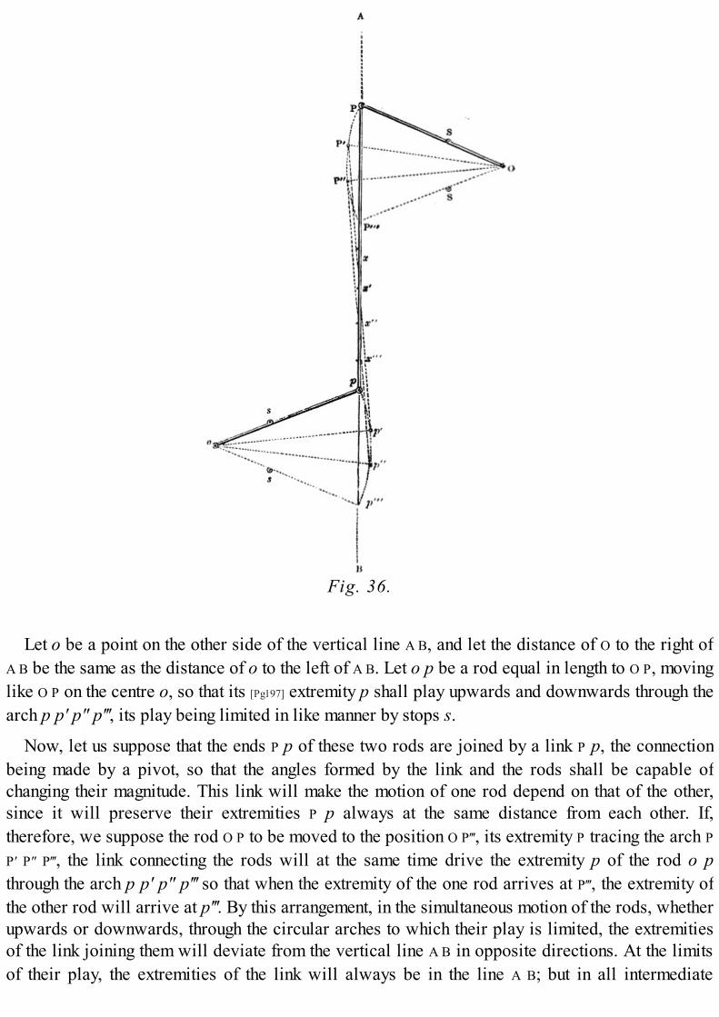
Fig. 36.
Let o be a point on the other side of the vertical line A B, and let the distance of O to the right ofA B be the same as the distance of o to the left of A B. Let o p be a rod equal in length to O P, movinglike O P on the centre o, so that its [Pg197] extremity p shall play upwards and downwards through thearch p p′ p″ p‴, its play being limited in like manner by stops s.
Now, let us suppose that the ends P p of these two rods are joined by a link P p, the connectionbeing made by a pivot, so that the angles formed by the link and the rods shall be capable ofchanging their magnitude. This link will make the motion of one rod depend on that of the other,since it will preserve their extremities P p always at the same distance from each other. If,therefore, we suppose the rod O P to be moved to the position O P‴, its extremity P tracing the arch PP′ P″ P‴, the link connecting the rods will at the same time drive the extremity p of the rod o pthrough the arch p p′ p″ p‴ so that when the extremity of the one rod arrives at P‴, the extremity ofthe other rod will arrive at p‴. By this arrangement, in the simultaneous motion of the rods, whetherupwards or downwards, through the circular arches to which their play is limited, the extremitiesof the link joining them will deviate from the vertical line A B in opposite directions. At the limitsof their play, the extremities of the link will always be in the line A B; but in all intermediate

positions, the lower extremity of the link will be to the right of A B, and its upper extremity to theleft of A B. So far as the derangement of the lower extremity of the link is concerned, the mattercomposing the link would be transferred to the right of A B, and so far as the upper extremity of thelink is concerned, the matter composing it would be transferred to the left of A B.
By the combined effects of these contrary derangements of the extremities of the link from thevertical line, it might be expected that a point would exist, in the middle of the link, where the twocontrary derangements would neutralise each other, and which point would therefore be expectedto be disturbed neither to the right nor to the left, but to be moved upwards and downwards in thevertical line A B. Such is the principle of the parallel motion; and in fact the middle point of thelink will move for all practical purposes accurately in the vertical line A B, provided that theangular play of the levers O P and o p does not exceed a certain [Pg198] limit, within which, inpractice, their motion may always be restrained.
To trace the motion of the middle point of the link more minutely, let P P′ P″ P‴ be four positionsof the lever O P, and let p p′ p″ p‴ be the four corresponding positions of the lever o p. In thepositions O P o p, the link will take the position P p, in which the entire link will be vertical, andits middle point x will therefore be in the vertical line A B.
When the one rod takes the position O P′, the other rod will have the position o p′; and the linkwill have the position P′ p′. The middle point of the link will be at x′, which will be found to be onthe vertical line A B. Thus one half of the link P′ x′ will be to the left of the vertical line A B; whilethe other half, p′ x′, will be to the right of the vertical line; the derangement from the vertical lineaffecting each half of the link in contrary directions.
Again, taking the one rod in the position O P″, the corresponding position of the other rod will beo p″, and the position of the link will be P″ p″. If the middle point of the link in this position betaken, it will be found to be at x″, on the vertical line A B; and, as before, one half of the link P″ x″will be thrown to the left of the vertical line, while the other half p″ x″, will be thrown to the rightof the vertical line.
Finally, let the one rod be in its lowest position, O P‴, while the other rod shall take thecorresponding position, o p‴. The direction of the link P‴ p‴ will now coincide with the verticalline; and its middle point x‴ will therefore be upon that line. The previous derangement of theextremities of the rod, to the right and to the left, are now redressed, and all the parts of the rodhave assumed the vertical position.
It is plain, therefore, that by such means the alternate motion of a point such as P or p, upwardsand downwards in a circular arch, may be made to produce the alternate motions of another pointx, upwards and downwards in a straight line.
(120.) Although the guidance of the air-pump rod in a true vertical line is not so necessary asthat of the steam piston, [Pg199] and as the air-pump piston is always brought down by its own weightand that of its rod, the connection of the air-pump piston-rod with the beam, by any contrivance ofthe kind now described, was not so necessary. Nevertheless, by a slight addition to the mechanicalcontrivance which has been just described, Watt obtained the means of at once preserving the truerectilinear motion of both piston-rods.

Fig. 37.
Let the lever represented by O P in fig. 36. be conceived to be prolonged to twice its length, asrepresented in fig. 37., so that O P′ shall be twice O P. Let the points P p be connected by a link asbefore. Let a link P′ x′, equal in length to the link P p be attached to the point P′, and let the extremityx′ of this link be connected with the point p by another link, equal in length to P P′, by pivots at x′and p, so that the figure P P′ x′ p shall be a jointed parallelogram, the angles of which will becapable of altering their magnitude with every change of position of the rods o p and O P. Thus,when the rod O P descends, the angles of the parallelogram at P and x′ will be diminished inmagnitude, while the angles at P′ and p will be increased in magnitude. Now, let a line beconceived to be drawn from O to x′. It is evident that that line will pass through the middle point ofthe link p P, for the triangle O P x is in all respects similar to the greater triangle O P′ x′ only on halfthe scale, so that every side of the one is [Pg200] half the corresponding side of the other. Therefore Px is half the length of P′ x′; but P′ x′ was made equal to P p, and therefore p x is half of P p, that is tosay, x is the middle point of P p.
It has been already shown, that in the alternate motion of the rods o p, O P in ascending anddescending, the point x is moved upwards and downwards in a true vertical line. Now since thetriangle O P x is in all respects similar to O P′ x′, and subject to a similar motion during the ascentand descent of the rods, it is apparent that the point x′ must be subject to a motion in all respectssimilar to that which affects the points x, except that the point x′ will move through double thespace. In fact, the principle of the mechanism is precisely similar to that of the commonpantograph, where two rods are so connected as that the motion of the one governs the motion ofthe other, so that whatever line or figure may be described by one, a similar line or figure must bedescribed by the other. Since, then, the point x is moved upwards and downwards in a verticalstraight line, the point x′ will also be moved in a vertical straight line of double the length.
If such an arrangement of mechanism as has been here described can be connected with thebeam of the steam engine, so that while the point x′ is attached to the top of the steam piston, andthe space through which it ascends and descends shall be equal to the length of the stroke of thatpiston, the point x shall be attached to the rod of the air-pump piston, the stroke of the latter beinghalf that of the steam piston, then the points x′ and x will guide the motion of the two pistons so asto preserve them in true vertical straight lines.

The manner in which these ideas are reduced to practice admits of easy explanation: let thepoint O be the centre of the great working beam, and let O P′ be the arm of the beam on the side ofthe steam cylinder. Let P be a pivot upon the beam, at the middle point between its centre O and itsextremity P′; and let the links P p, P′ x′, and P p be jointed together, as already described. Let thepoint or pivot o be attached to some part of the fixed framing of the engine or engine house, and letthe rod o p, equal to half the arm of the beam, be attached by a pivot to the corner of theparallelogram at [Pg201] p. Let the end of the steam piston-rod be attached to the corner of theparallelogram x′, and let the end of the air-pump be attached to the middle point x of the link P p;by which arrangement it is evident that the rectilinear motion of the two piston-rods will berendered compatible with the alternate circular motions of the points P′ and P on the beam.
Among the many mechanical inventions produced by the fertile genius of Watt, there is nonewhich has excited such universal, such unqualified, and such merited admiration as that of theparallel motion. It is indeed impossible, even for an eye unaccustomed to view mechanicalcombinations, to behold the beam of a steam engine moving the pistons, through the instrumentalityof the parallel motion, without an instinctive feeling of pleasure at the unexpected fulfilment of anend by means having so little apparent connection with it. When this feeling was expressed to Watthimself, by those who first beheld the performance of this exquisite mechanism, he exclaimed withhis usual vivacity, that he himself, when he first beheld his own contrivance in action, was affectedby the same sense of pleasure and surprise at its regularity and precision. He said, that he receivedfrom it the same species of enjoyment that usually accompanies the first view of the successfulinvention of another person.
"Among the parts composing the steam engine, you have doubtless," says M. Arago, "observed acertain articulated parallelogram. At each ascent and descent of the piston, its angles open andclose with the sweetness—I had almost said with the grace—which charms you in the gestures of aconsummate actor. Follow with your eye alternately the progress of its successive changes, andyou will find them subject to the most curious geometrical conditions. You will see, that of the fourangles of the jointed parallelogram, three describe circular arches, but the fourth which holds thepiston-rod is moved nearly in a straight line. The immense utility of this result strikesmechanicians with even less force than the simplicity of the means by which Watt has attained it."
The parallel motion, of which there are several other varieties, depending, however, generallyupon the same [Pg202] principle, formed part of a patent which Mr. Watt obtained in the year 1784,another part of which patent was for a locomotive engine, by which a carriage was to be propelledon a road. In a letter to Mr. Smeaton dated 22d October, in the same year, Watt says,—
"I have lately contrived several methods of getting entirely rid of all the chains and circulararches about the great levers of steam engines, and nevertheless making the piston-rods ascend anddescend perpendicularly, without any sliding motions or right-lined guides, merely bycombinations of motions about centres; and with this further advantage, that they answer equallywell to push upwards as to pull downwards, so that this method is applicable to our doubleengines which act both in the ascent and descent of their pistons.
"A rotative engine of this species with the new motion which is now at work in our manufactory(but must be sent away very soon) answers admirably. It has cost much brain work to contriveproper working gear for these double engines, but I have at last done it tolerably well, by means ofthe circular valves, placed in an inverted position, so as to be opened by the force of the steam;

and they are kept shut by the working gear. We have erected an engine at Messrs. Goodwyne andCo.'s brewery, East Smithfield, London."
Fig. 38.
(121.) By the contrivance which has been explained above, the force of the piston in ascendingand descending would be conveyed to the working end of the beam; and the next problem whichWatt had to solve was, to produce by the force exerted by the working end of the beam inascending and descending a continuous motion of rotation. In the first instance he proposed toaccomplish this by a crank placed upon the axle to which rotation was to be imparted, and drivenby a rod connecting it with the working end of the beam. Let K (fig. 38.) be the centre, to whichmotion is to be imparted by the working end H of the beam. On the axle K suppose a short lever K I
to be fixed so that when K I is turned round the centre K, the axle must turn with it. Let an iron rod,the weight of which shall balance the piston and piston-rod at the other end of the beam, beconnected by joints with the working end H of the beam, and the extremity I of the [Pg203] lever K I.As the end H of the beam is moved upwards and downwards, the lever K I will be turned round thecentre K, taking successively the positions represented by faint lines in the figure; and thus amotion of continued rotation will be imparted to the axle K.
This simple and effectual expedient of producing a continued rotatory motion by a crank wasabandoned by Watt, as already explained, by reason of a patent having been obtained uponinformation of his experiments surreptitiously procured. To avoid litigation, he therefore
substituted for the crank the sun and planet wheel already described; but at the expiration of thepatent, which restricted the use of the crank, the sun and planet wheel was discontinued in Watt'sengine, and the crank restored.
(122.) Whether the crank or the sun and planet wheel be used, there is still a difficulty in themaintenance of a regular motion of rotation. In the various positions which the crank andconnecting rod assume throughout a complete revolution, there are two in which the moving powerloses all influence in impelling the crank. These positions are those which the crank assumes whenthe piston is at the top and bottom of the [Pg204] cylinder, and is just about to change the direction ofits motion. When the piston is at the bottom of the cylinder, the pivot I (fig. 38.), by which theconnecting rod H I is attached to the end of the crank, is immediately over the axle K of the crank,and under the pivot H, which joins the upper end of the connecting rod with the beam. In fact, inthis position the connecting rod and crank are in the same straight line, extending from the end ofthe beam to the axle of the crank. The steam, on entering the cylinder below the piston, andpressing it upwards, would produce a corresponding downward force on the connecting rod at H,which would be continued along the connecting rod and crank to the axle K. It is evident that such aforce could have no tendency to turn the crank round, but would expend its whole energy inpressing the axle K downwards.
The other position in which the power loses its effect upon the crank is when the piston is at thetop of the cylinder. In this case, the working end of the beam will be at the lowest point of its play,and the crank-pin I will be immediately below the axle K; so that K will be placed immediatelybetween H and I. When the steam presses on the top of the piston, it will expend its force indrawing the end H of the connecting rod upwards, by which the crank-pin I will likewise be drawnupwards. It is evident that this force can have no effect in turning the crank round, but will expendits whole energy in producing an upward strain on the axle K.
If the crank were absolutely at rest in either of the positions above described, it is apparent thatthe engine could not be put in motion by the steam; but if the engine has been previously in motion,then the mass of matter forming the crank, and the axle on which the crank is formed, havingalready had a motion of rotation, will have a tendency to preserve the momentum it has received,and this tendency will be sufficient to throw the crank K I out of either of those critical positionswhich have been described. Having once escaped these dead points, then the connecting rodforming an angle, however obtuse or acute, with the crank, the pressure or pull upon the formerwill have a tendency to produce rotation in the latter. As the crank revolves, however, theinfluence [Pg205] of the connecting rod upon it will vary according to the angle formed by theconnecting rod and crank. When that angle is a right angle, then the effect of the connecting rod onthe crank is greatest, since the force upon it has the advantage of the whole leverage of the crank;but according as the angle formed by the crank and connecting rod becomes more or less acute orobtuse in the successive attitudes which they assume in the revolution of the crank, the influence ofthe connecting rod over the crank varies, changing from nothing at the two dead points alreadydescribed, to the full effect produced in the two positions where they are at right angles. Inconsequence of this varying leverage, by which the force with which the connecting rod is drivenby the steam is transmitted to the axle on which the crank revolves, a corresponding variation ofspeed would necessarily be produced in the motion imparted to the crank. The speed at the deadpoints would be least, being due altogether to the momentum already imparted to the revolving

mass of the crank and axle; and it would gradually increase and be greatest at the points where theeffect of the crank on the connecting rod is greatest. Although this change of speed would not affectthe actual mechanical efficacy of the machine, and although the same quantity of steam wouldperform the same work at the varying velocity as it would do if the velocity were regulated, yetthis variation of speed would be incompatible with the purposes to which it was now proposedthat the steam engine should be applied in manufactures. In these a regular uniform motion shouldbe imparted to the main axle.
(123.) One of the expedients which Watt proposed for the attainment of this end was, by placingtwo cranks on the same axle, in different positions, to be worked by different cylinders, so thatwhile one crank should be at its dead points, the other should be in the attitude most favourable forits action. This expedient has since, as we shall see, been carried into effect in steam vessels; butone more simple and efficient presented itself in the use of a fly-wheel.
On the main axle driven by the crank Watt placed a large wheel of metal, as represented in fig.43., called a fly-wheel. This wheel being well constructed, and nicely balanced on its [Pg206] axle,was subject to very little resistance from friction; any moving force which it would receive itwould therefore retain, and would be ready to impart such moving force to the main axle wheneverthat axle ceased to be driven by the power. When the crank, therefore, is in those positions inwhich the action of the power upon it is most efficient, a portion of the energy of the power isexpended in increasing the velocity of the mass of matter composing the fly-wheel. As the crankapproaches the dead points, the effect of the moving power upon the axle and upon the crank isgradually enfeebled, and at these points vanishes altogether. The momentum which has beenimparted to the fly-wheel then comes into play, and carries forward the axle and crank out of thedead points with a velocity very little less than that which it had when the crank was in the mostfavourable position for receiving the action of the moving power.
By this expedient, the motion of revolution received by the axle from the steam piston is subjectto no other variation than just the amount of change of momentum in the great mass of the fly-wheel,which is sufficient to extricate the crank twice in every revolution from the mechanical dilemma towhich its peculiar form exposes it; and this change of velocity may be reduced to as small anamount as can be requisite by giving the necessary weight and magnitude to the fly-wheel.

(124.) By such arrangements the motion imparted to the main axle K would be uniform, providedthat the moving power of the engine be always proportionate to the load which it drives. But in thegeneral application of the steam engine to manufactures it was evident that the amount of theresistance to which any given machine would be subject must be liable to variation. If, forexample, the engine drive a cotton-mill, it will have to impart motion to all the spinning frames inthat mill. The operation of one or more of these may from time to time be suspended, and themoving power would be relieved from a corresponding amount of resistance. If, under suchcircumstances, the energy of the moving power remained the same, the velocity with which themachines would be driven would be subject to variation, being increased whenever the operationof any portion of the machines usually [Pg207] driven by it is suspended; and, on the other hand,diminished when any increased number of machines are brought into operation. In fine, the speedwould vary nearly in the inverse proportion of the load driven, increasing as the load isdiminished, and vice versâ.
On the other hand, supposing that no change took place in the amount of the load driven by theengine, and that the same number of machines of whatever kind would have to be continuallydriven, the motion imparted to the main axle would still be subject to variation by the changesinevitable to the moving power. The piston of the engine being subject to an unvaried resistance, auniform motion could only be imparted to it, by maintaining a corresponding uniformity in theimpelling power. This would require a uniform supply of steam from the boiler, which wouldfurther imply a uniform rate of evaporation in the boiler, unless means were provided in theadmission of steam from the boiler to the cylinder to prevent any excess of steam which might beproduced in the boiler from reaching the cylinder.
Fig. 39.
Fig. 40.
This end was attained by a contrivance afterwards called the throttle-valve. An axis A B (figs.39, 40.) was placed across the steam pipe in a ring of cast-iron D E, of proper thickness. On thisaxis was fastened a thin circular plate T, of nearly the same diameter as the steam pipe. On theouter end B of this axle was placed a short lever or handle B C, by which it could be turned. Whenthe circular plate T was turned into such a position as to be at right angles to the length of the tube,it stopped the passage within the tube altogether, so that no steam could pass from the boiler to theengine. On the other hand, when the handle was turned through a fourth of a revolution from this
position, then the circular plate T had its plane in the direction of the length of the tube, so that itsedge would be presented towards the current of steam flowing from the boiler to the cylinder. Inthat position the passage within the tube [Pg208] would be necessarily unobstructed by the throttle-valve. In intermediate positions of the valve, as that represented in figs. 39, 40., the passage mightbe left more or less opened, so that steam from the boiler might be admitted to the cylinder in anyregulated quantity according to the position given to the lever B C.
A view of the throttle-valve taken by a section across the steam pipe is exhibited in fig. 40., anda section of it through the axis of the steam pipe is represented in fig. 39. The form of the valve issuch, that, if accurately constructed, the steam in passing from the boiler would have no effect byits pressure to alter any position which might be given to the valve; and any slight inaccuracy ofform which might give a tendency to the steam to alter the position would be easily counteractedby the friction of the valve upon its axle. The latter might be regulated at pleasure.
By this expedient, however the evaporation of water in the boiler might vary within practicallimits, the supply of steam to the cylinder would be rendered regular and uniform. If the boilerbecame too active, and produced more steam than was necessary to move the engine with its loadat the requisite speed, then the throttle-valve was shifted so as to contract the passage and limit thesupply of steam. If, on the other hand, the process of evaporation in the boiler was relaxed, then thethrottle-valve was placed with its edge more directed towards the steam. Independently of theboiler, if the load on the engine was lightened, then the same supply of steam to the cylinder wouldunduly accelerate the motion. In this case, likewise, the partial closing of the throttle-valve wouldlimit the supply of steam and regulate the motion; and if, on the other hand, the increase of loadupon the engine rendered necessary an increased supply of steam, then the opening of the throttle-valve would accomplish the purpose. By these means, therefore, a uniform motion might bemaintained, provided the vigilance of the engine-man was sufficient for the due management of thelever B C, and provided that the furnace under the boiler was kept in sufficient activity to supplythe greatest amount of steam which would be necessary [Pg209] for the maintenance of a uniformmotion with the throttle-valve fully opened.
(125.) Watt, however, soon perceived that the proper manipulation of the lever B C would beimpracticable with any degree of vigilance and skill which could be obtained from the personsemployed to attend the engine. He, therefore, adapted to this purpose a beautiful application of apiece of mechanism, which had been previously used in the regulation of mill-work, and which hassince been well known by the name of the Governor, and has always been deservedly a subject ofmuch admiration.
The governor is an apparatus by which the axle of the fly-wheel is made to regulate the throttle-valve, so that the moment that the axle begins to increase its velocity, it shifts the position of thethrottle-valve, so as to limit the supply of steam from the boiler, and thereby to check the increaseof speed. And on the other hand, whenever the velocity of the axle is diminished, the lever B C ismoved in the contrary direction, so as to open more fully the passage for the steam, and acceleratethe motion of the engine.
A small grooved wheel A B (fig. 41.) is attached to a vertical spindle supported in pivots orsockets C and D, in which it is capable of revolving. An endless cord works in the groove A B, andis carried over proper pulleys to the axle of the fly-wheel, where it likewise works in a groove.When this cord is properly tightened the motion of the fly-wheel will give motion to the wheel A B,

so that the velocity of the one will be subject to all the changes incidental to the velocity of theother. By this means the speed of the grooved wheel A B may be considered as representing thespeed of the fly-wheel, and of the machinery which the axle of the fly-wheel drives.
Fig. 41.
It is evident that the same end might be attained by substituting for the grooved wheel A B atoothed wheel, which might be connected by other toothed wheels, and proper shafts, and axleswith the axle of the fly-wheel.
A ring or collar E is placed on the upright spindle, so as to be capable of moving freely upwardsand downwards. To this ring are attached by pivots two short levers, E F, the [Pg210] pivots or jointsat E allowing these levers to play upon them. At F these levers are joined by pivots to other leversF G, which cross each other at H, where an axle or pin passes through them, and attaches them to theupright spindle C D. These intersecting levers are capable, however, of playing on this axle or pinH. To the ends G of these levers are attached two heavy balls of metal I. The levers F G pass throughslits in a metallic arch attached to the upright spindle, so as to be capable of revolving upon it. Ifthe balls I are drawn outwards from the vertical axis, it is evident that the ends F of the levers willbe drawn down, and therefore the pivots E likewise drawn down. In fact, the angles E F H willbecome more acute, and the angle F E F more obtuse. By these means the sliding ring E will bedrawn down. To this sliding ring E, and immediately above it, is attached a grooved collar, whichslides on the vertical spindle upwards and downwards with the ring E. In the grooved collar areinserted the prongs of a fork K, formed at the end of the lever K L, the fulcrum or pivot of the leverbeing at L. By this arrangement, when the divergence of the balls I causes the collar E to be drawndown, the fork K, whose prongs are inserted in the groove of that collar, is likewise drawn down;and, on the other hand, when, by reason of the balls I falling towards the [Pg211] vertical spindle, thecollar E is raised, the fork K is likewise raised.
The ascent and descent of the fork K necessarily produce a contrary motion in the other end N ofthe lever. This end is connected by a rod, or system of rods, with the end M of the short lever

which works the throttle-valve T. By such means the motion of the balls I, towards or from thevertical spindle, produces in the throttle-valve a corresponding motion; and they are so connectedthat the divergence of the balls I will cause the throttle-valve to close, while their descent towardsthe vertical spindle will cause it to open.
These arrangements being comprehended, let us suppose that, either by reason of a diminishedload upon the engine or an increased activity of the boiler, the speed has a tendency to increase.This would impart increased velocity to the grooved wheel A B, which would cause the balls I torevolve with an accelerated speed. The centrifugal force which attends their motion wouldtherefore give them a tendency to move from the axle, or to diverge. This would cause, by themeans already explained, the throttle-valve T to be partially closed, by which the supply of steamfrom the boiler to the cylinder would be diminished, and the energy of the moving power,therefore, mitigated. The undue increase of speed would thereby be prevented.
If, on the other hand, either by an increase of the load, or a diminished activity in the boiler, thespeed of the machine was lessened, a corresponding diminution of velocity would take place in thegrooved wheel A B. This would cause the balls I to revolve with less speed, and the centrifugalforce produced by their circular motion would be diminished. This force being thus no longer ablefully to counteract their gravity, they would fall towards the spindle, which would cause, asalready explained, the throttle-valve to be more fully opened. This would produce a more amplesupply of steam to the cylinder, by which the velocity of the machine would be restored to itsproper amount.
Fig. 42.
(126.) The principle which renders the governor so perfect a regulator of the velocity of themachine is difficult to be [Pg212] explained without having recourse to the aid of the technicallanguage of mathematical physics. As, however, this instrument is of such great practicalimportance, and has attracted such general admiration, it may be worth while here to attempt torender intelligible the mechanical principles which govern its operation. Let S (fig. 42.) be thepoint of suspension of a common pendulum S P, and let P O P′ be the arch of its vibration, so that theball P shall swing or vibrate alternately to the east and to the west of the lowest point O, throughthe arches O P′ and O P. It is a property of such an instrument that, provided the arch in which itvibrates be not considerable in magnitude, the time of its vibration will be the same whether the
arch be long or short. Thus, for example, if the pendulum, instead of vibrating in the arch P P′,vibrated in the arch p p′, the time which it would take to perform its vibrations would be the same.If, however, the magnitude of the arch of vibration be increased, then a variation will take place inthe time of vibration; but unless the arch of vibration be considerably increased, this variation willnot be great.
Now let it be supposed that while the pendulum P P′ continues to vibrate east and west throughthe arch P P′, it shall receive such an impulse from north and south as would, if it were not in a stateof previous vibration, cause it to vibrate between north and south, in an arch similar to the arch P P
′. This second vibration between north and south [Pg213] would not prevent the continuance of theother vibration between east and west; but the ball P would be at the same time affected by bothvibrations. While, in virtue of the vibration from east to west, the ball would swing from P to P′, itwould, in virtue of the other vibration, extend its motion towards the north to a distance from theline W E equal to half a vibration, and will return from that distance again to the position P′. Whilereturning from P′ to P, its second vibration will carry it towards the south to an equal distance onthe southern side of W E, and it will return again to the position P. If the combination of these twomotions or vibrations be attentively considered, it will be perceived that the effect on the ball willbe a circular motion, precisely similar to the circular motion of the balls of the governor alreadydescribed.
Now the time of vibration of the pendulum S P between east and west will not in any way beaffected by the second vibration, which it is supposed to receive between north and south, andtherefore the time the pendulum takes in moving from P to P′ and back again from P′ to P will be thesame whether it shall have simultaneously or not the other vibration between north and south.Hence it follows that the time of revolution of the circular pendulum will be equal to the time ofsimilar vibrations of the same pendulum, if, instead of having a circular motion, it were allowed tovibrate in the manner of a common pendulum.
If this point be understood, and if it also be remembered that the time of vibration of a commonpendulum is necessarily the same whether the arch of vibration be small or great, it will be easilyperceived that the revolving pendulum or governor will have nearly the same time of revolutionwhether it revolve in a large circle or a small one: in other words, whether the balls revolve at agreater or a less distance from the central spindle or axis. This, however, is to be understood onlyapproximately. When the angle of divergence of the balls is as considerable as it usually is ingovernors, the time of revolution at different distances from the axis will therefore be subject tosome variation, but to a very small one. [Pg214]
The centrifugal force (which is the name given in mechanics to that influence which makes abody revolving in a circle fly from the centre) depends conjointly on the velocity of revolution,and on the distance of the revolving body from the centre of the circle. If the velocity of revolutionbe the same, then the centrifugal force will increase in the same proportion as the distance of therevolving body from the centre. If, on the other hand, the distance of the revolving body from thecentre remain the same, the centrifugal force will increase in the same proportion as the square ofthe time of vibration diminishes, or, in other words, it will increase in the same proportion as thesquare of the number of revolutions per minute. It follows from this, therefore, that the greater isthe divergence of the balls of the governor, and the more rapidly they revolve, the greater will betheir centrifugal force. Now this centrifugal force, if it were not counterbalanced, would give the

balls a constant tendency to recede from the centre; but from the construction of the apparatus, thefurther they are removed from the centre the greater will be the effect of their gravitation inresisting the centrifugal force.
It is evident that the ball at P will have a greater tendency to fall by gravitation towards O than itwould have at p, because the acclivity of the arch descending towards O at P is greater than itsacclivity at p. The gravitation, therefore, or tendency of the ball to fall towards the central axisbeing greater at P than at p it will be able to resist a greater centrifugal force. This increasedcentrifugal force, which the ball would have revolving at the distance P above what it would haveat the distance p, is produced partly by the greater distance of the ball from the central axis, andpartly by the greater velocity of its motion. But it will be evident that the time of its revolution maynevertheless be the same, or nearly the same, at both distances. If it should appear that the actualvelocity of its motion of revolution at P be greater than its velocity at p, in the same proportion asthe circles in which they revolve, then it is evident that the time of revolution would be as muchincreased by the greater space which P will have to travel over, as it will have to be [Pg215]
diminished by the greater speed with which that space is traversed. The time of revolution,therefore, may be the same, or nearly the same, in both cases.
If this explanation be comprehended, it will not be difficult to apply it to the actual case of thegovernor. If a sudden increase of the energy of the moving power, or a diminution of the load,should give the machine an increased velocity, then the increased speed of the balls of thegovernor will give them an increased centrifugal force, which for the moment will be greater thanthe tendency of their gravitation to make them fall towards the vertical axis. This centrifugal force,therefore, prevailing, the balls will recede from the axis; but as they recede, their gravitationtowards the vertical axis will, as has been already explained, be increased, and will become equalto the centrifugal force produced by the increased velocity, provided that velocity do not exceed acertain limit. When the balls, by diverging, get such increased gravitation as to balance thecentrifugal force, then they will continue to revolve at a fixed distance from the vertical axis. Whenthis happens, the time of the revolution must be nearly the same as it was before their increaseddivergence; in other words, the proportion of the moving power to the load will be so restored bythe action of the levers of the governor on the throttle-valve that the machine will move at itsformer velocity, or nearly so.
The principle on which the governor acts, as just explained, necessarily supposes temporarydisarrangements of the speed. In fact, the governor, strictly speaking, does not maintain a uniformvelocity, but restores it after it has been disturbed. When a sudden change of motion of the enginetakes place, the governor being immediately affected will cause a corresponding alteration in thethrottle-valve; and this will not merely correct the change of motion, but it will, as it were, overdoit, and will cause a derangement of speed of the opposite kind. Thus if the speed be suddenlyincreased to an undue amount, then the governor being affected will first close the throttle-valvetoo much, so as to reduce the speed below the proper limit. This second error will again affect thegovernor in the contrary way, and the speed [Pg216] will again be increased rather too much. In thisway a succession of alterations of effect will ensue until the governor settles down into thatposition in which it will maintain the engine at the proper speed.
To prevent the inconvenience which would attend any excess of such variations, the governor ismade to act with great delicacy on the throttle-valve, so that even a considerable change in thedivergence of the balls shall not produce too much alteration in the opening of that valve: the steam

in the boiler should have at least 2 lbs. per square inch pressure more than is generally required inthe cylinder. This excess is necessary to afford scope for that extent of variation of the powerwhich it is the duty of the throttle-valve to regulate.
The governor is usually so adjusted as to make thirty-six revolutions per minute, when inuniform motion; but if the motion is increased to the rate of thirty-nine revolutions, the balls willfly to the utmost extent allowed them, being the limitation of the grooves in which their rods move;and if, on the other hand, the speed be diminished to thirty-four revolutions per minute, they willcollapse to the lowest extent of their play. The duty of the governor, therefore, is to correct smallercasual derangements of the velocity; but if any permanent change to a considerable extent be madeeither in the load driven by the machine or in the moving power supplied to it from the boiler, thena permanent change is necessary to be made in the connection between the governor and thethrottle-valve, so as to render the governor capable of regulating those smaller changes to whichthe speed of the machine is liable.
(127.) Having thus explained the principal mechanical contrivances provided by Watt for themaintenance and regulation of the rotatory motion to be produced by his double-acting steamengine, let us now consider the machine as a whole, and investigate the process of its operation. Asection of this engine is represented in fig. 43.
Fig. 43.
Steam is supplied from the boiler to the cylinder by the steam pipe S. The throttle-valve T in that

pipe, near the cylinder, is regulated by a system of levers connected with [Pg217] the governor. Thepiston P is accurately fitted in the steam cylinder C by packing, as already described in the single-acting engine. This piston, as it moves, divides the cylinder into two compartments, between whichthere is no communication by which steam or any other elastic fluid can pass. The upper steam boxB is divided into three compartments by the two valves. Above the upper steam valve V is acompartment communicating with the steam pipe; below the upper exhausting valve E is anothercompartment communicating with the eduction pipe which leads to the condenser. By the valves Vand E a communication may be opened or closed between the boiler on the one hand, or thecondenser on the other, and the top of the cylinder. The continuation S′ of the steam pipe leads tothe lower box B′, which, like the upper, is divided into three compartments by two valves V′ and E′.The upper compartment communicates with the steam pipe, and thereby with the boiler; and thelower compartment communicates with the eduction pipe, and thereby with the condenser. Bymeans of the two valves V′ and E′, a communication may be opened or closed between the steampipe on the one hand, or the exhausting pipe on the other, and the lower part of the cylinder. Thefour valves V, E, V′, and E′ are connected by a system of levers with a handle or spanner m, which,being driven downwards or upwards, is capable of opening or closing the valves in pairs, in themanner already described (116.). The condensers, the air-pump, and the hot-water pump, are in allrespects similar to those already described in the single-acting engine, except that the condensingjet is governed by a lever I, by which it is allowed to play continually in the condenser, and bywhich the quantity of water admitted through it is regulated. The cold-water pump N is worked bythe engine as already described in the single-acting engine, and supplies the cistern in which theair-pump and condenser are submerged, so as to keep down its temperature to the proper limit. Onthe air-pump rod R are two pins properly placed, so as to strike the spanner m, upwards anddownwards, at the proper times, when the piston approaches the termination of the stroke at the topor bottom of the cylinder. The pump L [Pg218] conducts the warm water drawn by the air-pump fromthe condenser to a proper reservoir for feeding the boiler. The vertical motion of the piston-rod ina straight line is rendered compatible with the circular motion of the end of the beam by theparallel motion already described. The point b, on the beam, moves upwards and downwards in acircular arch, of which the axis of the beam is the centre. In like manner the point d of the rod d cmoves upwards and downwards, in a similar arch of which the fixed pivot c is the centre. Thejoint or bar d b, which joins these two pivots, will be moved so that its middle point e will ascendand descend nearly in a straight line, as has been already explained (120.); [Pg219] opposite thispoint e is attached the piston-rod of the air-pump, which is accordingly guided upwards anddownwards by this means. The jointed parallelogram b d g f is attached to the beam by pivots;and, as has been explained (120.), the point g will be moved upwards and downwards in a straightline, through twice the space through which the point e is moved. To the point g the rod of thesteam piston is attached. Thus, the rods of the steam piston and air-pump are moved by the samesystem of jointed bars, and moved through spaces which are in the proportion of two to one.
Although this system of jointed rods forming the parallel motion, appears in the figure to consistonly of one parallelogram b d g f, and one rod c d, called the radius rod, it is, in fact, double, asimilar parallelogram and radius rod being attached to corresponding points, and in the samemanner on the other side of the beam; but from the view given in the cut, the one set of rods hidesthe other. The two systems of rods thus attached to opposite sides of the beam at several inchesasunder, are connected by cross rods, the ends of which form the pivots or joints, and extend

between the parallelograms. The ends of these rods are only visible in the figure. It is to themiddle of one of these rods, the end of which is represented at e, that the air-pump piston-rod isattached; and it is to the middle of another, the end of which is represented at g, that the steampiston-rod is attached. These two piston-rods, therefore, are driven, not immediately by either ofthe parallelograms forming the parallel motion, but by the bars extending between them.
To the working end of the beam H is attached a rod of cast-iron O, called the connecting rod, thelower end of which is attached to the crank by a pivot. The weight of the connecting rod is somade, that it shall balance the weight of the piston-rods of the air-pump and cylinder on the otherside of the beam; and the weight of the piston-rod of the cold-water pump N nearly balances theweight of the piston-rod of the hot-water pump L. Thus, so far as the weights of the machinery areconcerned, the engine is in equilibrium, and the piston would rest in any position indifferently inthe cylinder.
The axis of the fly-wheel on which the crank is formed is [Pg220] square in the middle part, wherethe fly-wheel is attached to it, but has cylindrical necks at each end, which rest in sockets orbearings supported by the framing of the machine, in which sockets the axis revolves freely. On theaxle of the crank is placed the fly-wheel, and connected with its axle is the governor Q, whichregulates the throttle-valve T in the manner already described.
Let us now suppose the engine to be in full operation. The piston being at the top of the cylinder,the spanner m will be raised by the lower pin on the air-pump rod, and the upper steam valve V,and the lower exhausting valve E′, will be opened, while the upper exhausting valve E and thelower steam valve V′ are closed. Steam will, therefore, be admitted above the piston, and thesteam which filled the cylinder below it will be drawn off to the condenser, where it will beconverted into water. The piston will, therefore, be urged by the pressure of the steam above it tothe bottom of the cylinder. As it approaches that limit, the spanner m will be struck downwards bythe upper pin on the air-pump rod, and the valves V and E′ will be closed, and at the same time thelower steam valve V′ and the upper exhausting valve E will be opened. Steam will, therefore, beadmitted below the piston, while the steam above it will be drawn off into the condenser, andconverted into water. The pressure of the steam, therefore, below the piston will urge it upwards,and in the same manner the motion will be continued.
While this process is going on in the cylinder and the condenser, the water formed in thecondenser will be gradually drawn off by the operation of the air-pump piston, in the same manneras explained in the single-acting engine; and at the same time the hot water thrown into the hot wellby the air-pump piston will be carried off by the hot-water pump L.
Such are the chief circumstances attending the continuance of the operation of the double-actingengine. It is only necessary here to recall what has been already explained respecting the operationof the fly-wheel. The commencement of the motion of the piston from the top and bottom of thecylinder is produced, not by the pressure of the steam upon it upwards or downwards, which must,for the reasons [Pg221] already explained, be entirely inefficient; but by the momentum of the fly-wheel, which extricates the crank from those positions in which the moving power cannot affect it.
The manner in which the motion of the crank affects the connecting rod at the dead pointsproduces an effect of great importance in the operation of the engine. When the crank-pin isapproaching the lowest point of its play, and therefore the piston approaching the top of the
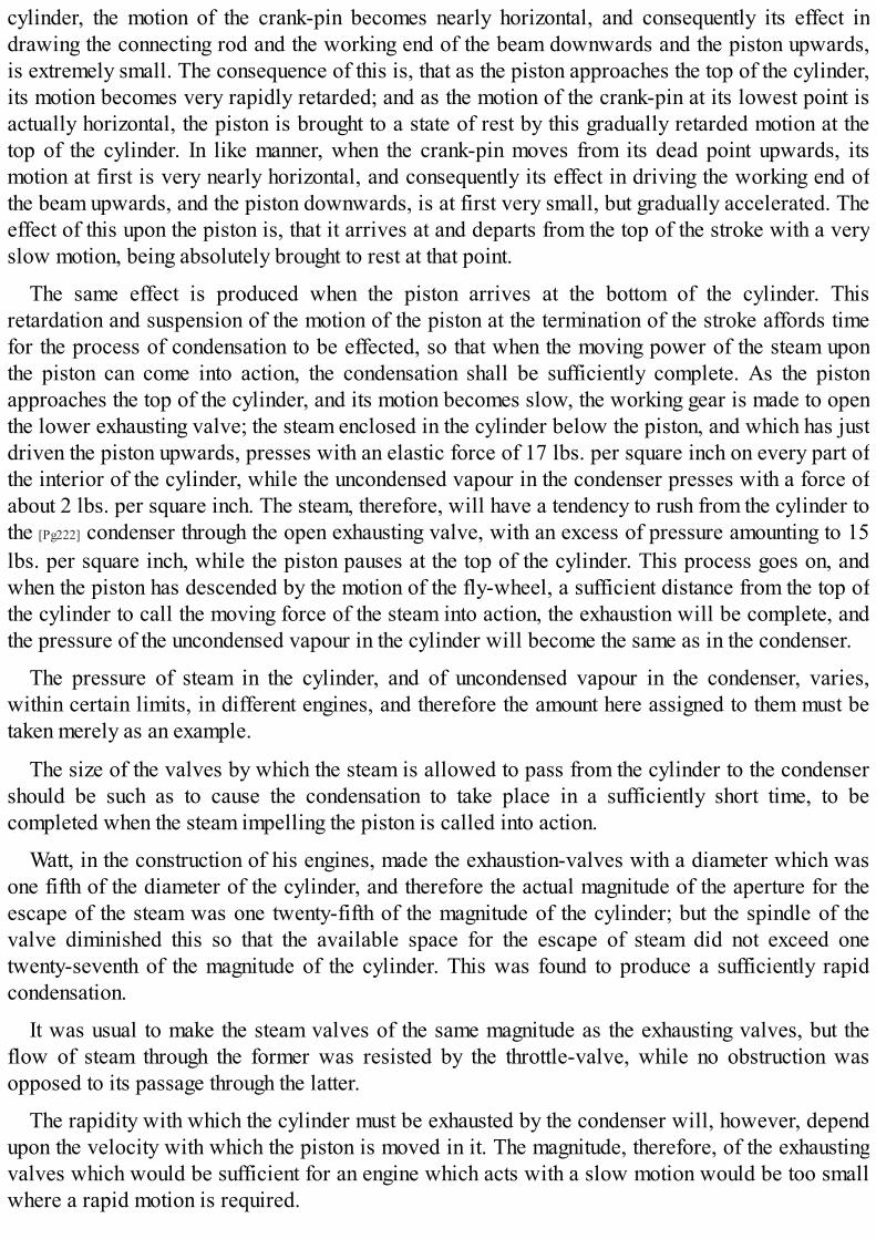
cylinder, the motion of the crank-pin becomes nearly horizontal, and consequently its effect indrawing the connecting rod and the working end of the beam downwards and the piston upwards,is extremely small. The consequence of this is, that as the piston approaches the top of the cylinder,its motion becomes very rapidly retarded; and as the motion of the crank-pin at its lowest point isactually horizontal, the piston is brought to a state of rest by this gradually retarded motion at thetop of the cylinder. In like manner, when the crank-pin moves from its dead point upwards, itsmotion at first is very nearly horizontal, and consequently its effect in driving the working end ofthe beam upwards, and the piston downwards, is at first very small, but gradually accelerated. Theeffect of this upon the piston is, that it arrives at and departs from the top of the stroke with a veryslow motion, being absolutely brought to rest at that point.
The same effect is produced when the piston arrives at the bottom of the cylinder. Thisretardation and suspension of the motion of the piston at the termination of the stroke affords timefor the process of condensation to be effected, so that when the moving power of the steam uponthe piston can come into action, the condensation shall be sufficiently complete. As the pistonapproaches the top of the cylinder, and its motion becomes slow, the working gear is made to openthe lower exhausting valve; the steam enclosed in the cylinder below the piston, and which has justdriven the piston upwards, presses with an elastic force of 17 lbs. per square inch on every part ofthe interior of the cylinder, while the uncondensed vapour in the condenser presses with a force ofabout 2 lbs. per square inch. The steam, therefore, will have a tendency to rush from the cylinder tothe [Pg222] condenser through the open exhausting valve, with an excess of pressure amounting to 15lbs. per square inch, while the piston pauses at the top of the cylinder. This process goes on, andwhen the piston has descended by the motion of the fly-wheel, a sufficient distance from the top ofthe cylinder to call the moving force of the steam into action, the exhaustion will be complete, andthe pressure of the uncondensed vapour in the cylinder will become the same as in the condenser.
The pressure of steam in the cylinder, and of uncondensed vapour in the condenser, varies,within certain limits, in different engines, and therefore the amount here assigned to them must betaken merely as an example.
The size of the valves by which the steam is allowed to pass from the cylinder to the condensershould be such as to cause the condensation to take place in a sufficiently short time, to becompleted when the steam impelling the piston is called into action.
Watt, in the construction of his engines, made the exhaustion-valves with a diameter which wasone fifth of the diameter of the cylinder, and therefore the actual magnitude of the aperture for theescape of the steam was one twenty-fifth of the magnitude of the cylinder; but the spindle of thevalve diminished this so that the available space for the escape of steam did not exceed onetwenty-seventh of the magnitude of the cylinder. This was found to produce a sufficiently rapidcondensation.
It was usual to make the steam valves of the same magnitude as the exhausting valves, but theflow of steam through the former was resisted by the throttle-valve, while no obstruction wasopposed to its passage through the latter.
The rapidity with which the cylinder must be exhausted by the condenser will, however, dependupon the velocity with which the piston is moved in it. The magnitude, therefore, of the exhaustingvalves which would be sufficient for an engine which acts with a slow motion would be too smallwhere a rapid motion is required.
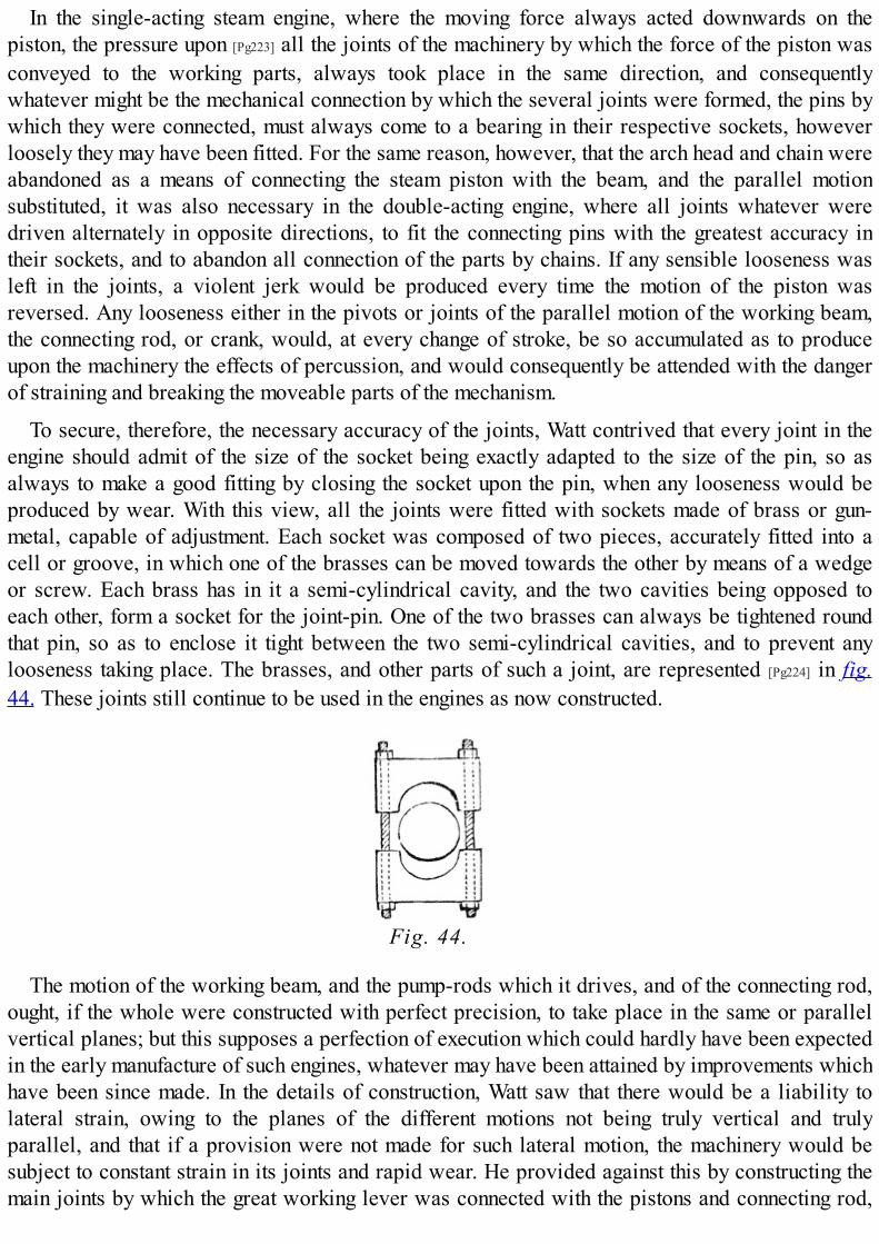
In the single-acting steam engine, where the moving force always acted downwards on thepiston, the pressure upon [Pg223] all the joints of the machinery by which the force of the piston wasconveyed to the working parts, always took place in the same direction, and consequentlywhatever might be the mechanical connection by which the several joints were formed, the pins bywhich they were connected, must always come to a bearing in their respective sockets, howeverloosely they may have been fitted. For the same reason, however, that the arch head and chain wereabandoned as a means of connecting the steam piston with the beam, and the parallel motionsubstituted, it was also necessary in the double-acting engine, where all joints whatever weredriven alternately in opposite directions, to fit the connecting pins with the greatest accuracy intheir sockets, and to abandon all connection of the parts by chains. If any sensible looseness wasleft in the joints, a violent jerk would be produced every time the motion of the piston wasreversed. Any looseness either in the pivots or joints of the parallel motion of the working beam,the connecting rod, or crank, would, at every change of stroke, be so accumulated as to produceupon the machinery the effects of percussion, and would consequently be attended with the dangerof straining and breaking the moveable parts of the mechanism.
To secure, therefore, the necessary accuracy of the joints, Watt contrived that every joint in theengine should admit of the size of the socket being exactly adapted to the size of the pin, so asalways to make a good fitting by closing the socket upon the pin, when any looseness would beproduced by wear. With this view, all the joints were fitted with sockets made of brass or gun-metal, capable of adjustment. Each socket was composed of two pieces, accurately fitted into acell or groove, in which one of the brasses can be moved towards the other by means of a wedgeor screw. Each brass has in it a semi-cylindrical cavity, and the two cavities being opposed toeach other, form a socket for the joint-pin. One of the two brasses can always be tightened roundthat pin, so as to enclose it tight between the two semi-cylindrical cavities, and to prevent anylooseness taking place. The brasses, and other parts of such a joint, are represented [Pg224] in fig.44. These joints still continue to be used in the engines as now constructed.
Fig. 44.
The motion of the working beam, and the pump-rods which it drives, and of the connecting rod,ought, if the whole were constructed with perfect precision, to take place in the same or parallelvertical planes; but this supposes a perfection of execution which could hardly have been expectedin the early manufacture of such engines, whatever may have been attained by improvements whichhave been since made. In the details of construction, Watt saw that there would be a liability tolateral strain, owing to the planes of the different motions not being truly vertical and trulyparallel, and that if a provision were not made for such lateral motion, the machinery would besubject to constant strain in its joints and rapid wear. He provided against this by constructing themain joints by which the great working lever was connected with the pistons and connecting rod,
so as to form universal joints, giving freedom of motion laterally as well as vertically.
The great lever, or working beam, was so called from being originally made from a beam ofoak. It is now, however, universally constructed of cast-iron. The connecting rod is also made ofcast-iron, and attached to the beam and to the crank by axles or pivots.
The mechanism by which the four valves are opened and closed, is subject to considerablevariation in different engines. They have been described above as being opened and closedsimultaneously by a single lever. Sometimes, however, they are opened alternately in pairs by twodistinct levers driven by two pins attached to the air-pump rod. One pin strikes the lever, whichopens and closes the upper steam valve, and lower exhausting valve; the other strikes that whichopens and closes the lower steam valve and upper exhausting valve.
Since the date of the earlier double-acting engines, constructed by Boulton and Watt, a greatvariety of mechanical expedients have been practised for working the valves, by which the steamis admitted to and withdrawn from the [Pg225] cylinder. We shall here describe a few of thesemethods:—
(128.) The method of working the valves by pins on the air-pump rod driving levers connectedwith the valves has been, in almost all modern double-acting machines, superseded by anapparatus called an eccentric, by which the motion of the axle of the fly-wheel is made to openand close the valves at the proper times.
Fig. 45.
An eccentric is a metallic circle attached to a revolving axle, so that the centre of the circleshall not coincide with the centre round which the axle revolves. Let us suppose that G (fig. 45.), isa square revolving shaft. Let a circular plate of metal B D, having its centre at C, have a square holecut in it, corresponding to the shaft G, and let the shaft G pass through this square aperture, so thatthe circular plate B D shall be fastened upon the shaft, and capable of revolving with it as the shaftrevolves. The centre C of the circular plate B D will be carried round the centre G of the revolvingshaft, and will describe round it a circle, the radius of which will be the distance of the centre C ofthe circular plate from the centre of the shaft. Such circular plate so placed upon a shaft, andrevolving with it, is an eccentric.
Let E F be a metallic ring, formed of two semicircles of metal screwed together at H, so as to be
capable, by the adjustment of the screws, of having the circular aperture formed by the ringenlarged and diminished within certain [Pg226] small limits. Let this circular aperture be supposed tobe equal to the magnitude of the eccentric B D. To the circular ring E F let an arm L M be attached. Ifthe ring E F be placed around the eccentric B D, and that the screws H be so adjusted as to allow theeccentric B D to revolve within the ring E F, then while the eccentric revolves, the ring not partakingof its revolution, the arm L M will be alternately driven to the right and to the left, by the motion ofthe centre C of the eccentric as it revolves round the centre G of the axle. When the centre C of theeccentric is in the same horizontal line with the centre G, and to the left of it, then the position of LM will be that which is represented in fig. 45.; but when, after half a revolution of the main axle,the centre C of the eccentric is thrown on the other side of the centre G, then the point M will betransferred to the right, to a distance equal to twice the distance C G. Thus as the eccentric B D
revolves within the ring E F, that ring, together with the arm L M, will be alternately driven, rightand left, through a space equal to twice the distance between the centre of the eccentric and thecentre of the revolving shaft.
If we suppose a notch formed at the extremity of the arm L M, which is capable of embracing alever N M, moveable on a pivot at N, the motion of the eccentric would give to such a lever analternate motion from right to left, and vice versâ. If we suppose another lever N O connected withN M, and at right angles to it, forming what is called a bell-crank, then the alternate motion receivedby M, from right to left, would give a corresponding motion to the extremity O of the lever N O,upwards and downwards. If this last point O were attached to a vertical arm or shaft, it wouldimpart to such arm or shaft an alternate motion upwards and downwards, the extent of whichwould be regulated by the length of the levers respectively.
By such a contrivance the revolution of the fly-wheel shaft is made to give an alternate verticalmotion of any required extent to a vertical shaft placed near the cylinder, which may be soconnected with the valves as to open and close them. Since the upward and downward motion ofthis vertical shaft is governed by the alternate motion of the centre [Pg227] C to the right and to the leftof the centre G, it is evident that by the adjustment of the eccentric upon the fly-wheel shaft, thevalves may be opened and closed at any required position of the fly-wheel and crank, andtherefore at any required position of the piston in the cylinder.
Such is the contrivance by which the valves, whatever form may be given to them, are nowalmost universally worked in double-acting steam engines.
Having described the general structure and operation of the steam engine as improved by Watt,we shall now explain, in a more detailed manner, some parts of its machinery which have beenvariously constructed, and in which more or less improvements have been made.
OF THE COCKS AND VALVES.

(129.) In the steam engine, as well as in every other machine in which fluids act, it is necessaryto open or close, occasionally, the tubes or passages through which these fluids move. Theinstruments by which this is accomplished are called cocks or valves.
Cocks or valves may be classified by the manner in which they are opened: 1st, they may beopened by a motion similar to the lid of a box upon its hinges; 2d, they may be opened by beingraised directly upwards, in the same manner as the lid of a pot or kettle; 3d, they may be opened bya sliding motion, like that of the sash of a window or the lid of a box which slides in grooves; 4th,they may be opened by a motion of revolution, in the same manner as the cock of a beer-barrel isopened or closed. The term valve is more properly applied to the first and second of these classes;the third class are usually called slides, and the fourth cocks.
(130.) The single clack valve is the most simple example of the first class. It is usuallyconstructed by attaching to a plate of metal larger than the aperture which the valve is intended tostop, a piece of leather, and to the under side of this leather another piece of metal smaller than theaperture. The leather [Pg228] extending on one side beyond the larger metallic plate, and beingflexible, forms the hinge on which the valve plays. Such a valve is usually closed by its ownweight, and opened by the pressure of the fluid which passes through it. It is also held closed morefirmly by the pressure of the fluid whose return it is intended to obstruct. An example of this valveoccurs in the steam engine, in the passage between the condenser and the air-pump. The aperturewhich it stops is there a seat inclined at an angle whose inclination is such as to render the weightof the valve sufficient to close it. In cases where the valve is exposed to heat, as in the examplejust mentioned, where it is continually in contact with the hot water flowing from the condenser tothe air-pump, the use of leather is inadmissible, and in that case the metallic surface of the valve isground smooth to fit its seat.
The extent to which such a valve should be capable of opening, ought to be such that the apertureproduced by it shall be equal to the aperture which it stops. This will be effected if the anglethrough which it rises be about 30°.
Fig. 46.
The valve by which the air and water collected in the bottom of the air-pump are admitted topass through the air-pump piston is a double clack, consisting of two semicircular plates, havingthe hinges on the diameters of these semicircles, as represented in fig. 46.
(131.) Of the valves which are opened by a motion perpendicular to their seat, the most simpleis a flat metallic plate, made larger than the orifice which it is intended to stop, and ground so as torest in steam-tight contact with the surface surrounding the aperture. Such a valve is usually guidedin its perpendicular motion by a spindle passing through its centre, and sliding in holes made incross bars extending above and below the seat of the valve.
The conical steam-valves, which have been already described (116.), usually called spindle-valves, are the most common of this class. The best angle to be given to the conical seat is found inpractice to be 45°. With a less inclination the valve has a tendency to be fastened in its seat, and a

greater inclination would cause the top of the valve to occupy [Pg229] unnecessary space in thevalve-box. The area, or transverse section of the valve-box, should be rather more than double themagnitude of the upper surface of the valve, in order to allow a sufficiently free passage for thesteam, and the play of the valve should be such as to allow it to rise from its seat to a height notless than one fourth of the diameter of its upper surface.
The valves coming under this class are sometimes formed as spheres or hemispheres resting in aconical seat, and in such cases they are generally closed by their own weight, and opened by thepressure of the fluid which passes through them.
(132.) One of the advantages attending the use of slides, compared with the other form ofvalves, is the simplicity with which the same slide may be made to govern several passages, sothat a single motion with a slide may perform the office of two or more motions imparted toindependent valves.
In most modern engines the passage of the steam to and from the cylinder is governed by slidesof various forms, some of which we shall now explain.
Fig. 47.
(133.) In figs. 47. and 48. is represented a slide-valve contrived by Mr. Murray of Leeds. A B isa steam-tight case attached to the side of the cylinder; E F is a rod, which receives an alternatemotion, upwards and downwards, from the eccentric, or from whatever other part of the engine isintended to move the slide. This rod, passing through a stuffing-box, moves the slide G upwardsand downwards. S is the mouth of the steam pipe coming from the boiler; T is the mouth of a tube orpipe leading to the condenser; H is a passage leading to the top, and I to the bottom, of the cylinder.In the position of the slide represented in fig. 47., the steam coming from the boiler through S
passes through the space H to the top of the cylinder, while the steam from the bottom of thecylinder passes through the space I into the tube T, and goes to the condenser. When the rod [Pg230] E
F is raised to the position represented in fig. 48., then the passage H is thrown into communicationwith the tube T, while the passage I is made to communicate with the tube S. Steam, therefore,passes from the boiler through I below the piston, while the steam which was above the piston,passing through H into T, goes to the condenser. Thus the single slide G performs the office of the
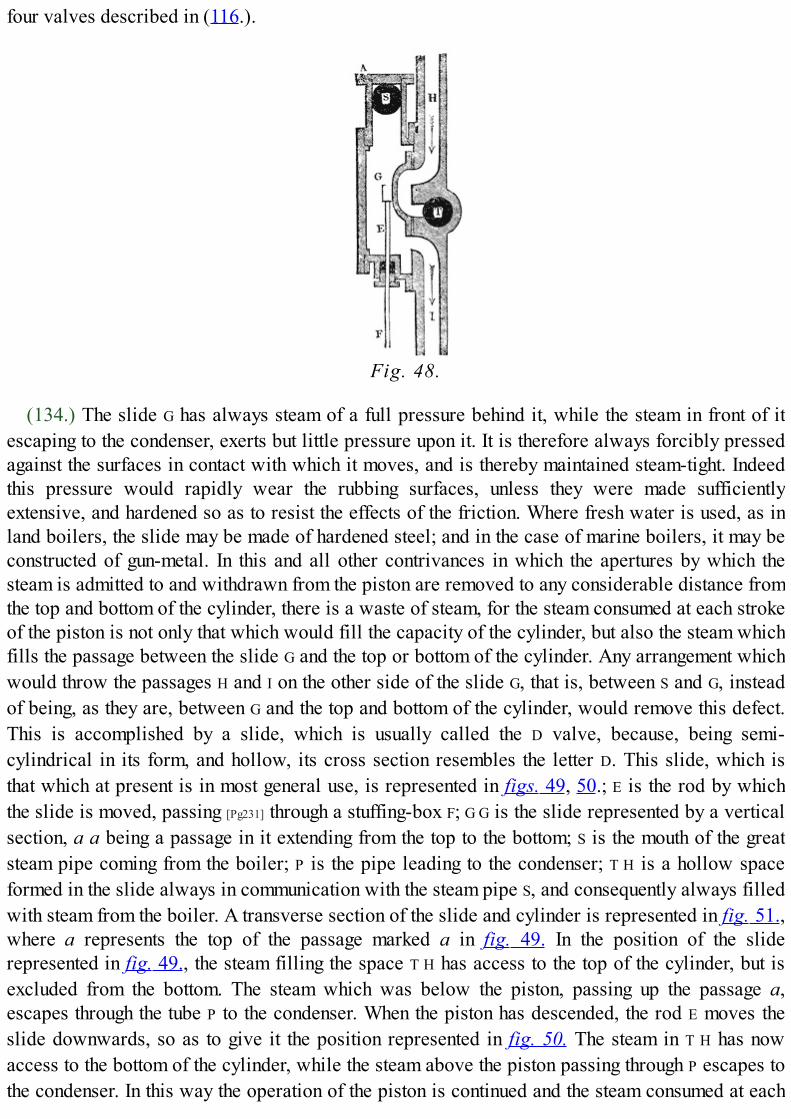
four valves described in (116.).
Fig. 48.
(134.) The slide G has always steam of a full pressure behind it, while the steam in front of itescaping to the condenser, exerts but little pressure upon it. It is therefore always forcibly pressedagainst the surfaces in contact with which it moves, and is thereby maintained steam-tight. Indeedthis pressure would rapidly wear the rubbing surfaces, unless they were made sufficientlyextensive, and hardened so as to resist the effects of the friction. Where fresh water is used, as inland boilers, the slide may be made of hardened steel; and in the case of marine boilers, it may beconstructed of gun-metal. In this and all other contrivances in which the apertures by which thesteam is admitted to and withdrawn from the piston are removed to any considerable distance fromthe top and bottom of the cylinder, there is a waste of steam, for the steam consumed at each strokeof the piston is not only that which would fill the capacity of the cylinder, but also the steam whichfills the passage between the slide G and the top or bottom of the cylinder. Any arrangement whichwould throw the passages H and I on the other side of the slide G, that is, between S and G, insteadof being, as they are, between G and the top and bottom of the cylinder, would remove this defect.This is accomplished by a slide, which is usually called the D valve, because, being semi-cylindrical in its form, and hollow, its cross section resembles the letter D. This slide, which isthat which at present is in most general use, is represented in figs. 49, 50.; E is the rod by whichthe slide is moved, passing [Pg231] through a stuffing-box F; G G is the slide represented by a verticalsection, a a being a passage in it extending from the top to the bottom; S is the mouth of the greatsteam pipe coming from the boiler; P is the pipe leading to the condenser; T H is a hollow spaceformed in the slide always in communication with the steam pipe S, and consequently always filledwith steam from the boiler. A transverse section of the slide and cylinder is represented in fig. 51.,where a represents the top of the passage marked a in fig. 49. In the position of the sliderepresented in fig. 49., the steam filling the space T H has access to the top of the cylinder, but isexcluded from the bottom. The steam which was below the piston, passing up the passage a,escapes through the tube P to the condenser. When the piston has descended, the rod E moves theslide downwards, so as to give it the position represented in fig. 50. The steam in T H has nowaccess to the bottom of the cylinder, while the steam above the piston passing through P escapes tothe condenser. In this way the operation of the piston is continued and the steam consumed at each

stroke only exceeds the capacity of the cylinder by what is necessary to fill the passages betweenthe slide and the cylinder.
Figs. 49., 50.
Fig. 51.
In a slide constructed in this manner, the steam filling the space T H has a tendency to press theslide back, so as to break the contact of the rubbing surfaces, and thereby to cause the steam to leakfrom the space T H to the back of the slide. This is counteracted by the packing x, at the back of theslide.
In engines of very long stroke, the extent of the rubbing surfaces of slides of this kind renders itdifficult to keep [Pg232] them in steam-tight contact and to insure their uniform wear. In such cases,therefore, separate slides, upon the same principle, are provided at the top and bottom of thecylinder, moved, however, by a single rod of communication.
(135.) In slides, as we have here described them, the same motion which admits steam to eitherend of the cylinder, withdraws it from the other end. Such an arrangement is only compatible withthe operation of a cylinder which works without expansion; for in such a cylinder the full flow ofsteam to the piston is only interrupted for a moment during the change of position of the slide. Butif the steam act expansively, it would be necessary to move the slide, so as to stop its flow to oneend of the cylinder, without at the same time obstructing the escape of steam from the other end tothe condenser. It would therefore be necessary that the slide should close the passage leading to thecylinder at one end, without at the same time obstructing the communication between the passagefrom the cylinder to the condenser at the other end. On the arrival of the piston, however, at thebottom of the cylinder, it would be necessary immediately to put the lower passage to the cylinderin communication with the steam pipe, and the upper passage in communication with thecondenser. This would necessarily suppose two motions of the slide as well as somemodifications in its length. Let the length of the slide be such that when the passage to the top of thecylinder is stopped, the lower part of the slide shall not reach the passage to the lower part of thecylinder; and let such a provision be made in the mechanism by which the rod E governing the slide

is driven that it shall receive two motions during the descent of the piston, the first to be impartedto it at the moment the steam is to be cut off, and the second just before the termination of thestroke. Let the position of the slide, at the commencement of the stroke, be represented in fig. 52.,and let it be required that the steam shall be cut off at one half of the stroke. When the piston hasmade half the stroke, the rod governing the slide is moved downwards, so as to throw the slideinto the position represented in fig. 53. The passage between the steam pipe and the cylinder is[Pg233] now stopped at both ends; but the passage from the bottom of the cylinder to the condenserremains open. During the remainder of the stroke, therefore, the steam in the cylinder worksexpansively. As the piston approaches the bottom of the cylinder, another motion is imparted to therod governing the slide, by which the latter is thrown into the position represented in fig. 54.Steam now flows below the piston while the steam above it passes to the condenser. In a similarmanner, by two motions successively imparted to the slide during the ascent of the piston, thesteam may be cut off at half stroke; and it is evident that by regulating the time at which thesemotions are given to the slide, the steam may be worked expansively, to any required extent.
Figs. 52., 53., 54.
It is easy to conceive various mechanical means by which, in the same engine, the point at whichthe steam is cut off may be regulated at pleasure.
In cases where the motion of the piston is very rapid, as in locomotive engines, it is desirablethat the passages to and from the cylinder should be opened very suddenly. This is difficult to beaccomplished with any form of slide consisting of a single aperture; but if, instead of admitting thesteam to the cylinder by a single aperture, the same magnitude of opening were divided amongseveral apertures, then a proportionally less extent of motion in the slide would clear the passagefor the steam, and consequently greater suddenness of opening would be effected. [Pg234]
The great advantages in the economy of fuel resulting from the application of the expansiveprinciple have, of late years forced themselves on the attention of engineers, and considerableimprovements have been made in its application, especially in the case of marine engines used forlong voyages, in which the economy of fuel has become an object of the last importance. Themechanism by which expansive slides are moved, is made capable of adjustment, so that the partof the stroke at which the steam is cut off, can be altered at pleasure. The working power of theengine, therefore, instead of being controlled by the throttle-valve, is regulated by the greater or
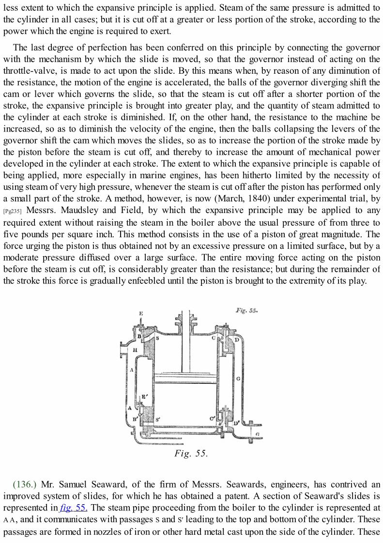
less extent to which the expansive principle is applied. Steam of the same pressure is admitted tothe cylinder in all cases; but it is cut off at a greater or less portion of the stroke, according to thepower which the engine is required to exert.
The last degree of perfection has been conferred on this principle by connecting the governorwith the mechanism by which the slide is moved, so that the governor instead of acting on thethrottle-valve, is made to act upon the slide. By this means when, by reason of any diminution ofthe resistance, the motion of the engine is accelerated, the balls of the governor diverging shift thecam or lever which governs the slide, so that the steam is cut off after a shorter portion of thestroke, the expansive principle is brought into greater play, and the quantity of steam admitted tothe cylinder at each stroke is diminished. If, on the other hand, the resistance to the machine beincreased, so as to diminish the velocity of the engine, then the balls collapsing the levers of thegovernor shift the cam which moves the slides, so as to increase the portion of the stroke made bythe piston before the steam is cut off, and thereby to increase the amount of mechanical powerdeveloped in the cylinder at each stroke. The extent to which the expansive principle is capable ofbeing applied, more especially in marine engines, has been hitherto limited by the necessity ofusing steam of very high pressure, whenever the steam is cut off after the piston has performed onlya small part of the stroke. A method, however, is now (March, 1840) under experimental trial, by[Pg235] Messrs. Maudsley and Field, by which the expansive principle may be applied to anyrequired extent without raising the steam in the boiler above the usual pressure of from three tofive pounds per square inch. This method consists in the use of a piston of great magnitude. Theforce urging the piston is thus obtained not by an excessive pressure on a limited surface, but by amoderate pressure diffused over a large surface. The entire moving force acting on the pistonbefore the steam is cut off, is considerably greater than the resistance; but during the remainder ofthe stroke this force is gradually enfeebled until the piston is brought to the extremity of its play.
Fig. 55.
(136.) Mr. Samuel Seaward, of the firm of Messrs. Seawards, engineers, has contrived animproved system of slides, for which he has obtained a patent. A section of Seaward's slides isrepresented in fig. 55. The steam pipe proceeding from the boiler to the cylinder is represented atA A, and it communicates with passages S and S′ leading to the top and bottom of the cylinder. Thesepassages are formed in nozzles of iron or other hard metal cast upon the side of the cylinder. These

nozzles present a smooth face outwards, upon which the slides B B′, also formed with smooth faces,play. The slides B B′ are attached by knuckle-joints to rods E E′, which move through stuffing-boxes,and the [Pg236] connection of these rods with the slides is such that the slides have play so as todetach their surfaces easily from the smooth surfaces of the nozzles when not pressed against thesesurfaces. The steam in the steam pipe A A will press against the backs of the slides B B′, and keeptheir faces in steam-tight contact with the smooth surfaces of the nozzles. These slides may beopened or closed by proper mechanism at any point of the stroke. When steam is to be admitted tothe top of the cylinder, the upper slide is raised and the passage S opened; and when it is to beadmitted to the bottom of the cylinder, the lower slide is raised and the passage S′ opened; and itscommunication to the top or bottom of the cylinder is stopped by the lowering of these slidesrespectively. On the other side of the cylinder are provided two passages C C′ leading to a pipe G,which is continued to the condenser. On this pipe are cast nozzles of iron or other metal presentingsmooth faces towards the cylinder, and having passages D D′ communicating between the top andbottom of the cylinder respectively and the pipe G G leading to the condenser. Two slides b b',having smooth faces turned from the cylinder, and pressing upon the faces of the nozzles D D′, aregoverned by rods playing through stuffing-boxes, in the same manner as already described. Thefaces of these slides being turned from the cylinder, the steam in the cylinder having freecommunication with them, has a tendency to keep them by its pressure in steam-tight contact withthe surfaces in which the apertures leading to the condenser are formed. These two slides may beopened or closed whenever it is necessary.
When the piston commences its descent, the upper steam slide is raised, so as to open thepassage S, and admit steam above the piston; and the lower exhausting slide b′ is also raised, so asto allow the steam below the piston to escape through G to the condenser, the other two passages S′
and C being closed by their respective slides. The slide which governs S is lowered at that part ofthe stroke at which the steam is intended to be cut off, the other slides remaining unchanged; andwhen the piston has reached the bottom of the cylinder, the lower steam slide opens the passage S′,and [Pg237] the upper exhausting slide opens the passage C; and at the same time the lower exhaustingslide closes the passage C′. Steam being admitted below the piston through S′, and at the same timethe steam above it being drawn away to the condenser through the open passage C and the tube G,the piston ascends. When it has reached that point at which the steam is intended to be cut off, theslide which governs S′ is lowered, the other slides remaining unaltered, and the upward stroke iscompleted in the same manner as the downward.
These four slides may be governed by a single lever, or they may be moved by separate means.From the small spaces between the several slides and the body of the cylinder, it will be evidentthat the waste of steam by this contrivance will be very small.
In the slide valves commonly used, the packing of hemp at the back of the slide, by which thepressure necessary to keep the slide in steam-tight contact is obtained, requires constant attentionfrom the engine-man while the engine is at work. Any neglect of this will produce a correspondingloss in the power of the engine; and accordingly it is found that in many cases where engines workinefficiently, the defect is owing either to ignorance or want of attention on the part of the engine-man in the packing of the slides. In Seaward's slides no hemp packing is used, nor is any attentionon the part of the engine-man required after the slides are first adjusted. The slides receive thepressure necessary to keep them in steam-tight contact with the surfaces of the nozzles from the

steam itself, which acts behind them.
The eduction and steam slides being independent of each other, they may be adjusted so that theengine shall work expansively in any required degree; and this may be accomplished either byworking the slides by separate mechanism, or by a single eccentric.
One of the advantages claimed by the patentees for these slides is, that the engines are securedfrom the accidents which arise from the accumulation of water within the steam cylinder. If such acircumstance should occur, the action of the piston will press the water against the faces of thesteam [Pg238] slides, and the play allowed to them by their connection with the rods which movethem permits their faces to be raised from the surfaces of the nozzles, so that the water collected inthe cylinder shall be driven into the steam pipe, and sent back from thence to the boiler.
Fig. 56.
(137.) Of the cocks or valves which are opened and closed by the motion of an axis passingthrough their centre, the throttle-valve, whether worked by hand or by the governor, is an example.But the most common form for cocks is that of a cylindrical or slightly conical plug (fig. 56.),inserted in an aperture of corresponding magnitude passing across the pipe or passage which thecock is intended to open or close. One or more holes are pierced transversely in the cock, andwhen the cock is turned so that these holes run in the direction of the tube, the passage through thetube is opened; but when the passage through the cock is placed at right angles to the tube, then thesides of the tube stop the ends of the passage in the cock, and the passage through the tube isobstructed. The simple cock is designed to open or close the passage through a single tube. Whenthe cock is turned, as in fig. 57., so that the passage through the cock shall be at right angles to thelength of the tube, then the passage through the tube is stopped; but when the cock is turned fromthat position through a quarter of a revolution, as in fig. 58., then the passage through the cock takesthe direction of the passage through the tube, and the cock is opened, and the passage through thetube unobstructed. In such a cock the passage may be more or less throttled by [Pg239] adjusting theposition of the cock, so that a part of the opening in it shall be covered by the side of the tube.
Figs. 57., 58.
(138.) It is sometimes required to put one tube or passage alternately in communication with twoothers. This is accomplished by a two-way cock. In this cock the passage is curved, opening

usually at points on the surface of the cock, at right angles to each other. Such a cock has alreadybeen described, and its use illustrated in the description of the Marquis of Worcester's engine(17.); the two-way cock, as represented at K and R (fig. 4.), being the means by which steam andwater are alternately supplied to the two forcing vessels.
Figs. 59., 60.
(139.) When it is required to put four passages alternately in communication by pairs, a four-way cock is used. Such a cock has two curved passages (fig. 59.), each similar to the curvedpassage in the two-way cock. Let S C B T be the four tubes which it is required to throw alternatelyinto communication by pairs. When the cock is in the position fig. 59., the tube S communicateswith T, and the tube C with B. By turning the cock through a quarter of a revolution, as in fig. 60.,the tube S is made to communicate with B, and the tube C with T; and if the cock continue to beturned at intervals through a quarter of a revolution, these changes of communication will continueto be alternately made. It is evident that this may be accomplished by turning the cock continuallyin the same direction.
The four-way cock is sometimes used as a substitute for the valves or slides in a double-actingsteam engine to conduct the steam to and from the cylinder. If S represent a pipe conducting steamfrom the boiler, C that which leads to the condenser, T the tube which leads to the top of thecylinder, and B that which leads to the bottom, then when the cock is in the position (fig. 59.),steam would flow from the boiler to [Pg240] the top of the piston, while the steam below it would bedrawn off to the condenser; and in the position (fig. 60.), steam would flow from the boiler to thebottom of the piston, while the steam above it would be drawn off to the condenser. Thus byturning the cock through a quarter of a revolution towards the termination of each stroke, theoperation of the machine would be continued.
One of the disadvantages which is inseparable from the use of a four-way cock for this purposeis the loss of the steam at each stroke, which fills the tubes between the cock and the ends of thecylinder. This disadvantage could only be avoided by the substitution of two two-way cocks (138.)instead of a four-way cock. A two-way cock at the top of the cylinder would open an alternatecommunication between the cylinder and steam pipe, and the cylinder and condenser, while asimilar office would be performed by another two-way cock at the other end.
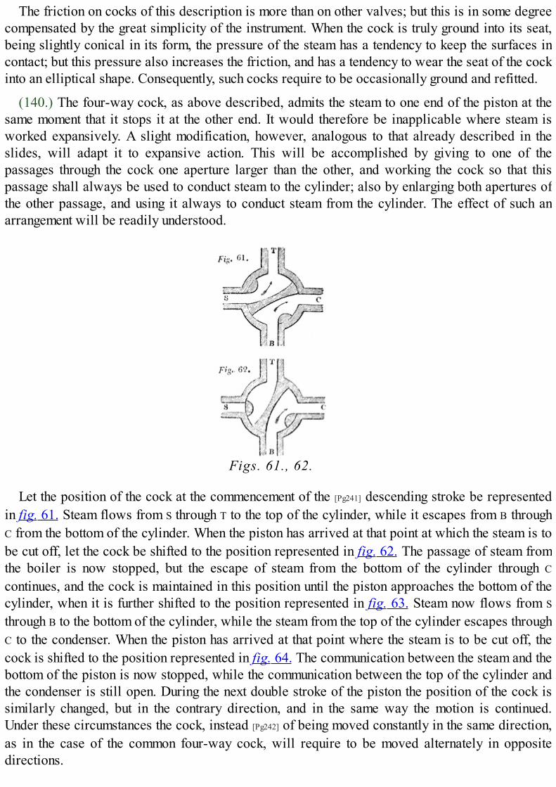
The friction on cocks of this description is more than on other valves; but this is in some degreecompensated by the great simplicity of the instrument. When the cock is truly ground into its seat,being slightly conical in its form, the pressure of the steam has a tendency to keep the surfaces incontact; but this pressure also increases the friction, and has a tendency to wear the seat of the cockinto an elliptical shape. Consequently, such cocks require to be occasionally ground and refitted.
(140.) The four-way cock, as above described, admits the steam to one end of the piston at thesame moment that it stops it at the other end. It would therefore be inapplicable where steam isworked expansively. A slight modification, however, analogous to that already described in theslides, will adapt it to expansive action. This will be accomplished by giving to one of thepassages through the cock one aperture larger than the other, and working the cock so that thispassage shall always be used to conduct steam to the cylinder; also by enlarging both apertures ofthe other passage, and using it always to conduct steam from the cylinder. The effect of such anarrangement will be readily understood.
Figs. 61., 62.
Let the position of the cock at the commencement of the [Pg241] descending stroke be representedin fig. 61. Steam flows from S through T to the top of the cylinder, while it escapes from B throughC from the bottom of the cylinder. When the piston has arrived at that point at which the steam is tobe cut off, let the cock be shifted to the position represented in fig. 62. The passage of steam fromthe boiler is now stopped, but the escape of steam from the bottom of the cylinder through C
continues, and the cock is maintained in this position until the piston approaches the bottom of thecylinder, when it is further shifted to the position represented in fig. 63. Steam now flows from S
through B to the bottom of the cylinder, while the steam from the top of the cylinder escapes throughC to the condenser. When the piston has arrived at that point where the steam is to be cut off, thecock is shifted to the position represented in fig. 64. The communication between the steam and thebottom of the piston is now stopped, while the communication between the top of the cylinder andthe condenser is still open. During the next double stroke of the piston the position of the cock issimilarly changed, but in the contrary direction, and in the same way the motion is continued.Under these circumstances the cock, instead [Pg242] of being moved constantly in the same direction,as in the case of the common four-way cock, will require to be moved alternately in oppositedirections.

Figs. 63., 64.
PISTONS.
(141.) The office of a piston being to divide a cylinder into two compartments by a movablepartition which shall obstruct the passage of any fluid from one compartment to the other, it isevident that the two conditions which such an instrument ought to fulfil are, first, that the contact ofits sides with the surface of the cylinder shall be so close and tight throughout its entire play that nosteam or other fluid can pass between them; secondly, that it shall be so free from friction,notwithstanding this necessary tightness, that it shall not absorb any injurious quantity of themoving power.
Since, however accurately the surfaces of the piston and cylinder may be constructed, there willalways be in practice more or less imperfection of form, it is evident that the contact of the surfaceof the piston with the cylinder throughout the stroke can only be maintained by giving to thecircumference of the piston sufficient elasticity to accommodate itself to such inequalities of form.The substance, whatever it may be, used for this purpose, and by which the piston is surrounded, iscalled packing.
In steam pistons the material used for packing must be such as is capable of resisting the unitedeffects of heat and moisture. Hence leather and other animal substances are inapplicable.
The packing used for steam pistons is therefore of two kinds, vegetable packing, usually hemp,or metallic packing.
The common hemp-packed piston has been already in part described (79.). The bottom of thepiston is a circular plate just so much less in diameter than the cylinder as is sufficient to allow itsfree motion in ascending and descending. A little above its lowest point this plate begins graduallyto diminish in thickness, until its diameter is reduced to from one to two inches less than that of thecylinder, leaving therefore around [Pg243] it a hollow space, as represented in fig. 65. The cover ofthe piston is a plate similarly formed, being in like manner gradually reduced in thicknessdownwards, so as to correspond with the lower plate. In the hollow space which thus surroundsthe piston a packing of unspun hemp or soft rope, called gasket, is introduced by winding it roundthe piston so as to render it an even and compact mass. When the space is thus filled up, the top ofthe piston is attached to the bottom by screws. The curved form of the space within which thehempen packing is confined is such that when the screws are tightened, that part of the packingwhich is nearest to the top and bottom of the piston is forced against the cylinder, so as to produceupon the two parallel rings as much pressure as is necessary to render it steam-tight. When by usethe packing is worn down so as to produce leakage, the cover of the cylinder must be removed,and the screws connecting the top and bottom of the piston tightened: this will force out the packing

and render the piston steam-tight. This packing is lubricated by melted tallow let down upon thepiston from the funnel inserted in the top of the cylinder, furnished with a stop-cock to prevent theescape of steam. The lower end of the piston-rod is formed slightly conical, the thickest part of thecone being downward. It is passed up through the piston, and a nut or wedge between the top andbottom is inserted so as to secure the piston in its position upon the rod.
Fig. 65.
The process of removing the top of the cylinder for the purpose of tightening the screws in thepiston is one of so laborious a nature, that the men entrusted with the superintendence of thesemachines are tempted to allow the engine to work notwithstanding injurious leakage at the piston,rather than incur the labour of tightening the screws as often as it is necessary to do so.
To avoid this inconvenience, the following method of [Pg244] tightening the packing of the pistonwithout removing the lid of the cylinder, was contrived by Woolf. The head of each of the screwswas formed into a toothed pinion, and as these screws were placed at equal distances from thecentre of the piston, these several pinions were driven by a large toothed wheel, revolving on thepiston-rod as an axis. By such an arrangement it is evident that if any one of the screws be turned, alike motion will be imparted to all the others through the medium of the large central wheel. Woolfaccordingly formed, on the head of one of the screws, a square end. When the piston was broughtto the top of the cylinder, this square end entered an aperture made in the under side of the cover ofthe cylinder. This aperture was covered by a small circular piece screwed into the top of thecylinder, which was capable of being removed so as to render the square head of the screwaccessible. When this was done, a proper key being applied to the square head of the screw, it wasturned; and by being turned, all the other screws were in like manner moved. In this way, instead ofhaving to remove the cover of the cylinder, which in large cylinders was attended with greatlabour and loss of time, the packing was tightened by merely unscrewing a piece in the top of thecylinder not much greater in magnitude than the head of one of the screws.
This method was further simplified by causing the great circular wheel already described tomove upon the piston-rod, not as an axis, but as a screw, the thread being cut upon a part of thepiston-rod which worked in a corresponding female screw cut upon the central plate. By suchmeans, the screw whose head was let into the cover of the cylinder which turned, would cause thiscircular plate to be pressed downwards by the force of the screw constructed on the piston-rod.This circular plate thus pressed downwards, acted upon pins or plugs which pressed together thetop and bottom of the cylinder in the same manner as they were pressed together by the screwsconnecting them as already described.
METALLIC PISTONS.
(142.) The notion of constructing a piston so as to move steam-tight in the cylinder without theuse of packing of vegetable [Pg245] matter was first suggested by the Rev. Mr. Cartwright, a

gentleman well known for other mechanical inventions. A patent was granted in 1797 for a newform of steam engine, in which he proposed to use the vapour of alcohol to work the piston insteadof the steam of water: and since the principle of the engine excluded the use of lubrication by oil ortallow, he substituted a piston formed of metallic rings pressed against the surface of the cylinderby springs, so as to be maintained in steam-tight contact with it, independently either of packing orlubrication. Although the engine for which this form of piston was intended never came intopractical use, yet it is so simple and elegant in its structure, and forms a link so interesting in thehistory of the steam engine, that some explanation of it ought not to be omitted in this work.
The steam-pipe from the boiler is represented cut off at B (fig. 66.); T is a spindle-valve, foradmitting steam above the piston, and R is a spindle-valve in the piston; D is a curved pipe forminga communication between the cylinder and the condenser, which is of very peculiar construction.Cartwright proposed effecting a condensation without a jet, by exposing the steam to contact with avery large quantity of cold surface. For this purpose, he formed his condenser by placing twocylinders nearly equal in size, one within the other, allowing the water of the cold cistern in whichthey were placed to flow through the inner cylinder, and to surround the outer one. Thus, the thinspace between the two cylinders formed the condenser.
Fig. 66.

The air-pump is placed immediately under the cylinder, and the continuation of the piston-rodworks its piston, which is solid and without a valve. F is the pipe from the condenser to the air-pump, through which the condensed steam is drawn off through the valve G on the ascent of thepiston, and on the descent this is forced through a tube into a hot well H, for the purpose of feedingthe boiler through the feed-pipe I. In the top of the hot well H is a valve which opens inwards, andis kept closed by a ball floating on the surface of the liquid. The pressure of the condensed airabove the surface of the liquid in H forces it through I into the boiler. When the air accumulates intoo great a degree [Pg246] in H, the surface of the liquid is pressed so low that the ball falls andopens the valve, and allows it to escape. The air in H is that which is pumped from the condenserwith the liquid, and from which it was disengaged.
Let us suppose the piston at the top of the cylinder: it strikes the tail of the valve T, and raises it,while the stem of the piston-valve R strikes the top of the cylinder, and is pressed into its seat. Afree communication is at the same time open between the cylinder, below the piston and thecondenser, through the tube D. The pressure of the steam [Pg247] thus admitted above the piston actingagainst the vacuum below it, will cause its descent. On arriving at the bottom of the cylinder, thetail of the piston-valve R will strike the bottom, and it will be lifted from its seat, so that acommunication will be opened through it with the condenser. At the same moment, a projectingspring K, attached to the piston-rod, strikes the stem of the steam-valve T, and presses it into itsseat. Thus while the further admission of steam is cut off, the steam above the piston flows into thecondenser, and the piston being relieved from all pressure, is drawn up by the momentum of thefly-wheel, which continues the motion it received from the descending force. On the arrival of thepiston again at the top of the cylinder, the valve T is opened and R closed, and the piston descendsas before, and so the process is continued.
The mechanism by which motion is communicated from the piston to the fly-wheel is peculiarlyelegant. On the axis of the fly-wheel is a small wheel with teeth, which work in the teeth of anotherlarger wheel L. This wheel is turned by a crank, which is worked by a cross-piece attached to theend of the piston-rod. Another equal-toothed wheel M is turned by a crank, which is worked by theother end of the cross-arm attached to the piston-rod.
One of the peculiarities of this engine is, that the liquid which is used for the production ofsteam in the boiler circulates through the machine without either diminution or admixture with anyother fluid, so that the boiler never wants more feeding than what can be supplied from the hotwell H. This circumstance forms an important feature in the machine, as it allows of ardent spiritsbeing used in the boiler instead of water, which, since they boil at low heats, promised a saving offuel. The inventor proposed that the engine should be used as a still, as well as a mechanicalpower, in which case the whole of the fuel would be saved.
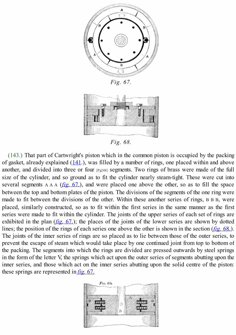
Fig. 67.
Fig. 68.
(143.) That part of Cartwright's piston which in the common piston is occupied by the packingof gasket, already explained (141.), was filled by a number of rings, one placed within and aboveanother, and divided into three or four [Pg248] segments. Two rings of brass were made of the fullsize of the cylinder, and so ground as to fit the cylinder nearly steam-tight. These were cut intoseveral segments A A A (fig. 67.), and were placed one above the other, so as to fill the spacebetween the top and bottom plates of the piston. The divisions of the segments of the one ring weremade to fit between the divisions of the other. Within these another series of rings, B B B, wereplaced, similarly constructed, so as to fit within the first series in the same manner as the firstseries were made to fit within the cylinder. The joints of the upper series of each set of rings areexhibited in the plan (fig. 67.); the places of the joints of the lower series are shown by dottedlines; the position of the rings of each series one above the other is shown in the section (fig. 68.).The joints of the inner series of rings are so placed as to lie between those of the outer series, toprevent the escape of steam which would take place by one continued joint from top to bottom ofthe packing. The segments into which the rings are divided are pressed outwards by steel springsin the form of the letter V, the springs which act upon the outer series of segments abutting upon theinner series, and those which act on the inner series abutting upon the solid centre of the piston:these springs are represented in fig. 67.

Fig. 69.
(144.) An improved form was given to the metallic piston by Barton. Barton's piston consists ofa solid cylinder of cast iron, represented at A in section in fig. 69., and in plan in [Pg249] fig. 70. Inthe centre of this is a conical hole, increasing in magnitude downwards, to receive the piston-rod,in which the latter is secured by a cross-pin B. A deep groove, square in its section, is formedaround the piston, so that while the top and bottom of the piston form circles equal in magnitude tothe section of the cylinder, the intermediate part of the body of the piston forms a circle less thanthe former by the depth of the groove. Let a ring of brass, cast iron, or cast steel, be made tocorrespond in magnitude and form with this groove, and let it be divided as represented in fig. 70.,into four segments C C C C, and four corresponding angular pieces D D D D. Let the groove whichsurrounds the piston be filled by the four segments with the four wedge-like angular pieces withinthem, and let the latter be urged against the former by eight spiral springs, as represented in fig. 69.and fig. 70. These springs will abut against the solid centre by the piston, and will urge thesegments C against the cylinder. The spiral springs which urge the wedges are confined in theiraction by steel pins which pass through their centre, and by being [Pg250] confined in cylindricalcavities worked into the wedges and into corresponding parts of the solid centre of the piston, asthe segments C wear, the springs urge the wedges outwards, and the points of the latter protruding,are gradually worn down so as to fill up the spaces left between the segments, and thus to completethe outer surface of the piston.
Fig. 70.
Various other forms of metallic pistons have been proposed, but as they do not differ materiallyin principle from those we have just described, it will not be necessary here to describe them.

ENGINE AT THE CITY SAW MILLS.
FURNACE AT THE CITY SAW MILLS.

CHAP. IX.
[Pg251]
TOC INX
CONSTITUENTS OF COAL.—PROCESS OF COMBUSTION.—HEAT EVOLVED IN IT.—FORM AND STRUCTUREOF BOILER.—WAGGON BOILER.—FURNACE.—METHOD OF FEEDING IT.—COMBUSTION OF GAS INFLUES.—CONSTRUCTION OF GRATE AND ASH-PIT.—MAGNITUDE OF HEATING SURFACE OF BOILER.—STEAM-SPACE AND WATER-SPACE IN BOILER.—POSITION OF FLUES.—METHOD OF FEEDING BOILER.—LEVEL GAUGES.—SELF-REGULATING FEEDERS.—STEAM-GAUGE.—BAROMETER-GAUGE.— INDICATOR.—COUNTER.—SAFETY-VALVE.—FUSIBLE PLUGS.—SELF-REGULATING DAMPER.—SELF-REGULATINGFURNACE.—POWER AND DUTY OF ENGINES.—HORSE-POWER OF STEAM ENGINES.—EVAPORATIONPROPORTIONAL TO HORSE-POWER.—SOURCES OF LOSS OF POWER.—ABSENCE OF GOOD PRACTICALRULES FOR POWER.—COMMON RULES FOLLOWED BY ENGINE MAKERS.—DUTY DISTINGUISHED FROMPOWER.—DUTY OF BOILERS.—PROPORTION OF STROKE TO DIAMETER OF CYLINDER.—DUTY OFENGINES.—CORNISH SYSTEM OF INSPECTION.—ITS GOOD EFFECTS.—HISTORICAL DETAIL OF THEDUTY OF CORNISH ENGINES.
(145.) The machinery which has been explained in the preceding chapters, consisting of thecylinder with its passages and valves, the piston-rod, parallel motion, beam, connecting-rod andcrank, together with the condenser, air-pump, and other appendages, having no source of movingpower in themselves, must be regarded as mere instruments by which the mechanical effectdeveloped by the furnace and the boiler is transmitted to the working point and so [Pg252] modifiedas to be adapted to the uses to which the machine is applied. The boiler is at once a magazine inwhich the moving power is stored in sufficient quantity to supply the demands of the engine and anapparatus in which that power is fabricated. The mechanical effect evolved in the conversion ofwater into steam by heat, is the process by which the power of the steam-engine is produced, andspace is provided in the boiler, capacious enough to contain as much steam as is necessary for theengine, besides a sufficient quantity of water to continue that supply undiminished, notwithstandingthe constant drafts made upon it by the cylinder: even the water itself, from the evaporation ofwhich the mechanical power is produced, ought to be regarded as an instrument by which the effectof the heat of the combustible is rendered mechanically efficient, inasmuch as the same heat,applied not only to other liquids but even to solids, would likewise be productive of mechanicaleffects. The boiler and its furnace are therefore parts of the steam-engine, the construction andoperation of which are entitled to especial attention.
(146.) COAL, the combustible almost universally used in steam-engines, is a substance, theprincipal constituents of which are carbon and hydrogen, occasionally mixed with sulphur in asmall proportion, and earthy incombustible matter. In different sorts of coal the proportions ofthese constituents vary, but in coal of good quality about three quarters of the whole weight of thecombustible is carbon.
When carbon is heated to a temperature of about 700° in an atmosphere of pure oxygen, it willcombine chemically with that gas, and the product will be the gas called carbonic acid. Thevolume of carbonic acid produced by this combination, will be exactly equal to that of the oxygencombined with the carbon, and therefore the weight of a given volume of the gas will be increasedby the weight of carbon which enters the combination. It is found that two parts by weight ofoxygen combined with three of carbon, form carbonic acid. The weight of the carbonic acid,therefore, produced in the combustion, will be greater than the weight of the oxygen, bulk for bulk,

in the proportion of five to two, the volume being the same and the gases being [Pg253] compared atthe same temperatures and under equal pressures. In this combination heat is evolved in very largequantities. This effect arises from the heat previously latent in the carbon and oxygen beingrendered sensible in the process of combustion. The carbonic acid proceeding from thecombustion is by such means raised to a very high temperature, and the carbon during the processacquires a heat so intense as to become luminous; no flame, however, is produced.
Hydrogen, heated to a temperature of about 1000°, in contact with oxygen will combine with thelatter, and a great evolution of heat will attend the process; the gases will be rendered luminous,and flame will be produced. The product of this process will be water, which being exposed to theintense heat of combustion, will be immediately converted into steam. Hydrogen combines witheight times its own weight of oxygen, producing nine times its own weight of water.
Hydrogen gas is, however, not usually disengaged from coal in a simple form, but combinedchemically with a certain portion of carbon, the combination being called carburetted hydrogen.Pure hydrogen burns with a very faintly luminous blue flame, but carburetted hydrogen gives thatbright flame occasionally having an orange or reddish tinge, which is seen to issue from burningcoals: this is the gas used for illumination, being expelled from the coal by the process of coking,and conducted to the various burners through proper pipes.
The sulphur, which in a very small proportion is contained in coals, is also combustible, andcombines in the process of combustion with oxygen, forming sulphurous acid: it is also sometimesevolved in combination with hydrogen, forming sulphuretted hydrogen.
Atmospheric air consists of two gases, azote and oxygen, mixed together in the proportion offour to one; five cubic feet of atmospheric air consisting of four cubic feet of azote and one ofoxygen. Any combustible will combine with the oxygen contained in atmospheric air, if raised to atemperature somewhat higher than that which is necessary to cause its combustion in anatmosphere of pure oxygen.
If coals, therefore, or other fuel exposed to atmospheric [Pg254] air, be raised to a sufficiently hightemperature, their combustible constituents will combine with the oxygen of the atmospheric air,and all the phenomena of combustion will ensue. In order, however, that the combustion should becontinued, and should be carried on with quickness and activity, it is necessary that the carbonicacid, and other products, should be removed from the combustible as they are produced, and freshportions of atmospheric air brought into contact with it; otherwise the combustible would soon besurrounded by an atmosphere composed chiefly of carbonic acid to the exclusion of atmosphericair, and therefore of uncombined oxygen, and consequently the combustion would cease, and thefuel be extinguished. To maintain the combustion, therefore, a current of atmospheric air must beconstantly carried through the fuel: the quantity and force of this current must depend on thequantity and quality of the fuel to be consumed. It must be such that it shall supply sufficient oxygento the fuel to maintain the combustion, and not more than sufficient, since any excess would beattended with the effect of absorbing the heat of combustion, without contributing to themaintenance of that effect.
Heat is communicated from body to body in two ways, by radiation and by contact.
Rays of heat issue from a heated body, and are dispersed through the surrounding space in amanner, and according to laws, similar to those which govern the radiation of light. The heat thusradiated meeting other bodies is imparted to them, and penetrates them with more or less facility

according to their physical qualities.
A heated body also brought into contact with another body of lower temperature, communicatesheat to that other body, and will continue to do so until the temperature of the two bodies in contactshall be equalised. Heat proceeds from fuel in a state of combustion in both these ways: the heatedfuel radiates heat in all directions around it, and the heat thus radiated will be imparted to all partsof the furnace which are exposed to the fuel.
The gases, which are the products of the combustion, escape from the fuel at a very hightemperature, and consequently, in acquiring that temperature they absorb a considerable [Pg255]
quantity of the heat of combustion. But besides the gases actually formed in the process ofcombustion, the azote forming four fifths of the air carried through the fuel to support thecombustion, absorbs heat from the combustible, and rises into the upper part of the furnace at ahigh temperature. These various gases, if conducted directly to the chimney, would carry off withthem a considerable quantity of the heat. Provision should therefore be made to keep them incontact with the boiler such a length of time as will enable them to impart such a portion of the heatwhich they have absorbed from the fuel, as will still leave them at a temperature sufficient, and notmore than sufficient, to produce the necessary draft in the chimney.
(147.) The forms of boiler which have been proposed as the most convenient for the attainmentof all these requisite purposes have been very various. If strength alone were considered, thespherical form would be the best; and the early boilers were very nearly hemispheres, placed on aslightly concave base. The form adopted by Watt, called the waggon boiler, consists of a semi-cylindrical top, flat perpendicular sides, flat ends, and a slightly concave bottom. The steamintended to be used in boilers of this description did not exceed the pressure of the externalatmosphere by more than from 3 to 5 lbs. per square inch; and the flat sides and ends, thoughunfavourable to strength, could be constructed sufficiently strong for this purpose. In a boiler ofthis sort, the air and smoke passing through the flues that are carried round it, are in contact at oneside only with the boiler. The brickwork, or other materials forming the flue, must therefore benon-conductors of heat, that they may not absorb any considerable portion of heat from the airpassing in contact with them. A boiler of this form is represented in fig. 71.

Fig. 71
The grate and a part of the flues are rendered visible by the removal of a portion of thesurrounding masonry in which the boiler is set. The interior of the boiler is also shown by cuttingoff one half of the semi-cylindrical roof. A longitudinal vertical section is shown in fig. 72., and across section in fig. 73. A horizontal section taken above the level of the grate, and below the levelof the water in the boiler, showing [Pg256] the course of the flues, is given in fig. 74. Thecorresponding parts in all the figures are marked by the same letters.

Fig. 72.
The door by which fuel is introduced upon the grate is represented at A, and the door leading tothe ash-pit at B. The fire bars at C slope downwards from the front at an angle of about 25°, givinga tendency to the fuel to move from the front towards the back of the grate. The ash-pit D isconstructed of such a magnitude, form, and depth, as to admit a current of atmospheric air to thegrate-bars, sufficient to sustain the combustion. The form of the ash-pit is usually wide below,contracting towards the top.
The fuel when introduced at the fire-door A, should be laid on that part of the grate nearest to thefire-door, called the dead plates: there it is submitted to the process of coking, by which the gasesand volatile matter which it contains are expelled, and being carried by a current of air, admitted[Pg257] through small apertures in the fire-door over the burning fuel in the hinder part of the grate,they are burnt. When the fuel in front of the grate has been thus coked, it is pushed back, and a freshfeed introduced in front. The coal thus pushed back soon becomes vividly ignited, and bycontinuing this process, the fuel spread over the grate is maintained in the most active state ofcombustion at the hinder part of the grate. By such an arrangement, the smoke produced by thecombustion of the fuel may be burnt before it enters the flues. The flame and heated air proceedingfrom the burning fuel arising from the grate, and rushing towards the back of the furnace, passesover the fire-bridge E, and is carried through the flue F which passes under the boiler. This flue(the cross section of which is shown in fig. 73., by the dark shade put under the boiler) is verynearly equal in width to the bottom of the boiler, the space at the bottom of the boiler, near thecorners, being only what is sufficient to give the weight of the boiler support on the masonryforming the [Pg258] sides of the flue. The bottom of the boiler being concave, the flame and heated airas they pass along the flue rise to the upper part by the effects of their high temperature, and lickthe bottom of the boiler from the fire-bridge at E to the further end G.

Fig. 73.
At G the flue rises to H, and turning to the side of the boiler at I I, conducts the flame in contactwith the side from the back to the front; it then passes through the flue K across the front, andreturns to the back by the other side [Pg259] flue L. The side flue is represented, stripped of themasonry, in fig. 71., and also appears in the plan in fig. 74., and in the cross section in fig. 73. Thecourse of the air is represented in fig. 74. by the arrows. From the flue L the air is conducted intothe chimney at M.
Fig. 74.
By such an arrangement, the flame and heated air proceeding from the grate are made tocirculate round the boiler, and the length and magnitude of the flues through which it is conductedshould be such, that when it shall arrive at the chimney its temperature shall be reduced, as nearlyas is consistent with the maintenance of draught in the chimney, to the temperature of the water withwhich it is in contact.
The method of feeding the furnace, which has been described above, is one which, if conducted

with skill and care, would produce a much more perfect combustion of the fuel than would attendthe common method of filling the grate from the back to the front with fresh fuel, whenever thefurnace is fed. This method, however, is rarely observed in the management of the furnace. Itrequires the constant attention of the stokers (such is the name given to those who feed thefurnaces). The fuel must be supplied, not in large quantities, and at distant intervals, but in smallquantities and more frequently. On the other hand, the more common practice is to allow the fuel onthe grate to be in a great degree burned away, and then to heap on a large quantity of fresh fuel,covering over with it the burning fuel from the back to the front of the grate. When this is done, theheat of the ignited coal acting upon the fresh fuel introduced, expels the gases combined with itand, mixed with these, a quantity of carbon, in a state of minute division, forming an opaque blacksmoke. This is carried through the flues and drawn up the chimney. The consequence is, that notonly a quantity of solid fuel is sent out of the chimney unconsumed, but the hydrogen and othergases also escape unburned, and a proportional waste of the combustible is produced; besideswhich, the nuisance of an atmosphere filled with smoke ensues. Such effects are visible to all whoobserve the chimneys of steam-vessels, while the engine is in operation. When the furnaces arethus filled with fresh fuel, a large volume of [Pg260] dense black smoke is observed to issue from thechimney. This gradually subsides as the fuel on the grate is ignited, and does not reappear until afresh feed is introduced.
This method of feeding, by which the furnace would be made to consume its own smoke, and thecombustion of the fuel be rendered complete, is not however free from counteracting effects. Inordinary furnaces the feed can only be introduced by opening the fire-doors, and during the timethe fire-doors are opened a volume of cold air rushes in, which passing through the furnace iscarried through the flues to the chimney. Such is the effect of this in lowering the temperature of theflues, that in many cases the loss of heat occasioned is greater than any economy of fuel obtainedby the complete consumption of smoke. Various methods, however, may be adopted by which fuelmay be supplied to the grate without opening the fire-doors, and without disturbing the supply ofair to the fire. A hopper built into the front of the furnace, with a moveable bottom or valve, bywhich coals may be allowed to drop in from time to time upon the front of the grate, wouldaccomplish this.
(148.) In order to secure the combustion of the gases evolved from the coals placed in the frontof the grate, it is necessary that a supply of atmospheric air should be admitted with them over theburning fuel. This is effected by small apertures or regulators, provided in the fire-doors, governedby sliding-plates, by which they may be opened or closed to any required extent.
A patent has recently been granted to Mr. Williams, one of the directors of the City of DublinSteam Navigation Company, for a method of consuming the unburned gases which escape from thegrate, and are carried through the flues. This method consists in introducing into the flue tubesplaced in a vertical position, the lower ends of which being inserted in the bottom of the flue aremade to communicate with the ash-pit, and the upper ends of which are closed. The sides and topsof these tubes are pierced with small holes, through which atmospheric air drawn from the ash-pitissues in jets. The oxygen supplied by this air immediately combines with the carburettedhydrogen, which [Pg261] having escaped from the furnace unburned is carried through the flues at asufficient temperature to enter into combination with the oxygen admitted through holes in thetubes. A number of jets of flame thus proceed from these holes, having an appearance similar to theflame of a gas-lamp.

It is evident that such tubes must be inefficient unless they are placed in the flues so near thefurnace, that the temperature of the unburned gases shall be sufficiently high to produce theircombustion.
(149.) The magnitude of the grate and ash-pit must be determined by the rate at which theevaporation is required to be conducted in the boiler and the quality of the fuel. It must be a matterof regret, that the proportions of the various parts of steam-engines, with their boilers and furnaces,have not been determined by any exact or satisfactory experiments; and those who project andmanufacture the engines themselves, are not less in ignorance on those points than others. Withcoals of the common quality a certain average proportion must exist between the necessarymagnitude of the grate-surface and the quantity of water to be evaporated in a given time in theboiler. But what that proportion is for any given quality of fuel, is at present unascertained. Eachengine-maker follows his own rule, and the rule thus followed is in most cases a matter of bareconjecture, unsupported by any experimental evidence. Some engine-makers will allow a squarefoot of grate-surface for every cubic foot of water per hour, which is expected to be evaporated inthe boiler; others allow only half a square foot: and practice varies between these limits.Bituminous coals which melt and cake, and which burn with much flame and smoke, must bespread more thinly on the grate than other descriptions of fuel, otherwise a considerable quantity ofcombustible gases would be dismissed into the flues unburnt. Such coals therefore, othercircumstances being the same, require a larger portion of grate-surface; and the same may be saidof coals which produce clinkers in their combustion, and form lumps of vitrified matter on thegrate, by which the spaces between the grate-bars are speedily closed up. When such fuel is used,the grate-bars require to be frequently raked [Pg262] out, otherwise the spaces between them beingobstructed, the draught would become insufficient for the due combustion of the fuel.
To facilitate the raking out of the grate, the bars are placed with their ends towards the fire-door: they are usually made of cast-iron, from two to two inches and a half wide on the uppersurface, with intervals of nearly half an inch between them. The bars taper downwards, their undersurfaces being much narrower than their upper, the spaces between them thus widening, tofacilitate the fall of the ashes between them. The grate-bars slope downwards from the front to theback. The height of the centre of the bottom of the boiler, above the front of the grate, is usuallyabout two feet, and about three feet above the back of it. The concave bottom of the boiler,however, brings its surfaces at the slide closer to the grate.
(150.) Between the evaporating power of the boiler, and the magnitude of surface it exposes tothe action of the furnace, there is a relation which, like that of the grate surface, has never beenascertained by any certain or satisfactory experimental investigation; much less have the differentdegrees of efficiency attending different parts of the boiler-surface been determined. That part ofthe surface of the boiler immediately over and around the grate, is exposed to the immediateradiation of the burning fuel, and is therefore probably the most efficient in the production ofsteam. The tendency of flame and heated air to rise, would naturally bring them in the flues intocloser contact with those parts of the boiler-surface which are horizontal in their position, andwhich form the tops of the flues, than with those which are lateral or vertical in their position, andwhich form the sides of the flues. In a boiler constructed like that already described, the flue-surface therefore, which would be most efficient, would be the concave bottom of the boilerextending from the fire-bridge to its remote end. In some boilers, especially those in which steamof high pressure is produced, the form is cylindrical, the middle flue being formed into an

elliptical tube the greater axis of which is horizontal from end to end of the boiler. It seemsdoubtful, however, [Pg263] whether in such a boiler the heat produces any useful effect on the waterbelow the flue, the water above being always at a higher temperature, and therefore lighter thanthat below, and consequently no currents being established between the upper and lower strata ofthe water.
It was considered by Mr. Watt, but we are not aware on what experimental grounds, that fromeight to ten square feet of heating surface were sufficient to produce the evaporation of one cubicfoot of water per hour. The practice of engine-makers since that time has been to increase theallowance of heating surface for the same rate of evaporation. Engine-builders have varied verymuch in this respect, some allowing twelve, fifteen, and even eighteen square feet of surface forthe same rate of evaporation. It must, however, still be borne in mind, that whether this increasedallowance did or did not produce the actual evaporation imputed to it, has not been, as far as weare informed, ever accurately ascertained. The production of a given rate of evaporation by amoderate heat diffused over a larger surface, rather than by a fiercer temperature confined to asmaller surface, is attended with many practical advantages. The plates of the boiler acted upon bythe fire are less exposed to oxydisation, and the boiler will be proportionally more durable.
(151.) Besides presenting to the action of the fire a sufficient surface to produce steam at therequired rate, the capacity of the boiler must be proportioned to the quantity of water to beevaporated. The space within the boiler is appropriated to a twofold purpose: 1st, To contain thewater to be evaporated; 2dly, To contain a quantity of ready made steam for the supply of thecylinder. If the space appropriated to the steam did not bear a considerable proportion to themagnitude of the cylinder, the momentary expansion of the steam passing to the cylinder from theboiler at each stroke would reduce the pressure of the steam in a great proportion, and unless thepressure in the boiler were considerably greater than that which the steam is intended to have inthe cylinder, the pressure in the latter would be reduced below the proper amount. The proportionof the [Pg264] steam space in the boiler to the magnitude of the cylinder has been very variouslyestimated, nor can it be said that any practical rule of a general kind has been adopted. It is held bysome that the steam-space will be sufficient if it contain five times the quantity of steam consumedat each stroke, while others maintain that it should contain at least ten times that quantity, andopinions vary between these limits.
(152.) The proportion of water-space in the boiler to its evaporating power should also beregulated, so that the introduction of the feed at a comparatively low temperature may not undulychill the water in the boiler. Supposing the feed to be introduced in a low pressure boiler at thetemperature of 100°, and that the necessary temperature within the boiler be 225°, the quantity ofwater it contains should be about five times the quantity evaporated, and therefore also five timesthe quantity introduced through the feed per hour. For every cubic foot of water per hour therefore,intended to be evaporated by the boiler, water-space for five cubic feet should be provided. It is,however, right to repeat that this (like almost every other so called rule) is the result not of anyexact general calculation, but one deduced from the custom which has obtained among themanufacturers of steam-engines.
(153.) The surface of the water in the boiler should always be above the range of the flues.When the heated air in the flues acts upon a part of the boiler within which water is contained, thewater within receiving an increased temperature becomes, bulk for bulk, lighter than the strata ofwater above it, and ascends. It is replaced by the descending strata, which, in their turn receiving

increased temperature, rise to the surface; or if the action of the heat convert the water into steam,the bubbles of steam rise to the surface, fresh portions of water continually coming into contactwith the boiler-plates on which the heated air or flame acts. By this process the boiler-plates arecontinually cooled, either by being successively washed by water at a lower temperature, or by theheat taken from them becoming latent in the steam bubbles formed in contact with them. But if theheat act [Pg265] upon a part of the boiler containing steam within it, which steam being a slowrecipient of heat, and no currents being established, nor any phenomenon produced in which heat isrendered latent, the heat of the fire communicated to the boiler-plates accumulates in them, andraises their temperature to an injurious degree. The plates may by this means be softened, so as tocause the boiler to burst, or the difference between the expansion of the highly heated plates thusexposed to fire in contact with steam and that of the plates which are cooled by contact with water,may cause the joinings of the boiler-plates to open, and the boiler to leak. By whatever means,therefore, the boiler be fed, care should be taken that the evaporation should not be allowed toreduce the level of the water in it below the highest flue.
(154.) As the water by which the boiler is fed must always have a much lower temperature thanthat at which the boiler is maintained, the supply of the feed will have a constant tendency to lowerthe temperature of the water, and this tendency will be determined by the proportion between themagnitude of the feed and the quantity of water in the boiler.
Since it is requisite that the level of the water in the boiler shall not suffer any considerablechange, it is evident that the magnitude of the feed must be equal to the quantity of waterevaporated. If it were less, the level of the water would continually fall by reason of the excess ofthe evaporation over the feed; and if it were greater, the level would rise by the accumulation ofwater in the boiler. If therefore the quantity of water-space allowed in the boiler be five times thevolume of water evaporated per hour, the quantity introduced by the feed per hour, whethercontinuously or at intervals, must be of the same amount. Since the process of evaporation iscontinuous, the variation of level of water in the boiler will be entirely dependent on the intervalsbetween the successive feeds. If the feed be continuous, and always equal to the evaporation, thenthe level of the water in the boiler will undergo no change; but if while the evaporation iscontinuous the feed be made at intervals, then the change of level of water in the boiler as [Pg266]
well as its change of temperature, will be subject to a variation proportional to the intervalsbetween the successive feeds. It is manifest, therefore, that the feed should either be uninterruptedor be supplied at short intervals, so that the change of level and temperature of the water in theboiler should not be considerable.
(155.) Different methods have been, from time to time, suggested for indicating the level of thewater in the boiler. We have already mentioned the two gauge-pipes used in the earlier steam-engines (31.), and which are still generally continued. There are, however, some other methodswhich merit our attention.

Fig. 75.
A weight F (fig. 75.), half immersed in the water in the boiler, is supported by a wire, which,passing steam-tight through a small hole in the top, is connected by a flexible string, or chain,passing over a wheel W, with a counterpoise A, which is just sufficient to balance F when halfimmersed. If F be raised above the water, A being lighter will no longer balance it, and F willdescend pulling up A, and turning the wheel W. If, on the other hand, F be plunged deeper in thewater, A will more than balance it, and will pull it up, so that the only position in which F and A
will balance each other is, when F is half immersed. The wheel W is so adjusted, that when twopins placed on its rim are in the horizontal position, the water is at its proper level. Consequentlyit follows, that if the water rise above this level, the weight F is lifted and A falls, so that the pinscome into another position. If, on the other hand, the level of the water fall, F falls and A rises, sothat the pins assume a different position. Thus, in general, the position of the pins becomes anindication of the quantity of water in the boiler.
(156.) Another method is to place a glass tube (fig. 76.), with one end T entering the boilerabove the proper level, and the other end T′ entering it below the proper level. It must [Pg267] beevident that the water in the tube will always stand at the same level as the water in the boiler,since the lower part has a free communication with that water, while the surface is submitted to thepressure of the same steam as the water in the boiler. This and the last-mentioned gauge have theadvantage of addressing the eye of the engineer at once, without any adjustment; whereas thegauge-cocks must be both opened, whenever the depth is to be ascertained.
Fig. 76.
These gauges, however, require the frequent attention of the engine-man; and it becomesdesirable either to find some more effectual means of awakening that attention, or to render thesupply of the boiler independent of any attention. In order to enforce the attention of the engine-manto replenish the boiler when partially exhausted by evaporation, a tube was sometimes inserted atthe lowest level to which it was intended that the water should be permitted to fall. This tube wasconducted from the boiler into the engine-house, where it terminated in a mouth-piece or whistle,so that whenever the water fell below the level at which this tube was inserted in the boiler, thesteam would rush through it, and issuing with great velocity at the mouth-piece, would summon the

engineer to his duty with a call that would rouse him even from sleep.
Fig. 77.
(157.) In the most effectual of these methods, the task of replenishing the boiler should still beexecuted by the engineer; and the utmost that the boiler itself was made to do, was to give duenotice of the necessity for the supply of water. The consequence was, among other inconveniences,that the level of the water was subject to constant variation.
To remedy this a method has been invented, by which [Pg268] the engine is made to feed its ownboiler. The pipe G (fig. 77.), which leads from the hot water pump, terminates in a small cistern Cin which the water is received. In the bottom of this cistern, a valve V is placed, which opensupwards, and communicates with a feed-pipe, which descends into the boiler below the level ofthe water in it. The stem of the valve V is connected with a lever turning on the centre D, andloaded with a weight F dipped in the water in the boiler in a manner similar to that described infig. 75., and balanced by a counterpoise A in exactly the same way. When the level of the water inthe boiler falls, the float F falls with it, and pulling down the arm of the lever raises the valve V,and lets the water descend into the boiler from the cistern C. When the boiler has thus beenreplenished, and the level raised to its former place, F will again be raised, and the valve V closedby the weight A. In practice, however, the valve V adjusts itself by means of the effect of the wateron the weight F, so as to permit the water from the feeding-cistern C to flow in a continued stream,just sufficient in quantity to supply the consumption from evaporation, and to maintain the level ofthe water in the boiler constantly the same.
By this arrangement the boiler is made to replenish itself, or, more properly speaking, it is madeto receive such a supply, as that it never wants replenishing, an effect which no effort of attentionon the part of an engine-man could produce. But this is not the only good effect produced by thiscontrivance. A part of the steam which originally left the boiler, and having discharged its duty inmoving the piston, was condensed and reconverted into water, and lodged by the air-pump in thehot well (fig. 77.), is here again restored to the source from which it came, bringing back all theunconsumed portion of its heat preparatory to being once more put in circulation through themachine.
The entire quantity of hot water pumped into the cistern C, is not always necessary for the boiler.A waste-pipe may be provided for carrying off the surplus, which may be turned to any purpose forwhich it may be required; or it may be discharged into a cistern to cool, preparatory to [Pg269] beingrestored to the cold cistern, in case water for the supply of that cistern be not sufficiently abundant.


Fig. 78.
(158.) Another method of arranging a self-regulating feeder is shown in fig. 78. A is a hollowball of metal attached to the end of a lever, whose fulcrum is at B. The other arm of the lever C isconnected with the stem of a spindle-valve, communicating with a tube which receives water fromthe feeding-cistern. Thus, when the level of the water in the boiler subsides, the ball A
preponderating over the weight of the opposite arm, the lever falls, the arm C rises and opens thevalve, and admits the feeding water. This apparatus will evidently act in the same manner and onthe same principles as that already described. [Pg270]
The mouth of the tube by which the feed is introduced should be placed at that part of the boilerwhich is nearest the end of the flues which issue into the chimney. By such means the temperatureof the water in contact with those flues will be lowest at the place where the temperature of theheated air intended to act upon it is also lowest. The difference of the temperatures will thereforebe greater than it would be if the point of the boiler containing water of a higher temperature wasleft in contact with this part of the flue.

Fig. 79.
(159.) It is necessary to have a ready method of ascertaining at all times the pressure of thesteam which is used in working the engine. For this purpose a bent tube containing mercury isinserted into some part of the apparatus, which has free communication with the steam. Let A B C
(fig. 79.) be such a tube. The pressure of the steam forces the mercury down in the leg A B, and upin the leg B C. If the mercury in both legs be at exactly the same level, the pressure of the steammust be exactly equal to that of the atmosphere; because the steam pressure on the mercury in A B
balances the atmospheric pressure on the mercury in B C. If, however, the level of the mercury in BC be above the level of the mercury in B A, the pressure of the steam will exceed that of theatmosphere. The excess of its pressure above that of the atmosphere may be found by observing thedifference of the level of the mercury in the tubes B C and B A, allowing a pressure of one pound oneach square inch for every two inches in the difference of the levels.
If, on the contrary, the level of the mercury in B C should fall below its level in A B, theatmospheric pressure will [Pg271] exceed that of the steam, and the quantity of the excess may beascertained exactly in the same way.
If the tube be glass, the difference of levels of the mercury would be visible; but it is mostcommonly made of iron; and in order to ascertain the level, a thin wooden rod with a float isinserted in the open end of B C, so that the portion of the stick within the tube indicates the distanceof the level of the mercury from its mouth. A bulb or cistern of mercury might be substituted for theleg A B, as in the common barometer. This instrument is called the steam-gauge.
If the steam-gauge be used as a measure of the strength of the steam which presses on the piston,it ought to be on the same side of the throttle-valve (which is regulated by the governor) as thecylinder; for if it were on the same side of the throttle-valve with the boiler, it would not beaffected by the changes which the steam may undergo in passing through the throttle-valve, whenpartially closed by the agency of the governor.
For boilers in which steam of very high pressure is used, as in those of locomotive engines, asteam-gauge, constructed on the above principle, would have inconvenient or impracticable length.In such boilers the pressure of the steam is equal to four or five times that of the atmosphere, toindicate which the column of mercury in the steam-gauge would be four or five feet in height. In

such cases a thermometer-gauge may be used with advantage. The principle of this gauge isfounded on the fact, that between the pressure and temperature of steam produced in contact withwater there is a fixed relation, the same temperature always corresponding to the same pressure. If,therefore, a thermometer be immersed in the boiler which shall show the temperature of the steam,a scale may be attached to it, on which shall be engraved the corresponding pressures. Such gaugesare now very generally used on locomotive engines.
Fig. 80.
(160.) The force with which the piston is pressed depends on two things, 1st, the actual strengthof the steam which presses on it; and, 2dly, on the actual strength of the vapour which resists it. Foralthough the vacuum produced by the method of separate condensation be much more perfect than[Pg272] what had been produced in the atmospheric engines, yet still some vapour of a small degreeof elasticity is found to be raised from the hot water in the bottom of the condenser before it can beextracted by the air-pump. One of these pressures is indicated by the steam-gauge alreadydescribed; but still, before we can estimate the force with which the piston descends, it isnecessary to ascertain the force of the vapour which remains uncondensed, and resists the motionof the piston. Another gauge, called the barometer-gauge, is provided for this purpose. A glass tubeA B (fig. 80.), more than thirty inches long and open at both ends, is placed in an upright or verticalposition, having the lower end B immersed in a cistern of mercury C. To the upper end is attached ametal tube, which communicates with the condenser, in which a constant vacuum, or rather highdegree of rarefaction, is sustained. The same vacuum must therefore exist in the tube A B, above thelevel of the mercury, and the atmospheric pressure on the surface of the mercury in the cistern C
will force the mercury up in the tube A B, until the column which is suspended in it is equal to thedifference between the atmospheric pressure and the pressure of the uncondensed steam. Thedifference between the column of mercury sustained in this instrument and in the commonbarometer, will determine the strength of the uncondensed steam, allowing a force proportional toone pound per square inch for every two inches of mercury in the difference of the two columns. Ina well-constructed engine which is in good order, there is very little difference between thealtitude in the barometer-gauge and the common barometer.
To compute the force with which the piston descends, thus becomes a very simple arithmeticalprocess. First, ascertain the difference of the levels of the mercury in the steam-gauge; this givesthe excess of the steam pressure above the atmospheric pressure. Then find the height of themercury in the barometer-gauge; this gives the excess of the atmospheric pressure above theuncondensed steam. Hence, if these two heights be added together, we shall obtain the [Pg273] excessof the impelling force of the steam from the boiler, on the one side of the piston, above theresistance of the uncondensed steam on the other side: this will give the effective impelling force.

Now, if one pound be allowed for every two inches of mercury in the two columns just mentioned,we shall have the number of pounds of impelling pressure on every square inch of the piston. Then,if the number of square inches in the section of the piston be found, and multiplied by the number ofpounds on each square inch, the force with which it moves will be obtained.
From what we have stated it appears that, in order to estimate the force with which the piston isurged, it is necessary to refer to both the barometer and the steam-gauge. This double computationmay be obviated by making one gauge serve both purposes. If the end C of the steam-gauge (fig.79.), instead of communicating with the atmosphere were continued to the condenser, we shouldhave the pressure of the steam acting upon the mercury in the tube B A, and the pressure of theuncondensed vapour which resists the piston acting on the mercury in the tube B C. Hence thedifference of the levels of the mercury in the tubes would at once indicate the difference betweenthe force of the steam and that of the uncondensed vapour, which is the effective force with whichthe piston is urged.
(161.) But these methods of determining the effective force by which the piston is urged, canonly be regarded as approximations, and not very perfect ones. If the condensation of steam on oneside of the piston were instantaneously effected, or the uncondensed vapour were of the sametension during the whole stroke; and if, besides this, the pressure of steam on the piston were ofuniform intensity from the beginning to the end of the stroke, then the steam and barometer gaugestaken together would become an accurate index of the effective force of steam on the piston: butsuch is not the case. When the steam is first admitted through the steam-valve it acts on the pistonwith a pressure which is first slightly diminished, and afterwards a little increased, until it arrivesat that part of the stroke at which the steam-valve is closed, after which the pressure is diminished.The [Pg274] pressure, therefore, urging the piston is subject to variation; but the pressure of theuncondensed vapour on the other side of the piston is subject to still greater change. At the momentthe exhausting-valve is opened, the piston is relieved from the pressure upon it by thecommencement of the condensation; but this process during the descent of the piston is gradual, andthe vacuum is rendered more and more perfect, until the piston has nearly attained the limit of itsplay. These variations, both as well of the force urging the piston as of the force resisting it, aresuch as not to be capable of being accurately measured by a mercurial column, since they wouldproduce oscillations in such a column, which would render any observations of its mean heightimpracticable.
To measure the mean efficient force of the piston, taking into account these circumstances, Mr.Watt invented an instrument, which, like all his mechanical inventions, has answered its purposeperfectly, and is still in general use. This instrument, called an indicator, consists of a cylinder ofabout 13⁄4 inch in diameter, and 8 inches in length. It is bored with great accuracy, and fitted with asolid piston moving steam-tight in it with very little friction. The rod of this piston is guided in thedirection of the axis of the cylinder through a collar in the top, so as not to be subject to friction inany part of its play. At the bottom of the cylinder is a pipe governed by a stop-cock and turned in ascrew, by which the instrument may be screwed on the top of the steam-cylinder of the engine. Inthis position, if the stop-cock of the indicator be opened, a free communication will be madebetween the cylinder of the indicator and that of the engine. The piston-rod of the indicator isattached to a spiral spring, which is capable of extension and compression, and which by itselasticity is capable of measuring the force which extends or compresses it in the same manner asa spring steel-yard or balance. If a scale be attached to the instrument at any point on the piston-rod

to which an index might be attached, then the position of that index upon the scale would begoverned by the position of the indicator-piston in its cylinder. If any force pressed the indicator-piston upwards, so as to compress the spring, [Pg275] the index would rise upon the scale; and if, onthe other hand, a force pressed the indicator-piston downwards, then the spiral spring would beextended, and the index on the piston-rod descend upon the scale. In each case the force of thespring, whether compressed or extended, would be equal to the force urging the indicator-piston,and the scale might be so divided as to show the amount of this force.
Now, let the instrument be supposed to be screwed upon the top of the cylinder of a steam-engine, and the stop-cock opened so as to leave a free communication between the cylinder of theindicator below its piston and the cylinder of the steam-engine above the steam-piston. At themoment the upper steam-valve is opened, the steam rushing in upon the steam-piston will also passinto the indicator, and press the indicator-piston upwards: the index upon its piston-rod will pointupon the scale to the amount of pressure thus exerted. As the steam-piston descends, the indicator-piston will vary its position with the varying pressure of the steam in the cylinder, and the index onthe piston-rod will play upon the scale, so as to show the pressure of the steam at each point duringthe descent of the piston.
If it were possible to observe and record the varying position of the index on the piston-rod ofthe indicator, and to refer each of these varying positions to the corresponding point of thedescending stroke, we should then be able to declare the actual pressure of the steam at every pointof the stroke. But it is evident that such an observation would not be practicable. A method,however, was contrived by Mr. Southern, an assistant of Messrs. Boulton and Watt, by which thisis perfectly effected. A square piece of paper, or card, is stretched upon a board, which slides ingrooves formed in a frame. This frame is placed in a vertical position near the indicator, so that thepaper may be moved in a horizontal direction backwards and forwards, through a space offourteen or fifteen inches. Instead of an index a pencil is attached to the indicator of the piston-rod:this pencil is lightly pressed by a spring against the paper above mentioned, and as the paper ismoved in a horizontal direction [Pg276] under the pencil, would trace upon the paper a line. If thepencil were stationary this line would be straight and horizontal, but if the pencil were subject to avertical motion, the line traced on the paper moved under the pencil horizontally would be a curve,the form of which would depend on the vertical motion of the pencil. The board thus supporting thepaper is put into connexion by a light cord carried over pulleys with some part of the parallelmotion, by which it is alternately moved to the right and to the left. As the piston ascends ordescends, the whole play of the board in the horizontal direction will therefore represent the lengthof the stroke, and every fractional part of that play will correspond to a proportional part of thestroke of the steam-piston.
Fig. 81.

The apparatus being thus arranged, let us suppose the steam-piston at the top of the cylindercommencing its descent. As it descends, the pencil attached to the indicator piston-rod varies itsheight according to the varying pressure of the steam in the cylinder. At the same time the paper ismoved uniformly under the pencil, and a curved line is traced upon it from right to left. When thepiston has reached the bottom of the cylinder, the upper exhausting-valve is opened, and the steamdrawn off to the condenser. The indicator-piston being immediately relieved from a part of thepressure acting upon it descends, and with it the pencil also descends; but at the same time thesteam-piston has begun to ascend, and the paper to return from left to right under the pencil. Whilethe steam-piston continues to ascend, the condensation becomes more and more perfect, and thevacuum in the cylinder, and therefore also in the indicator, being gradually increased in power, theatmospheric pressure above the indicator-piston presses it downwards and stretches the spring.The pencil meanwhile, with the paper moving under it from right to left, traces a second curve. Asthe former curve showed the actual pressure of the steam impelling the piston in its descent, thislatter will show the pressure of the uncondensed steam raising the piston in its ascent, and acomparison of the two will exhibit the effective force on the piston. Fig. 81. represents such adiagram as would be [Pg277] produced by this instrument. A B C is the curve traced by the pencilduring the descent of the piston, and C D E that during its ascent. A is the position of the pencil at themoment the piston commences its descent, B is its position at the middle of the stroke, and C at thetermination of the stroke. On closing the upper steam-valve and closing the exhausting-valve, theindicator-piston being gradually relieved from the pressure of the steam the pencil descends, andat the same time the paper moving from left to right, the pencil traces the curve C D E, the gradualdescent of this curve showing the progressive increase of the vacuum. As the atmospheric pressureconstantly acts above the piston of the indicator, its position will be determined by the differencebetween the atmospheric pressure and the pressure of the steam below it; and therefore thedifference between the heights of the pencil at corresponding points in the ascending anddescending stroke, will express the difference between the pressure of the steam impelling thepiston in the ascent and resisting it in the descent at these points. Thus at the middle of the stroke,the line B D will express the extent to which the spring governing the indicator-piston would bestretched by the difference between the force of steam impelling the piston at the middle of thedescending stroke, and the force of steam resisting it at the middle of the ascending stroke. Theforce therefore measured by the line B D will be the effective force on the piston at that point; andthe same may be said of every part of the diagram produced by the indicator.
The whole mechanical effect produced by the stroke of the piston being composed of theaggregate of all its varying effects throughout the stroke, the determination of its amount [Pg278] is amatter of easy calculation by the measurement of the diagram supplied by the indicator. Let thehorizontal play of the pencil from A to C be divided into any proposed number of equal parts, sayten: at the middle of the stroke, B D expresses the effective force on the piston, and if this beconsidered to be uniform through the tenth part of the stroke, as from f to g, then the number ofpounds expressed by B D multiplied by the tenth part of the stroke expressed in parts of a foot, willbe the mechanical effect through that part of the stroke expressed in pounds' weight raised one foot.In like manner m n will express the effective force on the piston after three fourths of the strokehave been performed, and if this be multiplied by a tenth part of the stroke as before, themechanical effect similarly expressed will be obtained; and the same process being applied to anysuccessive tenth part of the stroke, and the numerical results thus obtained being added together,the whole effect of the stroke will be obtained, expressed in pounds' weight raised one foot.

(162.) By means of the indicator, the actual mechanical effect produced by each stroke of theengine can be obtained, and if the actual number of strokes made in any given time be known, thewhole effect of the moving power would be determined. An instrument called a counter was alsocontrived by Watt, to be attached either to the working beam or to any other reciprocating part ofthe engine. This instrument consisted of a train of wheel-work with governing hands or indicesmoved upon divided dials, like the hand of a clock. A record of the strokes was preserved bymeans precisely similar to those by which the hands of a clock or time-piece indicated andrecorded the number of vibrations of the pendulum or balance-wheel.
(163.) To secure the boiler from accidents arising from the steam contained in it acquiring anundue pressure, a safety-valve is used, similar in principle to those adopted in the early engines.This valve is represented in fig. 71. at N. It is a conical valve, kept down by a weight sliding on arod upon it. When the pressure of the steam overcomes the force of this weight, it raises the valveand escapes, being carried off through the tube. [Pg279]
With a view to the economy of heat, this waste steam tube is sometimes conducted into thefeeding cistern, where the steam carried off by it is condensed, and heats the feeding water.
The magnitude of the safety-valve should be such that, when open, steam should be capable ofpassing through it as rapidly as it is generated in the boiler. The superficial magnitude, therefore,of such valves must be proportional to the evaporating power of the boiler. In low pressure boilersthe steam is generally limited to five or six pounds' pressure per square inch, and consequently theload over the safety-valve in pounds would be found by multiplying the superficial magnitude ofits smallest part by these numbers. In boilers in which the steam is maintained at a higher pressure,it would be inconvenient to place upon the safety-valve the necessary weight. In such cases a leveris used, the shorter arm of which presses down the valve, and the longer arm is held down by aweight capable of adjustment, so that the pressure on the valve may be regulated at discretion. Twosafety-valves should be provided on all boilers, one of which should be locked up, so that thepersons in care of the engine should have no power to increase the load upon it. In such case,however, it is necessary that a handle connected with the valve should project outside the boxcontaining it, so that it may always be possible for the engineer to ascertain that the valve is notlocked in its seat, a circumstance which is liable to happen.
Sometimes also two safety-valves are provided, one loaded a little heavier than the other. Theescape of steam from the lighter valve in this case gives notice to the engine-man of the growingincrease of pressure, and warns him to check the production of steam. The lever by which thesafety-valve is held down is sometimes acted on by a spiral spring, capable of being so adjustedas to produce any required pressure on the valve. This arrangement is adopted in locomotiveengines, where steam of very high pressure is used; and in such cases also there are alwaysprovided two such valves, one of which cannot be increased in its pressure.
The pipe by which the boiler is fed with water will [Pg280] necessarily act as a safety-valve, forwhen the pressure of the steam increases in an undue degree, it will press the water in the boilerup through the feed-pipe, so as to discharge it into the feed-cistern, a circumstance which wouldimmediately give notice of the internal state of the boiler. The steam-gauge, already described (fig.79.), would also act as a safety-valve; for if the pressure of steam in the boiler should be soaugmented as to blow the mercury out of the steam-gauge, the steam would then issue through thegauge, and the pressure of the boiler be reduced, provided that the magnitude of the tube forming

the steam-gauge were sufficient for this purpose.
(164.) In high pressure boilers which are exposed to extreme temperatures and pressures, andwhich are therefore subject to danger of explosion, a plug of metal is sometimes inserted, which iscapable of being fused at a temperature above which the boiler should not be permitted to beraised. If the pressure of steam increase beyond the proper limit, the temperature of the water andsteam will undergo a corresponding increase; and if the metal of the plug be capable of being fusedat such a temperature, the plug will fall out of the boiler, and the steam and water will issue fromit. Various alloys of metal are fusible at temperatures sufficiently low for this purpose. An alloycomposed of one part of lead, three of tin, and five of bismuth, will fuse at the commontemperature of boiling water; and alloys of the same metals, in various proportions, will fuse atdifferent temperatures from 200° to 400°.
Although fusible plugs may be used, in addition to other means of insuring safety, they ought notto be exclusively relied on at the ordinary working pressure of the boiler. The fusible plug ought tobe capable of more than resisting the pressure; but if it be so, its point of fusion would be one atwhich the steam would have a pressure of at least two atmospheres above its working pressure.The plug would therefore be capable of being fused only as soon as the steam would acquire apressure of 30 lbs. per inch above its regular working pressure.
When a boiler ceases to be worked, and the furnace has been extinguished, the space within itappropriated to steam [Pg281] will be left a vacuum by the condensation of the steam with which itwas previously filled. The external pressure of the atmosphere acting on the boiler would, undersuch circumstances, have a tendency to crush it inwards. To prevent this, a safety-valve isprovided, opening inwards, and balanced by a weight sufficient to keep it closed until it berelieved from the pressure of the steam below.
A large aperture closed by a flange secured with screws, represented at O in fig. 71., called theman-hole, is provided to admit persons into the boiler for the purpose of cleaning or repairing itsinterior.
(165.) The manner in which the governor regulates the supply of steam from the boiler to thecylinder, proportioning the quantity to the work to be done, and thereby sustaining a uniformmotion, has been already explained (p. 125.). Since then the consumption of steam in the engine issubject to variation, owing to the various quantities of work it may have to perform, it is evidentthat the production of steam in the boiler should be subject to a proportional variation. Forotherwise, one of two effects would ensue: the boiler would either fail to supply the engine withsteam, or steam would accumulate in the boiler from being produced in too great abundance, andwould escape at the safety-valve, and thus be wasted.
In order to vary the production of steam in proportion to the demands of the engine, it isnecessary to stimulate or mitigate the furnace, as the evaporation is to be augmented or diminished.
The activity of the furnace must depend on the current of air which is drawn through the grate-bars, and this will depend on the magnitude of the space afforded for the passage of that currentthrough the flues. A plate called a damper is accordingly placed with its plane at right angles to theflue, so that by raising and lowering it in the same manner as the sash of a window is raised orlowered, the space allowed for the passage of air through the flue may be regulated. This platemight be regulated by the hand, so that by raising or lowering it the draught might be increased ordiminished, and a corresponding effect produced on the [Pg282] evaporation in the boiler: but the

force of the fire is rendered uniformly proportional to the rate of evaporation by the followingarrangement, without the intervention of the engineer. The column of water sustained in the feed-pipe (figs. 71, 72.) represents by its weight the difference between the pressure of steam within theboiler and that of the atmosphere. If the engine consumes steam faster than the boiler produces it,the steam contained in the boiler acquires a diminished pressure, and consequently the column ofwater in the feed-pipe will fall. If, on the other hand, the boiler produce steam faster than theengine consumes it, the accumulation of steam in the boiler will cause an increased pressure on thewater it contains, and thereby increase the height of the column of water sustained in the feed-pipe.This column therefore necessarily rises and falls with every variation in the rate of evaporation inthe boiler. A hollow float P is placed upon the surface of the water of this column; a chainconnected with this float is carried upwards, and passed over two pulleys, after which it is carrieddownwards through an aperture leading to the flue which passes beside the boiler: to this chain isattached the damper. By such an arrangement it is evident that the damper will rise when the float Pfalls, and will fall when the float P rises, since the weight of the damper is so adjusted, that it willonly balance the float P when the latter rests on the surface of the water.
Whenever the evaporation of the boiler is insufficient, it is evident from what has been stated,that the float P will fall and the damper will rise, and will afford a greater passage for air throughthe flue. This will stimulate the furnace, will augment its heating power, and will thereforeincrease the rate of evaporation in the boiler. If, on the other hand, the production of steam in theboiler be more than is requisite for the supply of the engine, the float will be raised and the damperlet down, so as to contract the flue, to diminish the draught, to mitigate the fire, and therefore tocheck the evaporation. In this way the excess, or defect, of evaporation in the boiler is made to actupon the fire, so as to render the heat proceeding from the combustion as nearly as possibleproportional to the wants of the engine. [Pg283]
(166.) The method of feeding the furnace by hand through the fire-door being subject to thedouble objection of admitting more cold air over the fuel than is necessary for its combustion, andthe impracticability of insuring that regular attendance on the part of the stokers, directed theattention of engineers to the construction of self-regulating furnaces. The most effectual of these,and that which has come into most general use, was invented by Mr. William Brunton ofBirmingham.
The advantages proposed to be attained by him were those expressed in his patent:—
"First, I put the coal upon the grate by small quantities, and at very short intervals, say every twoor three seconds. 2dly, I so dispose of the coals upon the grate, that the smoke evolved must passover that part of the grate upon which the coal is in full combustion, and is thereby consumed. 3dly,As the introduction of coal is uniform in short spaces of time, the introduction of air is alsouniform, and requires no attention from the fireman.
"As it respects economy: 1st, The coal is put upon the fire by an apparatus driven by the engine,and so contrived that the quantity of coal is proportioned to the quantity of work which the engineis performing; and the quantity of air admitted to consume the smoke is regulated in the samemanner. 2dly, The fire-door is never opened, excepting to clean the fire; the boiler, of course, isnot exposed to that continual irregularity of temperature which is unavoidable in the commonfurnace, and which is found exceedingly injurious to boilers. 3dly, The only attention required is tofill the coal-receiver every two or three hours, and clean the fire when necessary. 4thly, The coal

is more completely consumed than by the common furnace, as all the effect of what is termedstirring up the fire (by which no inconsiderable quantity of coal is passed into the ash-pit), isattained without moving the coal upon the grate."
A circular grate is placed on a vertical revolving shaft; on the lower part of this shaft, under theash-pit, is placed a toothed wheel driven by a pinion. This pinion is placed on another verticalshaft, which ascends above the boiler; and [Pg284] on the other end of this is placed a bevelled wheeldriven by a pinion. This pinion is attached to a shaft, which takes its motion from the axis of thefly-wheel, or any other revolving shaft connected with the engine. A constant motion of revolutionis therefore imparted to the circular grate, and its velocity being proportional to that of the engine,will necessarily be also proportional to the quantity of fuel which ought to be consumed. Throughthat part of the boiler which is over the fire-grate a vertical tube or opening is made directly overthat part of the furnace which is most distant from the flues. Over this opening a hopper is placed,which contains the fuel by which the boiler is to be fed; and in the bottom of this hopper is asliding valve, capable of being opened or closed, so as to regulate the quantity of fuel supplied tothe fire-grate. The fuel dropping in in small quantities through this open valve falls on the grate,and is carried round by it, so as to leave a fresh portion of the grate to receive succeeding feeds.The coals admitted through the hopper are previously broken to a proper size; and in some formsof this apparatus there are two rollers, at a regulated distance asunder, the surfaces of which areformed into blunt angular points, and which are kept in slow revolution by the engine. Betweenthese rollers the coals must pass before they reach the valve through which the furnace is fed, andthey are thus broken and reduced to a regulated size. The valve which regulates the openingthrough which the feed is admitted, is connected by chains and pulleys with the self-regulatingdamper already described, so that in proportion as the damper is raised, the valve governing thefeed may be opened. Thus, while the quantity of air admitted by the damper is increased accordingto the demands of the engine, the quantity of fuel admitted for the feed is increased by opening thevalve in the bottom of the hopper in the same proportion. Apertures are also provided in the frontof the grate, governed by regulators, by which the quantity of air necessary and sufficient toproduce the combustion of the gas evolved from the fuel is admitted, these openings being alsoconnected with the self-regulating damper.
A considerable portion of the heat imparted to the water [Pg285] in the boiler escapes by radiationfrom the surface of the boiler, steam-pipes, and other parts of the machinery in contact with thesteam and hot water. The effects of this are rendered very apparent in marine engines, where alarge quantity of water is found to be condensed in the great steam-pipes leading from the boiler tothe cylinder. In stationary land boilers this loss of heat is usually diminished, and in some cases ina great degree removed, by surrounding the boiler with non-conducting substances. In some casesthe boiler is built round in brick work. In Cornwall, where the economy is regarded perhaps to agreater extent than elsewhere, the boiler and steam-pipes are surrounded with a packing ofsawdust, which being almost a non-conductor of heat, is impervious to the heat proceeding fromthe surfaces with which it is in contact, and consequently confines all the heat within the boiler. Inmarine boilers it has been the practice recently to clothe the boiler and steam-pipes with a coatingof felt, which is attended with a similar effect. When these remedies are properly applied, the lossof heat proceeding from the radiation of the boiler is reduced to an extremely small amount. Theengine-houses of some of the Cornish engines, where the boiler generates steam at a very hightemperature, are nevertheless frequently maintained at a lower temperature than the external air,and on entering them they have in a great degree the effect of a cave.

(167.) All mechanical action is measured by the amount of force exercised, or resistanceovercome, and the space through which that force has acted, or through which the resistance hasbeen moved.
The gross amount of mechanical action developed by the moving power of an engine, isexpended partly on moving the engine itself, and partly on overcoming the resistance on which theengine is intended to act. That part of the mechanical energy of the moving power which isexpended on the resistance or load which the engine moves exclusively, and of the powerexpended on moving the engine itself, is called the useful effect of the machine.
The gross effect, therefore, exceeds the useful effect by the [Pg286] amount of power spent inmoving the engine, or which may be wasted or destroyed in any way by the engine.
It is usual to express and estimate all mechanical effect whatever by nature of the resistanceovercome, by an equivalent weight raised a certain height. Thus, if an engine exerts a certainpower in driving a mill, in drawing a carriage on a road, or in propelling a vessel on water, theresistance against which it has to act must be equal to a definite amount of weight. If a carriage bedrawn, the traces are stretched by the tractive power, by the same tension that would be given tothem if a certain weight were appended to them. If the paddle-wheels of a boat are made torevolve, the water opposes to them a resistance equal to that which would be produced, if insteadof moving the water the wheel had to raise some certain weight. In any case, therefore, weightbecomes the exponent of the energy of the resistance against which the moving power acts.
But the amount of mechanical effect depends conjointly on the amount of resistance, and thespace through which that resistance is moved. The quantity of this effect, therefore, will beincreased in the same proportion, whether the quantity of resistance or the space through which thatresistance is moved be augmented. Thus, a resistance of one hundred pounds, moved through twofeet, is mechanically equivalent to a resistance of two hundred pounds moved through one foot, orof four hundred pounds moved through six inches. To simplify, therefore, the expression ofmechanical effect, it is usual to reduce it invariably to a certain weight raised one foot. If theresistance under consideration be equivalent to a certain weight raised through ten feet, it isalways expressed by ten times the amount of that weight raised through one foot.
It has also been usual in the expression of mechanical effect, to take the pound weight as the unitof weight, and the foot as the unit of length, so that all mechanical effect whatsoever is expressedby a certain number of pounds raised one foot.
(168.) The gross effect of the moving power in a steam-engine, is the whole mechanical forcedeveloped by the evaporation [Pg287] of water in the boiler. A part of this effect is lost by the partialcondensation of the steam before it acts upon the piston, and by the imperfect condensation of itsubsequently: another portion is expended on overcoming the friction of the different moving parts,and in acting against the resistance which the air opposes to the machine. If the motion be subjectto sudden shocks, a portion of the power is then lost by the destruction of momentum which suchshocks produce. But if those parts of the machine which have a reciprocating motion be, as theyought to be, brought gradually to rest at each change of direction, then no power is absorbed in thisway.
(169.) The useful effect of an engine is variously denominated according to the relation underwhich it is considered. If it be referred to the time during which it is produced, it is called POWER.

(170.) If it be referred to the fuel, by the combustion of which the evaporation has been effected,it is called DUTY.
(171.) When steam-engines were first brought into use, they were commonly applied to workpumps for mills which had been previously worked or driven by horses. In forming their contracts,the first steam-engine builders found themselves called upon to supply engines capable ofexecuting the same work as was previously executed by some certain number of horses. It wastherefore convenient, and indeed necessary, to be able to express the performance of thesemachines by comparison with the animal power to which manufacturers, miners, and others, hadbeen so long accustomed. When an engine, therefore, was capable of performing the same work ina given time as any given number of horses of average strength usually performed, it was said to bean engine of so many horses' power. Steam-engines had been in use for a considerable time beforethis term had acquired any settled or uniform meaning, and the nominal power of engines wasaccordingly very arbitrary. At length, however, the use of steam-engines became more extended,and the confusion and inconvenience arising out of all questions respecting the performance ofengines, rendered it necessary that some fixed [Pg288] and definite meaning should be assigned to theterms by which the powers of this machine were expressed. To have abandoned the term horse-power, which had been so long in use, would have been obviously inconvenient; nor could therebe any objection to its continuance, provided all engine-makers, and all those who used engines,could be brought to agree upon some standard by which the unit of horse-power might be defined.The performance of a horse of average strength working for eight hours a day was thereforeselected as a standard, or unit, of steam-engine power. Smeaton estimated that such an animal, soworking, was capable of performing a quantity of work equal in its mechanical effect to 22,916lbs. raised one foot per minute, while Desaguliers estimated the same power at 27,500 lbs. raisedthrough the same height in the same time. The discrepancy between these estimates probably arosefrom their being made from the performances of different classes of horses. Messrs. Boulton andWatt caused experiments to be made with the strong horses used in the breweries in London, andfrom the result of these trials they assigned 33,000 lbs. raised one foot per minute, as the value of ahorse's power. This is the unit of engine-power now universally adopted; and when an engine issaid to be of so many horses' power, what is meant is, that that engine, in good working order andproperly managed, is capable of moving a resistance equal to 33,000 lbs. through one foot perminute. Thus an engine of ten horse-power is one that would raise 330,000 lbs. weight one foot perminute.
Whether this estimate of an average horse's power be correct or not, in reference to the actualwork which the animal is capable of executing, is a matter of no present importance in itsapplication to steam-power. The steam-engine is no longer used to replace the power of horses,and therefore no contracts are based upon such a comparison. The term horse-power, therefore, asapplied to steam-engines, must be understood to have no reference whatever to the actual animalpower, but must be taken as a term having no other meaning than the expression of the ability of the[Pg289] machine to move the amount of resistance above mentioned through one foot per minute.
(172.) It has been already explained (67.) that the conversion of a given volume of water intosteam is productive of a certain definite amount of mechanical force, this amount depending on thepressure under which the water is evaporated, and the extent to which the expansive principle isused in working the steam. It is evident that this amount of mechanical effect is a major limit,which cannot be exceeded by the power of the engine.

If the steam be not worked expansively, then the whole power of the water, transmitted in theform of steam from the boiler to the working machinery, will be a matter of easy calculation, whenthe pressure at which the steam is worked is known. A table, exhibiting the mechanical power of acubic foot of water converted into steam at various pressures, expressed in an equivalent numberof pounds' weight raised one foot high, is given in the Appendix to this volume. Where muchaccuracy is sought for, the pressure at which the steam is used must be taken into account; but byreference to the table it will be seen, that when steam is worked without expansion, its mechanicaleffect varies very little with the pressure. It may therefore be assumed, as has been already stated,that for every cubic inch of water transmitted in the form of steam to the cylinders, a force isproduced, represented by a ton weight raised a foot high. Now, as 33,000 lbs. is very nearly 15tons, it follows that 15 cubic inches of water converted into steam per minute, or 900 cubic inchesper hour, will produce a mechanical force equal to one horse. If, therefore, to 900 cubic inches beadded the quantity of water per hour necessary to move the engine itself, independently of its load,we shall obtain the quantity of water per hour which must be supplied by the boiler to the enginefor each horse-power, and this will be the same whatever may be the magnitude or proportions ofthe cylinder.

(173.) The quantity of power expended in working the engine itself, independently of thatrequired to move its load, will be less in proportion to the degree of perfection which [Pg290] may beattained in the construction of the engine, and to the order in which it is kept while working.Engines vary one from another so much in these respects, that it is scarcely possible to lay downany general rules for the quantity of power to be allowed over and above what is necessary tomove the load. The means whereby mechanical power is expended in working the engine may beenumerated as follows:—
First. Steam in passing from the boiler to the cylinder is liable to lose its temperature by theradiation of the steam-pipes and other passages through which it is conducted. Since the steamproduced in the boiler is in contact with water, it will be common steam (94.), and consequentlythe least loss of heat will cause a partial condensation. To whatever extent this condensationmay be carried, a proportional loss of power, in reference to the heat obtained from the fuel,will be entailed upon the engine.
It has been said that the force necessary to move the steam from the boiler to the cylinderthrough passages more or less contracted, subject to the friction of the pipes and tubes throughwhich it moves, should be taken into account in estimating the power, and a correspondingdeduction made. This, however, is not the case: the steam having passed into the cylinderremains common steam, its pressure being diminished by reason of the force expended in thusmoving it from the boiler to the cylinder. But its mechanical efficacy at the reduced pressure isnot sensibly different from the efficacy which it had in the boiler. If at the reduced pressure itsvolume were the same, then a loss of effect would be sustained equivalent to the difference ofthe pressures; but its volume being augmented in very nearly the same proportion as its pressureis diminished, the mechanical efficacy of a given weight of steam in the cylinder will besensibly the same as in the boiler.
Second. The radiation of heat from the cylinder and its appendages, will cause a partialcondensation of steam, and thereby produce a diminished mechanical effect.
Third. The steam, which at each stroke of the piston fills the passages between the steam-valves and the piston, at the [Pg291] moment the latter commences the stroke will be inefficient. Ifit were possible for the piston to come into steam-tight contact with each end of the cylinder,and that the steam-valve should be in immediate contact with the side or top of the piston, thenthe whole of the steam which would pass through the steam-valve would be efficient; but assome space, however small, must remain between the piston and the ends of the cylinder, andbetween the side of the cylinder and the steam-valve, there will always be a volume of steambearing a sensible proportion to the magnitude of the cylinder, which at each stroke of the pistonwill be inefficient. This volume of steam is called the clearance.
Fourth. Since the piston must move in steam-tight contact with the cylinder, it must have adefinite amount of friction with the sides of the cylinder by whatever means it may be packed.This friction will produce a corresponding resistance to the moving power.
Fifth. The various joints of the machinery where steam is contained are subject to leakage,and whatever amount of steam shall thus escape must be placed to the account of power lost.
Sixth. When the eduction-valve is opened to admit the steam to the condenser, a certain forceis required to expel the steam from the cylinder. This force reacts upon the piston, and

counteracts to a proportional extent the moving power of the steam on the other side. Besidesthis the water in the condenser cannot be conveniently reduced below the temperature of about100°, and at this temperature steam has a pressure of about 1 lb. per square inch. This vapourwill continue to fill the cylinder, and will resist the moving power which impels the piston.
Seventh. Power must be provided for opening and closing the valves or slides, for workingthe air-pump, hot-water pump, and cold-water pump, and finally to overcome the friction on thejournals and centres of the parts of the parallel motion, the main axle of the beam, the connectingrod, crank, and fly-wheel axle.
It will be apparent how very much these sources of resistances must vary in different engines,and how rough [Pg292] an approximation any general estimate must be of their gross amount.
(174.) There are many circumstances which obstruct the practical application of any standard ofengine-power: the magnitude of furnace, and the extent of heating surface necessary to produce anyrequired rate of evaporation in the boiler, are unascertained; each engine-maker has his own rulein these matters, and all the rules are equally unsupported by any experimental test entitled torespect. Thus the circumstances that govern the rate of evaporation in the boiler may be regardedas almost wholly unknown. But supposing the rate of evaporation to be ascertained, the amount ofpower absorbed by the condensation of steam on its passage to the cylinder, the imperfectcondensation of the same steam after it has worked the piston, the friction of the various movingparts of the machinery, and, above all, the difference of effect of these losses of power in enginesconstructed on different scales of magnitude, are absolutely unknown. We are, therefore, not placedin a condition to assign any thing more than a general account of what has been the practice ofengine-makers in constructing engines which are nominally of a certain power.
In common low-pressure engines of the larger kind, to which class alone we at present refer, ithas been usual, with the same fuel and under like circumstances, to allow from 10 to 18 square feetof heating surface in the boiler for every nominal horse-power of the engine. Within these widelimits the practice of engine-makers has varied. It is not, however, to be supposed, that the boilerwith 18 square feet of surface per horse-power has the same evaporating power as that which hasbut 10. This difference, therefore, amounts to nothing more than different manufacturers of steam-engines putting into circulation boilers having powers really different while they are nominally thesame. The magnitude of the cylinder is regulated by the nominal power of the engine, and it isusual so to regulate the evaporating power of the boiler, that the piston shall move at the averagerate of 200 feet per minute. This being assumed, it is customary to allow about 22 square inches ofpiston [Pg293] surface for every nominal horse-power of the engine. If this power were in conformityto the standard already defined, this amount of surface moved at 200 feet per minute would beimpelled by a pressure amounting to 71⁄2 lbs. per square inch. The safety-valve of the boiler ofsuch engines is usually loaded at from 4 to 5 lbs. per square inch, and consequently the steam in theboiler will have a pressure of from 19 to 20 lbs. per square inch. If, therefore, the effectivepressure on the piston be really only 71⁄2 lbs. per square inch, the pressure expended inovercoming the friction of the engine, and the loss consequent on the partial condensation of steamon one side and its imperfect condensation on the other, would amount to from 12 to 13 lbs. persquare inch, or nearly double the assumed useful effect of the engine.
Messrs. Maudslay and Field are accustomed to allow an evaporation of ten gallons, or 1·6cubic feet of water per hour, for each nominal horse-power of the engine. They also allow about

22 square inches of piston surface per nominal horse-power, the piston being supposed to move atthe rate of 200 feet per second.[24]
The quantity of grate surface necessary in proportion to the power of the engine, has beenequally unascertained, and engine-makers vary in their practice from half a square foot to onesquare foot per nominal horse-power.
The proportion which the magnitude of the heating surface of the boiler, and the fire surface ofthe grate bears to the evaporating power of the boiler, has not been determined by experiment, nor,so far as we are informed, by any well-ascertained practical results.
The estimates or rather conjectures of engine-makers, of the evaporation necessary to produceone horse-power, vary from one to two cubic feet of water per hour. It has been [Pg294] alreadyshown that the evaporation of 900 cubic inches, or little more than half a cubic foot per hour,evolves a gross mechanical effect representing one horse-power; from which it appears, that if theevaporation of the boilers of steam engines were what engineers suppose them to be, the grossmechanical power produced in them for every nominal horse-power of the engine varies in actualamount from the power of two to that of four horses.
The above estimates must be understood as referring to double-acting steam engines abovethirty-horse power. The circumstances attending the performance of single-acting engines appliedto the drainage of mines, have been ascertained with much greater precision. This has been mainlyowing to a spirited system of general inspection, which has been established in Cornwall, to whichwe shall hereafter more particularly advert.
(175.) In expressing the duty of engines, it would have been desirable that the duty of the boilershould have been separated from that of the engine.
The duty of a boiler is estimated by the volume of water evaporated by a given quantity of fuel,independently of the time which such evaporation may take. The duty, therefore, will be expressedby the number of cubic feet of water evaporated, divided by the number of bushels of coalnecessary for that evaporation, supposing the bushel of coal to be the unit of fuel. It will beobserved that the duty of an engine or boiler is entirely distinct from, and independent of, itspower. One boiler may be greater than another in power to any extent, while it may be equal to orless than it in duty. A bushel of coals may evaporate the same number of cubic feet of water undertwo boilers, but may take twice as great a time to produce such evaporation under one than underthe other. In such a case the power of one boiler will be double that of the other, while their dutywill be the same.
In like manner, a bushel of coals consumed in working two engines may produce the same usefuleffect, but it may produce that useful effect in the one in half the time it takes to produce it in theother. In that case the duty of the engines will be the same, but the power of the one will be doublethat of the other. [Pg295]
In fine, power has reference to time,—duty, to fuel. The more rapidly the engine produces itsmechanical effect, the greater its power will be, whatever may be the fuel consumed in working it.And, on the other hand, the greater the useful effect produced by a given weight of fuel, the greaterwill be the duty, however long the time may be which the fuel may take to produce the usefuleffect.
(176.) The proportion of the stroke to the diameter of the cylinder must be determined by the

velocity intended to be given to the piston. With the same capacity of cylinder, and the sameevaporation in the boiler, the velocity of the piston will augment as the magnitude of its diameter isdiminished.
The proportion of the diameter to the stroke of the cylinder is very various. In engines used forsteam-vessels the length of the cylinder very little exceeds its diameter. In land engines, however,the proportion of the length to the diameter is greater. It is maintained by some that the proportionof the diameter and length of the cylinder should be such as to render its surface exposed to thecooling of the external air, the smallest possible. Tredgold has maintained that since, during thestroke, the steam is gradually exposed to contact with the surface of the cylinder from the top to thebottom, the mean surface exposed in contact with steam being half that of the entire cylinder, theproportion of the diameter to the stroke should be such that the surface of half the length of thecylinder, added to the magnitude of the top and bottom, shall be a minimum. If this principle beadmitted, then the best proportion of the diameter to the stroke would be that of one to two, thelength of the stroke being twice the diameter of the cylinder; but since the whole surface of thecylinder is constantly exposed to the cooling effects of the air, and since in the intervals of thestroke there is no sensible change of the temperature of the surface, the loss of heat by cooling willin effect be the same, especially in double-acting engines, as if the cylinder were constantly filledwith steam. If this be admitted, then the object should be to give the cylinder such a proportion, thatits entire surface, including the top and bottom, shall be a minimum. [Pg296] The proportion given bythis condition would be very nearly that which is observed in the cylinders of marine engines, viz.that the length of the cylinder should be equal to its diameter.
If in a low-pressure engine the pressure of steam in the cylinder be taken at 17 lbs. per squareinch, then the volume of steam will be about fifteen hundred times that of the water which producesit. For every cubic foot of water, therefore, in the effective evaporation of the boiler, 1500 cubicfeet of steam will be passed through the cylinder. If it be intended that the motion of the piston shallbe at the rate of 25 strokes per minute, or 1500 strokes per hour, then the capacity of that portion ofthe cylinder between the steam-valve and the piston at the end of the stroke, must consist of half asmany cubic feet as there are cubic feet per hour evaporated in the boiler. If the steam, therefore, becut off at half stroke, the number of cubic feet of space in the cylinder will be equal to the numberof cubic feet of water effectively evaporated by the boiler; and if a cubic foot of water effectivelyevaporated be taken as the measure of a horse-power, then there would be as many cubic feet inthe capacity of the cylinder as is equal to the nominal power of the engine.
(177.) The duty of engines varies according to their form and magnitude, the circumstancesunder which they are worked, and the purposes to which they are applied. In double-acting enginesworking without expansion, the coal consumed per nominal horse-power per hour varies from 7 to12 lbs. An examination of the steam-logs of several government steamers made by me a few yearssince, gave, as the average of consumption of fuel at that time of the best class of marine engines,about 8 lbs. per nominal horse-power per hour. Since, however, no account could be obtained ofthe actual evaporation of water in the boiler, nor, with the necessary degree of precision, of thequantity and pressure of the steam which passed through the cylinders, this estimate must beregarded as an approximation subject to several causes of error. The question of the duty of boilersand engines applied to the [Pg297] general purposes of manufactures and navigation, is one which hasnot yet been satisfactorily investigated; and it were much to be desired that the proprietors of suchengines should combine to establish a strict analysis of their performance in reference to their

consumption of fuel, their evaporation of water, and their useful effects. The results of such aninvestigation, if properly conducted, would perhaps tend more to the improvement of the steamengine than any discoveries in science, or inventions in mechanical detail likely to be made in thepresent stage of the progress of that machine.
(178.) A strict investigation of this kind has been for many years carried on respecting theperformance of the steam engines used for the drainage of the mines in Cornwall; and it has beenattended with effects the most beneficial to the interests of those concerned in them. The engines towhich this important inquiry has been applied being used for the purpose of pumping, are generallysingle-acting engines, in which steam is used expansively to a great extent. The steam is producedunder a very high pressure in the boiler, and being admitted to the cylinder is cut off after a smallportion of the entire stroke has been made, the remainder of the stroke being produced by theexpansion of the steam.
About the year 1811, a number of the proprietors of the principal Cornish mines agreed toestablish this system of inspection, under the management and direction of Captain Joel Lean, andto publish monthly reports. In these reports were stated the following particulars:—1. The load persquare inch on the piston; 2. The consumption of coal in bushels; 3. The number of strokes made bythe engine; 4. The length of the strokes in the pumps; 5. The load in pounds; 6. The duty of theengine, expressed by the number of pounds raised one foot high by the consumption of a bushel ofcoals; 7. The number of strokes per minute; 8. The diameter and stroke of the cylinder, and ageneral description of the engine. When these reports were commenced, the number of enginesbrought under inspection was twenty-one. In the year 1813 it increased to twenty-nine; in 1814 tothirty-two; in 1820 the number reported upon increased [Pg298] to forty; in 1828 the number wasfifty-seven; and in 1836 it was sixty-one. This gradual increase in the number of engines broughtunder this system of inspection, was produced by the good effects which attended it. Thesebeneficial consequences were manifested, not only in the improved performance of the sameengines, but in the gradually improved efficiency of those which were afterwards constructed.
The following table taken from the statement of the duty of Cornish engines by Thomas Lean andbrother, lately published by the British Association, will show in a striking manner theimprovement of the Cornish engines, from the commencement of this system of inspection to thepresent time. The duty is expressed by the number of pounds raised one foot high by theconsumption of a bushel of coals.
Years. No. ofEngines.
Average Duty of theWhole.
Average Duty of the bestEngine.
1812 21 19,300,0001813 29 19,500,000 26,400,0001814 32 20,600,000 32,000,0001815 35 20,500,000 28,700,0001816 35 23,000,000 32,400,0001817 35 26,500,000 41,600,0001818 36 25,400,000 39,300,0001819 40 26,300,000 40,000,0001820 46 28,700,000 41,300,0001821 45 28,200,000 42,800,0001822 52 28,900,000 42,500,0001823 52 28,200,000 42,100,0001824 49 28,300,000 43,500,0001825 56 32,000,000 45,400,000

1826 51 30,500,000 45,200,0001827 51 32,100,000 59,700,0001828 57 37,100,000 76,800,0001829 53 41,700,000 77,000,0001830 56 43,300,000 78,000,0001831 58 43,400,000 71,100,0001832 59 45,000,000 85,000,0001833 56 46,600,000 84,300,0001834 52 47,800,000 90,900,0001835 51 47,800,000 91,700,0001836 61 46,600,000 85,400,0001837 58 47,000,000 87,200,0001838 61 48,700,000 84,200,000
[Pg299] As an example of the beneficial effects produced upon the efficiency of an individualengine by the first application of this system of inspection, the case of the Stray Park engine may bementioned. This engine, constructed by Boulton and Watt, had a sixty inch cylinder, and when firstreported in 1811, its duty amounted to 16,000,000 pounds. After having been reported on for threeyears, its duty was found to have increased to 32,000,000; this estimate being taken from theaverage result of twelve months' performance. Its duty was doubled in less than three years.
It will appear, by inspection of the duties registered in the preceding table, that the augmentationof the efficiency of the engines has not been the effect of any great or sudden improvement, but hasrather resulted from the combination of a great number of small improvements in the details of theoperation of these machines. In these improvements more is due to the successful application ofpractical experience than to any new principles developed by scientific research. Mr. John Taylor,in his "Records of Mining," has traced the successive improvements on which the increased dutyof engines depends, and has connected these improvements with their causes in the order of theirdates. The following results, abridged from his estimates, may not be uninteresting:—
In 1769, soon after the date of the earliest discoveries of Mr. Watt, but before they had come intopractical application, Smeaton computed that the average duty of fifteen atmospheric engines,working at Newcastle-on-Tyne, was 5,590,000. The duty of the best of these engines was7,440,000, and that of the worst 3,220,000.
In 1772, Smeaton commenced his improvements on the atmospheric engine, and raised the dutyto 9,450,000.
In 1776, Watt obtained a duty of 21,600,000.
At this time Smeaton acknowledged that Watt's engines gave a duty amounting to double that ofhis own.
In 1778-79, Watt reported a duty of 23,400,000.
From 1779 to 1788, Watt introduced the application of expansion, and raised the duty to26,600,000. [Pg300]
In 1798, an engine by Boulton and Watt, erected at Herland, was reported as giving a duty of27,000,000.
This engine, which was probably the best which at that time had ever been erected, attracted theparticular attention of Mr. Watt, who, on visiting Cornwall, went to see it, and had many

experiments tried with it. It was under the care of Mr. Murdock, the agent of Messrs. Boulton andWatt in Cornwall. When Mr. Watt inspected it he pronounced it perfect, and that furtherimprovement could not be expected. How singular an instance this of the impossibility, even of themost sagacious, to foresee the results of mechanical improvement! In twenty years afterwards theaverage duty of the best engine was nearly 40,000,000, and in forty years it was above84,000,000.
BOILER MANUFACTORY.

FOOTNOTES:[24] If 22 square inches of piston surface be allowed to represent a horse-power, the power of an engine may always be
computed by dividing the square of the diameter of the piston expressed in inches by 28. And, on the other hand, tofind the diameter of piston which would correspond to any given power, multiply the number of horses' power by 28,and take the square root of the product. These rules, however, cannot be applied if the piston be supposed to movewith any other velocity; since, in that case, the same amount of piston surface would cease to represent a horse-power, unless the effective pressure on the piston were at the same time changed.
WATT'S CHAPEL IN HANDSWORTH CHURCH.
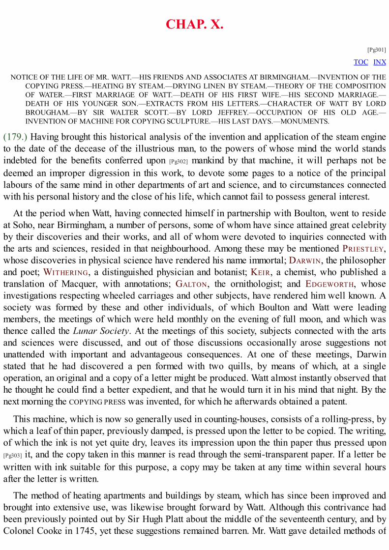
CHAP. X.
[Pg301]
TOC INX
NOTICE OF THE LIFE OF MR. WATT.—HIS FRIENDS AND ASSOCIATES AT BIRMINGHAM.—INVENTION OF THECOPYING PRESS.—HEATING BY STEAM.—DRYING LINEN BY STEAM.—THEORY OF THE COMPOSITIONOF WATER.—FIRST MARRIAGE OF WATT.—DEATH OF HIS FIRST WIFE.—HIS SECOND MARRIAGE.—DEATH OF HIS YOUNGER SON.—EXTRACTS FROM HIS LETTERS.—CHARACTER OF WATT BY LORDBROUGHAM.—BY SIR WALTER SCOTT.—BY LORD JEFFREY.—OCCUPATION OF HIS OLD AGE.—INVENTION OF MACHINE FOR COPYING SCULPTURE.—HIS LAST DAYS.—MONUMENTS.
(179.) Having brought this historical analysis of the invention and application of the steam engineto the date of the decease of the illustrious man, to the powers of whose mind the world standsindebted for the benefits conferred upon [Pg302] mankind by that machine, it will perhaps not bedeemed an improper digression in this work, to devote some pages to a notice of the principallabours of the same mind in other departments of art and science, and to circumstances connectedwith his personal history and the close of his life, which cannot fail to possess general interest.
At the period when Watt, having connected himself in partnership with Boulton, went to resideat Soho, near Birmingham, a number of persons, some of whom have since attained great celebrityby their discoveries and their works, and all of whom were devoted to inquiries connected withthe arts and sciences, resided in that neighbourhood. Among these may be mentioned PRIESTLEY,whose discoveries in physical science have rendered his name immortal; DARWIN, the philosopherand poet; WITHERING, a distinguished physician and botanist; KEIR, a chemist, who published atranslation of Macquer, with annotations; GALTON, the ornithologist; and EDGEWORTH, whoseinvestigations respecting wheeled carriages and other subjects, have rendered him well known. Asociety was formed by these and other individuals, of which Boulton and Watt were leadingmembers, the meetings of which were held monthly on the evening of full moon, and which wasthence called the Lunar Society. At the meetings of this society, subjects connected with the artsand sciences were discussed, and out of those discussions occasionally arose suggestions notunattended with important and advantageous consequences. At one of these meetings, Darwinstated that he had discovered a pen formed with two quills, by means of which, at a singleoperation, an original and a copy of a letter might be produced. Watt almost instantly observed thathe thought he could find a better expedient, and that he would turn it in his mind that night. By thenext morning the COPYING PRESS was invented, for which he afterwards obtained a patent.
This machine, which is now so generally used in counting-houses, consists of a rolling-press, bywhich a leaf of thin paper, previously damped, is pressed upon the letter to be copied. The writing,of which the ink is not yet quite dry, leaves its impression upon the thin paper thus pressed upon[Pg303] it, and the copy taken in this manner is read through the semi-transparent paper. If a letter bewritten with ink suitable for this purpose, a copy may be taken at any time within several hoursafter the letter is written.
The method of heating apartments and buildings by steam, which has since been improved andbrought into extensive use, was likewise brought forward by Watt. Although this contrivance hadbeen previously pointed out by Sir Hugh Platt about the middle of the seventeenth century, and byColonel Cooke in 1745, yet these suggestions remained barren. Mr. Watt gave detailed methods of

heating buildings by steam[25]; and also invented a machine for drying linen by steam, a descriptionof which he communicated to Dr. Brewster, which was read in December, 1824, before the Societyfor promoting Useful Arts in Scotland.[26]
But the circumstance, exclusive of those connected with the invention of the steam engine, whichis by far the most memorable in the career of Watt, is the share which he had in the discovery of thecomposition of water. As this circumstance has recently excited much interest, and led to somecontroversy, we shall here state, as distinctly as possible, the leading facts connected with it.
Water, which was so long held to be a simple element, has, in modern times, been proved to bea substance consisting of two aeriform bodies or gases chemically combined. These two gases arethose called in chemistry oxygen and hydrogen. If eight grains weight of oxygen be mixed with onegrain weight of hydrogen, and the mixture be submitted to such effects as would cause the chemicalcombination of these two airs, it would be converted into nine grains weight of pure water.
If, on the other hand, nine grains weight of pure water be submitted to any conditions whichwould separate its constituent parts, the result would be eight grains weight of oxygen gas, and onegrain weight of hydrogen gas. There are a variety of methods in physics by which these effectswould be [Pg304] produced. It will be sufficient here to state one method of producing each of theabove changes.
If eight grains weight of oxygen be inclosed in a strong vessel with one grain weight ofhydrogen, all other substances being excluded, and the mixture be inflamed, an explosion will takeplace, the gases will disappear, and a small quantity of water will be the only substance remainingin the vessel. If this water be weighed, it will be found to weigh exactly nine grains.
It is known that the metals have a strong attraction for oxygen gas, and this attraction is promotedby elevating their temperature. If a glass tube be filled with iron wire heated to redness, and to oneend of this tube a small vessel of boiling water be attached, the steam evolved from the water willforce its way through the spaces between the red-hot wires in the tube, and would be expected toissue from the remote end; but if the substance issuing from the remote end of the tube be examined,it will be found to be not steam, but hydrogen gas. If the quantity of this gas be ascertained byweight, and also the quantity of weight lost by the vessel of water at the other end of the tube, itwill be found that the loss of weight of the water by evaporation will be nine times the weight ofthe hydrogen which has issued from the remote end of the tube. If the weight of the tube with thewire contained in it be next ascertained, it will be found to be increased by eight times the weightof the hydrogen which has issued from its remote end. From this it follows that the weight of thehydrogen which has escaped from the tube, added to the increase of weight which has been givento the wire in the tube, makes up the whole weight of the water evaporated. If the wire in the tubebe next examined, it will be found that it has suffered oxydation, or, in other words, that a newsubstance has been formed in it called the oxyde of iron,—such substance being a chemicalcompound formed of oxygen gas and iron.
It follows, therefore, that in this process the vapour of the water, in passing through the tube, hasbeen decomposed, and that, having given up to the iron its oxygen, the hydrogen [Pg305] aloneescaped from the other end; and for every nine grains weight of steam which passed through thetube, eight grains of oxygen have been combined with the iron, and one grain of hydrogen hasescaped from the end of the tube.

Such are the class of effects on which the modern discovery of the composition of water hasbeen based. The merit of that discovery has been shared between the celebrated English chemist,CAVENDISH, and the not less celebrated French chemist, LAVOISIER, the chief merit, however, beingascribed to the former.
We shall now briefly state the facts which led to this discovery, with their dates, which willnecessarily show the share which Watt had in it.
When pure hydrogen gas is burned in an atmosphere of common air, the process which takesplace is now known to be nothing more than the chemical combination of the hydrogen with eighttimes its own weight of oxygen taken from the atmosphere, and the product of the combustion is aquantity of water nine times the weight of the hydrogen consumed. In the year 1776, Macquer, awell-known chemist of that day, having held a saucer of white porcelain over a flame of hydrogenwhich was burning at the mouth of a bottle, observed that no smoke was produced and no sootdeposited on the saucer. On the other hand, he found that after the lapse of some time drops of aclear pellucid liquid were perceptible on the saucer: this liquid he submitted to analysis, andfound it to be pure water. Macquer mentioned this fact without comment or inference. It did notoccur to him that the water thus produced upon the saucer was a substance which contained thehydrogen, which disappeared upon combustion from the bottle.
On the 18th of April, 1781, Mr. Warltire addressed a letter to Dr. Priestley, dated Birmingham,which letter is published in Dr. Priestley's Experiments on Air, printed at Birmingham in 1781, inwhich Warltire informs Priestley that he had fired a mixture of hydrogen and common air in closeglass vessels, and that, although previously to firing the mixture the vessels were clean and dry, adewy deposit was [Pg306] observed afterwards on their sides. In fact, water was present which wasnot present before.
The mixture was in this case fired by passing an electric spark through the vessel; and it is nowknown that the effect produced was the combination of the hydrogen, which formed part of themixture of airs in the vessel with the oxygen, which also formed part of the same mixture.
It appears, from expressions in Warltire's letter, that the same experiment had been previouslymade by Priestley, and the same result observed by him.
The inference deduced from this by Warltire, and apparently acquiesced in by Priestley, was,that whenever hydrogen was fired in atmospheric air, the moisture, which is always more or lesssustained in the latter, was deposited; but neither of these chemists perceived the real cause of theproduction of the water.
In the beginning of 1783, and not later than the 21st of April, this experiment of Warltire andPriestley was repeated by Cavendish, with this difference, that, instead of exploding the mixture ofhydrogen and common air, Cavendish exploded a mixture of hydrogen and oxygen. He observedthat water was present after the explosion, but inferred nothing.
In a published paper dated April, 1783, Priestley announced a further and most important resultof his experiments. This was, that in examining the weight of water produced by the explosion of amixture of oxygen and hydrogen, that weight was found to be precisely equal to the sum of theweights of the two gases, which disappeared in the process.
Immediately on observing this, Priestley, being then, as has been already stated, Watt's nearneighbour, communicated to the latter what he had observed; upon which Watt immediately, viz. by

a letter dated the 26th of the same month, declared that the inevitable consequence which followedfrom Priestley's observations was, that water was a substance compounded of oxygen andhydrogen deprived of [Pg307] a quantity of heat which was previously latent in them.[27] The lettercontaining this inference was communicated immediately by Priestley to Sir Joseph Banks, thenPresident of the Royal Society, to be laid before that body; and it is accordingly printed with itsproper date in the 74th volume of the Philosophical Transactions.
About two months after the date of Mr. Watt's letter just quoted, Lavoisier made experiments onthe combustion of oxygen and hydrogen, and read a memoir before the Academy of Sciences inParis, in which his views of the formation of water by the combination of these gases weredeveloped. This paper, by Lavoisier, was afterwards printed in the Memoirs of the Academy in theyear 1784. The experiments are there stated to have been made in the month of June, 1783; and it isstated that Sir Charles Blagden, who was present at the experiments, told Lavoisier that Mr.Cavendish had already burned the same gases in close vessels, and obtained a very sensiblequantity of water.
On the 15th of January, 1784, the celebrated paper by Cavendish, entitled "Experiments on Air,"was read before the Royal Society, and in this paper the composition of water by the union ofoxygen and hydrogen is explained.
In a controversy which afterwards ensued on the respective [Pg308] claims of Cavendish andLavoisier to credit for the discovery of the composition of water, Sir Charles Blagden stated thathe had told Lavoisier, in June, 1783, more than Lavoisier acknowledged, that he had not only toldhim that water was produced by the combustion of the gases, but that his information embraced thewhole theory of the composition of water. This declaration of Blagden was subsequent in date toJanuary, 1784, and there is no evidence of any explanation of this theory, verbal or otherwise,having been given by Cavendish, or any other person, antecedent to April, 1783.
From this brief statement of the facts and dates it will appear that the merit of the discovery ofthe FACT, that the weight of water resulting from the combustion of oxygen and hydrogen, is equalto the sum of the weights of the oxygen and hydrogen which disappear in the combustion, is due toPriestley; and that the merit of the INFERENCE from that fact, that water is a compound body, whoseconstituents are oxygen and hydrogen, is due to Watt.[28] Whether those who subsequently deducedthe same inference, and promulgated the same theory, were or were not informed of Mr. Watt'ssolution of the phenomenon, or what credit may be due to any person, however eminent, who at anytime posterior to Mr. Watt's letter to Priestley, asserted that they had, at a time antecedently to that,made the same inference without having published it, or communicated it in such a manner as toestablish their claim upon rational and credible evidence, are questions which we shall not herediscuss, being contented with establishing the right of Mr. Watt to the merit of the discovery of theTHEORY which explained the FACT discovered by Priestley.
Even in his declining years, after he had withdrawn from the active pursuits of his business, theleast excitement was sufficient to call into play the slumbering powers of his inventive genius. Noobject could present itself to his notice [Pg309] without receiving from that genius adaptation in formand construction to useful purposes. As an example of this restless activity of mind the followinganecdote may be mentioned:—
A company at Glasgow had erected on the right bank of the Clyde extensive buildings and
powerful engines for supplying water to the town. After this expense it was found that a source ofwater, of very superior quality, existed on the left bank of the river. To change the site of theestablishment, after the expense which had been incurred in its erection could not be contemplated,and they therefore proposed to carry across the bottom of the river a flexible suction pipe, themouth of which should terminate in the source from which the pure water was to be derived. Thispipe was to be supported by a flooring constructed upon the bed of the river; but it was soonapparent that the construction of such a flooring on a shifting and muddy bottom, full ofinequalities, and under several feet depth of water would require a greater expenditure of capitalthan could with propriety be afforded. In this difficulty the aged mechanician, for whom Glasgowitself had been the earliest stage of professional labour, was applied to, and instantly solved theproblem. His attention is said to have been attracted by a lobster which had been served at table:he set himself about to contrive how, by mechanism, he could make an apparatus of iron with jointswhich should have all the flexibility of the tail of the lobster. He therefore proposed that anarticulated suction-pipe, capable of accommodating itself to all the inequalities and to the possiblechanges of the bed of the river, should be carried across it; that this flexible pipe should be twofeet in diameter, and one thousand feet in length. This project the company accordingly caused tobe executed after the plans and drawings of Watt with the most complete success.[29]
[Pg310] Among the less prominent, though not less useful services rendered by Watt to his country,may be mentioned the introduction of the use of chlorine in bleaching. That invention of Bertholletwas introduced into England by Watt after his visit to Paris at the close of the year 1786. Heconstructed all the necessary apparatus for it, directed its erection, and superintended its firstperformances. He then left it to his wife's father, Mr. Macgregor, to carry on the processes.
When the properties of the gases began to occupy the attention of chemists, attempts were madeto apply them as a means of curing diseases of the lungs. Dr. Beddoes pursued this inquiry withgreat activity, and established, through the means of private subscription, at Clifton, an institutionin which this method of cure was carefully investigated. The Pneumatic Institution (for so it wascalled) has been rendered celebrated for having at its head Humphry Davy, just then commencinghis scientific career. Among its founders was also numbered James Watt. Not content, however,with affording the institution the sanction of his name, he designed and caused to be constructed, atSoho, the apparatus used for making the gases and administering them to the patients.
As the exalted powers of the mind of Watt, unfolded in his numerous mechanical andphilosophical inventions and discoveries, have commanded the admiration and respect of hisspecies, the affection and love of his fellow men would not have been less conciliated, had thequalities of his heart, as developed in his private and personal relations, been as well known asthe products of his genius.
In the year 1764, Watt being then in the twenty-ninth year of his age, married his cousin, MissMiller. At this time he had fallen into a state of despondency from his disappointments, whichproduced a serious attack of nervous illness. The accomplishments and superior understanding, themildness of temper and goodness of disposition of his wife, soon restored him to health. Of thismarriage four children, two sons and two daughters, were the issue. Two of these children died ininfancy; another, a daughter, was married to Mr. Miller of Glasgow; and the fourth is the [Pg311]
present Mr. James Watt. In September, 1773, while her husband was engaged in the design of theCaledonian canal in the North of Scotland, Mrs. Watt died in child-bed of a fifth child, who wasstill-born: "Would that I might here transcribe," says M. Arago, "in all their simple beauty, some
lines of the journal in which he daily recorded his inmost thoughts, his fears, his hopes! Would thatyou could see him, after this heavy affliction, pausing on the threshold of that home, where 'HIS
KIND WELCOMER' awaited him no more; unable to summon courage to enter those rooms where hewas never more to meet 'THE COMFORT OF HIS LIFE!' Possibly, so faithful a picture of a very deep sorrowmight at last put to silence those obstinate theorists, who, without being struck by the thousands ofinstances to the contrary, do yet refuse qualities of the heart to every man whose intellect has beenfostered by the fertile, sublime, and imperishable truths of the exact sciences!"
After the lapse of some years Watt married Miss Macgregor, a person who is represented tohave possessed qualities of mind which rendered her a companion every way suitable to herhusband. This lady survived Watt, and died in 1832 at an advanced age. Two children were theissue of this second marriage.
In the year 1800 the extended patent right, which had been granted to Boulton and Watt for theirimproved engine, expired, and at this time Mr. Watt retired altogether from business. He wassucceeded by his two sons, the present Mr. James Watt, and Gregory, one of the children of hissecond marriage. The works at Soho continued to be conducted by the present Mr. Boulton, the sonof the partner of Mr. Watt, and the two Messrs. Watt. In 1804 Gregory Watt died at the age oftwenty-seven, of a disease of the chest. This afflicting event was deeply felt by Mr. Watt; but hedid not sink under it into that state of despondency in which he has been represented to have fallenby M. Arago. On the contrary, he continued to show the same activity of mind which hadcharacterised his whole [Pg312] life; nor did he lose that interest which he always took in the pursuitof literature and in society. The state of his feelings under this affliction is shown by the followingextracts from letters written by him at that time, which have been published by Mr. Muirhead.

"Heathfield, January 26th, 1805.
* * "I, perhaps, have said too much to you and Mrs. Campbell on the state of my mind. I,therefore, think it necessary to say that I am not low spirited; and were you here, you wouldfind me as cheerful in the company of my friends as usual; my feelings for the loss of poorGregory are not passion, but a deep regret that such was his and my lot.
"I know that all men must die, and I submit to the decrees of nature, I hope with duereverence to the Disposer of Events. Yet one stimulus to exertion is taken away, and,somehow or other, I have lost my relish for my usual avocations. Perhaps time may remedythat in some measure; meanwhile, I do not neglect the means of amusement which are in mypower."
"Heathfield, April 8th, 1805.
* * "It is rather mortifying to see how easily the want of even the best of us is dispensedwith in the world; but it is very well it should be so. We here, however, cannot help feeling aterrible blank in our family. When I look at my son's books, his writings and drawings, Ialways say to myself, where are the mind that conceived these things, and the hands thatexecuted them? In the course of nature, he should have said so of mine; but it was otherwiseordered, and our sorrow is unavailing. As Catullus says:—
---- 'Nunc it, per iter tenebricosum,Illuc, unde negant redire quemquam.At vobis male sit, malæ tenebræOrci, quæ omnia bella devoratis!'
"But Catullus was a heathen; let us hope that he (G.) is now rejoicing in another and abetter world, free from our cares, griefs, and infirmities. Some one has said, I shall notwholly die; and Gregory's name, his merits and virtues, will live at least as long as those dowho knew him. You are not, from this, to conceive that we give way to grief; on the contrary,you will find us as cheerful as we ought to be, and as much disposed to enjoy the friends wehave left as ever; but we should approach to brutes if we had no regrets."
Mr. Watt, at the date of these letters, had entered on his seventieth year, a period after whichgreat mental exertions are rarely made. [Pg313]
In the summer of 1819, symptoms of indisposition manifested themselves which soon renderedWatt aware of his approaching dissolution. "I am very sensible," said he to his afflicted friends,"of the attachment you show me, and I hasten to thank you for it, as I am now come to my lastillness." He died on the 25th of August, 1819. His remains were deposited in the church ofHandsworth, near his estate of Heathfield. His son has raised over his grave a Gothic chapel, inthe centre of which is placed a statue by Chantrey.
The personal character of Watt could not fail to excite the admiration and the love of thosedistinguished persons, whose pride and happiness it was to be admitted to a share in the friendshipof the great engineer. Among these were reckoned some of the men who will leave upon thepresent age the deepest and most lasting impressions of their genius, and such persons havebequeathed to posterity the sentiments with which he inspired them. We cannot here do morejustice to the personal character of the subject of this notice than by repeating the portraiture of itwhich has been given by three of the most distinguished of his friends, and of the most illustrious

men of the present age.
At a meeting convened in 1824, for erecting a monument to Watt, Lord Brougham pronounced aspeech, from which we extract the following observations:—
"I had the happiness of knowing Mr. Watt, for many years, in the intercourse of private life;and I will take upon me to bear a testimony in which all who had that gratification I am surewill join, that they who only knew his public merit, prodigious as that was, knew but half hisworth. Those who were admitted to his society will readily allow that anything more pure,more candid, more simple, more scrupulously loving of justice, than the whole habits of hislife and conversation, proved him to be, was never known in society. One of the mostastonishing circumstances in this truly great man, was the versatility of his talents. Hisaccomplishments were so various, the powers of his mind were so vast, and yet of suchuniversal application, that it was hard to say whether we should most admire theextraordinary grasp of his understanding, or the accuracy of nice research with which hecould bring it to bear upon the most minute objects of investigation. I forget of whom it wassaid, that his mind resembled the trunk of an elephant, which can pick up [Pg314] straws, andtear up trees by the roots. Mr. Watt, in some sort, resembled the greatest and most celebratedof his own inventions, of which we are at a loss whether most to wonder at the power ofgrappling with the mightiest objects, or of handling the most minute; so that, while nothingseems too large for its grasp, nothing seems too small for the delicacy of its touch, which cancleave rocks, and pour forth rivers from the bowels of the earth, and, with perfect exactness,though not with greater ease, fashion the head of a pin, or strike the impress of some curiousdie. Now, those who knew Mr. Watt, had to contemplate a man whose genius could createsuch an engine, and indulge in the most abstruse speculations of philosophy, and could at oncepass from the most sublime researches of geology and physical astronomy, the formation ofour globe, and the structure of the universe, to the manufacture of a needle or a nail; whocould discuss, in the same conversation, and with equal accuracy, if not with the sameconsummate skill, the most forbidding details of art and the elegances of classical literature,the most abstruse branches of science and the niceties of verbal criticism.
"There was one quality in Mr. Watt which most honourably distinguished him from toomany inventors, and was worthy of all imitation—he was not only entirely free from jealousy,but he exercised a careful and scrupulous self-denial, and was anxious not to appear, even byaccident, as appropriating to himself that which he thought belonged to others. I have heardhim refuse the honour universally ascribed to him, of being the inventor of the steam engine,and call himself simply its improver; though, in my mind, to doubt his right to that honour,would be as inaccurate as to question Sir Isaac Newton's claim to his greatest discoveries,because Descartes in mathematics, and Galileo in astronomy and mechanics, had precededhim; or to deny the merits of his illustrious successor, because galvanism was not hisdiscovery, though, before his time, it had remained as useless to science as the instrumentcalled a steam engine was to the arts before Mr. Watt. The only jealousy I have known him tobetray, was with respect to others, in the nice adjustment he was fond of giving to the claimsof inventors. Justly prizing scientific discovery above all other possessions, he deemed thetitle to it so sacred, that you might hear him arguing by the hour to settle disputed rights; and ifyou ever perceived his temper ruffled, it was when one man's invention was claimed by, orgiven to another; or when a clumsy adulation pressed upon himself that which he knew to be

not his own."
In the preface to the Monastery Sir Walter Scott speaks of Watt in the following terms:—
"There were assembled about half a score of our northern lights. * * Amidst thiscompany stood Mr. Watt, the man whose genius discovered the means of multiplying ournational resources to a degree, perhaps, even beyond his own stupendous powers ofcalculation and combination; bringing the treasures of the abyss to the summit of the earth—giving the feeble arm of man the momentum of an Afrite—commanding manufactures to ariseas the rod of the prophet produced water in the desert—affording the means of dispensingwith that time and tide which wait for no man—and of sailing without that wind which defiedthe command and threats of Xerxes himself. This potent commander of the elements—thisabridger of time and space—this magician, whose cloudy [Pg315] machinery has produced achange on the world, the effects of which, extraordinary as they are, are, perhaps, only nowbeginning to be felt—was not only the most profound man of science—the most successfulcombiner of powers, and calculator of numbers, as adapted to practical purposes—was notonly one of the most generally well informed, but one of the best and kindest of human beings.
"There he stood, surrounded by the little band I have mentioned of northern literati, men notless tenacious, generally speaking, of their own fame and their own opinions, than the nationalregiments are supposed to be jealous of the high character which they have won upon service.Methinks I yet see and hear what I shall never see or hear again. In his eighty-second year, thealert, kind, benevolent old man, had his attention alive to every one's question, hisinformation at every one's command.
"His talents and fancy overflowed on every subject. One gentleman was a deep philologist—he talked with him on the origin of the alphabet, as if he had been coeval with Cadmus;another a celebrated critic—you would have said the old man had studied political economyand belles lettres all his life. Of science it is unnecessary to speak—it was his owndistinguished walk. And yet, Captain Clutterbuck, when he spoke with your countryman,Jedediah Cleishbotham, you would have sworn he had been coeval with Claverse and Burley,with the persecutors and persecuted, and could number every shot the dragoons had fired atthe fugitive Covenanters. In fact, we discovered that no novel of the least celebrity escapedhis perusal, and that the gifted man of science was as much addicted to the productions ofyour native country, in other words, as shameless and obstinate a peruser of novels, as if hehad been a very milliner's apprentice of eighteen."
In the Edinburgh newspaper, called the Scotsman, of the 4th September, 1819, immediately afterthe decease of Watt, the following sketch was published from the pen of Lord Jeffrey:—
"This name fortunately needs no commemoration of ours; for he that bore it survived to seeit crowned with undisputed and unenvied honours; and many generations will probably passaway before it shall have gathered 'all its fame.' We have said that Mr. Watt was the greatimprover of the steam engine; but, in truth, as to all that is admirable in its structure, or vast inits utility, he should rather be described as its inventor. It was by his inventions, that itsaction was so regulated as to make it capable of being applied to the finest and most delicatemanufactures, and its power so increased, as to set weight and solidity at defiance. By hisadmirable contrivance, it has become a thing stupendous alike for its force and its flexibility—for the prodigious power which it can exert, and the ease, and precision, and ductility with

which it can be varied, distributed, and applied. The trunk of an elephant, that can pick up apin or rend an oak, is as nothing to it. It can engrave a seal, and crush masses of obduratemetal before it—draw out, without breaking, a thread as fine as gossamer, and lift a ship ofwar like a bauble in the air. It can embroider muslin, and forge anchors—cut steel intoribands, and impel loaded vessels against the fury of the winds and waves. [Pg316]
"It would be difficult to estimate the value of the benefits which these inventions haveconferred upon this country. There is no branch of industry that has not been indebted to them;and, in all the most material, they have not only widened most magnificently the field of itsexertions, but multiplied a thousand fold the amount of its productions. It is our improvedsteam engine that has fought the battles of Europe, and exalted and sustained, through the latetremendous contest, the political greatness of our land. It is the same great power which nowenables us to pay the interest of our debt, and to maintain the arduous struggle in which weare still engaged (1819), with the skill and capital of countries less oppressed with taxation.But these are poor and narrow views of its importance. It has increased indefinitely the massof human comforts and enjoyments, and rendered cheap and accessible all over the world thematerials of wealth and prosperity. It has armed the feeble hand of man, in short, with apower to which no limits can be assigned; completed the dominion of mind over the mostrefractory qualities of matter; and laid a sure foundation for all those future miracles ofmechanic power which are to aid and reward the labours of after generations. It is to thegenius of one man, too, that all this is mainly owing; and certainly no man ever bestowed sucha gift on his kind. The blessing is not only universal, but unbounded; and the fabled inventorsof the plough and the loom, who were deified by the erring gratitude of their rudecontemporaries, conferred less important benefits on mankind than the inventor of our presentsteam engine.
"This will be the fame of Watt with future generations; and it is sufficient for his race andhis country. But to those to whom he more immediately belonged, who lived in his society andenjoyed his conversation, it is not, perhaps, the character in which he will be most frequentlyrecalled—most deeply lamented—or even most highly admired. Independently of his greatattainments in mechanics, Mr. Watt was an extraordinary, and in many respects a wonderfulman. Perhaps no individual in his age possessed so much and such varied and exactinformation—had read so much, or remembered what he had read so accurately and well. Hehad infinite quickness of apprehension, a prodigious memory, and a certain rectifying andmethodising power of understanding, which extracted something precious out of all that waspresented to it. His stores of miscellaneous knowledge were immense; and yet lessastonishing than the command he had at all times over them. It seemed as if every subject thatwas casually started in conversation with him, had been that which he had been last occupiedin studying and exhausting;—such was the copiousness, the precision, and the admirableclearness of the information which he poured out upon it without effort or hesitation. Nor wasthis promptitude and compass of knowledge confined in any degree to the studies connectedwith his ordinary pursuits. That he should have been minutely and extensively skilled inchemistry and the arts, and in most of the branches of physical science, might perhaps havebeen conjectured; but it could not have been inferred from his usual occupations, andprobably is not generally known, that he was curiously learned in many branches of antiquity,metaphysics, medicine, and etymology; and perfectly at home in all the details of architecture,music, and law. He was well acquainted, too, with most of the modern languages, and
familiar with their most recent literature. Nor was it at all extraordinary to hear the greatmechanician and engineer detailing and expounding, for hours together, [Pg317] the metaphysicaltheories of the German logicians, or criticising the measures or the matter of the Germanpoetry.
"His astonishing memory was aided, no doubt, in a great measure, by a still higher andrarer faculty—by his power of digesting, and arranging in its proper place, all the informationhe received; and of casting aside and rejecting, as it were instinctively, whatever wasworthless or immaterial. Every conception that was suggested to his mind seemed instantly totake its place among its other rich furniture, and to be condensed into the smallest and mostconvenient form. He never appeared, therefore, to be at all incumbered or perplexed with theverbiage of the dull books he perused, or to the idle talk to which he listened; but to have atonce extracted, by a kind of intellectual alchemy, all that was worthy of attention, and to havereduced it, for his own use, to its true value and to its simplest form. And thus it oftenhappened, that a great deal more was learned from his brief and vigorous account of thetheories and arguments of tedious writers, than an ordinary student could ever have derivedfrom the most painful study of the originals; and that errors and absurdities became manifestfrom the mere clearness and plainness of his statement of them, which might have deluded andperplexed most of his hearers without that invaluable assistance.
"It is needless to say that, with those vast resources, his conversation was at all times richand instructive in no ordinary degree: but it was, if possible, still more pleasing than wise;and had all the charms of familiarity with all the substantial treasures of knowledge. No mancould be more social in his spirit, less assuming or fastidious in his manners, or more kindand indulgent toward all who approached him. He rather liked to talk,—at least in his latteryears; but though he took a considerable share of the conversation, he rarely suggested thetopics on which it was to turn, but readily and quietly took up whatever was presented bythose around him, and astonished the idle and barren propounders of an ordinary theme by thetreasures which he drew from the mine they had unconsciously opened. He generally seemed,indeed, to have no choice or predilection for one subject of discourse rather than another; butallowed his mind, like a great cyclopædia, to be opened at any letter his associates mightchoose to turn up, and only endeavoured to select from his inexhaustible stores, what might bebest adapted to the taste of his present hearers. As to their capacity he gave himself notrouble; and indeed such was his singular talent for making all things plain, clear, andintelligible, that scarcely any one could be aware of such a deficiency in his presence. Histalk, too, though overflowing with information, had no resemblance to lecturing or solemndiscoursing, but, on the contrary, was full of colloquial spirit and pleasantry. He had a certainquiet and grave humour which ran through most of his conversation; and a vein of temperatejocularity, which gave infinite zest and effect to the condensed and inexhaustible informationwhich formed its main staple and characteristic. There was a little air of affected testiness,and a tone of pretended rebuke and contradiction, with which he used to address his youngerfriends, that was always felt by them as an endearing mark of his kindness and familiarity; andprized, accordingly, far beyond all the solemn compliments that ever proceeded from the lipsof authority. His voice was deep and powerful, though he commonly spoke in a low andsomewhat monotonous tone, which harmonised admirably with the weight and brevity of hisobservations, and set off to the greatest advantage the pleasant [Pg318] anecdotes, which hedelivered with the same grave brow, and the same calm smile playing soberly on his lips.

There was nothing of effort, indeed, or impatience, any more than of pride or levity, in hisdemeanour; and there was a finer expression of reposing strength, and mild self-possession inhis manner, than we ever recollect to have met with in any other person. He had in hischaracter the utmost abhorrence for all sorts of forwardness, parade, and pretensions; and,indeed, never failed to put all such impostures out of countenance, by the manly plainness andhonest intrepidity of his language and deportment.
"In his temper and dispositions, he was not only kind and affectionate, but generous, andconsiderate of the feelings of all around him; and gave the most liberal assistance andencouragement to all young persons who showed any indications of talent, or applied to himfor patronage or advice. His health, which was delicate from his youth upwards, seemed tobecome firmer as he advanced in years; and he preserved, up almost to the last moment of hisexistence, not only the full command of his extraordinary intellect, but all the alacrity of spiritand the social gaiety which had illumined his happiest days. His friends in this part of thecountry never saw him more full of intellectual vigour and colloquial animation—never moredelightful or more instructive—than in his last visit to Scotland in autumn 1817. Indeed, itwas after that time that he applied himself, with all the ardour of early life, to the invention ofa machine for mechanically copying all sorts of sculpture and statuary; and distributed amonghis friends some of its earliest performances, as the productions of a young artist just enteringon his eighty-third year.
"This happy and useful life came, at last, to a gentle close. He had suffered someinconvenience through the summer; but was not seriously indisposed till within a few weeksof his death. He then became perfectly aware of the event which was approaching; and withhis usual tranquillity and benevolence of nature, seemed only anxious to point out to thefriends around him, the many sources of consolation which were afforded by thecircumstances under which it was about to take place. He expressed his sincere gratitude toProvidence for the length of days with which he had been blessed, and his exemption frommost of the infirmities of age; as well as for the calm and cheerful evening of life that he hadbeen permitted to enjoy, after the honourable labours of the day had been concluded. Andthus, full of years and honours, in all calmness and tranquillity, he yielded up his soul withoutpang or struggle; and passed from the bosom of his family to that of his God."
The English nation has ever shown itself insensible to the claims of genius and high intellectualendowments, except where the results have been brought directly to bear in statesmanship or war.Of this inability to appreciate the highest order of intellectual excellence Watt affords a strikingexample. When it was suggested to the British government by those better capable than thatgovernment was of appreciating the genius of this great man, that the nation would do itself honourby erecting a splendid monument at his own [Pg319] cost to him to whom it was so deeply indebtedfor the extension of its resources and the augmentation of its power, the reply was that such ameasure could not be adopted as it might be drawn into a precedent in like cases thereafter! Aprecedent in like cases!! When will the time arrive when the world will produce a like case? Themonument which has been erected in Westminster Abbey was in fact raised by privatesubscription, the nation having thus stigmatised itself through the act of its government with theeverlasting disgrace of refusing the honour proposed to it. The other statues and monuments whichhave been erected to this great man, have been for the most part raised by the filial piety and thenever-dying affection and veneration of the present Mr. James Watt. A statue has been presented by

him to the University of Glasgow, and placed in one of the halls of that college. The inhabitants ofGreenock have also erected a marble statue of Watt, for which, and for a library, a building hasbeen erected at the expense of about 3,500l. which has been defrayed by Mr. James Watt. Acolossal bronze statue has been erected on a handsome granite pedestal, standing at one of thecorners of George Square, Glasgow. The monument in Westminster Abbey, erected by thesubscription raised at the public meeting already alluded to, is a colossal statue of Carrara marble,by Chantrey.
Watt was elected a fellow of the Royal Society of Edinburgh in 1784; of the Royal Society ofLondon in 1785; a member of the Batavian Society in 1787; and a corresponding member of theInstitut of France in 1808. The degree of Doctor of Laws was conferred upon him by the Universityof Glasgow, in 1806; and in 1814, the highest scientific honour which can be attained by aphilosopher, was conferred on him by the Academy of Sciences of the Institut of France, whonominated him one of its eight foreign associates.
On the pedestal of the monument in Westminster Abbey is engraved the following inscriptionfrom the pen of Lord Brougham:— [Pg320]

NOT TO PERPETUATE A NAMEWHICH MUST ENDURE WHILE THE PEACEFUL ARTS FLOURISH,
BUT TO SHOWTHAT MANKIND HAVE LEARNED TO HONOUR THOSE
WHO BEST DESERVE THEIR GRATITUDE,THE KING
HIS MINISTERS, AND MANY OF THE NOBLESAND COMMONERS OF THE REALM
RAISED THIS MONUMENT TOJAMES WATT,
WHO DIRECTING THE FORCE OF AN ORIGINAL GENIUS,EARLY EXERCISED IN PHILOSOPHIC RESEARCH
TO THE IMPROVEMENT OFTHE STEAM ENGINE,
ENLARGED THE RESOURCES OF HIS COUNTRY,INCREASED THE POWER OF MAN,
AND ROSE TO AN EMINENT PLACEAMONG THE MOST ILLUSTRIOUS FOLLOWERS OF SCIENCE
AND THE REAL BENEFACTORS OF THE WORLD.BORN AT GREENOCK MDCCXXXVI.
DIED AT HEATHFIELD IN STAFFORDSHIRE MDCCCXIX.
WATT'S CHAPEL IN HANDSWORTH CHURCH.

FOOTNOTES:[25] See Buchanan on the Economy of Fuel and Management of Heat, especially as it relates to heating and drying by
means of Steam.
[26] See Brewster's Edinburgh Encyclopædia, article ST EAM-DRYING MACHINE.
[27] The following are the words in which Watt makes this remarkable announcement to Priestley:—
"Let us now consider what obviously happens in the deflagration of the inflammable (hydrogen) and dephlogisticated air(oxygen). These two kinds of air unite with violence; they become red hot, and upon cooling, totally disappear. Whenthe vessel is cooled, a quantity of water is found in it equal to the weight of the air employed. This water is then theonly remaining product of the process; and water, light, and heat are all the products.
"Are we not then authorised to conclude, that water is composed of dephlogisticated air (oxygen) and phlogiston(hydrogen), deprived of part of their latent or elementary heat; that dephlogisticated or pure air (oxygen) is composedof water deprived of its phlogiston (hydrogen), and united to elementary heat and light; and that the latter arecontained in it in a latent state, so as not to be sensible to the thermometer or to the eye; and if light be only amodification of heat, or a circumstance attending it, or a component part of the inflammable air (hydrogen), then pureor dephlogisticated air (oxygen) is composed of water deprived of its phlogiston (hydrogen), and united to elementaryheat."
[28] Those who desire to investigate this controversy more in detail will find very full information on the subject in theTranslation of Arago's Eloge, with notes and appendix by J. P. Muirhead, Esq. Murray, London, 1839.
[29] An account of this remarkable apparatus, accompanied by an engraving made from a drawing supplied by Watt, wascommunicated by Sir John Robison to the Edinburgh Philosophical Journal in 1820. See vol. iii, p. 60.

CHAP. XI.
LOCOMOTIVE ENGINES ON RAILWAYS.[Pg321]
TOC INX
NON-CONDENSING ENGINES.—LEUPOLD'S ENGINE.-TREVETHICK AND VIVIAN.—EFFECTS OF RAILWAYTRANSPORT.—HISTORY OF THE LOCOMOTIVE ENGINE.—BLENKINSOP.—MESSRS. CHAPMAN.—WALKING ENGINE.—MR. STEPHENSON'S ENGINES AT KILLINGWORTH.—LIVERPOOL ANDMANCHESTER RAILWAY.—EXPERIMENTAL TRIAL.—THE ROCKET.—THE SANSPAREIL.—THE NOVELTY.—SUBSEQUENT IMPROVEMENTS IN THE LOCOMOTIVE ENGINE.—LARDNER'S EXPERIMENTS IN 1832.—ADOPTION OF BRASS TUBES.—MR. BOOTH'S REPORT.—DETAILED DESCRIPTION OF THE MOSTIMPROVED LOCOMOTIVE ENGINES.—POWER OF LOCOMOTIVE ENGINES.—EVAPORATION OF BOILERS.—LARDNER'S EXPERIMENTS IN 1838.—RESISTANCE TO RAILWAY TRAINS.—RESTRICTIONS ONGRADIENTS.—COMPENSATING EFFECT OF GRADIENTS.—EXPERIMENT WITH THE HECLA.—METHODSOF SURMOUNTING STEEP INCLINATIONS.
(180.) In the various modifications of the steam engine which we have hitherto considered, thepressure introduced on one side of the piston derives its efficacy either wholly or partially fromthe vacuum produced by condensation on the other side. This always requires a condensingapparatus, and a constant and abundant supply of cold water. An engine of this kind must thereforenecessarily have considerable dimensions and weight, and is inapplicable to uses in which a smalland light machine only is admissible. If the condensing apparatus be dispensed with, the pistonwill always be resisted by a force equal to the atmospheric [Pg322] pressure, and the only part of thesteam pressure which will be available as a moving power, is that part by which it exceeds thepressure of the atmosphere. Hence, in engines which do not work by condensation, steam of amuch higher pressure than that of the atmosphere is indispensably necessary, and such engines aretherefore called high-pressure engines.
We are not, however, to understand that every engine, in which steam is used of a pressureexceeding that of the atmosphere, is what is meant by an high-pressure engine; for in the ordinaryengines in common use, constructed on Watt's principle, the safety-valve is loaded with from 3 to 5lbs. on the square inch; and in Woolf's engines, the steam is produced under a pressure of 40 lbs.on the square inch. These would therefore be more properly called condensing engines than low-pressure engines; a term quite inapplicable to those of Woolf. In fact, by high-pressure engines ismeant engines in which no vacuum is produced, and, therefore, in which the piston works against apressure equal to that of the atmosphere.
In these engines the whole of the condensing apparatus, viz. the cold-water cistern, condenser,air-pump, cold-water pump, &c., are dispensed with, and nothing is retained except the boiler,cylinder, piston, and valves. Consequently, such an engine is small, light, and cheap. It is portablealso, and may be moved, if necessary, along with its load, and is therefore well adapted tolocomotive purposes.
(181.) High-pressure engines were one of the earliest forms of the steam engine. Thecontrivance, which is obscurely described in the article already quoted (7.), from the Century ofInventions, is a high-pressure engine; for the power there alluded to is the elastic force of steamworking against the atmospheric pressure. Newcomen, in 1705, applied the working-beam,cylinder, and piston to the atmospheric engine; and Leupold, about 1720, combined the working-

beam and cylinder with the high-pressure principle, and produced the earliest high-pressure engineworked by a cylinder and piston. The following is a description of Leupold's engine:— [Pg323]
Fig. 82.
A (fig. 82.) is the boiler, with the furnace beneath it; C C are two cylinders with solid pistons P P
′, connected with the working-beams B B′, to which are attached the pump-rods R R′, of two forcingpumps F F′, which communicate with a great force-pipe S; G is a four-way cock (66.) alreadydescribed. In the position in which it stands in the figure, the steam issues from below the piston Pinto the atmosphere, and the piston is descending by its own weight; steam from the boiler is at thesame time pressing up the piston P′, with a force equal to the difference between the pressure of thesteam and that of the atmosphere. Thus the piston R of the forcing-pump is being drawn up, and thepiston P′ is forcing the piston R′ down, and thereby driving water into the force-pipe [Pg324] S. On thearrival of the piston P at the bottom of the cylinder C, and P′ at the top of the cylinder C′, theposition of the cock is changed as represented in fig. 83. The steam, which has just pressed up thepiston P′, is allowed to escape into the atmosphere, while the steam, passing from the boiler belowthe piston P, presses it up, and thus P ascends by the steam pressure, and P′ descends by its ownweight. By these means the piston R is forced down, driving before it the water in the pump-cylinder into the force-pipe S, and the piston R′ is drawn up to allow the other pump-cylinder to bere-filled; and so the process is continued.

Fig. 83.
A valve is placed in the bottom of the force-pipes, to prevent the water which has been driveninto it from returning. This valve opens upwards; and, consequently, the weight of the waterpressing upon it only keeps it more effectually closed. On each descent of the piston, the pressuretransmitted to the valve acting upwards being greater than the weight of the water resting upon it,forces it open, and an increased quantity of water is introduced.
(182.) From the date of the improvement of Watt until the commencement of the present century,non-condensing engines were altogether neglected in these countries. In the year 1802, Messrs.Trevethick and Vivian constructed the first non-condensing engine of this kind which was everbrought into extensive practical use in this kingdom. A section of this machine, made by a verticalplane, is represented in fig. 84.
The boiler A B is a cylinder with flat circular ends. The fire-place is constructed in thefollowing manner:—A tube enters the cylindrical boiler at one end; and, proceeding onwards nearthe other extremity, is turned and recurved, so as to be carried back parallel to the direction inwhich it entered. It is thus conducted out of the boiler, at another part of the same end at which itentered. One of the ends of this tube communicates with the chimney E, which is carried upwardsas represented in the figure. The other mouth is furnished [Pg325] with a door; and in it is placed thegrate, which is formed of horizontal bars, dividing the tube into two parts; the upper part formingthe fire-place, and the lower the ash-pit. The fuel is maintained in a state of combustion, on thebars, in that part of the tube represented at C D; and the flame is carried by the draught of thechimney round the curved flue, and issues at E into the chimney. The flame is thus conductedthrough the water, so as to expose the latter to as much heat as possible.

Fig. 84.
A section of the cylinder is represented at F, immersed in the boiler, except a few inches of theupper end, where the four-way cock G is placed for regulating the admission of the steam. A tube isrepresented at H, which leads from this four-way cock into the chimney; so that the waste steam,after working the piston, is carried off through this tube, and passes into the chimney. The upperend of the piston-rod is furnished with a cross-bar, which is placed in a direction at right angles tothe length of the boiler, and also to the [Pg326] piston-rod. This bar is guided in its motion by slidingon two iron perpendicular rods fixed to the sides of the boiler, and parallel to each other. To theends of this cross-bar are joined two connecting rods, the lower ends of which work two cranksfixed on an axis extending across and beneath the boiler, and immediately under the centre of thecylinder. This axis is sustained in bearings formed in the legs which support the boiler, and uponits extremity is fixed the fly-wheel as represented at B. A large-toothed wheel is placed on thisaxis; which, being turned with the cranked axle, communicates motion to other wheels; and throughthem, to any machinery which the engine may be applied to move.
Fig. 85.
As the four-way cock is represented in the figure, the steam passes from the boiler through thecurved passage G above the piston, while the steam below the piston is carried off through a tubewhich does not appear in the figure, by which it is conducted to the tube H, and thence to the

chimney. The steam, therefore, which passes above the piston presses it downwards; while thepressure upwards does not exceed that of the atmosphere. The piston will therefore descend with aforce depending on the excess of the pressure of the steam produced in the boiler above theatmospheric pressure. When the piston has arrived at the bottom of the cylinder, the cock is madeto assume the position represented in fig. 85. This effect is produced by the motion of the piston-rod. The steam now passes from above the piston, through the tube H, into the chimney, while thesteam from the boiler is conducted through another tube below the piston. The pressure above thepiston, in this case, does not exceed that of the atmosphere; while the pressure below it will be thatof the steam in the boiler. The piston will therefore ascend with the difference of these pressures.On the arrival of the piston at the top of the cylinder, the four-way cock is again turned to theposition represented in fig. 85., and the piston again descends; and in the same manner the processis continued. A safety-valve is placed on the boiler at V, loaded with a weight W, proportionate[Pg327] to the strength of the steam with which it is proposed to work.
In the engines now described, this valve was frequently loaded at the rate of from 60 to 80 lbs.on the square inch. As the boilers of high-pressure engines were considered more liable toaccidents from bursting than those in which steam of a lower pressure was used, greaterprecautions were taken against such effects. A second safety-valve was provided, which was notleft in the power of the engine-man. By this means he had a power to diminish the pressure of thesteam, but could not increase it beyond the limit determined by the valve which was removed fromhis interference. The greatest cause of danger, however, arose from the water in the boiler beingconsumed by evaporation faster than it was supplied; and therefore falling below the level of thetube containing the furnace. To guard against accidents arising from this circumstance, a hole wasbored in the boiler, at a certain depth, below which the water should not be allowed to fall; and inthis hole a plug of metal was soldered with lead, or with some other metal, which would fuse atthat temperature which would expose the boiler to danger. Thus, in the event of the water beingexhausted, so that its level would fall below the plug, the heat of the furnace would immediatelymelt the solder, and the plug would fall out, affording a vent for the steam, without allowing theboiler to burst. The mercurial steam-gauge, already described, was also used as an additionalsecurity. When the force of the steam exceeded the length of the column of mercury which the tubewould contain, the mercury would be blown out, and the tube would give vent to the steam. Thewater by which the boiler was replenished was forced into it by a pump worked by the engine. Inorder to economise the heat, this water was contained in a tube T, which surrounded the pipe H. Asthe waste steam, after working the piston, passed off through H, it imparted a portion of its heat tothe water contained in the tube T, which was thus warmed to a certain temperature before it wasforced into the boiler by the pump. Thus a part of the heat, which was originally [Pg328] carried fromthe boiler in the form of steam, was returned again to the boiler with the water with which it wasfed.
It is evident that engines constructed in this manner may be applied to all the purposes to whichthe condensing engines are applicable.
(183.) Two years after the date of the patent of this engine, its inventor constructed a machine ofthe same kind for the purpose of moving carriages on railroads; and applied it successfully, in theyear 1804, on the railroad at Merthyr Tydvil, in South Wales. It was in principle the same as thatalready described. The cylinder however was in a horizontal position, the piston-rod working inthe direction of the line of road: the extremity of the piston-rod, by means of a connecting rod,

worked cranks placed on the axletree, on which were fixed two cogged wheels: these worked inothers, by which their motion was communicated finally to cogged wheels fixed on the axle of thehind wheels of the carriage, by which this axle was kept in a state of revolution. The hind wheelsbeing fixed on the axletree, and turning with it, were caused likewise to revolve; and so long as theweight of the carriage did not exceed that which the friction of the road was capable of propelling,the carriage would thus be moved forwards. On this axle was placed a fly-wheel to continue therotatory motion at the termination of each stroke. The fore wheels are described as being capableof turning like the fore wheels of a carriage, so as to guide the vehicle. The projectors appear tohave contemplated, in the first instance, the use of this carriage on common roads; but that notionseems to have been abandoned, and its use was only adopted on the railroad before mentioned. Onthe occasion of its first trial, it drew after it as many carriages as contained ten tons of iron adistance of nine miles; which stage it performed without any fresh supply of water, and travelled atthe rate of five miles an hour.
(184.) Capital and skill have of late years been directed with extraordinary energy to theimprovement of inland transport; and this important instrument of national wealth and civilisationhas received a proportionate impulse. Effects are now witnessed, which, had they been narrated afew years [Pg329] since, could only have been admitted into the pages of fiction or volumes ofromance. Who could have credited the possibility of a ponderous engine of iron, loaded with somehundred passengers, in a train of carriages of corresponding magnitude, and a large quantity ofwater and coal, taking flight from Manchester and arriving at Liverpool, a distance of above thirtymiles, in little more than an hour? And yet this is a matter of daily and almost hourly occurrence.The rapidity of transport thus attained is not less wonderful than the weights transported. Itscapabilities in this respect far transcend the exigencies even of the two greatest commercial martsin Great Britain. Loads, varying from fifty to one hundred and fifty tons, are transported at theaverage rate of fifteen miles an hour; and in one instance we have seen a load—we should rathersay a cargo—of waggons, conveying merchandise to the amount of two hundred and thirty tonsgross, transported from Liverpool to Manchester at the average rate of twelve miles an hour.
The astonishment with which such performances must be viewed, might be qualified, if the art oftransport by steam on railways had been matured, and had attained that full state of perfectionwhich such an art is always capable of receiving from long experience, aided by great scientificknowledge, and the unbounded application of capital. But such is not the present case. The art ofconstructing locomotive engines, so far from having attained a state of maturity, has not evenemerged from its infancy. So complete was the ignorance of its powers which prevailed, evenamong engineers, previous to the opening of the Liverpool railway, that the transport of heavygoods was regarded as the chief object of the undertaking, and its principal source of revenue. Theincredible speed of transport, effected even in the very first experiments in 1830, burst upon thepublic, and on the scientific world, with all the effect of a new and unlooked-for phenomenon. Onthe unfortunate occasion which deprived this country of Mr. Huskisson, the wounded body of thatstatesman was transported a distance of about fifteen miles in twenty-five minutes, being at the rateof thirty-six miles an hour. The revenue of the road arising from passengers since its opening, [Pg330]
has, contrary to all that was foreseen, been nearly double that which has been derived frommerchandise. So great was the want of experience in the construction of engines, that the companywas at first ignorant whether they should adopt large steam engines fixed at different stations on theline, to pull the carriages from station to station, or travelling engines to drag the loads the entiredistance. Having decided on the latter, they have, even to the present moment, laboured under the

disadvantage of the want of that knowledge which experience alone can give. The engines havebeen constantly varied in their weight and proportions, in their magnitude and form, as theexperience of each successive month has indicated. As defects became manifest they wereremedied; improvements suggested were adopted; and each year produced engines of suchincreased power and efficiency, that their predecessors were abandoned, not because they wereworn out, but because they had been outstripped in the rapid march of improvement. Add to this,that only one species of travelling engine has been effectively tried; the capabilities of othersremain still to be developed; and even that form of engine which has received the advantage of acourse of experiments on so grand a scale to carry it towards perfection, is far short of this point,and still has defects, many of which, it is obvious, time and experience will remove.
If, then, the locomotive engine, subject thus to all the imperfections inseparable from a novelcontrivance—with the restrictions on the free application of skill and capital, arising from thenature of the monopolies granted to railway companies—with the disadvantage of very limitedexperience, the great parent of practical improvement, having been submitted to experimentshitherto only on a limited scale, and confined almost to one form of machine;—if, under suchdisadvantages, such effects have been produced as are now daily witnessed by the public, whatmay not be looked for from this extraordinary power when the enterprise of the country shall bemore unfettered—when greater fields of experience are opened—when time, ingenuity, and capitalhave removed or diminished existing imperfections, and have brought to light new and morepowerful principles? This is not mere speculation [Pg331] on abstract possibilities, but refers to whatis in actual progress. The points of greatest wealth and population—the centres of largest capitaland most active industry throughout the country—will soon be connected by lines of railway; andvarious experiments are proposed, with more or less prospect of success, for the application ofsteam engines on stone roads where the intercourse is not sufficient to render railways profitable.
The important commercial and political effects attending such increased facility and speed in thetransport of persons and goods, are too obvious to require any very extended notice here. A part ofthe price (and in many cases a considerable part) of every article of necessity or luxury, consists ofthe cost of transporting it from the producer to the consumer; and consequently every abatement orsaving in this cost must produce a corresponding reduction in the price of every articletransported; that is to say, of every thing which is necessary for the subsistence of the poor, or forthe enjoyment of the rich—of every comfort, and of every luxury of life. The benefit of this willextend, not to the consumer only, but to the producer: by lowering the expense of transport of theproduce, whether of the soil or of the loom, a less quantity of that produce will be spent in bringingthe remainder to market, and consequently a greater surplus will reward the labour of the producer.The benefit of this will be felt even more by the agriculturist than by the manufacturer; because theproportional cost of transport of the produce of the soil is greater than that of manufactures. If twohundred quarters of corn be necessary to raise four hundred, and one hundred more be required tobring the four hundred to market, then the net surplus will be one hundred. But if by the use ofsteam carriages the same quantity can be brought to market with an expenditure of fifty quarters,then the net surplus will be increased from one hundred to one hundred and fifty quarters; andeither the profit of the farmer, or the rent of the landlord, must be increased by the same amount.
But the agriculturist would not merely be benefited by an increased return from the soil alreadyunder cultivation. Any [Pg332] reduction in the cost of transporting the produce to market would callinto cultivation tracts of inferior fertility, the returns from which would not at present repay the

cost of cultivation and transport. Thus land would become productive which is now waste, and aneffect would be produced equivalent to adding so much fertile soil to the present extent of thecountry. It is well known, that land of a given degree of fertility will yield increased produce bythe increased application of capital and labour. By a reduction in the cost of transport, a savingwill be made which may enable the agriculturist to apply to tracts already under cultivation thecapital thus saved, and thereby increase their actual production. Not only, therefore, would such aneffect be attended with an increased extent of cultivated land, but also with an increased degree ofcultivation in that which is already productive.
It has been said, that in Great Britain there are above a million of horses engaged in variousways in the transport of passengers and goods, and that to transport each horse requires as muchland as would, upon an average, support eight men. If this quantity of animal power weredisplaced by steam engines, and the means of transport drawn from the bowels of the earth, insteadof being raised upon its surface, then, supposing the above calculation correct, as much land wouldbecome available for the support of human beings as would suffice for an additional population ofeight millions; or, what amounts to the same, would increase the means of support of the presentpopulation by about one third of the present available means. The land which now supports horsesfor transport would then support men, or produce corn for food.
The objection that a quantity of land exists in the country capable of supporting horses alone,and that such land would be thrown out of cultivation, scarcely deserves notice here. The existenceof any considerable quantity of such land is extremely doubtful. What is the soil which will feed ahorse and not feed oxen or sheep, or produce food for man? But even if it be admitted that thereexists in the country a small portion of such land, that portion cannot exceed, nor indeed equal,what would be sufficient for the number of horses [Pg333] which must after all continue to beemployed for the purposes of pleasure, and in a variety of cases where steam must necessarily beinapplicable. It is to be remembered, also, that the displacing of horses in one extensiveoccupation, by diminishing their price must necessarily increase the demand for them in others.
The reduction in the cost of transport of manufactured articles, by lowering their price in themarket, will stimulate their consumption. This observation applies of course not only to home butto foreign markets. In the latter we already in many branches of manufactures command amonopoly. The reduced price which we shall attain by cheapness and facility of transport will stillfurther extend and increase our advantages. The necessary consequence will be, an increaseddemand for manufacturing population; and this increased population again reacting on theagricultural interests, will form an increased market for that species of produce. So interwovenand complicated are the fibres which form the texture of the highly civilised and artificialcommunity in which we live, that an effect produced on any one point is instantly transmitted to themost remote and apparently unconnected parts of the system.
The two advantages of increased cheapness and speed, besides extending the amount of existingtraffic, call into existence new objects of commercial intercourse. For the same reason that thereduced cost of transport, as we have shown, calls new soils into cultivation, it also calls intoexistence new markets for manufactured and agricultural produce. The great speed of transit whichhas been proved to be practicable, must open a commerce between distant points in variousarticles, the nature of which does not permit them to be preserved so as to be fit for use beyond acertain time. Such are, for example, many species of vegetable and animal food, which at presentare confined to markets at a very limited distance from the grower or feeder. The truth of this

observation is manifested by the effects which have followed the intercourse by steam on the IrishChannel. The western towns of England have become markets for a prodigious quantity of Irishproduce, which it had been previously [Pg334] impossible to export. If animal food be transportedalive from the grower to the consumer, the distance of the market is limited by the power of theanimal to travel, and the cost of its support on the road. It is only particular species of cattle whichbear to be carried to market on common roads and by horse carriages. But the peculiar nature of arailway, the magnitude and weight of the loads which may be transported on it, and the prodigiousspeed which may be attained, render the transport of cattle, of every species, to almost anydistance, both easy and cheap. In process of time, when the railway system becomes extended, themetropolis and populous towns will therefore become markets, not as at present to districts withinlimited distances of them, but to the whole country.
The moral and political consequences of so great a change in the powers of transition of personsand intelligence from place to place are not easily calculated. The concentration of mind andexertion which a great metropolis always exhibits, will be extended in a considerable degree tothe whole realm. The same effect will be produced as if all distances were lessened in theproportion in which the speed and cheapness of transit are increased. Towns at present removedsome stages from the metropolis, will become its suburbs; others, now at a day's journey, will beremoved to its immediate vicinity; business will be carried on with as much ease between themand the metropolis, as it is now between distant points of the metropolis itself. Let those whodiscard speculations like these as wild and improbable, recur to the state of public opinion, at novery remote period, on the subject of steam navigation. Within the memory of persons who havenot yet passed the meridian of life, the possibility of traversing by the steam engine the channelsand seas that surround and intersect these islands, was regarded as the dream of enthusiasts.Nautical men and men of science rejected such speculations with equal incredulity, and with littleless than scorn for the understanding of those who could for a moment entertain them. Yet we havewitnessed steam engines traversing not these channels and seas alone, but sweeping the face of thewaters round every coast in Europe. The [Pg335] seas which interpose between our Asiaticdominions and Egypt, and those which separate our own shores from our West Indian possessions,have offered an equally ineffectual barrier to its powers, and the establishment of a regular steamcommunication between the capitals of the Old and New World has ceased to be a question ofpracticability, having become merely one of commercial profit. If steam be not used as the onlymeans of connecting the most distant points of our planet, it is not because it is inadequate to theaccomplishment of that end, but because the supply of the material, from which at the presentmoment it derives its powers, is restricted by local and accidental circumstances.[30]
We propose in the present chapter to lay before our readers some account of the means wherebythe effects above referred to have been produced; of the manner and degree in which the publichave availed themselves of these means; and of the improvements of which they seem to us to besusceptible.

(185.) It is a singular fact, that in the history of this invention considerable time and greatingenuity were vainly expended in attempting to overcome a difficulty, which in the end turned outto be purely imaginary. To comprehend distinctly the manner in which a wheel carriage ispropelled by steam, suppose that a pin or handle is attached to the spoke of the wheel at somedistance from its centre, and that a force is applied to this pin in such a manner as to make thewheel revolve. If the tire of the wheel and the surface of the road were absolutely smooth and freefrom friction, so that the face of the tire would slide without resistance upon the road, then theeffect of the force thus applied would be merely to cause the wheel to turn round, the carriagebeing stationary, the surface of the tire slipping or sliding upon the road as the wheel is made torevolve. But if, on the other hand, the pressure of the face of the tire upon the road is such as toproduce between them such a degree of adhesion as will render it impossible for the wheel toslide or slip upon the road by [Pg336] the force which is applied to it, the consequence will be, thatthe wheel can only turn round in obedience to the force which moves it by causing the carriage toadvance, so that the wheel will roll upon the road, and the carriage will be moved forward,through a distance equal to the circumference of the wheel, each time it performs a completerevolution.
It is obvious that both of these effects may be partially produced; the adhesion of the wheel tothe road may be insufficient to prevent slipping altogether, and yet it may be sufficient to preventthe wheel from slipping as fast as it revolves. Under such circumstances the carriage wouldadvance and the wheel would slip. The progressive motion of the carriage during one completerevolution of the wheel would be equal to the difference between the complete circumference ofthe wheel and the portion through which in one revolution it has slipped.
When the construction of travelling steam engines first engaged the attention of engineers, andfor a considerable period afterwards, a notion was impressed upon their minds that the adhesionbetween the face of the wheel and the surface of the road must necessarily be of very smallamount, and that in every practical case the wheels thus driven would either slip altogether, andproduce no advance of the carriage, or that a considerable portion of the impelling power wouldbe lost by the partial slipping or sliding of the wheels. It is singular that it should never haveoccurred to the many ingenious persons who for several years were engaged in such experimentsand speculations, to ascertain by experiment the actual amount of adhesion in any particular casebetween the wheels and the road. Had they done so, we should probably now have foundlocomotive engines in a more advanced state than that to which they have attained.
To remedy this imaginary difficulty, Messrs. Trevethick and Vivian proposed to make theexternal rims of the wheels rough and uneven, by surrounding them with projecting heads of nailsor bolts, or by cutting transverse grooves on them. They proposed, in cases where considerableelevations were to be ascended, to cause claws or nails to project from the surface during theascent, so as to take hold of the road. [Pg337]
In seven years after the construction of the first locomotive engine by these engineers, anotherlocomotive engine was constructed by Mr. Blinkensop, of Middleton Colliery, near Leeds. Heobtained a patent, in 1811, for the application of a rack-rail. The railroad thus, instead of beingcomposed of smooth bars of iron, presented a line of projecting teeth, like those of a cog-wheel,which stretched along the entire distance to be travelled. The wheels on which the engine rolledwere furnished with corresponding teeth, which worked in the teeth of the railroad, and, in thisway, produced a progressive motion in the carriage.

The next contrivance for overcoming this fictitious difficulty, was that of Messrs. Chapman,who, in the year 1812, obtained a patent for working a locomotive engine by a chain extendingalong the middle of the line of railroad, from the one end to the other. This chain was passed onceround a grooved wheel under the centre of the carriage; so that, when this grooved wheel wasturned by the engine, the chain being incapable of slipping upon it, the carriage was consequentlyadvanced on the road. In order to prevent the strain from acting on the whole length of the chain, itslinks were made to fall upon upright forks placed at certain intervals, which between thoseintervals sustained the tension of the chain produced by the engine. Friction-rollers were used topress the chain into the groove of the wheel, so as to prevent it from slipping. This contrivancewas soon abandoned, for the very obvious reason that a prodigious loss of force was incurred bythe friction of the chain.
The following year, 1813, produced a contrivance of singular ingenuity, for overcoming thesupposed difficulty arising from the want of adhesion between the wheels and the road. This wasno other than a pair of mechanical legs and feet, which were made to walk and propel in a mannersomewhat resembling the feet of an animal.
Fig. 86.
A sketch of these propellers is given in fig. 86. A is the carriage moving on the railroad, L and L′
are the legs, F and F′ the feet. The foot F has a joint at O, which corresponds to the ankle; anotherjoint is placed at K, which corresponds to the knee; and a third is placed at L, which correspondsto [Pg338] the hip. Similar joints are placed at the corresponding letters in the other leg. The knee-joint K is attached to the end of the piston of the cylinder. When the piston, which is horizontal, ispressed outwards, the leg L presses the foot F against the ground, and the resistance forces thecarriage A onwards. As the carriage proceeds, the angle K at the knee becomes larger, so that theleg and thigh take a straighter position; and this continues until the piston has reached the end of itsstroke. At the hip L there is a short lever L M, the extremity of which is connected by a cord orchain with a point S, placed near the shin of the leg. When the piston is pressed into the cylinder,the knee K is drawn towards the engine, and the cord M S is made to lift the foot F from the ground;to which it does not return until the piston has arrived at the extremity of the cylinder. On the pistonbeing again driven out of the cylinder, the foot F, being placed on the road, is pressed backwardsby the force of the piston-rod at K; but the friction of the ground preventing its backward motion,the re-action causes the engine to advance: and in the same manner this process is continued.

Attached to the thigh at N, above the knee, by a joint, is a horizontal rod N R, which works a rackR. This rack has beneath it a cog-wheel. This cog-wheel acts in another rack below it. By thesemeans, when the knee K is driven from the engine, the rack R is moved backwards; but the cog-wheel acting on the other rack beneath it, will move the latter in the contrary direction. The rack Rbeing then moved in the [Pg339] same direction with the knee K, it follows that the other rack willalways be moved in a contrary direction. The lower rack is connected by another horizontal rodwith the thigh of the leg L F′, immediately above the knee at N′. When the piston is forced inwards,the knee K′ will thus be forced backwards; and when the piston is forced outwards, the knee K′ willbe drawn forwards. It therefore follows, that the two knees K and K′ are pressed alternatelybackwards and forwards. The foot F′, when the knee K′ is drawn forward, is lifted by the meansalready described for the foot F.
It will be apparent, from this description, that the piece of mechanism here exhibited is acontrivance derived from the motion of the legs of an animal, and resembling in all respects thefore legs of a horse. It is however to be regarded rather as a specimen of great ingenuity than as acontrivance of practical utility.
(186.) It was about this period that the important fact was first ascertained that the adhesion orfriction of the wheels with the rails on which they moved was amply sufficient to propel theengine, even when dragging after it a load of great weight; and that in such case, the progressivemotion would be effected without any slipping of the wheels. The consequence of this factrendered totally useless all the contrivances for giving wheels a purchase on the road, such asracks, chains, feet, &c. The experiment by which this was determined appears to have been firsttried on the Wylam railroad; where it was proved, that when the road was level, and the railsclean, the adhesion of the wheels was sufficient, in all kinds of weather, to propel considerableloads. By manual labour it was first ascertained how much weight the wheels of a commoncarriage would overcome without slipping round on the rail, and having found the proportionwhich that bore to the weight, they then ascertained that the weight of the engine would producesufficient adhesion to drag after it on the railroad the requisite number of waggons.[31]
In 1814, an engine was constructed at Killingworth, by Mr. Stephenson, having two cylinderswith a cylindrical [Pg340] boiler, and working two pair of wheels, by cranks placed at right angles;so that when the one was in full operation, the other was at its dead points. By these means thepropelling power was always in action. The cranks were maintained in this position by an endlesschain, which passed round two cogged wheels placed under the engine, and which were fixed onthe same axles on which the wheels were placed. The wheels in this case were fixed on the axles,and turned with them.

Fig. 87.
This engine is represented in fig. 87., the sides being open, to render the interior mechanismvisible. A B is the cylindrical boiler; C C are the working cylinders; D E are the cogged wheels fixedon the axle of the wheels of the engine, and surrounded by the endless chain. These wheels beingequal in magnitude, perform their revolutions in the same time; so that, when the crank F descendsto the lowest point, the crank G rises from the lowest point to the horizontal position D; and, again,when the crank F rises from the lowest point to the horizontal position E, the other crank rises to thehighest point; and so on. A very beautiful contrivance was adopted in this engine, by which it wassuspended on springs of steam. Small cylinders, represented at H, are screwed by flanges to oneside of the boiler, and project within it a few inches; they have free communication at the top withthe water or steam of the boiler. Solid pistons are represented at I, which move steam-tight in these[Pg341] cylinders; the cylinders are open at the bottom, and the piston-rods are screwed on thecarriage of the engine, over the axle of each pair of wheels, the pistons being presented upwards.As the engine is represented in the figure, it is supported on four pistons, two at each side. Thepistons are pressed upon by the water or steam which occupies the upper chamber of the cylinder;and the latter being elastic in a high degree, the engine has all the advantage of spring suspension.The defect of this method of supporting the engine is, that when the steam loses that amount ofelasticity necessary for the support of the machine, the pistons are forced into the cylinders, and thebottoms of the cylinders bear upon them. All spring suspension is then lost. This mode ofsuspension has consequently since been laid aside.
In an engine subsequently constructed by Mr. Stephenson, for the Killingworth railroad, themode adopted of connecting the wheels by an endless chain and cog-wheels was abandoned; andthe same effect was produced by connecting the two cranks by a straight rod. All suchcontrivances, however, have this great defect, that, if the fore and hind wheels be not constructedwith dimensions accurately equal, there must necessarily be a slipping or dragging on the road.The nature of the machinery requires that each wheel should perform its revolution exactly in thesame time; and consequently, in doing so, must pass over exactly equal lengths of the road. If,therefore, the circumference of the wheels be not accurately equal, that wheel which has the lessercircumference must be dragged along so much of the road as that by which it falls short of thecircumference of the greater wheel; or, on the other hand, the greater wheel must be dragged in theopposite direction, to compensate for the same difference. As no mechanism can accomplish aperfect equality in four, much less in six, wheels, it may be assumed that a great portion of thatdragging effect is a necessary consequence of the principle of this machine; and even were the
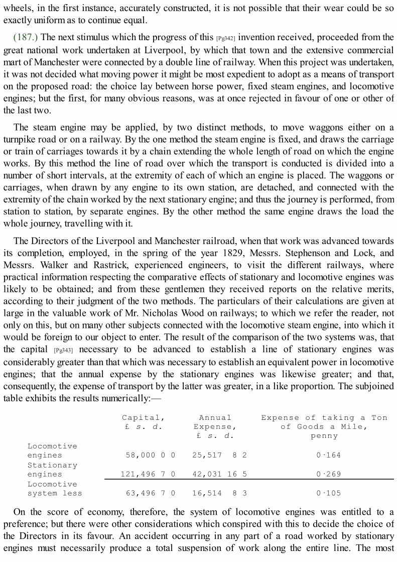
wheels, in the first instance, accurately constructed, it is not possible that their wear could be soexactly uniform as to continue equal.
(187.) The next stimulus which the progress of this [Pg342] invention received, proceeded from thegreat national work undertaken at Liverpool, by which that town and the extensive commercialmart of Manchester were connected by a double line of railway. When this project was undertaken,it was not decided what moving power it might be most expedient to adopt as a means of transporton the proposed road: the choice lay between horse power, fixed steam engines, and locomotiveengines; but the first, for many obvious reasons, was at once rejected in favour of one or other ofthe last two.
The steam engine may be applied, by two distinct methods, to move waggons either on aturnpike road or on a railway. By the one method the steam engine is fixed, and draws the carriageor train of carriages towards it by a chain extending the whole length of road on which the engineworks. By this method the line of road over which the transport is conducted is divided into anumber of short intervals, at the extremity of each of which an engine is placed. The waggons orcarriages, when drawn by any engine to its own station, are detached, and connected with theextremity of the chain worked by the next stationary engine; and thus the journey is performed, fromstation to station, by separate engines. By the other method the same engine draws the load thewhole journey, travelling with it.
The Directors of the Liverpool and Manchester railroad, when that work was advanced towardsits completion, employed, in the spring of the year 1829, Messrs. Stephenson and Lock, andMessrs. Walker and Rastrick, experienced engineers, to visit the different railways, wherepractical information respecting the comparative effects of stationary and locomotive engines waslikely to be obtained; and from these gentlemen they received reports on the relative merits,according to their judgment of the two methods. The particulars of their calculations are given atlarge in the valuable work of Mr. Nicholas Wood on railways; to which we refer the reader, notonly on this, but on many other subjects connected with the locomotive steam engine, into which itwould be foreign to our object to enter. The result of the comparison of the two systems was, thatthe capital [Pg343] necessary to be advanced to establish a line of stationary engines wasconsiderably greater than that which was necessary to establish an equivalent power in locomotiveengines; that the annual expense by the stationary engines was likewise greater; and that,consequently, the expense of transport by the latter was greater, in a like proportion. The subjoinedtable exhibits the results numerically:—
Capital,£ s. d.
AnnualExpense,£ s. d.
Expense of taking a Tonof Goods a Mile,
pennyLocomotiveengines 58,000 0 0 25,517 8 2 0·164Stationaryengines 121,496 7 0 42,031 16 5 0·269Locomotivesystem less 63,496 7 0 16,514 8 3 0·105
On the score of economy, therefore, the system of locomotive engines was entitled to apreference; but there were other considerations which conspired with this to decide the choice ofthe Directors in its favour. An accident occurring in any part of a road worked by stationaryengines must necessarily produce a total suspension of work along the entire line. The most

vigilant and active attention on the part of every workman, however employed, in every part of theline, would therefore be necessary; but, independently of this, accidents arising from the fractureor derangement of any of the chains, or from the suspension of the working of any of the fixedengines, would be equally injurious, and would effectually stop the intercourse along the line. Onthe other hand, in locomotive engines an accident could only affect the particular train of carriagesdrawn by the engine to which the accident might occur; and even then the difficulty could beremedied by having a supply of spare engines at convenient stations along the line. It is true that theprobability of accident is, perhaps, less in the stationary than in the locomotive system; but theinjurious consequences, when accident does happen, are prodigiously greater in the former. "Theone system," says Mr. Walker, "is like a chain extending from Liverpool to Manchester, the failure[Pg344] of a single link of which would destroy the whole; while the other is like a number of shortand unconnected chains," the destruction of any one of which does not interfere with the effect ofthe others, and the loss of which may be supplied with facility.
The decision of the Directors was, therefore, in favour of locomotive engines; and their nextmeasure was to devise some means by which the inventive genius of the country might bestimulated to supply them with the best possible form of engines for this purpose. With this view, itwas proposed and carried into effect to offer a prize for the best locomotive engine which might beproduced under certain proposed conditions, and to appoint a time for a public trial of the claimsof the candidates. A premium of five hundred pounds was accordingly offered for the bestlocomotive engine to run on the Liverpool and Manchester railway; under the condition that itshould produce no smoke; that the pressure of the steam should be limited to fifty pounds on theinch; and that it should draw at least three times its own weight, at the rate of not less than tenmiles an hour; that the engine should be supported on springs, and should not exceed fifteen feet inheight. Precautions were also proposed against the consequences of the boiler bursting; and othermatters not necessary to mention more particularly here. This proposal was announced in thespring of 1829, and the time of trial was appointed in the following October. The engines whichunderwent the trial were, the Rocket, constructed by Mr. Stephenson; the Sanspareil, byHackworth; and the Novelty, by Messrs. Braithwaite and Ericson. Of these, the Rocket obtainedthe premium. A line of railway was selected for the trial, on a level piece of road about two milesin length, near a place called Rainhill, between Liverpool and Manchester; the distance betweenthe two stations was a mile and a half, and the engine had to travel this distance backwards andforwards ten times, which made altogether a journey of thirty miles. The Rocket performed thisjourney twice: the first time in 2 hours 14 minutes and 8 seconds; and the second time in 2 hours 6minutes and 49 seconds. Its speed at different parts of the journey varied: its greatest rate ofmotion was [Pg345] rather above 29 miles an hour; and its least, about 111⁄2 miles an hour. Theaverage rate of the one journey was 134⁄10 miles an hour; and of the other, 142⁄20 miles. This wasthe only engine which performed the complete journey proposed, the others having been stoppedfrom accidents which occurred to them in the experiment. The Sanspareil performed the distancebetween the stations eight times, travelling 221⁄2 miles in 1 hour 37 minutes and 16 seconds. Thegreatest velocity to which this engine attained was something less than 23 miles per hour. TheNovelty had only passed twice between the stations when the joints of the boiler gave way, and putan end to the experiment.
(188.) The great object to be attained in the construction of these engines was, to combine withsufficient lightness the greatest possible heating power. The fire necessarily acts on the water in
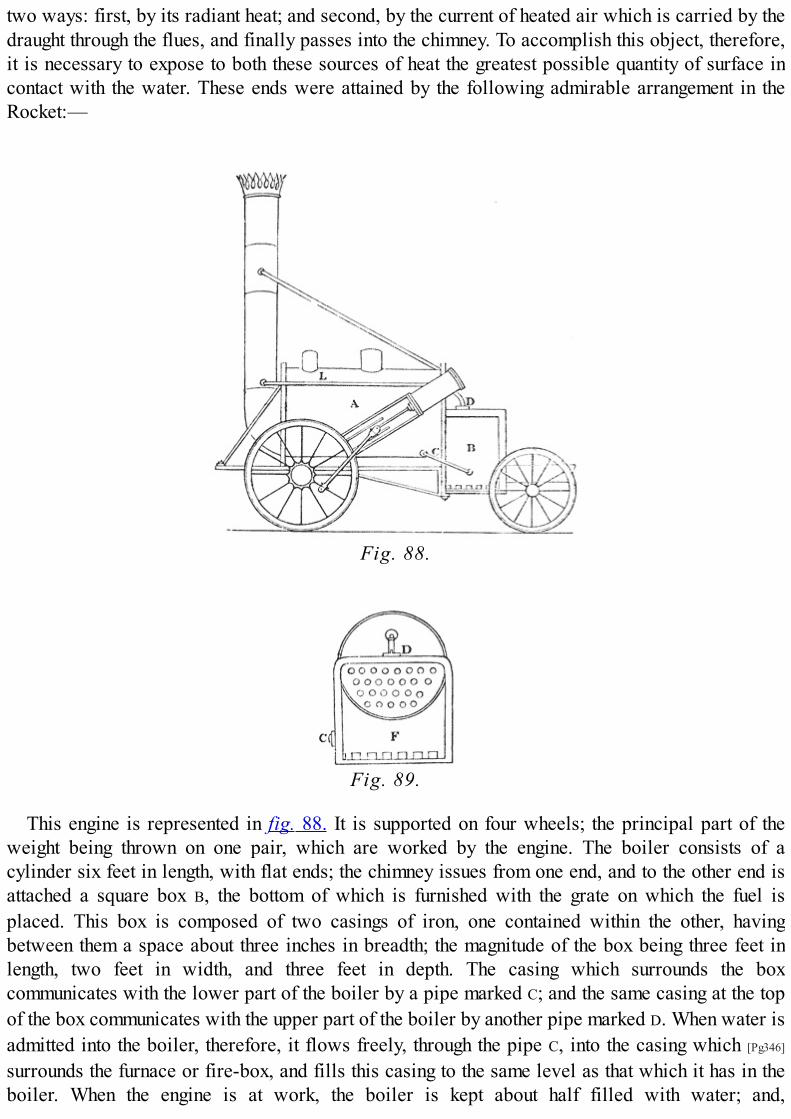
two ways: first, by its radiant heat; and second, by the current of heated air which is carried by thedraught through the flues, and finally passes into the chimney. To accomplish this object, therefore,it is necessary to expose to both these sources of heat the greatest possible quantity of surface incontact with the water. These ends were attained by the following admirable arrangement in theRocket:—
Fig. 88.
Fig. 89.
This engine is represented in fig. 88. It is supported on four wheels; the principal part of theweight being thrown on one pair, which are worked by the engine. The boiler consists of acylinder six feet in length, with flat ends; the chimney issues from one end, and to the other end isattached a square box B, the bottom of which is furnished with the grate on which the fuel isplaced. This box is composed of two casings of iron, one contained within the other, havingbetween them a space about three inches in breadth; the magnitude of the box being three feet inlength, two feet in width, and three feet in depth. The casing which surrounds the boxcommunicates with the lower part of the boiler by a pipe marked C; and the same casing at the topof the box communicates with the upper part of the boiler by another pipe marked D. When water isadmitted into the boiler, therefore, it flows freely, through the pipe C, into the casing which [Pg346]
surrounds the furnace or fire-box, and fills this casing to the same level as that which it has in theboiler. When the engine is at work, the boiler is kept about half filled with water; and,

consequently, the casing surrounding the furnace is completely filled. The steam which is generatedin the water contained in the casing finds its exit through the pipe D, and escapes into the upper partof the boiler. A section of the engine, taken at right angles to its length, is represented at fig. 89.Through the lower part of the boiler pass a number of copper tubes of small size, whichcommunicate at one end with the fire-box, and at the other with the chimney, and form a passagefor the heated air from the furnace to the chimney. The ignited fuel spread on the grate at the bottomof the fire-box disperses its heat by radiation, and acts in this manner on the whole surface of thecasing surrounding the fire-box; and thus raises the temperature of the thin shell of water containedin that casing. The chief [Pg347] part of the water in the casing, being lower in its position than thewater in the boiler, acquires a tendency to ascend when heated, and passes into the boiler; so that aconstant circulation of the heated water is maintained, and the water in the boiler must necessarilybe kept at nearly the same temperature as the water in the casing. The air which passes through theburning fuel, and which fills the fire-box, is carried by the draught through the tubes which extendthrough the lower part of the boiler; and as these tubes are surrounded on every side with the watercontained in the boiler, this air transmits its heat through these tubes to the water. It finally issuesinto the chimney, and rises by the draught. The power of this furnace must necessarily depend onthe power of draught in the chimney; and to increase this, and at the same time to dispose of thewaste steam after it has worked the piston, this steam is carried off by a pipe L, which passes fromthe cylinder to the chimney, and escapes there in a jet which is turned upwards. By the velocitywith which it issues from this jet, and by its great comparative levity, it produces a strong currentupwards in the chimney, and thus gives force to the draught of the furnace. In fig. 89. the grate-barsare represented at the bottom of the fire-box at F. There are two cylinders, one of which workseach wheel; one only appearing in the drawing fig. 88., the other being concealed by the engine.The spokes which these cylinders work are placed at right angles on the wheels; the wheels beingfixed on a common axle, with which they turn.
In this engine, the surface of water surrounding the fire-box, exposed to the action of radiantheat, amounted to twenty square feet, which received heat from the surface of six square feet ofburning fuel on the bars. The surface exposed to the action of the heated air amounted to 118square feet. The engine drew after it another carriage, containing fuel and water; the fuel used wascoke, for the purpose of avoiding the production of smoke.
(189.) The Sanspareil of Mr. Hackworth is represented in fig. 90.; the horizontal section beingexhibited in fig. 91.

Fig. 90.
Fig. 91.
The draught of the furnace is produced in the same manner as in the Rocket, by ejecting thewaste steam coming from [Pg348] the cylinder into the chimney; the boiler, however, differsconsiderably from that of the Rocket. A recurved tube passes through the boiler, somewhat similarto that already described in the early engine of Messrs. Trevethick and Vivian. In the horizontalsection (fig. 91.), D expresses the opening of the furnace at the end of the boiler, beside thechimney. The grate-bars appear at A, supporting the burning fuel; and a curved tube passing throughthe boiler, and terminating in the chimney, is expressed at B, the direction [Pg349] of the draught beingindicated by the arrow; C is a section of the chimney. The cylinders are placed, as in the Rocket, oneach side of the boiler; each working a separate wheel, but acting on spokes placed at right anglesto each other. The tube in which the grate and flue are placed diminishes in diameter as itapproaches the chimney. At the mouth where the grate was placed, its diameter was two feet; and itwas gradually reduced, so that, at the chimney, its diameter was only fifteen inches. The grate-barsextended five feet into the tube. The surface of water exposed to the radiant heat of the fire wassixteen square feet; and that exposed to the action of the heated air and flame was about seventy-five square feet. The magnitude of the grate, or sheet of burning fuel which radiated heat, was ten

square feet.
(190.) The Novelty, of Messrs. Braithwaite and Ericson, is represented in fig. 92.; and a sectionof the generator and boiler is exhibited in fig. 93.; the corresponding parts in the two figures aremarked by the same letters.
Fig. 92.
A is the generator or receiver containing the steam which works the engine; this communicateswith a lower generator B, which extends in a horizontal direction the entire length of the carriage.Within the generator A is contained the furnace F, which communicates in a tube C, carried upthrough the generator, and terminated at the top by sliding shutters, which exclude the air, andwhich are only opened to supply fuel to the grate F. Below the grate the furnace is not open, asusual, to the atmosphere, but communicates, [Pg350] by a tube E, with a bellows D; which is workedby the engine, and which forces a constant stream of air, by the tube E, through the fuel on F, so asto keep that fuel in vivid combustion. The heated air contained in the furnace F is driven on, by thesame force, through a small curved tube marked e, which circulates like a worm (as represented infig. 93.) through the horizontal generator or receiver; and, tapering gradually, until reduced to verysmall dimensions, it finally issues into the chimney G. The air in passing along this tube, imparts itsheat to the water by which the tube is surrounded, and is brought to a considerably reducedtemperature when discharged into the chimney. The cylinder, which is represented at K, works onepair of wheels, by means of a bell-crank, the other pair, when necessary, being connected withthem.
Fig. 93.

In this engine, the magnitude of the surface of burning fuel on the grate-bars is less than twosquare feet; the surface exposed to radiant heat is nine and a half square feet; and the surface ofwater exposed to heated air is about thirty-three square feet.
The superiority of the Rocket may be attributed chiefly to the greater quantity of surface of thewater which is exposed to the action of the fire. With a less extent of grate-bars than theSanspareil, in the proportion of three to five, it exposes a greater surface of water to radiant heat,in the proportion of four to three; and a greater surface of water to heated air, in the proportion ofmore than three to two. It was found that the Rocket, compared with the Sanspareil, consumed fuel,in the evaporation of a given quantity of water, [Pg351] in the proportion of eleven to twenty-eight.The suggestion of using the tubes to conduct through the water the heated air to the chimney is dueto Mr. Booth, treasurer of the Liverpool and Manchester Railway Company.
(191.) The object to be effected in the boilers of these engines is, to keep a small quantity ofwater at an excessive temperature, by means of a small quantity of fuel kept in the most active stateof combustion. To accomplish this, it is necessary, first, so to shape the boiler, furnace, and flues,that the water shall be in contact with as extensive a surface as possible, every part of which isacted on, either immediately, by the heat radiating from the fire, or mediately, by the air which haspassed through the fire, and which finally rushes into the chimney: and, secondly, that such aforcible draught should be maintained in the furnace, that a quantity of heat shall be extricated fromthe fuel, by combustion, sufficient to maintain the water at the necessary temperature, and toproduce the steam with sufficient rapidity. To accomplish these objects, therefore, the chambercontaining the grate should be completely surrounded by water, and should be below the level ofthe water in the boiler. The magnitude of the surface exposed to radiation should be as great as isconsistent with the whole magnitude of the machine. The comparative advantage which the Rocketpossessed in these respects over the other engines will be evident on inspection. In the next place,it is necessary that the heat, which is absorbed by the air passing through the fuel, and keeping it ina state of combustion, should be transferred to the water before the air escapes into the chimney.Air being a bad conductor of heat, to accomplish this it is necessary that the air in the flues shouldbe exposed to as great an extent of surface in contact with the water as possible. No contrivancecan be less adapted for the attainment of this end than one or two large tubes traversing the boiler,as in the earliest locomotive engines: the body of air which passed through the centre of thesetubes had no contact with their surface, and, consequently, passed into the chimney at nearly thesame temperature as that which it had when it quitted the fire. The only portion of air whichimparted its heat to the water [Pg352] was that portion which passed next to the surface of the tube.
Several methods suggest themselves to increase the surface of water in contact with a givenquantity of air passing through it. This would be accomplished by causing the air to pass betweenplates placed near each other, so as to divide the current into thin strata, having between themstrata of water, or it might be made to pass between tubes differing slightly in diameter, the waterpassing through an inner tube, and being also in contact with the external surface of the outer tube.Such a method would be similar in principle to the steam-jacket used in Watt's steam engines, or tothe condenser of Cartwright's engine already described. But, considering the facility ofconstructing small tubes, and of placing them in the boiler, that method, perhaps, is, on the whole,the best in practice; although the shape of a tube, geometrically considered, is most unfavourablefor the exposure of a fluid contained in it to its surface. The air which passes from the fire-chamber, being subdivided as it passes through the boiler by a great number of very small tubes,

may be made to impart all its excess of heat to the water before it issues into the chimney. This isall which the most refined contrivance can effect. The Rocket engine was traversed by twenty-fivetubes, each three inches in diameter; and the principle has since been carried to a much greaterextent.
The abstraction of a great quantity of heat from the air before it reaches the chimney is attendedwith one consequence, which, at first view, would present a difficulty apparently insurmountable;the chimney would, in fact, lose its power of draught. This difficulty, however, was removed byusing the waste steam, which had passed from the cylinder after working the engine, for thepurpose of producing a draught. This steam was urged through a jet presented upwards in thechimney, and driven out with such force in that direction as to create a sufficient draught to workthe furnace.
It will be observed that the principle of draught in the Novelty is totally distinct from this: in thatengine the draught is produced by a bellows worked by the engine. The question, as far as relatesto these two methods, is, whether more power [Pg353] is lost in supplying the steam through the jet,as in the Rocket, or in working the bellows, as in the Novelty. The force requisite to impel thesteam through the jet must be exerted by the returning stroke of the piston, and, consequently, mustrob the working effect to an equivalent amount. On the other hand, the power requisite to work thebellows in the Novelty must be subducted from the available power of the engine. The formermethod has been hitherto found to be the more effectual and economical.
The importance of these details will be understood, when it is considered that the only limit tothe attainment of speed by locomotive engines is the power to produce, in a given time, a certainquantity of steam. Each stroke of the piston causes one revolution of the wheels, and consumes fourcylinders full of steam: consequently, a cylinder of steam corresponds to a certain number of feetof road travelled over: hence it is that the production of a rapid and abundant supply of heat, andthe imparting of that heat quickly and effectually to the water, is the key to the solution of theproblem to construct an engine capable of rapid motion.
The method of subdividing the flue into tubes was carried much further by Mr. Stephenson afterthe construction of the Rocket; and, indeed, the principle was so obvious, it is only surprising that,in the first instance, tubes of smaller diameter than three inches were not used. In engines sinceconstructed, the number of tubes vary from ninety to one hundred and twenty, the diameter beingreduced to two inches or less; and in some instances tubes have been introduced, even to thenumber of one hundred and fifty, of one and a half inch diameter. In the Meteor, twenty square feetare exposed to radiation, and one hundred and thirty-nine to the contact of heated air; in the Arrow,twenty square feet to radiation, and one hundred and forty-five to the contact of heated air. Thesuperior economy of fuel gained by this means will be apparent by inspecting the following table,which exhibits the consumption of fuel which was requisite to convey a ton weight a mile in eachof four engines, expressing also the rate of the motion:— [Pg354]
Engines. Average Rate of Speedin Miles per Hour.
Consumption of Coke inPounds per Ton per Mile.
No. 1. Rocket 14 2·41 2. Sanspareil 15 2·47 3. Phœnix 12 1·42 4. Arrow 12 1·25
(192.) Since the period at which this railway was opened for the actual purposes of transport,

the locomotive engines have been in a state of progressive improvement. Scarcely a month haspassed without suggesting some change in the details, by which fuel might be economised, theproduction of steam rendered more rapid, the wear of the engine rendered slower, theproportionate strength of the different parts improved, or some other desirable end obtained.
Engines constructed in the form of the Rocket, were subject to two principal defects. Thecylinders, being placed outside the engine, were exposed to the cold of the atmosphere, whichproduced a waste of heat more or less considerable by condensation. The points at which thepower of the steam to turn the wheels was applied, being at the extremities of the axle and on theexterior of the wheel, a considerable strain was produced, owing to the distance of the point ofapplication of the power from the centre of resistance. If it were possible that the impelling powercould act in drawing the train at all times with equal energy on both sides of the engine, then noinjurious strain would be produced; but from the relative position of the points on the oppositewheels to which it was necessary to attach the connecting rods, it was inevitable that, at themoment when one of the pistons exerts its full power in driving the wheel, the other piston must bealtogether inactive. The impelling power, therefore, at alternate moments of time, acted onopposite wheels, and on each of them at the greatest possible distance from the centre of the axle.
Fig. 94.
(193.) The next step in the improvement of the machine was made with a view to remove thesetwo defects. The cylinders were transferred from the exterior of the engine to the [Pg355] interior ofthe casing called the smoke-box, B, fig. 94., which supports the chimney, and which receives theheated air issuing from the tubes which traverse the boiler. Thus placed, the cylinders are alwaysmaintained as hot as the air which issues from the flues, and all condensation of steam by theirexposure is prevented. The piston-rods are likewise brought closer together, and nearer the centreof the engine: the connecting rods, no longer attached to the wheels, are made to act upon twocranks constructed upon the axle of the wheels, and placed at right angles to each other. From theposition of these cranks, one would always be at its dead point when the other is in full action. Theaction of the steam upon them would, therefore, be generally unequal; but this would not producethe same strain as when the connecting rods are attached to points upon the exterior of the wheels,

owing to the cranks being constructed on the axle at points so much nearer its centre. By this meansit was found that the working of the machine was more even, and productive of much less strain,than in the arrangement adopted in the Rocket, and the earlier engines. On the other hand, a seriousdisadvantage was incurred by a double-cranked axle. The weakness necessarily arising from sucha form of axle could only be removed by great thickness [Pg356] and weight of metal; and even thisprecaution, at first, did not prevent their occasional fracture. The forging of them was, however,subsequently much improved: the cranks, instead of being formed by bending the metal whensoftened by heat, were made by cutting the square of the crank out of the solid metal; and now itrarely happens that one of these axles fails.
The adoption of smaller tubes, and a greater number of them, with a view more perfectly toextract the heat from the air in passing to the chimney, rendered a more forcible draft necessary.This was accomplished by the adoption of a more contracted blast-pipe leading from the eduction-pipes of the cylinders and presented up the chimney. A representation of such a blast-pipe, with thetwo tubes leading from the cylinders and uniting together near the point, which is presented up thechimney, is given at p p in fig. 104. The engine thus improved is represented in fig. 94.
A represents the cylindrical boiler, the lower half of which is traversed by tubes, as described inthe Rocket. They are usually from eighty to one hundred in number, and about an inch and a half indiameter; the boiler is about seven feet in length; the fire-chamber is attached to one end of it, at F,as in the Rocket, and similar in construction: the cylinders are inserted in a chamber at the otherend, immediately under the chimney. The piston-rods are supported in the horizontal position byguides; and connecting rods extend from them, under the engine, to the two cranks placed on theaxle of the large wheels. The effects of an inequality in the road are counteracted by springs, onwhich the engine rests; the springs being below the axle of the great wheels, and above that of theless. The steam is supplied to the cylinders, and withdrawn, by means of the common slidingvalves, which are worked by an eccentric wheel placed on the axle of the large wheels of thecarriage. The motion is communicated from this eccentric wheel to the valve by sliding rods. Thestand is placed for the attendant at the end of the engine, next the fire-place F; and two levers L
project from the end which communicate with the valves by means of rods, by which the engine isgoverned so as to reverse the motion. [Pg357]
The wheels of these engines have been commonly constructed of wood with strong iron ties,furnished with flanges adapted to the rails. But Mr. Stephenson afterward substituted, in someinstances, wheels of iron with hollow spokes. The engine draws after it a tender carriagecontaining the fuel and water; and, when carrying a light load, is capable of performing the wholejourney from Liverpool to Manchester without a fresh supply of water. When a heavy load ofmerchandise is drawn, it is usual to take in water at the middle of the trip.
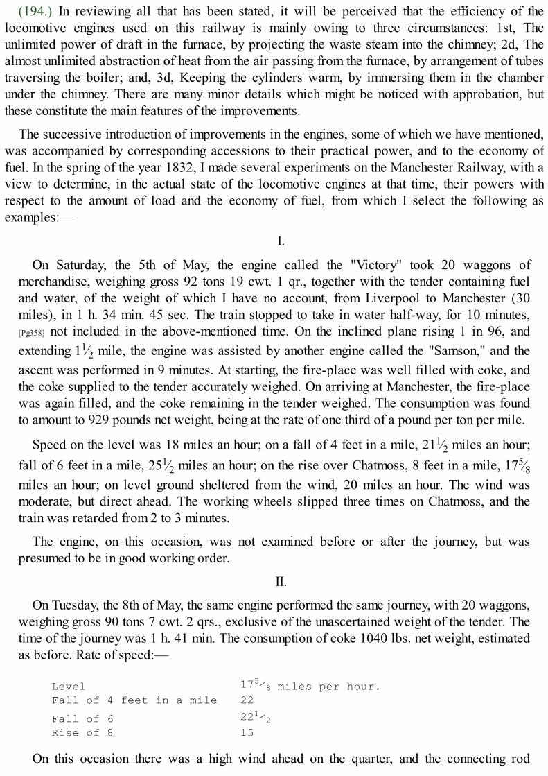
(194.) In reviewing all that has been stated, it will be perceived that the efficiency of thelocomotive engines used on this railway is mainly owing to three circumstances: 1st, Theunlimited power of draft in the furnace, by projecting the waste steam into the chimney; 2d, Thealmost unlimited abstraction of heat from the air passing from the furnace, by arrangement of tubestraversing the boiler; and, 3d, Keeping the cylinders warm, by immersing them in the chamberunder the chimney. There are many minor details which might be noticed with approbation, butthese constitute the main features of the improvements.
The successive introduction of improvements in the engines, some of which we have mentioned,was accompanied by corresponding accessions to their practical power, and to the economy offuel. In the spring of the year 1832, I made several experiments on the Manchester Railway, with aview to determine, in the actual state of the locomotive engines at that time, their powers withrespect to the amount of load and the economy of fuel, from which I select the following asexamples:—
I.
On Saturday, the 5th of May, the engine called the "Victory" took 20 waggons ofmerchandise, weighing gross 92 tons 19 cwt. 1 qr., together with the tender containing fueland water, of the weight of which I have no account, from Liverpool to Manchester (30miles), in 1 h. 34 min. 45 sec. The train stopped to take in water half-way, for 10 minutes,[Pg358] not included in the above-mentioned time. On the inclined plane rising 1 in 96, andextending 11⁄2 mile, the engine was assisted by another engine called the "Samson," and theascent was performed in 9 minutes. At starting, the fire-place was well filled with coke, andthe coke supplied to the tender accurately weighed. On arriving at Manchester, the fire-placewas again filled, and the coke remaining in the tender weighed. The consumption was foundto amount to 929 pounds net weight, being at the rate of one third of a pound per ton per mile.
Speed on the level was 18 miles an hour; on a fall of 4 feet in a mile, 211⁄2 miles an hour;fall of 6 feet in a mile, 251⁄2 miles an hour; on the rise over Chatmoss, 8 feet in a mile, 175⁄8miles an hour; on level ground sheltered from the wind, 20 miles an hour. The wind wasmoderate, but direct ahead. The working wheels slipped three times on Chatmoss, and thetrain was retarded from 2 to 3 minutes.
The engine, on this occasion, was not examined before or after the journey, but waspresumed to be in good working order.
II.
On Tuesday, the 8th of May, the same engine performed the same journey, with 20 waggons,weighing gross 90 tons 7 cwt. 2 qrs., exclusive of the unascertained weight of the tender. Thetime of the journey was 1 h. 41 min. The consumption of coke 1040 lbs. net weight, estimatedas before. Rate of speed:—
Level 175⁄8 miles per hour.Fall of 4 feet in a mile 22
Fall of 6 221⁄2Rise of 8 15
On this occasion there was a high wind ahead on the quarter, and the connecting rod

worked hot, owing to having been keyed too tight. On arriving at Manchester, I caused thecylinders to be opened, and found that the pistons were [Pg359] so loose, that the steam blewthrough the cylinders with great violence. By this cause, therefore, the machine was robbed ofa part of its power during the journey; and this circumstance may explain the slight decreasein speed, and increase in the consumption of fuel, with a lighter load, in this journey,compared with that performed on the 5th of May.
The Victory weighs 8 tons 2 cwt., of which 5 tons 4 cwt. rest on the drawing wheels. Thecylinders are 11 inches diameter, and 16 inches stroke, and the diameter of the drawingwheels is 5 feet.
III.
On the 29th of May, the engine called the "Samson" (weighing 10 tons 2 cwt., with 14-inchcylinders, and 16-inch stroke; wheels 4 feet 6 inches diameter, both pairs being worked bythe engine; steam 50 lbs. pressure, 130 tubes) was attached to 50 waggons, laden withmerchandise; net weight about 150 tons; gross weight, including waggons, 223 tons 6 cwt.The tender weighed 7 tons, making a gross load (including the engine) of 240 tons 8 cwt. Theengine with this load travelled from Liverpool to Manchester (30 miles) in 2 hours and 40min., exclusive of delays upon the road for watering, &c.; being at the rate of nearly 12 milesan hour. The speed varied according to the inclinations of the road. Upon a level, it was 12miles an hour; upon a descent of 6 feet in a mile, it was 16 miles an hour; upon a rise of 8 feetin a mile, it was about 9 miles an hour. The weather was calm, the rails very wet; but thewheels did not slip, even in the slowest speed, except at starting, the rails being at that placesoiled and greasy with the slime and dirt to which they are always exposed at the stations.The coke consumed in this journey, exclusive of what was raised in getting up the steam, was1762 lbs., being at the rate of a quarter of a pound per ton per mile.
(195.) The great original cost, and the heavy expense of keeping the engines used on the railwayin repair, have pressed severely on the resources of the undertaking. One of the best [Pg360]
constructed of the later engines costs originally 1500l. and sometimes more. The original cost,however, is far from being the principal source of expense: the wear and tear of these machines,and the occasional fracture of those parts on which the greatest strain has been laid, have greatlyexceeded what the directors had anticipated. Although this source of expense must be in partattributed to the engines not having yet attained that state of perfection, in the proportion andadjustment of their parts, of which they are susceptible, and to which experience alone can lead,yet there are some obvious defects which demand attention.
The heads of the boilers are flat, and formed of iron, similar to the material of the boilersthemselves. The tubes which traverse the boiler were, until recently, copper, and so inserted intothe flat head or end as to be water-tight. When the boiler was heated, the tubes were found toexpand in a greater degree than the other parts of the boiler; which frequently caused them either tobe loosened at the extremities, so as to cause leakage, or to bend from want of room for expansion.The necessity of removing and refastening the tubes caused, therefore, a constant expense.
It will be recollected that the fire-place is situated at one end of the boiler, immediately belowthe mouths of the tubes: a powerful draft of air, passing through the fire, carries with it ashes andcinders, which are driven violently through the tubes, and especially the lower ones, situated nearthe fuel. These tubes are, by this means, subject to rapid wear, the cinders continually acting upon
their interior surface. After a short time it becomes necessary to replace single tubes, according asthey are found to be worn, by new ones; and it not unfrequently happens, when this is neglected,that tubes burst. After a certain length of time the engines require new tubing. This wear of thetubes might possibly be avoided by constructing the fire-place in a lower position, so as to bemore removed from their mouths; or, still more effectually, by interposing a casing of metal, whichmight be filled with water, between the fire-place and those tubes which are the most exposed tothe cinders and ashes. The unequal expansion of the tubes [Pg361] and boilers appears to be anincurable defect, if the present form of the engine be retained. If the fire-place and chimney couldbe placed at the same end of the boiler, so that the tubes might be recurved, the unequal expansionwould then produce no injurious effect; but it would be difficult to clean the tubes, if they wereexposed, as they are at present, to the cinders. The next source of expense arises from the wear ofthe boiler-heads, which are exposed to the action of the fire.
A considerable improvement was subsequently introduced into the method of tubing, bysubstituting brass for copper tubes. I am not aware that the cause of this improvement has beendiscovered; but it is certain, whatever be the cause, that brass tubes are subject to considerablyslower wear than copper ones.
(196.) The expense of locomotive power having so far exceeded what was anticipated at thecommencement of the undertaking, it was thought advisable, about the beginning of the year 1834,to institute an inquiry into the causes which produced the discrepancy between the estimated andactual expenses, with a view to the discovery of some practical means by which they could bereduced. The directors of the company, for this purpose, appointed a sub-committee of their ownbody, assisted by Mr. Booth, their treasurer, to inquire and report respecting the causes of theamount of this item of their expenditure, and to ascertain whether any and what measures could bedevised for the attainment of greater economy. A very able and satisfactory report was made bythis committee, or, to speak more correctly, by Mr. Booth.
It appears that, previous to the establishment of the railway, Messrs. Walker and Rastrick,engineers, were employed by the company to visit various places where steam power was appliedon railways, for the purpose of forming an estimate of the probable comparative expense ofworking the railway by locomotive and by fixed power. These engineers recommended theadoption of locomotive power; and their estimate was, that the transport might be effected at therate of ·278 of a penny, or very little more than a farthing per ton per mile. In the year [Pg362] 1833,five years after this investigation took place, it was found that the actual cost was ·625 of a penny,or something more than a halfpenny, per ton per mile, being considerably above double theestimated rate. Mr. Booth very properly directed his inquiries to ascertain the cause of thisdiscrepancy, by comparing the various circumstances assumed by Messrs. Walker and Rastrick, inmaking their estimate, with those under which the transport was actually effected. The first point ofdifference which he observed was the speed of transport: the estimate was founded on an assumedspeed of ten miles an hour, and it was stated that a four-fold speed would require an addition of 50per cent. to the power, without taking into account wear and tear. Now, the actual speed oftransport being double the speed assumed in the statement, Mr. Booth holds it to be necessary toadd 25 per cent. on that score.
The next point of difference is in the amount of the loads: the estimate is founded upon theassumption, that every engine shall start with its full complement of load, and that with this it shallgo the whole distance. "The facts, however, are," says Mr. Booth, "that, instead of a full load of

profitable carriage from Manchester, about half the waggons come back empty; and, instead of thetonnage being conveyed the whole way, many thousand tons are conveyed only half the way; also,instead of the daily work being uniform, it is extremely fluctuating." It is further remarked, that inorder to accomplish the transport of goods from the branches and from intermediate places,engines are despatched several times a-day, from both ends of the line, to clear the road; theobject of this arrangement being rather to lay the foundation of a beneficial intercourse in future,than with a view to any immediate profit. Mr. Booth makes a rough estimate of the disadvantagesarising from these circumstances, by stating them at 33 per cent. in addition to the originalestimate.
The next point of difference is the fuel. In the original estimate, coal is assumed as the fuel, andit is taken at the price of five shillings and ten-pence per ton: now the act of parliament forbids theuse of coal which would produce smoke; the company have, therefore, been obliged to use coke, at[Pg363] seventeen shillings and sixpence a ton.[32] Taking coke, then, to be equivalent to coal, ton forton, this would add ·162 to the original estimate.
These several discrepancies being allowed for, and a proportional amount being added to theoriginal estimate, the amount would be raised to ·601 of a penny per ton per mile, which is withinone fortieth of a penny of the actual cost. This difference is considered to be sufficiently accountedfor by the wear and tear produced by the very rapid motion, more especially when it is consideredthat many of the engines were constructed before the engineer was aware of the great speed thatwould be required.
"What, then," says Mr. Booth, in the Report already alluded to, "is the result of these oppositeand mutually counteracting circumstances? and what is the present position of the company inrespect of their moving power? Simply, that they are still in a course of experiment, to ascertainpractically the best construction, and the most durable materials, for engines required to transportgreater weights, and at greater velocities, than had, till very recently, been considered possible;and which, a few years ago, it had not entered into the imagination of the most daring and sanguineinventor to conceive: and farther, that these experiments have necessarily been made, not with thecalm deliberation and quiet pace which a salutary caution recommends,—making good each stepin the progress of discovery before advancing another stage,—but amidst the bustle andresponsibilities of a large and increasing traffic; the directors being altogether ignorant of the timeeach engine would last before it would be laid up as inefficient, but compelled to have engines,whether good or bad; being aware of various defects and imperfections, which it was impossibleat the time to remedy, yet obliged to keep the machines in motion, under all the disadvantages ofheavy repairs, constantly going on during the night, in order that the requisite number of enginesmight be ready for the morning's work. Neither is this great experiment yet complete; it is stillgoing forward. But the most prominent difficulties have been in a great measure surmounted, [Pg364]
and your committee conceive that they are warranted in expecting, that the expenditure in thisdepartment will, ere long, be materially reduced,—more especially when they consider therelative performances of the engines at the present time, compared with what it was two yearsago."
In the half year ending 31st December, 1831, the six best engines performed as follows:—
Miles.Planet 9,986Mercury 11,040

Jupiter 11,618Saturn 11,786Venus 12,850Etna 8,764Making in all 66,044
In the half year ending 31st December, 1833, the six best engines performed as follows:—
Miles.Jupiter 16,572Saturn 18,678Sun 14,552Etna 17,763Ajax 11,678Firefly 15,608Making in all 95,851
(197.) Since the date to which the preceding observations refer, the locomotive engine hasundergone several improvements in detail of considerable importance; among which, the additionof a third pair of wheels deserves to be particularly mentioned. An engine supported on three pairof wheels has great security in the event of the fracture of any one of the axles,—the remainingaxles and wheels being sufficient for the support of the machine. Connected with this change isanother, recommended by Mr. Robert Stephenson, by which the flanges are removed from thedriving wheels, those upon the remaining pairs of wheels being sufficient to keep the engine in itsposition upon the rails. We shall now describe a locomotive engine similar in construction to thosealmost [Pg365] universally used at present on railroads, as well in this kingdom as in other countries.[33]
The external appearance of the engine and tender is shown in the engraving at the head of thischapter. In fig. 97. is exhibited a vertical section of the engine made by a plane carried through itslength; and in fig. 98. is exhibited a corresponding section of its tender,—the tender beingsupposed to be joined on to the engine at the part where the connecting points appear to be brokenin the drawing. In fig. 99. is exhibited the plan of the working machinery, including the cylinders,pistons, eccentrics, &c. which are under the boiler, by the operation of which the engine is driven.Fig. 100. represents the tender, also taken in plan.
In fig. 101. is represented an elevation of the hinder end of the engine next the fire-box; and infig. 102. is represented a cross vertical section through the fire-box, and at right angles to thelength of the engine, showing the interior of the boiler above and beside the fire-box, the rivets andbolts connecting the internal and external fire-boxes, the regulator, steam funnel, and steam dome.
In fig. 103. is represented an elevation of the front of the engine next the smoke-box, showing thecylinder covers W, buffers T, &c.; and in fig. 104. is represented a section of the interior of thesmoke-box, made by a vertical plane at right angles to the engine, showing the tube plate formingthe foremost end of the boiler, the branches S of the steam-pipe leading to the cylinders, the blast-pipe p, the cylinders H, and the chimney G.
The same letters of reference are placed at corresponding parts in the different figures.
The boiler, as has been explained in the engines already described, is a cylinder placed upon itsside, the section of which is exhibited at A, fig. 97. The fire-box consists of two casings of metal,

one within the other. The fire-grate is represented at D. The tubes by which the products ofcombustion are [Pg366] drawn from the fire-box to the smoke-box F are represented at E. Upon thesmoke-box is erected the chimney G. In the engine from which this drawing has been taken, andwhich was used on the London and Birmingham Railway, the boiler is a cylinder 71⁄2 feet long, and31⁄2 feet in diameter. It is formed of wrought-iron plates 5⁄16 of an inch in thickness, overlappingeach other, and bound together by iron rivets 7⁄8 of an inch in diameter and 13⁄4 inch apart. One ofthese rivets, as it joins two plates, is represented in fig. 95. The boiler is clothed with a boardingof wood a, an inch in thickness, and bound round by iron hoops screwed together at the bottom.Wood being a slow conductor of heat, this covering has the effect of keeping the boiler warm, andchecking the condensation of steam which would otherwise be produced by the rapid motion of theengine through the cold air.
Fig. 95.
Fig. 96.
The external fire-box, B B, is a casing nearly square in its plan, being four feet wide outside, andthree feet seven and a half inches long, measured in the direction of the boiler. It is constructed ofwrought-iron plates, similar to those of the boiler. This box descends about two feet below theboiler, the top being semi-cylindrical, as seen in fig. 102., of a somewhat greater diameter than theboiler, and concentrical with it. The front of the fire-box next the end of the boiler has a circularopening equal in size to the end of the boiler. To the edge of this opening the boiler is fastened byangle irons, and rivets in the manner represented in fig. 96. These rivets are seen in section in fig.97.
The internal fire-box C, fig. 97., is similar in shape to the external, only it is flat at the top, andclose every where except at the bottom. Between it and the external fire-box an open space ofthree inches and a half is left all round, and on the side next the boiler this space is increased tofour inches. This internal fire-box is made of copper plates, 7⁄16 [Pg367] of an inch in thickness, everywhere except next the boiler, where the thickness is 7⁄8.
As the sides and front of the external fire-box, and all the surfaces bounding the internal fire-box, are flat, their form is unfavourable for the resistance of pressure. Adequate means are,therefore, provided for strengthening them. The plates forming the internal fire-box are bentoutwards near the bottom, until they are brought into contact with those of the external fire-box, to

which they are attached by copper rivets, as represented at f in fig. 97. The plates forming thebounding surfaces of the two fire-boxes are fastened together by stays represented at k in figs. 97.and 102. These stays, which are of copper, have a screw cut upon them through their whole length,and holes are made through the plates of both fire-boxes tapped with corresponding threads. Thecopper screws are then passed through them, and rivets formed on their heads within and without,as seen in fig. 102. These screw rivets connect all parts of the plating of the two fire-boxes whichare opposed to each other: they are placed at about four inches apart over the sides and back of theinternal fire-place and that part of the front which is below the boiler.
Fig. 97. LONGITUDINAL VERTICAL SECTION OF A LOCOMOTIVE ENGINE.
Fig. 98. LONGITUDINAL VERTICAL SECTION OF THE TENDER.

Fig. 99. PLAN OF THE WORKING MACHINERY OF A LOCOMOTIVE ENGINE.
Fig. 100. PLAN OF THE TENDER.

Fig. 101. ELEVATION OF THE HINDER END OF A LOCOMOTIVE ENGINE.

Fig. 102. CROSS VERTICAL SECTION OF THE ENGINE THROUGH THE FIRE-BOX.
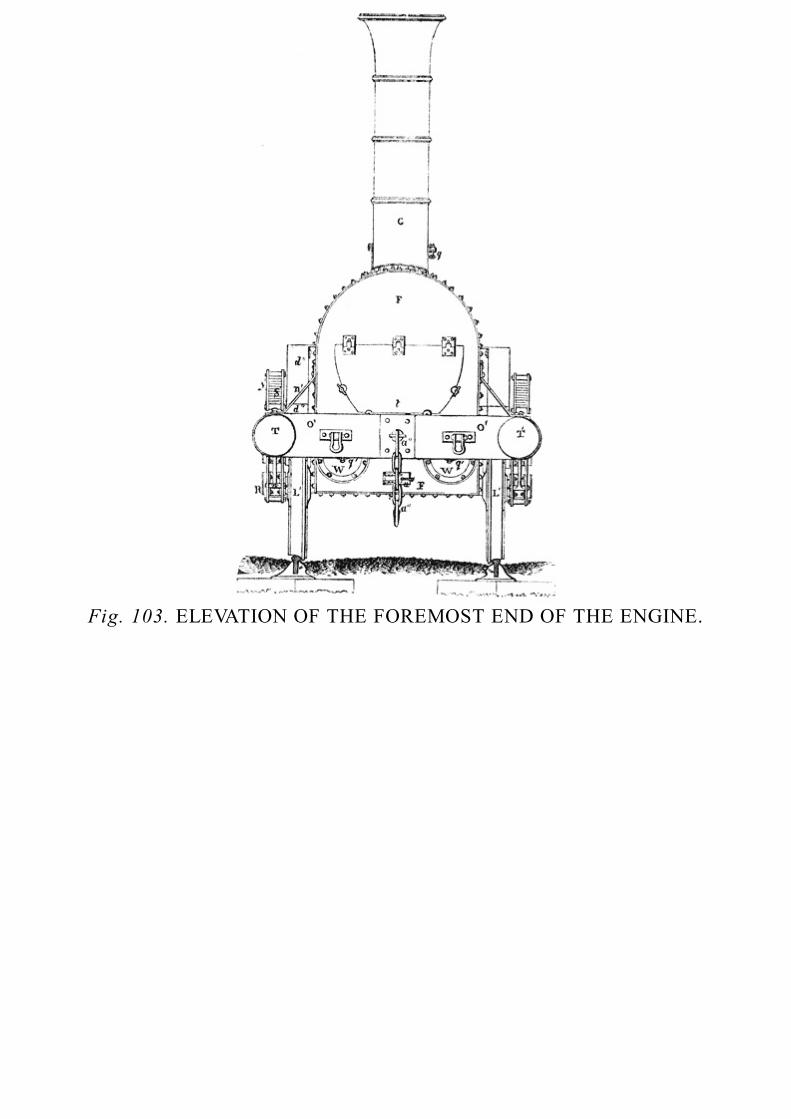
Fig. 103. ELEVATION OF THE FOREMOST END OF THE ENGINE.

Fig. 104. CROSS VERTICAL SECTION OF ENGINE THROUGH THE SMOKE-BOX.
As the top of the internal fire-box cannot be strengthened by stays of this kind, ribs of wrought-iron, which are seen in their length at l, in fig. 97., and of which an end view is seen in fig. 102.,are attached by bolts to it. These ribs are hollowed out, as seen in fig. 97., between bolt and bolt,in order to break their contact with the roof of the fire-box, and allow a more free passage to theheat through it. If they were in continuous contact with the fire-box, the metal composing themwould become more highly heated, and would soon wear out, besides intercepting heat from thewater. This part of the fire-box is subject to rapid wear, unless care be taken that the level of thewater be preserved at its proper height in the boiler. Even when the boiler is properly filled, thedepth of water above the roof of the fire-box is not considerable, and on the least neglect the roofmay be exposed to the contact of steam, in which case it will soon be destroyed.
To prevent accidents arising from this cause, a leaden plug, [Pg368] represented at m, figs. 97. and102., is inserted in the roof of the internal fire-box. If the water be allowed to subside, this plugwill melt out before the copper is very injuriously heated, and the steam rushing out at the aperturewill cause the fire to be extinguished.
Copper fire-boxes are almost universally used; but sometimes, from the consideration ofcheapness, the internal fire-box is constructed of iron.
In the plating which forms the back of the external fire-box, an oval aperture is formed, as
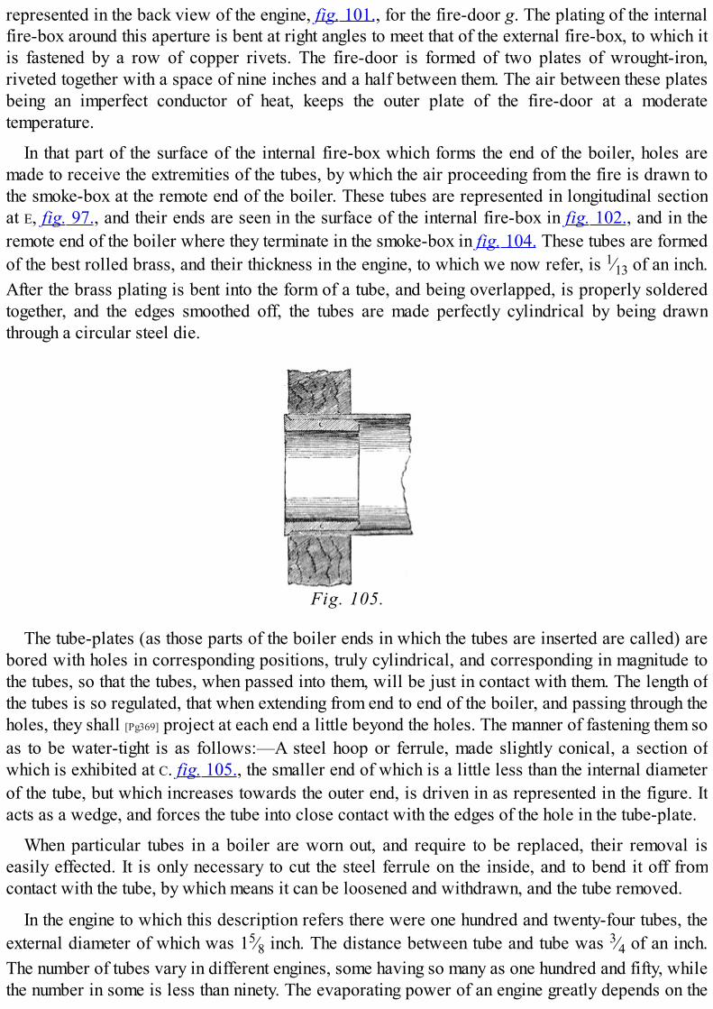
represented in the back view of the engine, fig. 101., for the fire-door g. The plating of the internalfire-box around this aperture is bent at right angles to meet that of the external fire-box, to which itis fastened by a row of copper rivets. The fire-door is formed of two plates of wrought-iron,riveted together with a space of nine inches and a half between them. The air between these platesbeing an imperfect conductor of heat, keeps the outer plate of the fire-door at a moderatetemperature.
In that part of the surface of the internal fire-box which forms the end of the boiler, holes aremade to receive the extremities of the tubes, by which the air proceeding from the fire is drawn tothe smoke-box at the remote end of the boiler. These tubes are represented in longitudinal sectionat E, fig. 97., and their ends are seen in the surface of the internal fire-box in fig. 102., and in theremote end of the boiler where they terminate in the smoke-box in fig. 104. These tubes are formedof the best rolled brass, and their thickness in the engine, to which we now refer, is 1⁄13 of an inch.After the brass plating is bent into the form of a tube, and being overlapped, is properly solderedtogether, and the edges smoothed off, the tubes are made perfectly cylindrical by being drawnthrough a circular steel die.
Fig. 105.
The tube-plates (as those parts of the boiler ends in which the tubes are inserted are called) arebored with holes in corresponding positions, truly cylindrical, and corresponding in magnitude tothe tubes, so that the tubes, when passed into them, will be just in contact with them. The length ofthe tubes is so regulated, that when extending from end to end of the boiler, and passing through theholes, they shall [Pg369] project at each end a little beyond the holes. The manner of fastening them soas to be water-tight is as follows:—A steel hoop or ferrule, made slightly conical, a section ofwhich is exhibited at C. fig. 105., the smaller end of which is a little less than the internal diameterof the tube, but which increases towards the outer end, is driven in as represented in the figure. Itacts as a wedge, and forces the tube into close contact with the edges of the hole in the tube-plate.
When particular tubes in a boiler are worn out, and require to be replaced, their removal iseasily effected. It is only necessary to cut the steel ferrule on the inside, and to bend it off fromcontact with the tube, by which means it can be loosened and withdrawn, and the tube removed.
In the engine to which this description refers there were one hundred and twenty-four tubes, theexternal diameter of which was 15⁄8 inch. The distance between tube and tube was 3⁄4 of an inch.The number of tubes vary in different engines, some having so many as one hundred and fifty, whilethe number in some is less than ninety. The evaporating power of an engine greatly depends on the

proper number and magnitude of its tubes; and the experience which engineers have had onrailways have led them gradually to increase the number of tubes, and diminish their magnitude. Inthe Rocket, already mentioned as having gained the prize on the opening of the Liverpool andManchester Railway, the number of tubes was twenty-four, and their diameter three inches; but inall the engines subsequently made their number was augmented, and their diameter diminished. Thepractical inconvenience which limits the size of the tubes is their liability to become choked bycinders and ashes, which get wedged in them when they are too small, and thereby obstruct thedraft, and diminish the evaporating power of the boiler. The tubes now in use, of about an inch anda [Pg370] half internal diameter, not only require to be cleared of the ashes and cinders, which getfastened in them after each journey, but it is necessary throughout a journey of any length that thetubes should be picked and cleaned by opening the fire door at convenient intervals.
The substitution of brass for copper tubes, which has been already mentioned as so great animprovement in the construction of locomotive engines, is ascribed to Mr. Dixon, who suggestedthem in 1833, being then the resident engineer of the Liverpool and Manchester Railway. They aresaid to last six or eight times as long as copper tubes of the same dimensions.
When tubes fail, they are usually destroyed by the pressure of the water crushing them inwards:the water enters through the rent made in the tube, and flowing upon the fire extinguishes it. When asingle tube thus fails upon a journey, the engine, notwithstanding the accident, may generally bemade to work to the end of its journey by plugging the ends of the broken tube with hard wood; thewater in contact with which will prevent the fire from burning it away.
Tubes of the dimensions here referred to weigh about sixteen pounds, and lose from six to sevenpounds before they are worn out. Their cost is about one pound each.
The tubes act as stays, connecting the ends of the boiler to strengthen them. Besides these, thereare rods of wrought iron extended from end to end of the boiler above the roof of the internal fire-place. These rods are represented at o in their length in fig. 97., and an end view of them is seen infig. 102. The smoke-box F, fig. 97. 104., containing the cylinders, steam-pipe, and blast-pipe, isfour feet wide, and two feet long. It is formed of wrought iron plates, half an inch thick on the sidenext the boiler, and a quarter of an inch elsewhere. The plates are riveted in the same manner asthose of the fire-box already described. From the top of the smoke-box, which, like the fire-box, issemi-cylindrical, as seen in elevation in fig. 103., and in section fig. 104., rises the chimney G,fifteen inches diameter, and formed of 1⁄8 inch iron plates, riveted and bound round by hoops. It isflanged to the top of the [Pg371] smoke-box, as represented in fig. 104. Near the bottom of the smoke-box the working cylinders are placed, side by side, in a horizontal position, with the slide valvesupwards. In the top of the external fire-box a circular aperture is formed fifteen inches in diameter,and upon this aperture is placed the steam-dome T (figs. 97. 101, 102.) two feet high, and attachedaround the circular aperture by a flange and screw secured by nuts. This steam dome is made ofbrass 3⁄8 inch thick. In stationary boilers, where magnitude is not limited, it has been alreadyexplained, that the space allowed for steam is sufficiently large to secure the complete separationof the vapour from the spray which is mixed with it when it issues immediately from the water. Inlocomotive boilers sufficient space cannot be allowed for this, and the separation of the waterfrom the steam is effected by the arrangement here represented. A funnel-shaped tube d′ (figs. 97.102.), with its wide end upwards, rises into the steam-dome, and reaches nearly to the top of it.This funnel bends towards the back of the fire-box, and is attached by a flange and screws to the

great steam-pipe S, which traverses the whole length of the boiler. The steam rising from the boilerfills the steam-dome T, and descends in the funnel-shaped tube d′. The space it has thus to traverseenables the steam to disengage itself almost completely from the priming. The wider part of thegreat steam-pipe a is flanged and screwed at the hinder end to a corresponding aperture in the backplate of the fire-box. This opening is covered by a circular plate, secured by screws, having astuffing-box in its centre, of the same kind as is used for the piston-rods of steam-cylinders.Through this stuffing-box the spindle a″ of the regulator passes, and to its end is attached a winch h′, by which the spindle a″ is capable of being turned. This winch is limited in its play to a quarterof a revolution. The other end of the spindle a″ is attached to a plate e′ seen edgeways in fig. 97.,and the face of which is seen in fig. 102.: this circular plate e is perforated with two aperturessomewhat less than quadrants. That part of the plate, therefore, which remains not pierced formstwo solid pieces somewhat greater than quadrants. This plate is ground so as to move in steam-tight [Pg372] contact with a fixed plate under it, which terminates at the wide end of the conical mouthof the steam-pipe S. This fixed circular plate is likewise pierced with two nearly quadrantalapertures, corresponding with those in the movable plate e′. When the movable plate e′ is turnedround by the winch h′, the apertures in it may be made to correspond with those of the fixedcircular plate on which it moves, in which position the steam-pipe S communicates with the funneld′ by the two quadrantal apertures thus open. If, on the other hand, the winch h′ be moved from thisposition through a quarter revolution, then the quadrantal openings in the movable plate will bebrought over the solid parts of the fixed plate on which it moves, and these solid parts being a littlemore than quadrants, while the openings are a little less, all communication between the steam-pipe S and the funnel d′ will be stopped, for in this case the quadrantal openings in the fixed andmovable plates respectively will be stopped by the solid parts of these plates. It will be evidentthat as the winch h′ of the regulator is moved from the former position to the latter, in everyintermediate position the aperture communicating between the funnel d′ and the steam-pipe S willbe less in magnitude than the complete quadrant. It will in fact be composed of two openingshaving the form of sectors of a circle less than a quadrant, and these sectors may be made of anymagnitude, however small, until the opening is altogether closed.
By such means the admission of steam from the boiler to the steam-pipe S may be regulated bythe winch h′.
The steam being admitted to the steam-pipe passes through it to the front end of the boiler, andthe pipe being enclosed within the boiler the temperature of the steam is maintained. The steam-pipe passing through the tube-plate at the front end of the boiler is carried to a small distance fromthe tube-plate in the same direction, where it is flanged on to a cross horizontal pipe proceeding tothe right and to the left as represented in fig. 104. This cross pipe is itself flanged to two curvedsteam-pipes S (fig. 104.), by which the steam is conducted to the valve-boxes V V. The lower endsof these curved arms are flanged on to the valve-boxes of the two cylinders [Pg373] at the endsnearest to the boiler. The opening of one of these is exhibited in the right hand cylinder in fig. 99.By these pipes the steam is conducted into the valve-boxes or steam-chests, from which it isadmitted by slide-valves to the cylinders to work the pistons in the same manner as has beenalready described in the large stationary engines.
On the upper sides of the cylinders are formed the steam-chests or valve-boxes, which areexhibited at U (figs. 97. 99. 104.). These are made of cast-iron half an inch thick, and are bolted tothe upper side of each cylinder. At the front end they are also secured by bolts to the smoke-box,

and at the hinder end are attached to the tube-plate. These valve-boxes communicate with thepassages m and n fig. 99. leading to the top and bottom of the cylinder: these are called the steam-ports. They also communicate with a passage o leading to the mouth of a curved horizontal pipe p′connecting the front ends of the two cylinders, as seen in figs. 99. 104. These curved pipes unite ina single vertical pipe p, called the blast-pipe, seen in figs. 97. 104.: this vertical pipe becomesgradually small towards the top, and terminates a little above the base of the funnel or chimney G.In the valve-box is placed the slide-valve v to which is attached the spindle l′. This spindle movesthrough a stuffing-box k′, and is worked by gearing, which will be described hereafter. Accordingto the position given to the slide, a communication may be opened between the steam-chest, or thewaste-port, and either end of the cylinders. Thus when the slide is in the position represented infig. 97. the steam-chest communicates with the front end of the cylinder, while the waste-portcommunicates with the hinder end. If, on the other hand, the spindle l′ being pressed forward, movethe slide to its extreme opposite position, the steam-port n would communicate with the waste-porto, while the steam-chest would communicate with the steam-port m, steam would, therefore, beadmitted to the hinder end of the cylinder, while the foremost end would communicate with thewaste-port. It will be perceived that this arrangement is precisely similar to that of the slide-valves already described (133.). The slide-valve is represented on a larger scale in fig. 106.,where A is the hinder steam-port, [Pg374] B the foremost steam-port, and C the waste-port. Thesurfaces D, separating the steam-ports from the waste-ports, are called the bars: they are planedperfectly smooth, so that the surfaces F and G of the slide-valve, also planed perfectly smooth, maymove in steam-tight contact with them. These surfaces are kept in contact by the pressure of thesteam in the steam-chest, by which the slide-valve is always pressed down. In its middle position,as represented by the dotted lines in the figure, both the steam-ports are stopped by the slide-valve,so that at that moment no steam is admitted to either end of the cylinder. On either side of thisintermediate position the slide has an inch and a half play, which is sufficient to open successivelythe two steam-ports.

Fig. 106.
The cylinders are inserted at one end in the plate of the smoke-box, and at the other in the tube-plate of the boiler. They are closed at either end by cast iron covers, nearly an inch thick, flangedon by bolts and screws. In the cover of the cylinder attached to the tube-plate is a stuffing-box, inwhich the piston rod plays. The metallic pistons used in locomotive engines do not differmaterially from those already described, and therefore need not be here particularly noticed. Fromtheir horizontal position they have a tendency to wear unequally in the cylinders, their weightpressing them on one side only; but from their small magnitude this effect is found to beimperceptible in practice. In the engine here described the stroke of the piston is eighteen inches,and this is the most usual length of stroke in locomotive engines. The piston, in its play, comes ateither end within about half an inch of the inner surface of the covers of the cylinders, this spacebeing allowed to prevent collision. In the foremost cover of the cylinder is inserted a cock q′ (fig.97. 99.), by which any water which may collect in the cylinder by condensation or priming may bedischarged. A cock r′ (fig. 97.), communicating with a small tube proceeding from the branches ofthe waste pipe p′ (fig. 104.), is likewise provided to discharge from that pipe any water whichmay be [Pg375] collected in it. After the steam has been admitted to work the piston through the slide-valve, and has been discharged through the waste-port by shifting that valve, it passes through thepipe p′ into the blast-pipe p, from the mouth of which it issues, with great force, up the funnel G.When the motion of the engine is rapid, the steam from the two cylinders proceeds in an almostuninterrupted current from the blast-pipe, and causes a strong draft up the chimney. The heated airwhich passes from the mouths of the tubes into the smoke-box is drawn up by this current, and acorresponding draft is produced in the fire-box.

Fig. 107.
The piston-rods Y terminate in a fork, by which they are attached to cross heads Z, the ends ofwhich are confined by guide-bars A′, in which they are allowed to play backwards and forwardsthrough a space equal to the stroke of the piston. To these cross heads Z, between the prongs of thefork in which the piston terminates, are attached the foremost ends of the connecting rods B′. Theserods are, therefore, driven backwards and forwards by the motion imparted to the cross head Z bythe piston-rods Y. The connecting rods B′ are attached at the hinder ends to two cranks formed uponthe axles C′ of the driving wheels D′. These two cranks are formed upon the axles precisely at rightangles to each other. The left-hand crank is represented in its horizontal position, in fig. 99., andthe right-hand crank is seen in its vertical position. A cranked axle is represented on a larger scalein fig. 107., and the two cranks are seen in a position oblique to the plane of the figure. As thisaxle is the instrument by which the impelling force is conveyed to the load, and as it has to supporta great portion of the weight of the engine, it is constructed with great strength and precision. It ismade all in one [Pg376] piece, and of the best wrought iron called Back Barrow, or scrap iron. In theengine here described its extreme length is six feet and a half, and its diameter is five inches. Atthe centre part A it is cylindrical, and is increased to five inches and a quarter at C, where thecranks are formed. The sides D of the cranks are four inches thick, and the crank pins B, which aretruly cylindrical, are five inches diameter, and three inches in length, the brasses at the extremitiesof the connecting rods which play upon them having a corresponding magnitude. The distance fromthe centre of the crank-pins B to the centre of the axle A must be exactly equal to half the stroke ofthe piston, and is, therefore, in this case precisely nine inches. Upon the parts F, which are seveninches and a half long, the great driving wheels are firmly fastened, so as to be prevented from

turning or shaking upon the axle. The axle projects beyond the wheels at G, where it is reduced tothree inches and an eighth diameter. These projecting parts G are five inches long, having collars atthe outer ends. Brasses are fixed at the outside frame of the engine which rest upon theseprojections G of the axle, and upon these brasses the weight of the engine is supported. The entireaxle is accurately turned in a lathe, and each of the crank-pins B is likewise turned by suspendingthe axle on centres corresponding with the centres of the crank-pins, and made on strong cast ironarms, which are firmly fixed on the ends of the axle, and project beyond the cranks so as to balancethe axle, and enable it to turn round on the centre of the crank-pin. The axle is by such means madeperfectly true, and the cranks are made of exactly the proper length, and precisely at right angles toeach other. The corners of the cranks are champered off, as shown in the figure, and the ends of thecylindrical parts well rounded out.
The strength and accuracy of construction indispensable in these cranked axles, in order to makethem execute their work, render them very expensive. Those which are here described cost about50l. each. When properly constructed, however, they are seldom broken, but are sometimes bentwhen the engine escapes from the rails.
The proper motion to admit and withdraw the steam from [Pg377] either end of the cylinder isimparted to the slide-valves by eccentrics, in a manner and on a principle so similar to that alreadydescribed in large stationary engines, that it will not be necessary here to enter into any detailedexplanation of the apparatus for communicating this motion, which is exhibited in plan and sectionin figs. 97. 99. The eccentrics are attached to the cranked axles at E′ E″. The eccentric E′ impartsmotion by a rod e″ to a lever h″, formed on an axle extending across the frame of the engine. Thisconveys motion to another lever l″, projecting from the same axle. This lever l″ is jointed tohorizontal links m″, which at the foremost ends are attached to the spindle l′, by which the slide isdriven. By these means the motion received by the eccentric from the great working axle conveysto the spindle l′ an alternate movement backwards and forwards, and the points at which it isreversed will be regulated by the position given to the eccentric upon the great axle. The eccentricis formed in two separate semicircles, and is keyed on to the great axle, and consequently anyposition may be given to it which may be required. The position to be given to the eccentricsshould be such that they shall be at right angles to their respective cranks, and they should be fixeda quarter of a revolution behind the cranks so as to move the slides to that extent in advance of thepistons, since by the position of the levers h″ and l″, the motion of the eccentric becomes reversedbefore it reaches the valve spindle.
The performance of the engine is materially affected by the position of the eccentrics on theworking axle. The slide should begin to uncover the steam-port a little before the commencementof the stroke of the piston, in order that the steam impelling the piston should be shut off, and thesteam about to impel it in the contrary direction admitted before the termination of the stroke.Through this small space the steam, therefore, must act in opposition to the motion of the piston.This is called the lead of the slide, and the extent generally given to it is about a quarter of an inch.This is accomplished by fixing the eccentrics not precisely at right angles to the respective cranks,but a little in advance of that position. The introduction of the steam to [Pg378] the piston before thetermination of the stroke has the effect of bringing it gradually to rest at the end of the stroke, andthereby diminishing the jerk or shock produced by the rapid change of motion. In stationaryengines, where the reciprocations of the engine are slow, the necessity for this provision does notarise; but in locomotive engines in which the motion of the piston is changed from four to six times

in a second, it becomes necessary. The steam admitted to the piston before the termination of thestroke acts as a spring-cushion to assist in changing its motion, and if it were not applied, thepiston could not be kept tight upon the piston-rod. Another advantage which is produced byallowing some lead to the slide is that the waste steam which has just impelled the piston begins tomake its escape through the waste-port before the commencement of the next stroke, so that whenthe impelling steam begins to produce the returning stroke, there is less waste steam on the otherside of the piston to resist it.
When the motion of the engine is very rapid, the resistance of the waste steam, as it escapesfrom the blast-pipe to the piston, has been generally supposed to be very considerable, though weare not aware of any direct experiments by which its amount has been ascertained. In the accountof the locomotive engine which has been here described, supplied by Mr. Stephenson for the lastedition of Tredgold on the Steam Engine, he states, that the average resisting pressure of the wastesteam throughout the stroke is 6 lbs. per square inch, when running at the usual rate of from 25 to28 miles an hour, and that at greater velocities this negative pressure has been found to increase tomore than double that amount. No experiments are, however, cited from which this inference hasbeen drawn.
It has been also thought that the pressure of steam upon the piston in the cylinder, at highvelocities, is considerably below the pressure of steam in the boiler; but this has not been, so faras we are informed, ascertained by any satisfactory experimental test. Mr. Stephenson likewisestates, that this loss of pressure, causes the negative pressure or resistance of the waste steam toamount to [Pg379] from 30 to 40 per cent. of the positive pressure upon the piston when the engine isrunning very fast, and that therefore the power of the engine is diminished nearly one half.
But it will be perceived that besides the uncertainty which attends the estimate of the actualamount of pressure on the piston compared with the pressure of steam in the boiler, the inferencehere drawn does not appear to be compatible with what has been already proved respecting themechanical effect of steam. No change of pressure which may take place between the boiler andthe cylinder can affect the practical efficacy of the steam. As the steam passes through the engine,whatever change of pressure it may be subject to, it still remains common steam; and though itspressure may be diminished, its volume being increased in a nearly equal proportion, itsmechanical effect will remain the same. The power of the engine, therefore, estimated as it ought tobe, by the whole mechanical effect produced, will not be altered otherwise than by the effect of theincreased resistance produced by the blast-pipe. What that resistance is, we repeat, has not, so faras we know, been ascertained by direct experiment, and there are circumstances attending it whichrender it probable that, even at high velocities, it is less in amount than Mr. Stephenson's estimate.
The position of the eccentrics which is necessary to make the pistons drive the engine forwardmust be directly the reverse of that which would cause them to drive the engine backwards. To beable, therefore, to reverse the motion of the engine, it would only be necessary to be able toreverse the position of the eccentrics, which may be accomplished by either of two expedients.
First, The eccentrics may be capable of revolving on the great working axle, and also of slidingupon it through a small space. Their revolution on the axle may be checked by letting a pinattached to a collar fastened on the axle fall into a hole on the side of the eccentric. Such a pinwill drive the eccentric round with the axle, and the position of this pin and the hole willdetermine the position of the eccentric with reference to the crank. At a short distance [Pg380] on

the other side of the eccentric may be a corresponding collar with a pin in the opposite position.By moving the eccentric longitudinally on the axle, the former pin may be withdrawn from thehole, and the latter allowed to fall into the hole on the other side. Proper mechanism may beprovided by which the position of the eccentric may thus be reversed in reference to the crank,and by such means the motion of the engine may be reversed.Secondly, Supposing the eccentrics which drive the engine forward to be immovably fixed uponthe axle, two other eccentrics may be provided attached to other parts of the same axle, andhaving a position exactly the reverse with reference to the cranks. Proper mechanism may beprovided, by which either or both pairs of eccentrics may be thrown in or out of gear. Such arethe means adopted in the engine which has been already described. The eccentrics for drivingthe engine backwards are placed outside the cranks at F′ F″. A hand lever w″ fig. 101. isprovided, by which the engine man may throw either pair of eccentrics into or out of gear, so asto make the engine work either backwards or forwards.
Figs. 108., 109., 110.
As all the moving parts of the engine require to be constantly lubricated with oil to diminish thefriction, and keep them cool, oil-cups for this purpose are fixed upon them. In some engines theseoil-cups are attached separately to all the moving parts: in others they are placed near each otherin a row on the boiler, and communicate by small tubes with the several parts required to belubricated. One of these is requisite for each end of the connecting rods, for each of the guides ofthe piston-rods, for the piston-rod itself, the spindle of the slide-valve, and other parts. Anelevation of one of these oil-cups is shown in fig. 108., a vertical section in fig. 109., andhorizontal plan in fig. 110. The cup A is made of brass with a cover B. This cover has a pieceprojecting from it turning upon a pin in a socket C at the side of the cup A, and square at the end,resting upon a small spring at the bottom of the socket to hold it either open or shut. In the bottomof the [Pg381] cup is inserted an iron tube D extending nearly to the top. This tube projects from thebottom of the cup, where it is tapped for the purpose of fixing the cup on the part of the enginewhich it is intended to lubricate. The hole into which the cup is screwed communicates with therubbing surface, and some cotton thread is passed through the tube dipping into the oil in the cup atthe one end and touching the moving part at the other. This thread acts as a siphon, and constantlydrops oil on the rubbing surface.
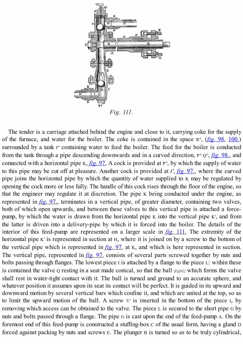
Fig. 111.
The tender is a carriage attached behind the engine and close to it, carrying coke for the supplyof the furnace, and water for the boiler. The coke is contained in the space R″, (fig. 98. 100.)surrounded by a tank I″ containing water to feed the boiler. The feed for the boiler is conductedfrom the tank through a pipe descending downwards and in a curved direction, P″ Q″, fig. 98., andconnected with a horizontal pipe K, fig. 97. A cock is provided at P″, by which the supply of waterto this pipe may be cut off at pleasure. Another cock is provided at t′, fig. 97., where the curvedpipe joins the horizontal pipe by which the quantity of water supplied to K may be regulated byopening the cock more or less fully. The handle of this cock rises through the floor of the engine, sothat the engineer may regulate it at discretion. The pipe K being conducted under the engine, asrepresented in fig. 97., terminates in a vertical pipe, of greater diameter, containing two valves,both of which open upwards, and between these valves to this vertical pipe is attached a force-pump, by which the water is drawn from the horizontal pipe K into the vertical pipe K′, and fromthe latter is driven into a delivery-pipe by which it is forced into the boiler. The details of theinterior of this feed-pump are represented on a larger scale in fig. 111. The extremity of thehorizontal pipe K′ is represented in section at H, where it is joined on by a screw to the bottom ofthe vertical pipe which is represented in fig. 97. at K, and which is here represented in section.The vertical pipe, represented in fig. 97. consists of several parts screwed together by nuts andbolts passing through flanges. The lowest piece I is attached by a flange to the piece L: within theseis contained the valve Q resting in a seat made conical, so that the ball [Pg382] which forms the valveshall rest in water-tight contact with it. The ball is turned and ground to an accurate sphere, andwhatever position it assumes upon its seat its contact will be perfect. It is guided in its upward anddownward motion by several vertical bars which confine it, and which are united at the top, so asto limit the upward motion of the ball. A screw V′ is inserted in the bottom of the piece I, byremoving which access can be obtained to the valve. The piece L is secured to the short pipe G bynuts and bolts passed through a flange. The pipe G is cast upon the end of the feed-pump A. On theforemost end of this feed-pump is constructed a stuffing-box C of the usual form, having a gland D
forced against packing by nuts and screws E. The plunger B is turned so as to be truly cylindrical,

and moves in water-tight contact through the gland D. The plunger not being in contact with theinner surface of the pump-barrel A, the latter need not be ground. The horizontal rod by which theplunger B is driven is attached at its foremost extremity to an arm which projects from the rod ofthe steam-piston, and consequently this plunger is moved through a space equal to the stroke of thesteam-piston. In this case that space is eighteen inches. The [Pg383] upper end of the vertical tube G isattached by screws and a flange to a piece P containing a valve R similar in all respects to thelower valve Q, and like it opening upwards. A screw V is introduced at the top by which accessmay be obtained to this valve. This screw also presses on the crown of the guides of the valve, soas to hold it down by regulated pressure. At the side of this upper piece P is inserted a horizontaltube M connected with the end of the delivery-pipe N. This latter is continued to the boiler withwhich it communicates at the fire-box. When the plunger B is drawn out of the pump-barrel A, thespherical valve Q being relieved from its downward pressure is raised, and water passes from thepipe H through the valve Q into the vertical pipe G; the lower valve Q then closes and stops thereturn of the water. The plunger B returning into the pump-barrel A then forces the water against theupper valve R and drives it through the delivery-tube N, from which its return is prevented by thevalve R. When the delivery-tube N is filled with water throughout its whole length, every stroke ofthe plunger will evidently drive into the boiler a volume of water equal to the magnitude of a partof the plunger eighteen inches in length.
Until within the last few years, locomotive engines were supported on only four wheels; theyare, however, now almost universally supported on six, the driving wheels being in the middle. Togive greater security to the position of the engine between the rails it is usual to construct flangeson the tires of all the six wheels. Mr. Stephenson, however, has been in the practice of constructingthe driving wheels without flanges, and with tires truly cylindrical, depending on the flanges of thetwo pairs of smaller wheels to maintain the engine between the rails. The wheels of the enginehere described are constructed in this manner. The driving wheels D′ are fixed on the cranked axleC′, and are five feet in diameter. The other wheels L′ M′, the one being placed immediately behindthe smoke-box, and the other immediately behind the fire-box, are each three feet six inches indiameter, and have a flange upon their tires, which running on the [Pg384] inside of each rail keepsthe engine between the rails. Each pair of these small wheels, like the driving-wheels, is fixedupon their axle. The axles are 35⁄8 inches diameter, and project beyond the wheels, the projectingpart supporting the frame of the engine and turning in brasses. Upon these brasses rest springs,which bear the whole weight of the engine. These springs having nothing between them and theroad but the wheels and axles intercept and equalise the sudden shocks produced by the rapidmotion upon the road.
When an engine is required for the transport of very heavy loads, such as those of merchandise,the adhesion of one pair of working wheels is found to be insufficient, and, in such cases, one ofthe two pairs of wheels L′ M′ is made of the same diameter as the wheels which are placed upon theworking axle, and a bar is attached to points on the outside of the wheels at equal distances fromtheir centre, connecting them in such a manner that any force applied to make one pair of wheelsrevolve must necessarily impart the same motion to the other pair. By such means the force of thesteam is made to drive both pairs of wheels, and consequently a proportionally increased adhesionis obtained.
The velocity which an engine is capable of imparting to the load which it draws depends upon

the rate at which the pistons are capable of being moved in the cylinders. By every motion of eachpiston backwards and forwards one revolution of the driving wheels is produced, and by eachrevolution of the driving wheels, supposing them not to slip upon the rails, the load is driventhrough a distance upon the road equal to their circumference. As the two cylinders work together,it follows, that a quantity of steam sufficient to fill four cylinders supplied by the boiler to theengine will move the train through a distance equal to the circumference of the driving wheels; andin accomplishing this, each piston must move twice from end to end of the cylinder; each cylindermust be twice filled with steam from the boiler; and that steam must be twice discharged from thecylinder through the blast-pipe into the chimney.
[Pg401] If the driving wheels be five feet in diameter their circumference will be fifteen feet seveninches. To drive a train with a velocity of thirty miles an hour, it will be necessary that the engineshould be propelled through a space of forty-five feet per second. To accomplish this with five-feet wheels they must be therefore made to revolve at the rate of very nearly three revolutions persecond; and as each revolution requires two motions of the piston in the cylinder, it follows thateach piston must move three times forwards and three times backwards in the cylinder in a second;that steam must be admitted six times per second from the steam-chest to each cylinder, anddischarged six times per second from each cylinder into the blast-pipe. The motion, therefore, ofeach piston, supposing it to be uniform, must divide a second into six equal parts, and the puffs ofthe blast-pipe in the chimney must divide a second into twelve equal parts. The motion of theslides and other reciprocating parts of the machinery must consequently correspond.
This motion of the reciprocating parts of the machinery being found to be injurious to it, and toproduce very rapid wear, attempts have been made to remedy the defect, and to obtain greaterspeed with an equal or diminished rate of motion of the piston, by the adoption of driving wheelsof greater diameter, and on several of the great lines of railway the magnitude of the wheels for thepassenger-engines have been increased to five feet and a half and six feet diameter; but suchengines have not been sufficiently long in use to afford grounds for forming a practical estimate oftheir effects. Experiments of a much bolder description have, however, been tried on one of thegreat lines of railway by the adoption of driving wheels of much greater diameter. In some casestheir magnitude has been increased even to ten feet; but from various experiments to which theseengines have been submitted by myself and others, as well as from the experience which appearsto be obtained from the results of their ordinary work, it does not appear that any advantages haveattended them, and they have been accordingly for the most part abandoned.
The pressure of steam in the boiler is limited by two safety-valves, [Pg402] represented in fig. 97.at N and O. The valve at N is under the control of the engineer, but the valve at O is inaccessible tohim. The structure of the safety-vale represented at N is exhibited on a larger scale in fig. 112.,which represents its section, and fig. 113., which shows a plan of the valve-seat with the valveremoved. The valve A, which is made of brass, is mitred round the edge at an angle of 45°, and hasa spindle, or stalk B, cast upon it, projecting downwards from the middle of it. The valve-seat C isalso made of brass, and cast with a flange at the bottom to attach it to the boiler. The mitred surfaceof the valve is ground into the valve-seat, so as to rest in steam-tight contact with it. Across thevalve-seat, which is two and a half inches in diameter, is cast a thin piece D, seen in plan in fig.113. and in section in fig. 112. which extends from the top to the bottom, and has a longitudinalhole through it, in which the spindle B of the valve works: by this hole it is guided when it risesfrom its seat. A projection E is cast upon the seat of the valve, in which a standard F is inserted.

This standard is forked at the top, and receives the end of a lever G, which turns in it upon a centre.A rod H is jointed to this lever by another pin at three inches from the former, and the lower end ofthis rod, ground to a point, presses upon the centre of the valve A. At the other end of the lever,which is broken off in fig. 112., at a distance of three feet from the centre pin, inserted in the forkof the pillar F, the rod of a common spring-balance w, fig. 101., is attached by a finger-nut n. Thebottom of this spring-balance is secured on to the fire-box. This balance is screwed up by thefinger-nut on the valve-lever until the required pressure on the lever is produced through themedium of the rod H, this pressure being generally fifty pounds per square inch above theatmosphere. When the pressure of the steam in the boiler exceeds this, the valve A is raised fromits seat, and the steam escapes.
Figs. 112., 113.
It is evident that the sliding weight by which the pressure [Pg403] of the safety-valve is sometimesregulated in stationary engines would not be admissible in a locomotive engine, since the motionof the engine would constantly jolt it up and down, and cause the steam to escape. One of thedisadvantages attending the use of the spring-valve is that it cannot be opened to let the steamescape without increasing its force, so that the steam, when escaping, must really have a greaterpressure than that to which the valve has been previously adjusted. The longer the lever is, thegreater will be this difference of pressure, inasmuch as a given elevation of the pin governing therod H would cause a proportionally greater motion in that end of the lever attached to the spring.
The second safety-valve O is enclosed in a case, so that it is inaccessible, and its purpose is tolimit the power of the engineer to increase the pressure of steam in the boiler. This valve is similarin construction to the former, but instead of being held down by a lever, is pressed upon by severalsmall elliptical springs placed one above another over the valve, and held down by a screw whichturns in a frame Y, fixed into the valve-seat. By this screw the pressure on the valve can beadjusted to any required degree; and if the open safety-valve be screwed down to a greaterpressure, the steam will begin to escape from this second valve.
Also in the case where the boiler produces surplus steam faster than its escape can be effectedat the valve N, the pressure will sometimes be increased until the valve O is opened, and its escapewill take place from both valves.
The whole weight of the engine bears upon those parts of the six axles R′, fig. 99., which projectbeyond the wheels. Boxes are formed in which these parts of the axles turn, and through themedium of which the weight of the engine rests upon them. Over these boxes are constructed oil orgrease cups, by means of which the axles are constantly lubricated. It is usual to lubricate the axlesof the engine itself with oil: the axles of the tender, and other coaches and waggons, are lubricatedwith a mixture of oil and tallow. In the middle of the box in which the axle turns, and between the

two oil-cups, is cast a socket, in which the end of the spindle on [Pg404] which the spring pressesrests. The springs are composed of a number of steel-plates, laid, in the usual manner, one abovethe other, increasing in length upwards. In the engine here described, the plates forming the springsof the driving wheels are thirteen in number, each of which is four inches in width, and 5⁄16ths of aninch in thickness. The springs upon the other wheels are three inches in width. The springs of thedriving wheels are below the axle, while those of the smaller wheels are above it.
Buffers D″ are placed behind the tender, which act upon a spring C (fig. 100.), to break thecollision, when the waggons or carriages strike upon the tender, and similar buffers are attached toall passenger-coaches. Some of these buffers are constructed with a system of springs similar to C,but more elastic, and combined in greater number under the framing of the carriage, so that aconsiderable play is allowed to them. In some cases the rods of the buffers are made to act uponstrong spiral springs inserted in the sides of the framing of the carriage. This arrangement givesgreater play to the buffers; and as every coach in a train has several buffers, the combined effect ofthese is such, that a considerable shock given to either end of the train may be rendered harmlessby being spent upon the elasticity of these several systems of springs.
In order to give notice of the approach of a train, a steam-whistle Z′, fig. 97. fig. 101., is placedimmediately above the fire-box at the back of the engine. This is an apparatus composed of twosmall hemispheres of brass, separated one from the other by a small space. Steam is made to passthrough a hollow space constructed in the lower hemisphere, and escapes from a very narrowcircular opening round the edge of that hemisphere, rushing up with a force proportionate to itspressure. The edge of the upper hemisphere presented downwards encounters this steam, and aneffect is produced similar to the action of air in organ pipes. A shrill whistle is produced, whichcan be heard at a very considerable distance, and, differing from all ordinary sounds, it never failsto give timely notice of the approach of a train.
The water tank I″, fig. 98. 100., which is constructed on the tender, is formed of wrought-ironplates 1⁄8 of an inch thick, [Pg405] riveted at the corners by angle iron already described. This tank is9 feet long, 63⁄4 feet wide, and 21⁄4 feet deep. The top is covered with a board K″, and a raisedplatform N″ is constructed behind, divided into three parts, covered with leads, which open onhinges. The middle lid covers an opening to the tank by which water is let in: the lids at either sidecover boxes in which are contained the tools necessary to be carried with the engine. The curvedpipe P″, fig. 98., leading from the bottom of the tank to the pipe Q″, is of copper. The pipe Q″,connecting the latter with the feed-pipe K′, fig. 99., is sometimes formed of leather or India-rubbercloth, having a spiral spring on the inside to prevent it from collapsing. It is necessary that thispipe Q″ should have a power of yielding to a sufficient degree to accommodate itself to theinequalities of motion between the engine and tender. A metal pipe is sometimes used, suppliedwith a double ball and socket, and a telescopic joint, having sufficient play to allow for the lateraland longitudinal inequalities of motion of the engine and tender. The weight of an engine, such asthat here described, supplied with its proper quantity of water and fuel, is about 12 tons: thetender, when empty, weighs about 31⁄4 tons; and when filled with water and fuel its weight is 7tons. The tank contains 700 gallons of water, and the tender is capable of carrying about 800weight of coke. This supply is sufficient for a trip of from thirty to forty miles with an ordinaryload.

(198.) It is not usual to express the power of locomotive engines in the same manner as that ofother engines by the term horse-power. Indeed, until the actual amount of resistance opposed tothese machines, under the various circumstances in which they are worked, shall be ascertainedwith some degree of precision, it is impossible that their power or efficiency can be estimatedwith any tolerable degree of approximation. The quantity of water evaporated, and passed in steamthrough the cylinders, supplies a major limit to the power exerted; but even this necessary elementfor the calculation of the efficacy of these machines has not been ascertained by a sufficientlyextensive course of observation and experiment. Mr. Stephenson states, that the engine which [Pg406]
has been here described is capable of evaporating 77 cubic feet of water per hour, while the earlylocomotives could only evaporate 16 cubic feet per hour. This evaporation, however, is inferior tothat which I have ascertained myself to be produced by engines in regular operation on some of thenorthern railways. In an experiment made in July, 1839, with the Hecla engine, I found that theevaporation in a trip of ninety-five miles, from Liverpool to Birmingham, was at the rate of 93·2cubic feet per hour, and in returning the same distance it was at the rate of 85·7 cubic feet per hour,giving a mean of 89 cubic feet per hour nearly. The Hecla weighed 12 tons; and its dimensions andproportions corresponded very nearly with those of the engine above described.
In a course of experiments which I made upon the engines then in use on the Grand JunctionRailway in the autumn of 1838 I found that the ordinary evaporating power of these engines variedfrom eighty to eighty-five cubic feet per hour.
Engines of much greater dimensions, and consequently of greater evaporating power, are usedon the Great Western Railway. In the autumn of 1838 experiments were made upon these enginesby Mr. Nicholas Wood and myself, when we found that the most powerful engine on that line, theNorth Star, drawing a load of 1101⁄2 tons gross, engine and tender inclusive, at 301⁄2 miles an hour,evaporated 200 cubic feet of water per hour. The same engine drawing a load of 1941⁄2 tons at181⁄2 miles an hour evaporated 141 cubic feet per hour, and when drawing 45 tons at 381⁄2 miles anhour evaporated 198 cubic feet of water per hour.
It has been already shown that a cubic foot of water evaporated per hour produces a grossamount of mechanical force very little less than two-horse power, and consequently the grossamount of mechanical power evolved in these cases by the evaporation of the locomotive boilerswill be very nearly twice as many horse-power as there are cubic feet of water evaporated perhour. Thus the evaporation of the Hecla, in the experiments made in July, 1839, gave a gross powerof about one hundred and eighty horses, while the evaporation of the North Star gave a power ofabout four hundred horses. In stationary engines about half the gross [Pg407] power evolved in theevaporation is allowed for waste, friction, and other sources of resistance not connected with theload. What quantity should be allowed for this in locomotive engines is not yet ascertained, andtherefore it is impossible to state what proportion of the whole evaporation is to be taken asrepresenting the useful horse-power.
(199.) The great uniformity of resistance produced by the traction of carriages upon a railway issuch as to render the application of steam power to that purpose extremely advantageous. So far asthis resistance depends on mechanical defects, it is probably rendered as uniform as is practicable,and in proportion to the quantity of load carried is reduced to as small an amount as it is likely toattain under any practicable circumstances. Until a recent period this resistance was ascribedaltogether, or nearly so, to mechanical causes. The inequalities of the road-surface, the friction of

the axles of the wheels in their bearings, and the various sources of resistance due to the machineryof the engine, being the principal of these resistances, were for the most part independent of thespeed with which the train was moved; and it was accordingly assumed in all calculationsrespecting the power of locomotive engines that the resistance would be practically the samewhatever might be the speed of the train. It had been well understood that so far as the atmospheremight offer resistance to the moving power this would be dependent on the speed, and wouldincrease in a very high ratio with the speed; but it was considered that the part of the resistancedue to this cause formed a fraction of the whole amount so insignificant that it might be fairlydisregarded in practice, or considered as a part of the actual computed resistance taken at anaverage speed.
It has been, until a late period, accordingly assumed that the total amount of resistance torailway trains which the locomotive engines have had to overcome was about the two hundred andfiftieth part of the gross weight of the load drawn: some engineers estimated it at a two hundredand twentieth; others at a two hundred and fiftieth; others at a three hundred and thirtieth part of theload; and the two hundred and fiftieth part of the gross load drawn may perhaps be [Pg408]
considered as a mean between these much varying estimates. What the experiments were, if any, onwhich these rough estimates were based, has never appeared. Each engineer formed his ownvaluation of this effect, but none produced the experimental grounds of their opinion. It has beensaid that the trains run down the engine, or that the drawing chains connecting the engine slacken indescending an inclination of sixteen feet in a mile, or 1⁄330. Numerous experiments, however, madeby myself, as well as the constant experience now daily obtained on railways, show that this is afallacious opinion, except at velocities so low as are never practised on railways.

(200.) In the autumn of 1838 a course of experiments was commenced at the suggestion of someof the proprietors of the Great Western Railway Company, with a view to determine various pointsconnected with the structure and the working of railways. A part of these experiments wereintended to determine the mean amount of the resisting force opposed to the moving power, andthis part was conducted by me. After having tried various expedients for determining the meanamount of resistance to the moving power, I found that no method gave satisfactory results exceptone founded on observing the motion of trains by gravity down steep inclined planes. When a trainof waggons or coaches is placed upon an inclined plane so steep that it shall descend by its gravitywithout any moving power, its motion, when it proceeds from a state of rest, will be graduallyaccelerated, and if the resistance to that motion was, as it has been commonly supposed to be,uniform and independent of the speed, the descent would be uniformly accelerated: in other words,the increase of speed would be proportional to the time of the motion. Whatever velocity the trainwould gain in the first minute, it would acquire twice that velocity at the end of the second minute,three times that velocity at the end of the third minute, and so on; and this increase of velocitywould continue to follow the same law, however extended the plane might be. That such would bethe law which the descending motion of a train would follow had always been supposed, up to thetime of the experiments now referred to; and it was even maintained by some that [Pg409] such a lawwas in strict conformity with experiments made upon railways and duly reported. The firstexperiments instituted by me at the time just referred to afforded a complete refutation of thisdoctrine. It was found that the acceleration was not uniform, but that with every increase of speedthe acceleration was lessened. Thus if a certain speed were gained by a train in one second whenmoving at five miles an hour, a much less speed was gained in one second when moving ten milesan hour, and a comparatively small speed was gained in the same time when moving at fifteenmiles an hour, and so on. In fact, the augmentation of the rate of acceleration appeared to diminishin a very rapid proportion as the speed increased: this suggested to me the probability that asufficiently great increase of speed would destroy all acceleration, and that the train would atlength move at a uniform velocity. In effect, since the moving power which impels a train down aninclined plane of uniform inclination is that fraction of the gross weight of the train which acts inthe direction of the plane, this moving power must be necessarily invariable; and as anyacceleration which is produced must arise from the excess of this moving power over theresistance opposed to the motion of the train, from whatever causes that resistance may arise,whenever acceleration ceases, the moving force must necessarily be equal to the resistance; andtherefore, when a train descends an inclined plane with a uniform velocity, the gross resistance tothe motion of the train must be equal to the gross weight of the train resolved in the direction of theplane; or, in other words, it must be equal to that fraction of the whole weight of the train which isexpressed by the inclination of the plane. Thus if it be supposed that the plane falls at the rate ofone foot in one hundred, then the force impelling the train downwards will be equal to thehundredth part of the weight of the train. So long as the resistance to the motion of the traincontinues to be less than the hundredth part of its weight, so long will the motion of the train beaccelerated; and the more the hundredth part of the weight exceeds the resistance, the more rapidwill the acceleration be; and the less the hundredth part of the weight [Pg410] exceeds the resistance,the less rapid will the acceleration be. If it be true that the amount of resistance increases with theincrease of speed, then a speed may at length be attained so great that the amount of resistance tothe motion of the train will be equal to the hundredth part of the weight. When that happens, themoving power of a hundredth part of the weight of the train being exactly equal to the resistance tothe motion, there is no excess of power to produce acceleration, and therefore the motion of the

train will be uniform.
Founded on these principles, a vast number of experiments were made on planes of differentinclinations, and with loads of various magnitudes; and it was found, in general, that when a traindescended an inclined plane, the rate of acceleration gradually diminished, and at length becameuniform; that the uniform speed thus attained depended on the weight, form, and magnitude of thetrain and the inclination of the plane; that the same train on different inclined planes attaineddifferent uniform speeds—on the steeper planes a greater speed being attained. From suchexperiments it followed, contrary to all that had been previously supposed, that the amount ofresistance to railway trains had a dependence on the speed; that this dependence was of greatpractical importance, the resistance being subject to very considerable variation at differentspeeds, and that this source of resistance arises from the atmosphere which the train encounters.This was rendered obvious by the different amount of resistance to the motion of a train of coachesand to that of a train of low waggons of equal weight.
The former editions of this work having been published before the discovery which has resultedfrom these experiments, the average amount of resistance to railway trains, there stated, and theconclusions deduced therefrom, were in conformity with what was then known. It was stated thatthe resistance to the moving power was practically independent of the speed, and on level railswas at the average rate of about seven pounds and a half per ton. This amount would be equivalentto the gravitation of a load down an inclined plane falling 1⁄300, and consequently in ascending sucha plane the moving power would have to encounter twice [Pg411] the resistance opposed to it on alevel. As it was generally assumed that a locomotive-engine could not advantageously vary itstractive power beyond this limit, it was therefore inferred that gradients (as inclinations arecalled) ought not to be constructed of greater steepness than 1⁄300. It was supposed that indescending gradients more steep than this the train would be accelerated and would require the useof the brake to check its motion, while in ascending such planes the engine would be required toexert more than twice the ordinary tractive power required on level rails. As the resistanceproduced by the air was not taken into consideration, no distinction was made between heavytrains of goods presenting a frontage and magnitude bearing a small proportion to their grossweight and lighter trains of passenger-coaches presenting great frontage and great magnitude inproportion to their weight. The result of the experiments above explained leads to inferencesaltogether at variance with those which have been given in former editions of the present work,and which were then universally admitted by railway engineers. The tendency of the results ofthese experiments show that low gradients on railways are not attended with the advantageouseffects which have been hitherto ascribed to them; that, on the contrary, the resistance produced bysteeper gradients can be compensated by slackening the speed, so that the power shall be relievedfrom as much atmospheric resistance by the diminution of velocity as is equal to the increasedresistance produced by the gravity of the plane which is ascended. And, on the other hand, indescending the plane the speed may be increased until the resistance produced by the atmosphereis increased to the same amount as that by which the train is relieved of resistance by the declivitydown which it moves. Thus, on gradients, the inclination of which is confined within practicallimits, the resistance to the moving-power may be preserved uniform, or nearly so, by varying thevelocity.
(201.) The series of experiments which have established these general conclusions have not yetbeen sufficiently extended and varied to supply a correct practical estimate of the limit which it

would be most advantageous to impose upon the [Pg412] gradients of railways; but it is certain thatrailways may be laid down, without practical disadvantage, with gradients considerably steeperthan those to which it has been hitherto the practice to recommend as a limit.
The principle of compensation by varied speed being admitted, it will follow that the time oftransit between terminus and terminus of a line of railway laid down with gradients, varying fromtwenty to thirty feet a mile, will be practically the same as it would be on a line of the same lengthconstructed upon a dead level; and not only will the time of transport be equal, but the quantity ofmoving power expended will not be materially different. The difference between thecircumstances of the transport in the two cases will be merely that, on the undulating line, avarying velocity will be imparted to the train and a varying resistance opposed to the movingpower; while on the level line the train would be moved at a uniform speed, and the engineworked against a uniform resistance. These conclusions have been abundantly confirmed by theexperiments made in last July with the Hecla engine above referred to. The line of railwaybetween Liverpool and Birmingham on which the experiment was made extended over a distanceof ninety-five miles, and the gradients on which the effects were observed varied from a level tothirty feet per mile, a great portion of the line being a dead level. The following table shows theuniform speed with which the train ascended and descended the several gradients, and also themean of the ascent and descent in each case, as well as the speed upon the level parts of the line:—
Gradient.One in
Speed. Mean.
Ascending.Miles per hour.
Descending.Miles per hour.
177 22·25 41·32 31·78265 24·87 39·13 32·00330 25·26 37·07 31·16400 26·87 36·75 31·81532 27·35 34·30 30·82590 27·37 33·16 30·21650 29·03 32·58 30·80
Level 30·93
[Pg413] From this table it is apparent that the gradients do possess the compensating power withrespect to speed already mentioned. The discrepancies existing among the mean values of thespeed are only what may be fairly ascribed to casual variations in the moving power. Theexperiment was made under favourable circumstances: little disturbance was produced from theatmosphere; the day was quite calm. In the same experiment it was found that the water evaporatedvaried very nearly in proportion to the varying resistance, and the amount of that evaporation maybe taken as affording an approximation to the mean amount of resistance. Taking the trip to andfrom Birmingham over the distance of 190 miles, the mean evaporation per mile was 3·36 cubicfeet of water. The volume of steam produced by this quantity of water will be determinedapproximately by calculating the number of revolutions of the driving wheels necessary to movethe engine one mile. The driving wheels being 5 feet in diameter, their circumference was 15·7feet, and consequently in passing over a mile they would have revolved 336·3 times. Since eachrevolution consumes four cylinders full of steam, the quantity of steam supplied by the boiler to thecylinders per mile will be found by multiplying the contents of the cylinder by four times 336·3, or1345·2.

The cylinders of the Hecla were 121⁄2 inches diameter, and 18 inches in length, and consequentlytheir contents were 1·28 cubic feet for each cylinder: this being multiplied by 1345·2 gives1721·86 or 1722 cubic feet of steam per mile. It appears, therefore, that supposing the primingeither nothing or insignificant, which was considered to be the case in these experiments, 3·36cubic feet of water produced 1722 cubic feet of steam, of the density worked in the cylinders. Theratio, therefore, of the volume of this steam to that of the water producing it, was 1722 to 3·36, or512·5 to 1. The pressure of steam of this density would be 54·5 pounds per square inch.[34] Such,therefore, was the limit of the average total pressure of the steam in the cylinders. In thisexperiment the safety-valve of the boiler was screwed down to 60 pounds per square [Pg414] inchabove the atmospheric pressure, which was therefore the major limit of the pressure of steam inthe boiler; but as the actual pressure in the boiler must have been less than this amount, thedifference between the pressure in the cylinder and boiler could not be ascertained. Thisdifference, however, would produce no effect on the moving power of the steam, since thepressure of steam in the cylinders obtained by the above calculation is quite independent of thepressure in the boiler, or of any source of error except what might arise from priming. Thepressure of 54·5 pounds per square inch, calculated above, being the total pressure of the steam onthe pistons, let 14·5 pounds be deducted from it, to represent the atmospheric pressure againstwhich the piston must act, and the remaining 40 pounds per square inch will represent the wholeavailable force drawing the train and overcoming all the resistances arising from the machinery ofthe engine, including that of the blast-pipe. The magnitude of a 121⁄2 inch piston being 122·7 squareinches, the total area of the two pistons would be 245·2 square inches, and the pressure upon eachof 40 pounds per inch would give a total force of 9816 on the two pistons. Since this force mustact through a space of three feet, while the train is impelled through a space of 15·7 feet, it must bereduced in the proportion of 3 to 15·7, to obtain its effect at the point of contact of the wheels uponthe rails: this will give 1875 pounds as the total force exerted in the direction of the motion of thetrain. The gross weight of the train being 80 tons, including the engine and tender, this would give agross moving force along the road of about 23·4 pounds per ton of the gross load, this force beingunderstood to include all the resistances due to the engine. This resistance corresponds to thegravitation of a plane rising at the rate of 1⁄95, and therefore it appears that such would be theinclination of the plane by the gravitation of which the gross resistance would be doubled, insteadof such inclination being about 1⁄300, as has been hitherto supposed.
Since the remarkable and unexpected results of this series of experiments became knownvarious circumstances were brought to light, which were before unnoticed, and which [Pg415]
abundantly confirm them. Among these may be mentioned the fact, that in descending the Madeleyplane, on the Grand Junction Railway, which falls for above three miles at the rate of twenty-ninefeet a mile, the steam can never be entirely cut off. But, on the other hand, to maintain the necessaryspeed in descending, the power of the engine is always necessary. As this plane greatly exceedsthat which would be sufficient to cause the free motion of the train down it, the power of the engineexpended in descending it, besides all that part of the gravitating power of the plane whichexceeds the resistance due to friction and other mechanical causes must be worked against theatmosphere.
This estimate of the resistance is also in conformity with the results of a variety of experimentsmade by me with trains of different magnitudes down inclined planes of various inclinations.

(202.) In laying out a line of railway the disposition of the gradients should be such as topreserve among them as uniform a character as is practicable, for the weight and power of theengine must necessarily be regulated by the general steepness of the gradients. Thus if upon arailway which is generally level, like that between Liverpool and Manchester, one or two inclinedplanes of a very steep character occur, as happens upon that line, then the engine which isconstructed to work upon the general gradients of the road is unfit to draw the same load up thoseinclinations which form an exception to the general character of the gradients. In such cases someextraordinary means must generally be provided for surmounting those exceptionable inclinations.Several expedients have been proposed for this purpose, among which the following may bementioned:—
1. Upon arriving at the foot of the plane the load is divided, and the engine carries it up inseveral successive trips, descending the plane unloaded after each trip. The objection to thismethod is the delay which it occasions—a circumstance which is incompatible with a largetransport of passengers. From what has been stated, it would be necessary, when the engine is fullyloaded on a level, to divide its load into two or more parts, to be successively [Pg416] carried upwhen the incline rises 52 feet per mile. This method has been practised in the transport ofmerchandise occasionally, when heavy loads were carried on the Liverpool and Manchester line,upon the Rainhill incline.
2. A subsidiary or assistant locomotive engine may be kept in constant readiness at the foot ofeach incline, for the purpose of aiding the different trains, as they arrive, in ascending. Theobjection to this method is the cost of keeping such an engine with its boiler continually prepared,and its steam up. It is necessary to keep its fire continually lighted, whether employed or not;otherwise, when the train would arrive at the foot of the incline, it should wait until the subsidiaryengine was prepared for work. In cases where trains would start and arrive at stated times, thisobjection, however, would have less force. This method is at present generally adopted on theLiverpool and Manchester line.
3. A fixed steam-engine may be erected on the crest of the incline, so as to communicate byropes with the train at the foot. Such an engine would be capable of drawing up one or two trainstogether, with their locomotives, according as they would arrive, and no delay need be occasioned.This method requires that the fixed engine should be kept constantly prepared for work, and thesteam continually up in the boiler.
4. In working on the level, the communication between the boiler and the cylinder in thelocomotives may be so restrained by partially closing the throttle-valve, as to cause the pressureupon the piston to be less in a considerable degree than the pressure of steam in the boiler. If undersuch circumstances a sufficient pressure upon the piston can be obtained to draw the load on thelevel, the throttle-valve may be opened on approaching the inclined plane, so as to throw on thepiston a pressure increased in the same proportion as the previous pressure in the boiler wasgreater than that upon the piston. If the fire be sufficiently active to keep up the supply of steam inthis manner during the ascent, and if the rise be not greater in proportion than the power thusobtained, the locomotive will draw the load up the incline without further assistance. It is,however, to be observed, that in this case [Pg417] the load upon the engine must be less than theamount which the adhesion of its working wheels with the railroad is capable of drawing; for thisadhesion must be adequate to the traction of the same load up the incline, otherwise, whateverincrease of power might be obtained by opening the throttle-valve, the drawing wheels would

revolve without causing the load to advance. This method has been generally practised upon theLiverpool and Manchester line in the transport of passengers; and, indeed, it is the only method yetdiscovered which is consistent with the expedition necessary for that species of traffic.
In the practice of this method considerable aid may be derived also by suspending the supply offeeding water to the boiler during the ascent. It will be recollected that a reservoir of cold water isplaced in the tender which follows the engine, and that the water is driven from this reservoir intothe boiler by a forcing pump, which is worked by the engine itself. This pump is so constructedthat it will supply as much cold water as is equal to the evaporation, so as to maintain constantlythe same quantity of water in the boiler. But it is evident, on the other hand, that the supply of thiswater has a tendency to check the rate of evaporation, since in being raised to the temperature ofthe water with which it mixes it must absorb a considerable portion of the heat supplied by thefire. With a view to accelerate the production of steam, therefore, in ascending the inclines, theengine man may suspend the action of the forcing pump, and thereby stop the supply of cold waterto the boiler; the evaporation will go on with increased rapidity, and the exhaustion of waterproduced by it will be repaid by the forcing pump on the next level, or still more effectually on thenext descending incline. Indeed the feeding pump may be made to act in descending an incline, ifnecessary, when the action of the engine itself is suspended, and when the train descends by itsown gravity, in which case it will perform the part of a brake upon the descending train.
5. The mechanical connexion between the piston of the cylinder and the points of contact of theworking wheels with the road may be so altered, upon arriving at the incline, as to [Pg418] give thepiston a greater power over the working wheels. This may be done in an infinite variety of ways,but hitherto no method has been suggested sufficiently simple to be applicable in practice; andeven were any means suggested which would accomplish this, unless the intensity of the impellingpower were at the same time increased, it would necessarily follow that the speed of the motionwould be diminished in exactly the same proportion as the power of the piston over the workingwheels would be increased. Thus, on the inclined plane, which rises fifty-five feet per mile, uponthe Liverpool line, the speed would be diminished to nearly one fourth of its amount upon thelevel.

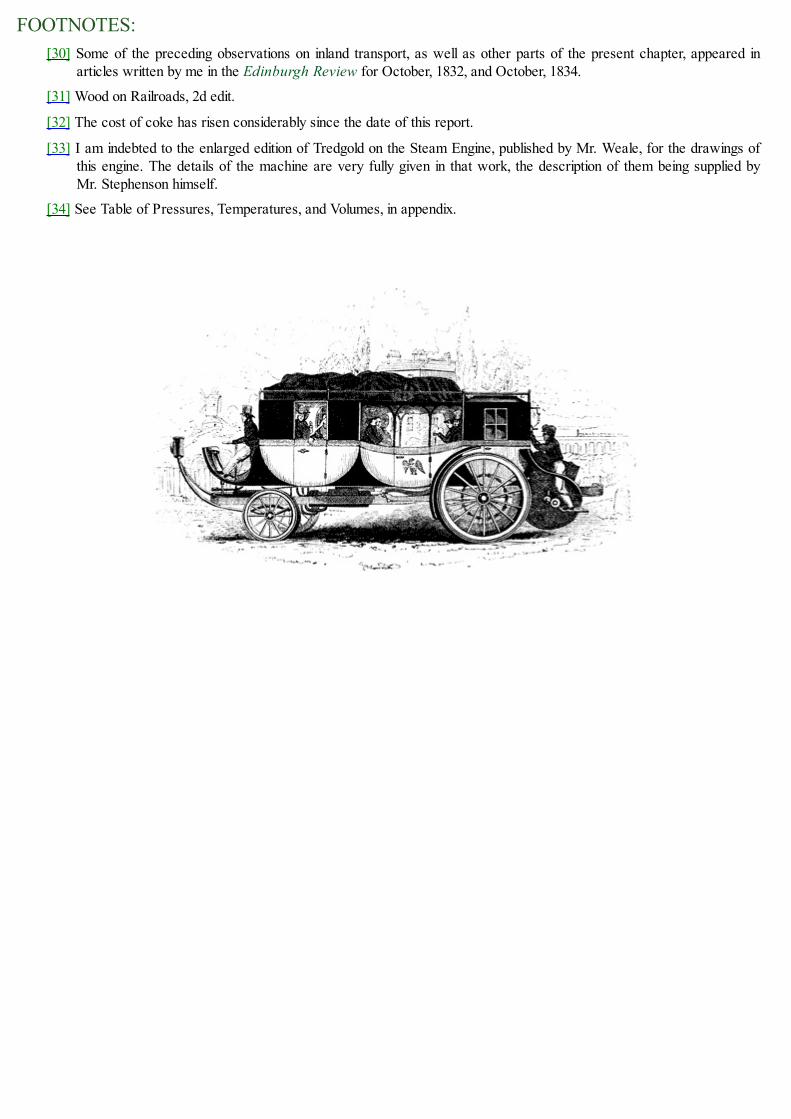
FOOTNOTES:[30] Some of the preceding observations on inland transport, as well as other parts of the present chapter, appeared in
articles written by me in the Edinburgh Review for October, 1832, and October, 1834.
[31] Wood on Railroads, 2d edit.
[32] The cost of coke has risen considerably since the date of this report.
[33] I am indebted to the enlarged edition of Tredgold on the Steam Engine, published by Mr. Weale, for the drawings ofthis engine. The details of the machine are very fully given in that work, the description of them being supplied byMr. Stephenson himself.
[34] See Table of Pressures, Temperatures, and Volumes, in appendix.

CHAP. XII.
LOCOMOTIVE ENGINES ON TURNPIKE ROADS.[Pg419]
TOC INX
RAILWAYS AND STONE ROADS COMPARED.—MR. GURNEY'S STEAM ENGINE.—CONVENIENCE AND SAFETYOF STEAM CARRIAGES.—HANCOCK'S STEAM ENGINE.—OGLE'S STEAM ENGINE.—TREVETHICK'SINVENTION.—DR. CHURCH'S STEAM ENGINE.
(203.) We have hitherto confined our observations on steam-power, as a means of transport byland, to its application on railways. But modern speculation has not stopped there; variousattempts have been made, and attended with more or less success, to work steam-carriages oncommon roads. The mere practicability of this project had long been regarded as veryquestionable; but enough has been done to show that the only doubt which can attend it, is as towhether it can be profitably resorted to, as a means of transport, and this question [Pg420] has beenmaterially affected by the recent extension of railways. In comparing the effect of a stone road withan iron railway, there are two circumstances which give great superiority and advantage to thelatter: first, the resistance opposed by a railway to the moving power, no matter what that movingpower may be, is considerably less in proportion to the load than on a stone road. The averageresistance on a good level stone road, to the motion of carriages drawn at the speed usuallyattained by the application of horse-power, may be taken at about a thirty-sixth part of the load,while the resistance to a load drawn upon a railway at the same speed probably does not amountto a tenth part of this resistance. Thus the moving power, whatever it may be, would produce on arailway ten times the useful effect which it would produce on a stone road; secondly, the resistancewhich is opposed to the moving power on a level railway is much more uniform than on a stoneroad, and, consequently, the moving power is less subjected to jerks and inequalities. This rendersthe application of inanimate power more easy on the railway. Those inequalities of surface whichincrease the amount of resistance on stone roads as compared with railways also produce a joltingmotion in the carriage, to counteract which, the use of springs become necessary. These springsrender the motion of that part of the carriage which rests upon them different from that part of thecarriage which supports them; and in the application of steam-machinery it becomes necessary soto connect the moving power with the wheels that the machinery may have one motion, and thewheels which are put in mechanical connexion with that machinery, and driven by it, shall haveanother motion. This, it is true, is the case with locomotive engines on railways; but owing to thegreater smoothness and equality of the railway surface the difference between the motion of thecarriage body suspended on springs and that of the wheels is much less than it would be on a stoneroad.
But besides the greater smoothness of railways compared with stone roads, the latter haveanother disadvantage, the effects of which have probably been exaggerated by those who areopposed to this application of steam-power. One of the [Pg421] laws of adhesion long sincedeveloped by experiment, and established as a principle of practical science, is that the adhesionis greater between surfaces of the same than between surfaces of a different kind. Thus betweentwo metals of the same kind, the adhesion corresponding to any given pressure is greater thanbetween two metals of different kinds; between two metals of any sort the adhesion is greater than

between metal and stone, or between metal and wood. Hence, the wheels of steam-carriagesrunning on a railroad have a greater adhesion with the road, and therefore offer a greater resistanceto slip round without the advance of the carriage, than wheels would offer on a turnpike road; foron a railroad the iron tire of the wheel rests in contact with the iron rail, while on a common roadthe iron tire rests in contact with the surface of stone, or whatever material the road may becomposed of. Besides this, the dust and loose matter which necessarily collect on a common road,when pressed between the wheels and the solid base of the road, act somewhat in the manner ofrollers, and give the wheels a greater facility to slip than if the road were swept clean, and thewheels rested in immediate contact with its hard surface. The truth of this observation is illustratedon the railroads themselves, where the adhesion is found to be diminished whenever the rails arecovered with any extraneous matter, such as dust or moist clay. Although the adhesion of thewheels of a carriage with a common road, however, be less than those of the wheels of a steam-carriage with a railroad, yet still the actual adhesion on turnpike roads is greater in amount thanhas been generally supposed, and is quite sufficient to propel carriages drawing after them loadsof large amount.
The relative facility with which carriages are propelled on railroads and turnpike-roads equallyaffects any moving power, whether that of horses or steam engines; and whether loads bepropelled by the one power or the other, the railroad, as compared with the turnpike-road, willalways possess the same proportionate advantage; and a given amount of power, whether of theone kind or the other, will always perform a quantity of work less in the same proportion on a [Pg422]
turnpike-road than on a rail-road. But, on the other hand, the expense of original construction, andof maintaining the repairs of a rail-road, is to be placed against the certain facility which it offersto draught.
In the attempts which have been made to adapt locomotive engines to turnpike-roads, theprojectors have aimed at the accomplishment of two objects: first, the construction of lighter andsmaller engines; and, secondly, increased power. These ends, it is plain, can only be attained, withour present knowledge, by the production of steam of very high temperature and pressure, so thatthe smallest volume of steam shall produce the greatest possible mechanical effect. The methods ofpropelling the carriage have been in general similar to that used in the railroad engines, viz. eitherby cranks placed on the axles, the wheels being fixed upon the same axles, or by connecting thepiston rods with the spokes of the wheels. In some carriages, the boiler and moving power, and thebody of the carriage which bears the passengers, are placed on the same wheels. In others, theengine is placed on a separate carriage, and draws after it the carriage which transports thepassengers, as is always the case on railways.
The chief difference between the steam engines used on railways, and those adapted to propelcarriages on turnpike roads, is in the structure of the boiler. In the latter it is essential that, whilethe power remains undiminished, the boiler should be lighter and smaller. The accomplishment ofthis has been attempted by various contrivances for so distributing the water as to expose aconsiderable quantity of surface in contact with it to the action of the fire: spreading it in thinlayers on flat plates; inserting it between plates of iron placed at a small distance asunder, the firebeing admitted between the intermediate plates; dividing it into small tubes, round which the firehas play; introducing it between the surfaces of cylinders placed one within another, the fire beingadmitted between the alternate cylinders,—have all been resorted to by different projectors.
(204.) First and most prominent in the history of the application of steam to the propelling of

carriages on turnpike roads stands the name of Mr. Goldsworthy Gurney, a medical [Pg423]
gentleman, and scientific chemist, of Cornwall. In 1822, Mr. Gurney succeeded Dr. Thompson aslecturer on chemistry at the Surrey Institution; and, in consequence of the results of someexperiments on heat, his attention was directed to the project of working steam-carriages oncommon roads; and he subsequently devoted his exertions in perfecting a steam-engine capable ofattaining the end he had in view.
The mistake which so long prevailed in the application of locomotives on railroads, and which,as we have shown, materially retarded the progress of that invention, was shared by Mr. Gurney.Without reducing the question to the test of experiment, he took for granted, in his first attempts,that the adhesion of the wheels with the road was too slight to propel the carriage. He was assured,he says, by eminent engineers, that this was a point settled by actual experiment. It is strange,however, that a person of his quickness and sagacity did not inquire after the particulars of these"actual experiments." So, however, it was; and, taking for granted the inability of the wheels topropel, he wasted much labour and skill in the contrivance of levers and propellers, which actedon the ground in a manner somewhat resembling the feet of horses, to drive the carriage forward.After various fruitless attempts of this kind, the experience acquired in the trials to which theygave rise at last forced the truth upon his notice, and he found that the adhesion of the wheels wasnot only sufficient to propel the carriage heavily laden on level roads, but was capable of causingit to ascend all the hills which occur on ordinary turnpike-roads. In this manner it ascended all thehills between London and Barnet, London and Stanmore, Stanmore Hill, Brockley Hill, andmounted Old Highgate Hill, the last at one point rising one foot in nine.
Fig. 114.

Fig. 115.
The boiler of Mr. Gurney's engine is so constructed, that there is no part of it in which metalexposed to the action of the fire is out of contact with water. If it be considered how rapidly theaction of an intense furnace destroys metal when water is not present to prevent the heat fromaccumulating, the advantage of this circumstance will be appreciated. In the boiler of Mr. Gurney,the grate-bars [Pg424] themselves are tubes filled with water, and form, in fact, a part of the boileritself. This boiler consists of three strong metal cylinders placed in a horizontal position oneabove the other. A section, made by a perpendicular or vertical plane, is represented in fig. 114.The ends of the three cylinders just mentioned are represented at D, H, and I. In the side of thelowest cylinder D are inserted a row of tubes, a ground plan of which is represented in fig. 115.These tubes, proceeding from the side of the lowest cylinder D, are inclined [Pg425] slightly upwards,for a reason which I shall presently explain. From the nature of the section, only one of these tubesis visible in fig. 114. at C. The other extremities of these tubes at A are connected with the samenumber of upright tubes, one of which is shown at E. The upper extremities G of these upright tubesare connected with another set of tubes K, equal in number, proceeding from G, inclining slightlyupwards, and terminating in the second cylinder H.

Fig. 116.
An end view of the boiler is exhibited in fig. 116., where the three cylinders are expressed bythe same letters. Between the cylinders D and H there are two tubes of communication B, and twosimilar tubes between the cylinders H and I. From the nature of the section these appear only as asingle tube in fig. 114. From the top of the cylinder I proceeds a tube N, by which steam isconducted to the engine.
It will be perceived that the space F is enclosed on every side by a grating of tubes, which havefree communication with the cylinders D and H, which cylinders have also a free communicationwith each other by the tubes B. It follows, [Pg426] therefore, that if water be supplied to the cylinder I,it will descend through the tubes, and first filling the cylinder D and the tubes C, will gradually risein the tubes B and E, will next fill the tubes K and the cylinder H. The grating of water-pipes C E K
forms the furnace, the pipes C being the fire-bars, and the pipes E and K being the back and roof ofthe stove. The fire-door, for the supply of fuel, appears at M, fig. 116. The flue issuing between thetubes F is conducted over the tubes K, and the flame and hot air are carried off through a chimney.That portion of the heat of the burning fuel, which in other furnaces destroys the bars of the grate, ishere expended in heating the water contained in the tubes C. The radiant heat of the fire acts uponthe tubes K, forming the roof of the furnace, on the tube E at the back of it, and partially on thecylinders D and H, and the tubes B. The draft of hot air and flame passing into the flue at A actsupon the posterior surfaces of the tubes E, and the upper sides of the tubes K, and finally passesinto the chimney.
As the water in the tubes C E K is heated, it becomes specifically lighter than water of a lesstemperature, and consequently acquires a tendency to ascend. It passes, therefore, rapidly into H.Meanwhile the colder portions descend, and the inclined positions of the tubes C and K give playto this tendency of the heated water, so that a prodigiously rapid circulation is produced, when thefire begins to act upon the tubes. When the water acquires such a temperature that steam is rapidlyproduced, steam-bubbles are constantly formed in the tubes surrounding the fire; and if these

remained stationary in the tubes, the action of the fire would not only decompose the steam, butrender the tubes red hot, the water not passing through them to carry off the heat. But the inclinedposition of the tubes, already noticed, effectually prevents this injurious consequence. A steam-bubble, which is formed either in the tubes C or K, having a tendency to ascend proportional to itslightness as compared with water, necessarily rushes upwards; if in C towards A, and if in K
towards H. But this motion of the steam is also aided by the rapid circulation of the water which iscontinually maintained [Pg427] in the tubes, otherwise it might be possible, notwithstanding the levityof steam compared with water, that a bubble might remain in a narrow tube without rising. To bringthe matter to the test of experiment, I have connected two cylinders, such as D and H, by a system ofglass tubes, such as represented at C E K. The rapid and constant circulation of the water was thenmade evident: bubbles of steam were formed in the tubes, it is true; but they passed with greatrapidity into the upper cylinder, and rose to the surface, so that the glass tubes never acquired ahigher temperature than that of the water which passed through them.
Every part of the boiler being cylindrical, it has the form which, mechanically considered, ismost favourable to strength, and which, within given dimensions, contains the greatest quantity ofwater. It is also free from the defects arising from unequal expansion, which are found to be mostinjurious in tubular boilers. The tubes C and K can freely expand in the direction of their length,without being loosened at their joints, and without straining any part of the apparatus; the tubes E,being short, are subject to a very slight degree of expansion; and it is obvious that the long tubes,with which they are connected, will yield to this without suffering a strain, and without causing anypart of the apparatus to be loosened.
When water is converted into steam, any foreign matter which may be combined with it isdisengaged, and is deposited on the bottom of the vessel in which the water is evaporated. Allboilers, therefore, require occasional cleansing, to prevent the crust thus formed fromaccumulating; and this operation, for obvious reasons, is attended with peculiar difficulty intubular boilers. In the case before us, the crust of deposited matter would gather and thicken in thetubes C and K, and if not removed, would at length choke them. But besides this, it would beattended with a still worse effect; for, being a bad conductor, it would intercept the heat in itstransit from the fire to the water, and would cause the metal of the tube to become unduly heated.Mr. Gurney of course foresaw this inconvenience, and contrived an ingenious chemical method ofremoving it, by occasionally injecting [Pg428] through the tubes such an acid as would combine withthe deposit, and carry it away. This method was effectual; and although its practical applicationwas found to be attended with difficulty in the hands of common workmen, Mr. Gurney waspersuaded to adhere to it by the late Dr. Wollaston, until experience proved the impossibility ofgetting it effectually performed, under the circumstances in which boilers are commonly used. Mr.Gurney then adopted a method of removing the deposit by mechanical means. Opposite the mouthsof the tubes, and on the other side of the cylinders D and H, are placed a number of holes, which,when the boiler is in use, are stopped by pieces of metal screwed into them. When the tubesrequire to be cleaned, these stoppers are removed, and an iron scraper is introduced through theholes into the tubes, which, being passed backwards and forwards, removes the deposit.
In these engines the draught through the furnace was produced by projecting the waste steam upthe chimneys as is practised in railway engines; a method so perfectly effectual, that it is unlikelyto be superseded by any other. The objection which has been urged against it in locomotiveengines, working on turnpike-roads, is, that the noise which it produces has a tendency to frighten

horses.
In the engines on the Liverpool road, the steam is allowed to pass directly from the eductionpipe of the cylinder to the chimney, and it there escapes in puffs corresponding with the alternatemotion of the pistons, and produces a noise, which, although attended with no inconvenience on therailroad, would perhaps be objectionable on turnpike-roads. In the engine used in Mr. Gurney'ssteam-carriage, the steam which passes from the cylinders is conducted to a receptacle, which hecalls a blowing box. This box serves the same purpose as the upper chamber of a smith's bellows.It receives the steam from the cylinders in alternate puffs, but lets it escape into the chimney in acontinued stream by a number of small jets. Regular draught is by this means produced, and nonoise is perceived. Another exit for the steam is also provided, by which the conductor is enabledto increase or diminish, or to suspend altogether, the draught [Pg429] in the chimney, so as to adapt theintensity of the fire to the exigencies of the road. This is a great convenience in practice; becauseon some roads a draught is scarcely required, while on others a powerful blast is indispensable.
Connected with this blowing box is another apparatus of considerable practical importance. Thepipe through which the feeding water is conducted from the tank is carried through this blowingbox, within which it is coiled in a spiral form, so that an extensive thread of the water is exposedto the heat of the waste steam which has escaped from the cylinders, and which is enclosed in thisblowing box. In passing through this pipe the feeding water is raised from the ordinary temperatureof about 60° to the temperature of 212°. Fuel is thus economised and weight diminished; but thereis another still greater advantage attending this process. The feeding water in the worm justmentioned, while it takes up the heat from the surrounding steam in the blowing box, condenses apart of the waste steam, which is thence conducted to the tank, from which the feeding water ispumped.
When steam is generated so rapidly as is necessarily the case in locomotive boilers, it riseswith great violence in numerous bubbles from the bottom of the boiler to the surface of the water,and puts the liquid into a state of foaming turbulence not unlike the sea in a storm. As the steamrushes from the surface into the upper part of the boiler, under these circumstances, it carries withit a spray by which water is scattered in minute subdivision among the steam, and floats there likethe spray which rises from the base of a cascade. If the steam be conducted immediately to thecylinder from the boiler in this state, it will carry with it the water which is thus suspended in it,which will pass through the cylinder, and finally be driven into the atmosphere upon the returningstroke of the piston. The hot water thus carried off possesses none of the mechanical properties ofsteam, and is wholly inefficient as a moving power, and is therefore an extensive source of thewaste of heat. In every boiler, some means should be provided for the separation of the water thussuspended in the steam, before the steam is conducted to the cylinder. In ordinary boilers, the largespace which [Pg430] remains above the surface of the water serves this purpose. The steam beingthere subject to no agitation or disturbance, the water mechanically suspended in it descends by itsown gravity, and leaves pure steam in the upper part. In the small tubular boilers, this has been amatter, however, of greater difficulty. The contracted space in which the ebullition takes placecauses the water to be mixed with the steam in a greater quantity than could happen in commonboilers; and the want of the same steam-room renders the separation of the water from the steam amatter of some difficulty. These inconveniences have been attempted to be overcome by variouscontrivances. I have already described the rapid and regular circulation effected by thearrangement of the tubes. By this a regularity in the currents is established, which has a tendency to

diminish the mixture of water with the steam. In addition to this, a method of separation isprovided in the vessel I, which is a strong iron cylinder of some magnitude, placed out of theimmediate influence of the fire. A partial separation of the steam from the water takes place in thecylinder H; and the steam with the water mechanically suspended in it, technically called moiststeam, rises into the separator I. Here, being free from all agitation and currents, and being, in fact,quiescent, the particles of water fall to the bottom, while the pure steam remains at the top. Thisseparator, therefore, serves all the purposes of the steam-room above the surface of the water inthe large plate boilers. The dry steam is thus collected and ready for the supply of the enginethrough the tube N, while the water, which is disengaged from it, is collected at the bottom of theseparator, and is conducted through the tube T to the lowest vessel D, to be again circulated throughthe boiler.
The pistons of the engine work on the axles of the hind wheels of the carriage which bears theengine, by cranks, as in the locomotives on the Manchester railway, so that the axle is kept in aconstant state of rotation while the engine is at work. The wheels placed on this axle are notpermanently fixed or keyed upon it, as in the Manchester locomotives; but they are capable ofturning upon it in the same manner as ordinary carriage wheels. Immediately within [Pg431] thesewheels there are fixed upon the axles two projecting spokes or levers, which revolve with theaxle, and which take the position of two opposite spokes of the wheel. These may be occasionallyattached to the wheel or detached from it; so that they are capable of compelling the wheels to turnwith the axle, or leaving the axle free to turn independently of the wheel, or the wheel independentof the axle, at the pleasure of the conductor. It is by these levers that the engine is made to propeleither or both of the wheels. If both pairs of spokes are thrown into connexion with the wheels, thecrank shaft or axle will cause both wheels to turn with it, and in that case the operation of thecarriage is precisely the same as those of the locomotives already described upon the Liverpooland Manchester line; but this is rarely found to be necessary, since the adhesion of one wheel withthe road is generally sufficient to propel the carriage, and consequently only one pair of these fixedlevers are used, and the carriage propelled by only one of the two hind wheels. The fore wheels ofthe carriage turn upon a pivot similar to those of a four-wheeled coach. The position of thesewheels is changed at pleasure by a pinion and circular rack, which is moved by the conductor, andin this manner the carriage is guided with precision and facility.
The force of traction necessary to propel a carriage upon common roads must vary with thevariable quality of the road, and consequently the propelling power, or the pressure upon thepistons of the engine, must be susceptible of a corresponding variation; but a still greater variationbecomes necessary from the undulations and hills which are upon all ordinary roads. Thisnecessary change in the intensity of the impelling power is obtained by restraining the steam in theboiler by the throttle-valve, as already described in the locomotive engines on the railroad. Thisprinciple, however, is carried much further in the present case. The steam in the boiler maybe at apressure of from 100 to 200 lbs. on the square inch; while the steam on the working piston may notexceed 30 or 40 lbs. on the inch. Thus an immense increase of power is always at the command ofthe conductor; so that when a hill is encountered, or a rough piece of road, [Pg432] he is enabled tolay on power sufficient to meet the exigency of the occasion.
The two difficulties which have been always apprehended in the practical working of steam-carriages upon common roads are, first, the command of sufficient power for hills and roughpieces of road; and, secondly, the apprehended insufficiency of the adhesion of the wheels with the
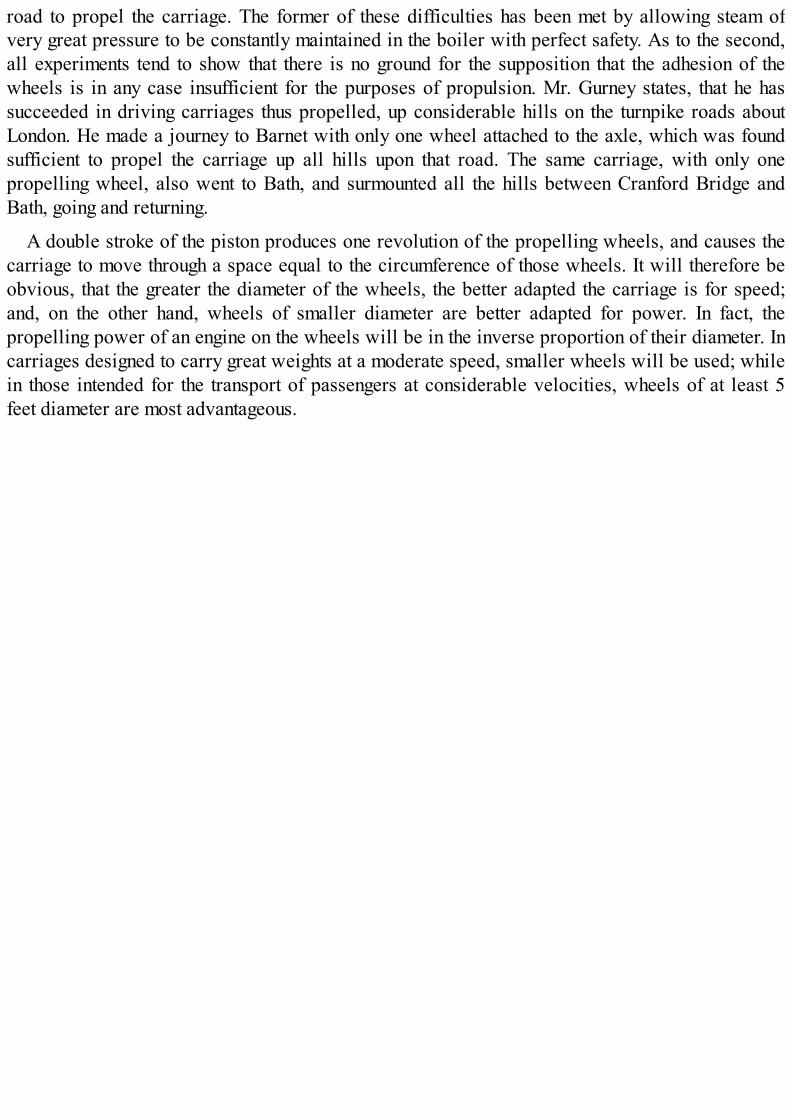
road to propel the carriage. The former of these difficulties has been met by allowing steam ofvery great pressure to be constantly maintained in the boiler with perfect safety. As to the second,all experiments tend to show that there is no ground for the supposition that the adhesion of thewheels is in any case insufficient for the purposes of propulsion. Mr. Gurney states, that he hassucceeded in driving carriages thus propelled, up considerable hills on the turnpike roads aboutLondon. He made a journey to Barnet with only one wheel attached to the axle, which was foundsufficient to propel the carriage up all hills upon that road. The same carriage, with only onepropelling wheel, also went to Bath, and surmounted all the hills between Cranford Bridge andBath, going and returning.
A double stroke of the piston produces one revolution of the propelling wheels, and causes thecarriage to move through a space equal to the circumference of those wheels. It will therefore beobvious, that the greater the diameter of the wheels, the better adapted the carriage is for speed;and, on the other hand, wheels of smaller diameter are better adapted for power. In fact, thepropelling power of an engine on the wheels will be in the inverse proportion of their diameter. Incarriages designed to carry great weights at a moderate speed, smaller wheels will be used; whilein those intended for the transport of passengers at considerable velocities, wheels of at least 5feet diameter are most advantageous.

(205.) Among the numerous popular prejudices to which this new invention has given rise, oneof the most mischievous in its effects and most glaring in its falsehood, is the notion that carriagesthus propelled are more injurious to roads than carriages drawn by horses. This error has beensuccessfully exposed in the evidence taken before the committee of the [Pg433] House of Commonsupon steam carriages. It is there demonstrated, not only that carriages thus propelled do not wear aturnpike road more rapidly than those drawn by horses, but that, on the other hand, the wear by thefeet of horses is far more rapid and destructive than any which could be produced by the wheels ofcarriages. Steam carriages admit of having the tires of the wheels broad, so as to act upon the roadmore in the manner of rollers, and thereby to give consistency and firmness to the material ofwhich the road is composed. The driving wheels being proved not to slip upon the road, do notproduce any effects more injurious than the ordinary rolling wheels; consequently the wearoccasioned by a steam carriage upon a road, is not more than that produced by a carriage drawn byhorses, of an equivalent weight and the same or equal tires; but the wear produced by the poundingand digging of horses' feet in draught is many times greater than that produced by the wear of anycarriage. Those who still have doubts upon this subject, if there be any such persons, will be fullysatisfied by referring to the evidence which accompanies the report of the committee of the Houseof Commons, printed in October, 1831.
The weight of machinery necessary for steam carriages is sometimes urged as an objection totheir practical utility. Mr. Gurney states, that, by successive improvements in the details of themachinery, the weight of his carriages, without losing any of the propelling power, may be reducedto 35 cwt., exclusive of the load, and fuel and water: but thinks that it is possible to reduce theweight still further.
A steam carriage constructed by Mr. Gurney, weighing 35 cwt., working for 8 hours, is found,according to his statement, to do the work of about 30 horses. He calculates that the weight of hispropelling carriage, which would be capable of drawing 18 persons, would be equal to the weightof 4 horses; and the carriage in which these persons would be drawn would have the same weightas a common stage coach capable of carrying the same number of persons. Thus the weight of thewhole—the propelling carriage and the carriage for passengers taken together—would be the same[Pg434] with the weight of a common stage coach, with 4 horses inclusive.
There are two methods of applying locomotives upon common roads to the transport ofpassengers or goods; the one is by causing the locomotive to carry, and the other to draw the load;and different projectors have adopted the one and the other method. Each is attended with itsadvantages and disadvantages. If the same carriage transport the engine and the load, the weight ofthe whole will be less in proportion to the load carried; also a greater pressure may be producedon the wheels by which the load is propelled. It is also thought that a greater facility in turning andguiding the vehicle, greater safety in descending the hills, and a saving in the original cost, will beobtained. On the other hand, when the passengers are placed in the same carriage with the engine,they are necessarily more exposed to the noise of the machinery and to the heat of the boiler andfurnace. The danger of explosion is so slight, that, perhaps, it scarcely deserves to be mentioned;but still the apprehension of danger on the part of the passengers, even though groundless, shouldnot be disregarded. This apprehension will be obviously removed or diminished by transferringthe passengers into a carriage separate from the engine; but the greatest advantage of keeping theengine separate from the passengers is the facility which it affords of changing one engine foranother in case of accident or derangement on the road, in the same manner as horses are changed

at the different stages: or, if such an accident occur in a place where a new engine cannot beprocured, the load of passengers may be carried forward by horses, until it is brought to somestation where a locomotive may be obtained. There is also an advantage arising from thecircumstance, that when the engines are under repair, or in process of cleaning, the carriages forpassengers are not necessarily idle. Thus the same number of carriages for passengers will not berequired when the engine is used to draw as when it is used to carry.
In case of a very powerful engine being used to carry great loads, it would be quiteimpracticable to place the engine [Pg435] and loads on four wheels, the pressure being such as noturnpike road could bear. In this case it would be indispensably necessary to place a part of theload at least upon separate carriages to be drawn by the engine.
In the comparison of carriages propelled by steam with carriages drawn by horses, there is norespect in which the advantage of the former is so apparent as the safety afforded to the passenger.Steam power is under the most perfect control, and a carriage thus propelled is capable of beingguided with the most admirable precision. It is also capable of being stopped almost suddenly,whatever be its speed: it is capable of being turned within a space considerably less than thatwhich would be necessary for four-horse coaches. In turning sharp corners, there is no danger,with the most ordinary care on the part of the conductor. On the other hand, horse power, as is wellknown, is under very imperfect control, especially when horses are used adapted to that speedwhich at present is generally considered necessary for the purposes of travelling. "The danger ofbeing run away with and overturned," says Mr. Farey, in his evidence before the House ofCommons, "is greatly diminished in a steam coach. It is very difficult to control four such horses ascan draw a heavy stage coach ten miles an hour, in case they are frightened or choose to run away;and, for such quick travelling, they must be kept in that state of courage that they are alwaysinclined to run away, particularly down hill, and at sharp turns in the road. Steam power has verylittle corresponding danger, being perfectly controllable, and capable of having its powerreversed, to retard in going down hill. It must be carelessness that would occasion the overturningof a steam carriage. The chance of breaking down has been hitherto considerable, but it will not bemore than in stage coaches when the work is truly proportioned and properly executed. The riskfrom explosion of the boiler is the only new cause of danger, and that I consider not equivalent tothe danger from horses."
That the risk of accident from explosion is extremely slight, may be proved by the fact that therailway between Liverpool and Manchester has now been in operation for about ten [Pg436] years,and that other railways more extensive in length have been worked for a considerable time, andthat no instance has ever yet occurred of an accident to passengers from the explosion of a boiler.Generally these machines, when they fail, are attended with no other effect than the extinction ofthe fire, by the water of the boiler flowing in upon it. I am not aware of more than one instance, inwhich a serious accident has been produced by explosion; and in that instance, the sufferers wereonly the engineer and stoker. In the steam-engine of Mr. Gurney, the carriage is drawn after theengine, as represented in fig. 117.

Fig. 117.
Fig. 118.
(206.) In the boiler to be used in the steam carriage projected by Mr. Walter Hancock, thesubdivision of the water is accomplished by dividing a case or box by a number of [Pg437] thin platesof metal, like a galvanic battery, the water being allowed to flow between every alternate pair ofplates, at E, fig. 118., and the intermediate spaces H forming the flue through which the flame andhot air are propelled.
In fact, a number of thin plates of water are exposed on both sides to the most intense action offlame and heated air; so that steam of a high pressure is produced in great abundance and withconsiderable rapidity. The plates forming the boiler are bolted together by strong iron ties,extending across the boiler, at right angles to the plates, as represented in the figure. The distancebetween the plates is two inches.
There are ten flat chambers of this kind for water, and intermediately between them ten flues.Under the flues is the fire-place, or grate, containing six square feet of fuel in vivid combustion.The chambers are all filled to about two thirds of their depth with water, and the other third is leftfor steam. The water chambers, throughout the whole series, communicate with each other both attop and bottom, and are held together by two large bolts. By releasing these bolts, at any time, thechambers fall asunder; and by screwing them up they may be all made tight again. The water issupplied to the boiler by a forcing-pump, and the steam issues from the centre of one of the flues atthe top.

These boilers are constructed to bear a pressure of 400 or 500 lbs. on the square inch; but theaverage pressure of the steam on the safety valve is from 60 to 100. There are 100 square feet ofsurface in contact with the water exposed to the fire. The stages which such an engine performs areeight miles, at the end of which a fresh supply of fuel and water are taken in. It requires about twobushels of coke for each stage.
The steam carriage of Mr. Hancock differs from that of Mr. Gurney in this—that in the formerthe passengers and engine are all placed on the same carriage. The boiler is placed behind thecarriage; and there is an engine-house between the boiler and the passengers, the latter beingplaced in the fore part of the vehicle; so that all the machinery is behind them. The carriages areadapted to carry 14 [Pg438] passengers, and weigh, exclusive of their load, about 31⁄2 tons, the tiresof the wheels being about 31⁄2 inches in breadth. Mr. Hancock states, that the construction of hisboiler is of such a nature, that, even in the case of bursting, no danger is to be apprehended, norany other inconvenience than the stoppage of the carriage. He states that, while travelling aboutnine miles an hour, and working with a pressure of about 100 lbs. on the square inch, loaded withthirteen passengers, the carriage was suddenly stopped. At first the cause of the accident was notapparent; but, on opening one of the cocks of the boiler, it was found that it contained neither steamnor water. Further examination proved that the boiler had burst. On unscrewing the bolts, it wasfound that there were several large holes in the plates of the water-chamber, through which thewater had flowed on the fire, but neither noise nor explosion, nor any dangerous consequences,ensued.
(207.) Mr. Nathaniel Ogle of Southampton obtained a patent for a locomotive carriage, andworked it for some time experimentally; but as his operations do not appear to have beencontinued, I suppose he was unsuccessful in fulfilling those conditions, without which the machinecould not be worked with economy and profit. In his evidence before a committee of the House ofCommons, he has thus described his contrivance:—
"The base of the boiler and the summit are composed of cross pieces, cylindrical within andsquare without; there are holes bored through these cross pieces, and inserted through the whole isan air tube. The inner hole of the lower surface, and the under hole of the upper surface, are ratherlarger than the other ones. Round the air tube is placed a small cylinder, the collar of which fitsround the larger aperture on the inner surface of the lower frame, and the under surface of theupper frame-work. These are both drawn together by screws from the top; these cross pieces areunited by connecting pieces, the whole strongly bolted together; so that we obtain, in one tenth ofthe space, and with one tenth of the weight, the same heating surface and power as is now obtainedin other and low-pressure boilers, with incalculably [Pg439] greater safety. Our present experimentalboiler contains 250 superficial feet of heating surface in the space of 3 feet 8 inches high, 3 feetlong, and 2 feet 4 inches broad, and weighs about 8 cwt. We supply the two cylinders with steam,communicating by their pistons with a crank axle, to the ends of which either one or both wheelsare affixed as may be required. One wheel is found to be sufficient, except under very difficultcircumstances, and when the elevation is about one foot in six to impel the vehicle forward.
"The cylinders of which the boiler is composed are so small as to bear a greater pressure thancould be produced by the quantity of fire beneath the boiler; and if any one of these cylindersshould be injured by violence, or any other way, it would become merely a safety valve to the rest.We never, with the greatest pressure, burst, rent, or injured our boiler; and it has not once requiredcleaning, after having been in use twelve months."
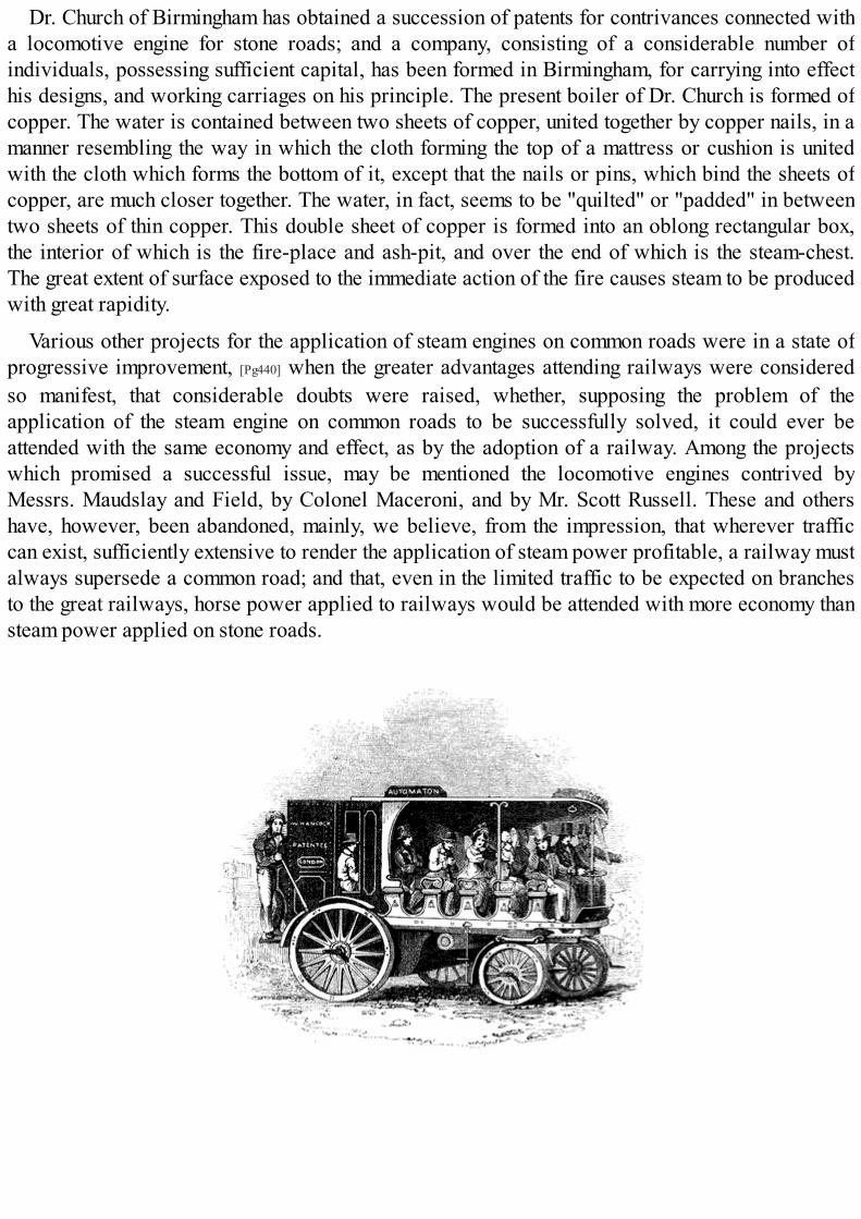
Dr. Church of Birmingham has obtained a succession of patents for contrivances connected witha locomotive engine for stone roads; and a company, consisting of a considerable number ofindividuals, possessing sufficient capital, has been formed in Birmingham, for carrying into effecthis designs, and working carriages on his principle. The present boiler of Dr. Church is formed ofcopper. The water is contained between two sheets of copper, united together by copper nails, in amanner resembling the way in which the cloth forming the top of a mattress or cushion is unitedwith the cloth which forms the bottom of it, except that the nails or pins, which bind the sheets ofcopper, are much closer together. The water, in fact, seems to be "quilted" or "padded" in betweentwo sheets of thin copper. This double sheet of copper is formed into an oblong rectangular box,the interior of which is the fire-place and ash-pit, and over the end of which is the steam-chest.The great extent of surface exposed to the immediate action of the fire causes steam to be producedwith great rapidity.
Various other projects for the application of steam engines on common roads were in a state ofprogressive improvement, [Pg440] when the greater advantages attending railways were consideredso manifest, that considerable doubts were raised, whether, supposing the problem of theapplication of the steam engine on common roads to be successfully solved, it could ever beattended with the same economy and effect, as by the adoption of a railway. Among the projectswhich promised a successful issue, may be mentioned the locomotive engines contrived byMessrs. Maudslay and Field, by Colonel Maceroni, and by Mr. Scott Russell. These and othershave, however, been abandoned, mainly, we believe, from the impression, that wherever trafficcan exist, sufficiently extensive to render the application of steam power profitable, a railway mustalways supersede a common road; and that, even in the limited traffic to be expected on branchesto the great railways, horse power applied to railways would be attended with more economy thansteam power applied on stone roads.
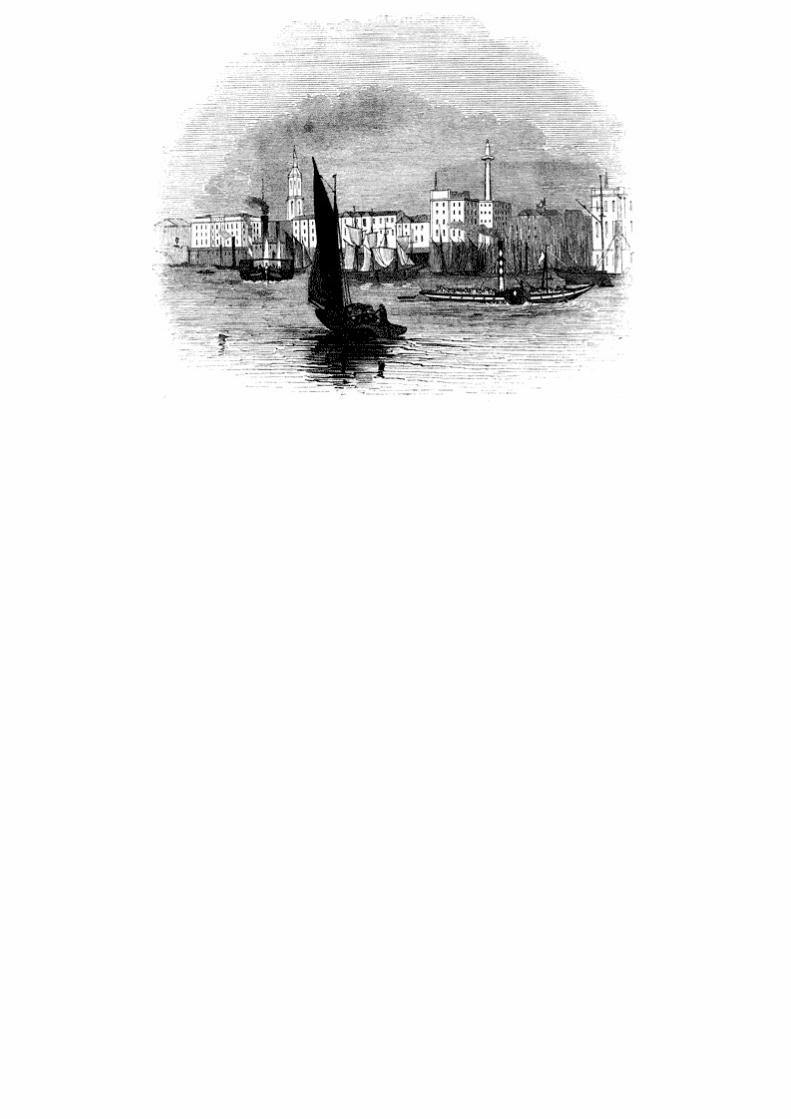

CHAP. XIII.
STEAM NAVIGATION.[Pg441]
TOC INX
FORM AND ARRANGEMENT OF MARINE ENGINES.—EFFECTS OF SEA WATER IN BOILERS.—REMEDIES FORTHEM.—BLOWING OUT.—INDICATORS OF SALTNESS.—SEAWARD'S INDICATOR.—HIS METHOD OFBLOWING OUT.—FIELD'S BRINE PUMPS.—TUBULAR CONDENSERS APPLIED BY MR. WATT.—HALL'SCONDENSERS.—COPPER BOILERS.—PROCESS OF STOKING.—MARINE BOILERS.—MEANS OFECONOMISING FUEL.—COATING MARINE BOILERS WITH FELT.—NUMBER AND ARRANGEMENT OFFURNACES AND FLUES.—HOWARD'S ENGINE.—APPLICATION OF THE EXPANSIVE PRINCIPLE INMARINE ENGINES.—RECENT IMPROVEMENTS OF MESSRS. MAUDSLAY AND FIELD.—HUMPHRYS'ENGINE.—COMMON PADDLE-WHEEL.—FEATHERING PADDLES.—MORGAN'S WHEELS.—THE SPLITPADDLE.—PROPORTION OF POWER TO TONNAGE.—IMPROVED EFFICIENCY OF MARINE ENGINES.—IRON STEAM-VESSELS.—STEAM-NAVIGATION TO INDIA.
(208.) Among the many ways in which the steam-engine has ministered to the advancement ofcivilisation and the social progress of the human race, there is none more [Pg442] important or moreinteresting than its application to navigation. Before it lent its giant powers to the propulsion ofships, locomotion over the waters of the deep was attended with so much danger and uncertaintythat, as a common proverb, it became the type and the representative of every thing which wasprecarious and perilous. The application, however, of steam to navigation has rescued the marinerand the voyager from many of the dangers of wind and water; and even in its present state, puttingout of view its probable improvement, it has rendered all voyages of moderate length as safe, andvery nearly as regular, as journeys over-land. As a means of transport by sea, the application ofthis power may be considered as established; and it is now receiving improvements by which itsextension to the longest class of ocean voyages is a question not of practicability, but merely ofprofit.
The manner in which the steam-engine is rendered an instrument for the propulsion of vesselsmust in its general features be so familiar to every one as to require but short explanation. A shaftis carried across the vessel, being continued on either side beyond the timbers: to the extremitiesof this shaft, on the outside of the vessel, are fixed a pair of wheels constructed like undershotwater-wheels, having attached to their rims a number of flat boards called paddle-boards. As thewheels revolve, these paddle-boards strike the water, driving it in a direction contrary to that inwhich it is intended the vessel should be propelled. The moving force imparted to the water thusdriven backwards is necessarily accompanied by a re-action upon the vessel through the mediumof the paddle-shaft, by which the vessel is propelled forwards. On the paddle-shaft two cranks areconstructed, similar to the cranks already described on the axle of the driving wheels of alocomotive engine. These cranks are placed at right angles to each other, so that when either is inits highest or lowest position the other shall be horizontal. They are driven by two steam-engines,which are placed in the hull of the vessel below the paddle-shaft. In the earlier steam-boats asingle steam-engine was used, and in that case the unequal action of the engine on the crank wasequalised by a fly-wheel. This, however, has been long [Pg443] since abandoned in Europeanvessels, and the use of two engines is now almost universal. By the relative position of the cranksit will be seen, that when either crank is at its dead points, the other will be in the positions most

favourable to its action, and in all intermediate positions the relative efficiency of the cranks willbe such as to render their combined action very nearly uniform.
The steam-engines used to impel vessels may be either condensing engines, similar to those ofWatt, and such as are used in manufactures generally, or they may be non-condensing and high-pressure engines, similar in principle to those used on railways. Low-pressure condensing enginesare, however, universally used for marine purposes in Europe and to some extent in the UnitedStates. In the latter country, however, high-pressure engines are also in pretty general use, on riverswhere lightness is a matter of importance.
The arrangement of the parts of a marine engine differs in some respects from that of a landengine. The limitation of space, which is unavoidable in a vessel, renders greater compactnessnecessary. The paddle-shaft on which the cranks to be driven by the engine are constructed beingvery little below the deck of the vessel, the beam and connecting rod could not be placed in theposition in which they usually are in land engines, without carrying the machinery to aconsiderable elevation above the deck. This is done in the steam-boat engines used on theAmerican rivers; but it would be inadmissible in steam-boats in general, and more especially insea-going steamers. The connecting rods, therefore, instead of being presented downwardstowards the cranks which they drive, must, in steam-vessels, be presented upwards, and theimpelling force received from below. If, under these circumstances, the beam were in the usualposition above the cylinder and piston-rod, it must necessarily be placed between the engine andthe paddle-shaft. This would require a depth for the machinery which would be incompatible withthe magnitude of the vessel. The beam, therefore, of marine engines, instead of being above thecylinder and piston, is placed below them. To the top of the [Pg445] piston-rods cross pieces areattached of greater length than the diameter of the cylinders, so that their extremities shall projectbeyond the cylinders. To the ends of these cross pieces are attached by joints the rods of a parallelmotion: these rods are carried downwards, and are connected with the ends of two beams belowthe cylinder, and placed on either side of it. The opposite ends of these beams are connected byanother cross piece, to which is attached a connecting rod, which is continued upwards to thecrank-pin, to which it is attached, and which it drives. Thus the beam, parallel motion, andconnecting rod of a marine engine, is similar to that of a land engine, only that it is turned upsidedown; and in consequence of the impossibility of placing the beam directly over the piston-rod,two beams and two systems of parallel motion are provided, one on each side of the engine, actedupon by, and acting on the piston-rod and crank by cross pieces.
The proportion of the cylinders differs from that usually observed in land engines, for likereasons. The length of the cylinder of land engines is generally greater than its diameter, in theproportion of about two to one. The cylinders of marine engines are, however, commonlyconstructed with a diameter very little less than their length. In proportion, therefore, to theirpower their stroke is shorter, which infers a corresponding shortness of crank and a greaterlimitation of play of all the moving parts in the vertical direction. The valves and the gearing bywhich they are worked, the air-pump, the condenser, and other parts of the marine engines, do notmaterially differ from those already described in land engines.

Fig. 119.
These arrangements of a marine engine will be more clearly understood by reference to fig. 119.[35], in which is represented a longitudinal section of a marine engine with its boiler as placed in asteam-vessel. The sleepers of oak, supporting the engine, are represented at X, the base of theengine being secured to these by bolts passing through them [Pg446] and the bottom timbers of thevessel; S is the steam-pipe leading from the steam-chest in the boiler to the slides c, by which it isadmitted to the top and bottom of the cylinder. The condenser is represented at B, and the air-pumpat E. The hot well is seen at F, from which the feed is taken for the boiler; L is the piston-rodconnected by the parallel motion a with the beam H, working on a centre K, near the base of theengine. The other end of the beam I drives the connecting rod M, which extends upwards to thecrank which it works upon the paddle-shaft O. Q R is the framing by which the engine is supported.The beam here exhibited is shown on dotted lines as being on the further side of the engine. Asimilar beam similarly placed, and moving on the same axis, must be understood to be at this sideconnected with the cross head of the piston in like manner by a parallel motion, and with a crosspiece attached to the lower end of the connecting rod and to the opposite beam. The eccentricwhich works the slides is placed upon the paddle shaft O, and the connecting arm which drives theslides may be easily detached when the engine requires to be stopped. The section of the boiler,grate, and flues, is represented at W U. The safety-valve y is enclosed beneath a pipe carried upbeside the chimney, and is inaccessible to the engine-man; h are the cocks for blowing the saltedwater from the boiler; and I I the feed-pipe.
The general arrangement of the engine-room of a steam-vessel is represented in fig. 120.
The nature of the effect required to be produced by marine engines does not render eithernecessary or possible that great regularity of action which is indispensable in a steam-engineapplied to the purposes of manufacture. The agitation of the surface of the sea will cause theimmersion of the paddle-wheels to be subject to great variation, and the resistance produced by thewater to the engine will undergo a corresponding change. The governor, therefore, and other partsof the apparatus, contrived for giving to the engine that great regularity required in manufactures,are omitted in nautical engines, and nothing is introduced save what is [Pg447] necessary to maintainthe machine in its full working efficiency.

Fig. 120.
Fig. 121.
To save space, marine boilers are constructed so as to produce the necessary quantity of steamwithin the smallest possible dimensions. With this view a more extensive surface in proportion tothe capacity of the boiler is exposed to the action of the fire. The flues, by which the flame andheated air are conducted to the chimney, are so constructed that the heat may act upon the water onevery side in thin oblong shells or plates. This is accomplished by constructing the flues so as totraverse the boiler backwards and forwards several times before they terminate [Pg448] in thechimney. Such an arrangement renders the expense of the boilers greater, but their steam-producingpower is proportionally augmented, and experiments made by Mr. Watt, at Birmingham, haveproved that such boilers with the same consumption of fuel will produce, as compared withcommon land boilers, an increased evaporation in the proportion of about three to two.

Fig. 122.
Fig. 123.
The form and arrangement of the water-spaces and flues in marine boilers may be collectedfrom the sections of the boilers used in some of the government steamers, exhibited in figs. 121,122, 123. A section made by a horizontal plane passing through the flues is exhibited in fig. 121.The furnaces F communicate in pairs with the flues E, the air following the course through the fluesrepresented by the arrows. The flue E passes to the back of the boiler, then returns to the front, thento the back again, and is finally carried back to the front, where it communicates at C with thecurved flue B, represented in the transverse vertical section, fig. 122. This curved flue B finallyterminates in the chimney A. There are in this case three independent boilers, each worked by twofurnaces communicating with the same system of flues; and in the curved flues B, fig. 122., bywhich the air is finally conducted through the chimney, are placed three independent [Pg449] dampers,by means of which the furnace of each boiler can be regulated independently of the other, and bywhich each boiler may be separately detached from communication with the chimney. The lettersof reference in the horizontal section, fig. 121., correspond with those in the transverse verticalsection, fig. 122., E representing the commencement of the flues, and C their termination.

Fig. 124.
A longitudinal section of the boiler made by a vertical plane extending from the front to the backis given in fig. 123., where F, as before, is the furnace, G the grate-bars sloping downwards fromthe front to the back, H the fire-bridge, C the commencement of the flues, and A the chimney. Anelevation of the front of the boiler is represented in fig. 124., showing two of the fire-doorsclosed, and the other two removed, displaying the position of the grate-bars in front. Smallopenings are also provided, closed by proper doors, by which access can be had to the under sideof the flues between the foundation timbers of the engine for the purpose of cleaning them.
Each of these boilers can be worked independently of the others. By this means, when at sea, theengine may be worked by any two of the three boilers, while the third is being cleaned and put inorder. In all sea-going steamers multiple boilers are at present provided for this purpose.
In the boilers here represented the flues are all upon the same level, winding backwards andforwards without passing one above the other. In other boilers, however, the flues, [Pg450] afterpassing backwards and forwards near the bottom of the boiler, turn upwards and pass backwardsand forwards through a level of the water nearer its surface, finally terminating in the chimney.More heating surface is thus obtained with the same capacity of boiler.
The most formidable difficulty which has been encountered in the application of the steam-engine to sea-voyages has arisen from the necessity of supplying the boiler with sea-water insteadof pure fresh water. The sea-water is injected into the condenser for the purpose of condensing thesteam, and it is thence, mixed with the condensed steam, conducted as feeding water into theboiler.
(209.) Sea-water holds, as is well known, certain alkaline substances in solution, the principalof which is muriate of soda, or common salt. Ten thousand grains of pure sea-water contain twohundred and twenty grains of common salt, the remaining ingredients being thirty-three grains ofsulphate of soda, forty-two grains of muriate of magnesia, and eight grains of muriate of lime. Theheat which converts pure water into steam does not at the same time evaporate those salts whichthe water holds in solution. As a consequence it follows, that as the evaporation in the boiler iscontinued, the salt, which was held in solution by the water which has been evaporated, remains inthe boiler, and enters into solution with the water remaining in it. The quantity of salt contained insea-water being considerably less than that which water is capable of holding in solution, theprocess of evaporation for some time is attended with no other effect than to render the water inthe boiler a stronger solution of salt. If, however, this process be continued, the quantity of saltretained in the boiler having constantly an increasing proportion to the quantity of water, it must at

length render the water in the boiler a saturated solution—that is, a solution containing as muchsalt as at the actual temperature it is capable of holding in solution. If, therefore, the evaporationbe continued beyond this point, the salt disengaged from the water evaporated instead of enteringinto solution with the water remaining in the boiler will be precipitated in the form of sediment;and if the process be continued in the [Pg451] same manner, the boiler would at length become a meresalt-pan.
But besides the deposition of salt sediment in a loose form, some of the constituents of sea-water having an attraction for the iron of the boiler, collect upon it in a scale or crust in the samemanner as earthy matters held in solution by spring-water are observed to form and becomeincrusted on the inner surface of land-boilers and of common culinary vessels.
The coating of the inner surface of a boiler by incrustation and the collection of salt sediment inits lower parts, are attended with effects highly injurious to the materials of the boiler. The crustand sediment thus formed within the boiler are almost non-conductors of heat, and placed, as theyare, between the water contained in the boiler and the metallic plates which form it, they obstructthe passage of heat from the outer surface of the plates in contact with the fire to the water. Theheat, therefore, accumulating in the boiler-plates so as to give them a much higher temperature thanthe water within the boiler, has the effect of softening them, and by the unequal temperature whichwill thus be imparted to the lower plates which are incrusted, compared with the higher partswhich may not be so, an unequal expansion is produced, by which the joints and seams of theboiler are loosened and opened, and leaks produced.
These injurious effects can only be prevented by either of two methods; first, by so regulatingthe feed of the boiler that the water it contains shall not be suffered to reach the point of saturation,but shall be so limited in its degree of saltness that no injurious incrustation or deposit shall beformed; secondly, by the adoption of some method by which the boiler may be worked with freshwater. This end can only be attained by condensing the steam by a jet of fresh water, and workingthe boiler continually by the same water, since a supply of fresh water sufficient for a boilerworked in the ordinary way could never be commanded at sea.
(210.) The method by which the saltness of the water in the boiler is most commonly preventedfrom exceeding a certain [Pg452] limit has been to discharge from the boiler into the sea a certainquantity of over-salted water, and to supply its place by sea-water introduced into the condenserthrough the injection-cock for the purpose of condensing the steam, this water being mixed with thesteam so condensed, and being, therefore, a weaker solution of salt than common sea-water. Toeffect this, cocks called blow-off cocks, are usually placed in the lower parts of the boiler, wherethe over-salted, and therefore heavier, parts of the water collect. The pressure of the steam andincumbent weight of the water in the boiler force the lower strata of water out through these cocks;and this process, called blowing out, is, or ought to be, practised at such intervals as will preventthe water from becoming over salted. When the salted water has been blown out in this manner, thelevel of the water in the boiler is restored by a feed of corresponding quantity.
This process of blowing out, on the due and regular observance of which the preservation andefficiency of the boiler mainly depend, is too often left at the discretion of the engineer, who is, inmost cases, not even supplied with the proper means of ascertaining the extent to which theprocess should be carried. It is commonly required that the engineer should blow out a certainportion of the water in the boiler every two hours, restoring the level by a feed of equivalentamount; but it is evident that the sufficiency of the process founded on such a rule must mainly

depend on the supposition that the evaporation proceeds always at the same rate, which is far frombeing the case with marine boilers. An indicator, by which the saltness of the water in the boilerwould always be exhibited, ought to be provided, and the process of blowing out should beregulated by the indications of that instrument. To blow out more frequently than is necessary isattended with a waste of fuel; for hot water is thus discharged into the sea while cold water isintroduced in its place, and consequently all the heat necessary to produce the difference of thetemperatures of the water blown out and the feed introduced is lost. If, on the other hand, theprocess of blowing out be observed less frequently than is necessary, then more or lessincrustation and deposit [Pg453] may be produced, and the injurious effects already described ensue.
As the specific gravity of water holding salt in solution is increased with every increase of thestrength of the solution, any form of hydrometer capable of exhibiting a visible indication of thespecific gravity of the water contained in the boiler would serve the purpose of an indicator, toshow when the process of blowing out is necessary, and when it has been carried to a sufficientextent. The application of such instruments, however, would be attended with some practicaldifficulties in the case of sea-boilers.
The temperature at which a solution of salt boils under a given pressure varies considerablywith the strength of the solution; the more concentrated the solution is, the higher will be its boilingtemperature under the same pressure. A comparison, therefore, of a steam-gauge attached to theboiler, and a thermometer immersed in it, showing the pressure and the temperature, would alwaysindicate the saltness of the water; and it would not be difficult so to graduate these instruments asto make them at once show the degree of saltness.
If the application of the thermometer be considered to be attended with practical difficulty, thedifference of pressures under which the salt water of the boiler and fresh water of the sametemperature boil, might be taken as an indication of the saltness of the water in the boiler, and itwould not be difficult to construct upon this principle a self-registering instrument, which wouldnot only indicate but record from hour to hour the degree of saltness of the water. A small vessel ofdistilled water being immersed in the water of the boiler would always have the temperature ofthat water, and the steam produced from it communicating with a steam-gauge, the pressure of suchsteam would be indicated by that gauge, while the pressure of the steam in the boiler under whichpressure the salted water boils might be indicated by another gauge. The difference of thepressures indicated by the two gauges would thus become a test by which the saltness of the waterin the boiler would be measured. The two pressures might be made to act on opposite ends of thesame column of [Pg454] mercury contained in a siphon tube, and the difference of the levels of thetwo surfaces of the mercury would thus become a measure of the saltness of the water in the boiler.A self-registering instrument founded on this principle formed part of the self-registering steam-logwhich I proposed to introduce into steam-vessels some time since.
(211.) The Messrs. Seaward of Limehouse have adopted, in some of their recently constructedengines, a method of indicating the saltness of the water, and of measuring the quantity of saltedwater or brine discharged, by blowing out. A glass-gauge, similar in form to that already describedin land engines (156.), is provided to indicate the position of the surface of the water in the boiler.In this gauge two hydrometer balls are provided, the weight of which in proportion to theirmagnitude is such that they would both sink to the bottom in a solution of salt of the same strengthas common sea-water. When the quantity of salt exceeds 5⁄32 parts of the whole weight of the water,the lighter of the two balls will float to the top; and when the strength is further increased until the

proportion of salt exceeds 6⁄32 parts of the whole, then the heavier ball will float to the top. Theactual quantity of salt held in solution by sea-water in its ordinary state is 1⁄32 part of its wholeweight; and when by evaporation the proportion of salt in solution has become 9⁄32 parts of thewhole, then a deposition of salt commences. With an indicator such as that above described, theascent of the lighter hydrometer ball gives notice of the necessity for blowing out, and the ascent ofthe heavier may be considered as indicating the approach of an injurious state of saltness in theboiler.
Fig. 125.
The ordinary method of blowing out the salted water from a boiler is by a pipe having a cock init leading from the boiler through the bottom of the ship, or at a point low down at its side.Whenever the engineer considers that the water in the boiler has become so salted that the processof blowing out should commence, he opens the cock communicating by this pipe with the sea, andsuffers an indefinite and uncertain quantity of water to escape. In this way he discharges, accordingto the magnitude of the boiler, from two to six tons [Pg455] of water, and repeats this at intervals offrom two to four hours, as he may consider to be sufficient. If, by observing this process, heprevents the boiler from getting incrusted during the voyage, he considers his duty to be effectuallydischarged, forgetting that he may have blown out many times more water than is necessary for thepreservation of the boiler, and thereby produced a corresponding and unnecessary waste of fuel. Inorder to limit the quantity of water discharged, Messrs. Seaward have adopted the followingmethod. In fig. 125. is represented a transverse section of a part of a steam-vessel; W is the water-line of the boiler, B is the mouth of a blow-off pipe, placed near the bottom of the boiler. This piperises to A, and turning in the horizontal direction, A C is conducted to a tank T, which containsexactly a ton of water. This pipe communicates with the tank by a cock D, governed by a lever H.When this lever is moved to D′, the cock D is open, and when it is moved to K, the cock D is closed.From the same tank there proceeds another pipe E, which issues from the side of the [Pg456] vessel
into the sea governed by a cock F, which is likewise put in connection with the lever H, so that itshall be opened when the lever H is drawn to the position F′, the cock D′ being closed in allpositions of the lever between K and F′. Thus, whenever the cock F communicating with the sea isopen, the cock D communicating with the boiler is closed, and vice versâ, both cocks being closedwhen the lever is in the intermediate position K. By this arrangement the boiler cannot, by anyneglect in blowing off, be left in communication with the sea, nor can more than a ton of water bedischarged except by the immediate act of the engineer. The injurious consequences are thusprevented which sometimes ensue when the blow-off cocks are left open by any neglect on the partof the engineer. When it is necessary to blow off, the engineer moves the lever H, to the position D′.The pressure of the steam in the boiler on the surface of the water W forces the salted water orbrine up the pipe B A, and through the open cock C into the tank, and this continues until the tank isfilled: when that takes place, the lever is moved from the position D′ to the position F′, by which thecock D is closed, and the cock F opened. The water in the tank flows through the pipe E into thesea, air being admitted through the valve V, placed at the top of the tank, opening inwards. Asecond ton of brine is discharged by moving the lever back to the position D′, and subsequentlyreturning it to the position F′; and in this way the brine is discharged ton by ton, until the supply ofwater from the feed which replaces it has caused both the balls in the indicator to sink to thebottom.

(212.) A different method of preserving the requisite freshness of the water in the boiler hasbeen adopted by Messrs. Maudslay and Field, and introduced with success into the Great Westernand other steam-vessels. Pumps called brine-pumps are put into communication with the lowerpart of the boiler, and so constructed as to draw the brine therefrom, and drive it into the sea.These brine-pumps are worked by the engine, and their operation is constant. The feed-pumps arelikewise worked by the engine, and they bear such a proportion to the brine-pumps that the quantityof salt discharged in a given time in the brine is equal to the quantity of salt [Pg457] introduced insolution by the water of the feed-pumps. By this means the same actual quantity of salt is constantlymaintained in the boiler, and consequently the strength of the solution remains invariable. If thebrine discharged by the brine-pumps contains 5⁄32 parts of salt while the water introduced by thefeed-pumps contains only 1⁄32 part, then it is evident that five cubic feet of the feeding water willcontain no more salt than is contained in one cubic foot of brine. Under such circumstances thebrine-pumps would be so constructed as to discharge 1⁄5 of the water introduced by the feed-pumps, so that 4⁄5 of all the water introduced into the boiler would be evaporated, and renderedavailable for working the engine.
To save the heat of the brine, a method has been adopted in the marine engines constructed byMessrs. Maudslay and Field similar to one which has been long practised in steam-boilers, and invarious apparatus for the warming of buildings. The current of heated brine is conducted from theboiler through a tube which is contained in another, through which the feed is introduced. Thewarm current of brine, therefore, as it passes out, imparts a considerable portion of its heat to thecold feed which comes in; and it is found that by this expedient the brine discharged into the seamay be reduced to a temperature of about 100°.
This expedient is so effectual that when the apparatus is properly constructed, and kept in a stateof efficiency, it may be regarded as nearly a perfect preventive against the incrustation, and thedeposition of salt in the boilers, and is not attended with any considerable waste of fuel.
(213.) About the year 1776, Mr. Watt invented a tubular condenser, with a view to condense thesteam drawn off from the cylinder without the process of injection. This apparatus consisted of anumber of small tubes connecting the top and bottom of the condenser, arranged in a manner notvery different from that of the tubes which traverse the boiler of a locomotive engine. These tubeswere continually surrounded by cold water, and the steam, as it escaped from the cylinder passingthrough them, was condensed by their cold surfaces, and collected in the form of water in areservoir below, from [Pg458] whence it was drawn off by a pump in the same manner as in engineswhich condensed by injection. One of the advantages proposed by this expedient was, that noatmospheric air would be introduced into the condenser, as is always the case when condensationby injection is practised. Cold water, which is injected, has always combined with it more or lesscommon air. When this water is mixed with the condensed steam, the elevation of its temperaturedisengages the air combined with it, and this air circulating to the cylinder, vitiates the vacuum.One of the purposes for which the air-pump in condensing steam-engines was provided, and fromwhich it took its name, was to draw off this air. If, however, a tubular condenser could be made toact with the necessary efficiency, no injection water would be introduced for condensation, and thepump would have no other duty except to remove the small quantity of water produced by thecondensed steam. That water being subsequently carried back to the boiler by the feed-pumps, aconstant system of circulation would be maintained, and the boiler would never require any fresh

supply of water, except what might be necessary to make good the waste by leakage and othercauses.
This contrivance has been of late years revived by Mr. Samuel Hall of Basford, nearNottingham, with a view to supersede in marine engines the necessity of using sea-water in theboilers. Mr. Hall proposes to make marine boilers with fresh water to condense the steam withoutinjection, by a tubulated condenser, and to provide by the distillation of sea-water the smallquantity of fresh water which would be necessary to make good the waste. These condensers havebeen introduced into several steam-vessels: in some they have been continued, and in othersabandoned, and various opinions are entertained of their efficacy. I have not been able to obtainthe results of any satisfactory experiments on them, and cannot therefore form a judgment of theirusefulness. Mr. Watt abandoned these condensers from finding that the condensation of the steamwas not sufficiently sudden, and that consequently at the commencement of the stroke the pistonwas subject to a resistance which [Pg459] injuriously diminished the amount of the moving power,whereas condensation by jet was almost instantaneous, and the efficiency of the piston throughoutthe entire stroke was more uniform.
Mr. Watt also found that a fur collected around the tubes of the condenser, so as to obstruct thefree passage of heat from the steam to the water of the cold cistern; and that, consequently, theefficiency of the condenser was gradually impaired, and could only be restored by frequentcleansing.
It is stated by Mr. Hall that a vacuum is preserved in his condensers as perfect as that which ismaintained in the ordinary condensers by injection. It is objected, on the other hand, that withoutthe injection water and the air which accompanies it being introduced into his condensers, Mr.Hall uses as large and powerful an air-pump as those which are used in engines of equal powercondensing by injection; that, consequently, the vacuum which is maintained is produced, not as itought to be altogether by the condensation of steam, but by the air-pump drawing off theuncondensed steam. To whatever extent this may be true, the efficacy of the machine, as indicatedby the barometer-gauge, is only apparent; since as much power is necessary to pump away anyportion of uncondensed vapour as is obtained by the vacuum produced by the absence of thatvapour.
A tubular condenser of the form proposed by Mr. Hall is represented in fig. 126.; a is the upperpart of the condenser to which steam is admitted from the slide after having worked the piston; k isthe section of a thin plate, forming the top of the condenser, perforated with small holes, in whichthe tubes are inserted so as to be steam-tight and water-tight. Water is admitted to flow aroundthese tubes between the top k and the bottom d of the condenser, so as to keep them constantly at alow temperature. The steam passes from a through the tubes to the lower chamber f of thecondenser, where it is reduced to water by the cold to which it has been exposed. A supply of coldwater is constantly pumped through the condenser, so as to keep the tubes at a low temperature.The air-pump g is of the usual construction, having valves in the piston opening upwards, and [Pg460]
similar valves in the cover of the pump also opening upwards. The water formed by the condensedsteam in f is drawn through the foot-valve, and after passing through the piston-valves, isdischarged by the up-stroke of the piston into the hot well. Any air, or other permanent gas, whichmay be admitted by leakage through the tubes of the condenser, or by any other means, is likewisedrawn out by this pump, and when drawn into the hot well is carried from thence to the feedingapparatus of the boiler, to which it is transferred by the feed-pump.

Fig. 126.
A provision is likewise made by which the steam escaping at the safety-valve is condensed andcarried away to the feeding cistern.
(214.) One of the remedies proposed for the evil consequences arising from incrustation is thesubstitution of copper for iron boilers. The attraction which produces the adhesion of thecalcareous matter held in solution by salt water to the surface of iron has no existence in copper,and all the saline and other alkaline matter precipitated in the boiling water in [Pg461] copper boilersis suspended in a loose form, and carried off by the process of blowing out.
Besides the injury arising from the deposition of salt and the incrustation on the inner surface ofboilers, an evil of a formidable kind attends the accumulation of soot mixed with salt in the flues,which proceeds from the leaks. In the seams of the boiler there are numerous apertures, ofdimensions so small as to be incapable of being rendered stanch by any practicable means, throughwhich the water within the boiler filters, and the salt which it carries with it mixes with the soot,forming a compound which rapidly corrodes the boilers. This process of corrosion in the fluestakes place not less in copper than in iron boilers. In cleansing the flues of a copper boiler, the saltand soot which was thrown out upon the iron-plates which formed the flooring of the engine-room,having remained there for some time, left behind it a permanent appearance of copper on the ironflooring, arising from the precipitation of the copper which had combined with the soot and salt inthe flues.[36] In this case the leaks from whence the salt proceeded were found, on carefulexamination, so unimportant, that the usual means to stanch them could not be resorted to withoutthe risk of increasing the evil.
(215.) In the application of the steam-engine to the propulsion of vessels in voyages of greatextent, the economy of fuel acquires an importance greater than that which appertains to it in land-engines, even in localities the most removed from coal-mines, and where its expense is greatest.The practical limit to steam-voyages being determined by the greatest quantity of coals which asteam-vessel can carry, every expedient by which the efficiency of the fuel can be increased

becomes a means, not merely of a saving of expense, but of an increased extension of steam-powerto navigation. Much attention has been bestowed on the augmentation of the duty of engines in themining districts of Cornwall, where the question of their efficiency is merely a question ofeconomy, but far greater care should be given to this subject when the practicability of maintainingintercourse by steam between distant points of the globe will perhaps depend on the effectproduced by a given quantity [Pg462] of fuel. So long as steam-navigation was confined to river andchannel transport, and to coasting voyages, the speed of the vessel was a paramount consideration,at whatever expenditure of fuel it might be obtained; but since steam-navigation has been extendedto ocean-voyages, where coals must be transported sufficient to keep the engine in operation for along period of time without a fresh relay, greater attention has been bestowed upon the means ofeconomising it.
Much of the efficiency of fuel must depend on the management of the fires, and therefore on theskill and care of the stokers. Formerly the efficiency of firemen was determined by the abundantproduction of steam, and so long as the steam was evolved in superabundance, however it mighthave blown off to waste, the duty of the stoker was considered as well performed. The regulationof the fires according to the demands of the engine were not thought of, and whether much or littlesteam was wanted, the duty of the stoker was to urge the fires to their extreme limit.
Since the resistance opposed by the action of the paddle-wheels of a steam-vessel varies withthe state of the weather, the consumption of steam in the cylinders must undergo a correspondingvariation; and if the production of steam in the boilers be not proportioned to this, the engines willeither work with less efficiency than they might do under the actual circumstances of the weather,or more steam will be produced in the boilers than the cylinders can consume, and the surplus willbe discharged to waste through the safety-valves. The stokers of a marine engine, therefore, toperform their duty with efficiency, and obtain from the fuel the greatest possible effect, mustdischarge the functions of a self-regulating furnace, such as has been already described: they mustregulate the force of the fires by the amount of steam which the cylinders are capable ofconsuming, and they must take care that no unconsumed fuel is allowed to be carried away from theash-pit.
(216.) Until within a few years of the present time the heat radiated from every part of thesurface of the boiler was allowed to go to waste, and to produce injurious effects on those parts ofthe vessel to which it was transmitted. This evil, [Pg463] however, has been lately removed bycoating the boilers, steam-pipes, &c. of steam-vessels with felt, by which the escape of heat fromthe surface of the boiler is very nearly, if not altogether, prevented. This felt is attached to theboiler-surface by a thick covering of white and red lead. This expedient was first applied in theyear 1818 to a private steam-vessel of Mr. Watt's called the Caledonia, and it was subsequentlyadopted in another vessel, the machinery of which was constructed at Soho, called the James Watt.
The economy of fuel depends in a considerable degree on the arrangement of the furnaces, andthe method of feeding them. In general each boiler is worked by two or more furnacescommunicating with the same system of flues. While the furnace is fed, the door being open, astream of cold air rushes in, passing over the burning fuel and lowering the temperature of theflues: this is an evil to be avoided. But, on the other hand, if the furnaces be fed at distant intervals,then each furnace will be unduly heaped with fuel, a great quantity of smoke will be evolved, andthe combustion of the fuel will be proportionally imperfect. The process of coking in front of thegrate, which would insure a complete combustion of the fuel, has been already described (147.). A
frequent supply of coals, however, laid carefully on the front part of the grate, and graduallypushed backwards as each fresh feed is introduced, would require the fire-door to be frequentlyopened, and cold air to be admitted. It would also require greater vigilance on the part of thestokers than can generally be obtained in the circumstances in which they work. In steam-vesselsthe furnaces are therefore fed less frequently, fuel introduced in greater quantities, and a lessperfect combustion produced.
When several furnaces are constructed under the same boiler, communicating with the samesystem of flues, the process of feeding, and consequently opening one of them, obstructs the dueoperation of the others, for the current of cold air which is thus admitted into the flues checks thedraft and diminishes the efficiency of the furnaces in operation. It was formerly the practice invessels exceeding one hundred horse-power, to place four furnaces under each boiler,communicating with the same system of flues. Such an arrangement [Pg464] was found to be attendedwith a bad draft in the furnaces, and therefore to require a greater quantity of heating surface toproduce the necessary evaporation. This entailed upon the machinery the occupation of more spacein the vessel in proportion to its power; it has therefore been more recently the practice to give aseparate system of flues to each pair of furnaces, or, at most, to every three furnaces. When threefurnaces communicate with a common flue, two will always be in operation, while the third isbeing cleared out; but if the same quantity of fire were divided among two furnaces, then theclearing out of one would throw out of operation half the entire quantity of fire, and during theprocess the evaporation would be injuriously diminished. It is found by experience, that the sideplates of furnaces are liable to more rapid destruction than their roofs, owing, probably, to agreater liability to deposit. Furnaces, therefore, should not be made narrower than a certain limit.Great depth from front to back is also attended with practical inconvenience, as it renders firingtools of considerable length, and a corresponding extent of stoking room necessary. It isrecommended, by those who have had much practical experience in steam-vessels, that furnacessix feet in depth from front to back should not be less than three feet in width, to afford means offiring with as little injury to the side plates as possible, and of keeping the fires in the conditionnecessary for the production of the greatest effect. The tops of the furnaces almost never decay, andseldom are subject to an alteration of figure, unless the level of the water be allowed to fall belowthem.[37]
(217.) A form of marine engine was some years since proposed and patented by Mr. ThomasHoward, possessing much novelty and ingenuity, and having pretensions to a very extraordinaryeconomy of fuel, in addition to the advantages claimed by Mr. Hall. In Mr. Howard's engines, thesteam, as in Mr. Hall's, is constantly reproduced from the same water, so that pure or distilledwater may be used; but Mr. Howard dispenses altogether with the use of a boiler.
A quantity of mercury is placed in a shallow wrought-iron vessel over a coke fire, by which it ismaintained at a [Pg465] temperature varying from 400° to 500°. The surface exposed to the fire wascomputed at three fourths of a square foot for each horse-power. The upper surface of the mercurywas covered by a very thin plate of iron in contact with it, and so contrived as to present aboutfour times as much surface as that exposed beneath the fire. Adjacent to this a vessel of water wasplaced, maintained nearly at the boiling point, and communicating by a nozzle and valve with thechamber immediately above the mercury. At intervals corresponding to the motion of the piston asmall quantity of water was injected from this vessel, and thrown upon the plate of iron restingupon the hot mercury. From this it received not only the heat necessary to convert it into common

steam, but to give it the qualities of highly superheated steam. In fact, the steam thus produced hada temperature considerably above that which corresponded to its pressure, and was, therefore,capable of being deprived of more or less of its heat without being condensed. (94.) The quantityof water injected into the steam-chamber was regulated by the power at which the engine wasintended to be worked. The fire was supplied with air by a blower subject to exact regulation. Thesteam thus produced was conducted to a chamber surrounding the working cylinder, and thischamber itself was enclosed by another space through which the air from the furnace passed beforeit reached the flue. By this contrivance the air imparted its redundant heat to the steam, as the latterpassed to the cylinder, and raised its temperature to about 400°, the pressure, however, notexceeding 25 lbs. per square inch. The valves, governing the admission of steam to the piston,were adapted for expansive action.
The vacuum on the opposite side was maintained by condensation in the following manner:—The condenser was a copper vessel placed in a cistern of cold water, and the steam was admittedto it from the cylinder by an eduction pipe in the usual way. A jet was introduced from an adjacentvessel filled with distilled water, and the condensing water and condensed steam were pumpedfrom the condenser as in common engines. The warm water thus pumped out of the [Pg466] condenserwas drawn through a copper worm, carried with many coils through a cistern of cold water, so thatwhen it arrived at the end of this pipe it was reduced nearly to the temperature of the atmosphere.The pipe was thus brought to the vessel of distilled water already mentioned, and the watersupplied by it replaced. The water admitted to the condenser through the condensing jet beingpurged of air, a small air-pump was sufficient, since it had only to exhaust the condenser and tubesat starting, and to remove the air which might be admitted by leakage. Mr. Howard stated that thecondensation took place as rapidly and perfectly as in the best engines of the common kind.
An engine of this construction was in the spring of 1835 placed in the government steamercalled the Comet. It was stated, that though the machinery was not advantageously constructed, apart of the engine being old, and not made expressly for a boiler of this kind, the vessel performeda voyage from Falmouth to Lisbon, in which the consumption of fuel did not exceed a third of herformer consumption when worked by Boulton and Watt's engines, the former consumption of coalsbeing about eight hundred pounds per hour, and the consumption of Mr. Howard's engine being lessthan two hundred and fifty pounds of coke per hour.
The advantages claimed for this contrivance were the following: first, the small space andweight occupied by the machinery, arising from the absence of a boiler; second, the diminishedconsumption of fuel; third, the reduced size of the flues; fourth, the removal of the injurious effectsarising from deposit and incrustation; fifth, the absence of smoke.
(218.) The method by which the greatest quantity of practical effect can be obtained from agiven quantity of fuel must, however, mainly depend on the extended application of the expansiveprinciple. This has been the means by which an extraordinary amount of duty has been obtainedfrom the Cornish engines. The difficulty of the application of this principle in marine engines hasarisen from the objections entertained in Europe to the use of steam of high pressure under thecircumstances in which the engine must be worked at sea. To apply the expansive principle, it isnecessary that the moving power at the commencement of the stroke shall considerably exceed the[Pg467] resistance, its force being gradually attenuated till the completion of the stroke, when it willat length become less than the resistance. This condition may, however, be attained with steam oflimited pressure, if the engine be constructed with a sufficient quantity of piston-surface. This

method of rendering the expansive principle available at sea, and compatible with low-pressuresteam, has recently been brought into operation by Messrs. Maudslay and Field. Theirimprovement consists in adapting two steam-cylinders in one engine, in such a manner that thesteam shall act simultaneously on both pistons, causing them to ascend and descend together. Thepiston-rods are both attached to the same horizontal cross-head, whereby their combined action isapplied to one crank by means of a connecting rod placed between the pistons.
Fig. 127.
A section of such an engine, made by a plane passing through the two piston-rods P P′ andcylinders, is represented in fig. 127. The piston-rods are attached to a cross-head C, [Pg468] whichascends and descends with them. This cross-head drives upwards and downwards an axle D, towhich the lower end of the connecting rod E is attached. The other end of the connecting rod drivesthe crank-pin F, and imparts revolution to the paddle-shaft G. A rod H conveys motion by means ofa beam I to the rod K of the air-pump E.
(219.) Connected with this, and in the same patent, another improvement is included, consistingof the application of a hollow wrought-iron framing carried across the vessel above the machinery,to support the whole of the bearings of the crank-shaft. A plan of this, including the cylinders andpaddle-wheel, is represented in fig. 128. The advantages proposed by these improvements aresimplicity of construction, more direct action on the crank, economy of space and weight ofmaterial, combined with increased area of the piston, whereby a given evaporating power of theboiler is rendered productive, by extended application of the expansive principle, of a greatermoving power than in former arrangements. Consequently, under like circumstances, greater powerand economy of fuel is obtained, with the further advantage at sea, that when the engine is reducedin its speed, either by the vessel being deeply laden with coal, as is the case at the commencementof a long sea voyage, or by head winds, more steam may be given to the cylinders, and

consequently more speed imparted to the vessel, all the steam produced in the boiler being usefullyemployed.
(220.) Another improvement, having the same objects, and analogous to the preceding, has beenlikewise patented by Messrs. Maudslay and Field. This consists in the adoption of a cylinder ofgreater diameter, having two piston-rods P P′, as represented in fig. 129., of considerable length,connected at the top by a cross-head C. From this cross-head is carried downwards the connectingrod D, which drives the crank-pin E, and thereby works the paddle-shaft S. In this case the paddle-shaft is extended immediately above the piston, and the double piston-rod has sufficient length tobe above the paddle-shaft when the piston is at the bottom of its stroke. This improvement isintended to be applied more particularly for engines for river navigation, the advantages resultingfrom [Pg469] it being that a paddle-shaft placed at a given height from the bottom of the vessel will beenabled to receive a longer stroke of piston than by any other arrangement now in use. A more[Pg470] compact and firm connection of the cylinder with the crank-shaft bearings is effected by it,and a cylinder of much greater diameter may be applied by which the expansive action of steammay be more fully brought into play; and a more direct action of the steam-power on the crank witha less weight of materials and a greater economy of space may be obtained than by any of thearrangements of marine engines hitherto used.

Fig. 128.

Fig. 129.
(221.) Mr. Francis Humphrys has obtained a patent for a form of marine engine, by which somesimplification of the machinery is attained, and the same power comprised within more limiteddimensions. In this engine there is attached to the piston of the cylinder, instead of a piston-rod, ahollow casing D D (fig. 130.), which moves through a stuffing-box G, constructed in a mannersimilar to the stuffing-box of a piston-rod. In the figure, this casing is presented in section, but [Pg471]
its form is that of a long narrow slit, or opening, rounded at either end as exhibited in the plan (fig.131) of the cylinder-cover. The crank C is driven by the other end of the connecting rod H, thecrank-shaft being immediately above the centre of the piston and the connecting rod passingthrough the oblong opening D, and descending into the hollow piston-rod it is attached to an axis Iat the bottom of the piston. A box or cover K K encloses the cross-piece or axis I with its bearings,and is [Pg472] attached so as to be steam-tight to the bottom of the piston. A hollow space L L is castin the bottom of the cylinder for the reception of the box K K, when the piston is at the bottom of thecylinder.
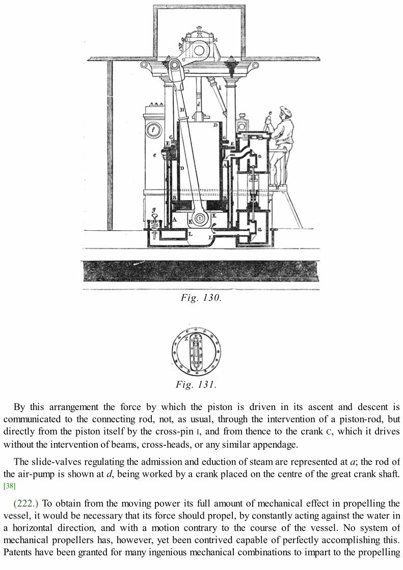
Fig. 130.
Fig. 131.
By this arrangement the force by which the piston is driven in its ascent and descent iscommunicated to the connecting rod, not, as usual, through the intervention of a piston-rod, butdirectly from the piston itself by the cross-pin I, and from thence to the crank C, which it driveswithout the intervention of beams, cross-heads, or any similar appendage.
The slide-valves regulating the admission and eduction of steam are represented at a; the rod ofthe air-pump is shown at d, being worked by a crank placed on the centre of the great crank shaft.[38]
(222.) To obtain from the moving power its full amount of mechanical effect in propelling thevessel, it would be necessary that its force should propel, by constantly acting against the water ina horizontal direction, and with a motion contrary to the course of the vessel. No system ofmechanical propellers has, however, yet been contrived capable of perfectly accomplishing this.Patents have been granted for many ingenious mechanical combinations to impart to the propelling

surfaces such angles as appeared to the respective contrivers most advantageous. In most of thesethe mechanical complexity has formed a fatal objection. No part of the machinery of a steam-vessel is so liable to become deranged at sea as the paddle-wheels; and, therefore, that simplicityof construction which is compatible with those repairs which are possible on such emergencies isquite essential for safe practical use.
Fig. 132.
The ordinary paddle-wheel, as has been already stated, is a wheel revolving upon a shaft drivenby the engine, and carrying upon its circumference a number of flat boards, called paddle-boards,which are secured by nuts and braces in a fixed position; and that position is such that the planes[Pg473] of the paddle-boards diverge nearly from the centre of the shaft on which the wheel turns.The consequence of this arrangement is that each paddle-board can only act in that direction whichis most advantageous for the propulsion of the vessel when it arrives near the lowest point of thewheel. In fig. 132. let O be the shaft on which the common paddle-wheel revolves; the position ofthe paddle-boards are represented at A, B, C, &c.; X, Y represents the water line, the course of thevessel being supposed to be from X to Y; the arrows represent the direction in which the paddle-wheel revolves. The wheel is immersed to the depth of the lowest paddle-board, since a lessdegree of immersion would render a portion of the surface of each paddle-board mechanicallyuseless. In the position A the whole force of the paddle-board is efficient for propelling the vessel;but as the paddle enters the water in the position H, its action upon the water, not being horizontal,is only partially effective for propulsion: a part of the force which drives the paddle is expendedin depressing the water, and the remainder in driving it contrary to the course of the vessel, and,therefore, by its re-action producing a certain propelling effect. The tendency, however, of thepaddle entering the water at H, is to form a hollow or trough, which the water, by its ordinaryproperty, has a continual tendency to fill up. After passing the lowest point A, as the paddleapproaches the position B, where it [Pg474] emerges from the water, its action again becomesoblique, a part only having a propelling effect, and the remainder having a tendency to raise thewater, and throw up a wave and spray behind the paddle-wheel. It is evident that the more deeplythe paddle-wheel becomes immersed, the greater will be the proportion of the propelling powerthus wasted in elevating and depressing the water; and if the wheel were immersed to its axis, thewhole force of the paddle-boards, on entering and leaving the water, would be lost, no part of ithaving a tendency to propel. If a still deeper immersion take place, the paddle-boards above the
axis would have a tendency to retard the course of the vessel. When the vessel is, therefore, inproper trim, the immersion should not exceed nor fall short of the depth of the lowest paddle; butfor various reasons it is impossible in practice to maintain this fixed immersion: the agitation ofthe surface of the sea, causing the vessel to roll, will necessarily produce a great variation in theimmersion of the paddle-wheels, one becoming frequently immersed to its axle, while the other israised altogether out of the water. Also the draught of water of the vessel is liable to change, by thevariation in her cargo; this will necessarily happen in steamers which take long voyages. Atstarting they are heavily laden with fuel, which as they proceed is gradually consumed, wherebythe vessel is lightened.
(223.) To remove this defect, and economise as much as possible the propelling effect of thepaddle-boards, it would be necessary so to construct them that they may enter and leave the wateredgeways, or as nearly so as possible; such an arrangement would be, in effect, equivalent to theprocess called feathering, as applied to oars. Any mechanism which would perfectly accomplishthis would cause the paddles to work in almost perfect silence, and would very nearly remove theinconvenient and injurious vibration which is produced by the action of the common paddles. Butthe construction of feathering paddles is attended with great difficulty, under the peculiarcircumstances in which such wheels work. Any mechanism so complex that it could not be easilyrepaired when deranged, with such engineering implements and skill [Pg475] as can be obtained atsea, would be attended with great objections; and the efficiency of its propelling action would notcompensate for the dangers which must attend upon the helpless state of a steamer, deprived of herpropelling agents.
Feathering paddle-boards must necessarily have a motion independently of the motion of thewheel, since any fixed position which could be given to them, though it might be most favourableto their action in one position would not be so in their whole course through the water. Thus thepaddle-board when at the lowest point should be in a vertical position, or so placed that its plane,if continued upwards, would pass through the axis of the wheel. In other positions, however, as itpasses through the water, it should present its upper edge, not towards the axle of the wheel, buttowards a point above the highest point of the wheel. The precise point to which the edge of thepaddle-board should be directed is capable of mathematical determination. But it will varyaccording to circumstances, which depend on the motion of the vessel. The progressive motion ofthe vessel, independently of the wind or current, must obviously be slower than the motion of thepaddle-boards round the axle of the wheel; since it is by the difference of these velocities that there-action of the water is produced by which the vessel is propelled. The proportion, however,between the progressive speed of the vessel and the rotative speed of the paddle-boards is notfixed: it will vary with the shape and structure of the vessel, and with its depth of immersion;nevertheless it is upon this proportion that the manner in which the paddle-boards should shift theirposition must be determined. If the progressive speed of the vessel were nearly equal to therotative speed of the paddle-boards, the latter should so shift their position that their upper edgesshould be presented to a point very little above the highest point of the wheel. This is a state ofthings which could only take place in the case of a steamer of a small draught of water, shallop-shaped, and so constructed as to suffer little resistance from the fluid. On the other hand, thegreater the depth of immersion, and the less fine the lines of the [Pg476] vessel, the greater will be theresistance in passing through the water, and the greater will be the proportion which the rotativespeed of the paddle-boards will bear to the progressive speed of the vessel. In this latter case theindependent motion of the paddle-boards should be such that their edges, while in the water, shall

be presented towards a point considerably above the highest point of the paddle-wheel.
A vast number of ingenious mechanical contrivances have been invented and patented foraccomplishing the object just explained. Some of these have failed from the circumstance of theirinventors not clearly understanding what precise motion it was necessary to impart to the paddle-board: others have failed from the complexity of the mechanism by which the desired effect wasproduced.
(224.) In the year 1829 a patent was granted to Elijah Galloway for a paddle-wheel withmovable paddles, which patent was purchased by Mr. William Morgan, who made variousalterations in the mechanism, not very materially departing from the principle of the invention.
Fig. 133.
This paddle-wheel is represented in fig. 133. The contrivance may be shortly stated to consist incausing the wheel which bears the paddles to revolve on one centre, and the radial arms whichmove the paddles to revolve on another centre. Let A B C D E F G H I K L be the polygonalcircumference of the paddle-wheel, formed of straight bars, securely connected together at theextremities of the spokes or radii of the wheel which turns on the shaft which is worked by theengine; the centre of this wheel being at O. So far this wheel is similar to the common paddle-wheel; but the paddle-boards are not, as in the common wheel, fixed at A B C, &c., so as to bealways directed to the centre O, but are so placed that they are capable of turning on axles whichare always horizontal, so that they can take any angle with respect to the water which may be givento them. From the centres, or the line joining the pivots on which these paddle-boards turn, thereproceed short arms K, firmly fixed to the paddle-boards at an angle of about 120°. On a motiongiven to this arm K, it will therefore give a corresponding angular motion to the paddle-board, soas to make it turn on its pivots. At [Pg477] the extremities of the several arms marked K is a pin orpivot, to which the extremities of the radial arms L are severally attached, so that the angle

between each radial arm L and the short paddle-arm K is capable of being changed by any motionimparted to L; the radial arms are connected at the other end with a centre, round which they arecapable of revolving. Now, since the points A B C, &c., which are the pivots on which the paddle-boards turn, are moved in the circumference of a circle, of which the centre is O, they are always atthe same distance from that point; consequently they will continually vary their distance from theother centre P. Thus, when a paddle-board arrives at that point of its revolution at which the centreround which it revolves lies precisely between it and the centre O, its distance from the formercentre is less than in any other position. As it departs from that point, its distance from that centregradually increases until it arrives at the opposite point of its revolution, where the centre O isexactly between it and the former centre; then the distance of the paddle-board from the formercentre is greatest. [Pg478] This constant change of distance between each paddle-board and the centreP is accommodated by the variation of the angle between the radial arm L and the short paddle-board arm K; as the paddle-board approaches the centre P this gradually diminishes; and as thedistance of the paddle-board increases, the angle is likewise augmented. This change in themagnitude of the angle, which thus accommodates the varying position of the paddle-board withrespect to the centre P, will be observed in the figure. The paddle-board D is nearest to P; and itwill be observed that the angle contained between L and K is there very acute; at E the anglebetween L and K increases, but is still acute; at G it increases to a right angle; at H it becomesobtuse; and at K, where it is most distant from the centre P, it becomes most obtuse. It againdiminishes at K, and becomes a right angle between A and B. Now this continual shifting of thedirection of the short arm K is necessarily accompanied by an equivalent change of position in thepaddle-board to which it is attached; and the position of the second centre P is, or may be, soadjusted that this paddle-board, as it enters the water and emerges from it, shall be such as shall bemost advantageous for propelling the vessel, and therefore attended with less of that vibrationwhich arises chiefly from the alternate depression and elevation of the water, owing to the obliqueaction of the paddle-boards.
(225.) In the year 1833, Mr. Field, of the firm of Maudslay and Field, constructed a paddle-wheel with fixed paddle-boards, but each board being divided into several narrow slips arrangedone a little behind the other, as represented in fig. 134. These divided boards he proposed toarrange in such cycloidal curves that they must all enter the water at the same place in immediatesuccession, avoiding the shock produced by the entrance of the common board. These split paddle-boards are as efficient in propelling when at the lowest point as the common paddle-boards, andwhen they emerge the water escapes simultaneously from each narrow board, and is not thrown up,as is the case with common paddle-boards.[39]

Fig. 134.
[Pg479] The theoretical effect of this wheel is the same as that of the common wheel, andexperience alone, the result of which has not yet been obtained, can prove its efficiency. Thenumber of bars, or separate parts into which each paddle-board is divided, has been very various.When first introduced by Mr. Galloway each board was divided into six or seven parts: this wassubsequently reduced, and in the more recent wheels of this form constructed for the governmentvessels the paddle-boards consist only of two parts, coming as near to the common wheel as ispossible, without altogether abandoning the principle of the split paddle.
(226.) To obtain an approximate estimate of the extent to which steam-power is applicable tolong sea-voyages, it would be necessary to investigate the mutual relation which, in the existingstate of this application of steam-power, exists between the capacity or tonnage of the vessel, themagnitude, weight, and power, of the machinery, the available stowage for fuel, and the averagespeed attainable in all [Pg480] weathers, as well as the general purposes to which the vessel is to beappropriated, whether for the transport of goods or merchandise, or merely for despatches andpassengers, or for both of these combined. That portion of the capacity of the vessel which isappropriated to the moving power consists of the space occupied by the machinery and the fuel.The distribution of it between these must mainly depend on the length of the voyage which thevessel must make without receiving a fresh supply of coals. If the trips be short, and frequentrelays of fuel can be obtained, then the space allotted to the machinery may bear a greaterproportion to that assigned to the fuel; but in proportion as each uninterrupted stage of the voyageis increased, a greater stock of coals will be necessary, and a proportionally less space left for themachinery. Other things being the same, therefore, steam-vessels intended for long sea-voyagesmust be less powerful in proportion to their tonnage.
It will be apparent that every improvement which takes place in the application of the steam-engine to navigation will modify all these data on which such an investigation must depend. Everyincreased efficiency of fuel, from whatever cause it may be derived, will either increase the usefultonnage of the vessel, or increase the length of the voyage of which it is capable. Variousimprovements have been and are still in progress, by which this efficiency has undergone continualaugmentation, and voyages may now be accomplished with moderate economy and profit, to whicha few years since marine engines could not be applied with permanent advantage. The averagespeed of steam-vessels has also undergone a gradual increase by such improvements. During thefour years ending June, 1834, it was found that the average rate of steaming obtained from fifty-onevoyages made by the Admiralty steamers between Falmouth and Corfu, exclusive of stoppages,was seven miles and a quarter an hour direct distance between port and port. The vessels whichperformed this voyage varied from 350 to 700 tons measured burden, and were provided withengines varying from 100 to 200 horse-power, with stowage for coals varying from 80 to 240 tons.The proportion of the power to the [Pg481] tonnage varied from one horse to three tons to one horseto four tons. Thus the MESSENGER had a power of 200 horses and measured 730 tons; the FLAMER
had a power of 120 horses, and measured 500 tons; the COLUMBIA had a power of 120 horses, andmeasured 360 tons. In general it may be assumed that for the shortest class of trips, such as those ofthe Channel steamers, the proportion of the power to the tonnage should be about one horse forevery two tons; but for the longer class of voyages, the proportion of power to tonnage should beabout one horse-power to from three to four tons measured tonnage. These data, however, must bereceived as very rough approximations, subject to considerable modifications in their applicationto particular vessels. We have already stated that the nominal horse-power is itself extremelyindefinite; and if, as is now customary in the longer class of voyages, the steam be workedexpansively, then the nominal power almost ceases to have any definite relation to the actualperformance of the vessel. It is usual to calculate the horse-power by assuming a uniform pressureof steam upon the piston, and, consequently, by excluding the consideration of the effect ofexpansion. The most certain test of the amount of mechanical power exerted by the machinerywould be obtained from the quantity of water actually transmitted in the form of steam from theboiler to the cylinder. But the effect of this would also be influenced by the extent to which theexpansive principle has been brought into operation.

From the reported performances of the larger class of steam-ships within the last few years, itwould appear that the average speed has been increased since the estimate above mentioned,which was obtained in 1834; and on comparing the consumption of fuel with the actualperformance, it would appear that the efficiency of fuel has also been considerably augmented. Noextensive course of accurate experiments or observations have, however, been obtained fromwhich correct inferences may be drawn of the probable limits to which steam-navigation, in itspresent state, is capable of being extended. The jealousy of rival companies has obstructed theinquiries of those who, solicitous more [Pg482] for the general advancement of the art than for thesuccess of individual enterprises, have directed their attention to this question; and it is hardly tobe expected that sufficiently correct and extensive data can be obtained for this purpose.
(227.) Increased facility in the extension and application of steam-navigation is expected toarise from the substitution of iron for wood, in the construction of vessels. Hitherto iron steamershave been chiefly confined to river-navigation; but there appears no sufficient reason why their useshould be thus limited. For sea-voyages they offer many advantages; they are not half the weight ofvessels of equal tonnage constructed of wood; and, consequently, with the same tonnage they willhave less draught of water, and therefore less resistance to the propelling power; or, with the samedraught of water and the same resistance, they will carry a proportionally heavier cargo. Thenature of their material renders them more stiff and unyielding than timber; and they do not sufferthat effect which is called hogging, which arises from a slight alteration which takes place in thefigure of a timber vessel in rolling, accompanied by an alternate opening and closing of the seams.Iron vessels have the further advantage of being more proof against fracture upon rocks. If a timbervessel strike, a plank is broken, and a chasm opened in her many times greater than the point ofrock which produces the concussion. If an iron vessel strike, she will either merely receive adinge, or be pierced by a hole equal in size to the point of rock which she encounters. Someexamples of the strength of iron vessels were given by Mr. Macgregor Laird, in his evidencebefore the Committee of the Commons on Steam Navigation, among which the following may bementioned:—An iron vessel, called the ALBURKAH, in one of their experimental trials got aground,and lay upon her anchor: in a wooden vessel the anchor would probably have pierced her bottom;in this case, however, the bottom was only dinged. An iron vessel, built for the Irish InlandNavigation Company, was being towed across Lough Derg in a gale of wind, when the towing ropebroke, and she was driven upon rocks, on which she bumped for a considerable time [Pg483] withoutany injury. A wooden vessel would in this case have gone to pieces. A further advantage of ironvessels (which in warm climates is deserving of consideration) is their greater coolness andperfect freedom from vermin.
Iron steam-vessels on a very large scale are now in preparation in the ports of Liverpool andBristol, intended for long sea-voyages. The largest vessel of this description which has yet beenprojected is stated to be in preparation for the voyage between Bristol and New York, by thecompany who have established the steam-ship called the Great Western, plying between theseplaces.
Several projects for the extension of steam-navigation to voyages of considerable length havelately been entertained both by the public and by the legislature, and have imparted to everyattempt to improve steam-navigation increased interest. A committee of the House of Commonscollected evidence and made a report in the last session in favour of an experiment to establish aline of steam-communication between Great Britain and India. Two routes have been suggested by

the committee, each being a continuation of the line of Admiralty steam-packets alreadyestablished to Malta and the Ionian Isles. One of the routes proposed is through Egypt, the RedSea, and across the Indian Ocean to Bombay, or some of the other presidencies; the other acrossthe north part of Syria to the banks of the Euphrates, by that river to the Persian Gulf, and fromthence to Bombay. Each of these routes will be attended with peculiar difficulties, and in both along sea-voyage will be encountered.
In the route by the Red Sea it is proposed to establish steamers between Malta and Alexandria(eight hundred and sixty miles). A steamer of four hundred tons' burden and one hundred horse-power would perform this voyage, upon an average of all weathers incident to the situation, infrom five to six days, consuming ten tons of coal per day. But it is probable that it might be foundmore advantageous to establish a higher ratio between the power and the tonnage. FromAlexandria the transit might be effected by land across the isthmus to Suez—a journey of from fourto five days—by caravan and camels; or the transit might be made either [Pg484] by land or waterfrom Alexandria to Cairo, a distance of one hundred and seventy-three miles; and from Cairo toSuez, ninety-three miles, across the desert, in about five days. At Suez would be a station forsteamers, and the Red Sea would be traversed in three runs or more. If necessary, stations forcoals might be established at Cosseir, Judda, Mocha, and finally at Aden or at Socatra—an islandimmediately beyond the mouth of the Red Sea, in the Indian Ocean; the run from Suez to Cosseirwould be three hundred miles—somewhat more than twice the distance from Liverpool to Dublin.From Cosseir to Judda, four hundred and fifty miles; from Judda to Mocha, five hundred andseventeen miles; and from Mocha to Socatra, six hundred and thirty-two miles. It is evident that allthis would, without difficulty, in the most unfavourable weather, fall within the present powers ofsteam-navigation. If the terminus of the passage be Bombay, the run from Socatra to Bombay willbe twelve hundred miles, which would be from six to eight days' steaming. The whole passagefrom Alexandria to Bombay, allowing three days for delay between Suez and Bombay, would betwenty-six days: the time from Bombay to Malta would therefore be about thirty-three days; andadding fourteen days to this for the transit from Malta to England, we should have a total of forty-seven days from London to Bombay, or about seven weeks.
If the terminus proposed were Calcutta, the course from Socatra would be one thousand twohundred and fifty miles south-east to the Maldives, where a station for coals would be established.This distance would be equal to that from Socatra to Bombay. From the Maldives, a run of fourhundred miles would reach the southern point of Ceylon, called the Point de Galle, which is thebest harbour (Bombay excepted) in British India: from the Point de Galle, a run of six hundredmiles will reach Madras, and from Madras to Calcutta would be a run of about six hundred miles.The voyage from London to Calcutta would be performed in about sixty days.
At a certain season of the year there exists a powerful physical opponent to the transit from Indiato Suez: from [Pg485] the middle of June until the end of September, the south-west monsoon blowswith unabated force across the Indian Ocean, and more particularly between Socatra and Bombay.This wind is so violent as to leave it barely possible for the most powerful steam-packet to makehead against it, and the voyage could not be accomplished without serious wear and tear upon thevessels during these months.
The attention of parliament has therefore been directed to another line of communication, notliable to this difficulty: it is proposed to establish a line of steamers from Bombay through thePersian Gulf to the Euphrates.

The run from Bombay to a place called Muscat, on the southern shore of the gulf, would be eighthundred and forty miles in a north-west direction, and therefore not opposed to the south-westmonsoon. From Muscat to Bassidore, a point upon the northern coast of the strait at the mouth ofthe Persian Gulf, would be a run of two hundred and fifty-five miles; from Bassidore to Bushire,another point on the eastern coast of the Persian Gulf, would be a run of three hundred miles; andfrom Bushire to the mouth of the Euphrates, would be one hundred and twenty miles. It is evidentthat the longest of these runs would offer no more difficulty than the passage from Malta toAlexandria. From Bussora, near the mouth of the Euphrates, to Bir, a town upon its left bank nearAleppo, would be one thousand one hundred and forty-three miles, throughout which there are nophysical obstacles to the river-navigation which may not be overcome. Some difficulties arisefrom the wild and savage character of the tribes who occupy its banks. It is, however, thought thatby proper measures, and securing the co-operation of the pacha of Egypt, any serious obstructionfrom this cause may be removed. From Bir, by Aleppo, to Scanderoon, a port upon theMediterranean, opposite Cyprus, is a land-journey, said to be attended with some difficulty, but notof great length; and from Scanderoon to Malta is about the same distance as between the latterplace and Alexandria. It is calculated that the time from London to Bombay by the Euphrates—supposing the passage to be successfully [Pg486] established—would be a few days shorter than byEgypt and the Red Sea.
Whichever of these courses may be adopted, it is clear that the difficulties, so far as the powersof the steam engine are concerned, lie in the one case between Socatra and Bombay, or betweenSocatra and the Maldives, and in the other case between Bombay and Muscat. This, however, hasalready been encountered and overcome on four several voyages by the HUGH LINDSAY steamerfrom Bombay to Suez: that vessel encountered a still longer run on these several trips, by going,not to Socatra, but to Aden, a point on the coast of Arabia, near the Straits of Babel Mandeb, beinga run of one thousand six hundred and forty-one miles, which she performed in ten days andnineteen hours. The same trip has since been repeatedly made by other steamers; and, in thepresent improved state of steam navigation, no insurmountable obstacles are opposed to theirpassage.

FOOTNOTES:[35] This cut is taken from the plate of the engine of the Red Rover, manufactured by Boulton and Watt, given in the last
edition of Tredgold on the Steam Engine.
[36] Appendix I., on Marine Boilers, by J. Dinnen; Tredgold on the Steam Engine, second edition.
[37] Tredgold on the Steam Engine, Appendix, I. p. 171.
[38] Engines on a very large scale constructed upon this principle are said to be in process of construction for an ironsteam-vessel of great tonnage, which is in preparation for the New York passage. It is said that the cylinders ofthese engines will be one hundred and twenty inches in diameter.
[39] A patent was subsequently taken out for these by Mr. Galloway. Mr. Field did not persevere in its use at the time heinvented it. It has, however, been more generally adopted since the date of Galloway's patent.

CHAP. XIV.
AMERICAN STEAM NAVIGATION.[Pg487]
TOC INX
STEAM NAVIGATION FIRST ESTABLISHED IN AMERICA.—CIRCUMSTANCES WHICH LED TO IT.—FITCH ANDRUMSEY.—STEVENS OF HOBOKEN.—LIVINGSTONE AND FULTON.—EXPERIMENTS ON THE SEINE.—FULTON'S FIRST BOAT.—THE HUDSON NAVIGATED BY STEAM.—EXTENSION AND IMPROVEMENT OFRIVER NAVIGATION.—SPEED OF AMERICAN STEAMERS.—DIFFERENCE BETWEEN THEM ANDEUROPEAN STEAMERS.—SEA-GOING AMERICAN STEAMERS.—AMERICAN PADDLE-WHEELS.—LAKESTEAMERS.—THE MISSISIPPI AND ITS TRIBUTARIES.—STEAMERS NAVIGATING IT.—THEIR STRUCTUREAND MACHINERY.—NEW ORLEANS HARBOUR.—STEAM TUGS.
(228.) The credit of having afforded the first practical solution of the problem to apply the steamengine to the propulsion of ships, undoubtedly belongs to the people of the United States ofAmerica. The geographical character of their vast country, not less than the sanguine andenterprising spirit of the nation, contributed to this. A coast of four thousand miles in extent,stretching from the Gulf of St. Lawrence to the embouchures of the Mississippi, indented and [Pg488]
serrated in every part with natural harbours and sheltered bays, and fringed with islands formingsounds—capes, and promontories enclosing arms of the sea, in which the waters are free from theroll of the ocean, and take the placid character of lakes,—rivers of imposing magnitude, navigablefor vessels of the largest class, for many hundreds and in some instances for many thousands ofmiles, affording access to the innermost population of an empire, whose area vastly exceeds thewhole European continent,—chains of lakes composed of the most extensive bodies of fresh waterin the known world,—and this extensive continent peopled by races carrying with them the habitsand feelings together with much of the skill and knowledge of the most civilized parts of the globe,endowed also with that inextinguishable spirit of enterprise which ever belongs to an emigrantpeople,—form a combination of circumstances more than sufficient to account for the fact of thisnation snatching from England, the parent of the steam engine, the honour of first bringing intopractical operation one of the most important—if indeed it be not altogether the most important—of the many applications of that machine to the uses of life.
The circumstances which rendered these extensive tracts of inland and coast navigationeminently suited to the application of steam power, formed so many obstructions and difficulties tothe application of other more ordinary means of locomotion on water. The sheltered bays andsounds which offered a smooth and undisturbed surface to the action of the infant steamer arguedthe absence of that element which gave effect to the sails and rigging of the wind-propelled ship,and the rapid currents of the gigantic streams formed by the drainage of this great continent, thoughfacilitating access to the coast, rendered the oar powerless in the ascent.
(229.) The first great discovery of Watt had scarcely been realized in practice by theconstruction of the single-acting steam-engine, when the speculative and enterprising Americansconceived the project of applying it as a moving power in their inland navigation. So early as theyear 1783 [Pg489] Fitch and Rumsey made attempts to apply the single-acting engine to thepropulsion of vessels, and their failure is said to have arisen more from the inherent defects of thatmachine in reference to this application of it, than from any want of ingenuity or mechanical skill
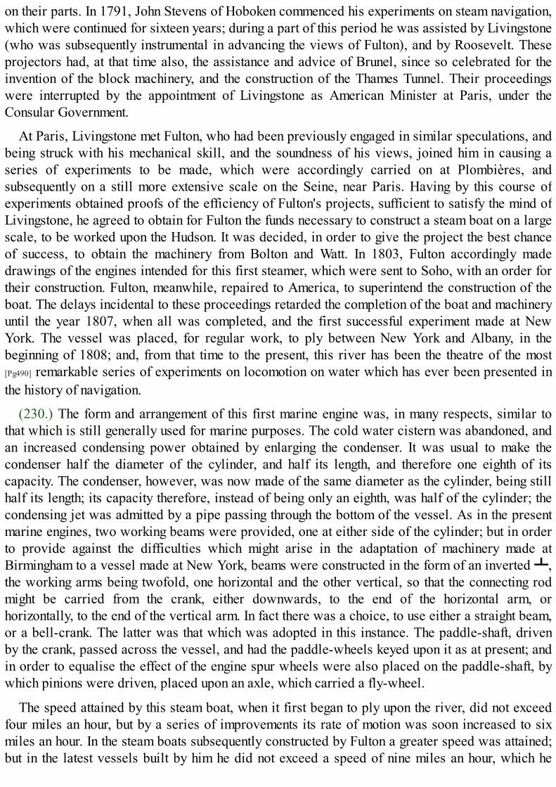
on their parts. In 1791, John Stevens of Hoboken commenced his experiments on steam navigation,which were continued for sixteen years; during a part of this period he was assisted by Livingstone(who was subsequently instrumental in advancing the views of Fulton), and by Roosevelt. Theseprojectors had, at that time also, the assistance and advice of Brunel, since so celebrated for theinvention of the block machinery, and the construction of the Thames Tunnel. Their proceedingswere interrupted by the appointment of Livingstone as American Minister at Paris, under theConsular Government.
At Paris, Livingstone met Fulton, who had been previously engaged in similar speculations, andbeing struck with his mechanical skill, and the soundness of his views, joined him in causing aseries of experiments to be made, which were accordingly carried on at Plombières, andsubsequently on a still more extensive scale on the Seine, near Paris. Having by this course ofexperiments obtained proofs of the efficiency of Fulton's projects, sufficient to satisfy the mind ofLivingstone, he agreed to obtain for Fulton the funds necessary to construct a steam boat on a largescale, to be worked upon the Hudson. It was decided, in order to give the project the best chanceof success, to obtain the machinery from Bolton and Watt. In 1803, Fulton accordingly madedrawings of the engines intended for this first steamer, which were sent to Soho, with an order fortheir construction. Fulton, meanwhile, repaired to America, to superintend the construction of theboat. The delays incidental to these proceedings retarded the completion of the boat and machineryuntil the year 1807, when all was completed, and the first successful experiment made at NewYork. The vessel was placed, for regular work, to ply between New York and Albany, in thebeginning of 1808; and, from that time to the present, this river has been the theatre of the most[Pg490] remarkable series of experiments on locomotion on water which has ever been presented inthe history of navigation.
(230.) The form and arrangement of this first marine engine was, in many respects, similar tothat which is still generally used for marine purposes. The cold water cistern was abandoned, andan increased condensing power obtained by enlarging the condenser. It was usual to make thecondenser half the diameter of the cylinder, and half its length, and therefore one eighth of itscapacity. The condenser, however, was now made of the same diameter as the cylinder, being stillhalf its length; its capacity therefore, instead of being only an eighth, was half of the cylinder; thecondensing jet was admitted by a pipe passing through the bottom of the vessel. As in the presentmarine engines, two working beams were provided, one at either side of the cylinder; but in orderto provide against the difficulties which might arise in the adaptation of machinery made atBirmingham to a vessel made at New York, beams were constructed in the form of an inverted ┻,the working arms being twofold, one horizontal and the other vertical, so that the connecting rodmight be carried from the crank, either downwards, to the end of the horizontal arm, orhorizontally, to the end of the vertical arm. In fact there was a choice, to use either a straight beam,or a bell-crank. The latter was that which was adopted in this instance. The paddle-shaft, drivenby the crank, passed across the vessel, and had the paddle-wheels keyed upon it as at present; andin order to equalise the effect of the engine spur wheels were also placed on the paddle-shaft, bywhich pinions were driven, placed upon an axle, which carried a fly-wheel.
The speed attained by this steam boat, when it first began to ply upon the river, did not exceedfour miles an hour, but by a series of improvements its rate of motion was soon increased to sixmiles an hour. In the steam boats subsequently constructed by Fulton a greater speed was attained;but in the latest vessels built by him he did not exceed a speed of nine miles an hour, which he

considered to be the greatest that could be advantageously obtained.
While Fulton was making his plans, and engaged in the [Pg491] construction of his first boat, Mr.Stevens of Hoboken, already mentioned, was engaged in a like project, and completed a vessel, tobe propelled by a steam engine, within a few weeks after the first successful voyage of Fulton.Stevens was likewise completely successful; but the exclusive privilege of navigating the Hudsonby steam having been granted to Fulton by an act of Congress, Stevens was compelled to selectanother theatre for his operations, and he accordingly sent his steam boat by sea to Philadelphia, tonavigate the Delaware, thus securing for himself the honour of having made the first sea voyage bysteam.
Fulton did not long retain the monopoly of the steam navigation of the Hudson. Fortunately forthe progress of steam navigation, the act conferring upon him that privilege was declaredunconstitutional; and the navigation of that noble river was thrown open to the spirit and enterpriseof American genius. The number of passengers conveyed upon it became enormous beyond allprecedent, and inducements of the strongest kind were accordingly held out to the improvement ofits navigation. The distance between New York and Albany, ascertained by a late survey to be onehundred and twenty-five geographical miles by water, had been performed by Fulton's boatsoccasionally in fifteen or sixteen hours, being at the rate of about eight miles an hour, includingstoppages. It became a great object to increase the speed of this trip, so that it might at all times ofthe year be performed between sunrise and sunset. Robert L. Stevens, the son of the person of thatname already mentioned, immediately after the abolition of Fulton's monopoly, placed on the rivera vessel which had been built for the Delaware, which easily performed the passage in twelvehours, being at the rate of nearly ten and a half geographical miles an hour. By this increase ofspeed the improved boats so entirely monopolised the day work upon the river, that the formersteamers were either converted into steam tugs to draw barges laden with goods, or used for nighttrips between New York and Albany. In the night trips the saving of one or two hours wasimmaterial, it being sufficient that the vessel which left the one port at night should reach the otherin the morning. [Pg492]
The river Hudson rises near Lake Champlain, the easternmost of the great chain of lakes orinland seas which extend from east to west across the northern boundary of the United States. Theriver follows nearly a straight course southwards for two hundred and fifty miles, and emptiesitself into the sea at New York. The influence of the tide is felt as far as Albany, above which thestream begins to contract. Although this river in magnitude and extent is by no means equal toseveral others which intersect the States, it is nevertheless rendered an object of great interest byreason of the importance and extent of its trade. The produce of the state of New York and that ofthe banks of the great Lakes Ontario and Erie are transported by it to the capital; and one of themost extensive and populous districts of the United States is supplied with the necessary importsby its waters. A large fleet of vessels is constantly engaged in its navigation; nor is the tardy butpicturesque sailing vessel as yet excluded by the more rapid steamers. The current of the Hudsonis said to average nearly three miles an hour; but as the ebb and flow of the tide are felt as far asAlbany, the passage of the steamers between that place and New York may be regarded as equallyaffected by currents in both directions, or nearly so. The passage therefore, whether in ascendingor descending the river, is made nearly in the same time.
(231.) The prevalence of smooth water navigation, whether on the surfaces of rivers or insheltered bays and sounds, has invested the problem of steam navigation in America with

conditions so entirely distinct and different from those under which the same problem presentsitself to the European engineer, that any comparison of the performance of vessels, whether withregard to speed or the absorption of power in the two cases, must be utterly fallacious. In Europe asteamer is almost invariably a vessel designed to encounter the agitated surface of an open sea,and is accordingly constructed upon principles of suitable strength and stability. It is likewisesupplied with rigging and with sails, to be used in aid of the mechanical power, and manned andcommanded by experienced seamen; in fact, it is a combination of a nautical and mechanicalstructure. In America, on the other hand, [Pg493] with the exception of the vessels which navigate thegreat northern lakes, the steamers are structures exclusively mechanical, being designed for smoothwater. They require no other strength or stability than that which is sufficient to enable them tofloat and to bear a progressive motion through the water. Their mould is conceived with anexclusive view to speed; they are therefore slender and weak in their build, of great length inproportion to their width, and having a very small draught of water. In fact, they approach in theirform to that of a Thames wherry on a very large scale.
The position and form of the machinery is likewise affected by these conditions. Without thenecessity of being protected from a rough sea, it is placed on the deck in an elevated position. Thecylinders of large diameter and short stroke invariably used in Europe are unknown in America,and the proportions are reversed, a small diameter and stroke of great length being invariablyadopted. It is rarely that two engines are used. A single engine, placed in the centre of the deck,with a cylinder from forty to sixty inches' diameter, and from eight to ten foot stroke, drivespaddle-wheels from twenty-one to twenty-five feet in diameter, producing from twenty-five tothirty revolutions per minute. The great magnitude of the paddle-wheels and the velocity impartedto them enable them to perform the office of fly-wheels, and to carry the engine round its centres,not however without a perceptible inequality of motion, which gives to the American steamer aneffect like that of a row boat advancing by starts with each stroke of the piston. The length ofstroke adopted in these engines enables them to apply with great effect the expansive principle,which is almost universally used, the steam being generally cut off at half stroke.
The steamers which navigate the Hudson are vessels of considerable magnitude, splendidlyfitted up for the accommodation of passengers; they vary from one hundred and eighty to twohundred and forty feet in length, and from twenty to thirty feet in width of beam. In the followingtable is given the particulars of nine steamers plying on this river, taken from [Pg494] the work of Mr.Stevenson, and from the paper of Mr. Renwick, inserted in the last edition of Tredgold:—
Names. Length ofDeck.
Breadth ofBeam.
Draft ofWater.
Drain ofWheel.
Ft. Ft. Ft. Ft.DewitClinton 230 28 5·5 21Champlain 180 27 5·5 22Erie 180 27 5·5 22NorthAmerica 200 30 5 21Independence 148 26 -- --Albany 212 26 -- 24·5Swallow 233 22·5 3·75 24Rochester 200 25 3·75 23·5Utica 200 21 3·5 22

Names. Length ofPaddles.
Depth ofPaddles.
Number ofEngines.
Drain ofCylinder.
Ft. In. In.DewitClinton 13·7 36 1 65Champlain 15 34 2 44Erie 15 34 2 44NorthAmerica 13 30 2 44·5Independence -- -- 1 44Albany 14 30 1 65Swallow 11 30 1 46Rochester 10 24 1 43Utica 9·5 24 1 39
Names. Length ofStroke.
Number ofRev.
Part of Stroke at which it iscut off.
Ft.DewitClinton 10 29 3⁄4
Champlain 10 27·5 1⁄2
Erie 10 27·5 1⁄2NorthAmerica 8 24 1⁄2Independence 10Albany -- 19Swallow -- 27Rochester 10 28Utica 10
None of these vessels have either masts or rigging, and consequently never derive anypropelling power except from the engines: they are neither manned nor commanded by personshaving any knowledge of navigation: the works that are visible above their decks are the beam andframing of the engine, and the chimneys.
The engines used for steamers on the Hudson, and other great rivers and bays on the easterncoast of America, are most commonly condensing engines, but they nevertheless work with steamof very high pressure, being seldom less than twenty-five pounds per square inch, and sometimesas much as fifty. By reference to the preceding table it will be seen, that the velocity of the pistongreatly exceeds the limit generally observed in Europe. It is customary in European marine enginesto limit the speed of the piston to about two hundred and twenty feet per minute. Even the piston ofa locomotive engine does not much exceed the rate of three hundred feet per minute. In theAmerican steamers, however, the pistons commonly move at the rate of from five to six hundredfeet per minute, while the circumference of the paddle-wheels are driven at the rate of from twentyto twenty-two miles an hour. [Pg495]

Fig. 135.
The hulls of these boats are formed with a perfectly flat bottom and perpendicular sides,rounded at the angles, as represented in fig. 135. At the bow, or cutwater, they are made verysharp, and the deck projects to a great distance over the sides. The weight of the machinery isdistributed over an extensive surface of the bottom of this feeble structure, by means of a frame-work of substantial carpentry to which it is attached.
At the height of from four to six feet above the water-line is placed the deck, which is aplatform, having the shape of a very elongated ellipse. The extremities of its longer axis aresupported by the sternpost and the cutwater, and its sides expand in gentle curves on either hand toa considerable distance beyond the limits of the hull; those parts of the deck thus overhanging thewater are called the wheel guards.
Beneath the first deck is the saloon, or dining-room, which also, as is usual in Europeansteamers, forms the gentlemen's sleeping-room. It usually extends from end to end of the vessel.The middle of the first deck is occupied by the engine, boilers, furnaces, and chimneys, of whichlatter there are generally two. Between the chimneys and the stern, above the first deck, isconstructed the ladies' cabin, which is covered by the second deck, called the promenade deck.The great length of these boats and the elevation of the cabins render it impossible for a steersmanat the stern to see ahead, and they are, consequently, steered from the bow; the wheel placed therecommunicating with the helm at the stern, by chains or rods carried along the sides of the boat.Until a recent period, the wheel was connected with the stern by ropes, but some fatal accidents,produced by fire, [Pg496] in which these ropes were burnt, and the steersman lost all power to guidethe vessel, caused metal rods or chains to be substituted.
(232.) The paddle-wheels universally used in American steam-boats are formed, as if by thecombination of two or more common paddle-wheels, placed one outside the other, on the sameaxle, but so that the paddle boards of each may have an intermediate position between those of theadjacent one, as represented in fig. 136.

Fig. 136.
The spokes, which are bolted to cast-iron flanges, are of wood. These flanges, to which they areso bolted, are keyed upon the paddle shaft. The outer extremities of the spokes are attached tocircular bands or hoops of iron, surrounding the wheel; and the paddle boards, which are formedof hard wood, are bolted to the spokes. The wheels thus constructed, sometimes consist of three,and not unfrequently four, independent circles of paddle boards, placed one beside the other, andso adjusted in their position, that the boards of no two divisions shall correspond.
The great magnitude of the paddle-wheels, and the circumstance of the navigation being carriedon, for the most part, in smooth water, have rendered unnecessary, in America, the adoption of anyof those expedients for neutralising the effects of the oblique action of the paddles, which havebeen tried, but hitherto with so little success, in Europe.
(233.) Sea-going steamers are not numerous in America, the chief of them being those which plybetween New York and Providence, and between New York and Charleston. These vessels,however, do not resemble the sea-going steamers of Europe as closely as might be expected; andto those who are accustomed to the latter, the sea-going [Pg497] steamers of America can hardly beregarded as safe means of transport.
In the following Table is given the dimensions of five of these vessels, all plying between NewYork and Providence:—
Names. Length ofDeck.
Breadth ofBeam.
Draft. Diameter ofWheel.
Ft. Ft. Ft. Ft.Providence 180 27 9 --Lexington 207 21 -- 23Narragansett 210 26 5 25Massachusetts 200 29·5 8·5 22Rhode Island 210 26 6·5 24
Names. Length ofPaddles.
Depth ofPaddles.
Number ofEngines.
Diameter ofCylinder.
Ft. In. In.Providence -- -- 1 10Lexington 9 30 1 11Narragansett 11 30 1 60Massachusetts 10 28 2 44

Rhode Island 11 30 1 11
Names. Length ofStroke.
Number ofRev.
Part of stroke at which strokeis cut off.
Ft.Providence 65Lexington 48 24
Narragansett 12 2 1⁄2Massachusetts 8 26Rhode Island 60 21
The Narragansett, the finest of these vessels, is built of oak, strengthened by diagonal straps orties of iron, by which her timbers are connected; she is driven by a condensing engine, and has twoboilers, exposing about three thousand square feet of surface to the fire. The steam is maintained ata pressure of from twenty to twenty-five lbs. per square inch: the cylinder is horizontal.
The cabins of these sea-boats are of great magnitude, and afford excellent accommodation forpassengers, containing generally four hundred berths. In the Massachusetts the chief cabin is onehundred and sixty feet long, twenty-two feet wide, and twelve feet in height, its vast extent beinguninterrupted by pillars or any other obstruction. "I have dined," says Mr. Stevenson, "with onehundred and seventy-five persons in this cabin, and, notwithstanding this numerous assembly, thetables, which were arranged in two parallel rows, extending from one end of the cabin to the other,were far from being fully occupied, the attendance was good, and every thing was conducted withperfect regularity and order. There are one hundred and twelve fixed berths ranged round thiscabin, and one hundred temporary berths can be erected in the middle of the floor: besides thesethere are sixty fixed berths in the ladies' cabin, and several temporary sleeping [Pg498] places can beerected in it also. The cabin of the Massachusetts is by no means the largest in the United States.Some steamers have cabins upwards of one hundred and seventy-five feet in length. Those largesaloons are lighted by Argand lamps, suspended from the ceiling, and their appearance, whenbrilliantly lighted up and filled with company, is very remarkable. The passengers generallyarrange themselves in parties at the numerous small tables into which the large tables areconverted after dinner, and engage in different amusements. The scene resembles much more thecoffee-room of some great hotel than the cabin of a floating vessel."
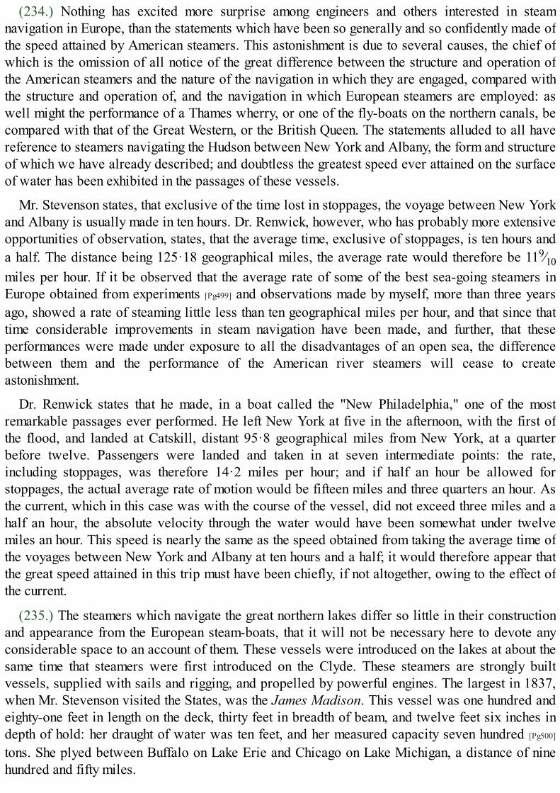
(234.) Nothing has excited more surprise among engineers and others interested in steamnavigation in Europe, than the statements which have been so generally and so confidently made ofthe speed attained by American steamers. This astonishment is due to several causes, the chief ofwhich is the omission of all notice of the great difference between the structure and operation ofthe American steamers and the nature of the navigation in which they are engaged, compared withthe structure and operation of, and the navigation in which European steamers are employed: aswell might the performance of a Thames wherry, or one of the fly-boats on the northern canals, becompared with that of the Great Western, or the British Queen. The statements alluded to all havereference to steamers navigating the Hudson between New York and Albany, the form and structureof which we have already described; and doubtless the greatest speed ever attained on the surfaceof water has been exhibited in the passages of these vessels.
Mr. Stevenson states, that exclusive of the time lost in stoppages, the voyage between New Yorkand Albany is usually made in ten hours. Dr. Renwick, however, who has probably more extensiveopportunities of observation, states, that the average time, exclusive of stoppages, is ten hours anda half. The distance being 125·18 geographical miles, the average rate would therefore be 119⁄10miles per hour. If it be observed that the average rate of some of the best sea-going steamers inEurope obtained from experiments [Pg499] and observations made by myself, more than three yearsago, showed a rate of steaming little less than ten geographical miles per hour, and that since thattime considerable improvements in steam navigation have been made, and further, that theseperformances were made under exposure to all the disadvantages of an open sea, the differencebetween them and the performance of the American river steamers will cease to createastonishment.
Dr. Renwick states that he made, in a boat called the "New Philadelphia," one of the mostremarkable passages ever performed. He left New York at five in the afternoon, with the first ofthe flood, and landed at Catskill, distant 95·8 geographical miles from New York, at a quarterbefore twelve. Passengers were landed and taken in at seven intermediate points: the rate,including stoppages, was therefore 14·2 miles per hour; and if half an hour be allowed forstoppages, the actual average rate of motion would be fifteen miles and three quarters an hour. Asthe current, which in this case was with the course of the vessel, did not exceed three miles and ahalf an hour, the absolute velocity through the water would have been somewhat under twelvemiles an hour. This speed is nearly the same as the speed obtained from taking the average time ofthe voyages between New York and Albany at ten hours and a half; it would therefore appear thatthe great speed attained in this trip must have been chiefly, if not altogether, owing to the effect ofthe current.
(235.) The steamers which navigate the great northern lakes differ so little in their constructionand appearance from the European steam-boats, that it will not be necessary here to devote anyconsiderable space to an account of them. These vessels were introduced on the lakes at about thesame time that steamers were first introduced on the Clyde. These steamers are strongly builtvessels, supplied with sails and rigging, and propelled by powerful engines. The largest in 1837,when Mr. Stevenson visited the States, was the James Madison. This vessel was one hundred andeighty-one feet in length on the deck, thirty feet in breadth of beam, and twelve feet six inches indepth of hold: her draught of water was ten feet, and her measured capacity seven hundred [Pg500]
tons. She plyed between Buffalo on Lake Erie and Chicago on Lake Michigan, a distance of ninehundred and fifty miles.

The severe storms and formidable sea encountered on the lakes render necessary for thenavigation, vessels in all respects as strong and powerful as those which navigate the open ocean.
(236.) By far the most remarkable and important of all the American rivers is the Mississippiand its tributaries. That part of the American continent which extends from the southern shores ofthe great northern lakes to the northern shores of the Gulf of Mexico, is watered by these greatstreams. The main stream of the Mississippi has its fountains in the tract of country lying north ofthe Illinois and east of Lake Michigan, in latitude forty-three degrees. At about latitude thirty-ninedegrees, a little north of St. Louis, it receives the waters of the Missouri, and further south, at thelatitude of thirty-seven degrees, the Ohio flows into it, after traversing five degrees of longitudeand four of latitude, and winding its way from the Alleghany range through several of the states,and forming a navigable communication with numerous important towns of the Union, amongwhich may be mentioned Pittsburg, Cincinnati, Frankfort, Lexington, and Louisville. The mainstream of the Mississippi, after receiving the waters of the Arkansas, and numerous other minortributaries, flows into the Gulf of Mexico by four mouths. The main stream of the Mississippi,independently of its tributaries, forms an unbroken course of inland navigation for a distance ofnearly two thousand three hundred miles. Its width, through a distance of one thousand one hundredmiles from its mouth, is not less than half a mile, and its average depth a hundred feet. The Ohio,its chief eastern tributary, flowing into it at a distance of about a thousand miles from its mouth,traverses also about the same extent of country, and is navigable throughout the whole of thatextent. This river also has several navigable tributaries of considerable extent, among which maybe mentioned the Muskingum, navigable for one hundred and twenty miles; the Miami, navigablefor seventy-five miles; the Scioto, navigable for one hundred and twenty [Pg501] miles; theTennessee, navigable for two hundred and fifty miles; the Cumberland, navigable for four hundredand forty miles; the Kentucky, navigable for one hundred and thirty miles; and the Green River,navigable for one hundred and fifty miles. The total length of the Ohio and its tributaries isestimated at above seven thousand miles.
(237.) Steam-boats were introduced on the Mississippi about the year 1812, the period of theirfirst introduction in Europe; and their increase has been rapid beyond all precedent. In the year1831 there were one hundred and ninety-eight steamers plying on its waters; and the number in1837 amounted to nearly four hundred. These vessels are built chiefly on the banks of the Ohio, atthe towns of Pittsburg and Cincinnati, at distances of about two thousand miles from the mouth ofthe river they are intended to navigate.
(238.) These steamers, which are decidedly inferior to those which navigate the eastern waters,are generally of a heavy build, fitted to carry goods as well as passengers, and vary from onehundred to seven hundred tons burthen. Their draught of water is also greater than that of theeastern river steamers—varying from six to eight feet. The hull, at about five feet from the waterline, is covered with a deck, under which is the hold, in which the heavy part of the cargo isstowed. About the middle of this deck the engines are placed, the boilers and furnaces occupying aspace nearer to the bow, near which two chimneys are placed. The fire-doors of the furnaces arepresented towards the bow, and exposed so as to increase the draught. That part of the first deckwhich extends from the machinery to the stern is the place allotted to the crew and the deckpassengers, and is described as being filthy and inconvenient in the extreme. A second deck isconstructed, which extends from the chimneys near the bow to the stern of the vessel. On this isformed the great cabin or saloon, which extends from the chimneys to within about thirty feet of the

stern, where it is divided by a partition from the ladies' cabin, which occupies the remainingspace. These principal cabins are surrounded by a gallery about three feet in width, from which, atconvenient [Pg502] places, an ascent is supplied by stairs to the highest deck, called the hurricane orpromenade deck.
(239.) The engines by which these boats are propelled are totally different from the machineryalready described as used in the eastern steamers. They are invariably non-condensing engines,worked by steam of extremely high pressure; the boilers are therefore tubular, and the cylinderssmall in diameter, but generally having a long stroke.
The pressure of steam used in these machines is such as is never used in European engines, evenwhen worked on railways. A pressure of one hundred pounds per inch is here consideredextremely moderate. The captain of one of these boats, plying between Pittsburg and St. Louis, toldMr. Stevenson that "under ordinary circumstances his safety valves were loaded with a pressureequal to one hundred and thirty-eight pounds per square inch, but that the steam was occasionallyraised as high as one hundred and fifty pounds to enable the vessel to pass parts of the river inwhich there is a strong current;" and he added, by way of consolation, that "this pressure wasnever exceeded except on extraordinary occasions!"
The dimensions and power of the Mississippi steamers may be collected from those of the St.Louis, a boat which was plying on that river in 1837. That vessel measured two hundred and fiftyfeet on deck, and had twenty-eight feet breadth of beam. Her draught of water was eight feet, andher measured capacity one thousand tons. She was propelled by two engines with thirty-inchcylinders, and ten feet stroke; the safety valve being loaded at one hundred pounds per square inch.
The paddle wheels of these vessels are attached to the paddle shaft, in such a manner as to bethrown into and out of gear, at discretion, by the engineer, so that the paddle shaft may revolvewithout driving the wheels: by this expedient the power of the engine is used to feed the boilerswhile the vessel stops at the several stations. The vessel is therefore stopped, not, as is usually thecase, by stopping the engines, but by throwing the wheels out of connection with the paddle shaft.The engines continue to work, but their [Pg503] power is expended in forcing water into the boiler.By this expedient the activity of the engines may, within practical limits, be varied with theresistance the vessel has to encounter. In working against a strong current, the feed may be cut offfrom the boilers, and the production of steam, and consequently the power of the engines, therebystimulated, while this suspension of the feed may be compensated at the next station.
The stoppages to take in goods and passengers, and for relays of fuel, are frequent. "The libertywhich they take with their vessels on these occasions," says Mr. Stevenson, "is somewhat amusing:I had a good example of this on board a large vessel, called the Ontario. She was steered close inshore amongst stones and stumps of trees, where she lay for some hours to take in goods: theadditional weight increased her draught of water, and caused her to heel a good deal; and when herengines were put in motion, she actually crawled into the deep water on her paddle wheels: thesteam had been got up to an enormous pressure to enable her to get off, and the volume of steamdischarged from the escapement pipe at every half stroke of the piston made a sharp sound almostlike the discharge of fire-arms, while every timber in the vessel seemed to tremble, and the wholestructure actually groaned under the shocks."
Besides the steamers used for the navigation of the Mississippi, innumerable steam tugs areconstantly employed in towing vessels between the port of New Orleans and the open sea of the

Gulf of Mexico. Before the invention of steam navigation, this southern capital of the United Stateslaboured under the disadvantage of possessing almost the only bad and inconvenient harbour in thevast range of coast by which the country is bounded. New Orleans lies at a distance of about onehundred miles from the Gulf of Mexico. The force of the stream, the frequency of shoals, and thewinding course of the channel rendered it scarcely possible for a sailing vessel to pass betweenthe port and the sea with the same wind. The anchorage was every where bad, and great difficultyand risk attended the mooring of large vessels to the banks. The steam engine has, however,overcome all [Pg504] these difficulties, and rendered the most objectionable harbour of the Union asafe and good seaport, perfectly easy of approach and of egress at all times; a small steam tug willtake in tow several large ships, and carry them with safety and expedition to the offing, where itwill dismiss them on their voyage, and take back vessels which may have arrived.
GREAT WESTERN OFF NEW YORK.

APPENDIX.
[Pg505]
TOC INX
On the Relation between the Temperature, Pressure, and Density of Common Steam.
There is a fixed relation between the temperature and pressure of common steam, which has not yetbeen ascertained by theory. Various empirical formulæ have been proposed to express it, derivedfrom tables of temperatures and corresponding pressures which have been founded on experimentsand completed by interpolation.
The following formula, proposed by M. Biot, represents with great accuracy the relationbetween the temperature and pressure of common steam, throughout all that part of thethermometric scale to which experiments have been extended.
Let
a = 5·96131330259
log. a1 = 0·82340688193 − 1
log. b1 = −·01309734295
log. a2 = 0·74110951837
log. b2 = −·00212510583
The relation between the temperature t with reference to the centesimal thermometer, and thepressure p in millimètres of mercury at the temperature of melting ice, will then be expressed bythe following formula:—
log. p = a − a1b120 + t − a2b2
20 + t. (1.)
Formulæ have, however, been proposed, which, though not applicable to the whole scale oftemperatures, are more manageable in their practical application than the preceding.
For pressures less than an atmosphere, Southern proposed the following formula, where thepressure is intended to be expressed [Pg506] in pounds per square inch, and the temperature inreference to Fahrenheit's thermometer,—
p = 0·04948 + ( 51·3 + t )5·13
. (2.)155·7256
t = 155·7256 {(p − 0·04948)1⁄5·13 − 51·3}
The following formula was proposed by Tredgold, where p expresses the pressure in inches ofmercury:—
p = ( 100 + t )6.
177

This was afterwards modified by Mellet, and represents with sufficient accuracy experimentsfrom 1 to 4 atmospheres. Let p represent pounds per square inch, and t the temperature byFahrenheit's thermometer,—
p = ( 103 + t )6
. (3.)201·18
t = 201·18 p1⁄6 − 103
M. de Pambour has proposed the following formula, also applicable through the same limits ofthe scale:—
p = ( 98·806 + t )6
. (4.)198·562
t = 198·562 p1⁄6 − 98·806
MM. Dulong and Arago have proposed the following formula for all pressures between 4 and50 atmospheres:—
p = (0·26793 + 0·0067585 t)5. (5.)
t = 147·961 p1⁄5 − 39·644
It was about the year 1801, that Dalton, at Manchester, and Gay-Lussac, at Paris, instituted aseries of experiments on gaseous bodies, which conducted them to the discovery of the lawmentioned in art. (96.), p. 171. These philosophers found that all gases whatever, and all vapoursraised from liquids by heat, as well as all mixtures of gases and vapours, are subject to the samequantity of expansion between the temperatures of melting ice and boiling water; and byexperiments subsequently made by Dulong and Petit, this uniformity of expansion has been provedto extend to all temperatures which can come under practical inquiries.
Dalton found that 1000 cubic inches of air at the temperature of melting ice dilated to 1325cubic inches if raised to the temperature of boiling water. According to Gay-Lussac, the increasedvolume was 1375 cubic inches. The latter determination has been subsequently found to be themore correct one.[40]
[Pg507]
It appears, therefore, that for an increase of temperature from 32° to 212°, amounting to 180°,the increase of volume is 375 parts in 1000; and since the expansion is uniform, the increase ofvolume for 1° will be found by dividing this by 180, which will give an increase of 2081⁄3 parts in100,000 for each degree of the common thermometer.
To reduce the expression of this important and general law to mathematical language, let v be thevolume of an elastic fluid at the temperature of melting ice, and let nv be the increase which thatvolume would receive by being raised one degree of temperature under the same pressure. Let Vbe its volume at the temperature T. Then we shall have
V = v + nv (T − 32) = v {1 + n (T − 32)}.

If V′ be its volume at any other temperature T′, and under the same pressure, we shall have, in likemanner,
V′ = v {1 + n (T′ − 32)}.
Hence we obtain
V=
1 + n (T − 32); (6.)
V′ 1 + n (T′ − 32)
which expresses the relation between the volumes of the same gas or vapour under the samepressure and at any two temperatures. The co-efficient n, as explained in the text, has the samevalue for the same gas or vapour throughout the whole thermometric scale. But it is still moreremarkable that this constant has the same value for all gases and vapours. It is a number,therefore, which must have some essential relation to the gaseous or elastic state of fluid matter,independent of the peculiar qualities of any particular gas or vapour.
The value of n, according to the experiments of Gay-Lussac, is 0·002083, or 1⁄480.
To reduce the law of Mariotte, explained in (97.) p. 171., to mathematical language, let V, V′ bethe volumes of the same gas or vapour under different pressures P, P′, but at the same temperature.We shall then have
VP = V′P′. (7.)
If it be required to determine the relation between the volumes of the same gas or vapour, undera change of both temperature and pressure, let V be the volume at the temperature T and under thepressure P, and let V′ be the volume at the temperature T′ and under the pressure P′. Let v be thevolume at the temperature T and under the pressure P′.
By formula (7.) we have
VP = vP′;
[Pg508]
and by formula (6.) we have
V′=1 + n(T′ − 32)
v 1 + n(T − 32)
Eliminating v, we shall obtain
V=P′
·1 + n(T − 32)
;V′ P 1 + n(T′ − 32)
or,
VP=
1 + n(T − 32); (8.)
V′P′ 1 + n(T′ − 32)

which is the general relation between the volumes, pressures, and temperatures of the same gas orvapour in two different states.
To apply this general formula to the case of the vapour of water, let T′ = 212°. It is known byexperiment that the corresponding value of P′, expressed in pounds per square inch, is 14·706; andthat V′, expressed in cubic inches, the water evaporated being taken as a cubic inch, is 1700. If,then, we take 0·002083 as the value of n, we shall have by (8.),
VP =1700 × 14·706 × {1 + 0·002083 (T − 32)}
1 + 0·002083 × 180
= 18183{1 + 0·002083 (T − 32)}. (9.)
If, by means of this formula (9.), and any of the formulæ (1.), (2.), (3.), (4.), (5.), T wereeliminated, we should obtain a formula between V and P, which would enable us to compute theenlargement of volume which water undergoes in passing into steam under any proposed pressure.But such a formula would not be suitable for practical computations. By the formulæ (1.) to (5.), atable of pressures and corresponding temperatures may be computed; and these being known, theformula (9.) will be sufficient for the computation of the corresponding values of V, or theenlargement of volume which water undergoes in passing into steam.
In the following table, the temperatures corresponding to pressures from 1 to 240 lbs. per squareinch are given by computation from the formulæ (2.) to (5.), and the volumes of steam produced byan unit of volume of water as computed from the formula (9.).
The mechanical effect is obtained by multiplying the pressure in pounds by the expansion of acubic inch of water in passing into steam expressed in feet, and is therefore the number of poundswhich would be raised one foot by the evaporation of a cubic inch of water under the givenpressure. [Pg509]
Totalpressure inPounds per
SquareInch.
CorrespondingTemperature.
Volume of the Steamcompared to the
Volume of the Waterthat has produced
it.
Mechanical Effect ofa Cubic Inch of Waterevaporated in Pounds
raised One Foot.
1 102·9 20868 17392 126·1 10874 18123 141·0 7437 18594 152·3 5685 18955 161·4 4617 19246 169·2 3897 19487 175·9 3376 19698 182·0 2983 19899 187·4 2674 200610 192·4 2426 202211 197·0 2221 203612 201·3 2050 205013 205·3 1904 206314 209·1 1778 207415 212·8 1669 208616 216·3 1573 209717 219·6 1488 210718 222·7 1411 2117
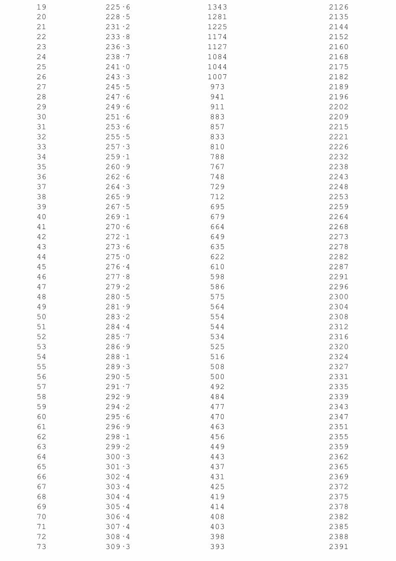
19 225·6 1343 212620 228·5 1281 213521 231·2 1225 214422 233·8 1174 215223 236·3 1127 216024 238·7 1084 216825 241·0 1044 217526 243·3 1007 218227 245·5 973 218928 247·6 941 219629 249·6 911 220230 251·6 883 220931 253·6 857 221532 255·5 833 222133 257·3 810 222634 259·1 788 223235 260·9 767 223836 262·6 748 224337 264·3 729 224838 265·9 712 225339 267·5 695 225940 269·1 679 226441 270·6 664 226842 272·1 649 227343 273·6 635 227844 275·0 622 228245 276·4 610 228746 277·8 598 229147 279·2 586 229648 280·5 575 230049 281·9 564 230450 283·2 554 230851 284·4 544 231252 285·7 534 231653 286·9 525 232054 288·1 516 232455 289·3 508 232756 290·5 500 233157 291·7 492 233558 292·9 484 233959 294·2 477 234360 295·6 470 234761 296·9 463 235162 298·1 456 235563 299·2 449 235964 300·3 443 236265 301·3 437 236566 302·4 431 236967 303·4 425 237268 304·4 419 237569 305·4 414 237870 306·4 408 238271 307·4 403 238572 308·4 398 238873 309·3 393 2391

74 310·3 388 239475 311·2 383 239776 312·2 379 240077 313·1 374 240378 314·0 370 240579 314·9 366 240880 315·8 362 241181 316·7 358 241482 317·6 354 241783 318·4 350 241984 319·3 346 242285 320·1 342 242586 321·0 339 242787 321·8 335 243088 322·6 332 243289 323·5 328 243590 324·3 325 243891 325·1 322 244092 325·9 319 244393 326·7 316 244594 327·5 313 244895 328·2 310 245096 329·0 307 245397 329·8 304 245598 330·5 301 245799 331·3 298 2460100 332·0 295 2462110 339·2 271 2486120 345·8 251 2507130 352·1 233 2527140 357·9 218 2545150 363·4 205 2561160 368·7 193 2577170 373·6 183 2593180 378·4 174 2608190 382·9 166 2622200 387·3 158 2636210 391·5 151 2650220 395·5 145 2663230 399·4 140 2675240 403·1 134 2687
[Pg511]
In the absence of any direct method of determining the general relation between the pressure andvolume of common steam, empirical formulæ expressing it have been proposed by differentmathematicians.
The late Professor Navier proposed the following:—Let S express the volume of steam intowhich an unit of volume of water is converted under the pressure P, this pressure being expressedin kilogrammes per square mètre. Then the relation between S and P will be
S =a
,b + mP

where a = 1000, b = 0·09, and m = 0·0000484.
This formula, however, does not agree with experiment at pressures less than an atmosphere. M.de Pambour, therefore, proposes the following changes in the values of its co-efficients:—Let Pexpress the pressure in pounds per square foot; and let
a = 10000 b = 0·4227 m = 0·00258,
and the formula will be accurate for all pressures. For pressures above two atmospheres thefollowing values give more accuracy to the calculation:—
a = 10000 b = 1·421 m = 0·0023.
In these investigations I shall adopt the following modified formula. The symbols S and Pretaining their signification, we shall have
S =a
, (10.)b + P
where
a = 3875969 b = 164.
These values of a and b will be sufficiently accurate for practical purposes for all pressures,and may be used in reference to low-pressure engines of every form, as well as for high-pressureengines which work expansively.
When the pressure is not less than 30 pounds per square inch, the following values of a and bwill be more accurate:—
a = 4347826 b = 618.
On the Expansive Action of Steam.
The investigation of the effect of the expansion of steam which has been given in the text, isintended to convey to those who are not conversant with the principles and language of analysis,some notion of the nature of that mechanical effect to which the advantages attending the expansiveprinciple are due. We shall now, however, explain these effects more accurately. [Pg512]
The dynamical effect produced by any mechanical agent is expressed by the product of theresistance overcome and the space through which that resistance is moved.
Let
P = the pressure of steam expressed in pounds per square foot.S = the number of cubic feet of steam of that pressure produced by the
evaporation of a cubic foot of water.E = the mechanical effect produced by the evaporation of a cubic foot of
water expressed in pounds raised one foot.
Then we shall have E = PS; and if W be a volume of water evaporated under the pressure P, themechanical effect produced by it will be WPS.
By (10.) we have
SP = a − bS.
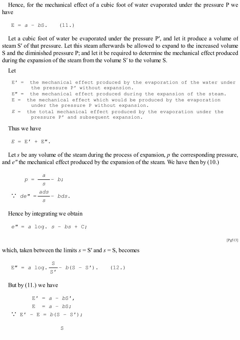
Hence, for the mechanical effect of a cubic foot of water evaporated under the pressure P wehave
E = a − bS. (11.)
Let a cubic foot of water be evaporated under the pressure P′, and let it produce a volume ofsteam S′ of that pressure. Let this steam afterwards be allowed to expand to the increased volumeS and the diminished pressure P; and let it be required to determine the mechanical effect producedduring the expansion of the steam from the volume S′ to the volume S.
Let
E′ = the mechanical effect produced by the evaporation of the water underthe pressure P′ without expansion.
E″ = the mechanical effect produced during the expansion of the steam.E = the mechanical effect which would be produced by the evaporation
under the pressure P without expansion.E = the total mechanical effect produced by the evaporation under the
pressure P′ and subsequent expansion.
Thus we have
E = E′ + E″.
Let s be any volume of the steam during the process of expansion, p the corresponding pressure,and e″ the mechanical effect produced by the expansion of the steam. We have then by (10.)
p =a
− b;s
∵ de″ =ads
− bds.s
Hence by integrating we obtain
e″ = a log. s − bs + C;
[Pg513]
which, taken between the limits s = S′ and s = S, becomes
E″ = a log.S
− b(S − S′). (12.)S′
But by (11.) we have
E′ = a − bS′,
E = a − bS;
∵ E′ − E = b(S − S′);
S

∵ E″ = a log. − E′ + E;S′
∵ E = E″ + E′ = a log.S
+ E. (13.)S′
Or,
E = a (1 + log.S ) − bS. (14.)S′
Hence it appears that the mechanical effect of a cubic foot of water evaporated under thepressure P may be increased by the quantity a log. S/S′, if it be first evaporated under the greaterpressure P′, and subsequently expanded to the lesser pressure P.
The logarithms in these formulæ are hyperbolic.
To apply these principles to the actual case of a double acting steam engine,
Let
L = the stroke of the piston in feet.A = the area of the piston in square feet.n = the number of strokes of the piston per minute.∵ 2nAL = the number of cubic feet of space through which the piston moves
per minute.
Let
cLA = the clearage, or the space between the steam valve and the piston ateach end of the stroke.
∵ The volume of steam admitted through the steam valve at each stroke ofthe engine will be 2n AL(1 + c).
Let
V = the mean speed of the piston in feet per minute,∵ 2nL = V.
The volume of steam admitted to the cylinder per minute will therefore be VA (1 + c), the part ofit employed in working the piston being VA.
Let
W = the water in cubic feet admitted per minute in the form of steamthrough the steam valve.
S = the number of cubic feet of steam produced by a cubic foot of water.
[Pg514]
Hence we shall have
WS = VA (1 + c);
VA(1 + c)

∵ S = . (15.)W
Since by (10.) we have
P = a− b;
S
∵ P = Wa
− b. (16.)VA(1 + c)
By which the pressure of steam in the cylinder will be known, when the effective evaporation,the diameter of the cylinder, and speed of the piston, are given.
If it be required to express the mechanical effect produced per minute by the action of steam onthe piston, it is only necessary to multiply the pressure on the surface of the piston by the space perminute through which the piston moves. This will give
VAP = Wa
− VAb; (17.)1 + c
which expresses the whole mechanical effect per minute in pounds raised one foot.
If the steam be worked expansively, let it be cut off after the piston has moved through a part ofthe stroke expressed by e.
The volume of steam of the undiminished pressure P′ admitted per minute through the valvewould then be
VA (e + c);
and the ratio of this volume to that of the water producing it being expressed by S′, we should have
S′ = VA(e + c)
.W
The final volume into which this steam is subsequently expanded being VA(1 + c), its ratio tothat of the water will be
S = VA (1 + c)
.W
The pressure P′, till the steam is cut off, will be
P′ = Wa
− b. (18.)VA(e + c)
The mechanical effect E′ produced per minute by the steam of full pressure will be
Wae
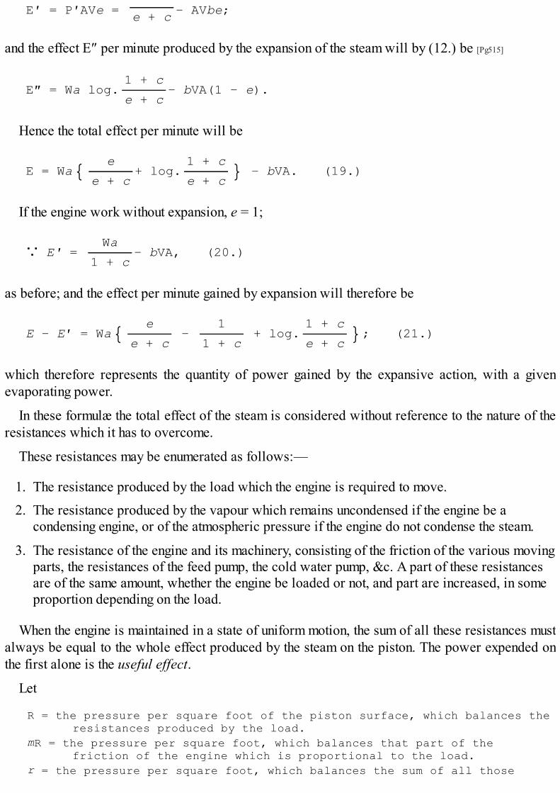
E′ = P′AVe = − AVbe;e + c
and the effect E″ per minute produced by the expansion of the steam will by (12.) be [Pg515]
E″ = Wa log.1 + c
− bVA(1 − e).e + c
Hence the total effect per minute will be
E = Wa{ e+ log.
1 + c } − bVA. (19.)e + c e + c
If the engine work without expansion, e = 1;
∵ E′ = Wa
− bVA, (20.)1 + c
as before; and the effect per minute gained by expansion will therefore be
E − E′ = Wa{ e −
1 + log.
1 + c }; (21.)e + c 1 + c e + c
which therefore represents the quantity of power gained by the expansive action, with a givenevaporating power.
In these formulæ the total effect of the steam is considered without reference to the nature of theresistances which it has to overcome.
These resistances may be enumerated as follows:—
1. The resistance produced by the load which the engine is required to move.2. The resistance produced by the vapour which remains uncondensed if the engine be a
condensing engine, or of the atmospheric pressure if the engine do not condense the steam.
3. The resistance of the engine and its machinery, consisting of the friction of the various movingparts, the resistances of the feed pump, the cold water pump, &c. A part of these resistancesare of the same amount, whether the engine be loaded or not, and part are increased, in someproportion depending on the load.
When the engine is maintained in a state of uniform motion, the sum of all these resistances mustalways be equal to the whole effect produced by the steam on the piston. The power expended onthe first alone is the useful effect.
Let
R = the pressure per square foot of the piston surface, which balances theresistances produced by the load.
mR = the pressure per square foot, which balances that part of thefriction of the engine which is proportional to the load.
r = the pressure per square foot, which balances the sum of all those

resistances that are not proportional to the load.
The total resistance, therefore, being R + mR + r, which, when the mean motion of the piston isuniform, must be equal to the mean pressure on the piston. The total mechanical effect [Pg516] musttherefore be equal to the total resistance multiplied by the space through which that resistance isdriven. Hence we shall have
{R(1 + m) + r}VA = Wa{ e+ log.
1 + c } − VAb;e + c e + c
∵ RVA(1 + m) = Wa{ e+ log.
1 + c } − VA(b + r).e + c e + c
For brevity, let
e′ = a{ e + log.
1 + c };e + c e + c
∵ RVA(1 + m) = We′ − VA(b + r). (22.)
By solving this for VA, we obtain
VA = We′
;R(1 + m) + b + r
∵ RVA = We′R
. (23.)R(1 + m) + b + r
This quantity RVA, being the product of the resistance RA, of the load reduced to the surface ofthe piston, multiplied by the space through which the piston is moved, will be equal to the loaditself multiplied by the space through which it is moved. This being, in fact, the useful effect of theengine, let it be expressed by U, and we shall have
U = We′R
. (24.)R(1 + m) + b + r
Or by (22.),
U(1 + m) = We′ − VA(b + r). (25.)
The value of the useful effect obtained from these formulæ will be expressed in pounds, raisedone foot per minute, W being the effective evaporation in cubic feet per minute, A the area of thepiston in square feet, and V the space per minute through which it is moved, in feet.
Since a resistance amounting to 33,000 pounds moved through one foot per minute is called one-horse power, it is evident that the horse power H of the engine is nothing more than the usefuleffect per minute referred to a larger unit of weight or resistance; that is to 33,000 pounds insteadof one pound. Hence we shall have

H = U . (26.)33000
Since the useful effect expressed in (24.) and (25.) is that due to a number of cubic feet of water,expressed by W, we shall obtain the effect due to one cubic foot of water, by dividing U by W. If,therefore, U′ be the effect produced by the effective evaporation of a cubic foot of water, we shallhave [Pg517]
U′ = U. (27.)
W
If the quantity of fuel consumed per minute be expressed by F, the effect produced by the unit offuel, called the DUTY of the engine, will, for like reason, be
D = U. (28.)
F
If the fuel be expressed in hundredweights of coal, then D will express the number of pounds'weight raised one foot by a hundredweight of coal.
By solving (24.) and (25.) for W, we obtain
W = U{R(1 + m) + b + r}
, (29.)Re′
W = 1
{U(1 + m) + VA(b + r)}. (30.)e′
By eliminating U, by (26.), we shall have
W = 33000 H{R(1 + m) + b + r}
, (31.)Re′
W = 1
{33000 H(1 + m) + VA(b + r)}. (32.)e′
The evaporation necessary per horse power per minute will be found by putting H = 1 in theseformulæ.[41]
It will be observed that the quantities A and V, the area of the cylinder and the speed of thepiston, enter all these formulæ as factors of the same product. Other things, therefore, being thesame, the speed of the piston will be always inversely as the area of the cylinder. In fact, VA is thevolume of steam per minute employed in working the piston, and if the piston be increased ordiminished in magnitude, its speed must be inversely [Pg518] varied by the necessity of being stillmoved through the same number of cubic feet by the same volume of steam.
It has been already stated in the text, that no satisfactory experiments have yet been made, bywhich the numerical value of the quantity r can be exactly known. In engines of different
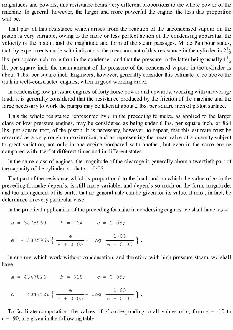
magnitudes and powers, this resistance bears very different proportions to the whole power of themachine. In general, however, the larger and more powerful the engine, the less that proportionwill be.
That part of this resistance which arises from the reaction of the uncondensed vapour on thepiston is very variable, owing to the more or less perfect action of the condensing apparatus, thevelocity of the piston, and the magnitude and form of the steam passages. M. de Pambour states,that, by experiments made with indicators, the mean amount of this resistance in the cylinder is 21⁄2lbs. per square inch more than in the condenser, and that the pressure in the latter being usually 11⁄2lb. per square inch, the mean amount of the pressure of the condensed vapour in the cylinder isabout 4 lbs. per square inch. Engineers, however, generally consider this estimate to be above thetruth in well-constructed engines, when in good working order.
In condensing low pressure engines of forty horse power and upwards, working with an averageload, it is generally considered that the resistance produced by the friction of the machine and theforce necessary to work the pumps may be taken at about 2 lbs. per square inch of piston surface.
Thus the whole resistance represented by r in the preceding formulæ, as applied to the largerclass of low pressure engines, may be considered as being under 6 lbs. per square inch, or 864lbs. per square foot, of the piston. It is necessary, however, to repeat, that this estimate must beregarded as a very rough approximation; and as representing the mean value of a quantity subjectto great variation, not only in one engine compared with another, but even in the same enginecompared with itself at different times and in different states.
In the same class of engines, the magnitude of the clearage is generally about a twentieth part ofthe capacity of the cylinder, so that c = 0·05.
That part of the resistance which is proportional to the load, and on which the value of m in thepreceding formulæ depends, is still more variable, and depends so much on the form, magnitude,and the arrangement of its parts, that no general rule can be given for its value. It must, in fact, bedetermined in every particular case.
In the practical application of the preceding formulæ in condensing engines we shall have [Pg519]
a = 3875969 b = 164 c = 0·05;
e′ = 3875969{ e+ log.
1·05 }.e + 0·05 e + 0·05
In engines which work without condensation, and therefore with high pressure steam, we shallhave
a = 4347826 b = 618 c = 0·05;
e′ = 4347826{ e+ log.
1·05 }.e + 0·05 e + 0·05
To facilitate computation, the values of e′ corresponding to all values of e, from e = ·10 toe = ·90, are given in the following table:—

e CondensingEngines e′.
Non-condensingEngines e′.
e CondensingEngines e′.
Non-condensingEngines e′.
·10 10126265 11359029 ·51 5966367 6692708·11 9956867 11169008 ·52 5903837 6622565·12 9793136 10985344 ·53 5842288 6553525·13 9634926 10807875 ·54 5781693 6485552·14 9482029 10636364 ·55 5722024 6418619·15 9334219 10470560 ·56 5663251 6352693·16 9191251 10310186 ·57 5605353 6287745·17 9052888 10154978 ·58 5548297 6223742·18 8918896 10004675 ·59 5492064 6160662·19 8789043 9859014 ·60 5436628 6098478·20 8663120 9717760 ·61 5381969 6037166·21 8540918 9580682 ·62 5328065 5976699·22 8422242 9447559 ·63 5274896 5917057·23 8306916 9318193 ·64 5222444 5858219·24 8194770 9192396 ·65 5170684 5800159·25 8085644 9069984 ·66 5119605 5742860·26 7979392 8950796 ·67 5069186 5686304·27 7875870 8834674 ·68 5019410 5630469·28 7774952 8721468 ·69 4970263 5575340·29 7676514 8611048 ·70 4921727 5520894·30 7580447 8503284 ·71 4873790 5467121·31 7486640 8398056 ·72 4826434 5414000·32 7394990 8295250 ·73 4779648 5361519·33 7305407 8194760 ·74 4733417 5309659·34 7217807 8096496 ·75 4687728 5258408·35 7132097 8000352 ·76 4642569 5207751·36 7048206 7906249 ·77 4597928 5157676·37 6966058 7814100 ·78 4553794 5108170·38 6885585 7723832 ·79 4510155 5059218·39 6806720 7635365 ·80 4466999 5010808·40 6729408 7548642 ·81 4424317 4962931·41 6653578 7463580 ·82 4382096 4915569·42 6579187 7380132 ·83 4340332 4868720·43 6506174 7298230 ·84 4299010 4822368·44 6434491 7217822 ·85 4258120 4776500·45 6364099 7138858 ·86 4217658 4731113·46 6294944 7061285 ·87 4177613 4686192·47 6226989 6985058 ·88 4137974 4641728·48 6160190 6910126 ·89 4098737 4597713·49 6094510 6836450 ·90 4059893 4554140·50 6029916 6763992
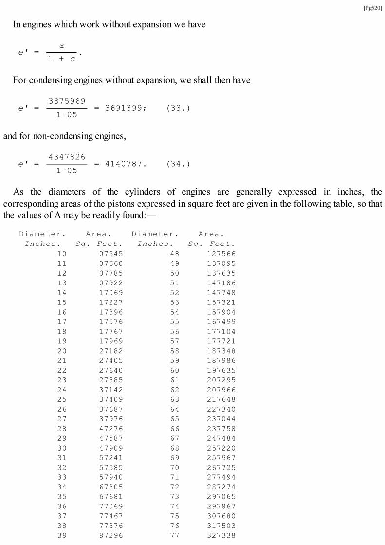
[Pg520]
In engines which work without expansion we have
e′ = a
.1 + c
For condensing engines without expansion, we shall then have
e′ = 3875969
= 3691399; (33.)1·05
and for non-condensing engines,
e′ = 4347826
= 4140787. (34.)1·05
As the diameters of the cylinders of engines are generally expressed in inches, thecorresponding areas of the pistons expressed in square feet are given in the following table, so thatthe values of A may be readily found:—
Diameter. Area. Diameter. Area.Inches. Sq. Feet. Inches. Sq. Feet.
10 07545 48 12756611 07660 49 13709512 07785 50 13763513 07922 51 14718614 17069 52 14774815 17227 53 15732116 17396 54 15790417 17576 55 16749918 17767 56 17710419 17969 57 17772120 27182 58 18734821 27405 59 18798622 27640 60 19763523 27885 61 20729524 37142 62 20796625 37409 63 21764826 37687 64 22734027 37976 65 23704428 47276 66 23775829 47587 67 24748430 47909 68 25722031 57241 69 25796732 57585 70 26772533 57940 71 27749434 67305 72 28727435 67681 73 29706536 77069 74 29786737 77467 75 30768038 77876 76 31750339 87296 77 327338

40 87727 78 33718341 97168 79 34703942 97621 80 34790743 107085 81 35778544 107559 82 36767445 117045 83 37757446 117541 84 38748547 127048 85 397406
Diameter. Area. Diameter. Area.Inches. Sq. Feet. Inches. Sq. Feet.
86 407339 124 83786387 417283 125 85722188 427237 126 86759089 437202 127 87797090 447179 128 89736191 457166 129 90776392 467164 130 92717593 477173 131 93759994 487193 132 95703395 497224 133 96747996 507265 134 97793597 517318 135 99740298 527382 136 100788099 537456 137 1027369
100 547542 138 1037869101 557638 139 1057380102 567745 140 1067901103 577863 141 1087434104 587992 142 1097977105 607132 143 1117532106 617283 144 1137097107 627445 145 1147674108 637617 146 1167261109 647801 147 1177859110 657995 148 1197468111 677201 149 1217088112 687417 150 1227719113 697644 151 1247361114 707882 152 1267013115 727131 153 1277676116 737391 154 1297351117 747662 155 1317036118 757944 156 1327732119 777236 157 1347439120 787540 158 1367157121 797854 159 1377886122 817180 160 1397626123 827516 161 1417377
[Pg521]
The practical application of the preceding formulæ will be shown by the following examples.
EXAMPLES.

1. A 36-inch cylinder with 51⁄2 feet stroke is supplied by a boiler evaporating effectively 60cubic feet of water per hour, and the piston makes 20 strokes per minute without expansion;—what is the power of the engine and the pressure of steam in the cylinder?
Let it be assumed that r = 6 × 144 = 864 and m = 0·1. Since the engine is a condensing engine,we have b = 164 and e′ = 3691399. By the formulæ (25.) and (26.) we have
H = We′ − VA(b + r)
;33000(1 + m)
and since by the data we have
W = 1 A = 7·069 V = 2nL = 40 × 5·5 = 220,
the formula, by these substitutions, becomes
H = 3691399 − 220 × 1028 × 7·069
;33000 × 1·1
∵ H = 57·6.
Since e = 1, the pressure P of steam in the cylinder, by (18.), is
P = We′
− b.VA
Therefore
P = 3691399
− 164 = 2210;1555·18
which being the pressure in pounds per square foot, the pressure per square inch will be 151⁄3 lbs.
2. To find the effective evaporation necessary to produce a power of 80 horses with the sameengine. Also, find the pressure of steam in the cylinder, the speed of the piston being the same.
By the formula (32.), with the above substitutions, we have
W = 33000 × 80 × 1·1 + 220 × 7069 × 1028
= 1·22.3691399
The evaporating power would therefore be only increased 22 per cent., while the workingpower of the engine would be increased nearly 40 per cent.
The pressure P in the cylinder will be given, by (18.), as before.
P = 1·22 × 3691399
− 164 = 2732;1555·18
which is equivalent to 19 lbs. per square inch. [Pg522]

3. What must be the diameter of a cylinder to work with a power of a hundred horses,supplied by a boiler evaporating effectively 70 cubic feet of water per hour, the mean speed ofthe piston being 240 feet per minute, and the steam being cut off at half stroke? Also, what willbe the full pressure of steam on the piston?
Taking, as in the former examples, m = 0·1, b = 164, and r = 864, we shall have
H = 100 W = 7⁄6 V = 240,
and by the column for condensing engines, in table, p. 519, we have e′ = 6029916, where e = 0·50.Making these substitutions in
We′ = 33000 H(1 + m) + VA(b + r),
we shall have
(7⁄6) × 6029916 = 3300000 × 1·1 + 240 × 1028 × A.
Whence we find
A = 13·8;
and by the table, p. 520, the corresponding diameter of the cylinder will be 501⁄3 inches.
If P′ be the full pressure of the steam, we shall have, by (18.),
P′ = Wa
− b.VA(e + c)
Making in this the proper substitutions, we have
P′ = 7⁄6 × 3875969 − 164 = 2318;
240 × 13·8 × 0·55
which being in pounds per square foot, the pressure per square inch will be 161⁄10 lbs.

FOOTNOTES:[40] M. de Pambour states that the increased volume is 1364 cubic inches.
[41] Formulæ equivalent to some of the preceding are given, with numerous others, by M. de Pambour, in his Theory ofthe Steam Engine. These mathematical details contain nothing new in principle, being merely the application of theknown principles of general mechanics to this particular machine. M. de Pambour objects against the methods ofcalculating the practical effects of steam engines generally adopted by engineers in this country. Their estimates ofthe loss of power by friction, imperfect condensation, and other causes, are, as I have stated in this volume, vague,and can be regarded at best as very rough approximations; but, subject to the restrictions under which their methodsof calculation are always applied, they are by no means so defective as M. de Pambour supposes. He proves whathe considers to be their inaccuracy, by applying them in cases in which they are never intended to be applied byEnglish engineers. Those who desire to reduce to general algebraical formulæ the effects of the different kinds ofsteam engines will, however, find the volume of M. de Pambour of considerable use.

INDEX.
[Pg523]
TOC

Air, elasticity of, 28;May be partially expelled from a vessel by the application of heat, 44.
America, steam navigation first established in, 487;Circumstances which led to it, 488;
Fitch and Rumsey, their attempts to apply the single-acting engine to the propulsion ofvessels, 489;
Stevens of Hoboken commences experiments on steam navigation, 489;Experiments of Livingstone and Fulton, 489;Fulton's first boat, 490;The Hudson navigated by steam, 491;
Extension and improvement of river navigation, 492;American steamers, 494;Difference between them and European steamers, 494;Steamers on the Hudson, 494;American paddle-wheels, 495;Sea-going American steamers, 496;
Speed attained by American steamers, 497;Lake steamers, 499;The Mississippi and its tributaries, 499;Steam-boats navigating it, 500;Their structure and machinery, 500;
New Orleans Harbour, 503;Steam tugs, 503.
Atmosphere, 38;Weight of, 39.
Atmospheric air, mechanical properties of, 38;Composition of, 253.
Atmospheric engine, Thomas Newcomen the reputed inventor of, 62;Description of, as first constructed by Newcomen, 67;
The operation of considered, 69;Not unfrequently used in preference to the modern steam engine, 72;Advantages which it possessed over Savery's, 73;

Considerably improved by Beighton, 75;John Smeaton investigates this machine, 76;Brindley obtains a patent for improvements in, 76;
Applied by Champion of Bristol to raise water, 181;Possessed but limited power of adaptation to a varying load, 151;Expedient to remedy this, 151;Working-beam, cylinder, and piston applied to by Newcomen, 322.
Atmospheric pressure rendered available as a mechanic agent by Denis Papin, 38;Means of measuring the force of, 39;
The idea of using against a vacuum or partial vacuum to work a piston in a cylinder,suggested by Otto Guericke, 73.
Barometer gauge, 272.
Barton's piston, 248.
Beighton, his improvement of the atmospheric engine, 75.
Black, Dr., his doctrine of latent heat, 93.
Blasco de Garay, his contrivance to propel vessels, 16;The contrivance of, probably identical with that of Hero, 17.
Blinkensop, his locomotive engine, 337.
Blowing-box, 429.
Blowing out, Seaward's method of, 454.
Blow-off cocks, 452.
Boiler, forms of, most convenient, 255;The waggon boiler adopted by Watt, 255;Furnace, 256;Method of feeding, 257;Combustion of gas in flues, 260;
Mr. Williams's method of consuming the unburned gases which escape from the grate,and are carried through the flues, 260;
Construction of grate and ash-pit, 261;Magnitude of heating surface of boiler, 262;

Capacity of, must be proportioned to the quantity of water to be evaporated, 263;Water-space and steam-space in boiler, 263;Proportion of water-space in the boiler, how to be regulated, 264;
Position of flues, 264;Method of feeding, 265;The magnitude of the feed should be equal to the quantity of water evaporated, 265;Different methods for indicating the level of the water in the boiler, 266;Level guages, 266;
Self-regulating feeder, 267;Another method of arranging, 269;Steam gauge, 270;Thermometer gauge, 271;Barometer gauge, 272;The indicator to measure the mean efficient force of the piston invented by Watt, 274;
The counter contrived by Watt, 278;Safety valve, 279;Fusible plugs used in high pressure boilers, 280;Self-regulating damper, 281;Self-regulating furnace invented by Brunton, 283;
Duty of a boiler, 294;Boilers of locomotive engines, 351;Construction of the boiler of Gurney's steam carriage, 423;All boilers require occasional cleansing, 427;Gurney's method of removing crust of deposited matter in boilers, 427;
The boiler of Dr. Church's engine formed of copper, 439;Boilers in marine engines, 449;Effects of sea-water in, 450;Remedies for them, 451;Substitution of copper for iron, 460;Expedient of coating boilers with felt, applied by Watt, 463.
Booth, Mr., his report on locomotive engines, 361.
Boulton and Watt's experiments on the horse power of engines, 288.

Branca, Giovanni, his machine for propelling a wheel by a blast of steam, 22.
Brindley (James) obtains a patent for improvements in atmospheric engine, 76;Undertook to erect an engine at Newcastle-under-Lyne, 76;Discouraged by the obstacles thrown in his way, 76.
Brougham, Lord, his sketch of Watt's character, 313;
Inscription from the pen of, on Watt's monument in Westminster Abbey, 320.
Buffers, 404.
Cartwright's engine to use the vapour of alcohol to work the piston, 245;His piston, 247.
Cawley and Newcomen obtain a patent for the atmospheric engine, 64.
Champion applies atmospheric engine to raise water, 181.
Chapman, Messrs., their locomotive engine, 337.
Chlorine introduced in bleaching by Watt, 310.
Church, Dr., his steam engine, 439;The boiler formed of copper, 439.
Coals, the virtues and powers which steam has conferred upon, 6;The amount of labour a bushel of performs by means of the steam engine, compared with
horse power, 7;Constituents of, 252;
Process of combustion, 252.
Coal mines, apprehensions as to the possibility of the exhaustion of groundless, 8.
Cocks, friction on, 240.
Cocks and valves, 227.
Combustion of gas in flues, 260.
Condensation by injection, accidental discovery of, 69.
Condensation in the cylinder incompatible with a due economy of fuel, 120.
Condensing principle, circumstance which led to Savery's discovery of, 47.
Condensing pipe in Savery's engine, 52.

Condensing out of the cylinder, 120.
Condensing jet, 191.
Conical steam valves, 228.
Conversion of ice into water, 103;Of water into steam, 105.
Copying press invented by Watt, 302.
Cornish system of inspection, 297.
Cornish engines, improvement of, 298;Historical detail of the duty of, 299.
Cylinders, Wilkinson's machine for accurately boring the insides of, 149.
D valve, 230.
Dalton and Gay-Lussac, law of, relating to the pressure of elastic bodies, 171.
Dixon, Mr. The substitution of brass for copper tubes in locomotive engines ascribed to him,370.
Double clack-valve, 228.
Eccentric, 225;
Two expedients to reverse the position of, 379.
Effect of an engine, 285.
Elastic fluids. The law according to which the pressure of, increases with their temperature,discovered by Dalton and Gay-Lussac, 171.
Evaporation of water and other liquids, physical and mechanical principles connected with,97.
Expansion of common steam, effects of, 173.
Expansive action of steam, 159;Stated by Watt in a letter to Dr. Small, 157;Its principle explained, 158;Mechanical effect resulting from it, 161;Computed effect of cutting off steam at different portions of the stroke, 162;
Involves the condition of a variation in the intensity of the moving power, 163;

Expedients for equalising the power, 164;The expansive principle in the engines constructed by Boulton and Watt, limited, 165;Its more extensive application in the Cornish engines, 165;
Methods of equalising, 174;Description of Hornblower's engine for this purpose, 174.
Expansive principle, application of in marine engines, 466.
Farey on the steam engine, quotation from, relative to Savery's engine, 58;His evidence before the House of Commons, 435.
Field, construction of his split paddle, 478.
Fitch and Rumsey, their attempts to apply the single-acting engine to the propulsion ofvessels, 489.
Flues, position of, 264.
Fluids, of two kinds, 25;Mechanical properties of, 25;Elastic, 27;
Experimental proof that they press equally in all directions, 41.
Fly-wheel, 205.
Four-way cock, 239;Disadvantages of, 240.
Fuel, means of economising, in marine furnaces, 463.
Fulton and Livingstone, their experiments in steam navigation, 489.
Fulton's first boat, 490.
Furnace, self-regulating, invented by Brunton, 283.
Fusible plugs used in high-pressure boilers, 280.
Galloway, his paddle-wheel described, 476.
Gas, elasticity of, 28.
Gay-Lussac and Dalton, law of, relating to the pressure of elastic bodies, 171.
Governor, adaptation of, 209.

Gradients, restrictions on, 411;Disposition of, should be uniform, 415.
Great Western Railway, Dr. Lardner's experiments on, 408.
Griff, proposals to drain a colliery at, mentioned by Desaguliers, 64.
Gurney's steam carriage, 423;Construction of the boiler of, 423;
His method of removing crust of deposited matter in boilers, 427;His experiments on common roads, 432.
Hall, his condensers described, 458.
Hancock, his steam carriage, 436;In what manner it differs from that of Gurney, 437.
Harris, Dr., mentions Savery's engine in his "Lexicon Technicum," 56.
Heat, effects of upon water, 29;Waste of in atmospheric engine, 89;An examination of the analogous effects produced by the continued application of, to
water in the liquid state, 102;
Radiation of, 254.
Heating by steam brought forward by Watt, 303."Hecla," experiments with the, 412.
Hero of Alexandria, description of his machine, 12.
High pressure engines described, 321;One of the earliest forms of the steam engine, 322;Obscurely described in the "Century of Inventions," 322;Construction of the first, by Messrs. Trevethick and Vivian, 324.
Hooke exposes the fallacy of Papin's project, 64.
Horse carriages compared with steam, 435.
Horse power of steam engines, 288;Smeaton's estimation of, 288;
Boulton and Watt's experiments on, 288.

Howard's description of his marine engine, 464.
Hudson, the, navigated by steam, 491.
Hull, Jonathan, his application of the steam engine to water wheels, 180.
Humphrey. His marine engine described, 470.
Huskisson, Mr., death of, 329.
Hydrogen, 253.
India, steam navigation to, 483.
Indicator invented by Watt, 274.
Jeffrey, Lord; his sketch of the character of Watt, 315.
Kinneal, description of Watt's experimental engine at, 131.
Lake steamers, 499.
Lardner's, Dr., experiments on the Manchester Railway in 1832, 357;His experiments in 1838, 406;Experiments on the Great Western Railway, 408.
Leupold's engine, description of, 323.
Level gauges, 266.
Linen, machine for drying by steam, invented by Watt, 303.
Liverpool and Manchester railroad, effects of the introduction of steam transport on, 329;
Want of experience in the construction of the engines, 329;Death of Mr. Huskisson, 329;Proceedings of the directors, 342;Premium offered by them for the best engine, 344;Experimental trial, 344.
Livingstone and Fulton, experiments of in steam navigation, 489.
Locomotive engine, history of, 328;
Blinkensop's engine, 337;Chapman's engine, 337;

Walking engine, 337;Mr. Stephenson's engine at Killingworth, 339;Defect of, 341;
Description of the "Rocket," 345;The "Sanspareil," 347;The "Novelty," 349;Superiority of the "Rocket," 350;Subsequent improvements in the locomotive engine, 352;
Table, showing the economy of fuel gained by subdividing the flue into tubes, 354;Engines constructed in the form of the "Rocket" subject to two principal defects, 354;These defects remedied, 355;Improved by the adoption of a more contracted blast pipe, 356;Dr. Lardner's experiments in 1832, 357;Adoption of brass tubes, 361;
Mr. Booth's report, 361;Detailed description of the most improved locomotive engines, 364;Substitution of brass for copper tubes ascribed to Mr. Dixon, 370;Mr. Stephenson constructed the driving wheels without flanges, 383;Pressure of steam in the boiler limited by two safety-valves, 402;
Buffers, 404;Steam whistle, 404;Water tank, 404;Power of locomotive engines, 405;Evaporation of boilers, 406;
Dr. Lardner's experiments in 1838, 406;Resistance to railway trains, 407;Dr. Lardner's experiments on the Great Western Railway, 408;Restriction on gradients, 411;Experiment with the "Hecla," 412;Disposition of gradients should be uniform, 415;
Method of surmounting steep inclinations, 415;Steam carriages on common roads, 419;Difference between steam engines on railways and those used to propel carriages on
turnpike roads, 422;

Gurney's steam carriage, 423;Construction of the boiler of, 423;Escape of steam from the engines on the Liverpool road, 428;
Blowing-box, 429;Separator, 430;Difficulties in the practical working of steam carriages upon common roads, 432;Gurney's experiments on common roads, 432;Prejudice against locomotive engines on common roads, 432;
Not more destructive to roads than carriages drawn by horses, 433;Report of the committee of the House of Commons, 433;Weight of steam carriages, 433;Two methods of applying locomotives upon common roads, 434;Horse carriages compared with, 435;Farey's evidence before the House of Commons, 435;
Risk of accident from explosion extremely slight, 435;Hancock's steam carriage, 436;In what manner it differs from that of Gurney, 437;Ogle's steam carriage, 438;His evidence before the House of Commons, 439;
Dr. Church's steam engine, 439;The boiler of formed of copper, 439.
Lunar Society, Boulton and Watt leading members in, 302.
Marine engines, form and arrangement of, 441;Difference between marine and land engines, 443;Engine-room, arrangement of, 446;Boilers in, 449;
Effects of sea-water on boilers, 450;Remedies for them, 451;Blow-off cocks, 452;Indicators of saltness, 452;Seaward's indicator, 454;His method of blowing out, 454;

Method of Maudslay and Field to preserve freshness of water in the boiler, 456;Brine pumps, 457;Tubular condensers applied by Mr. Watt, 457;
Hall's condensers, 458;Substitution of copper for iron boilers, 461;Process of stoking, 462;Marine furnaces, 463;Expedient of coating boilers with felt applied by Watt, 463;
Means of economising fuel, 463;Description of Howard's engine, 464;Application of the expansive principle in marine engines, 466;Recent improvements of Messrs. Maudslay and Field, 467;Humphrey's engine, 470;Common paddle-wheel, 472;
Defect of, 474;Feathering paddles, 474;Galloway's paddle-wheel, 476;Field's split paddle, 478;Proportion of power to tonnage, 480;
Iron steam vessels, 482.
Mariotte's law relating to pressure, 171.
Maudslay and Field, their method to preserve the requisite freshness of water in the boiler,456;Brine pumps, 457;Recent improvements of in marine engines, 466.
Metallic pistons, 244;Cartwright's engine, 245;An improved form given to by Barton, 248.
Mill work, Stewart's application of the steam engine to, 182.
Mines, the drainage of, Watt endeavours to bring to perfection the application of the steamengine to, 178.
Mississippi and its tributaries, 499;

Steam-boats on, 500;Their structure and machinery, 500.
Morland, Sir Samuel, his application of steam to raise water, 34;The reputed inventor of several ingenious contrivances, 34;
His work in French upon the raising of water, 35;Extract from it, 35;Evelyn's account of his visit to, 36.
Murray's slide-valve, 229.
Newcomen, Thomas, the reputed inventor of the atmospheric engine, 62;His acquaintance with Dr. Hooke, 62;Acquainted with Papin's writings, 64;
The merits of his engine ascribed principally to its mechanism and combinations, 73;Obtains with Cawley a patent for the atmospheric engine, 64;Resumes the old method of raising water from mines by ordinary pumps, 65;The means proposed to effect this, 66;First conception of the atmospheric engine, 66;Description of his construction of atmospheric engine, 67;
Suggestion of a better method of condensation than the application of cold water on theexternal surfaces of the cylinder, 69;
He abandons the external cylinder, 69;Applied the working-beam, cylinder, and piston to the atmospheric engine, 322.
New Orleans Harbour, 503.
"Novelty," description of the, a locomotive engine, 349.
Ogle, his steam carriage, 438;His evidence before the House of Commons, 439.
Otto Guericke, his suggestion relative to atmospheric pressure, 73.
Oxley made the first attempt to drive water-wheels by the steam engine, 182.
Paddle-wheel described, 472;Defect of, 474;
Feathering paddles, 474;

Galloway's paddle-wheel, 476;Field's split paddle, 478.
Paddle-wheels of American steamers, 495.
Papin, Denis, conceived the idea of rendering atmospheric pressure available as amechanical agent, 37;Description of his contrivance, 37;
His discovery of condensation of steam, 45;Quotation from his work relative to this discovery, 45;Explanation of this important discovery, 46;Discovers the method of producing a vacuum by the condensation of steam, 178;His projected applications of the steam engine, 178;
His proposition for the construction of an engine working by atmospheric pressure, 62;Abandons the project when informed of the principle and structure of Savery's engine,
62;His engine described, 62;This project nothing more than a reproduction of the Marquis of Worcester's engine, 63;The fallacy of his project exposed by Hooke, 64;His project for producing a vacuum under a piston by condensing the steam, published in
the "Actæ Eruditorum," 64.
Parallel motion, 195.
Physical science, the rapid progress of, 8.
Pistons, 242;
The common hemp-packed, 242;Woolf's method of tightening the packing of, without removing the lid of the cylinder,
244;This method further simplified, 244;Metallic, 244;Cartwright's engine, 245;
Cartwright's piston, 247;Invention of the indicator by Watt to measure the mean efficient force of, 274.
Piston rod and beam, methods of connecting in the double-acting engine, 193.
Pneumatic institution at Clifton, Watt one of the founders of, 310.

Potter, Humphrey, his contrivance for working the valves, 71;Improved by the substitution of a plug-frame, 72.
Power, proportion of, to tonnage in marine engines, 480.
Power and duty of steam engines, 287.
Priestley, Watt's letter to, relative to the composition of water, 307.
Pump, an illustration of force attained by a vacuum, 43.
Puppet clacks, or button valves, 144.
Rack and Sector, 194.
Railways, speed of coaches on, compared with that of stage-coaches on a common road, 7.
Railway transport, effects of, 328. 330.
Railways and stone roads compared, 420.
River navigation, extension and improvement of, 492.
"Rocket," description of the, a locomotive engine, 345;Engines constructed in the form of, subject to two principal defects, 354;
These defects remedied, 355;Improved by the adoption of a more contracted blast-pipe, 356.
Roebuck, Dr., Watt's partnership with, 130.
Rotatory motion, method of producing by sun and planet wheels, 187.
Safety-valve not adopted by Savery, 57;Invented by Papin, 57;Description of, 57;First applied to Savery's engine by Desaguliers, 58.
"Sanspareil," description of the, a locomotive engine, 347.
Savery, Thomas, obtains a patent for an engine to raise water, 47;
Circumstance which led to his discovery of the condensing principle, 47;An account of his engine, 49;Description of the working apparatus in which the steam is used as a moving power, 51;His engine described in a work entitled "The Miner's Friend," 56;

Mentioned by Dr. Harrison in his "Lexicon Technicum," 56;Quotation from his address to the Royal Society, 56;Quotation from his address to the Miners of England, 57;
Mentioned by Bradley in his "Improvements of Planting and Gardening," 57;The safety-valve not adopted by him, 57;The safety-valve first applied to his engine by Desaguliers, 58;Farey on the steam engine quoted, 58;Further Improvements made by Desaguliers, 58;

Defects of his engine, 59;His engine applied to the drainage of mines, 59;
Further defects of, 60;The first to suggest the method of expressing the power of an engine with reference to
that of horses, 61;Failure of his engine in the work of drainage, 61;The tendency of high pressure to weaken and gradually destroy the vessels, 72;The power of his engines restricted, 73;
The atmospheric engine superior to, 73;The boiler, guage-pipes, and regulator borrowed from his engine, 73;Proposes to apply his engine as a prime mover for all sorts of machinery, 180.
Scott, Sir Walter, his sketch of the character of Watt, 314.
Sculpture, Watt's invention of machine for copying, 318.
Sea-going American steamers, 496.
Sea-water, effects of upon boilers, 450.
Seaward's slides, 235;Indicator of saltness, 454;His method of blowing out, 454.
Self-regulating damper, 281;Furnace, 283.
Separator, 430.
Single-acting engine, description of Watt's, 133. 144.
Single clack-valve, 227.
Single cock, 238.
Slide-valves, 229;
That contrived by Mr. Murray, 229.
Smeaton, John, investigates the atmospheric engine, 76;Applies himself to the improvement of wind and water mills, 181;His estimate of the horse power of engines, 288.

Solomon De Caus, description of the apparatus of, 17;M. Arago claims for him a share of the honour of the invention of the steam engine, 21;Republished, with additions, the work of Isaac De Caus, 22.
Somerset, Edward, Marquis of Worcester. Invention of the steam engine ascribed to him, 23;
Description of his contrivance, 23;His "Century of Inventions," 24;Brief account of his engine described in this work, 31;His contrivance compared with that of De Caus, 33;Many of his inventions have been reproduced and brought into general use, 34.
Steam cannot be applied immediately to any useful purpose, but requires the interposition ofmechanism, 11;
Elastic force of, recognised by the ancients only in vague and general terms, 14;The power of, formerly made to minister to the objects of superstition, mentioned by
Arago, 15;Anecdote showing the knowledge which the ancients had of the mechanical force of, 15;The discovery of the condensation of, by Papin, 45;Mechanical power obtained from the direct pressure of the elastic force of, suggested by
De Caus and Lord Worcester, 73;Latent heat of, 107;
The mechanical force of considered, 115;Watt's early experiments on, 87;Discovery of the expansive action of, 157;Expansive action of stated by Watt in a letter to Dr. Small, 157;Its principle explained, 158;
Mechanical effect resulting from it, 161;Properties of, 168;Common and super-heated steam, 168;Pressure and temperature of, 171;Relation between the temperatures of common steam and its pressure and density, 172;
Effects of the expansion of common steam, 173;Mechanical effects of, 173;Methods of equalising the varying force of expanding steam, 174;Method of producing a vacuum by the condensation of, discovered by Papin, 178;Applied to move machinery, 179;

Steam guage, 270;Heating by steam brought forward by Watt, 303;A machine for drying linen by, invented by Watt, 303;
Mode of escape of, from the engines on the Liverpool road, 429.
Steam case or jacket, invented by Watt, 124.
Steam engine, a subject of popular interest, 3;The effects which it has produced upon the well-being of the human race considered, 4;Presents peculiar claims upon the attention of the people of Great Britain, 5;The exclusive offspring of British genius, 5;The virtues and powers which it has conferred upon coals, 6;
Water the means of calling these powers into activity, 6;Used in the drainage of Cornish mines, 7;Comparison of its power with human labour, 8;Investigation of the origin of, 10;A combination of a great variety of contrivances and the production of several
inventions, 12;Before the discoveries of James Watt was of extremely limited power, 12;
Invention of, ascribed to the Marquis of Worcester, 23;Account of Savery's, 49;Farey quoted, 58;Improvements made by Desaguliers, 58;Applied to the drainage of mines, 59;
Humphrey Potter's contrivance, 72;Advantages of the atmospheric engine over that of Savery, 73;Progress of the atmospheric engine, 75;Description of Papin's engine, 62;Smeaton's improvements, 76;
First experiments of Watt and subsequent improvements, 83;Watt's experiments on the force of steam at high pressure, 83;Watt discovers the great defects of the atmospheric engine, 85;Waste of heat in atmospheric engine, 89;Dr. Black's theory of latent heat, 93;Description of Watt's experimental engine at Kinneal, 131;

Description of his single-acting engine, 133;Disadvantages of the atmospheric compared with the old engine, 150;Expedients to force the atmospheric engines into use, 152;
Watt's exertions to improve the manufacture of, at Soho, 155;Efficiency of fuel in the new engines, 156;Hornblower's engine, 175;Woolf's engine, 176;Watt endeavours to bring to perfection the application of, to the drainage of mines, 178;
Papin's projected application of, 178;Savery proposed to apply his steam engine as a prime mover for all sorts of machinery,
180;Jonathan Hull's application of, to water-wheels, 180;Steam engine used for driving water wheels, 182;First attempt of this kind made by Oxley, 182;Stewart's application of, to mill work, 182;
Wasbrough's application of the fly-wheel and crank, 183;Reasons why Watt's single-acting engine was not adapted to produce continuous uniform
motion of rotation, 184;Watt's second patent, 186;Valves of double-acting engine, 189;Condensing jet, 191;
Methods of connecting the piston-rod and beam in the double-acting engine, 193;Rack and sector, 194;Parallel motion, 195;Connecting rod and crank, 202;Fly-wheel, 205;
Throttle-valve, 207;Adaptation of the governor, 209;Double-acting engine considered as a whole, 216;Process of its operation investigated, 217;The eccentric, 225;Cocks and valves, 227;
Single clack-valve, 227;Double clack-valve, 228;

Conical steam-valves, 228;Slide-valves, 229;Murray's slide-valve, 229;
D valve, 230;Seaward's slides, 235;Single cock, 238;Four-way cock, 239;Pistons, 242;
Gross effect and useful effect of engines, 285;Power and duty of, 287;Horse power of, 288;The means whereby mechanical power is expended in working the engines enumerated,
290;Common rules followed by engine makers, 292;Duty of engines, 294;
Duty distinguished from power, 295;Proportion of stroke to diameter of cylinder, 295;Cornish system of inspection, 297;Improvement of the Cornish engines, 298;Historical detail of the duty of Cornish engines, 299;
High-pressure engines, 321;Leupold's engine described, 323;Construction of the first high-pressure engine by Messrs. Trevethick and Vivian, 324;First application of the steam engine to propel carriages on railroads, 328;Computation of how much corn could be saved by the substitution of steam engines for
horse power, 332;
Marine engines, form and arrangement of, 441;Difference between marine and land engines, 443;Mr. Howard's patent engine described, 464;Humphrey's engine described, 470.
Steam navigation to India, 483;First established in America, 487;Circumstances which led to it, 488;
Attempts of Fitch and Rumsey to apply the single-acting engine to the propulsion of

vessels, 489;Stevens of Hoboken commences experiments in, 489;Experiments of Livingstone and Fulton, 489;
Fulton's first boat, 490;The Hudson navigated by steam, 491;Extension and improvement of river navigation, 492;American steamers, 494;Difference between them and European steamers, 494;
Steamers on the Hudson, 494;Sea-going American steamers, 496;Speed attained by American steamers, 497;Lake steamers, 499;Steam-boats on the Mississippi, 500.
Steam tugs, 503.
Steep inclinations, method of surmounting, 415.
Stephenson, his locomotive engine at Killingworth, 339;Defect of, 341;
Constructed the driving wheels without flanges, 383.
Stevens, of Hoboken, commences experiments on steam navigation, 489.
Stewart, his application of the steam engine to mill work, 182.
Stoking, process of, 462.
Stuffing-box, contrivance of, 147.
Sun and planet wheels, method of producing rotatory motion, 187.
Thermometers, the process of filling described, 44;Explanation of the principle of, 98;Construction of mercurial thermometer, 98;Method of graduating, 99.
Thermometer gauge, 270.
Throttle-valve, description of, 207.
Tredgold, his remark relative to Newcomen's engine, 73.
Trevethick and Vivian's engine described, 325.
Vacuum, force obtained by a, 43;The pump an illustration of this, 43.
Valves of double-acting engine, 189.
Wasbrough, his application of the fly-wheel and crank, 183.
Water, a pint of, the mechanical force produced by its evaporation, 6;The alternate decomposition and recomposition of, by magnetism and electricity,
analogous to vaporisation and condensation, 8;
The fixed temperature which it assumes in boiling subject to variation, 108;Experiments to illustrate this, 109;Table to show the temperature at which it will boil under different pressures of the
atmosphere, 113;Mechanical force of a cubic inch of, converted into steam, 118;Discovery of the composition of, 303;
The merit of this discovery shared between Cavendish, Lavoisier, and Watt, 305;Latent heat of, 101;Conversion of ice into, 103.
Water tank, 404.
Water-wheels, steam engine used for turning, 182.
Watt (James), birth of, 77;His infancy, 78;Anecdotes respecting, 78;His boyhood, 79;
Goes to London, 80;Returns to Glasgow, 80;Appointed mathematical instrument-maker to the university, 81;Adam Smith one of his earliest friends and patrons, 81;Also Black and Robert Simson, 81;
Extract from an unpublished manuscript of Robison respecting the character of, 82;His first experiments on steam, 83;
Observes defects of atmospheric engine, 84;His first attempt to improve it, by using a wooden instead of an iron cylinder, 85;His method to ascertain the temperatures at which water would boil under pressures less
than that of the atmosphere, 86;
His early experiments on steam, 87;His notice of the waste of heat in atmospheric engines, 89;His experiments to determine the extent to which water enlarged its volume when it
passed into steam, 90;Discovers the latent heat of steam, 91;Learns the theory of latent heat, 93;
His letter to Dr. Brewster, explaining the circumstances which led to the error that alarge share of the merit of his discoveries were due to Black, 93;
Finds that condensation in the cylinder is incompatible with a due economy of fuel, 120;Conceives the notion of condensing out of the cylinder, 120;Discovers separate condensation, 121;Invents the air-pump, 122;Substitutes steam pressure for atmospheric pressure, 123;
Invents the steam case or jacket, 124;His first experiments to realise these inventions, 125;His experimental apparatus, 126;Difficulties of bringing the improved engines into use, 128;Practises as a civil engineer, 129;
Makes a survey of the river Clyde, 129;His partnership with Dr. Roebuck, 130;His first patent, 130;Description of his experimental engine at Kinneal, 131;Removes to Soho, 131;
Abstract of the act of parliament for the extension of his patent, 132;Description of his single-acting engine, 133- 144;His condenser worked by an injection, 146;Objections attending condensation by surface, 146;Improvements in construction of piston, 147;Effected by a contrivance called a stuffing-box, 147;
Method of packing, 148;

Improved methods of boring the cylinder, 149;His letter to Smeaton on this subject, 149;Used black-lead dust for the purpose of lubrication, 149;
This found to wear the cylinder, 149;Disadvantages of the atmospheric compared with the old engines, 150;Greatly increased economy of fuel, 151;Expedients to force the atmospheric engines into use, 152;His correspondence with Boulton, 153;
His correspondence with Smeaton, 154;Exertions to improve the manufacture of engines at Soho, 155;Efficiency of fuel in the new engines, 156;Endeavours to bring to perfection the application of the steam engine to the drainage of
mines, 178;The reasons why his single-acting engine was not adapted to produce continuous uniform
motion of rotation, 184;His notes upon Dr. Robison's article on the steam engine, 184;
His second patent, 186;His third patent, 189;His application of the fly-wheel, 205;His application of the throttle-valve, 207;His adaptation of the governor, 209;
His double-acting engine considered as a whole, 216;Investigation of the process of its operation, 217;Eccentric, 225;Cocks and valves, 227;Single clack-valve, 227;
Double clack-valve, 228;Conical steam-valve, 228;Slide-valves, 229;The waggon boiler adopted by him, 225;Invents the indicator, 274;The counter contrived by him, 278;
The Lunar Society in which Watt and Boulton were leading members, 302;Invents the copying press, 302;

His friends and associates at Birmingham, 302;Method of heating by steam brought forward by him, 303;His invention of a machine for drying linen by steam, 303;
His share in the discovery of the composition of water, 303;His letter to Priestley on this subject, 307;Anecdote of his inventive genius, 309;Introduces the use of chlorine in bleaching, 310;One of the founders of the Pneumatic institution at Clifton, 310;
His first marriage, 310;Private life of, 311;Death of his first wife, 311;His second marriage, 311;He retires from business, 311;Death of his younger son, 311;
Extracts from his letters, 312;His death, 313;Character of, by Lord Brougham, 313;By Sir Walter Scott, 314;By Lord Jeffrey, 315;
Occupation of his old age, 318;Invention of machine for copying sculpture, 318;His last days, 318;Monuments, 319;Inscription on the monument in Westminster Abbey from the pen of Lord Brougham, 319;
His application of tubular condensers, 457;His expedient for coating boilers with felt, 463.
Wilkinson, his machine for accurately boring the insides of cylinders, 149.
Williams's method of consuming the unburned gases which escape from the grate, and arecarried through the flues, 260.
Woolf's engine, 176;Woolf's piston, 243.

RICHMOND BRIDGE.
THE END.

LONDON:Printed by A. SPOT T ISWOODE,
New-Street-Square.
TRANSCRIBER'S NOTE:
The transcriber constructed the cover image, and hereby transfers it into the public domain.
Original spelling and grammar has mostly been retained. For example, "Cyclopœdia", "cyclopædia","Encyclopædia", "Encyclopœdia", "guage", "gauge" have all been retained.
Figures were moved from within paragraphs to between paragraphs.
Footnotes were re-indexed and moved to the ends of chapters.
The original page numbers are embedded in the form e.g. "[Pg135]".
A link to the INDEX was inserted into the Table of Contents.
In the Table of Contents, changed "MM. Dulong and Arrago" to "MM Dulong and Arago". Also "Blinkinsop" to"Blinkensop". Also "Wasborough's" to "Wasbrough's".
Figs. 4, 5 and 6 are all in one image. Two tubes in Fig. 4 were incorrectly labeled T′; one of these has beencrossed out and changed to T. Both tubes in Fig. 6 were incorrectly labeled G. One of these was crossed outand replaced by G′. Note also that Figs. 4, 5, 6 are repeated in the text on different pages; this featurehas been retained.
Page 10: "it s already" to "it is already".
Page 43: "Thu if heat" changed to "Thus if heat".
Page 45: "had a diameter of only one square foot" changed to "had a diameter of only one foot".
Page 47: "immedate" to "immediate".
Page 51: "a a level" to "a level". Also, comma removed from "A gauge, pipe is inserted".
Page 53: "proportionably" to "proportionally".
Page 79: A paragraph beginning "He was not fourteen" contains three double quotation marks; this ispresumably an error. Possibly there should be two double quotation marks and two single quotation marks.
Page 80: "S'. Gravesande" is retained, although this probably refers to a person known as "'s Gravesande".
Page 103: "gases n general" to "gases in general".
Page 122: comma removed from "process may, be continued".
Page 123: "two thin pipes F G of tin" to "two thin pipes F, G of tin".
Page 172: "empyrical" to "empirical".
Page 187, Fig. 32.: The text refers to "end I of the connecting rod", but this was labeled L on the Figure.This L has been crossed out and replaced by I.
Page 285: In "surrounding the boiler with iron-conducting substances", changed "iron-" to "non-".
Page 308: "exeitement" to "excitement".
There were several extended quotations, for example beginning on page 312, in which each line began with aquotation mark, with ending quotation marks at the end of each paragraph. In this edition, these passageshave been marked by indentation, and all but the first and last quotation marks from each paragraph wereremoved.
Page 362: "acomplish" to "accomplish".
Page 366: Figs. 97-104 appeared originally between pages 385 and 399, as full-page prints. Numerically,however, they belong between Figs. 96 and 105--and therefore between pages 366 and 369. Therefore, they have

been moved to a location between two paragraphs on page 367.
Page 368: "rivetted" to "riveted".
Page 419: "TREVITHECK'S INVENTION" changed to "TREVETHICK'S INVENTION", in the chapter heading. However, thereferences to Trevethick occur in a previous chapter, around page 324.
Page 468: Period added to end sentence "[...] piston is at the bottom of its stroke".
Page 490: Period added to end sentence "[...] therefore one eighth of its capacity".
Pages 494, 497: large data tables were split into three pieces each.
Page 505: The logarithm originally given as log x = "[=1]·82340688193", where "[=1]" represents a numeral onewith a horizontal line over it, is herein changed to log x = "0·82340688193 − 1", as that is the meaning ofthis convention.
Page 513: "formulæ are hyberbolic" to "formulæ are hyperbolic".
The symbol ∵ (Unicode hex 2235-"BECAUSE") appears frequently in the Appendix. It is not available in allfonts.
Page 520: The table of piston area versus piston diameter was split into two tables.
***END OF THE PROJECT GUTENBERG EBOOK THE STEAM ENGINE EXPLAINEDAND ILLUSTRATED (SEVENTH EDITION)***
******* This file should be named 42602-h.txt or 42602-h.zip *******
This and all associated files of various formats will be found in:http://www.gutenberg.org/4/2/6/0/42602
Updated editions will replace the previous one--the old editions will be renamed.
Creating the works from public domain print editions means that no one owns a United Statescopyright in these works, so the Foundation (and you!) can copy and distribute it in the UnitedStates without permission and without paying copyright royalties. Special rules, set forth in theGeneral Terms of Use part of this license, apply to copying and distributing Project Gutenberg-tmelectronic works to protect the PROJECT GUTENBERG-tm concept and trademark. ProjectGutenberg is a registered trademark, and may not be used if you charge for the eBooks, unless youreceive specific permission. If you do not charge anything for copies of this eBook, complyingwith the rules is very easy. You may use this eBook for nearly any purpose such as creation ofderivative works, reports, performances and research. They may be modified and printed andgiven away--you may do practically ANYTHING with public domain eBooks. Redistribution issubject to the trademark license, especially commercial redistribution.

*** START: FULL LICENSE ***THE FULL PROJECT GUTENBERG LICENSE
PLEASE READ THIS BEFORE YOU DISTRIBUTE OR USETHIS WORK
To protect the Project Gutenberg-tm mission of promoting the free distribution of electronicworks, by using or distributing this work (or any other work associated in any way with the phrase"Project Gutenberg"), you agree to comply with all the terms of the Full Project Gutenberg-tmLicense available with this file or online at www.gutenberg.org/license.
Section 1. General Terms of Use and Redistributing Project Gutenberg-tm electronic works
1.A. By reading or using any part of this Project Gutenberg-tm electronic work, you indicate thatyou have read, understand, agree to and accept all the terms of this license and intellectualproperty (trademark/copyright) agreement. If you do not agree to abide by all the terms of thisagreement, you must cease using and return or destroy all copies of Project Gutenberg-tmelectronic works in your possession. If you paid a fee for obtaining a copy of or access to aProject Gutenberg-tm electronic work and you do not agree to be bound by the terms of thisagreement, you may obtain a refund from the person or entity to whom you paid the fee as set forthin paragraph 1.E.8.
1.B. "Project Gutenberg" is a registered trademark. It may only be used on or associated in anyway with an electronic work by people who agree to be bound by the terms of this agreement.There are a few things that you can do with most Project Gutenberg-tm electronic works evenwithout complying with the full terms of this agreement. See paragraph 1.C below. There are a lotof things you can do with Project Gutenberg-tm electronic works if you follow the terms of thisagreement and help preserve free future access to Project Gutenberg-tm electronic works. Seeparagraph 1.E below.
1.C. The Project Gutenberg Literary Archive Foundation ("the Foundation" or PGLAF), owns acompilation copyright in the collection of Project Gutenberg-tm electronic works. Nearly all theindividual works in the collection are in the public domain in the United States. If an individualwork is in the public domain in the United States and you are located in the United States, we donot claim a right to prevent you from copying, distributing, performing, displaying or creatingderivative works based on the work as long as all references to Project Gutenberg are removed.Of course, we hope that you will support the Project Gutenberg-tm mission of promoting freeaccess to electronic works by freely sharing Project Gutenberg-tm works in compliance with theterms of this agreement for keeping the Project Gutenberg-tm name associated with the work. Youcan easily comply with the terms of this agreement by keeping this work in the same format with itsattached full Project Gutenberg-tm License when you share it without charge with others.
1.D. The copyright laws of the place where you are located also govern what you can do withthis work. Copyright laws in most countries are in a constant state of change. If you are outside theUnited States, check the laws of your country in addition to the terms of this agreement beforedownloading, copying, displaying, performing, distributing or creating derivative works based onthis work or any other Project Gutenberg-tm work. The Foundation makes no representations
concerning the copyright status of any work in any country outside the United States.
1.E. Unless you have removed all references to Project Gutenberg:
1.E.1. The following sentence, with active links to, or other immediate access to, the full ProjectGutenberg-tm License must appear prominently whenever any copy of a Project Gutenberg-tmwork (any work on which the phrase "Project Gutenberg" appears, or with which the phrase"Project Gutenberg" is associated) is accessed, displayed, performed, viewed, copied ordistributed:
This eBook is for the use of anyone anywhere at no cost and with almost no restrictionswhatsoever. You may copy it, give it away or re-use it under the terms of the Project GutenbergLicense included with this eBook or online at www.gutenberg.org
1.E.2. If an individual Project Gutenberg-tm electronic work is derived from the public domain(does not contain a notice indicating that it is posted with permission of the copyright holder), thework can be copied and distributed to anyone in the United States without paying any fees orcharges. If you are redistributing or providing access to a work with the phrase "ProjectGutenberg" associated with or appearing on the work, you must comply either with therequirements of paragraphs 1.E.1 through 1.E.7 or obtain permission for the use of the work andthe Project Gutenberg-tm trademark as set forth in paragraphs 1.E.8 or 1.E.9.
1.E.3. If an individual Project Gutenberg-tm electronic work is posted with the permission ofthe copyright holder, your use and distribution must comply with both paragraphs 1.E.1 through1.E.7 and any additional terms imposed by the copyright holder. Additional terms will be linked tothe Project Gutenberg-tm License for all works posted with the permission of the copyright holderfound at the beginning of this work.
1.E.4. Do not unlink or detach or remove the full Project Gutenberg-tm License terms from thiswork, or any files containing a part of this work or any other work associated with ProjectGutenberg-tm.
1.E.5. Do not copy, display, perform, distribute or redistribute this electronic work, or any partof this electronic work, without prominently displaying the sentence set forth in paragraph 1.E.1with active links or immediate access to the full terms of the Project Gutenberg-tm License.
1.E.6. You may convert to and distribute this work in any binary, compressed, marked up,nonproprietary or proprietary form, including any word processing or hypertext form. However, ifyou provide access to or distribute copies of a Project Gutenberg-tm work in a format other than"Plain Vanilla ASCII" or other format used in the official version posted on the official ProjectGutenberg-tm web site (www.gutenberg.org), you must, at no additional cost, fee or expense to theuser, provide a copy, a means of exporting a copy, or a means of obtaining a copy upon request, ofthe work in its original "Plain Vanilla ASCII" or other form. Any alternate format must include thefull Project Gutenberg-tm License as specified in paragraph 1.E.1.
1.E.7. Do not charge a fee for access to, viewing, displaying, performing, copying ordistributing any Project Gutenberg-tm works unless you comply with paragraph 1.E.8 or 1.E.9.
1.E.8. You may charge a reasonable fee for copies of or providing access to or distributingProject Gutenberg-tm electronic works provided that
You pay a royalty fee of 20% of the gross profits you derive from the use of Project

Gutenberg-tm works calculated using the method you already use to calculate your applicabletaxes. The fee is owed to the owner of the Project Gutenberg-tm trademark, but he has agreedto donate royalties under this paragraph to the Project Gutenberg Literary ArchiveFoundation. Royalty payments must be paid within 60 days following each date on which youprepare (or are legally required to prepare) your periodic tax returns. Royalty paymentsshould be clearly marked as such and sent to the Project Gutenberg Literary ArchiveFoundation at the address specified in Section 4, "Information about donations to the ProjectGutenberg Literary Archive Foundation."You provide a full refund of any money paid by a user who notifies you in writing (or by e-mail) within 30 days of receipt that s/he does not agree to the terms of the full ProjectGutenberg-tm License. You must require such a user to return or destroy all copies of theworks possessed in a physical medium and discontinue all use of and all access to othercopies of Project Gutenberg-tm works.You provide, in accordance with paragraph 1.F.3, a full refund of any money paid for a workor a replacement copy, if a defect in the electronic work is discovered and reported to youwithin 90 days of receipt of the work.
You comply with all other terms of this agreement for free distribution of Project Gutenberg-tm works.
1.E.9. If you wish to charge a fee or distribute a Project Gutenberg-tm electronic work or groupof works on different terms than are set forth in this agreement, you must obtain permission inwriting from both the Project Gutenberg Literary Archive Foundation and Michael Hart, the ownerof the Project Gutenberg-tm trademark. Contact the Foundation as set forth in Section 3 below.
1.F.
1.F.1. Project Gutenberg volunteers and employees expend considerable effort to identify, docopyright research on, transcribe and proofread public domain works in creating the ProjectGutenberg-tm collection. Despite these efforts, Project Gutenberg-tm electronic works, and themedium on which they may be stored, may contain "Defects," such as, but not limited to,incomplete, inaccurate or corrupt data, transcription errors, a copyright or other intellectualproperty infringement, a defective or damaged disk or other medium, a computer virus, orcomputer codes that damage or cannot be read by your equipment.
1.F.2. LIMITED WARRANTY, DISCLAIMER OF DAMAGES - Except for the "Right ofReplacement or Refund" described in paragraph 1.F.3, the Project Gutenberg Literary ArchiveFoundation, the owner of the Project Gutenberg-tm trademark, and any other party distributing aProject Gutenberg-tm electronic work under this agreement, disclaim all liability to you fordamages, costs and expenses, including legal fees. YOU AGREE THAT YOU HAVE NOREMEDIES FOR NEGLIGENCE, STRICT LIABILITY, BREACH OF WARRANTY ORBREACH OF CONTRACT EXCEPT THOSE PROVIDED IN PARAGRAPH 1.F.3. YOU AGREETHAT THE FOUNDATION, THE TRADEMARK OWNER, AND ANY DISTRIBUTOR UNDERTHIS AGREEMENT WILL NOT BE LIABLE TO YOU FOR ACTUAL, DIRECT, INDIRECT,CONSEQUENTIAL, PUNITIVE OR INCIDENTAL DAMAGES EVEN IF YOU GIVE NOTICEOF THE POSSIBILITY OF SUCH DAMAGE.
1.F.3. LIMITED RIGHT OF REPLACEMENT OR REFUND - If you discover a defect in thiselectronic work within 90 days of receiving it, you can receive a refund of the money (if any) you

paid for it by sending a written explanation to the person you received the work from. If youreceived the work on a physical medium, you must return the medium with your writtenexplanation. The person or entity that provided you with the defective work may elect to provide areplacement copy in lieu of a refund. If you received the work electronically, the person or entityproviding it to you may choose to give you a second opportunity to receive the work electronicallyin lieu of a refund. If the second copy is also defective, you may demand a refund in writingwithout further opportunities to fix the problem.
1.F.4. Except for the limited right of replacement or refund set forth in paragraph 1.F.3, thiswork is provided to you 'AS-IS', WITH NO OTHER WARRANTIES OF ANY KIND, EXPRESSOR IMPLIED, INCLUDING BUT NOT LIMITED TO WARRANTIES OF MERCHANTABILITYOR FITNESS FOR ANY PURPOSE.
1.F.5. Some states do not allow disclaimers of certain implied warranties or the exclusion orlimitation of certain types of damages. If any disclaimer or limitation set forth in this agreementviolates the law of the state applicable to this agreement, the agreement shall be interpreted tomake the maximum disclaimer or limitation permitted by the applicable state law. The invalidity orunenforceability of any provision of this agreement shall not void the remaining provisions.
1.F.6. INDEMNITY - You agree to indemnify and hold the Foundation, the trademark owner, anyagent or employee of the Foundation, anyone providing copies of Project Gutenberg-tm electronicworks in accordance with this agreement, and any volunteers associated with the production,promotion and distribution of Project Gutenberg-tm electronic works, harmless from all liability,costs and expenses, including legal fees, that arise directly or indirectly from any of the followingwhich you do or cause to occur: (a) distribution of this or any Project Gutenberg-tm work, (b)alteration, modification, or additions or deletions to any Project Gutenberg-tm work, and (c) anyDefect you cause.Section 2. Information about the Mission of Project Gutenberg-tm
Project Gutenberg-tm is synonymous with the free distribution of electronic works in formatsreadable by the widest variety of computers including obsolete, old, middle-aged and newcomputers. It exists because of the efforts of hundreds of volunteers and donations from people inall walks of life.
Volunteers and financial support to provide volunteers with the assistance they need are criticalto reaching Project Gutenberg-tm's goals and ensuring that the Project Gutenberg-tm collectionwill remain freely available for generations to come. In 2001, the Project Gutenberg LiteraryArchive Foundation was created to provide a secure and permanent future for Project Gutenberg-tm and future generations. To learn more about the Project Gutenberg Literary Archive Foundationand how your efforts and donations can help, see Sections 3 and 4 and the Foundation informationpage at www.gutenberg.org
Section 3. Information about the Project Gutenberg Literary Archive Foundation
The Project Gutenberg Literary Archive Foundation is a non profit 501(c)(3) educationalcorporation organized under the laws of the state of Mississippi and granted tax exempt status bythe Internal Revenue Service. The Foundation's EIN or federal tax identification number is 64-6221541. Contributions to the Project Gutenberg Literary Archive Foundation are tax deductible tothe full extent permitted by U.S. federal laws and your state's laws.

The Foundation's principal office is located at 4557 Melan Dr. S. Fairbanks, AK, 99712., but itsvolunteers and employees are scattered throughout numerous locations. Its business office islocated at 809 North 1500 West, Salt Lake City, UT 84116, (801) 596-1887. Email contact linksand up to date contact information can be found at the Foundation's web site and official page atwww.gutenberg.org/contact
For additional contact information:Dr. Gregory B. NewbyChief Executive and [email protected]
Section 4. Information about Donations to the Project Gutenberg Literary ArchiveFoundation
Project Gutenberg-tm depends upon and cannot survive without wide spread public support anddonations to carry out its mission of increasing the number of public domain and licensed worksthat can be freely distributed in machine readable form accessible by the widest array ofequipment including outdated equipment. Many small donations ($1 to $5,000) are particularlyimportant to maintaining tax exempt status with the IRS.
The Foundation is committed to complying with the laws regulating charities and charitabledonations in all 50 states of the United States. Compliance requirements are not uniform and ittakes a considerable effort, much paperwork and many fees to meet and keep up with theserequirements. We do not solicit donations in locations where we have not received writtenconfirmation of compliance. To SEND DONATIONS or determine the status of compliance for anyparticular state visit www.gutenberg.org/donate
While we cannot and do not solicit contributions from states where we have not met thesolicitation requirements, we know of no prohibition against accepting unsolicited donations fromdonors in such states who approach us with offers to donate.
International donations are gratefully accepted, but we cannot make any statements concerningtax treatment of donations received from outside the United States. U.S. laws alone swamp oursmall staff.
Please check the Project Gutenberg Web pages for current donation methods and addresses.Donations are accepted in a number of other ways including checks, online payments and creditcard donations. To donate, please visit: www.gutenberg.org/donate
Section 5. General Information About Project Gutenberg-tm electronic works.
Professor Michael S. Hart was the originator of the Project Gutenberg-tm concept of a library ofelectronic works that could be freely shared with anyone. For forty years, he produced anddistributed Project Gutenberg-tm eBooks with only a loose network of volunteer support.
Project Gutenberg-tm eBooks are often created from several printed editions, all of which areconfirmed as Public Domain in the U.S. unless a copyright notice is included. Thus, we do notnecessarily keep eBooks in compliance with any particular paper edition.
Most people start at our Web site which has the main PG search facility: www.gutenberg.org
This Web site includes information about Project Gutenberg-tm, including how to makedonations to the Project Gutenberg Literary Archive Foundation, how to help produce our new

eBooks, and how to subscribe to our email newsletter to hear about new eBooks.