Embed Size (px)
Citation preview

Manual
Expert Net Control 2111Expert Net Control 2191
© 2017 Gude Analog- undDigitalsysteme GmbH
Manual Ver. 1.0.0from Firmware Ver. 1.0

2
Expert Net Control 2111/2191 © 2017 Gude Analog- und Digitalsysteme GmbH

3
Expert Net Control 2111/2191 © 2017 Gude Analog- und Digitalsysteme GmbH
Table of contents
1. Device Description 6
1.1 Security Advice .............................................................................................................. 7
1.2 Content of Delivery ........................................................................................................ 7
1.3 Description ..................................................................................................................... 7
1.4 Installation ...................................................................................................................... 9
1.4.1 Terminal Assignment ............................................................................................. 10
1.5 Technical Specifications .............................................................................................. 11
1.6 Sensor ........................................................................................................................... 11
2. Operating 13
2.1 Operating the device directly ..................................................................................... 14
2.2 Control Panel ................................................................................................................ 15
2.3 Maintenance ................................................................................................................ 16
2.3.1 Maintenance Page ................................................................................................. 18
2.3.2 Configuration Management ................................................................................... 20
2.3.3 Bootloader Activation ............................................................................................. 21
2.4 GSM ............................................................................................................................... 22
2.4.1 SMS ......................................................................................................................... 242.4.1.1 SMS Commands ................................................................................................ 24
2.4.1.1.1 Port: Query Port State .................................................................................. 24
2.4.1.1.2 Port: Simple Switching ................................................................................. 24
2.4.1.1.3 Port: Advanced Switching (Batchmode) ...................................................... 25
2.4.1.1.4 Port: Advanced Switching (coldstart) .......................................................... 26
2.4.1.1.5 Configuration: Read ..................................................................................... 26
2.4.1.1.6 Configuration: Write .................................................................................... 27
2.4.1.1.7 Configuration: All Parameter ....................................................................... 27
2.4.1.1.8 Sensors: Query State ................................................................................... 28
2.4.1.1.9 Query Device State ...................................................................................... 292.4.1.2 SMS replies ....................................................................................................... 29
2.4.1.2.1 SMS command replies ................................................................................. 29
2.4.1.2.2 Status Change Report SMS .......................................................................... 30
2.4.2 Voice Call ............................................................................................................... 302.4.2.1 Menu ................................................................................................................ 30
2.4.2.1.1 Port Menu .................................................................................................... 32
2.4.2.1.2 Status Menu ................................................................................................. 33
2.4.2.1.3 Parameter Description ................................................................................. 33
2.4.3 Port Commands ...................................................................................................... 34
2.4.4 Security ................................................................................................................... 36
3. Configuration 37
3.1 Output Ports ................................................................................................................ 38
3.1.1 Watchdog ............................................................................................................... 39
4
Expert Net Control 2111/2191 © 2017 Gude Analog- und Digitalsysteme GmbH
Table of contents
3.2 Input Ports .................................................................................................................... 41
3.3 Ethernet ........................................................................................................................ 42
3.3.1 IP Address ............................................................................................................... 42
3.3.2 IP ACL ..................................................................................................................... 43
3.3.3 HTTP ....................................................................................................................... 44
3.4 Protocols ....................................................................................................................... 45
3.4.1 Console ................................................................................................................... 45
3.4.2 Syslog ..................................................................................................................... 47
3.4.3 SNMP ...................................................................................................................... 47
3.4.4 Radius ..................................................................................................................... 49
3.4.5 Modbus TCP ........................................................................................................... 50
3.5 Sensors .......................................................................................................................... 51
3.5.1 Port Switching ......................................................................................................... 52
3.6 E-Mail ............................................................................................................................ 54
3.7 Front Panel ................................................................................................................... 55
3.8 Configuration - GSM .................................................................................................... 55
3.8.1 Configuration - GSM General ................................................................................. 55
3.8.2 Configuration - GSM Misc ...................................................................................... 56
3.8.3 Configuration - GSM Phonebook ............................................................................ 57
3.8.4 Configuration - GSM SIM Card ............................................................................... 57
3.8.5 Configuration - GSM Provider ................................................................................. 58
4. Specifications 59
4.1 IP ACL ............................................................................................................................ 60
4.2 IPv6 ................................................................................................................................ 60
4.3 Radius ............................................................................................................................ 61
4.4 Automated Access ....................................................................................................... 61
4.5 SNMP ............................................................................................................................ 62
4.5.1 Device MIB 2111 .................................................................................................... 64
4.5.2 Device MIB 2191 .................................................................................................... 65
4.6 SSL ................................................................................................................................. 66
4.7 Console .......................................................................................................................... 69
4.7.1 Console Cmd 2111 ................................................................................................. 71
4.7.2 Console Cmd 2191 ................................................................................................. 77
4.8 Modbus TCP .................................................................................................................. 84
4.9 Messages ....................................................................................................................... 88
5. Support 89
5.1 Data Security ................................................................................................................ 90
5.2 Contact .......................................................................................................................... 90
5.3 FAQ ................................................................................................................................ 91

5
Expert Net Control 2111/2191 © 2017 Gude Analog- und Digitalsysteme GmbH
Table of contents
92Index

Device Description

7
Expert Net Control 2111/2191 © 2017 Gude Analog- und Digitalsysteme GmbH
Device Description
1 Device Description
1.1 Security Advice
· The device must be installed only by qualified personnel according to the following in-stallation and operating instructions.
· The manufacturer does not accept responsibility in case of improper use of the deviceand particularly any use of equipment that may cause personal injury or material dam-age.
· The device contains no user-maintainable parts. All maintenance has to be performedby factory trained service personnel.
· The device may only be connected via a low voltage power supply to 230V AC (50 Hzor 60 Hz) power supply sockets.
· The device is intended for indoor use only. Do NOT install them in an area where ex-cessive moisture or heat is present.
· Because of safety and approval issues it is not allowed to modify the device withoutour permission.
· The device is NOT a toy. It has to be used or stored out or range of children.· Care about packaging material. Plastics has to be stored out of range of children.
Please recycle the packaging materials.· In case of further questions, about installation, operation or usage of the device, which
are not clear after reading the manual, please do not hesitate to ask our support team.
1.2 Content of Delivery
The package includes:
· Expert Net Control 2111 / 2191· GSM Antenna (only ENC 2191)· Quick Start Guide· CD-ROM with Manual and Softwaretools
1.3 Description
The Expert Net Control 2111 / 2191 can switch 4 different relay outputs and monitor 12passive signal inputs. The device has the following features:
· 4 switchable, potential-free relay outputs with change-over connectors (NO and NC),high switching voltage 36 V, 3 A
· Relays dispose of high contact reliability also at very small loads· 12 passive inputs for monitoring NO and NC devices, e.g. door contacts, smoke de-
tectors, leakage sensors etc.· Each signal input includes a 12 V connector for supply of NO/NC devices· Status and Power-up delay (0...9999 seconds) adjustable individually for each relay
port after power blackout· Programmable turn-on/turn-off sequence

8
Expert Net Control 2111/2191 © 2017 Gude Analog- und Digitalsysteme GmbH
Device Description
· 4-channel watchdog, an individual watchdog (ICMP/TCP) can be assigned for each re-lay output
· A clearly visible LED display on the device reveals total current, IP address, sensordata and error reports
· LED display for status of power supply, inputs/outputs and GSM (2191)· 2 inputs for redundant power supply (12 V DC) via 2 external power supply units (one
included in delivery)· For 2111-2 / 2191-2 additional power supply by Power-over-Ethernet (PoE) possible· 4 interfaces for optional sensors for environmental monitoring (temperature, humidity
and air pressure)· Firmware update via Ethernet during operation· Comfortable configuration by web browser, Windows or Linux tool· Generation of messages (e-mail, Syslog and SNMP traps) and relay switching de-
pending on input change, resp. external sensors· IPv6 ready· HTTP/HTTPS, e-mail (SSL, STARTTLS), DHCP, Syslog· SNMPv1, v2c, v3 (Get/Traps)· Console Commands with telnet support and serial interface.
· TLS 1.0, 1.1, 1.2· IP Access Control List· Low internal power consumption· Android and iOS app Gude Control allows access from anywhere (without SSL)· Developed and manufactured in Germany
Only Expert Net Control 2191:· 4 relay ports individually switchable via voicecall, SMS and Datacall
· GSM admin and user access for all Power Ports definable
· For pre-paid and post-paid SIM cards (SIM card not included)
· Triband network
· FreeCall: Predefined action upon toll-free incoming call from a specific number

9
Expert Net Control 2111/2191 © 2017 Gude Analog- und Digitalsysteme GmbH
Device Description
1.4 Installation
1. Sensor Information ((7-segment display)2. OK Button3. Select Button4. 12 LED's signaling the state of the Inputs5. LED display for power supply (1 = Pwr1, 2 = Pwr2, 3 = Pwr3 (POE) )6. 4 plain text displays (on/off) for the state of the Output Ports7. Signal Tower indicator LED for GSM Connection (only ENC 2191)8. GSM signal strength (only ENC 2191)9. Status LED
12 passive inputs (yellow)4 potential-free relay outputs (red)2 Connectors (Pwr1 + Pwr2) for power supply (green)

10
Expert Net Control 2111/2191 © 2017 Gude Analog- und Digitalsysteme GmbH
Device Description
1. GSM antenna connector (only ENC 2191)2. SIM card slot (only ENC 2191)3. Connector Sensor Port 14. Connector Sensor Port 25. Connector Sensor Port 3 (RS485)6. Connector Sensor Port 4 (RS232)7. Ethernet connector (RJ45) (with Pwr3 = POE only ENC 2111-2/2191-2)
Start-up the device
· Connect the device (Pwr1 oder Pwr2) to the AC Adaptor (12 V DC, 1 A).· Optional connect the device to a second AC Adaptor (12 V DC, 1 A).· Plug the network cable into the Ethernet (RJ45).· Attach the optional external sensors to the connectors.· Attach the antenna and insert the SIM card into the card slot (only ENC 2191).· Connect the passive inputs and relay outputs to compatible devices.
1.4.1 Terminal Assignment
The terminal assignment of the terminals is printed on the housing surface:
This means that there is only a connection between the cen-ter pin (COM) and the NC-pin (Normally Closed) for the outputports in the "Off" state. If the relay assumes the "On" state,then there is only contact from the center pin (COM) to theNO-pin (Normally Open).
The digital signal inputs (input ports) go to the logic state"LOW" when the pin "In" and the center pin "GND" arebridged, otherwise the state is "HI". The text outputs associ-ated with the "LOW" and "HI" states can be defined in the In-put Ports configuration . In the default configuration, the lo-gic states are inverted so that the state "HI" is assumed for abridged contact. In addition, a 12 V power supply can be activ-ated in the Sensor configuration on the 12V-pin. The powerof the 12 V supply (high = 600 mA, low = 400 mA) is ad-justable.
41
51

11
Expert Net Control 2111/2191 © 2017 Gude Analog- und Digitalsysteme GmbH
Device Description
1.5 Technical Specifications
Interfaces
(ENC 2191)(ENC 2191)(ENC 2111-1 / ENC 2191-1)(ENC 2111-2 / ENC 2191-2)
2 sockets for ext. power supply4 switchable outputs12 passive signal inputs4 x RJ45 for optional sensors1 x Connector GSM antenna,1 x SIM card slot1x Ethernet connector RJ451 x Ethernet connector RJ45 with PoE
Network connectivity 10/100 MBit/s 10baseT Ethernet
Protocols TCP/IP, HTTP/HTTPS, SNMP v1/v2c/v3,SNMP traps, Syslog, E-Mail (SMTP)
GSM Modem (only EPC 1292) Quadband GSM Module (850/900/1800/1900
MHz)
Sim Card (only EPC 1292) Mini-SIM
Power Supply AC Adaptor (12V DC, 1 A)
Environment· Operating temperature· Storage temperature· Humidity
0°C - 50 °C-20°C - 70 °C0% - 95% (non-condensing)
Case Powdered steel case
Measurements 139 mm x 91 mm x 35 mm (L x H x D)
Weight approx. 440 kg
1.6 Sensor
Four external sensors can be connected to the Expert Net Control 2111 / 2191. Thefollowing sensors are currently available
Temperature-Sensor 7101
Cable length
Connector RJ45
Measurement range -20°C to +80°C at ±2°C (maximum) and ±1°C (typical)

12
Expert Net Control 2111/2191 © 2017 Gude Analog- und Digitalsysteme GmbH
Device Description
Humidity/Temperature-Sensor 7102
Cable length
Connector RJ45
Measurement range Temp: -20 to +80°C, ±0,5°C (maximum) and ±0,3°C (typical)
Humidity: 0-100%, ±3% (maximum) and ±2% (typical)
The sensors are detected automatically after connection. The green LED on the RJ45sensor connector then lights up permanently. If the sensor value is displayed perman-ently on the display, the green LED flashes. The sensor values are displayed directlyon the "Control Panel" website:
Operating

14
Expert Net Control 2111/2191 © 2017 Gude Analog- und Digitalsysteme GmbH
Operating
2 Operating
2.1 Operating the device directly
Port Switching
The current status of the output is indicated by the color of the LED. Red indicates thatthe output is off, green shows that the output is on. On the device are the buttons "se-lect" and "ok". If you press "select", the LED will blink for the first output, ie the output isselected. Press "select" again to select the next output. Hold down the button "ok" fortwo seconds, then the status of the selected output is toggled.
Display Information
If no port is selected manually, repeatedly pressing the "ok" key will show the IP-ad-dress and the values of the external sensors on the display.
Status-LED
The Status LED shows the different states of the device:
· red: The device is not connected to the Ethernet.· orange: The device is connected to the Ethernet and waits for data from the DHCP
server.· green: The device is connected to the Ethernet and the TCP/IP settings are allocated.· periodic blinking: The device is in Bootloader mode.

15
Expert Net Control 2111/2191 © 2017 Gude Analog- und Digitalsysteme GmbH
Operating
2.2 Control Panel
Access the web interface: http://"IP-address" and log-in.
The web page provides an overview of the switching state, energy measurement values,as well as the external sensors, provided that they are connected. When a single port isclicked at the Expert Net Control 2111 / 2191, a panel with buttons to control a singleport appear:
The Port icon is green when the relay is closed, or red in the open state. An additionalsmall clock icon indicates that a timer is active. Timer can be activated by delay, resetor batch mode.

16
Expert Net Control 2111/2191 © 2017 Gude Analog- und Digitalsysteme GmbH
Operating
An activated Watchdog is represented by an eye icon. An "X" means, that the addressthat should be observed, could not be resolved. Two circular arrows show a bootingstatus.
The ports can be switched manually with the "On" and "Off" buttons. If the port is turnedon, it can be turned off by pressing the "Reset" button, until after a delay it turns itself onagain. The delay time is determined by the parameter Reset Duration, which is de-scribed in the chapter "Configuration - Output Ports ". The "Close" button dissolvesthe panel again.
Batchmode
Each individual port can be set for a selectable period of time to the state "switch on" or"switch off". After the selected time they are automatically switched to the secondpreselected state.
Optionally the device can be switched via a Perl script or external tools like wget. Moreinformation is available on our support wiki at www.gude.info/wiki.
For devices with a GSM module (Expert Net Control 2191), additional reception inform-ation, the prepaid credit and the own call number are displayed. An overview of the GSMactivities can be expanded.
2.3 Maintenance
The actual device generation with IPv6 and SSL allows all maintenance functions in theweb interface to be carried out on the Maintenance Page .
Maintenance in the web interface
The following functions are available from the maintenance web page:
· Firmware Update· Change the SSL certificate· Load and save the configuration
38
18

17
Expert Net Control 2111/2191 © 2017 Gude Analog- und Digitalsysteme GmbH
Operating
· Restart the device· Factory Reset· Jump into the Bootloader· Delete the DNS cache
Upload Firmware, Certificate or Configuration
On the Maintenance Page , select the required file with "Browse .." in the sections"Firmware Update", "SSL Certificate Upload" or "Config Import File Upload" and press"Upload". The file is now transferred to the update area of the device and the contentsare checked. Only now, pressing the "Apply" button will permanently update the data, orabort with "Cancel".
Only one upload function can be initiated with a reboot, eg. you cannot transmit firm-ware and configuration at the same time.
If after a firmware update, the web page is not displayed correctly anymore, this maybe related to the interaction of Javascript with an outdated browser cache. If a Ctrl-F5does not help, it is recommended that you manually delete the cache in the browser op-tions. Alternatively, you can test start the browser in "private mode".
Actions in Bootloader mode
If the web interface of the device is no longer accessible, the device can be put intoBootloader mode (see chapter Bootloader activation ). The following functions can beexecuted using the GBL_Conf.exe application:
· Set IPv4 address, net-mask and gateway· Turn HTTP password on and off· Turn IP-ACL on and off· Factory Reset· Jump into the bootloader (can be switched on and off)· Restart the device
For devices with relays, entering or exiting the bootloader mode does not changethe state of the relays as long as the operating voltage is maintained.
The GBL_Conf.exe program is available free of charge on our website www.gude.info andcan also be found on the enclosed CD-ROM.
18
21
18
Expert Net Control 2111/2191 © 2017 Gude Analog- und Digitalsysteme GmbH
Operating
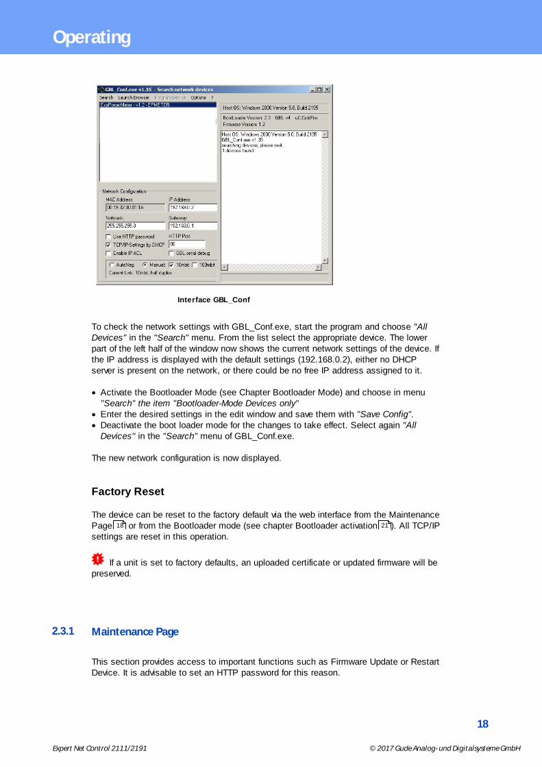
Interface GBL_Conf
To check the network settings with GBL_Conf.exe, start the program and choose "AllDevices" in the "Search" menu. From the list select the appropriate device. The lowerpart of the left half of the window now shows the current network settings of the device. Ifthe IP address is displayed with the default settings (192.168.0.2), either no DHCPserver is present on the network, or there could be no free IP address assigned to it.
· Activate the Bootloader Mode (see Chapter Bootloader Mode) and choose in menu "Search" the item "Bootloader-Mode Devices only"
· Enter the desired settings in the edit window and save them with "Save Config".· Deactivate the boot loader mode for the changes to take effect. Select again "All
Devices" in the "Search" menu of GBL_Conf.exe.
The new network configuration is now displayed.
Factory Reset
The device can be reset to the factory default via the web interface from the MaintenancePage or from the Bootloader mode (see chapter Bootloader activation ). All TCP/IPsettings are reset in this operation.
If a unit is set to factory defaults, an uploaded certificate or updated firmware will bepreserved.
2.3.1 Maintenance Page
This section provides access to important functions such as Firmware Update or RestartDevice. It is advisable to set an HTTP password for this reason.
18 21

19
Expert Net Control 2111/2191 © 2017 Gude Analog- und Digitalsysteme GmbH
Operating
Firmware Update: Start a firmware update.
SSL Certificate Upload: Saves your own SSL certificate. See chapter "SSL " for thegeneration of a certificate in the right format.
Config Import File Upload: Loads a new configuration from a text file. To apply the newconfiguration, a "Restart Device" must be executed after the "Upload".
Config File Export: Saves the current configuration in a text file.
Saving the configuration should only be carried out in an SSL connection, since itcontains sensitive password information (even if it is encrypted or hashed).
Restart Device: Restarts the device without changing the status of the relays.
Some functions such as a firmware update or changing of the IP-address and HTTPsettings require a restart of the device. A jump to the boot loader or a restart of thedevice lead by no means to a change of the relay states.
Restore Fab Settings and Restart Device: Performs a restart and resets the device tofactory default .
Enter Bootloader Mode: Jumps into bootloader mode, where additional settings can bemade with GBL_Conf.exe.
Flush DNS Cache: All entries in the DNS cache are discarded and address resolutionsare requested again.
67
22

20
Expert Net Control 2111/2191 © 2017 Gude Analog- und Digitalsysteme GmbH
Operating
2.3.2 Configuration Management
The device configuration can be saved and restored in the maintenance area .
The "Config File Export" function can be used to save the current configuration as a textfile. The syntax used in the configuration file corresponds to the commands of the Telnetconsole. If the configuration of a device is to be restored from a text file, load the file with"Upload" and restart the device with "Restart Device".
Saving the configuration should only be carried out in an SSL connection, since itcontains sensitive password information (even if it is encrypted or hashed). For the samereasons, it is advisable to carefully handle the generated configuration files when archiv-ing.
Editing the configuration file
It is possible to customize a saved configuration file with a text editor for your ownneeds. For example, one scenario would be to use a script language to automate thecreation of many customized versions of a configuration, then equip a large number ofdevices with an individualized configuration. Also Upload and restart with CGI commandscan be done in scripting languages. With use of the comment sign "#" you can quicklyhide single commands or add personal notes.
If you modify a configuration file manually, it is not always clear which limits are allowedfor parameters. After uploading and restarting, commands with invalid parameters are ig-nored. Therefore, the generated configuration includes comments describing the bound-aries of the parameters. Where "range:" refers to a numeric value, and "len:" to a textparameter. E.g:
email auth set 0 #range: 0..2email user set "" #len: 0..100
The command "system fabsettings" from the beginning of a generated configuration filebrings the device into the factory state, and then executes the individual commands thatmodify the configuration state. It may be desirable to make the changes relative to thecurrent configuration, and not out of the factory state. Then the "system fabsettings"should be removed.
Configuration via Telnet
The configuration files can in principle also be transferred in a Telnet session, but thenthe settings are changed during operation, and not completely when restarting, as itwould have been the case with an upload. It can happen that events are triggered at thesame time as the device is configured. One should therefore:
a) disable the function
18
21
Expert Net Control 2111/2191 © 2017 Gude Analog- und Digitalsysteme GmbH
Operating
b) completely parametrizec) reactivate the function
An example:
email enabled set 0email sender set "" #len: 0..100email recipient set "" #len: 0..100email server set "" #len: 0..100email port set 25email security set 0 #range: 0..2email auth set 0 #range: 0..2email user set "" #len: 0..100email passwd hash set "" #len: 0..100email enabled set 1 #range: 0..1
2.3.3 Bootloader Activation
The configuration of the device from the application "GBL_Conf.exe" is only possible, ifthe device is in Bootloader Mode.
Activation of the Bootloader Mode
1) via push button:
· Hold both buttons for 3 seconds
2) or
· Remove the power supply· Hold down the "Select" button. If the push button is recessed, use a pin or paper clip· Connect the operating voltage
3) by Software: (only if "Enable FW to BL" was previously activated in the"GBL_Conf.exe" application)
· Start the "GBL_Conf.exe" program· Do a network search with the "Search" menu action· Activate in menu "Program Device" the item "Enter Bootloader"
4) via web interface:
Press "Enter Bootloader Mode" on the maintenance web page.
Whether the device is in Bootloader mode, is indicated by the flashing of the statusLED, or it is shown in "GBL_Conf.exe" application after a renewed device search (ap-pendix "BOOT-LDR" after the device name). In Bootloader mode the program"GBL_Conf.exe" can disable the password and the IP ACL, perform a firmware update,and restore the factory settings.
For devices with relays, entering or exiting the bootloader mode does not change thestate of the relays as long as the operating voltage is maintained.
18

22
Expert Net Control 2111/2191 © 2017 Gude Analog- und Digitalsysteme GmbH
Operating
Abandonment of the Bootloader Mode
1) via push button:
· Hold both buttons for 3 seconds (only if the device has 2 buttons)
2) or
· Remove and connect the power supply without operating a button
3) by Software:
· Start the "GBL_Conf.exe" application· Do a network search with the "Search" menu action· In menu "Program Device" activate the item "Enter Firmware"
Factory Reset
If the device is in bootloader mode, it can always be put back to its factory default. AllTCP/IP settings are reset in this operation.
If a unit is set to factory defaults, an uploaded certificate or updated firmware will bepreserved.
1) via push button:
· Activate the Bootloader Mode of the device· Hold down the button (or the "Select" button for devices with 2 buttons) for 6 seconds.
If the push button is recessed, use a pin or paper clip· The status LED will blink in a fast rhythm, please wait until the LED blinks slowly
(about 5 seconds)
2) by Software:
· Activate the Bootloader Mode of the device· "Start the GBL_Conf.exe" program· In menu "Program Device" activate the item "Reset to Fab Settings"· The status LED will blink in a fast rhythm, please wait until the LED blinks slowly
(about 5 seconds)
2.4 GSM
To use the GSM functions, there must be an activated SIM card in the SIM card slot.
If the SIM card is inserted, and the device is enabled, the integrated GSM modulesearches automatically for a connection to the GSM network. If this connection works,you can control and configure the device via SMS or by call.
When operating via SMS, send defined SMS commands to the device. The device ex-ecutes these commands and confirms them with reply SMS.
23
Expert Net Control 2111/2191 © 2017 Gude Analog- und Digitalsysteme GmbH
Operating
When operating via phone call, you can perform commands by FreeCall, that allow theunit to perform preconfigured commands, when it is called from a particular phone num-ber. There is no connection established and there are no call charges. Another possibil-ity is the voice call. Here, the device menu is operated using DTMF codes. This type ofoperation can also be carried out automatically.
Preparing for GSM operation
If you are using a new SIM card, please take note:
1. Preparing the SIM card· If you are using a contracted SIM card, please start with step 2· If you are using a prepaid SIM card, please take care:
o There has to be a positiv balance on the card
o The card has to be activated. New prepaid cards need some
manual operation at the start of usage. These requests have to bemade from a user with a cellphone.
2. SIM-card pin code· The device awaits the SIM card pin code 1234 first. Enter this PIN to the
SIM card, by using a cellphone. In case you are using another pin code,you have to configure the EPC NET GSM before you activate the GSMpart of the device! Otherwise this may lead to a lock of the SIM card.
· You can disable the need to enter the PIN code on the SIM card with amobile phone. In this case the EPC NET GSM accepts the SIM cardwithout checking the code.
3. Install SIM card· Switch off the device or deactivate the GSM module. Alternatively, you
can just turn off the GSM module in the EPC NET GSM via software.Never install a SIM card, when GSM module is active. Otherwise the SIMcard may be destroyed.
· Insert the SIM card into the Push Sim Holder.
4. Connect Antenna· Take the GSM antenna from the box and screw it to the EPC NET GSM
by turning clockwise. It is enough to attract the connection hand-tight.Never use pliers to tighten or similar to the antenna, thus inevitably des-troying the antenna connection.
5. Activate the EPC NET GSM· Power up the device. In factory default state, the GSM module is deactiv-
ated. This is a security setting in delivery to avoid accidentally locking aSIM card with the wrong code.
· Log in on the web interface. · Switch to Configuration / GSM / SIM.· Here the button "Enable GSM" is set to "No", that is the GSM module is
turned off. Set the button to "yes", then press the button "Apply" to trans-mit the data to the EPC NET GSM.
· Wait some minutes, until the device has logged into the GSM. You cansee the status change from the Signal Tower indicator LED on the displayor in the web interface.
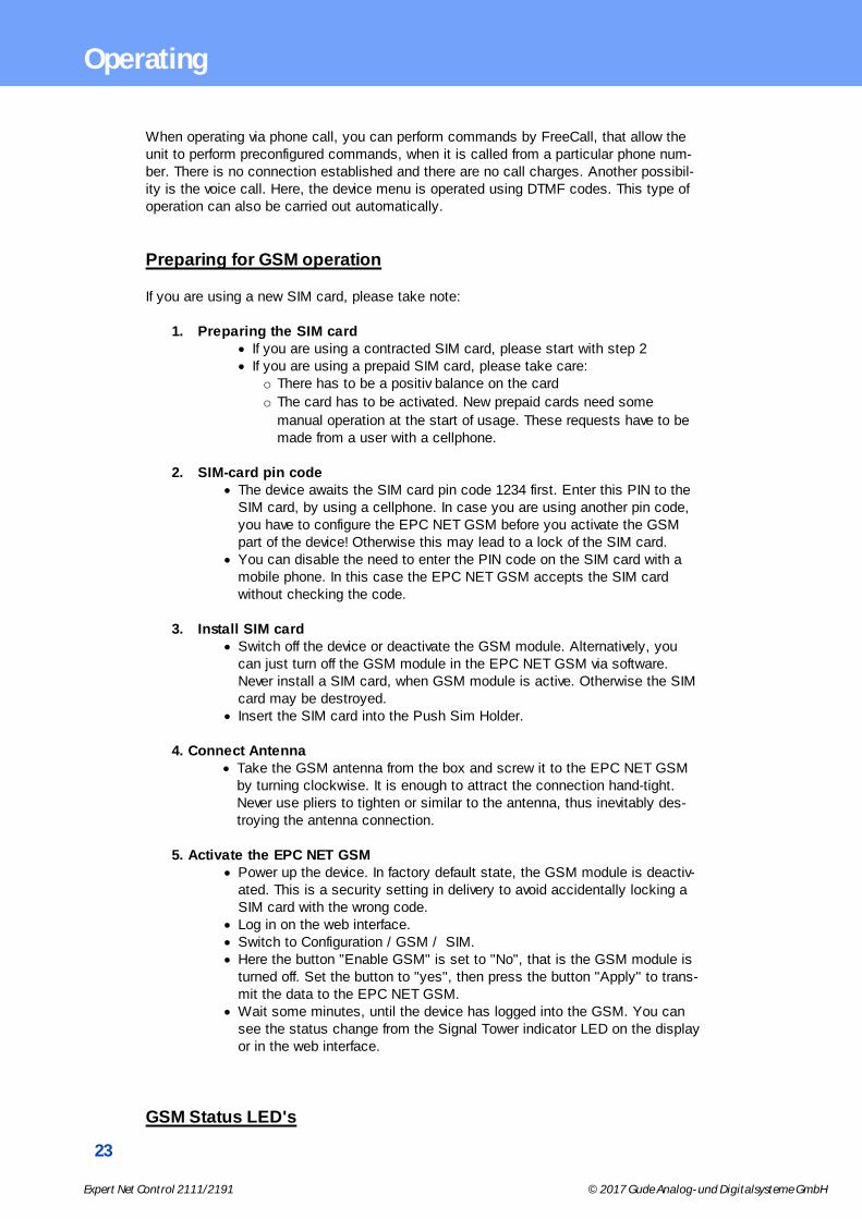
GSM Status LED's

24
Expert Net Control 2111/2191 © 2017 Gude Analog- und Digitalsysteme GmbH
Operating
The GSM status LED's displays different states of the GSM module.
Signal Tower indicator offGSM module is deactivated.
Signal Tower indicator onGSM module activated.
Signal Strength Indicator· 0 bars - no signal· 2 bars - approx. 30%· 4 bars - approx. 70%· 6 bars - approx. 100%
2.4.1 SMS
2.4.1.1 SMS Commands
Description of the SMS format to send commands to the device:
Format
%[cmd-name] [param 1] [...] [param N] {param 1} {...} {param N} [param x] = mandatory parameter {param x} = optional paramater
If activated, a port code or master code will be required. Entering these codes is initiatedby p (for Port code) or m (for Master code).
2.4.1.1.1 Port: Query Port State
Format
%port state [portnumber] {Portcode/Mastercode}
Command:
Request of status of Output Port 1, Portcode 1111%port state 1 p1111
Answer: Hostname: ENC-2191Output Port state: Port 1 is OffCredit: 130.50 EurSensor 1: N.C.Sensor 2: N.C.Sensor 3: N.C.Temp. 4: 25.8 C
2.4.1.1.2 Port: Simple Switching
Format

25
Expert Net Control 2111/2191 © 2017 Gude Analog- und Digitalsysteme GmbH
Operating
%port [on, off, toggle] [portnumber] {Portcode/Mastercode}
Examples:
Switch off Output Port 2, Mastercode 2222%port off 2 m2222
Toggle Output Port 8, Portcode 1238%port toggle 8 p1238
Reset Output Port 6, Portcode 0123%port reset 6 p0123
Switch on Output Port 1, without Portcode%port on 1
Answer (example): Device name: epc007Port switch: Port 1 off -> on Account Credit: Credit: 130.50 Eur
2.4.1.1.3 Port: Advanced Switching (Batchmode)
Format
%port batchmode [portnumber] [batch-sequence-number] {Portcode/Mastercode}
[batch-sequence-number] '11' .. '19' off, wait [t1 .. t9]s, on'21' .. '29' on, wait [t1 .. t9]s, off '31' .. '39' toggle, wait [t1 .. t9]s, toggle
Note: Sequence numbers are identical to the DTMF codes for voice calls.
tn Time in seconds
t1 1
t2 2
t3 5
t4 10
t5 20
t6 60
t7 120
t8 240
t9 480
Example: %port batchmode 1 13 m0123
Answer: Device name: epc007Switch sequence: Port 1 off -> t3 -> on
26
Expert Net Control 2111/2191 © 2017 Gude Analog- und Digitalsysteme GmbH
Operating
Account Credit: Credit 130.50
2.4.1.1.4 Port: Advanced Switching (coldstart)
The command 'coldstart' turns off all Output Ports at once. Then it switches the portstemporally delayed on again (according to the current output port configuration), as if thedevice performs a cold start.
Format
%coldstart {mastercode}
Example: %coldstart m0123
Answer: Device name: epc007Switch sequence: coldstartAccount Credit: Credit: 130.50 Eur
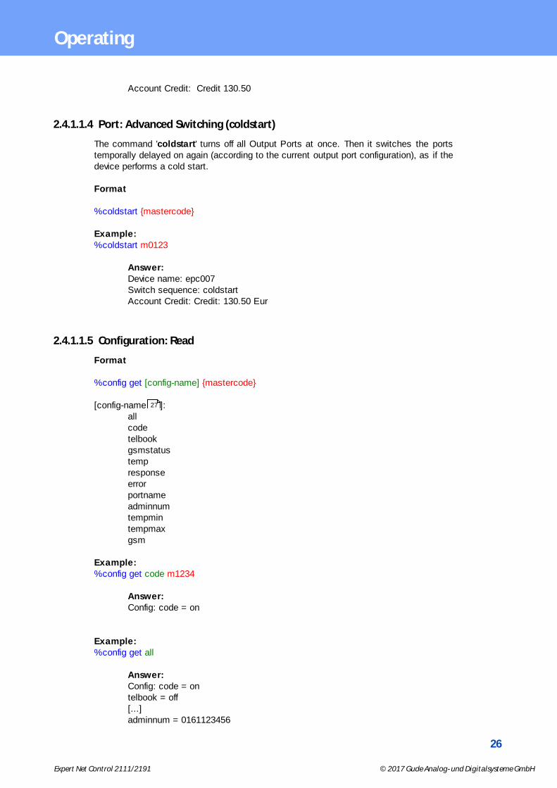
2.4.1.1.5 Configuration: Read
Format
%config get [config-name] {mastercode}
[config-name ]:allcodetelbookgsmstatustempresponseerrorportnameadminnumtempmintempmaxgsm
Example: %config get code m1234
Answer: Config: code = on
Example: %config get all
Answer: Config: code = ontelbook = off[...]adminnum = 0161123456
27

27
Expert Net Control 2111/2191 © 2017 Gude Analog- und Digitalsysteme GmbH
Operating
gsm = on
2.4.1.1.6 Configuration: Write
Format
%config set [config-name] [config-value] {Mastercode}
[config-name] :codetelbookgsmstatustempresponseerrorportnameadminnumtempmintempmaxgsm
Example: %config set code off m1234
Answer: Config: code = off
2.4.1.1.7 Configuration: All Parameter
Description SMS [config-name] SMS [config-value] default
Master/Port Codeenabled?
code on, off off
Check of phonebook?
telbook on, off off
Send GSMStatus SMS to 'adminnum'
gsmstatus on, off off
Send SMS to 'ad-minnum' if temp-min / tempmaxare changed
temp on, off off
Send SMS replyon SMS com-mands to recentSMS user
response on, off on
Send SMS replywith error mes-sage, if SMScommand wasmalformed
error on, off on
27

28
Expert Net Control 2111/2191 © 2017 Gude Analog- und Digitalsysteme GmbH
Operating
Description SMS [config-name] SMS [config-value] default
States configuredPort name in-stead of OutputPort n in SMSreplies
portname on, off off
Allow deactivationof GSM modulevia SMS
gsm on, off off
Phone number fore-mail messages
email max. 15 chars
Access only foradmin
mastergsm on, off off
Autosync autosync on, off off
DTMF forVoiceCall
calltone on, off off
Voice forVoiceCall
callvoice on, off on
Phone number forSMS messages
adminnum max. 15 chars
Minimum valuefor temperaturealerts
tempmin '-20' .. '0' 0
Maximum valuefor temperaturealerts
tempmax '0' .. '90' 50
Allows freecalloperation
freecall on, off off
2.4.1.1.8 Sensors: Query State
Format
%sensor state [portnumber, all] {Mastercode}
Example:
Query the state of all sensors, Mastercode 0000%sensor state m0000
Answer: Device name: epc007Port: Sensor port 1Sensor name: TemperatureValue: NCPort: Sensor port 2Sensor name: TemperatureValue: T=22.79CValue: RH= 76.64%Account credit: Credit: 130.50 Eur

29
Expert Net Control 2111/2191 © 2017 Gude Analog- und Digitalsysteme GmbH
Operating
2.4.1.1.9 Query Device State
Format
%all state {Mastercode}
Example:
Query the state of the device:%all state
Answer: Device name: epc007: StatusOutputport state: outp: 1=On 2=On 3=On 4=OffInputport state: dinp: 1=Off 2=Off 3=Off 4=OffSensor Port 1: senp 1: NCSensor Port 2: senp 2: T=22.79C RH= 76.64%Account credit: Credit: 130.50 Eur
2.4.1.2 SMS replies
2.4.1.2.1 SMS command replies
A command reply SMS looks like:
Device name: [name] prefix
[response text] Command specific reply
Account credit: [x]
[response text]
Device name: [name]
Port switch: [port] [s] -> [s] [port] = Port 1 .. Port 99 (or Config:portname) [s] = on .. off
Port state: [port] is [s], [...], [port] is [s] [port] = Port 1 .. Port 99 (or Config:portname) [s] = on .. off
Switch sequence: [s][s]
[port] [c] -> wait t -> [c][port] = 'Port 1' .. 'Port 99' (or Config:portname) [c] = on, off, toggle, coldstart
Account credit: [x]
Config: name = value, [...], name = value

30
Expert Net Control 2111/2191 © 2017 Gude Analog- und Digitalsysteme GmbH
Operating
or
command parse error
2.4.1.2.2 Status Change Report SMS
A SMS status change request reply looks like:
Device name: [name] Prefix
[response text] Status change request specific reply
Account credit: [x]
[response text]
Device name: [name]
[port] -> [s] [port] = 'Port 1' .. 'Port 99' (or Config:portname) [s] = 'on' .. 'off'
[port] [s] [port] = 'Port 1' .. 'Port 99' (or Config:portname) [s] = batchmode, toggled, Coldstart
Temperature state: [val][val] = 'over the MAX limit', 'under the MIN limit'
Account credit: [x]
2.4.2 Voice Call
2.4.2.1 Menu
For operating with VoiceCall, simply call the phone number of the SIM card of the GSMmodule. When connection is established the device replies with the announcement:"Main menu" and a DTMF toneIn the menu the navigation works via DTMF commands.
Each command starts with # and ends with *.
Numbers Men
*1# Output Port
*2# Input Port
*8# Status
You can combine multiple commands into a command. Just type the commands oneafter another and terminate it as a whole with #.

31
Expert Net Control 2111/2191 © 2017 Gude Analog- und Digitalsysteme GmbH
Operating
*[Command 1][Command 2]...[Command n]#
Some commands may require the Port or MasterCode. These codes have to be addedat end of the command
Eample:
Navigate from Main Menu into the Status Menu using mastercode 1111
*8# - enter Status Menu1111 - Mastercode
For the navigation in menus the following commands are required:
*99# - Jump to Main Menu*98# - Return to prev Menu*97# - Help
32
Expert Net Control 2111/2191 © 2017 Gude Analog- und Digitalsysteme GmbH
Operating
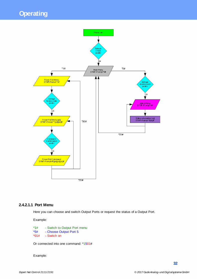
2.4.2.1.1 Port Menu
Here you can choose and switch Output Ports or request the status of a Output Port.
Example:
*1# - Switch to Output Port menu*5# - Choose Output Port 5*01# - Switch on
Or connected into one command: *1501#
Example:

33
Expert Net Control 2111/2191 © 2017 Gude Analog- und Digitalsysteme GmbH
Operating
*7# - Choose Output Port 7*23# - Activate Batchmode No.23 for Output Port 7 - Output Portt 7 on, wait t3, off
Example:
*3# - Choose Output Port 3*03# - Request state of Output Port 4
Or as one command: *303#
Please check the Output Port commands [pc] for further information
2.4.2.1.2 Status Menu
Different states of the device can be requested
*00# Value of the account of the PrePaid card
*01# Request of an SMS with all output port information, announcement"SMS sent"
*03# Request of an SMS with configuration information, announcement"SMS sent"
*04# Request of actual sensor information (a sensor has to be connected)
*10# Request of the state of all Output Ports
2.4.2.1.3 Parameter Description
[pn]Output Port Number - Values: '1' .. '9'
[ps] - Output Port State - Values: '0' .. '1' (on/off)
[pc] - Output Port Command - Values: '00' .. '89'
[in] - Input-Port Number - Values: '1' .. '9'
[is] - Input-Port State - Values: '0' .. '1' (on/off)
[sq] - Status Query
34
Expert Net Control 2111/2191 © 2017 Gude Analog- und Digitalsysteme GmbH
Operating
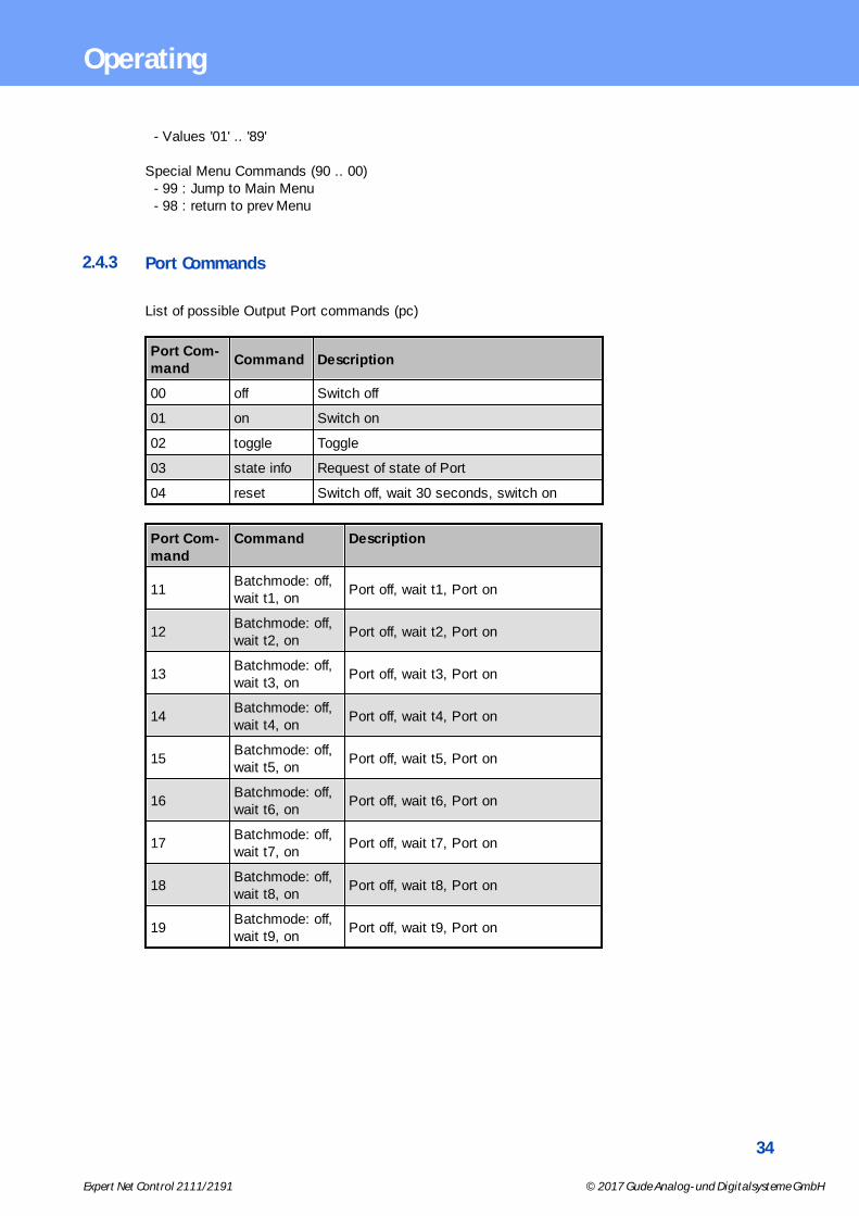
- Values '01' .. '89'
Special Menu Commands (90 .. 00) - 99 : Jump to Main Menu - 98 : return to prev Menu
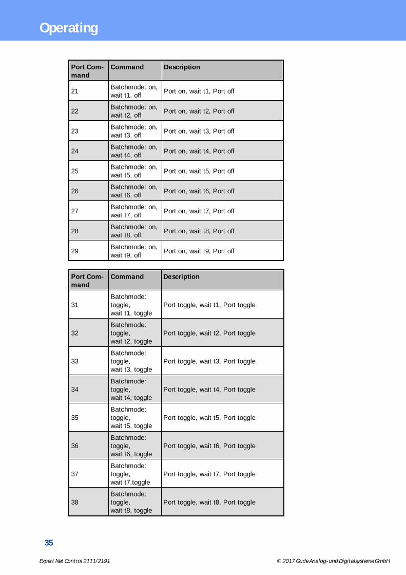
2.4.3 Port Commands
List of possible Output Port commands (pc)
Port Com-mand
Command Description
00 off Switch off
01 on Switch on
02 toggle Toggle
03 state info Request of state of Port
04 reset Switch off, wait 30 seconds, switch on
Port Com-mand
Command Description
11Batchmode: off, wait t1, on
Port off, wait t1, Port on
12Batchmode: off, wait t2, on
Port off, wait t2, Port on
13Batchmode: off, wait t3, on
Port off, wait t3, Port on
14Batchmode: off, wait t4, on
Port off, wait t4, Port on
15Batchmode: off, wait t5, on
Port off, wait t5, Port on
16Batchmode: off, wait t6, on
Port off, wait t6, Port on
17Batchmode: off, wait t7, on
Port off, wait t7, Port on
18Batchmode: off, wait t8, on
Port off, wait t8, Port on
19Batchmode: off, wait t9, on
Port off, wait t9, Port on
35
Expert Net Control 2111/2191 © 2017 Gude Analog- und Digitalsysteme GmbH
Operating
Port Com-mand
Command Description
21Batchmode: on, wait t1, off
Port on, wait t1, Port off
22Batchmode: on, wait t2, off
Port on, wait t2, Port off
23Batchmode: on, wait t3, off
Port on, wait t3, Port off
24Batchmode: on, wait t4, off
Port on, wait t4, Port off
25Batchmode: on, wait t5, off
Port on, wait t5, Port off
26Batchmode: on, wait t6, off
Port on, wait t6, Port off
27Batchmode: on, wait t7, off
Port on, wait t7, Port off
28Batchmode: on, wait t8, off
Port on, wait t8, Port off
29Batchmode: on, wait t9, off
Port on, wait t9, Port off
Port Com-mand
Command Description
31Batchmode:toggle, wait t1, toggle
Port toggle, wait t1, Port toggle
32Batchmode:toggle, wait t2, toggle
Port toggle, wait t2, Port toggle
33Batchmode:toggle, wait t3, toggle
Port toggle, wait t3, Port toggle
34Batchmode:toggle, wait t4, toggle
Port toggle, wait t4, Port toggle
35Batchmode:toggle, wait t5, toggle
Port toggle, wait t5, Port toggle
36Batchmode:toggle, wait t6, toggle
Port toggle, wait t6, Port toggle
37Batchmode:toggle, wait t7,toggle
Port toggle, wait t7, Port toggle
38Batchmode:toggle, wait t8, toggle
Port toggle, wait t8, Port toggle
36
Expert Net Control 2111/2191 © 2017 Gude Analog- und Digitalsysteme GmbH
Operating
Port Com-mand
Command Description
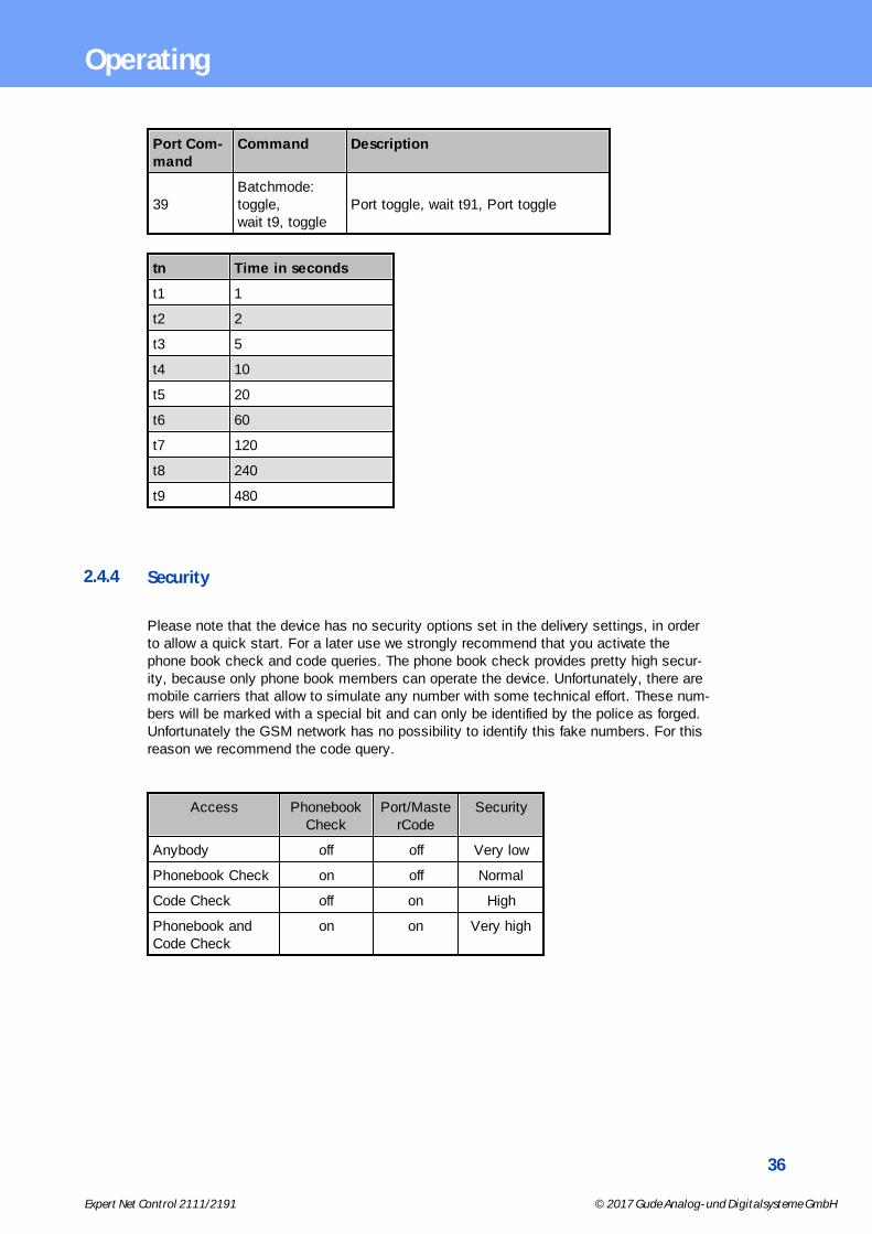
39Batchmode:toggle, wait t9, toggle
Port toggle, wait t91, Port toggle
tn Time in seconds
t1 1
t2 2
t3 5
t4 10
t5 20
t6 60
t7 120
t8 240
t9 480
2.4.4 Security
Please note that the device has no security options set in the delivery settings, in orderto allow a quick start. For a later use we strongly recommend that you activate thephone book check and code queries. The phone book check provides pretty high secur-ity, because only phone book members can operate the device. Unfortunately, there aremobile carriers that allow to simulate any number with some technical effort. These num-bers will be marked with a special bit and can only be identified by the police as forged.Unfortunately the GSM network has no possibility to identify this fake numbers. For thisreason we recommend the code query.
Access PhonebookCheck
Port/MasterCode
Security
Anybody off off Very low
Phonebook Check on off Normal
Code Check off on High
Phonebook andCode Check
on on Very high
Configuration
38
Expert Net Control 2111/2191 © 2017 Gude Analog- und Digitalsysteme GmbH
Configuration
3 Configuration
TCP/IP configuration by DHCP
After switching on the device is scanning on the Ethernet for a DHCP server and re-quests an unused IP address. Check the IP address that has been assigned and adjustif necessary, that the same IP address is used at each restart. To turn off DHCP use thesoftware GBL_Conf.exe or use the configuration via the web interface.
To check the network settings with GBL_Conf.exe, start the program and choose "AllDevices" in the "Search" menu. From the list select the appropriate device. The lowerpart of the left half of the window now shows the current network settings of the device. Ifthe IP address is displayed with the default settings (192.168.0.2), either no DHCPserver is present on the network, or there could be no free IP address assigned to it.
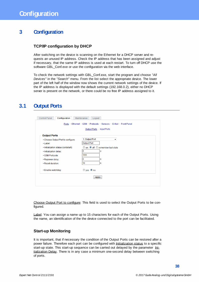
3.1 Output Ports
Choose Output Port to configure: This field is used to select the Output Ports to be con-figured.
Label: You can assign a name up to 15 characters for each of the Output Ports. Usingthe name, an identification of the the device connected to the port can be facilitated.
Start-up Monitoring
It is important, that if necessary the condition of the Output Ports can be restored after apower failure. Therefore each port can be configured with Initialization status to a specificstart-up state. This start-up sequence can be carried out delayed by the parameter Ini-tialization Delay. There is in any case a minimum one-second delay between switchingof ports.
39
Expert Net Control 2111/2191 © 2017 Gude Analog- und Digitalsysteme GmbH
Configuration
Initialization status(coldstart): This is the port state (on, off, remember last state) theport should be set when the device is turned on. The setting "remember last state" savesthe last manually set state of the Output Port in the EEPROM.
Initialization delay: Here can be configured how long the port should wait to switch to itsdefined state after the device is turned on. The delay may last up to 8191 seconds. Thiscorresponds to a period of approx. two hours and 20 minutes. A value of zero meansthat the initialization is off.
GSM Portcode (only ENC 2191): Sets the individual port access code.
Repower delay: When this feature is enabled (value greater than 0), the Output Port willswitch itself on again a specified time after it has been disabled. Unlike the "Reset" but-ton this function applies to all switch actions, including SNMP, or an optional serial inter-face.
Reset Duration: When the "Reset" button is triggered, the device turns the Output Portoff, waits for the time entered here (in seconds) and turns the Output Port on.
3.1.1 Watchdog
The watchdog feature enables to monitor various remote devices. Therefore either ICMPpings or TCP pings are sent to the device to be monitored. If these pings are notanswered within a certain time (both the time and the number of attempts can be set),the port is reset. This allows e.g. to automatically restart not responding server or NASsystems. The mode IP master-slave port allows you to switch a port depending on theavailability of a remote device.
When a watchdog is activated it presents various information in the Control Panel. Theinformation is color-coded.
· Green text: The watchdog is active and regularly receives ping replies.· Orange text: The watchdog is currently enabled, and waits for the first Ping response.· Red text: The watchdog is active and receives no ping replies anymore from the con-
figured IP address.
After the watchdog has been enabled, the display remains orange until the watchdog re-ceives a ping response for the first time. Only then the watchdog is activated. Even aftertriggering a watchdog and a subsequent Output Port reset, the display will remain or-ange until the device is rebooted and responds again to ping requests. This will prevent apremature watchdog reset of the port, e.g. when a server needs a long time for a filecheck.
You can monitor devices on your own network, as well as devices on an external net-work, e.g. the operating status of a router.

40
Expert Net Control 2111/2191 © 2017 Gude Analog- und Digitalsysteme GmbH
Configuration
Enable watchdog: Enables the watchdog function for this Output Port.
Watchdog type: Here you can choose between the monitoring by ICMP pings or TCPpings.
· ICMP Pings: The classic ping (ICMP echo request). It can be used to check the ac-cessibility of network devices (for example, a server).
· TCP Pings: With TCP pings, you can check if a TCP port on the target device wouldaccept a TCP connect. Therefore a non-blocked TCP port should be selected. A goodchoice would be port 80 for http or port 25 for SMTP.
TCP port: Enter the TCP port to be monitored. When using ICMP pings this is notneeded.
Hostname: The name or IP address of the monitored network device.
Ping interval: Select the frequency (in seconds) at which the ping packet is sent to eachnetwork device to check its operating status.
Ping retries: After this number of consecutive unanswered ping requests the device isconsidered inactive.
Watchdog mode: When Reset port when host down is enabled, the Output Port isturned off and switched back on after the time set in Reset Duration. In mode Switch offonce when host down the Output Port remains disabled.
At the default setting (Infinite wait for booting host after reset) the watchdog monitors theconnected device. When there is no longer a reply after a set time, the watchdog per-forms the specified action, usually a reset of the Output Port. Now the watchdog waitsuntil the monitored device reports again on the network. This may take several minutesdepending on the boot duration of the device. Only when the device is accessible fromnetwork again, the watchdog is re-armed. If the option Repeat reset on booting host afterx ping timeout is enabled, this mechanism is bypassed. Now the watchdog is re-activ-ated after N Ping intervals (input field ping timeouts).
When enabling the IP master-slave mode, the port is switched depending on the availab-ility of a remote device. Depending on the configuration, the port is switched on when theterminal is reachable, or vice versa.
41
Expert Net Control 2111/2191 © 2017 Gude Analog- und Digitalsysteme GmbH
Configuration
The option Repeat reset on booting host after x ping timeout has the following pitfall:If a server, that is connected to the monitored Port is in need for a long boot process(e.g. it is doing a file system check), the server would probably exceed the tripping timeof the watchdog. The server would be switched off and on again, and the file systemcheck is restarted. This would be repeated endlessly.
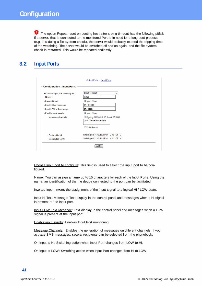
3.2 Input Ports
Choose Input port to configure: This field is used to select the input port to be con-figured.
Name: You can assign a name up to 15 characters for each of the Input Ports. Using thename, an identification of the the device connected to the port can be facilitated.
Inverted Input: Inverts the assignment of the input signal to a logical HI / LOW state.
Input HI Text Message: Text display in the control panel and messages when a HI signalis present at the input port.
Input LOW Text Message: Text display in the control panel and messages when a LOWsignal is present at the input port.
Enable input events: Enables Input Port monitoring.
Message Channels: Enables the generation of messages on different channels. If youactivate SMS messages, several recipients can be selected from the phonebook.
On input is HI: Switching action when Input Port changes from LOW to HI.
On input is LOW: Switching action when Input Port changes from HI to LOW.

42
Expert Net Control 2111/2191 © 2017 Gude Analog- und Digitalsysteme GmbH
Configuration
3.3 Ethernet
3.3.1 IP Address
Hostname: Here you can enter a name with up to 63 characters. This name will be usedfor registration on the DHCP server.
Special characters and umlauts can cause problems in the network.
IPv4 Address: The IP address of the device.
IPv4 Netmask: The network mask used in the network.
IPv4 Gateway address: The IP address of the gateway.
IPv4 DNS address: The IP address of the DNS server.
Use IPv4 DHCP: Select "yes" if the TCP/IP settings should be obtained directly from theDHCP server: When the function is selected, each time the device powers up it ischecked if a DHCP server is available on the network. If not, the last used TCP/IP settingwill be used further.
Use IPv6 Protocol: Activates IPv6 usage.
Use IPv6 Router Advertisement: The Router Advertisement communicates with the routerto make global IPv6 addresses available.
Use DHCP v6: Requests from an existing DHCPv6 server addresses of the configuredDNS server.
Use manual IPv6 address settings: Activates the entry of manual IPv6 addresses.
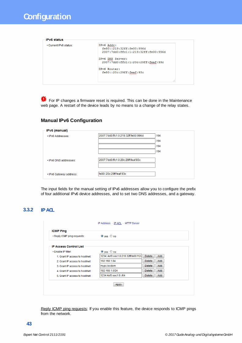
IPv6 status: Displays the IPv6 addresses over which the device can be accessed, andadditionally DNS and router addresses.
43
Expert Net Control 2111/2191 © 2017 Gude Analog- und Digitalsysteme GmbH
Configuration
For IP changes a firmware reset is required. This can be done in the Maintenanceweb page. A restart of the device leads by no means to a change of the relay states.
Manual IPv6 Configuration
The input fields for the manual setting of IPv6 addresses allow you to configure the prefixof four additional IPv6 device addresses, and to set two DNS addresses, and a gateway.
3.3.2 IP ACL
Reply ICMP ping requests: If you enable this feature, the device responds to ICMP pingsfrom the network.
44
Expert Net Control 2111/2191 © 2017 Gude Analog- und Digitalsysteme GmbH
Configuration
Enable IP filter: Enable or disable the IP filter here. The IP filter represents an accesscontrol for incoming IP packets.
Please note that when IP access control is enabled HTTP and SNMP only work ifthe appropriate servers and clients are registered in the IP access control list.
If you choose a wrong IP ACL setting and locked yourself out, please activate theBootloader Mode and use GBL_Conf.exe to deactivate the IP ACL. Alternatively, youcan reset the device to factory default.
3.3.3 HTTP
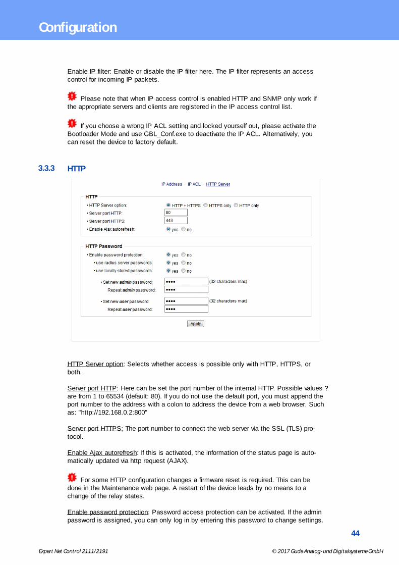
HTTP Server option: Selects whether access is possible only with HTTP, HTTPS, orboth.
Server port HTTP: Here can be set the port number of the internal HTTP. Possible values ??are from 1 to 65534 (default: 80). If you do not use the default port, you must append theport number to the address with a colon to address the device from a web browser. Suchas: "http://192.168.0.2:800"
Server port HTTPS; The port number to connect the web server via the SSL (TLS) pro-tocol.
Enable Ajax autorefresh: If this is activated, the information of the status page is auto-matically updated via http request (AJAX).
For some HTTP configuration changes a firmware reset is required. This can bedone in the Maintenance web page. A restart of the device leads by no means to achange of the relay states.
Enable password protection: Password access protection can be activated. If the adminpassword is assigned, you can only log in by entering this password to change settings.

45
Expert Net Control 2111/2191 © 2017 Gude Analog- und Digitalsysteme GmbH
Configuration
Users can log in by entering the user password in order to query the status informationand initiate switching operations.
Use radius server passwords: Username and password are validated by a Radius Sever.
Use locally stored passwords: Username and password are stored locally. In this case,an admin password and a user password must be assigned. The password can have amaximum of 31 characters. The name "admin" and "user" are provided for the user namein the password entry mask of the browser. In factory settings, the password for the ad-min is set to "admin" or "user" for the user password.
If the password mask is redisplayed, only four "bullets" are shown as a symbolicplaceholder, since for security reasons the device never stores the password itself, butonly the SHA2-256 hash. If you want to change a password, the complete passwordmust always be re-entered.
If you have forgotten your password, please activate the bootloader mode and thenturn off the password prompt in GBL_Conf.exe.
3.4 Protocols
3.4.1 Console
Enable Telnet: Enables Telnet console .
Telnet TCP port: Telnet sessions are accepted on this port.
Raw mode: The VT100 editing and the IAC protocol are disabled.
Activate echo: The echo setting if not changed by IAC.
Active negotiation: The IAC negotiation is initiated by the server.
46
Expert Net Control 2111/2191 © 2017 Gude Analog- und Digitalsysteme GmbH
Configuration
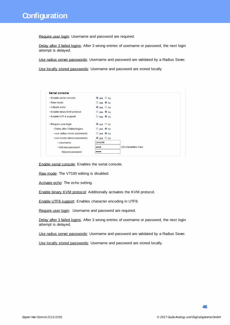
Require user login: Username and password are required.
Delay after 3 failed logins: After 3 wrong entries of username or password, the next loginattempt is delayed.
Use radius server passwords: Username and password are validated by a Radius Sever.
Use locally stored passwords: Username and password are stored locally
Enable serial console: Enables the serial console.
Raw mode: The VT100 editing is disabled.
Activate echo: The echo setting.
Enable binary KVM protocol: Additionally activates the KVM protocol.
Enable UTF8 support: Enables character encoding in UTF8.
Require user login: Username and password are required.
Delay after 3 failed logins: After 3 wrong entries of username or password, the next loginattempt is delayed.
Use radius server passwords: Username and password are validated by a Radius Sever.
Use locally stored passwords: Username and password are stored locally.
47
Expert Net Control 2111/2191 © 2017 Gude Analog- und Digitalsysteme GmbH
Configuration
3.4.2 Syslog
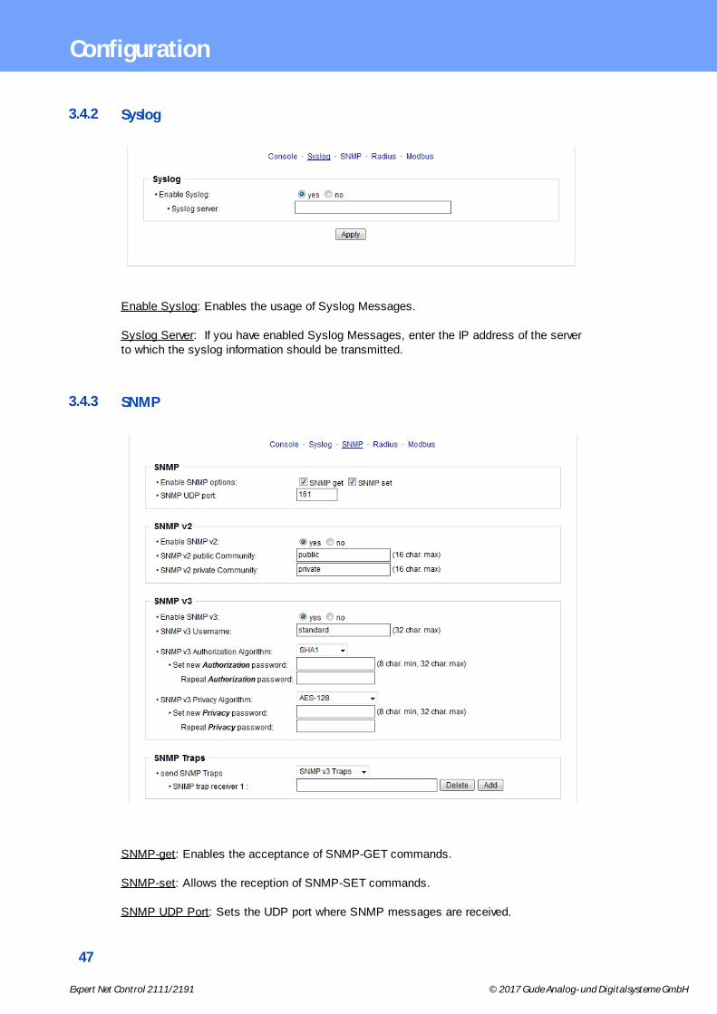
Enable Syslog: Enables the usage of Syslog Messages.
Syslog Server: If you have enabled Syslog Messages, enter the IP address of the serverto which the syslog information should be transmitted.
3.4.3 SNMP
SNMP-get: Enables the acceptance of SNMP-GET commands.
SNMP-set: Allows the reception of SNMP-SET commands.
SNMP UDP Port: Sets the UDP port where SNMP messages are received.

48
Expert Net Control 2111/2191 © 2017 Gude Analog- und Digitalsysteme GmbH
Configuration
Enable SNMP v2: Activates SNMP v2.
Because of security issues, it is advisable to use only SNMP v3, and to disableSNMP v2. Accesses to SNMP v2 are always insecure.
Community public: The community password for SNMP GET requests.
Community private: The community password for SNMP SET requests.
Enable SNMP v3: Activates SNMP v3.
SNMP v3 Username: The SNMP v3 User Name.
SNMP v3 Authorization Algorithm: The selected Authentication Algorithm.
SNMP v3 Privacy Algorithm: SNMP v3 Encryption Algorithm..
If the password mask is redisplayed, only four "bullets" are shown as a symbolicplaceholder, since for security reasons the device never stores the password itself, butonly the key formed using the Authorization Algorithm. If you want to change a pass-word, the complete password must always be re-entered.
The calculation of the password hashes varies with the selected algorithms. If theAuthentication or Privacy algorithms are changed, the passwords must be re-entered inthe configuration dialog. "SHA-384" and "SHA512" are calculated purely in software. If"SHA-512" is set on the configuration page, the time for the key generation may takeonce up to approx. 45 seconds.
Send SNMP traps: Here you can specify whether, and in what format the device shouldsend SNMP traps.
SNMP trap receiver: You can insert here up to eight SNMP trap receiver.
MIB table: The download link to the text file with the MIB table for the device.
More information about SNMP settings are available from our support or can be found onthe Internet at www.gude.info/wiki.
49
Expert Net Control 2111/2191 © 2017 Gude Analog- und Digitalsysteme GmbH
Configuration
3.4.4 Radius
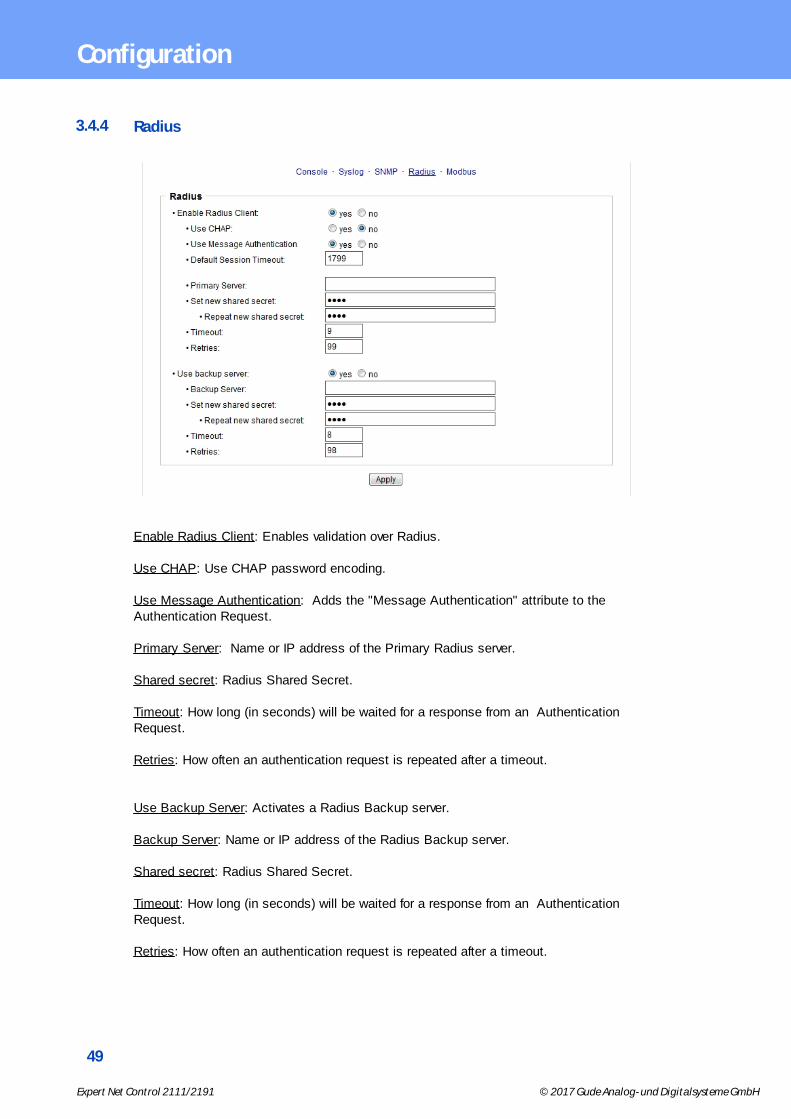
Enable Radius Client: Enables validation over Radius.
Use CHAP: Use CHAP password encoding.
Use Message Authentication: Adds the "Message Authentication" attribute to theAuthentication Request.
Primary Server: Name or IP address of the Primary Radius server.
Shared secret: Radius Shared Secret.
Timeout: How long (in seconds) will be waited for a response from an AuthenticationRequest.
Retries: How often an authentication request is repeated after a timeout.
Use Backup Server: Activates a Radius Backup server.
Backup Server: Name or IP address of the Radius Backup server.
Shared secret: Radius Shared Secret.
Timeout: How long (in seconds) will be waited for a response from an AuthenticationRequest.
Retries: How often an authentication request is repeated after a timeout.
50
Expert Net Control 2111/2191 © 2017 Gude Analog- und Digitalsysteme GmbH
Configuration
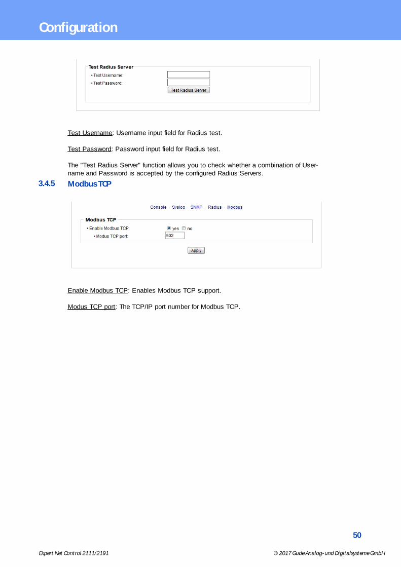
Test Username: Username input field for Radius test.
Test Password: Password input field for Radius test.
The "Test Radius Server" function allows you to check whether a combination of User-name and Password is accepted by the configured Radius Servers.
3.4.5 Modbus TCP
Enable Modbus TCP: Enables Modbus TCP support.
Modus TCP port: The TCP/IP port number for Modbus TCP.

51
Expert Net Control 2111/2191 © 2017 Gude Analog- und Digitalsysteme GmbH
Configuration
3.5 Sensors
Choose sensor port: Selects a type of sensor to configure it. The first digit "1" indicatesthe number of the sensor port (only important for devices with more than one sensorport). This is followed by the sensor name (e.g. 7002 for the hybrid sensor), a letter forthe sub-type sensor and the changeable sensor name. The sensor subtypes are definedas: "T" = temperature, "H" = humidity, "I" = sensor input.
Sensor Name: Changeable name for this sensor. Temperature and humidity can have dif-ferent names, even if they are from the same sensor.
Enable sensor events: Enables the generation of sensor messages.
Maximum/Minimum value: Here you can choose whether, and at what Maximum/Min-imum temperature or humidity measurements limits the alerts are send via SNMP traps,syslog or E-Mail.
Hysteresis: This describes the margin of when an event is generated after the measuredvalue has crossed the chosen limit.
Message channels: Enables the generation of messages on different channels. If youactivate SMS messages, several recipients can be selected from the phonebook.
52
Expert Net Control 2111/2191 © 2017 Gude Analog- und Digitalsysteme GmbH
Configuration
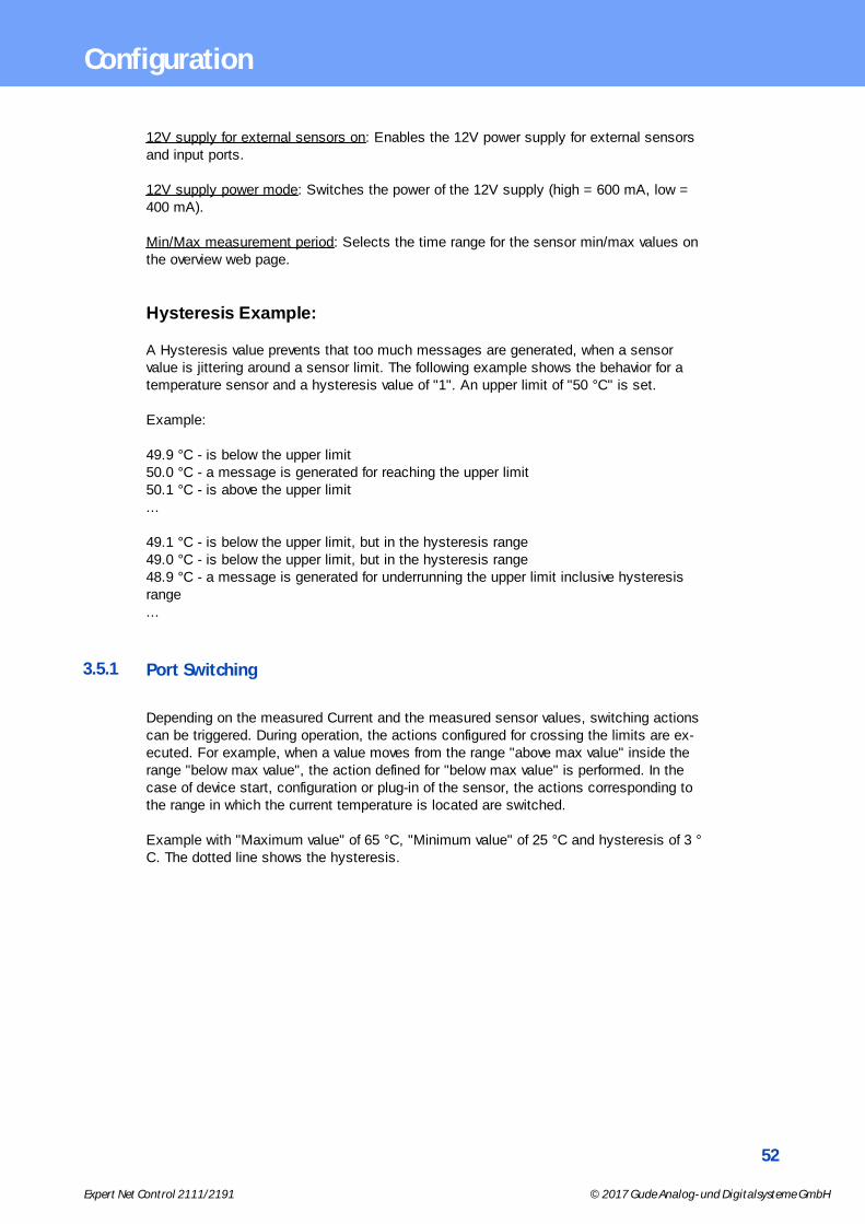
12V supply for external sensors on: Enables the 12V power supply for external sensorsand input ports.
12V supply power mode: Switches the power of the 12V supply (high = 600 mA, low =400 mA).
Min/Max measurement period: Selects the time range for the sensor min/max values onthe overview web page.
Hysteresis Example:
A Hysteresis value prevents that too much messages are generated, when a sensorvalue is jittering around a sensor limit. The following example shows the behavior for atemperature sensor and a hysteresis value of "1". An upper limit of "50 °C" is set.
Example:
49.9 °C - is below the upper limit50.0 °C - a message is generated for reaching the upper limit50.1 °C - is above the upper limit...
49.1 °C - is below the upper limit, but in the hysteresis range49.0 °C - is below the upper limit, but in the hysteresis range48.9 °C - a message is generated for underrunning the upper limit inclusive hysteresisrange...
3.5.1 Port Switching
Depending on the measured Current and the measured sensor values, switching actionscan be triggered. During operation, the actions configured for crossing the limits are ex-ecuted. For example, when a value moves from the range "above max value" inside therange "below max value", the action defined for "below max value" is performed. In thecase of device start, configuration or plug-in of the sensor, the actions corresponding tothe range in which the current temperature is located are switched.
Example with "Maximum value" of 65 °C, "Minimum value" of 25 °C and hysteresis of 3 °C. The dotted line shows the hysteresis.

53
Expert Net Control 2111/2191 © 2017 Gude Analog- und Digitalsysteme GmbH
Configuration
Actions during configuration, device start or plugging in the sensor (for given example):
actual temperatureduring configuration
actions
70 °C Port 1 Off (above max) + Port 2 On (above min)
45 °C Port 1 On (below max) + Port 2 On (above min)
20 °C Port 1 On (below max) + Port 2 Off (below min)
Action matrix during operation when limit values are exceeded (for given example):
to "above max" to "below max" to "above min" to "below min"
from "above max" - P1 On P1 On P1 On + P2 Off
from "below max" P1 Off - - P2 Off
from "above min" P1 Off - - P2 Off
from "below min" P1 Off + P2 On P2 On P2 On -
Only the switching operations for which actions have been defined, are triggered. Ifno "On" or "Off" action is defined for a port, the port can never reach this state by ex-ceeding sensor values. Unless it is the initial state.
54
Expert Net Control 2111/2191 © 2017 Gude Analog- und Digitalsysteme GmbH
Configuration
3.6 E-Mail
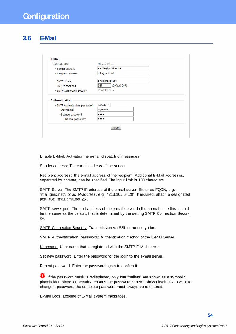
Enable E-Mail: Activates the e-mail dispatch of messages.
Sender address: The e-mail address of the sender.
Recipient address: The e-mail address of the recipient. Additional E-Mail addresses,separated by comma, can be specified. The input limit is 100 characters.
SMTP Server: The SMTP IP-address of the e-mail server. Either as FQDN, e.g:"mail.gmx.net", or as IP-address, e.g: "213.165.64.20". If required, attach a designatedport, e.g: "mail.gmx.net:25".
SMTP server port: The port address of the e-mail server. In the normal case this shouldbe the same as the default, that is determined by the setting SMTP Connection Secur-ity.
SMTP Connection Security: Transmission via SSL or no encryption.
SMTP Authentification (password): Authentication method of the E-Mail Server.
Username: User name that is registered with the SMTP E-Mail server.
Set new password: Enter the password for the login to the e-mail server.
Repeat password: Enter the password again to confirm it.
If the password mask is redisplayed, only four "bullets" are shown as a symbolicplaceholder, since for security reasons the password is never shown itself. If you want tochange a password, the complete password must always be re-entered.
E-Mail Logs: Logging of E-Mail system messages.
55
Expert Net Control 2111/2191 © 2017 Gude Analog- und Digitalsysteme GmbH
Configuration
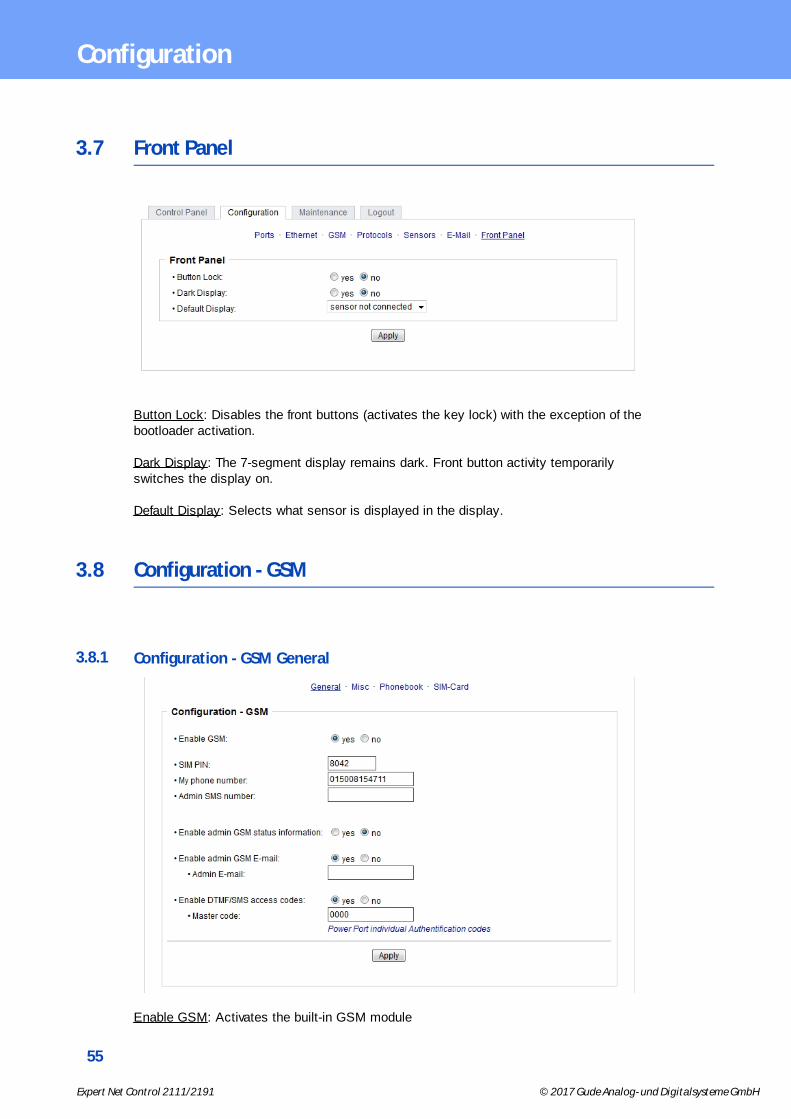
3.7 Front Panel
Button Lock: Disables the front buttons (activates the key lock) with the exception of thebootloader activation.
Dark Display: The 7-segment display remains dark. Front button activity temporarilyswitches the display on.
Default Display: Selects what sensor is displayed in the display.
3.8 Configuration - GSM
3.8.1 Configuration - GSM General
Enable GSM: Activates the built-in GSM module

56
Expert Net Control 2111/2191 © 2017 Gude Analog- und Digitalsysteme GmbH
Configuration
SIM PIN: Switches the PIN request of the SIM card on. A wrong Pin leads to a blockingof the SIM card. You cannot change the PIN of the SIM card via this menu option.
My phone number: Please enter here the phone number of the inserted SIM card
Admin SMS number: All device changes are sent via SMS to this mobile number.
Enable admin GSM status information: When active, all GSM status changes are sentvia SMS to the Admin.
Enable admin GSM E-mail: When active, all GSM status changes are sent via E-Mail tothe Admin. The e-mails are sent via the SMS to email gateway.
Admin E-mail: Email address to which the GSM messages are sent.
Enable DTMF/SMS access codes: When activated, the Mastercode or Portcode isneeded to switch a port.
Master code: Sets the GSM Mastercode.
3.8.2 Configuration - GSM Misc
Enable phonebook check: If selected, only numbers registered to the phonebook can ac-cess the GSM module. All other numbers are ignored.
Enable freecall: When active, without accumulating phone charges, the functions as-signed to a dialed number can be triggered.
Enable GSM for admin only: If enabled, the GSM functions can only be used when activ-ated from the entered GSM Admin number.
Enable SMS response: When activated, every command SMS is acknowledged from ananswer SMS.
57
Expert Net Control 2111/2191 © 2017 Gude Analog- und Digitalsysteme GmbH
Configuration
Enable SMS errors/warning: Enables the sending of an error SMS when a defective com-mand SMS was received.
Enable coverage messages: Sends status messages, when the signal quality is chan-ging.
Enable port name indication: If selected, the complete portname is sent via SMS. E.g.,instead of "Port 1" the name "server 1. floor". This can lead to longer SMS with highercosts.
Enable autosync SMS: When this options is enabled, the EPC tries to request date andtime information from the GSM network after power-up.
Enablevoice in voice call: If enabled, you hear voice samples when a call is coming in(Voicecall).
machine-to-machine DTMF tones: Enables DTMF tones in voice steering.
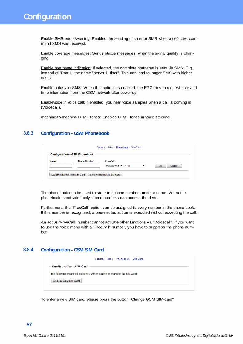
3.8.3 Configuration - GSM Phonebook
The phonebook can be used to store telephone numbers under a name. When thephonebook is activated only stored numbers can access the device.
Furthermore, the "FreeCall" option can be assigned to every number in the phone book.If this number is recognized, a preselected action is executed without accepting the call.
An active "FreeCall" number cannot activate other functions via "Voicecall". If you wantto use the voice menu with a "FreeCall" number, you have to suppress the phone num-ber.
3.8.4 Configuration - GSM SIM Card
To enter a new SIM card, please press the button "Change GSM SIM-card".

58
Expert Net Control 2111/2191 © 2017 Gude Analog- und Digitalsysteme GmbH
Configuration
3.8.5 Configuration - GSM Provider
This menu only appears when you insert a SIM card from a phone company that oper-ates outside of Germany. To receive necessary information, contact your wireless ser-vice provider.
IMSI: Your IMSI number.
The International Mobile Subscriber Identity (IMSI) is used in GSM and UMTS mobilenetworks to uniquely identify network nodes (internal subscriber identity). Among otherdata, the IMSI is stored in a special smart card, the so-called SIM (Subscriber IdentityModule). A worldwide unique IMSI number is awarded every customer of a mobile net-work. While the IMSI has nothing to do with the telephone number that is assigned tothe SIM card.
SMS to Email Gateway: The number of the SMS to email gateway for your network pro-vider.
Balance request code: Please enter the word that names the prepaid balance: e.g. "bal-ance", "conto", "balances".
You will find this word in the news of your provider when you query your prepaid balance.The correct spelling is important to help the device recognizing whether the current bal-ance is communicated in a message.
Balance parsing string: Enter the query that you send to your provider to access yourprepaid balance: E.g. *101#

Specifications
60
Expert Net Control 2111/2191 © 2017 Gude Analog- und Digitalsysteme GmbH
Specifications
4 Specifications
4.1 IP ACL
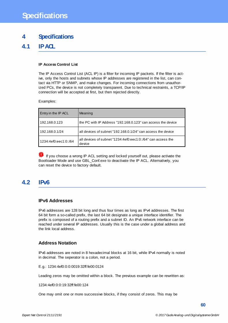
IP Access Control List
The IP Access Control List (ACL IP) is a filter for incoming IP packets. If the filter is act-ive, only the hosts and subnets whose IP addresses are registered in the list, can con-tact via HTTP or SNMP, and make changes. For incoming connections from unauthor-ized PCs, the device is not completely transparent. Due to technical restraints, a TCP/IPconnection will be accepted at first, but then rejected directly.
Examples:
Entry in the IP ACL Meaning
192.168.0.123 the PC with IP Address "192.168.0.123" can access the device
192.168.0.1/24 all devices of subnet "192.168.0.1/24" can access the device
1234:4ef0:eec1:0::/64all devices of subnet "1234:4ef0:eec1:0::/64" can access thedevice
If you choose a wrong IP ACL setting and locked yourself out, please activate theBootloader Mode and use GBL_Conf.exe to deactivate the IP ACL. Alternatively, youcan reset the device to factory default.
4.2 IPv6
IPv6 Addresses
IPv6 addresses are 128 bit long and thus four times as long as IPv4 addresses. The first64 bit form a so-called prefix, the last 64 bit designate a unique interface identifier. Theprefix is composed of a routing prefix and a subnet ID. An IPv6 network interface can bereached under several IP addresses. Usually this is the case under a global address andthe link local address.
Address Notation
IPv6 addresses are noted in 8 hexadecimal blocks at 16 bit, while IPv4 normally is notedin decimal. The seperator is a colon, not a period.
E.g.: 1234:4ef0:0:0:0019:32ff:fe00:0124
Leading zeros may be omitted within a block. The previous example can be rewritten as:
1234:4ef0:0:0:19:32ff:fe00:124
One may omit one or more successive blocks, if they consist of zeros. This may be
61
Expert Net Control 2111/2191 © 2017 Gude Analog- und Digitalsysteme GmbH
Specifications
done only once within an IPv6 address!
1234:4ef0::19:32ff:fe00:124
One may use the usual decimal notation of IPv4 for the last 4 bytes:
1234:4ef0::19:32ff:254.0.1.36
4.3 Radius
The passwords for HTTP, telnet, and serial console (depending on the model) can bestored locally and / or authenticated via RADIUS. The RADIUS configuration supports aprimary server and a backup server. If the primary server does respond, the RADIUS re-quest is sent to the backup server. If the local password and RADIUS are enabled at thesame time, the system is first checking locally, and then in the event of a failure theRADIUS servers are contacted.
RADIUS attributes
The following RADIUS attributes are evaluated by the client:
Session-Timeout: This attribute specifies (in seconds) how long an accepted RADIUSrequest is valid. After this time has elapsed, the RADIUS server must be promptedagain. If this attribute is not returned, the default timeout entry from the configuration isused instead.Filter-Id: If the value "admin" is set for this attribute, then an admin rights are assignedfor the login, otherwise only user access.Service-Type: This is an alternative to Filter-Id. A service type of "6" or "7" means ad-min rights for the HTTP login, otherwise only limited user access.
HTTP Login
The HTTP login takes place via Basic Authentication. This means that it is the respons-ibility of the web server, how long the login credentials are temporarily stored there. TheRADIUS parameter "Session-Timeout" therefore does not determine when the user hasto login again, but at what intervals the RADIUS servers are asked again.
4.4 Automated Access
The device can be accessed automatically via four different interfaces, which offer differ-ent possibilities to access the configuration data and status information. Only http andthe console (telnet and serial) provide full access to the device.
List of different access options (if supported by the model):
Interface Scope of Access
HTTP read / write all configuration data
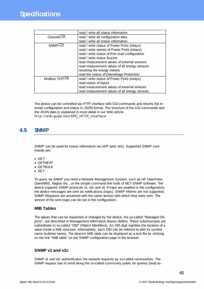
62
Expert Net Control 2111/2191 © 2017 Gude Analog- und Digitalsysteme GmbH
Specifications
read / write all status information
Console read / write all configuration data read / write all status information
SNMP read / write status of Power Ports (relays) read / write names of Power Ports (relays) read / write status of Port start configuration read / write status Buzzer read measurement values of external sensors read measurement values of all energy sensors resetting the energy meters read the status of Overvoltage Protection
Modbus TCP read / write status of Power Ports (relays) read status of Inputs read measurement values of external sensors read measurement values of all energy sensors
The device can be controlled via HTTP interface with CGI commands and returns the in-ternal configuration and status in JSON format. The structure of the CGI commands andthe JSON data is explained in more detail in our Wiki article: http://wiki.gude.info/EPC_HTTP_Interface
4.5 SNMP
SNMP can be used for status information via UDP (port 161). Supported SNMP com-mands are:
· GET· GETNEXT· GETBULK· SET
To query via SNMP you need a Network Management System, such as HP OpenView,OpenNMS, Nagios etc., or the simple command line tools of NET-SNMP software. Thedevice supports SNMP protocols v1, v2c and v3. If traps are enabled in the configuration,the device messages are sent as notifications (traps). SNMP Informs are not supported.SNMP Requests are answered with the same version with which they were sent. Theversion of the sent traps can be set in the configuration.
MIB Tables
The values that can be requested or changed by the device, the so-called "Managed Ob-jects", are described in Management Information Bases (MIBs). These substructures aresubordinate to so-called "OID" (Object Identifiers). An OID digit signifies the location of avalue inside a MIB structure. Alternatively, each OID can be referred to with its symbolname (subtree name). The device's MIB table can be displayed as a text file by clickingon the link "MIB table" on the SNMP configuration page in the browser.
SNMP v1 and v2c
SNMP v1 and v2c authenticates the network requests by so-called communities. TheSNMP request has to send along the so-called community public for queries (read ac-
69
62
84

63
Expert Net Control 2111/2191 © 2017 Gude Analog- und Digitalsysteme GmbH
Specifications
cess) and the community private for status changes (write access) . The SNMPcommunities are read and write passwords. In SNMP v1 and v2 the communities aretransmitted unencrypted on the network and can be easily intercepted with IP snifferswithin this collision domain. To enforce limited access we recommend the use of DMZ orIP-ACL.
SNMP v3
Because the device has no multiuser management, only one user (default name "stand-ard") is detected in SNMP v3. From the User-based Security Model (USM) MIB vari-ables, there is a support of "usmStats ..." counter. The "usmUser ..." variables will beadded with the enhancement of additional users in later firmware versions. The systemhas only one context. The system accepts the context "normal" or an empty context.
Authentication
The algorithms "HMAC-MD5-96" and "HMAC-SHA-96" are available for authentication. Inaddition, the "HMAC-SHA-2" variants (RFC7630) "SHA-256", "SHA-384" and "SHA-512"are implemented.
"SHA-384" and "SHA512" are calculated purely in software. If "SHA-384" or "SHA-
512" is set on the configuration page, the time for the key generation may take once upto approx. 45 seconds.
Encryption
The methods "DES", "3DES", "AES-128", "AES-192" and "AES-256" are supported incombination with "HMAC-MD5-96" and "HMAC-SHA-96." For the "HMAC-SHA-2" proto-cols, there is currently neither RFC nor draft that will allow for cooperation with an en-cryption.
While in the settings "AES-192" and "AES256" the key calculation is based on"draft-blumenthalphoto-aes-usm-04", the methods "AES 192-3DESKey" and "AES 256-3DESKey" utilize a key generation, which is also used in the "3DES" configuration("draft-reeder-snmpv3-usm-3desede-00"). If one is not an SNMP expert, it is recommen-ded to try in each case the settings with and without "...- 3DESKey".
Passwords
The passwords for authentication and encryption are stored only as computed hashesfor security reasons. Thus it is, if at all, very difficult to infer the initial password.However, the hash calculation changes with the set algorithms. If the authentication orprivacy algorithms are changed, the passwords must be re-entered in the configurationdialog.
Security
The following aspects should be considered:
· If encryption or authentication is used, then SNMP v1 and v2c should be turned off.Otherwise the device could be accessed with it.
· If only authentication is used, then the new "HMAC-SHA-2" methods are superior tothe MD5 or SHA-1 hashing algorithms. Since only SHA-256 is accelerated in hard-ware, and SHA-384 and SHA-512 are calculated purely in software, one should nor-mally select SHA-256. From a cryptographic point of view, the security of SHA-256 is

64
Expert Net Control 2111/2191 © 2017 Gude Analog- und Digitalsysteme GmbH
Specifications
sufficient for today's usage.· For SHA-1, there are a little less attack scenarios than MD5. If in doubt, SHA-1 is
preferable.· Encryption "DES" is considered very unsafe, use only in an emergency for reasons of
compatibility!· For cryptologists it's a debatable point whether "HMAC-MD5-96" and "HMAC-SHA-96"
can muster enough entropy for key lengths of "AES-192" or "AES-256".· From the foregoing considerations, we would recommended at present "HMAC-SHA-
96" with "AES-128" as authentication and encryption method.
NET-SNMP
NET-SNMP provides a very widespread collection of SNMP command-line tools (snmp-get, snmpset, snmpwalk etc.) NET-SNMP is among others available for Linux and Win-dows. After installing NET-SNMP you should create the device-specific MIB of the devicein NET-SMP share directory, e.g. after
c:\usr\share\snmp\mibs
or
/usr/share/snmp/mibs
So later you can use the 'subtree names' instead of OIDs:
Name: snmpwalk -v2c -mALL -c public 192.168.1.232 gudeads
OID: snmpwalk -v2c -mALL -c public 192.168.1.232 1.3.6.1.4.1.28507
NET-SNMP Examples
Query Power Port 1 switching state:
snmpget -v2c -mALL -c public 192.168.1.232 epc822XPortState.1
Switch on Power Port 1:
snmpset -v2c -mALL -c private 192.168.1.232 epc822XPortState.1 integer 1
4.5.1 Device MIB 2111
Below is a table of all device-specific OID 's which can be accessed via SNMP. In thenumerical representation of the OID the prefix " 1.3.6.1.4.1.28507 " (Gude EnterpriseOID) was omitted at each entry in the table to preserve space. The example for a com-plete OID would be "1.3.6.1.4.1.28507.60.1.1.1.1". A distinction is made in SNMP OID 'sin between tables and scalars. OID scalar have the extension ".0" and only specify avalue. In SNMP tables the "x" is replaced by an index (1 or greater) to address a valuefrom the table.
Name OID Type Acc.Description
enc2111TrapCtrl .60.1.1.1.1.0 Integer32 RW
0 = off 1 = Ver. 1 2 = Ver. 2c 3 = Ver. 3
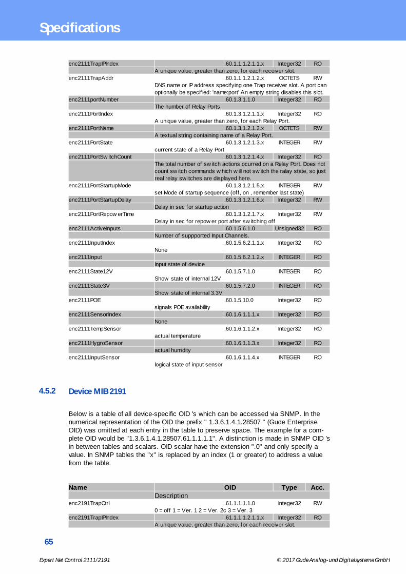
65
Expert Net Control 2111/2191 © 2017 Gude Analog- und Digitalsysteme GmbH
Specifications
enc2111TrapIPIndex .60.1.1.1.2.1.1.x Integer32 RO
A unique value, greater than zero, for each receiver slot.
enc2111TrapAddr .60.1.1.1.2.1.2.x OCTETS RW
DNS name or IP address specifying one Trap receiver slot. A port can
optionally be specif ied: 'name:port' An empty string disables this slot.
enc2111portNumber .60.1.3.1.1.0 Integer32 RO
The number of Relay Ports
enc2111PortIndex .60.1.3.1.2.1.1.x Integer32 RO
A unique value, greater than zero, for each Relay Port.
enc2111PortName .60.1.3.1.2.1.2.x OCTETS RW
A textual string containing name of a Relay Port.
enc2111PortState .60.1.3.1.2.1.3.x INTEGER RW
current state of a Relay Port
enc2111PortSw itchCount .60.1.3.1.2.1.4.x Integer32 RO
The total number of sw itch actions ocurred on a Relay Port. Does not
count sw itch commands w hich w ill not sw itch the ralay state, so just
real relay sw itches are displayed here.
enc2111PortStartupMode .60.1.3.1.2.1.5.x INTEGER RW
set Mode of startup sequence (off, on , remember last state)
enc2111PortStartupDelay .60.1.3.1.2.1.6.x Integer32 RW
Delay in sec for startup action
enc2111PortRepow erTime .60.1.3.1.2.1.7.x Integer32 RW
Delay in sec for repow er port after sw itching off
enc2111ActiveInputs .60.1.5.6.1.0 Unsigned32 RO
Number of suppported Input Channels.
enc2111InputIndex .60.1.5.6.2.1.1.x Integer32 RO
None
enc2111Input .60.1.5.6.2.1.2.x INTEGER RO
Input state of device
enc2111State12V .60.1.5.7.1.0 INTEGER RO
Show state of internal 12V
enc2111State3V .60.1.5.7.2.0 INTEGER RO
Show state of internal 3.3V
enc2111POE .60.1.5.10.0 Integer32 RO
signals POE availability
enc2111SensorIndex .60.1.6.1.1.1.x Integer32 RO
None
enc2111TempSensor .60.1.6.1.1.2.x Integer32 RO
actual temperature
enc2111HygroSensor .60.1.6.1.1.3.x Integer32 RO
actual humidity
enc2111InputSensor .60.1.6.1.1.4.x INTEGER RO
logical state of input sensor
4.5.2 Device MIB 2191
Below is a table of all device-specific OID 's which can be accessed via SNMP. In thenumerical representation of the OID the prefix " 1.3.6.1.4.1.28507 " (Gude EnterpriseOID) was omitted at each entry in the table to preserve space. The example for a com-plete OID would be "1.3.6.1.4.1.28507.61.1.1.1.1". A distinction is made in SNMP OID 'sin between tables and scalars. OID scalar have the extension ".0" and only specify avalue. In SNMP tables the "x" is replaced by an index (1 or greater) to address a valuefrom the table.
Name OID Type Acc.Description
enc2191TrapCtrl .61.1.1.1.1.0 Integer32 RW
0 = off 1 = Ver. 1 2 = Ver. 2c 3 = Ver. 3
enc2191TrapIPIndex .61.1.1.1.2.1.1.x Integer32 RO
A unique value, greater than zero, for each receiver slot.

66
Expert Net Control 2111/2191 © 2017 Gude Analog- und Digitalsysteme GmbH
Specifications
enc2191TrapAddr .61.1.1.1.2.1.2.x OCTETS RW
DNS name or IP address specifying one Trap receiver slot. A port can
optionally be specif ied: 'name:port' An empty string disables this slot.
enc2191portNumber .61.1.3.1.1.0 Integer32 RO
The number of Relay Ports
enc2191PortIndex .61.1.3.1.2.1.1.x Integer32 RO
A unique value, greater than zero, for each Relay Port.
enc2191PortName .61.1.3.1.2.1.2.x OCTETS RW
A textual string containing name of a Relay Port.
enc2191PortState .61.1.3.1.2.1.3.x INTEGER RW
current state of a Relay Port
enc2191PortSw itchCount .61.1.3.1.2.1.4.x Integer32 RO
The total number of sw itch actions ocurred on a Relay Port. Does not
count sw itch commands w hich w ill not sw itch the ralay state, so just
real relay sw itches are displayed here.
enc2191PortStartupMode .61.1.3.1.2.1.5.x INTEGER RW
set Mode of startup sequence (off, on , remember last state)
enc2191PortStartupDelay .61.1.3.1.2.1.6.x Integer32 RW
Delay in sec for startup action
enc2191PortRepow erTime .61.1.3.1.2.1.7.x Integer32 RW
Delay in sec for repow er port after sw itching off
enc2191ActiveInputs .61.1.5.6.1.0 Unsigned32 RO
Number of suppported Input Channels.
enc2191InputIndex .61.1.5.6.2.1.1.x Integer32 RO
None
enc2191Input .61.1.5.6.2.1.2.x INTEGER RO
Input state of device
enc2191State12V .61.1.5.7.1.0 INTEGER RO
Show state of internal 12V
enc2191State3V .61.1.5.7.2.0 INTEGER RO
Show state of internal 3.3V
enc2191POE .61.1.5.10.0 Integer32 RO
signals POE availability
enc2191SensorIndex .61.1.6.1.1.1.x Integer32 RO
None
enc2191TempSensor .61.1.6.1.1.2.x Integer32 RO
actual temperature
enc2191HygroSensor .61.1.6.1.1.3.x Integer32 RO
actual humidity
enc2191InputSensor .61.1.6.1.1.4.x INTEGER RO
logical state of input sensor
4.6 SSL
TLS Standard
The device is compatible with the standards TLSv1.0 to TLSv1.2. Due to lack of security,SSLv3.0 as well as RC4 and DES encryptions are deactivated.
The following TLS Ciphersuites are supported:
· TLS_RSA_WITH_3DES_EDE_CBC_SHA· TLS_DHE_RSA_WITH_3DES_EDE_CBC_SHA· TLS_RSA_WITH_AES_128_CBC_SHA· TLS_DHE_RSA_WITH_AES_128_CBC_SHA· TLS_RSA_WITH_AES_256_CBC_SHA· TLS_DHE_RSA_WITH_AES_256_CBC_SHA· TLS_RSA_WITH_AES_128_CBC_SHA256· TLS_RSA_WITH_AES_256_CBC_SHA256

67
Expert Net Control 2111/2191 © 2017 Gude Analog- und Digitalsysteme GmbH
Specifications
· TLS_DHE_RSA_WITH_AES_128_CBC_SHA256· TLS_DHE_RSA_WITH_AES_256_CBC_SHA256· TLS_RSA_WITH_AES_128_GCM_SHA256· TLS_DHE_RSA_WITH_AES_128_GCM_SHA256· TLS_PSK_WITH_AES_128_GCM_SHA256· TLS_PSK_WITH_AES_128_CBC_SHA256· TLS_ECDH_ECDSA_WITH_3DES_EDE_CBC_SHA· TLS_ECDH_ECDSA_WITH_AES_128_CBC_SHA· TLS_ECDH_ECDSA_WITH_AES_256_CBC_SHA· TLS_ECDHE_ECDSA_WITH_3DES_EDE_CBC_SHA· TLS_ECDHE_ECDSA_WITH_AES_128_CBC_SHA· TLS_ECDHE_ECDSA_WITH_AES_256_CBC_SHA· TLS_ECDH_RSA_WITH_3DES_EDE_CBC_SHA· TLS_ECDH_RSA_WITH_AES_128_CBC_SHA· TLS_ECDH_RSA_WITH_AES_256_CBC_SHA· TLS_ECDHE_RSA_WITH_3DES_EDE_CBC_SHA· TLS_ECDHE_RSA_WITH_AES_128_CBC_SHA· TLS_ECDHE_RSA_WITH_AES_256_CBC_SHA· TLS_ECDHE_ECDSA_WITH_AES_128_CBC_SHA256· TLS_ECDH_ECDSA_WITH_AES_128_CBC_SHA256· TLS_ECDHE_RSA_WITH_AES_128_CBC_SHA256· TLS_ECDH_RSA_WITH_AES_128_CBC_SHA256· TLS_ECDHE_ECDSA_WITH_AES_128_GCM_SHA256· TLS_ECDH_ECDSA_WITH_AES_128_GCM_SHA256· TLS_ECDHE_RSA_WITH_AES_128_GCM_SHA256· TLS_ECDH_RSA_WITH_AES_128_GCM_SHA256· TLS_RSA_WITH_AES_128_CCM· TLS_RSA_WITH_AES_256_CCM· TLS_DHE_RSA_WITH_AES_128_CCM· TLS_DHE_RSA_WITH_AES_256_CCM· TLS_RSA_WITH_AES_128_CCM_8· TLS_RSA_WITH_AES_256_CCM_8· TLS_DHE_RSA_WITH_AES_128_CCM_8· TLS_DHE_RSA_WITH_AES_256_CCM_8· TLS_ECDHE_RSA_WITH_CHACHA20_POLY1305_SHA256· TLS_ECDHE_ECDSA_WITH_CHACHA20_POLY1305_SHA256· TLS_DHE_RSA_WITH_CHACHA20_POLY1305_SHA256
Creating your own Certificates
The SSL stack is supplied with a specially newly generated certificate. There is no function togenerate the local certificate anew at the touch of a button, since the required random num-bers in an embedded device are usually not independent enough. However, you can createnew certificates and import them to the device. The server accepts RSA (1024/2048/4096) andECC (Elliptic Curve Cryptography) certificates.
Usually OpenSSL is used to create an SSL certificate. For Windows for example, there is thelight version of Shinning Light Productions. There you open a command prompt, change tothe directory "C:\OpenSSL-Win32\bin" and set these environment variables:
set openssl_conf=C:\OpenSSL-Win32\bin\openssl.cfgset RANDFILE=C:\OpenSSL-Win32\bin\.rnd
Here are some examples for the generation with OpenSSL:
Creation of a self-signed RSA 2048-bit certificate
openssl genrsa -out server.key 2048
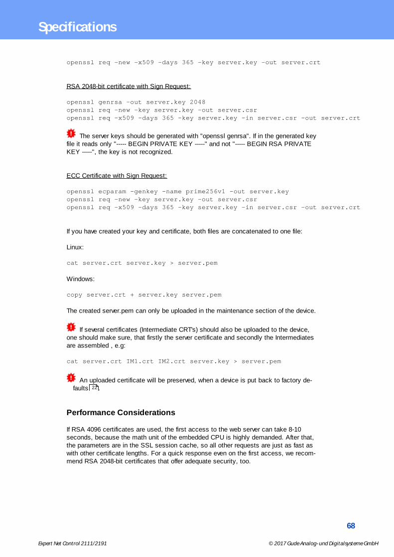
68
Expert Net Control 2111/2191 © 2017 Gude Analog- und Digitalsysteme GmbH
Specifications
openssl req -new -x509 -days 365 -key server.key -out server.crt
RSA 2048-bit certificate with Sign Request:
openssl genrsa -out server.key 2048 openssl req -new -key server.key -out server.csropenssl req -x509 -days 365 -key server.key -in server.csr -out server.crt
The server keys should be generated with "openssl genrsa". If in the generated keyfile it reads only "----- BEGIN PRIVATE KEY -----" and not "----- BEGIN RSA PRIVATEKEY -----", the key is not recognized.
ECC Certificate with Sign Request:
openssl ecparam -genkey -name prime256v1 -out server.keyopenssl req -new -key server.key -out server.csropenssl req -x509 -days 365 -key server.key -in server.csr -out server.crt
If you have created your key and certificate, both files are concatenated to one file:
Linux:
cat server.crt server.key > server.pem
Windows:
copy server.crt + server.key server.pem
The created server.pem can only be uploaded in the maintenance section of the device.
If several certificates (Intermediate CRT's) should also be uploaded to the device,one should make sure, that firstly the server certificate and secondly the Intermediatesare assembled , e.g:
cat server.crt IM1.crt IM2.crt server.key > server.pem
An uploaded certificate will be preserved, when a device is put back to factory de-faults .
Performance Considerations
If RSA 4096 certificates are used, the first access to the web server can take 8-10seconds, because the math unit of the embedded CPU is highly demanded. After that,the parameters are in the SSL session cache, so all other requests are just as fast aswith other certificate lengths. For a quick response even on the first access, we recom-mend RSA 2048-bit certificates that offer adequate security, too.
22

69
Expert Net Control 2111/2191 © 2017 Gude Analog- und Digitalsysteme GmbH
Specifications
4.7 Console
For the configuration and control of the device, there is a set of commands with paramet-ers that can be entered through a console. The console is available via Telnet, or fordevices with RS232 port through using a serial terminal. The communication can also beperformed automated (e.g. via scripting languages). The console features are configuredthrough the web interface .
Command Set
There are several command levels. The following commands are usable from each level:
back go back one level
help all commands of the actual level
help all show all commands
logout logout (only when login required)
quit quit console
The "help" command returns all the commands of the current level. If "help" is calledfrom the top level, e.g. the line "http [subtopics]" appears. This means that there is an-other level for "http". With the command "http help" all commands below "http" areshown. Alternatively, with entering "http" you can select the http level, and "help" showsall the commands on the selected level. The command "back" again selects the toplevel. It is possible to use "help" at any position: "http passwd help" provides all com-mands that have the prefix "http passwd".
You will find a complete list of all possible device commands in the chapter "Cmd Over-view".
Parameter
If parameters are expected for the command, the parameter may be passed as numericor constant. If e.g. you get the following line as help:
http server set {http_both=0|https_only=1|http_only=2}
the following instruction pairs are equivalent:
http server set https_onlyhttp server set 1
or
http server set https_bothhttp server set 0
Numerical parameters can be entered with different bases. Here is an example of thedecimal value 11:
Base Input
45

70
Expert Net Control 2111/2191 © 2017 Gude Analog- und Digitalsysteme GmbH
Specifications
decimal (10) 11
hexadecimal (16) 0xb
octal (8) 013
binary (2) 0b1011
Return Values
If a command is unknown or a parameter is incorrect, the output "ERR." is given at thebeginning of the line, followed by a description of the fault. Successful instructionswithout special return value will be acknowledged by "OK.". All other return values areoutput within a single line. There are of two exceptions:
1. Some configuration changes, that affect TCP / IP and UDP, need a restart to be ap-plied. These parameters are output on two lines. In the first line the current value isshown, on the second row the value after a restart. In the "Cmd Overview" table thisis marked with "Note 2".
2. Other configurations (such as the assigned IPv6 addresses) have several values thatcan change dynamically. This is marked with "Note 3" in the "Cmd Overview" table.
Numerical Returns
For parameters that support constants, these constants are output as return values. Tobetter deal with scripting languages, it may be easier to work only with numerical re-turns. The command "vt100 numeric set ON" enables that only numerical values
appear.
Comments
If you use a tool to send an entire file of commands via Telnet, it is helpful, if you canplace comments in there. Beginning with the comment character "#", the remaining con-tents of a line is ignored.
Telnet
If the configuration "Raw Mode" is turned off, it is tried to negotiate the Telnet configura-tion between client and server using IAC commands. If this fails, the editing functions arenot active, and the "Activate echo" option determines whether the characters sent to theTelnet server will be returned. Normally the client begins with the IAC negotiation. If thisis not the case with the client, the device configuration "Active negotiation" should beturned on.
Raw Mode
If you want to use the console only automated, it may be advantageous to set the con-figuration "Raw mode" to "yes" and "Activate echo" to "no" to. Then there is no interfer-ing interaction with the editor functions and the is no need to filter the sent characters toprocess the return values.
If in the console "Raw mode" is activated but not in the used Telnet client, the IACcommands sent at the beginning can appear as interfering characters in the command
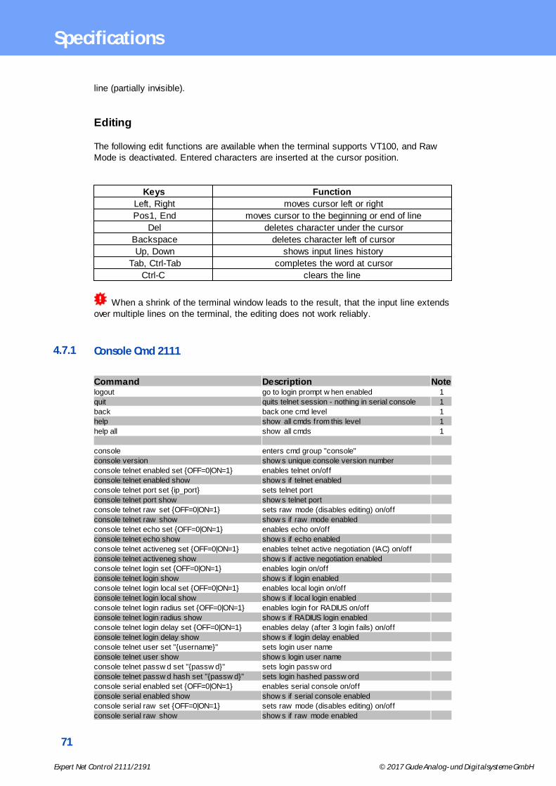
71
Expert Net Control 2111/2191 © 2017 Gude Analog- und Digitalsysteme GmbH
Specifications
line (partially invisible).
Editing
The following edit functions are available when the terminal supports VT100, and RawMode is deactivated. Entered characters are inserted at the cursor position.
Keys Function
Left, Right moves cursor left or right
Pos1, End moves cursor to the beginning or end of line
Del deletes character under the cursor
Backspace deletes character left of cursor
Up, Down shows input lines history
Tab, Ctrl-Tab completes the word at cursor
Ctrl-C clears the line
When a shrink of the terminal window leads to the result, that the input line extendsover multiple lines on the terminal, the editing does not work reliably.
4.7.1 Console Cmd 2111
Command Description Notelogout go to login prompt w hen enabled 1
quit quits telnet session - nothing in serial console 1
back back one cmd level 1
help show all cmds from this level 1
help all show all cmds 1
console enters cmd group "console"
console version show s unique console version number
console telnet enabled set {OFF=0|ON=1} enables telnet on/off
console telnet enabled show show s if telnet enabled
console telnet port set {ip_port} sets telnet port
console telnet port show show s telnet port
console telnet raw set {OFF=0|ON=1} sets raw mode (disables editing) on/off
console telnet raw show show s if raw mode enabled
console telnet echo set {OFF=0|ON=1} enables echo on/off
console telnet echo show show s if echo enabled
console telnet activeneg set {OFF=0|ON=1} enables telnet active negotiation (IAC) on/off
console telnet activeneg show show s if active negotiation enabled
console telnet login set {OFF=0|ON=1} enables login on/off
console telnet login show show s if login enabled
console telnet login local set {OFF=0|ON=1} enables local login on/off
console telnet login local show show s if local login enabled
console telnet login radius set {OFF=0|ON=1} enables login for RADIUS on/off
console telnet login radius show show s if RADIUS login enabled
console telnet login delay set {OFF=0|ON=1} enables delay (after 3 login fails) on/off
console telnet login delay show show s if login delay enabled
console telnet user set "{username}" sets login user name
console telnet user show show s login user name
console telnet passw d set "{passw d}" sets login passw ord
console telnet passw d hash set "{passw d}" sets login hashed passw ord
console serial enabled set {OFF=0|ON=1} enables serial console on/off
console serial enabled show show s if serial console enabled
console serial raw set {OFF=0|ON=1} sets raw mode (disables editing) on/off
console serial raw show show s if raw mode enabled
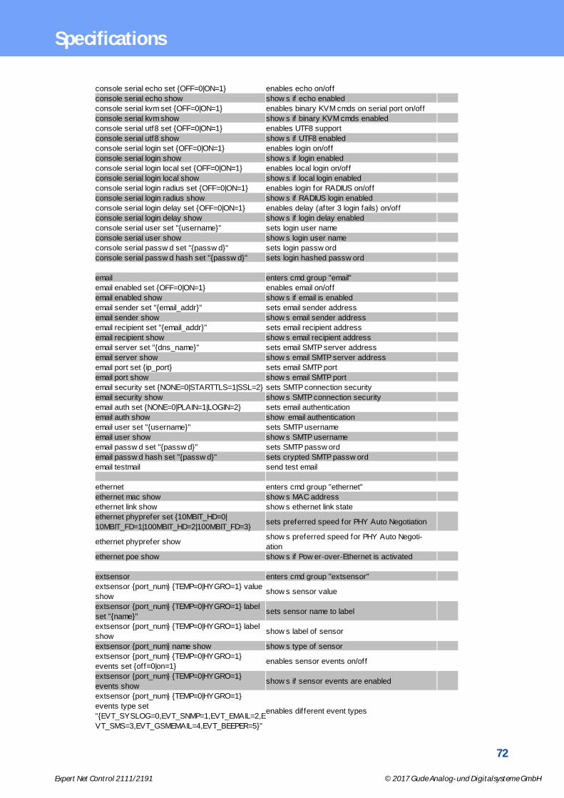
72
Expert Net Control 2111/2191 © 2017 Gude Analog- und Digitalsysteme GmbH
Specifications
console serial echo set {OFF=0|ON=1} enables echo on/off
console serial echo show show s if echo enabled
console serial kvm set {OFF=0|ON=1} enables binary KVM cmds on serial port on/off
console serial kvm show show s if binary KVM cmds enabled
console serial utf8 set {OFF=0|ON=1} enables UTF8 support
console serial utf8 show show s if UTF8 enabled
console serial login set {OFF=0|ON=1} enables login on/off
console serial login show show s if login enabled
console serial login local set {OFF=0|ON=1} enables local login on/off
console serial login local show show s if local login enabled
console serial login radius set {OFF=0|ON=1} enables login for RADIUS on/off
console serial login radius show show s if RADIUS login enabled
console serial login delay set {OFF=0|ON=1} enables delay (after 3 login fails) on/off
console serial login delay show show s if login delay enabled
console serial user set "{username}" sets login user name
console serial user show show s login user name
console serial passw d set "{passw d}" sets login passw ord
console serial passw d hash set "{passw d}" sets login hashed passw ord
email enters cmd group "email"
email enabled set {OFF=0|ON=1} enables email on/off
email enabled show show s if email is enabled
email sender set "{email_addr}" sets email sender address
email sender show show s email sender address
email recipient set "{email_addr}" sets email recipient address
email recipient show show s email recipient address
email server set "{dns_name}" sets email SMTP server address
email server show show s email SMTP server address
email port set {ip_port} sets email SMTP port
email port show show s email SMTP port
email security set {NONE=0|STARTTLS=1|SSL=2} sets SMTP connection security
email security show show s SMTP connection security
email auth set {NONE=0|PLAIN=1|LOGIN=2} sets email authentication
email auth show show email authentication
email user set "{username}" sets SMTP username
email user show show s SMTP username
email passw d set "{passw d}" sets SMTP passw ord
email passw d hash set "{passw d}" sets crypted SMTP passw ord
email testmail send test email
ethernet enters cmd group "ethernet"
ethernet mac show show s MAC address
ethernet link show show s ethernet link state
ethernet phyprefer set {10MBIT_HD=0|
10MBIT_FD=1|100MBIT_HD=2|100MBIT_FD=3}sets preferred speed for PHY Auto Negotiation
ethernet phyprefer showshow s preferred speed for PHY Auto Negoti-
ation
ethernet poe show show s if Pow er-over-Ethernet is activated
extsensor enters cmd group "extsensor"
extsensor {port_num} {TEMP=0|HYGRO=1} value
showshow s sensor value
extsensor {port_num} {TEMP=0|HYGRO=1} label
set "{name}"sets sensor name to label
extsensor {port_num} {TEMP=0|HYGRO=1} label
showshow s label of sensor
extsensor {port_num} name show show s type of sensor
extsensor {port_num} {TEMP=0|HYGRO=1}
events set {off=0|on=1}enables sensor events on/off
extsensor {port_num} {TEMP=0|HYGRO=1}
events showshow s if sensor events are enabled
extsensor {port_num} {TEMP=0|HYGRO=1}
events type set
"{EVT_SYSLOG=0,EVT_SNMP=1,EVT_EMAIL=2,E
VT_SMS=3,EVT_GSMEMAIL=4,EVT_BEEPER=5}"
enables different event types

73
Expert Net Control 2111/2191 © 2017 Gude Analog- und Digitalsysteme GmbH
Specifications
extsensor {port_num} {TEMP=0|HYGRO=1}
events type showshow s w hat event types are enabled
extsensor {port_num} {TEMP=0|HYGRO=1}
maxval set {num}sets maximum value for sensor
extsensor {port_num} {TEMP=0|HYGRO=1}
maxval showshow s maximum value for sensor
extsensor {port_num} {TEMP=0|HYGRO=1} minval
set {num}sets minimum value for sensor
extsensor {port_num} {TEMP=0|HYGRO=1} minval
showshow s minimum value for sensor
extsensor {port_num} {TEMP=0|HYGRO=1} hyst
set {num}sets hysterese value for sensor
extsensor {port_num} {TEMP=0|HYGRO=1} hyst
showshow s hysterese value for sensor
extsensor {port_num} {TEMP=0|HYGRO=1}
{BELOWMIN=0|ABOVEMIN=1|ABOVEMAX=2|
BELOWMAX=3} port set {port_num}
sets Port for Pow er Port Sw itching actions
extsensor {port_num} {TEMP=0|HYGRO=1}
{BELOWMIN=0|ABOVEMIN=1|ABOVEMAX=2|
BELOWMAX=3} port show
show s Port for Pow er Port Sw itching actions
extsensor {port_num} {TEMP=0|HYGRO=1}
{BELOWMIN=0|ABOVEMIN=1|ABOVEMAX=2|
BELOWMAX=3} state set {OFF=0|ON=1|
DISABLED=2}
sets Port state for Pow er Port Sw itching actions
extsensor {port_num} {TEMP=0|HYGRO=1}
{BELOWMIN=0|ABOVEMIN=1|ABOVEMAX=2|
BELOWMAX=3} state show
show s Port state for Pow er Port Sw itching ac-
tions
extsensor period set {24H=0|12H=1|2H=2|1H=3|
30MIN=4}sets sensor Min/Max measurement period
extsensor period show show s sensor Min/Max measurement period
extsensor display set {CURRENT=0|TEMP1=1|
HYGRO1=2|TEMP2=3|HYGRO2=4}sets default display
extsensor display show show s state of default display
http enters cmd group "http"
http server set {HTTP_BOTH=0|HTTPS_ONLY=1|
HTTP_ONLY=2}sets connection types the w ebserver accepts
http server show show s w ebserver accepting connection types
http port set {ip_port} sets http port
http port show show s http port
http portssl set {ip_port} sets https port
http portssl show show s https port
http ajax enabled set {OFF=0|ON=1} enables ajax autorefresh on/off
http ajax enabled show show s if ajax autorefresh enabled
http passw d enabled set {OFF=0|ON=1} enables http passw ord on/off
http passw d enabled show show s if http passw ord enabled
http passw d user set "{passw d}" sets http user passw ord
http passw d admin set "{passw d}" sets http admin passw ord
http passw d hash user set "{passw d}" sets hashed http user passw ord
http passw d hash admin set "{passw d}" sets hashed http admin passw ord
input enters cmd group "input"
input {port_num} state show show s input state
input all state show show s input state of all ports
input {port_num} name set "{name}" sets sensor name to label
input {port_num} name show show s label of sensor
input {port_num} invert enabled set {off=0|on=1} inverts input on/off
input {port_num} invert enabled show show s if input inverted
input {port_num} label {LOW=0|HIGH=1} set
"{name}"sets input low /high text
input {port_num} label {LOW=0|HIGH=1} show show s inputs low /high text
input {port_num} events set {off=0|on=1} enables input events on/off
input {port_num} events show show s if input events are enabled
input {port_num} events type set
"{EVT_SYSLOG=0,EVT_SNMP=1,EVT_EMAIL=2,E
VT_SMS=3,EVT_GSMEMAIL=4,EVT_BEEPER=5}"
enables different event types

74
Expert Net Control 2111/2191 © 2017 Gude Analog- und Digitalsysteme GmbH
Specifications
input {port_num} events type show show s w hat event types are enabled
input {port_num} {LOW=0|HIGH=1} port set
{port_num}sets Port for Pow er Port Sw itching actions
input {port_num} {LOW=0|HIGH=1} port show show s Port for Pow er Port Sw itching actions
input {port_num} {LOW=0|HIGH=1} state set
{OFF=0|ON=1|DISABLED=2}sets Port state for Pow er Port Sw itching actions
input {port_num} {LOW=0|HIGH=1} state showshow s Port state for Pow er Port Sw itching ac-
tions
input volt3 state show show s state of 3V input voltage {ON=1|VERR=3}
input volt12 state set {OFF=0|VLO=1|VHI=2} sets state of 12V input voltage
input volt12 state showshow s state of 12V input voltage {OFF=0|VLO=1|
VHI=2|VERR=3} incl possible error condition
ip4 enters cmd group "ip4"
ip4 hostname set "{name}" sets device hostname
ip4 hostname show show s device hostname 2
ip4 address set "{ip_address}" sets IPv4 address
ip4 address show show s IPv4 address 2
ip4 netmask set "{ip_address}" sets IPv4 netmask
ip4 netmask show show s IPv4 netmask 2
ip4 gatew ay set "{ip_address}" sets IPv4 gatew ay address
ip4 gatew ay show show s IPv4 gatew ay address 2
ip4 dns set "{ip_address}" sets IPv4 DNS server address
ip4 dns show show s IPv4 DNS server address 2
ip4 dhcp enabled set {OFF=0|ON=1} enables IPv4 DHCP on/off
ip4 dhcp enabled show show s IPv4 DHCP state 2
ip6 enters cmd group "ip6"
ip6 enabled set {OFF=0|ON=1} enables IPv6 on/off
ip6 enabled show show s if IPv6 is enabled 2
ip6 routadv enabled set {OFF=0|ON=1} enables IPv6 router advertisement
ip6 routadv enabled show show s IPv6 router advertisement state 2
ip6 dhcp enabled set {OFF=0|ON=1} enables IPv6 DHCP on/off
ip6 dhcp enabled show show s if IPv6 DHCP is enabled 2
ip6 address show show all IPv6 addresses 3
ip6 gatew ay show show all IPv6 gatew ays 3
ip6 dns show show all IPv6 DNS server 3
ip6 manual enabled set {OFF=0|ON=1} enables manual IPv6 addresses
ip6 manual enabled show show s if manual IPv6 addresses are enabled 2
ip6 manual address {1..4} set "{ip_address}" sets manual IPv6 address
ip6 manual address {1..4} show show s manual IPv6 address 2
ip6 manual gatew ay set "{ip_address}" sets manual IPv6 gatew ay address
ip6 manual gatew ay show show s manual IPv6 gatew ay address 2
ip6 manual dns {1..2} set "{ip_address}" sets manual IPv6 DNS server address
ip6 manual dns {1..2} show show s manual IPv6 DNS server address 2
ipacl enters cmd group "ipacl"
ipacl ping enabled set {OFF=0|ON=1} enables ICMP ping on/off
ipacl ping enabled show show s if ICMP ping enabled
ipacl enabled set {OFF=0|ON=1} enable IP f ilter on/off
ipacl enabled show show s if IP f ilter enabled
ipacl f ilter {ipacl_num} set "{dns_name}" sets IP f ilter {ipacl_num}
ipacl f ilter {ipacl_num} show show s IP f ilter {ipacl_num}
modbus enters cmd group "modbus"
modbus enabled set <off=0/on=1> enables Modbus TCP support
modbus enabled show show s if Modbus is enabled
modbus port set <ip_port> sets Modbus TCP port
modbus port show show s Modbus TCP port
port enters cmd group "port"
port {port_num} state set {OFF=0|ON=1} sets port to new state
port {port_num} state show show s port state
port all state set "{port_list}" {OFF=0|ON=1}sets several ports in one cmd - e.g. port all state
set "1,3,5" 1
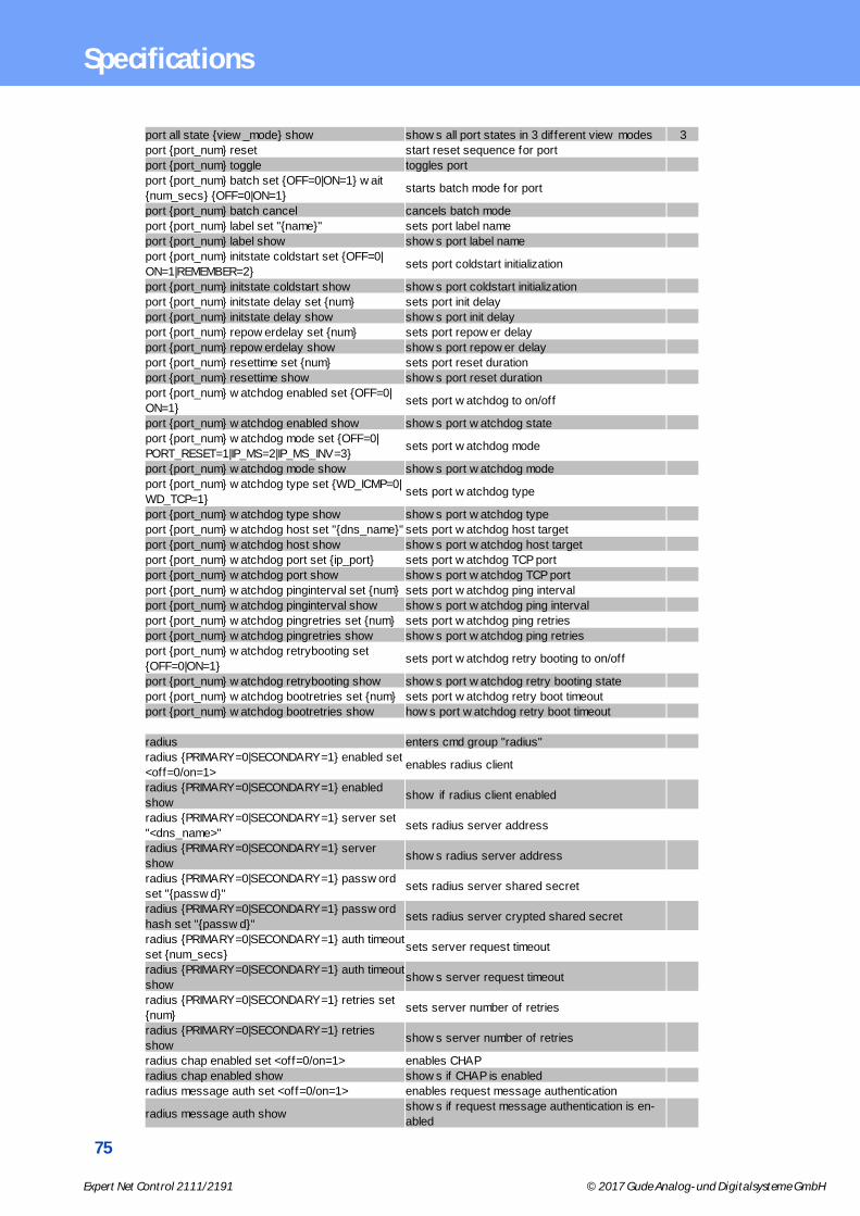
75
Expert Net Control 2111/2191 © 2017 Gude Analog- und Digitalsysteme GmbH
Specifications
port all state {view _mode} show show s all port states in 3 different view modes 3
port {port_num} reset start reset sequence for port
port {port_num} toggle toggles port
port {port_num} batch set {OFF=0|ON=1} w ait
{num_secs} {OFF=0|ON=1}starts batch mode for port
port {port_num} batch cancel cancels batch mode
port {port_num} label set "{name}" sets port label name
port {port_num} label show show s port label name
port {port_num} initstate coldstart set {OFF=0|
ON=1|REMEMBER=2}sets port coldstart initialization
port {port_num} initstate coldstart show show s port coldstart initialization
port {port_num} initstate delay set {num} sets port init delay
port {port_num} initstate delay show show s port init delay
port {port_num} repow erdelay set {num} sets port repow er delay
port {port_num} repow erdelay show show s port repow er delay
port {port_num} resettime set {num} sets port reset duration
port {port_num} resettime show show s port reset duration
port {port_num} w atchdog enabled set {OFF=0|
ON=1}sets port w atchdog to on/off
port {port_num} w atchdog enabled show show s port w atchdog state
port {port_num} w atchdog mode set {OFF=0|
PORT_RESET=1|IP_MS=2|IP_MS_INV=3}sets port w atchdog mode
port {port_num} w atchdog mode show show s port w atchdog mode
port {port_num} w atchdog type set {WD_ICMP=0|
WD_TCP=1}sets port w atchdog type
port {port_num} w atchdog type show show s port w atchdog type
port {port_num} w atchdog host set "{dns_name}" sets port w atchdog host target
port {port_num} w atchdog host show show s port w atchdog host target
port {port_num} w atchdog port set {ip_port} sets port w atchdog TCP port
port {port_num} w atchdog port show show s port w atchdog TCP port
port {port_num} w atchdog pinginterval set {num} sets port w atchdog ping interval
port {port_num} w atchdog pinginterval show show s port w atchdog ping interval
port {port_num} w atchdog pingretries set {num} sets port w atchdog ping retries
port {port_num} w atchdog pingretries show show s port w atchdog ping retries
port {port_num} w atchdog retrybooting set
{OFF=0|ON=1}sets port w atchdog retry booting to on/off
port {port_num} w atchdog retrybooting show show s port w atchdog retry booting state
port {port_num} w atchdog bootretries set {num} sets port w atchdog retry boot timeout
port {port_num} w atchdog bootretries show how s port w atchdog retry boot timeout
radius enters cmd group "radius"
radius {PRIMARY=0|SECONDARY=1} enabled set
<off=0/on=1>enables radius client
radius {PRIMARY=0|SECONDARY=1} enabled
showshow if radius client enabled
radius {PRIMARY=0|SECONDARY=1} server set
"<dns_name>"sets radius server address
radius {PRIMARY=0|SECONDARY=1} server
showshow s radius server address
radius {PRIMARY=0|SECONDARY=1} passw ord
set "{passw d}"sets radius server shared secret
radius {PRIMARY=0|SECONDARY=1} passw ord
hash set "{passw d}"sets radius server crypted shared secret
radius {PRIMARY=0|SECONDARY=1} auth timeout
set {num_secs}sets server request timeout
radius {PRIMARY=0|SECONDARY=1} auth timeout
showshow s server request timeout
radius {PRIMARY=0|SECONDARY=1} retries set
{num}sets server number of retries
radius {PRIMARY=0|SECONDARY=1} retries
showshow s server number of retries
radius chap enabled set <off=0/on=1> enables CHAP
radius chap enabled show show s if CHAP is enabled
radius message auth set <off=0/on=1> enables request message authentication
radius message auth showshow s if request message authentication is en-
abled

76
Expert Net Control 2111/2191 © 2017 Gude Analog- und Digitalsysteme GmbH
Specifications
radius default timeout set {num_secs}sets default session timeout (w hen not returned
as Session-Timout Attribute)
radius default timeout show show s default session timeout
snmp enters cmd group "snmp"
snmp port set {ip_port} sets SNMP UDP port
snmp port show show s SNMP UDP port
snmp snmpget enabled set {OFF=0|ON=1} enables SNMP GET cmds on/off
snmp snmpget enabled show show if SNMP GET cmds are enabled
snmp snmpset enabled set {OFF=0|ON=1} enables SNMP SET cmds on/off
snmp snmpset enabled show show if SNMP SET cmds are enabled
snmp snmpv2 enabled set {OFF=0|ON=1} enables SNMP v2 on/off
snmp snmpv2 enabled show show if SNMP v2 is enabled
snmp snmpv2 public set "{text}" enables SNMP v3 on/off
snmp snmpv2 public show show if SNMP v3 isenabled
snmp snmpv2 private set "{text}" sets SNMP v2 public cummnity
snmp snmpv2 private show show s SNMP v2 public community
snmp snmpv3 enabled set {OFF=0|ON=1} sets SNMP v2 private community
snmp snmpv3 enabled show show s SNMP v2 private community
snmp snmpv3 username set "{text}" sets SNMP v3 username
snmp snmpv3 username show show s SNMP v3 username
snmp snmpv3 authalg set {NONE=0|MD5=1|
SHA1=2|SHA256=3|SHA384=4|SHA512=5}sets SNMP v3 authentication
snmp snmpv3 authalg show show SNMP v3 authentication algorithm
snmp snmpv3 privalg set {NONE=0|DES=1|
3DES=2|AES128=3|AES192=4|AES256=5|
AES192*=6|AES256*=7}
sets SNMP v3 privacy algorithm
snmp snmpv3 privalg show show SNMP v3 privacy algorithm
snmp snmpv3 authpassw d set "{passw d}" sets SNMP v3 authentication passw ord
snmp snmpv3 privpassw d set "{passw d}" sets SNMP v3 privacy passw ord
snmp snmpv3 authpassw d hash set "{passw d}" sets SNMP v3 authentication hashed passw ord
snmp snmpv3 privpassw d hash set "{passw d}" sets SNMP v3 privacy hashed passw ord
snmp trap type set {NONE=0|V1=1|V2=2|V3=3} sets type of SNMP traps
snmp trap type show show SNMP trap type
snmp trap receiver {trap_num} set "{dns_name}"sets address and port of SNMP trap receiver
{trap_num}
snmp trap receiver {trap_num} showshow address and port of SNMP trap receiver
{trap_num}
syslog enters cmd group "syslog"
syslog enabled set {OFF=0|ON=1} enables syslog msgs on/off
syslog enabled show show if syslog enabled
syslog server set "{dns_name}" sets address of syslog server
syslog server show show s address of syslog server
system enters cmd group "system"
system restart restarts device
system fabsettings restore fab settings and restart device
system bootloader enters bootloader mode
system flushdns flush DNS cache
system uptime number of seconds the device is running
system panel enabled set {OFF=0|ON=1} blocks panel buttons w hen not enabled
system panel enabled show show s if panel buttons are enabled
system display enabled set {OFF=0|ON=1} dark display w hen not enabled
system display enabled show show s if display enabled
vt100 enters cmd group "vt100"
vt100 echo set {OFF=0|ON=1} sets console echo state
vt100 echo show show s console echo state
vt100 numeric set {OFF=0|ON=1} sets numeric mode
vt100 numeric show show s numeric mode state
vt100 reset resets terminal
Notes
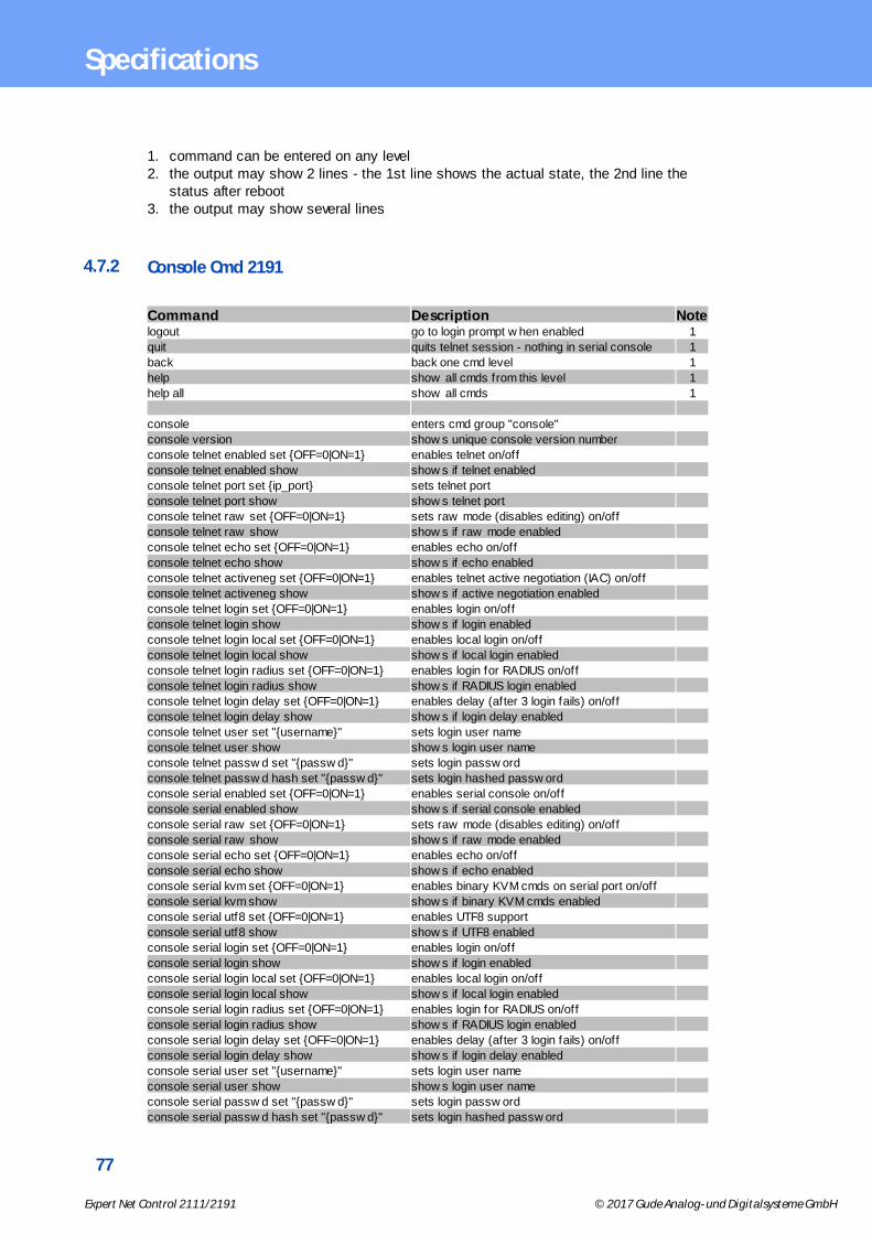
77
Expert Net Control 2111/2191 © 2017 Gude Analog- und Digitalsysteme GmbH
Specifications
1. command can be entered on any level2. the output may show 2 lines - the 1st line shows the actual state, the 2nd line the
status after reboot3. the output may show several lines
4.7.2 Console Cmd 2191
Command Description Notelogout go to login prompt w hen enabled 1
quit quits telnet session - nothing in serial console 1
back back one cmd level 1
help show all cmds from this level 1
help all show all cmds 1
console enters cmd group "console"
console version show s unique console version number
console telnet enabled set {OFF=0|ON=1} enables telnet on/off
console telnet enabled show show s if telnet enabled
console telnet port set {ip_port} sets telnet port
console telnet port show show s telnet port
console telnet raw set {OFF=0|ON=1} sets raw mode (disables editing) on/off
console telnet raw show show s if raw mode enabled
console telnet echo set {OFF=0|ON=1} enables echo on/off
console telnet echo show show s if echo enabled
console telnet activeneg set {OFF=0|ON=1} enables telnet active negotiation (IAC) on/off
console telnet activeneg show show s if active negotiation enabled
console telnet login set {OFF=0|ON=1} enables login on/off
console telnet login show show s if login enabled
console telnet login local set {OFF=0|ON=1} enables local login on/off
console telnet login local show show s if local login enabled
console telnet login radius set {OFF=0|ON=1} enables login for RADIUS on/off
console telnet login radius show show s if RADIUS login enabled
console telnet login delay set {OFF=0|ON=1} enables delay (after 3 login fails) on/off
console telnet login delay show show s if login delay enabled
console telnet user set "{username}" sets login user name
console telnet user show show s login user name
console telnet passw d set "{passw d}" sets login passw ord
console telnet passw d hash set "{passw d}" sets login hashed passw ord
console serial enabled set {OFF=0|ON=1} enables serial console on/off
console serial enabled show show s if serial console enabled
console serial raw set {OFF=0|ON=1} sets raw mode (disables editing) on/off
console serial raw show show s if raw mode enabled
console serial echo set {OFF=0|ON=1} enables echo on/off
console serial echo show show s if echo enabled
console serial kvm set {OFF=0|ON=1} enables binary KVM cmds on serial port on/off
console serial kvm show show s if binary KVM cmds enabled
console serial utf8 set {OFF=0|ON=1} enables UTF8 support
console serial utf8 show show s if UTF8 enabled
console serial login set {OFF=0|ON=1} enables login on/off
console serial login show show s if login enabled
console serial login local set {OFF=0|ON=1} enables local login on/off
console serial login local show show s if local login enabled
console serial login radius set {OFF=0|ON=1} enables login for RADIUS on/off
console serial login radius show show s if RADIUS login enabled
console serial login delay set {OFF=0|ON=1} enables delay (after 3 login fails) on/off
console serial login delay show show s if login delay enabled
console serial user set "{username}" sets login user name
console serial user show show s login user name
console serial passw d set "{passw d}" sets login passw ord
console serial passw d hash set "{passw d}" sets login hashed passw ord

78
Expert Net Control 2111/2191 © 2017 Gude Analog- und Digitalsysteme GmbH
Specifications
email enters cmd group "email"
email enabled set {OFF=0|ON=1} enables email on/off
email enabled show show s if email is enabled
email sender set "{email_addr}" sets email sender address
email sender show show s email sender address
email recipient set "{email_addr}" sets email recipient address
email recipient show show s email recipient address
email server set "{dns_name}" sets email SMTP server address
email server show show s email SMTP server address
email port set {ip_port} sets email SMTP port
email port show show s email SMTP port
email security set {NONE=0|STARTTLS=1|SSL=2} sets SMTP connection security
email security show show s SMTP connection security
email auth set {NONE=0|PLAIN=1|LOGIN=2} sets email authentication
email auth show show email authentication
email user set "{username}" sets SMTP username
email user show show s SMTP username
email passw d set "{passw d}" sets SMTP passw ord
email passw d hash set "{passw d}" sets crypted SMTP passw ord
email testmail send test email
ethernet enters cmd group "ethernet"
ethernet mac show show s MAC address
ethernet link show show s ethernet link state
ethernet phyprefer set {10MBIT_HD=0|
10MBIT_FD=1|100MBIT_HD=2|100MBIT_FD=3}sets preferred speed for PHY Auto Negotiation
ethernet phyprefer showshow s preferred speed for PHY Auto Negoti-
ation
ethernet poe show show s if Pow er-over-Ethernet is activated
extsensor enters cmd group "extsensor"
extsensor {port_num} {TEMP=0|HYGRO=1} value
showshow s sensor value
extsensor {port_num} {TEMP=0|HYGRO=1} label
set "{name}"sets sensor name to label
extsensor {port_num} {TEMP=0|HYGRO=1} label
showshow s label of sensor
extsensor {port_num} name show show s type of sensor
extsensor {port_num} {TEMP=0|HYGRO=1}
events set {off=0|on=1}enables sensor events on/off
extsensor {port_num} {TEMP=0|HYGRO=1}
events showshow s if sensor events are enabled
extsensor {port_num} {TEMP=0|HYGRO=1}
events type set
"{EVT_SYSLOG=0,EVT_SNMP=1,EVT_EMAIL=2,E
VT_SMS=3,EVT_GSMEMAIL=4,EVT_BEEPER=5}"
enables different event types
extsensor {port_num} {TEMP=0|HYGRO=1}
events type showshow s w hat event types are enabled
extsensor {port_num} {TEMP=0|HYGRO=1}
phonebook sms events set "{1..20}"sets for w hat phonebook entries SMS are sent
extsensor {port_num} {TEMP=0|HYGRO=1}
phonebook sms events showshow s for w hat phonebook entries SMS are sent
extsensor {port_num} {TEMP=0|HYGRO=1}
maxval set {num}sets maximum value for sensor
extsensor {port_num} {TEMP=0|HYGRO=1}
maxval showshow s maximum value for sensor
extsensor {port_num} {TEMP=0|HYGRO=1} minval
set {num}sets minimum value for sensor
extsensor {port_num} {TEMP=0|HYGRO=1} minval
showshow s minimum value for sensor
extsensor {port_num} {TEMP=0|HYGRO=1} hyst
set {num}sets hysterese value for sensor
extsensor {port_num} {TEMP=0|HYGRO=1} hyst
showshow s hysterese value for sensor
extsensor {port_num} {TEMP=0|HYGRO=1}
{BELOWMIN=0|ABOVEMIN=1|ABOVEMAX=2|sets Port for Pow er Port Sw itching actions
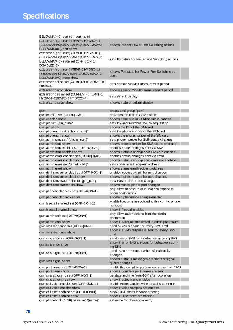
79
Expert Net Control 2111/2191 © 2017 Gude Analog- und Digitalsysteme GmbH
Specifications
BELOWMAX=3} port set {port_num}
extsensor {port_num} {TEMP=0|HYGRO=1}
{BELOWMIN=0|ABOVEMIN=1|ABOVEMAX=2|
BELOWMAX=3} port show
show s Port for Pow er Port Sw itching actions
extsensor {port_num} {TEMP=0|HYGRO=1}
{BELOWMIN=0|ABOVEMIN=1|ABOVEMAX=2|
BELOWMAX=3} state set {OFF=0|ON=1|
DISABLED=2}
sets Port state for Pow er Port Sw itching actions
extsensor {port_num} {TEMP=0|HYGRO=1}
{BELOWMIN=0|ABOVEMIN=1|ABOVEMAX=2|
BELOWMAX=3} state show
show s Port state for Pow er Port Sw itching ac-
tions
extsensor period set {24H=0|12H=1|2H=2|1H=3|
30MIN=4}sets sensor Min/Max measurement period
extsensor period show show s sensor Min/Max measurement period
extsensor display set {CURRENT=0|TEMP1=1|
HYGRO1=2|TEMP2=3|HYGRO2=4}sets default display
extsensor display show show s state of default display
gsm enters cmd group "gsm"
gsm enabled set {OFF=0|ON=1} activates the built-in GSM module
gsm enabled show show s if the built-in GSM module is enabled
gsm pin set "{pin_num}" sets PIN and sw itches the PIN request on
gsm pin show show s the PIN of the SIM card
gsm phonenum set "{phone_num}" sets the phone number of the SIM card
gsm phonenum show show s the phone number of the SIM card
gsm admin sms set "{phone_num}" sets phone number for SMS status changes
gsm admin sms show show s phone number for SMS status changes
gsm admin sms enabled set {OFF=0|ON=1} enables status changes sent via SMS
gsm admin sms enabled show show s if status changes via SMS are enabled
gsm admin email enabled set {OFF=0|ON=1} enables status changes sent via email
gsm admin email enabled show show s if status changes via email are enabled
gsm admin email set "{email_addr}" sets status email recipient address
gsm admin email show show s status email recipient address
gsm dtmf sms pin enabled set {OFF=0|ON=1} enables necessary pin for port changes
gsm dtmf sms pin enabled show show s if pin is needed for port changes
gsm dtmf sms master pin set "{pin_num}" sets master pin for port changes
gsm dtmf sms master pin show show s master pin for port changes
gsm phonebook check set {OFF=0|ON=1}only allow access to calls that correspond to
phonebook entries
gsm phonebook check show show s if phonebook change enabled
gsm freecall enabled set {OFF=0|ON=1}enable functions associated w ith incoming phone
numbers
gsm freecall enabled show show if freecall enabled
gsm admin only set {OFF=0|ON=1}only allow caller actions from the admin
phonenum
gsm admin only show show if caller actions limited to admin phoennum
gsm sms response set {OFF=0|ON=1} send a SMS respone for every SMS cmd
gsm sms response showshow if a SMS respone is sent for every SMS
cmd
gsm sms error set {OFF=0|ON=1} send a error SMS for a defective incoming SMS
gsm sms error showshow if error SMS are sent for defective incom-
ing SMS
gsm sms signal set {OFF=0|ON=1}send status messages w hen signal quality
changes
gsm sms signal showshow s if status messages are sent for signal
quality changes
gsm port name set {OFF=0|ON=1} enable that complete port names are sent via SMS
gsm port name show show if complete port names are sent
gsm sms autosync set {OFF=0|ON=1} get date and time from GSM after pow er-up
gsm sms autosync show show if autosync is enabled
gsm call voice enabled set {OFF=0|ON=1} enable voice samples w hen a call is coming in
gsm call voice enabled show show if voice samples are enabled
gsm call dtmf enabled set {OFF=0|ON=1} allow DTMF tones in voice steering
gsm call dtmf enabled show show if DTM tones are enabled
gsm phonebook {1..20} name set "{name}" set name for phonebook entry
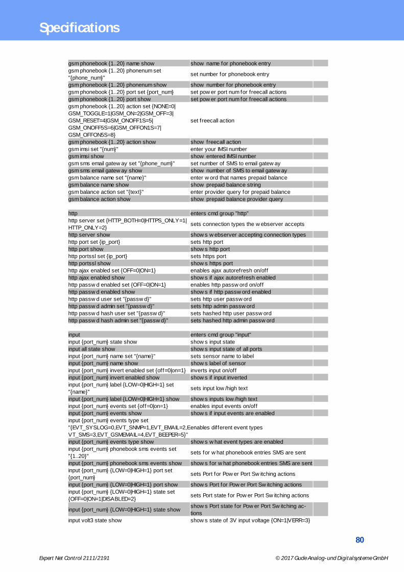
80
Expert Net Control 2111/2191 © 2017 Gude Analog- und Digitalsysteme GmbH
Specifications
gsm phonebook {1..20} name show show name for phonebook entry
gsm phonebook {1..20} phonenum set
"{phone_num}"set number for phonebook entry
gsm phonebook {1..20} phonenum show show number for phonebook entry
gsm phonebook {1..20} port set {port_num} set pow er port num for freecall actions
gsm phonebook {1..20} port show set pow er port num for freecall actions
gsm phonebook {1..20} action set {NONE=0|
GSM_TOGGLE=1|GSM_ON=2|GSM_OFF=3|
GSM_RESET=4|GSM_ONOFF1S=5|
GSM_ONOFF5S=6|GSM_OFFON1S=7|
GSM_OFFON5S=8}
set freecall action
gsm phonebook {1..20} action show show freecall action
gsm imsi set "{num}" enter your IMSI number
gsm imsi show show entered IMSI number
gsm sms email gatew ay set "{phone_num}" set number of SMS to email gatew ay
gsm sms email gatew ay show show number of SMS to email gatew ay
gsm balance name set "{name}" enter w ord that names prepaid balance
gsm balance name show show prepaid balance string
gsm balance action set "{text}" enter provider query for prepaid balance
gsm balance action show show prepaid balance provider query
http enters cmd group "http"
http server set {HTTP_BOTH=0|HTTPS_ONLY=1|
HTTP_ONLY=2}sets connection types the w ebserver accepts
http server show show s w ebserver accepting connection types
http port set {ip_port} sets http port
http port show show s http port
http portssl set {ip_port} sets https port
http portssl show show s https port
http ajax enabled set {OFF=0|ON=1} enables ajax autorefresh on/off
http ajax enabled show show s if ajax autorefresh enabled
http passw d enabled set {OFF=0|ON=1} enables http passw ord on/off
http passw d enabled show show s if http passw ord enabled
http passw d user set "{passw d}" sets http user passw ord
http passw d admin set "{passw d}" sets http admin passw ord
http passw d hash user set "{passw d}" sets hashed http user passw ord
http passw d hash admin set "{passw d}" sets hashed http admin passw ord
input enters cmd group "input"
input {port_num} state show show s input state
input all state show show s input state of all ports
input {port_num} name set "{name}" sets sensor name to label
input {port_num} name show show s label of sensor
input {port_num} invert enabled set {off=0|on=1} inverts input on/off
input {port_num} invert enabled show show s if input inverted
input {port_num} label {LOW=0|HIGH=1} set
"{name}"sets input low /high text
input {port_num} label {LOW=0|HIGH=1} show show s inputs low /high text
input {port_num} events set {off=0|on=1} enables input events on/off
input {port_num} events show show s if input events are enabled
input {port_num} events type set
"{EVT_SYSLOG=0,EVT_SNMP=1,EVT_EMAIL=2,E
VT_SMS=3,EVT_GSMEMAIL=4,EVT_BEEPER=5}"
enables different event types
input {port_num} events type show show s w hat event types are enabled
input {port_num} phonebook sms events set
"{1..20}"sets for w hat phonebook entries SMS are sent
input {port_num} phonebook sms events show show s for w hat phonebook entries SMS are sent
input {port_num} {LOW=0|HIGH=1} port set
{port_num}sets Port for Pow er Port Sw itching actions
input {port_num} {LOW=0|HIGH=1} port show show s Port for Pow er Port Sw itching actions
input {port_num} {LOW=0|HIGH=1} state set
{OFF=0|ON=1|DISABLED=2}sets Port state for Pow er Port Sw itching actions
input {port_num} {LOW=0|HIGH=1} state showshow s Port state for Pow er Port Sw itching ac-
tions
input volt3 state show show s state of 3V input voltage {ON=1|VERR=3}

81
Expert Net Control 2111/2191 © 2017 Gude Analog- und Digitalsysteme GmbH
Specifications
input volt12 state set {OFF=0|VLO=1|VHI=2} sets state of 12V input voltage
input volt12 state showshow s state of 12V input voltage {OFF=0|VLO=1|
VHI=2|VERR=3} incl possible error condition
ip4 enters cmd group "ip4"
ip4 hostname set "{name}" sets device hostname
ip4 hostname show show s device hostname 2
ip4 address set "{ip_address}" sets IPv4 address
ip4 address show show s IPv4 address 2
ip4 netmask set "{ip_address}" sets IPv4 netmask
ip4 netmask show show s IPv4 netmask 2
ip4 gatew ay set "{ip_address}" sets IPv4 gatew ay address
ip4 gatew ay show show s IPv4 gatew ay address 2
ip4 dns set "{ip_address}" sets IPv4 DNS server address
ip4 dns show show s IPv4 DNS server address 2
ip4 dhcp enabled set {OFF=0|ON=1} enables IPv4 DHCP on/off
ip4 dhcp enabled show show s IPv4 DHCP state 2
ip6 enters cmd group "ip6"
ip6 enabled set {OFF=0|ON=1} enables IPv6 on/off
ip6 enabled show show s if IPv6 is enabled 2
ip6 routadv enabled set {OFF=0|ON=1} enables IPv6 router advertisement
ip6 routadv enabled show show s IPv6 router advertisement state 2
ip6 dhcp enabled set {OFF=0|ON=1} enables IPv6 DHCP on/off
ip6 dhcp enabled show show s if IPv6 DHCP is enabled 2
ip6 address show show all IPv6 addresses 3
ip6 gatew ay show show all IPv6 gatew ays 3
ip6 dns show show all IPv6 DNS server 3
ip6 manual enabled set {OFF=0|ON=1} enables manual IPv6 addresses
ip6 manual enabled show show s if manual IPv6 addresses are enabled 2
ip6 manual address {1..4} set "{ip_address}" sets manual IPv6 address
ip6 manual address {1..4} show show s manual IPv6 address 2
ip6 manual gatew ay set "{ip_address}" sets manual IPv6 gatew ay address
ip6 manual gatew ay show show s manual IPv6 gatew ay address 2
ip6 manual dns {1..2} set "{ip_address}" sets manual IPv6 DNS server address
ip6 manual dns {1..2} show show s manual IPv6 DNS server address 2
ipacl enters cmd group "ipacl"
ipacl ping enabled set {OFF=0|ON=1} enables ICMP ping on/off
ipacl ping enabled show show s if ICMP ping enabled
ipacl enabled set {OFF=0|ON=1} enable IP f ilter on/off
ipacl enabled show show s if IP f ilter enabled
ipacl f ilter {ipacl_num} set "{dns_name}" sets IP f ilter {ipacl_num}
ipacl f ilter {ipacl_num} show show s IP f ilter {ipacl_num}
modbus enters cmd group "modbus"
modbus enabled set <off=0/on=1> enables Modbus TCP support
modbus enabled show show s if Modbus is enabled
modbus port set <ip_port> sets Modbus TCP port
modbus port show show s Modbus TCP port
port enters cmd group "port"
port {port_num} state set {OFF=0|ON=1} sets port to new state
port {port_num} state show show s port state
port all state set "{port_list}" {OFF=0|ON=1}sets several ports in one cmd - e.g. port all state
set "1,3,5" 1
port all state {view _mode} show show s all port states in 3 different view modes 3
port {port_num} reset start reset sequence for port
port {port_num} toggle toggles port
port {port_num} batch set {OFF=0|ON=1} w ait
{num_secs} {OFF=0|ON=1}starts batch mode for port
port {port_num} batch cancel cancels batch mode
port {port_num} label set "{name}" sets port label name
port {port_num} label show show s port label name
port {port_num} initstate coldstart set {OFF=0|
ON=1|REMEMBER=2}sets port coldstart initialization

82
Expert Net Control 2111/2191 © 2017 Gude Analog- und Digitalsysteme GmbH
Specifications
port {port_num} initstate coldstart show show s port coldstart initialization
port {port_num} initstate delay set {num} sets port init delay
port {port_num} initstate delay show show s port init delay
port {port_num} gsm pin set "{pin_num}" sets the individual port access code
port {port_num} gsm pin show show s the individual port access code
port {port_num} repow erdelay set {num} sets port repow er delay
port {port_num} repow erdelay show show s port repow er delay
port {port_num} resettime set {num} sets port reset duration
port {port_num} resettime show show s port reset duration
port {port_num} w atchdog enabled set {OFF=0|
ON=1}sets port w atchdog to on/off
port {port_num} w atchdog enabled show show s port w atchdog state
port {port_num} w atchdog mode set {OFF=0|
PORT_RESET=1|IP_MS=2|IP_MS_INV=3}sets port w atchdog mode
port {port_num} w atchdog mode show show s port w atchdog mode
port {port_num} w atchdog type set {WD_ICMP=0|
WD_TCP=1}sets port w atchdog type
port {port_num} w atchdog type show show s port w atchdog type
port {port_num} w atchdog host set "{dns_name}" sets port w atchdog host target
port {port_num} w atchdog host show show s port w atchdog host target
port {port_num} w atchdog port set {ip_port} sets port w atchdog TCP port
port {port_num} w atchdog port show show s port w atchdog TCP port
port {port_num} w atchdog pinginterval set {num} sets port w atchdog ping interval
port {port_num} w atchdog pinginterval show show s port w atchdog ping interval
port {port_num} w atchdog pingretries set {num} sets port w atchdog ping retries
port {port_num} w atchdog pingretries show show s port w atchdog ping retries
port {port_num} w atchdog retrybooting set
{OFF=0|ON=1}sets port w atchdog retry booting to on/off
port {port_num} w atchdog retrybooting show show s port w atchdog retry booting state
port {port_num} w atchdog bootretries set {num} sets port w atchdog retry boot timeout
port {port_num} w atchdog bootretries show how s port w atchdog retry boot timeout
radius enters cmd group "radius"
radius {PRIMARY=0|SECONDARY=1} enabled set
<off=0/on=1>enables radius client
radius {PRIMARY=0|SECONDARY=1} enabled
showshow if radius client enabled
radius {PRIMARY=0|SECONDARY=1} server set
"<dns_name>"sets radius server address
radius {PRIMARY=0|SECONDARY=1} server
showshow s radius server address
radius {PRIMARY=0|SECONDARY=1} passw ord
set "{passw d}"sets radius server shared secret
radius {PRIMARY=0|SECONDARY=1} passw ord
hash set "{passw d}"sets radius server crypted shared secret
radius {PRIMARY=0|SECONDARY=1} auth timeout
set {num_secs}sets server request timeout
radius {PRIMARY=0|SECONDARY=1} auth timeout
showshow s server request timeout
radius {PRIMARY=0|SECONDARY=1} retries set
{num}sets server number of retries
radius {PRIMARY=0|SECONDARY=1} retries
showshow s server number of retries
radius chap enabled set <off=0/on=1> enables CHAP
radius chap enabled show show s if CHAP is enabled
radius message auth set <off=0/on=1> enables request message authentication
radius message auth showshow s if request message authentication is en-
abled
radius default timeout set {num_secs}sets default session timeout (w hen not returned
as Session-Timout Attribute)
radius default timeout show show s default session timeout
snmp enters cmd group "snmp"
snmp port set {ip_port} sets SNMP UDP port
snmp port show show s SNMP UDP port
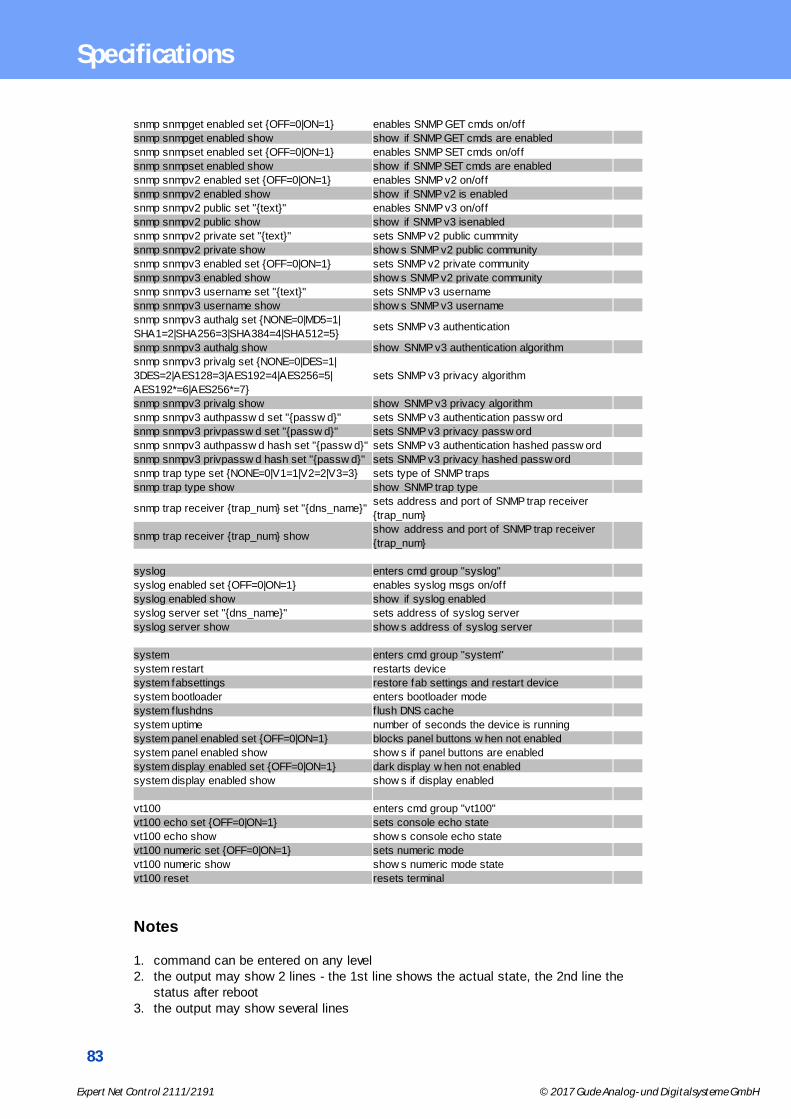
83
Expert Net Control 2111/2191 © 2017 Gude Analog- und Digitalsysteme GmbH
Specifications
snmp snmpget enabled set {OFF=0|ON=1} enables SNMP GET cmds on/off
snmp snmpget enabled show show if SNMP GET cmds are enabled
snmp snmpset enabled set {OFF=0|ON=1} enables SNMP SET cmds on/off
snmp snmpset enabled show show if SNMP SET cmds are enabled
snmp snmpv2 enabled set {OFF=0|ON=1} enables SNMP v2 on/off
snmp snmpv2 enabled show show if SNMP v2 is enabled
snmp snmpv2 public set "{text}" enables SNMP v3 on/off
snmp snmpv2 public show show if SNMP v3 isenabled
snmp snmpv2 private set "{text}" sets SNMP v2 public cummnity
snmp snmpv2 private show show s SNMP v2 public community
snmp snmpv3 enabled set {OFF=0|ON=1} sets SNMP v2 private community
snmp snmpv3 enabled show show s SNMP v2 private community
snmp snmpv3 username set "{text}" sets SNMP v3 username
snmp snmpv3 username show show s SNMP v3 username
snmp snmpv3 authalg set {NONE=0|MD5=1|
SHA1=2|SHA256=3|SHA384=4|SHA512=5}sets SNMP v3 authentication
snmp snmpv3 authalg show show SNMP v3 authentication algorithm
snmp snmpv3 privalg set {NONE=0|DES=1|
3DES=2|AES128=3|AES192=4|AES256=5|
AES192*=6|AES256*=7}
sets SNMP v3 privacy algorithm
snmp snmpv3 privalg show show SNMP v3 privacy algorithm
snmp snmpv3 authpassw d set "{passw d}" sets SNMP v3 authentication passw ord
snmp snmpv3 privpassw d set "{passw d}" sets SNMP v3 privacy passw ord
snmp snmpv3 authpassw d hash set "{passw d}" sets SNMP v3 authentication hashed passw ord
snmp snmpv3 privpassw d hash set "{passw d}" sets SNMP v3 privacy hashed passw ord
snmp trap type set {NONE=0|V1=1|V2=2|V3=3} sets type of SNMP traps
snmp trap type show show SNMP trap type
snmp trap receiver {trap_num} set "{dns_name}"sets address and port of SNMP trap receiver
{trap_num}
snmp trap receiver {trap_num} showshow address and port of SNMP trap receiver
{trap_num}
syslog enters cmd group "syslog"
syslog enabled set {OFF=0|ON=1} enables syslog msgs on/off
syslog enabled show show if syslog enabled
syslog server set "{dns_name}" sets address of syslog server
syslog server show show s address of syslog server
system enters cmd group "system"
system restart restarts device
system fabsettings restore fab settings and restart device
system bootloader enters bootloader mode
system flushdns flush DNS cache
system uptime number of seconds the device is running
system panel enabled set {OFF=0|ON=1} blocks panel buttons w hen not enabled
system panel enabled show show s if panel buttons are enabled
system display enabled set {OFF=0|ON=1} dark display w hen not enabled
system display enabled show show s if display enabled
vt100 enters cmd group "vt100"
vt100 echo set {OFF=0|ON=1} sets console echo state
vt100 echo show show s console echo state
vt100 numeric set {OFF=0|ON=1} sets numeric mode
vt100 numeric show show s numeric mode state
vt100 reset resets terminal
Notes
1. command can be entered on any level2. the output may show 2 lines - the 1st line shows the actual state, the 2nd line the
status after reboot3. the output may show several lines
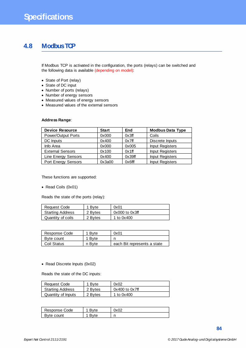
84
Expert Net Control 2111/2191 © 2017 Gude Analog- und Digitalsysteme GmbH
Specifications
4.8 Modbus TCP
If Modbus TCP is activated in the configuration, the ports (relays) can be switched andthe following data is available (depending on model):
· State of Port (relay)· State of DC input· Number of ports (relays)· Number of energy sensors· Measured values of energy sensors· Measured values of the external sensors
Address Range:
Device Resource Start End Modbus Data Type
Power/Output Ports 0x000 0x3ff Coils
DC Inputs 0x400 0x7ff Discrete Inputs
Info Area 0x000 0x005 Input Registers
External Sensors 0x100 0x1ff Input Registers
Line Energy Sensors 0x400 0x39ff Input Registers
Port Energy Sensors 0x3a00 0x6fff Input Registers
These functions are supported:
· Read Coils (0x01)
Reads the state of the ports (relay):
Request Code 1 Byte 0x01
Starting Address 2 Bytes 0x000 to 0x3ff
Quantity of coils 2 Bytes 1 to 0x400
Response Code 1 Byte 0x01
Byte count 1 Byte n
Coil Status n Byte each Bit represents a state
· Read Discrete Inputs (0x02)
Reads the state of the DC inputs:
Request Code 1 Byte 0x02
Starting Address 2 Bytes 0x400 to 0x7ff
Quantity of Inputs 2 Bytes 1 to 0x400
Response Code 1 Byte 0x02
Byte count 1 Byte n
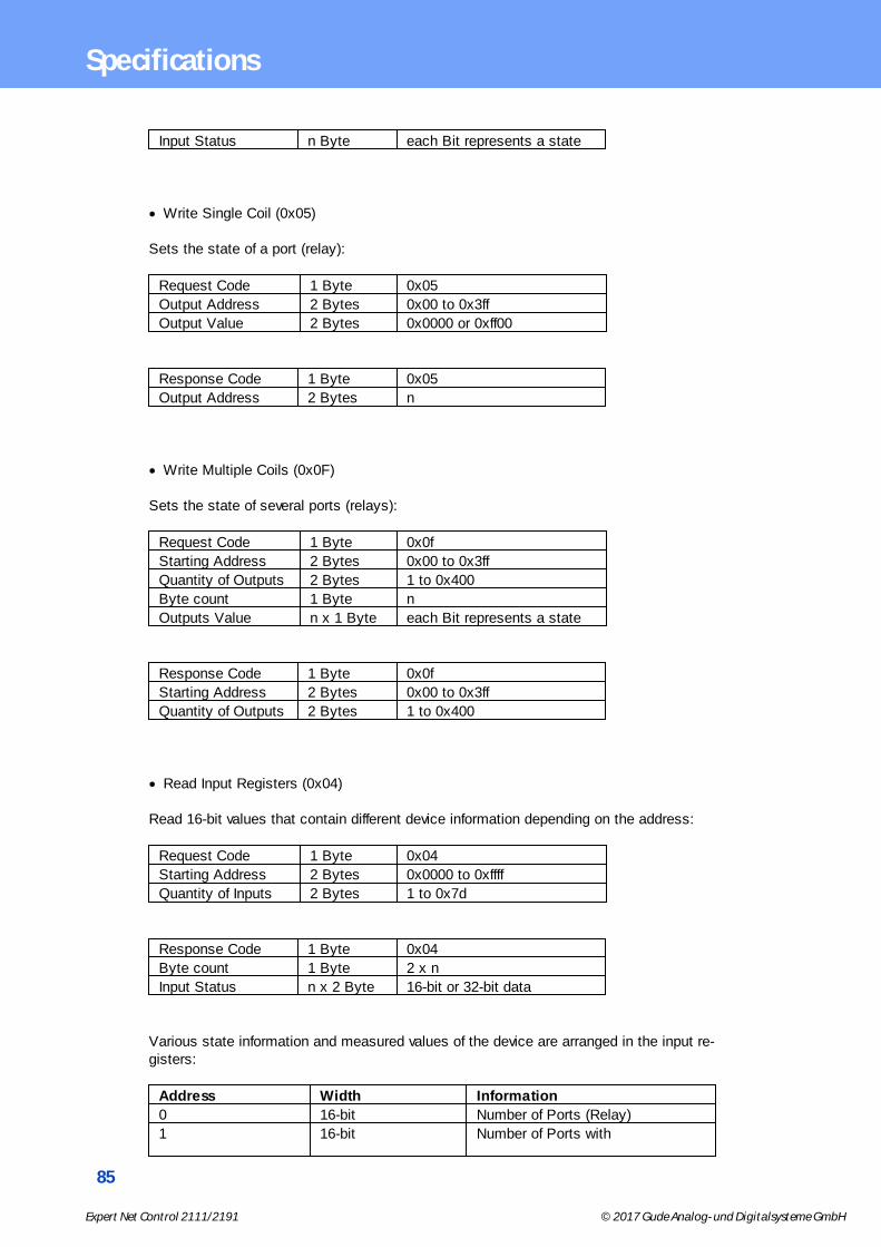
85
Expert Net Control 2111/2191 © 2017 Gude Analog- und Digitalsysteme GmbH
Specifications
Input Status n Byte each Bit represents a state
· Write Single Coil (0x05)
Sets the state of a port (relay):
Request Code 1 Byte 0x05
Output Address 2 Bytes 0x00 to 0x3ff
Output Value 2 Bytes 0x0000 or 0xff00
Response Code 1 Byte 0x05
Output Address 2 Bytes n
· Write Multiple Coils (0x0F)
Sets the state of several ports (relays):
Request Code 1 Byte 0x0f
Starting Address 2 Bytes 0x00 to 0x3ff
Quantity of Outputs 2 Bytes 1 to 0x400
Byte count 1 Byte n
Outputs Value n x 1 Byte each Bit represents a state
Response Code 1 Byte 0x0f
Starting Address 2 Bytes 0x00 to 0x3ff
Quantity of Outputs 2 Bytes 1 to 0x400
· Read Input Registers (0x04)
Read 16-bit values that contain different device information depending on the address:
Request Code 1 Byte 0x04
Starting Address 2 Bytes 0x0000 to 0xffff
Quantity of Inputs 2 Bytes 1 to 0x7d
Response Code 1 Byte 0x04
Byte count 1 Byte 2 x n
Input Status n x 2 Byte 16-bit or 32-bit data
Various state information and measured values of the device are arranged in the input re-gisters:
Address Width Information
0 16-bit Number of Ports (Relay)
1 16-bit Number of Ports with

86
Expert Net Control 2111/2191 © 2017 Gude Analog- und Digitalsysteme GmbH
Specifications
Energy Measurement
2 16-bit Number of Banks
3 16-bit Lines per Bank
4 16-bit Phases per line
5 16-bit Number of Inputs
0x100 to 0x1ff 16-bit (signed) external Sensors
0x400 to 0x39ff 32-bit (signed) Line Energy Sensors
0x3a00 to 0x6fff 32-bit (signed) Port Energy Sensors
External Sensors:
The measured values of the external sensors are coded as fixed-point arithmetic with 1decimal place, they must be divided by 10 to obtain the real measured value. A value of0x8000 means, that no sensor is inserted into the port. The formula for the address is(the port numbers start at zero):
0x100 + Port * 8 + Offset
Offset Sensor Type Unit
0 Temperature 0.1 °C
1 Humidity 0.1 %
For example, the humidity of the second port has the address: 0x100 + 1 * 8 + 1 =0x109
Energy Sensors:
We distinguish the line sensors (which correspond to the input circuits) and the portsensors, which measure the energy that is passed over the switched port. The meas-ured values of the energy sensors are returned as signed 32-bit integers. The high-order16-bits are starting on the even address, followed by the low-order 16-bits on the odd ad-dress. To calculate the address, there are the following formulas (the values for line, portand phase start at zero):
Line: 0x0400 + Line * 0x120 + Phase * 0x60 + Offset * 2
Port: 0x3a00 + Port * 0x120 + Phase * 0x60 + Offset * 2
For devices with only one phase, the phase is set to zero in the formula.
Examples:
"Power Active" for 1st line sensor and 3rd phase: 0x400 + 0 * 0x120 + 2 * 0x60 + 1 * 2 =0x4C2
"Voltage" for 2nd line sensor and single phase device: 0x400 + 1 * 0x120 + 2 * 2 =0x524
"Power Angle" for 4th port sensor and single phase device: 0x3a00 + 3 * 0x120 + 6 * 2 =0x3d6c
Offset Sensor Type Unit

87
Expert Net Control 2111/2191 © 2017 Gude Analog- und Digitalsysteme GmbH
Specifications
0 Absolute Active Energy Wh
1 Power Active W
2 Voltage V
3 Current mA
4 Frequency 0.01 hz
5 Power Factor 0.001
6 Power Angle 0.1 degree
7 Power Apparent VA
8 Power Reactive VAR
9 Absolute Active Energy Resettable Wh
10 Absolute Reactive Energy VARh
11 Absolute Reactive Energy Resettable VARh
12 Reset Time - sec. since last Energy Counter Reset s
13 Forward Active Energy Wh
14 Forward Reactive Energy VARh
15 Forward Active Energy Resettable Wh
16 Forward Reactive Energy Resettable VARh
17 Reverse Active Energy Wh
18 Reverse Reactive Energy VARh
19 Reverse Active Energy Resettable Wh
20 Reverse Reactive Energy Resettable VARh
21 Residual Current mA
22 Neutral Current mA
Depending on the device model, Residual or Neutral Current are not supported
· Read Device Identification (0x2B / 0x0E)
Returns manufacturer name and device identification:
Request Code 1 Byte 0x2b
MEI Type 1 Byte 0x0e
Read Dev ID code 1 Byte 0x01
Object Id 1 Byte 0x00
Response Code 1 Byte 0x2b
MEI Type 1 Byte 0x0e
Read Dev ID code 1 Byte 0x01
Conformity Level 1 Byte 0x01
More Follows 1 Byte 0x00
NextObjectID 1 Byte 0x00
Number of Objects 1 Byte 0x03
Object ID 1 Byte 0x00
Object Length 1 Byte n1
Object Value n1 Bytes "Company Id"
Object ID 1 Byte 0x00
Object Length 1 Byte n2
Object Value n2 Bytes "Product Id"
Object ID 1 Byte 0x00
Object Length 1 Byte n3

88
Expert Net Control 2111/2191 © 2017 Gude Analog- und Digitalsysteme GmbH
Specifications
Object Value n3 Bytes "Product Version"
4.9 Messages
Depending on adjustable events, various messages can be sent from the device. The fol-lowing message types are supported:
· Sending of e-mails· SNMP Traps· Syslog messages
E-Mail messages
Email messages are triggered by the following events:
· Switching of the Power Ports· Exceeding of the max / min values of attached sensors· State change of digital sensor input ports· Exceeding of max / min values of the measured power consumption· Condition change of overvoltage protection
SNMP Traps
SNMP Traps are system messages that are sent via the SNMP protocol to different re-cipients. SNMP traps are triggered by the following events:
· Switching of the Power Ports· Exceeding of the max / min values of attached sensors· State change of digital sensor input ports· Exceeding of max / min values of the measured power consumption· Condition change of overvoltage protection
Syslog messages
Syslog messages are simple text messages that are sent via UDP to a syslog server.Under Linux, normally a syslog daemon is already running (eg. syslog-ng), for MicrosoftWindows systems some freeware programs are available on the market. The syslogmessages are sent for the following events:
· Turning on the device· Enable/disable of syslog in the configuration· Switching of the Power Ports· Exceeding of the max / min values of attached sensors· State change of digital sensor input ports· Exceeding of max / min values of the measured power consumption· Condition change of overvoltage protection

Support

90
Expert Net Control 2111/2191 © 2017 Gude Analog- und Digitalsysteme GmbH
Support
5 Support
You will find the latest product software on our website at www.gude.info available fordownload. If you have further questions about installation or operation of the unit, pleasecontact our support team. Furthermore, we present in our support wiki at www.gude.info/wiki FAQs and configuration examples.
5.1 Data Security
To provide the device with a high level of data security, we recommend the followingmeasures:
· Check that the HTTP password is switched on.· Set up your own HTTP password.· Allow access to HTTP via SSL only.· Authentication and encryption is activated in SNMPv3.· SNMP v2 access is disabled.· enable STARTTLS or SSL in the e-mail configuration.· Archive configuration files securely.· In the IP ACL, enter only the devices that require access to HTTP or SNMP.· Because Telnet is unencrypted, only use it in a secure environment.· Since Modbus TCP is not encrypted, only activate it in a secure environment.· Activate "Message Authentication" in RADIUS.
When accessed from the Internet
· Use a randomized password with at least 32 characters.· If possible, place the device behind a firewall.
5.2 Contact
Gude Analog- und Digitalsysteme GmbHEintrachtstraße 11350668 CologneGermany
Phone: +49-221-912 90 97Fax: +49-221-912 90 98E-Mail: [email protected]: www.gude.info shop.gude.info
Managing Director: Dr.-Ing. Michael Gude
District Court: Köln, HRB-Nr. 17 7 84WEEE-number: DE 58173350Value added tax identification number (VAT): DE 122778228
91
Expert Net Control 2111/2191 © 2017 Gude Analog- und Digitalsysteme GmbH
Support
5.3 FAQ
1. What can I do if the device is no longer accessible?
· If the Status LED is red, the device has no connection to the switch. Unplug and plugthe Ethernet cable. If the Status LED is still red, try other switches. If one uses noswitch, but connects e.g. a laptop directly to the device, make sure you are using acrossover Ethernet cable.
· If the status LED is orange for a longer time after unplugging and plugging the Ethernetcable, then DHCP is configured, but no DHCP server was found in the network. After atimeout, the last IP address is configured manually.
· If there is a physical link (status LED is green) to the device, but you can not accessthe web server, bring the device into bootloader mode and search for it with GBL_Conf.exe. Then check the TCP-IP parameters and change them if necessary.
· If the device is not found by GBL_Conf.exe in bootloader mode, you can reset the set-tings to factory defaults as the last option.
2. Why does it sometimes take so long to configure new SNMPv3 passwords onthe website?
The authentication methods "SHA-384" and "SHA-512" are calculated purely in software,and can not use the crypto hardware. On the configuration page, e.g. "SHA-512", needsup to 45 seconds to calculate the key.
3. Can you enter multiple e-mail recipients?
· Yes. In the E-Mail configuration in the Recipient Address field, it is possible to entermultiple e-mail addresses separated by commas. The input limit is 100 characters.
22

92
Expert Net Control 2111/2191 © 2017 Gude Analog- und Digitalsysteme GmbH
Index
- A -Antenna terminal 9
automated Access 61
- B -Bootloader Mode 16, 21
Button Lock 55
- C -Certificate-Upload 16, 18
clear DNS-Cache 18
Configuration Management 20
Content of Delivery 7
creating certificates 66
- D -Data Security 90
Default Display 55
Description 7
device MIB 64
- E -E-Mail 54
Ethernet connnector 9
- F -Factory Reset 16
FAQ 91
Firmware Upload 16
Firmware-Update 18
- G -GBL_Conf.exe 16
GSM 22
GSM General 55
GSM Misc 56
GSM Phone 57
GSM Provider 58
GSM SIM Card 57
- H -HTTP 44
HTTPS 44
- I -Installation 9
IP-ACL 43, 60
IP-Address 42
IPv6 60
- L -load Configuration 18
- M -Maintenance 16
messages 88
Modbus TCP 84
- O -Ok button 9
Operating the device directly 14
- P -Power Ports 38
- R -Radius 61
Restart 18
RS232 connector 9
- S -Security Advice 7
Select button 9
Sensors 11, 51
signal strength 9
SIM card slot 9
SMS Commands 24
SMS replies 29
SNMP 47, 62
SSL 66

93
Expert Net Control 2111/2191 © 2017 Gude Analog- und Digitalsysteme GmbH
Index
Start-up the device 9
Status LED 9
Status-LED 14
syslog 47
- T -Technical Specifications 11
Terminal Assignment 10
TLS 66
- V -Voice Call 30
- W -Watchdog 39

94
Expert Net Control 2111/2191 © 2017 Gude Analog- und Digitalsysteme GmbH
Expert Net Control 2111/2191
© 2017 Gude Analog- und Digitalsysteme GmbH
7/6/2017


![Sieci GSM - cygnus.tele.pw.edu.plcygnus.tele.pw.edu.pl/~zkotulsk/seminarium/prezentacjaGSM.pdfSystem GSM 400 GSM 850 GSM 900 GSM 1800 GSM 1900 Uplink [MHz] 450.4 - 457.6 ... Odpowiedź](https://img.dokumen.tips/doc/110x75/5ae024237f8b9a97518cdd37/sieci-gsm-zkotulskseminariumprezentacjagsmpdfsystem-gsm-400-gsm-850-gsm-900.jpg)