Embed Size (px)
Citation preview

Best Practices Best Practices
Performance First Client Enablement
Expert Data Acquisition
This document explains the concepts and tools available for passively acquiring network data for analysis. Following the methods outlined here can prevent issues like duplicate packets, asymmetric traffic, and oversubscription of switch ports. These best-practice methods ensure that metrics calculated from captured data will be accurate and reduces unnecessary load on network monitoring tools. This document is intended for network engineers and for the administrators of monitoring platforms who wish to learn which techniques are best suited for their environment.

Pg. 2 Copyright 2008 NetQoS, Inc. 877.835.9575 www.netqos.com
Introduction
Data acquisition is a crucial component of effective network management. The most sophisticated monitoring tools can only report on the data they have. If that data is acquired in an inaccurate manner, whereby network traffic is duplicated or asymmetric, the resulting performance and health metrics can be skewed. NetQoS® SuperAgent®, NetQoS® Unified Communications Monitor, and NetQoS® Trade Monitor only measure and analyze specific types of network traffic; therefore, sending them additional traffic that they are not configured to monitor only adds load to the server, and in extreme cases can cause them to discard packets. In the case of NetQoS GigaStorTM, because it records all traffic that is sent to it, duplicate packets can severely reduce the amount of time that it can retain data, and make packet capture analysis difficult.
Each of the monitoring tools mentioned above performs passive monitoring of network traffic. To enable passive monitoring of a switch, data is typically sourced from multiple Gigabit interfaces and is sent out of a single Gigabit interface. This many-to-one relationship means that it is easily possible to overrun the buffer on the destination interface of the switch. The resulting congestion can cause the switch to discard packets, and the monitoring tool will therefore assume the presence of packet loss, reporting an inaccurate volume and rate count.
We recommend that the destination or capture port used to export mirrored data be a port on the module with the largest buffer size per port. Appendix III of this document contains a list of Cisco 6500 modules and the buffer depth per port on each module. Use this list, along with the show module command, to determine the best location from which to export traffic. The increased buffer depth will decrease the likelihood of packet loss at the switch port, helping to ensure that each packet can be counted.
This document will explain each of the NetQoS-recommended methods available to acquire data from switches, as well as techniques that combine these different methods to gain the benefits of additional filtering and flexibility. By following the practices outlined in this document, you should be able to implement a technique that will give your tools the most accurate representation of your production traffic, ensuring accurate metrics, reduced server load, and increased data storage.
Switch Port Analyzer (SPAN)
The Switch Port Analyzer, or SPAN, feature of Cisco devices allows the user to copy traffic from physical ports on a switch to another port on that switch. SPAN ports are configured by creating a SPAN session comprised of a source and destination.
A monitor session has two attributes:
» Monitor session source • Specifies the physical ports from which the SPAN will copy data. • Specifies the direction of the traffic to be copied: RX, TX, or both (both by default).
» Monitor session destination • Specifies the physical port to which the SPAN will copy data.
The source of the monitor session is composed of three attributes:
» Monitor session number
: Differentiates the monitor session from any others on the switch.
» Monitor session source
: Specifies the ports or VLANs from which the SPAN will copy data.
» Monitor session direction
: Specifies the monitor session direction: RX, TX, or both (both by default).
The source of a monitor session determines the data that will be copied to the destination and has the following caveats: Source ports can be L2 or L3 LAN ports. Both trunk and non-trunk ports can be used at the same time. You cannot configure WAN interfaces to be source ports (such as ATM interfaces), nor should you configure EtherChannel ports as source ports (IOS
Pg. 3 Copyright 2008 NetQoS, Inc. 877.835.9575 www.netqos.com
12.1(13)E and later do not permit it). You cannot mix physical ports and VLANs as sources within the same monitor session – it must be configured either for physical ports or for VLANs.
When you specify the source information using a VLAN or VLAN list (instead of using physical ports), the SPAN function is known as “VLAN SPAN” or “VSPAN”. Sourcing from a VLAN adds every interface in the VLAN to the monitor session.
The destination information is composed of two pieces of information:
» Monitor session number
: Differentiates the monitor session from any others on the switch.
» Monitor session destination
Destination port caveats:
: Specifies the physical port(s) to which the data will be mirrored.
» A destination port can be any physical port. • With release 12.1(13)E and later of Cisco IOS, you can configure the destination port to be a trunk port. This allows you to forward VLAN tags to the data collection device for monitoring purposes. This technique can also be used to filter data leaving the destination port with the “switchport trunk allowed vlan” command.
» A destination port can only service a single SPAN session and cannot be an EtherChannel port.
» A monitor session can have up to 64 destination interfaces.
Example 1: Port SPAN IOS Configuration (config)#monitor session 1 source interface fa2/17
(config)# monitor session 1 destination interface fa2/13
Each monitor session allows you to specify the direction in which the SPAN will be sourced. Source ports can be configured to copy ingress traffic, egress traffic or if no direction is specified the SPAN session will copy both directions. Example 1 does not specify a direction, so interface f2/17 would be sourced from the ingress and egress direction of the switch port. If the intent was only to monitor data received on f2/17, the SPAN session would be configured as in the following example.
Example 2: Ingress-Only IOS Configuration
(config)#monitor session 1 source interface fa2/17 rx
(config)# monitor session 1 destination interface fa2/13
The number of SPAN sessions that a switch can support depends on the switch model and should be taken into consideration when configuring these sessions. For example, the Cisco 6500 Series switch supports four TX sessions and two RX sessions. This means that a Cisco 6500 could support up to six separate SPAN sessions, if each one monitored a single direction as outlined by the limitation. However, the switch will only support two bidirectional sessions because each one consumes a TX session and an RX session.
The Cisco 6500 also supports the presence of multiple destination interfaces on a SPAN session, allowing you to copy production traffic to more than one analyzer. A common use for this feature would be to send one copy of each packet to a performance monitor and another copy to an IDS or other security system.
Pg. 4 Copyright 2008 NetQoS, Inc. 877.835.9575 www.netqos.com
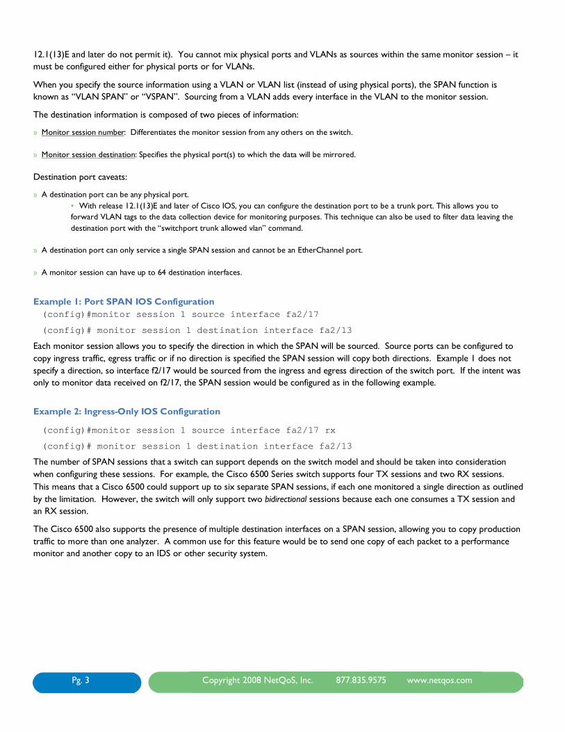
You can check the status of monitor sessions using the show monitor sessions command:
Figure 1
Monitor Session Filters
When the source port of a SPAN session is a trunk port, you can configure a filter for your monitor session in order to monitor only specific VLANs on that port using the “monitor session session-number filter vlan-list” command.
Destination Interface Filters
It is also possible to filter the VLANs leaving a destination port by configuring the interface as a trunk port using the “switchport trunk allowed vlan vlan-list” command. This command allows you to specify which VLANs are allowed to be transmitted by the interface, and when the interface is configured as a destination interface, it will act to filter out traffic. This allows the engineer to allocate VLANs their own destination interfaces, reducing contention for bandwidth and lowering the probability of packet discards due to buffers filling. For more flexible filtering techniques, see the Filtered Port SPAN section of this document.
Using Port SPAN
Because port SPAN allows for individual interfaces to be selected as sources, it is ideally suited for use at access-layer switches. The monitor session should be sourced from interfaces connected to production severs that are hosting business-critical applications. This will ensure that unnecessary data destined for other servers is not seen by the analyzer and does not contend for bandwidth on the SPAN destination.

Pg. 5 Copyright 2008 NetQoS, Inc. 877.835.9575 www.netqos.com
Example 3: Sourcing Port SPAN from Business-Critical Servers
Figure 2
(config)#monitor session 1 source interface f2/17
(config)# monitor session 1 destination interface f2/13
The configuration illustrated in Figure 2 above would capture all traffic going to and from the production server while ignoring traffic to and from the backup server.
Port SPAN and Multi-Tiered Applications
If a packet crosses more than one source interface for a SPAN session, it is copied twice to the monitoring tool, causing additional load on the destination interface and on the collection device, and possibly skewing metrics calculated by the monitoring tool. To avoid duplication when a front-end server talks to a back-end server, only the front tier should be sourced.
Figure 3
Figure 3, above, depicts the port that should be sourced when an application talks between two servers. By sourcing the SPAN from the front-end server, you ensure that the monitoring tool sees data going to and from the client, as well as the application data going to and from the back-end server. If more than two tiers are talking, the interface of every other tier should be a source.

Pg. 6 Copyright 2008 NetQoS, Inc. 877.835.9575 www.netqos.com
Figure 4
Figure 4 depicts a way to avoid packet duplication by sourcing the SPAN from every other tier of a multi-tiered application. Notice that each flow of data is only circled (sourced) once. VSPAN
A VLAN SPAN, or VSPAN, configuration refers to a monitor session sourced from a VLAN instead of from specific interfaces. Sourcing a monitor session from a VLAN results in the addition of every physical interface that is a member of the VLAN as a source. Sourcing from a VLAN is simply a shortcut that allows you to add a group of physical interfaces using a single command. The monitor session is still being sourced from physical interfaces. A VLAN SPAN, or VSPAN, configuration refers to a monitor session sourced from a VLAN instead of from specific interfaces. Sourcing a monitor session from a VLAN results in the addition of every physical interface that is a member of the VLAN as a source. Sourcing from a VLAN is simply a shortcut that allows you to add a group of physical interfaces using a single command. The monitor session is still being sourced from physical interfaces.

Pg. 7 Copyright 2008 NetQoS, Inc. 877.835.9575 www.netqos.com
Example 4: Sourcing from a VLAN
Figure 5, below, depicts the Show VLAN Brief command, indicating that there are two ports in VLAN 10. Sourcing a monitor session from VLAN 10 would result in both ports being sourced.
Figure 5
monitor session 1 source vlan 10 = monitor session 1 source interface fa2/9
monitor session 1 source interface fa2/17
Advantages of VSPAN
VSPAN is easy to configure and does not require you to know the interface to which every server is connected, allowing you to grab large groups of interfaces with a single command. This also means that if servers move ports within the switch or VLAN, the change will be transparent, requiring no change to the SPAN session.
Disadvantages of VSPAN
Because VSPAN does not give you the ability to control which interfaces are sourced, you lose the ability to filter down to specific servers of interest. Instead, you collect traffic on every interface in the VLAN. This configuration increases the likelihood that the destination port of the SPAN will not be able to keep up with the data being sent to it, which can result in congestion and possibly discards at the outbound interface.
Packet Duplication
Because every physical interface of the VLAN is sourced, any packet that travels between two servers on the VLAN is duplicated with a VSPAN configured as the monitor session.
Pg. 8 Copyright 2008 NetQoS, Inc. 877.835.9575 www.netqos.com
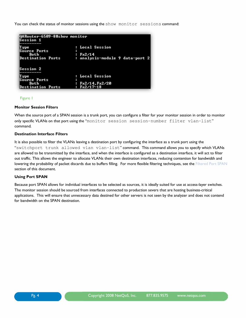
Example 5: Packet Duplication Using VSPAN
Figure 6
(config)#monitor session 1 source vlan 10
(config)# monitor session 1 destination interface f2/13
Duplication can also occur if more than one VLAN is sourced and servers in both VLANs communicate with each other.
Pg. 9 Copyright 2008 NetQoS, Inc. 877.835.9575 www.netqos.com
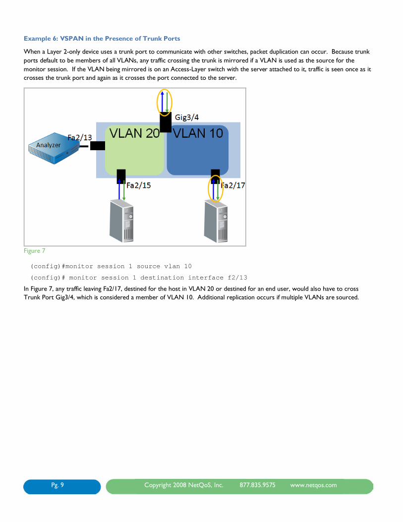
Example 6: VSPAN in the Presence of Trunk Ports
When a Layer 2-only device uses a trunk port to communicate with other switches, packet duplication can occur. Because trunk ports default to be members of all VLANs, any traffic crossing the trunk is mirrored if a VLAN is used as the source for the monitor session. If the VLAN being mirrored is on an Access-Layer switch with the server attached to it, traffic is seen once as it crosses the trunk port and again as it crosses the port connected to the server.
Figure 7
(config)#monitor session 1 source vlan 10
(config)# monitor session 1 destination interface f2/13
In Figure 7, any traffic leaving Fa2/17, destined for the host in VLAN 20 or destined for an end user, would also have to cross Trunk Port Gig3/4, which is considered a member of VLAN 10. Additional replication occurs if multiple VLANs are sourced.

Pg. 10 Copyright 2008 NetQoS, Inc. 877.835.9575 www.netqos.com
Example 7: Sourcing Multiple VLANS in the Presence of Trunk Ports
If VLAN 20 were also a source for the monitor session, any traffic that travels between VLAN 10 and VLAN 20 would be copied:
As it is received by Fa2/17 on VLAN 10
As it is transmitted by Trunk Port Gig3/4 on VLAN 10
As it is received by Trunk Port Gig3/4 on VLAN 20
As it is transmitted by Fa2/15 on VLAN 20
This configuration would lead to quadruplicate packets for certain conversations.
Figure 8 (config)#monitor session 1 source vlan 10
(config)#monitor session 1 source vlan 20
(config)# monitor session 1 destination interface f2/13
Figure 8 shows a Layer 2-only device that uses a trunk port to send traffic to be L3 routed at another device. This configuration would lead to duplication of all traffic between client and server and intra-VLAN. In addition, traffic would be quadruplicated when hosts in VLAN 10 and VLAN 20 needed to communicate with each other.
In this scenario, VLANs should be sourced in only one direction (RX, as there are more RX session available) so that data is only mirrored as it enters the switch.
VSPAN in the Presence of Layer 3 Switches
On devices with Layer 3 routing, a monitor session should never be sourced from a single direction of a VLAN. Because SPAN only monitors data transmitted or received by a physical port, if a packet enters a device from Layer 3 and is routed into the VLAN, it will not be seen until it is transmitted. As a result, if a VSPAN is sourced from a single direction, one side of a TCP conversation will be missing.

Pg. 11 Copyright 2008 NetQoS, Inc. 877.835.9575 www.netqos.com
Example 8: Asymmetric Traffic on a Single-Direction SPAN
Figure 9
(config)#monitor session 1 source vlan 10 rx
(config)# monitor session 1 destination interface f2/13
Figure 9 shows that traffic that enters VLAN 10 from Layer 3 is not seen by this SPAN configuration because there is no physical interface involved. Packets are only seen as they are received by an interface in VLAN 10, so any packets destined to hosts in VLAN 10 (TX) are missed. This can be seen in the packet capture in Figure 9. Any traffic coming from VLAN 20 or from end users would be missed.
Performance Impact of SPAN
On the Cisco 6500 Series switch, each packet that is received by a port is automatically transmitted on the internal switching bus to every line card. Each line card begins to buffer the packet while the Encoded Address Recognition Logic computes the lookup to determine the destination of the packet. Once the EARL process has completed, the packet is flushed from the buffers for which it is not destined, or if no destination is determined from the lookup, the packet is flooded out all ports. Because each packet is already copied to each line card, there is no performance impact when configuring a SPAN destination, as the packet is already being copied throughout the switch.
The non-blocking architecture of the Cisco 4500 switch also allows for the use of SPAN without performance impact.

Pg. 12 Copyright 2008 NetQoS, Inc. 877.835.9575 www.netqos.com
Best Practice Recommendations for Port SPAN and VSPAN
The NetQoS best practice for port SPAN and VSPAN configuration focuses on using methods that limit the amount of unnecessary, non-critical, and duplicated traffic. When using monitor sessions, we recommend that the SPAN be sourced from individual ports whenever possible. Ideally, these should be ports directly connected to the servers hosting applications of interest. In the case of multi-tiered applications, every other tier should be sourced to avoid duplicates. This can be accomplished by diagramming out the flow of the application in advance, and making sure that each flow only crosses one source port.
VSPAN can cause duplicates in many scenarios and is best suited for use on Layer 2-only devices where a single VLAN is being sourced, either ingress-only or egress-only, allowing each packet to be captured only as it enters the switch, or only as it leaves the switch.
VLAN Access Control List
A VACL is an access control list that is applied to a VLAN instead of to an interface. This type of ACL can be used to match traffic, which can then be forwarded to its destination as well as captured (on supported switches) and sent to a monitoring device. VACLs are processed in hardware and are applied to any packet that is bridged on a VLAN or that enters the VLAN from a Layer 3 process.
VACLs are only applied as a packet is initially processed by a VLAN, which prevents duplication for intra-VLAN traffic. VACLs also allow for custom filters to be created limiting the traffic that is captured. VACLs are supported on Cisco 6500 and 4500 (IOS only) series switches (capturing data from a VACL not supported on the 4500 series switch).
Note that all of the VACL capture examples shown in this document capture Layer 3 and 4 traffic only and would not capture L2 only traffic such as spanning tree. VACL capture is therefore not recommended for GigaStor deployments, as the intent should be to capture all traffic, including Layer 2 issues, with the GigaStor.
ACLs
To understand VACLs, we must first describe an ACL. An ACL, or access control list, is an ordered list that is used to match traffic based on specific characteristics. Each line in the list is referred to as an access control entry, or ACE. Each ACE contains a condition to be matched and an action to be taken for any traffic that matches that condition. A packet that does not match any of the ACEs in an ACL will be dropped. This is referred to as the implicit deny all on an ACL.
An ACE can filter on:
» Source IP address
» Destination IP address
» Protocol
» Source protocol port
» Destination protocol port Note that there are additional filtering capabilities for ACLs, but they are beyond the scope of this document. See Cisco’s ACL documentation for details.
An ACE follows the format:
Action protocol source [port] destination [port]
Where the source [port] is the source IP address or subnet and Layer 4 port.

Pg. 13 Copyright 2008 NetQoS, Inc. 877.835.9575 www.netqos.com
Each ACE is directional and uses an inverse network mask notation. In order to permit traffic in both directions for a host or network, you will need two ACEs. The example below shows the ACEs necessary to permit TCP port 80 traffic traveling from and to a 24-bit subnet.
permit tcp 192.168.0.0 0.0.0.255 eq 80 any
permit tcp any 192.168.0.0 0.0.0.255 eq 80
Access Maps
ACLs are applied to VLANs using an access map. An access map can be thought of as a function that can contain multiple ACLs, each with an assigned priority number to specify the order in which they will be processed. In addition, each ACL is also assigned an action to be taken when the ACL is matched,
Within a VLAN access map, whenever a packet matches a permit ACL entry, it is forwarded along its intended path and is not inspected against ACL lines or ACL maps. When a packet matches a deny ACL entry, it will be checked against the next entries, and if a permit exists, it will be forwarded into the network. Only when an ACL exists for a packet, and it does not match any permits within the ACL, will a packet ultimately be dropped.
Figure 10
Figure 10 depicts an access map containing two ACLs. Each ACL has a separate set of actions associated with it. The priority number determines which ACL is processed first (the lowest).
We recommend naming ACLs numerically, and naming access maps in plain text. This strategy helps to prevent confusing the two. A description can be added to each ACL to denote its purpose.

Pg. 14 Copyright 2008 NetQoS, Inc. 877.835.9575 www.netqos.com
Configuring an Access Map
The steps to configure an access map are:
1. Define the access map
a. Formatb.
: VLAN access-map map_name [0-65535] Example
2. Configure the match clause
: vlan access-map SA-Capture 10
a. Formatb.
: match ip address acl_name Example
3. Configure the action clause
: match ip address 101
a. Formatb.
: Action {forward | forward [capture] | drop | redirect } Example
The access map must then be applied to the VLAN using the vlan filter command. Figure 11 depicts an example of an ACL, access map, and VACL being applied:
: action forward
Figure 11
The VACL depicted here was configured to deny ICMP traffic on VLAN 10. The ACL first permits TCP and UDP traffic only, which implicitly denies all other Layer 3 traffic, such as ICMP. The access map named “example” applies the ACL with a priority of 30 (which is arbitrary because there is only one ACL) and specifies that any traffic meeting the ACL must be forwarded to its destination. The vlan filter command applies the access map to VLAN 10.
VACL Capture
VACLs can be used to capture data by specifying an action of forward capture in the VLAN access map. This command tells the switch that any traffic meeting the ACL should be forwarded to its destination, and that a copy should be sent out any interfaces configured as capture ports.
Using this capability, we can make a VACL that will capture all traffic on a VLAN.

Pg. 15 Copyright 2008 NetQoS, Inc. 877.835.9575 www.netqos.com
Example 9: Capturing All Traffic on a VLAN
Figure 12
(config)#access-list 101 permit ip any any
!
(config)#vlan access-map sa_cap 30
(config)#match ip address 101
(config)#action forward capture
!
(config)#vlan filter sa_cap vlan-list 20
!
(config)#interface fa2/13
(config)#switchport capture
In this example, all traffic in VLAN 20 will be forwarded to its destination and a copy sent to any configured capture ports. This is an ideal configuration when you want to capture all traffic on a VLAN because it will not result in duplicates for intra-VLAN traffic, as a VSPAN would. This configuration could be used for sending data to a SuperAgent without filtering out any traffic. This also represents the simplest VACL to implement and there is no risk that the ACL will blocking on production VLANs that is applied to.

Pg. 16 Copyright 2008 NetQoS, Inc. 877.835.9575 www.netqos.com
Example 10: Using VACLs to Filter Traffic Being Captured
Figure 13
(config)# access-list 101 permit tcp any any
!
(config)#access-list 102 permit ip any any
!
(config)# vlan access-map sa_cap 30
(config)# match ip address 101
(config)# action forward capture
!
(config)# vlan access-map sa_cap 40
(config)# match ip address 102
(config)# action forward
!
(config)#vlan filter sa_cap vlan-list 10
!
(config)#interface gig2/13
(config)#switchport capture
Example 10, above, shows how a VACL can be used to filter the traffic that is being captured within a VLAN or VLANs. The first ACL applied in the access map (ACL 101) ensures that any TCP traffic is forwarded to its destination and captured. The second

Pg. 17 Copyright 2008 NetQoS, Inc. 877.835.9575 www.netqos.com
ACL applied (ACL 102) makes sure that any traffic not meeting ACL 102 does not get dropped*. Interface fa2/13 is then configured as a capture port.
This example filters out any traffic that is not TCP, which is useful when capturing data for NetQoS SuperAgent. Using ACLs, it is possible to further limit this traffic to specific ports and/or IP addresses.
*Note that if the second ACL is not applied properly, production traffic that does not meet the first ACL will be dropped as a result. It is a NetQoS best practice to always have VACL configurations reviewed by multiple people before being applied, ideally to a lab environment first. It is also important that everyone involved in this configuration be aware of this risk. The extra review ensures that if traffic is dropped due to a misconfiguration, everyone will immediately know where to look.
Example 11: Denying Backups
A common usage for VACLs is to block out backup traffic that does not need to be seen by SuperAgent. When you wish to deny specific traffic, the access map and ACLs must be done in a different order than example 10. If we were to attempt to deny traffic to and from a backup server and then permit ip any any in a single ACL, the access map would deny the traffic and then permit that same traffic because in an access map, each packet is checked against each entry in the ACL before being discarded.
Instead, we should create an ACL that matches traffic going to or from the backup servers and a pass-through filter:
(config)# access-list 101 permit ip host 192.168.1.1 any
(config)# access-list 101 permit ip any host 192.168.1.1
(config)# access-list 101 permit ip host 192.168.1.2 any
(config)# access-list 101 permit ip any host 192.168.1.2
!
(config)#access-list 102 permit ip any any
!
(config)# vlan access-map sa_cap 30
(config)# match ip address 101
(config)# action forward
!
(config)# vlan access-map sa_cap 40
(config)# match ip address 102
(config)# action forward capture
!
(config)#vlan filter sa_cap vlan-list 10
!
(config)#interface gig2/13
(config)#switchport capture
In Example 11, the backup traffic is matched first and only forwarded; all other traffic is then forwarded and captured. This concept can be expanded upon to create a filter that forwards backup traffic, captures traffic of interest (such as TCP for SuperAgent), and then forwards all IP traffic not meeting the filtering criteria of the first two ACLs. This configuration requires three ACLs, and is a recommend when trying to filter by your production application server IP addresses, but you don’t want the backups of those servers to be sent to SuperAgent to avoid overworking the collection devices.
Advanced Capture Options

Pg. 18 Copyright 2008 NetQoS, Inc. 877.835.9575 www.netqos.com
VACL capture allows for multiple ports to be configured as capture ports. This allows data that is captured to be sent to multiple monitoring devices. One possible use for such a configuration is to send a copy of all traffic to a monitoring solution like GigaStor and another copy to an IDS system. If you are using VACLs to filter traffic and an unfiltered copy of the traffic is needed for an IDS or probe, a monitor session can be configured.
When configuring capture ports, several options are available in the command:
Router(config-if)# switchport capture allowed vlan {add | all | except | remove} vlan_list
By configuring switchport capture, you instruct the switch to send captured traffic from all VLANs out of the capture port. Using the switchport capture allowed vlan … command allows you to specify which VLANS can be sent out a capture port. This command should be used whenever the volume of the traffic being captured is too much to buffer and send on a single interface. To determine whether this situation is occurring, you should monitor the capture port for discards over time using an SNMP poller like NetQoS NetVoyant®.
Example 12: Splitting Captured Traffic across Multiple Capture Ports
Figure 14
Figure 14 shows traffic being captured and filtered from VLAN 50 and 60. Three capture ports are configured, one to accept only VLAN 50, one to accept only VLAN 60, and a third to accept both VLANS.
The first two capture ports would each be connected to SuperAgent collectors to reduce the risk of discards at the switch port and to prevent overloading of the SuperAgent appliance. The third capture port would be connected to a device that does not need every packet to compute its metrics; this could be any device that is using sampling techniques, such as EMC Application Discovery Monitor or certain IDS solutions.

Pg. 19 Copyright 2008 NetQoS, Inc. 877.835.9575 www.netqos.com
Best Practice Recommendations for VACL Capture
NetQoS recommends using VACLs when configuring data acquisition for SuperAgent whenever possible. While they are not ideal for all deployments, their ability to filter down to protocols, subnets, and ports makes VACLs an extremely powerful tool for data acquisition, and helps you get the most performance out of your SuperAgent by reducing unnecessary load. If your organization is willing to implement VACLs, the NetQoS best practice recommendation for each product is:
SuperAgent: Filter to allow only TCP traffic to servers configured for monitoring in SuperAgent. If you are unsure what ports your applications run on start by using server IP addresses. Once you have identified the application ports using SuperAgent’s auto detection capabilities you can modify the VACL to only permit those ports that SuperAgent is configured to monitor. If filtering by server IP address you can also use VACLs to deny specific unmonitored traffic like backups or non critical application servers that are talking to your monitored severs as shown in Example 11.
Unified Communications Monitor: Filter to permit all traffic to and from your Cisco Call Manager(s).
Gigastor: GigaStor is typically used to monitor all traffic passing through a switch for retrospective analysis. The disadvantage of using a VACL to capture traffic for GS is that Layer 2 traffic (spanning tree and other protocols) would not be captured.
As stated above, VACLs should only be used when everyone involved is aware of the risk of misconfiguration and is committed to avoiding this possibility through peer-review of proposed configurations. If VACLs are not an acceptable risk for your organization, you can consider implementing filtered port SPAN to VACL a copy of production traffic, or out of band SPAN, both of which are discussed below.
Remote SPAN (RSPAN)
Remote SPAN is no longer a NetQoS-recommended technique for data collection. We have developed alternative techniques that offer the same benefits of RSPAN with less risk and increased flexibility.
To send data between production devices and aggregate traffic to collection devices, NetQoS recommends out of band SPAN (discussed in the next section, below), which does not require the use of production trunk ports.
If you want to use VACLs for filtering but do not want to VACL a production VLAN, NetQoS recommends using filtered port SPAN, which is also detailed in this document.
Out of Band SPAN
NetQoS has developed out of band SPAN as an alternative method to RSPAN to move data between switches without creating contention for bandwidth on production interfaces, and without the need to provision additional trunk ports.
Out of band SPAN involves creating an isolated VLAN on multiple switches that will only carry monitor session data. This is accomplished by adding the destination interface of a monitor session to a new, Layer 2-only VLAN.
Example 13: Out of Band SPAN
Pg. 20 Copyright 2008 NetQoS, Inc. 877.835.9575 www.netqos.com
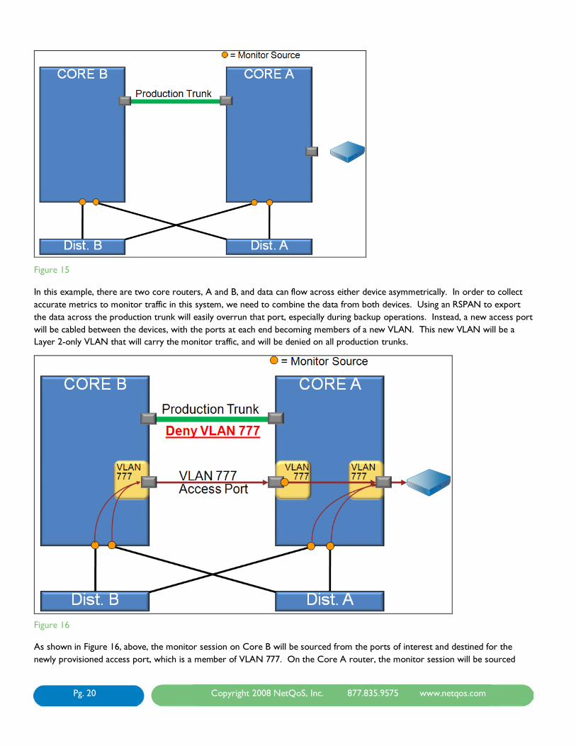
Figure 15
In this example, there are two core routers, A and B, and data can flow across either device asymmetrically. In order to collect accurate metrics to monitor traffic in this system, we need to combine the data from both devices. Using an RSPAN to export the data across the production trunk will easily overrun that port, especially during backup operations. Instead, a new access port will be cabled between the devices, with the ports at each end becoming members of a new VLAN. This new VLAN will be a Layer 2-only VLAN that will carry the monitor traffic, and will be denied on all production trunks.
Figure 16
As shown in Figure 16, above, the monitor session on Core B will be sourced from the ports of interest and destined for the newly provisioned access port, which is a member of VLAN 777. On the Core A router, the monitor session will be sourced

Pg. 21 Copyright 2008 NetQoS, Inc. 877.835.9575 www.netqos.com
from the local ports of interest and from the access port in VLAN 777, which is carrying the monitor data from Core B. The monitor session on Core A will then be destined for the interface connected to the collection device.
By making the destination interface also a member of VLAN 777, we have the option of applying a VACL to filter traffic, and decrease the probability of overrunning the destination interface. The VACL can be applied on both Core B and Core A. Note that a capture command is not necessary on the VACL as it is already being forwarded out of the destination of the monitor session.
Appendices I and II contain detailed steps to safely engineer an out of band SPAN as well as example IOS commands for each step.
Best Practice Recommendation for Out of Band SPAN
Out of band SPAN should be used whenever your collection device is not located on the same switch as the data you are monitoring. Example 13 shows redundant core devices, but an equally likely scenario would involve combining traffic from multiple access switches. In many cases, it is not feasible to purchase a collector for each access switch. Using out of band SPAN, we can combine traffic from two switches and export it to a single collection device, as long as the combined traffic can fit out a single 1-Gigabit port.
The number of devices that you can combine will depend on traffic rates and whether a VACL is being applied to filter traffic on the out of band VLAN, but generally, NetQoS recommends combining traffic from two switches at a time to avoid oversubscription.
Because out of band SPAN uses monitor sessions, all of the same considerations apply to sourcing properly and avoiding duplicate packets. Review the sections on Port SPAN and VSPAN for additional information about these considerations.
Filtered Port SPAN
Out of band SPAN is made possible by adding the destination interface of a monitor session to a new, Layer 2-only VLAN dedicated to monitor traffic. This configuration allows for traffic to be segregated from the production network, and also allows for the filtering of traffic on that VLAN to limit the amount of data sent between switches. This same technique can be used for local data acquisition as well.
Pg. 22 Copyright 2008 NetQoS, Inc. 877.835.9575 www.netqos.com
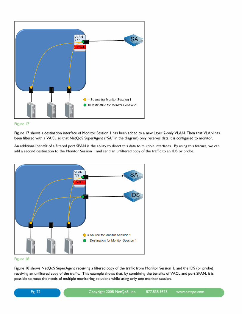
Figure 17
Figure 17 shows a destination interface of Monitor Session 1 has been added to a new Layer 2-only VLAN. Then that VLAN has been filtered with a VACL so that NetQoS SuperAgent (“SA” in the diagram) only receives data it is configured to monitor.
An additional benefit of a filtered port SPAN is the ability to direct this data to multiple interfaces. By using this feature, we can add a second destination to the Monitor Session 1 and send an unfiltered copy of the traffic to an IDS or probe.
Figure 18 Figure 18 shows NetQoS SuperAgent receiving a filtered copy of the traffic from Monitor Session 1, and the IDS (or probe) receiving an unfiltered copy of the traffic. This example shows that, by combining the benefits of VACL and port SPAN, it is possible to meet the needs of multiple monitoring solutions while using only one monitor session.
Pg. 23 Copyright 2008 NetQoS, Inc. 877.835.9575 www.netqos.com
The configuration steps to create a filtered port SPAN will be the same as for out of band SPAN, as listed in Appendix I, without the need to configure multiple devices or monitor changes in CDP. Keep in mind that there is no need to configure a capture command on the VLAN access map. If your intent is to capture VLAN headers for analysis with a GigaStor, filtered port SPAN will not work, because the destination interface must be capture port to capture VLAN headers.
Conclusion
Many options are available for passively acquiring data from switches to use for performance monitoring. This document described the best practice recommendations for each technique and suggested ways of combining these techniques to allow for further filtering, replication, and transferring data between switches.
We always recommend collecting traffic at the same switch where the servers being monitored are connected. This practice ensures that traffic is seen at the same time that it is transmitted to or from the server, making the data as accurate as possible. It also ensures that back-end transactions can be seen by the analyzer.
When using tools that rely on specific traffic types, like NetQoS SuperAgent or NetQoS Trade Monitor, it is a NetQoS best practice to use techniques that filter the traffic to reduce volume as much as possible, ideally to the point where only traffic that is configured to be monitored reaches the tool. This practice includes using:
» Port SPAN and sourcing from only the ports directly connected to servers of interest.
» VACLs to filter down to specific hosts and/or protocols (see Example 10 on page 16).
» Filtered port SPAN to filter traffic from directly connected interfaces down to specific protocols, thus preventing backup operations and activity from other applications from being mirrored (see Figure 17 on page 22).
» Destination filtering or capture port filtering to specify which VLANs exit a destination or capture port. This type of filtering can be used on a distributed SuperAgent system to send VLANs to different Collectors with a single session (see Example 12 on page 18)
When using NetQoS Unified Communications Monitor it is only necessary to send all traffic to and from the Cisco Call Manager or Managers. NetQoS recommends:
» Using a monitor session sourced only from the switchports connected to the Call Managers.
» Use a VACL to filter for all traffic going to and from your Call Manager IP addresses.
When using NetQoS GigaStor to capture data for long-term forensic analysis, we recommend using:
» A technique that captures all traffic of interest on the devices being monitored. Generally this will mean using SPAN sessions, as IP VACL’s will filter out traffic that is not layer 3 (such as STP).
» Configuring destination interfaces as trunk ports to export VLAN headers so that VLAN statistics can be calculated. The interface must be configured as a trunk port before it is configured as a destination interface. The port should also be shut down before it is configured as a trunk to prevent a spanning tree recalculation. This also allows you to filter VLANs that are allowed to leave the destination interface by using the VLAN allowed command on the trunk port. To reduce the risk of packet loss at the destination interface you can use the switchport trunk allowed vlan command to specify which VLANS are sent out of a destination interface. This allows you to split the SPAN across multiple destination interfaces and reduce contention. Because GigaStor has up to eight 1-Gig interfaces or two 10-Gig interfaces, it is well-suited for using multiple destination interfaces.
» If backup traffic is consuming too much storage on the GigaStor filtering should be done on the GigaStor’s active instance to prevent it from writing that data to disk.
When data from multiple switches must be combined in order to get a complete view of all transactions, we recommend using:

Pg. 24 Copyright 2008 NetQoS, Inc. 877.835.9575 www.netqos.com
» Out of band SPAN to send data between switches without having to use trunk ports and to allow data to be filtered down only to critical, monitored applications (see Example 13 on page 19).
When data must be sent to multiple tools such as an IDS, EMC Application Discovery Monitor, or other monitoring solutions, we recommend using:
» Filtered port SPAN to filter traffic being sent to NetQoS tools while still allowing an unfiltered copy to be sent to other systems (see Figure 17 on page 22).
Appendix I: Steps to Safely Engineer Out of Band SPAN
• Open Change Management Case • Initial Device Preparation
• Show interface: Make sure that target port is unused
• Check description • If port is up, check for MAC
address • Look in external, proprietary
switchport DB • Trace the cable
• Copy the switch config to a notepad file • Copy running configuration to startup
configuration • Show cdp neighbor
• Document neighbors – there should be no change
• Shut interface down • Repeat on Device B
• Device Configuration • Device A: • Create VLAN 777 as an active L2 only VLAN • Add Out of Band port to VLAN 777 as an
access port with description “Never route!” • Manually set speed and duplex • Turn off CDP on OoB Interface • Turn on BPDU Filter on OoB interface • Deny VLAN 777 on all trunks/uplinks • Copy running config to startup config • Repeat configuration on Device B • Run Cable • Crossover or Auto MDI-X • Test Cable using: • Test cable-diagnostics tdr • Show port tdr m/p • Bring both OoB ports up • Show int • Show STP VLAN 777 • Show cdp neighbor • Make sure you can’t see the other device • Create monitor session on Device B • Source from desired local ports • Destination to OoB port • VACL VLAN 777 • Forward traffic of interest • Create monitor session on Device A
• Source from OoB port and desired local ports
• Destination to collector port • VACL VLAN 777 • Forward traffic of interest
Best Practices
Performance First Client Enablement
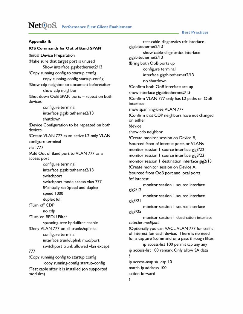
Appendix II:
IOS Commands for Out of Band SPAN
!Initial Device Preparation !Make sure that target port is unused Show interface gigabethernet2/13 !Copy running config to startup config copy running-config startup-config !Show cdp neighbor to document before/after show cdp neighbor !Shut down OoB SPAN ports – repeat on both devices configure terminal interface gigabitethernet2/13 shutdown !Device Configuration to be repeated on both devices !Create VLAN 777 as an active L2 only VLAN configure terminal vlan 777 !Add Out of Band port to VLAN 777 as an access port configure terminal interface gigabitethernet2/13 switchport switchport mode access vlan 777 !Manually set Speed and duplex speed 1000 duplex full !Turn off CDP no cdp !Turn on BPDU Filter
spanning-tree bpdufilter enable !Deny VLAN 777 on all trunks/uplinks configure terminal interface trunk/uplink mod/port switchport trunk allowed vlan except 777 !Copy running config to startup config copy running-config startup-config !Test cable after it is installed (on supported modules)
test cable-diagnostics tdr interface gigabitethernet2/13 show cable-diagnostics interface gigabitethernet2/13 !Bring both OoB ports up configure terminal interface gigabitethernet2/13 no shutdown !Confirm both OoB interface are up show interface gigabitethernet2/13 !Confirm VLAN 777 only has L2 paths on OoB interface show spanning-tree VLAN 777 !Confirm that CDP neighbors have not changed on either !device show cdp neighbor !Create monitor session on Device B, !sourced from of interest ports or VLANs monitor session 1 source interface gig3/22 monitor session 1 source interface gig3/23 monitor session 1 destination interface gig2/13 !Create monitor session on Device A, !sourced from OoB port and local ports !of interest monitor session 1 source interface gig2/12 monitor session 1 source interface gig3/21 monitor session 1 source interface gig3/25 monitor session 1 destination interface collector mod/port !Optionally you can VACL VLAN 777 for traffic of interest !on each device. There is no need for a capture !command or a pass through filter. ip access-list 100 permit tcp any any ip access-list 100 remark Only allow SA data ! ip access-map sa_cap 10 match ip address 100 action forward !

© NetQoS, Inc. 2008. All rights reserved. 26
vlan filter sa_cap vlan-list 777
Appendix III: Buffer Sizes for Cisco 6500 Modules
Module Model Name Module Description Total Buffer Size
Rx Buffer Size Tx Buffer Size
EOL Date
WS-X6816-GBIC 16-port 1000BaseX dual-fabric with GBIC transceivers
512KB 80KB 432KB 1/28/2013
WS-X6748-GE-TX 48-port 10/100/1000T dual-fabric with RJ-45 connectors
1.3MB 166KB 1.2MB
WS-X6748-SFP 48-port 1000BaseX dual-fabric with SFP transceivers
1.3MB 166KB 1.2MB
WS-X6724-SFP 24-port 1000BaseX single-fabric with SFP transceivers
1.3MB 166KB 1.2MB
WS-X6548-GE-TX 48-port 10/100/1000T fabric-enabled with RJ-45 connectors
1.4MB (shared among 8 ports)
185KB (shared among 8 ports)
1.2MB (shared among 8 ports)
WS-X6548V-GE-TX
WS-X6548-GE-45AF
WS-X6516-GBIC 16-port 1000BaseX fabric-enabled with GBIC transceivers
512KB 73KB 439KB 1/15/2011
WS-X6516A-GBIC 16-port 1000BaseX fabric-enabled with GBIC transceivers
1MB 144KB 880KB 1/15/2011
WS-X6516-GE-TX 16-port 10/100/1000T 512KB 73KB 439KB 1/28/2013

© NetQoS, Inc. 2008. All rights reserved. 27
fabric-enabled with RJ-45 connectors
WS-X6408-GBIC 8-port 1000BaseX with GBIC transceivers
512KB 80KB 432KB 3/31/2006
WS-X6408A-GBIC 8-port 1000BaseX with GBIC transceivers
512KB 73KB 439KB 3/31/2006
WS-X6416-GBIC 16-port 1000BaseX with GBIC transceivers
512KB 73KB 439KB 1/15/2011
WS-X6416-GE-MT 16-port 1000BaseSX with MT-RJ connectors
512KB 73KB 439KB 1/15/2011
WS-X6316-GE-TX 16-port 1000BaseT with RJ-45 connectors
512KB 73KB 439KB 7/31/2009
© NetQoS, Inc. 2008. All rights reserved. 28
About the NetQoS Performance Center
The NetQoS Performance Center is a single web-based portal that delivers global visibility into the entire network
infrastructure for the insight to resolve performance issues, troubleshoot infrastructure problems, perform capacity
planning, plan for and validate the effects of change, and track Service Level Agreements (SLAs). The NetQoS
Performance Center provides an integrated view of critical performance data delivered by NetQoS’ best in class
products—SuperAgent® for end-to-end performance data, ReporterAnalyzer™ for traffic analysis, and NetVoyant® for
device performance data. With this visibility, you will make more informed decisions based on precise network
infrastructure usage data, improve staff efficiency, and resolve performance issues rapidly. You can also mitigate risks and
validate the impact of planned changes such as VoIP deployments, MPLS migrations, WAN optimization, QoS policy
implementation, and application rollouts. The NetQoS Performance Center is fast and easy to deploy, and scales to the
largest networks.
About NetQoS
NetQoS is the fastest growing network performance management products and services provider. NetQoS has enabled
hundreds of the world’s largest organizations to take a Performance First approach to network management—the new
vanguard in ensuring optimal application delivery across the WAN. By focusing on the performance of key applications
running over the network and identifying where there is opportunity for improvement, IT organizations can make more
informed infrastructure investments and resolve problems that impact the business. Today, NetQoS is the only vendor
that can provide global visibility for the world’s largest enterprises into all key metrics necessary to take a Performance
First management approach. More information is available at www.netqos.com.
© NetQoS, Inc. 2008. All rights reserved. 29
NetQoS Global Headquarters
5001 Plaza On The Lake
Austin, TX, 78746 United States
Phone: 512.407.9443
Toll-Free: 877.835.9575
Fax: 512.407.8629
NetQoS EMEA
1650 Arlington Business Park
Theale Reading, RG7 4SA United Kingdom
Phone: + 44 (0) 118 929 8032
Fax: + 44 (0) 118 929 8033
NetQoS APAC
NetQoS Singapore Representative Office
Level 21, Centennial Tower
3 Temasek Ave., Singapore 039190
Phone: + 65 6549 7476
Fax: + 65 6549 7001
Website: www.netqos.com
E-mail: [email protected]

© NetQoS, Inc. 2008. All rights reserved. 30
© 2001-2008 NetQoS, Inc. All rights reserved. NetQoS, the NetQoS logo, SuperAgent, and NetVoyant are registered trademarks of NetQoS, Inc.
ReporterAnalyzer and Allocate are trademarks of NetQoS, Inc. Other brands, product names and trademarks are property of their respective owners.
BP rev3 20080730