Embed Size (px)
Citation preview

Honeywell Process Solutions
Experion LX Hardware
Installation Guide EXDOC-X269-en-110A
R110 February 2014
Release 110 Honeywell

R110 Experion LX Hardware Installation Guide ii Honeywell February 2014
Notices and Trademarks
Copyright 2014 by Honeywell International Sárl. Release 110 February 2014
While this information is presented in good faith and believed to be accurate, Honeywell disclaims the implied warranties of merchantability and fitness for a particular purpose and makes no express warranties except as may be stated in its written agreement with and for its customers. In no event is Honeywell liable to anyone for any indirect, special or consequential damages. The information and specifications in this document are subject to change without notice. Honeywell, PlantScape, Experion® PKS, Experion® LX, and TotalPlant are registered trademarks of Honeywell International Inc. Other brand or product names are trademarks of their respective owners.
Honeywell Process Solutions 1860 W. Rose Garden Lane
Phoenix, AZ 85027 USA 1-800 822-7673

R110 Experion LX Hardware Installation Guide iii Honeywell February 2014
About This Document This document provides hardware planning and installation details of EXPERION LX. This documentation is intended for the following audience:
• System engineers who would configure the EXPERION LX modules, and operate the run-time EXPERION LX modules.
• Field engineers who would install and maintain EXPERION LX modules. Knowledge of SCADA systems and experience of working in a Microsoft Windows environment are required.
Release Information
Document Name Document ID Release Number
Publication Date
Experion LX Hardware Installation Guide
EXDOC-X269-en-110A 110A February 2014

Support and Other Contacts
iv Experion LX Hardware Installation Guide R110 Honeywell February 2014
Support and Other Contacts
United States and Canada Contact:
Phone: Fascimile: Mail:
Honeywell Solution Support Center 1-800-822-7673 Calls are answered by dispatcher between 6:00 am and 4:00 pm Mountain Standard Time. Emergency calls outside normal working hours are received by an answering service and returned within one hour. 1-973-455-5000 Honeywell TAC, MS L17 1860 W. Garden Lane Phoenix, AZ, 85027 USA
Europe, Middle East, and Africa (EMEA) Contact:
Phone: Fascimile: Mail:
Honeywell TAC-EMEA +32-2-728-2345 +32-2-728-2696 TAC-BE02 Hermes Plaza Hermeslaan, 1H B-1831 Diegem, Belgium
Pacific Contact:
Phone: Fascimile: Mail: Email:
Honeywell Global TAC – Pacific 1300-364-822 (toll free within Australia) +61-8-9362-9559 (outside Australia) +61-8-9362-9564 Honeywell Limited Australia 5 Kitchener Way Burswood 6100, Western Australia [email protected]
India Contact:
Phone: Fascimile: Mail: Email:
Honeywell Global TAC – India +91-20- 6603-9400 +91-20- 6603-9800 Honeywell Automation India Ltd 56 and 57, Hadapsar Industrial Estate Hadapsar, Pune –411 013, India [email protected]

Support and Other Contacts
R110 Experion LX Hardware Installation Guide v February 2014 Honeywell
Korea Contact:
Phone: Fascimile: Mail: Email:
Honeywell Global TAC – Korea +82-80-782-2255 (toll free within Korea) +82-2-792-9015 Honeywell Co., Ltd 4F, Sangam IT Tower 1590, DMC Sangam-dong, Mapo-gu Seoul, 121-835, Korea [email protected]
People’s Republic of China Contact:
Phone: Mail: Email:
Honeywell Global TAC – China +86- 21-2219-6888 800-820-0237 400-820-0386 Honeywell (China) Co., Ltd 33/F, Tower A, City Center, 100 Zunyi Rd. Shanghai 200051, People’s Republic of China [email protected]
Singapore Contact:
Phone: Fascimile: Mail: Email:
Honeywell Global TAC – South East Asia +65-6580-3500 +65-6580-3501 +65-6445-3033 Honeywell Private Limited Honeywell Building 17, Changi Business Park Central 1 Singapore 486073 [email protected]
Taiwan Contact:
Phone: Fascimile: Mail: Email:
Honeywell Global TAC – Taiwan +886-7-536-2567 +886-7-536-2039 Honeywell Taiwan Ltd. 17F-1, No. 260, Jhongshan 2nd Road. Cianjhen District Kaohsiung, Taiwan, ROC [email protected]
Support and Other Contacts
vi Experion LX Hardware Installation Guide R110 Honeywell February 2014
Japan Contact:
Phone: Fascimile: Mail: Email:
Honeywell Global TAC – Japan +81-3-6730-7160 +81-3-6730-7228 Honeywell Japan Inc. New Pier Takeshiba, South Tower Building, 20th Floor, 1-16-1 Kaigan, Minato-ku, Tokyo 105-0022, Japan [email protected]
Elsewhere Call your nearest Honeywell office.
World Wide Web Honeywell Solution Support Online:
Training Classes
http://www.honeywell.com/ps
Honeywell Automation College: http://www.automationcollege.com
Symbol Definitions
R110 Experion LX Hardware Installation Guide vii February 2014 Honeywell
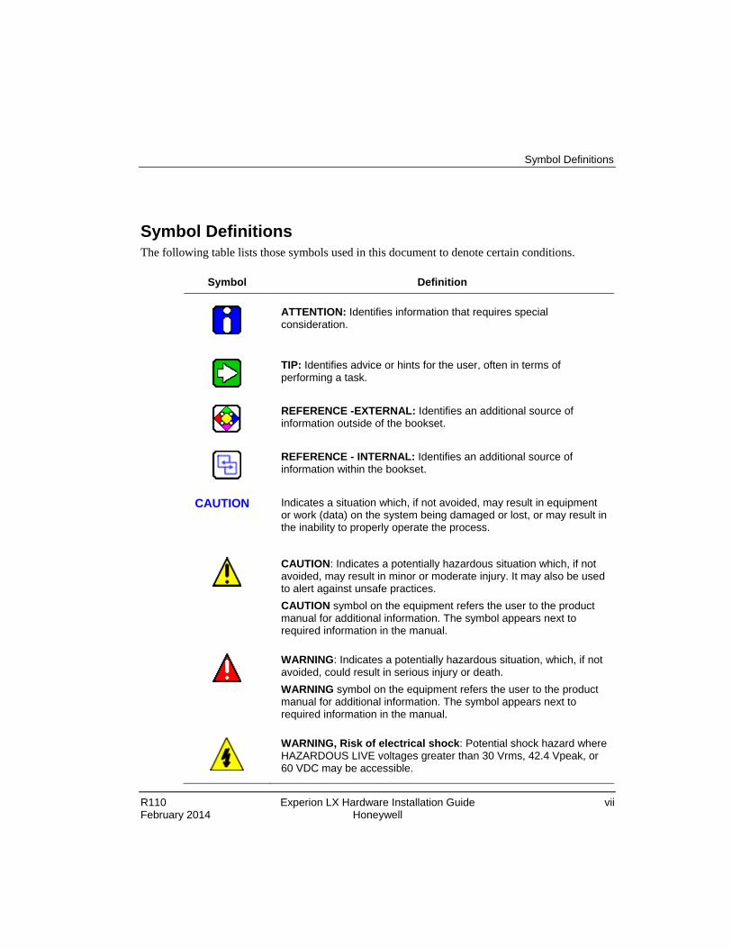
Symbol Definitions The following table lists those symbols used in this document to denote certain conditions.
Symbol Definition
ATTENTION: Identifies information that requires special consideration.
TIP: Identifies advice or hints for the user, often in terms of performing a task.
REFERENCE -EXTERNAL: Identifies an additional source of information outside of the bookset.
REFERENCE - INTERNAL: Identifies an additional source of information within the bookset.
CAUTION
Indicates a situation which, if not avoided, may result in equipment or work (data) on the system being damaged or lost, or may result in the inability to properly operate the process.
CAUTION: Indicates a potentially hazardous situation which, if not avoided, may result in minor or moderate injury. It may also be used to alert against unsafe practices. CAUTION symbol on the equipment refers the user to the product manual for additional information. The symbol appears next to required information in the manual.
WARNING: Indicates a potentially hazardous situation, which, if not avoided, could result in serious injury or death. WARNING symbol on the equipment refers the user to the product manual for additional information. The symbol appears next to required information in the manual.
WARNING, Risk of electrical shock: Potential shock hazard where HAZARDOUS LIVE voltages greater than 30 Vrms, 42.4 Vpeak, or 60 VDC may be accessible.

Symbol Definitions
viii Experion LX Hardware Installation Guide R110 Honeywell February 2014
Symbol Definition
ESD HAZARD: Danger of an electro-static discharge to which equipment may be sensitive. Observe precautions for handling electrostatic sensitive devices.
Protective Earth (PE) terminal: Provided for connection of the protective earth (green or green/yellow) supply system conductor.
Functional earth terminal: Used for non-safety purposes such as noise immunity improvement. NOTE: This connection shall be bonded to Protective Earth at the source of supply in accordance with national local electrical code requirements.
Earth Ground: Functional earth connection. NOTE: This connection shall be bonded to Protective Earth at the source of supply in accordance with national and local electrical code requirements.
Chassis Ground: Identifies a connection to the chassis or frame of the equipment shall be bonded to Protective Earth at the source of supply in accordance with national and local electrical code requirements.

R110 Experion LX Hardware Installation Guide ix Honeywell February 2014
Contents
1. INTRODUCTION ........................................................................... 11
1.1 Overview ....................................................................................................... 11
1.2 1.2 Architecture Overview ........................................................................... 11 Series 8 C300 Controller Overview .......................................................................... 11 Series 8 Profibus Gateway Module Overview ...................................................... 11 Series 8 I/O Overview............................................................................................... 12
2. GENERAL ..................................................................................... 17
2.1 Experion LX Hazardous Certified Modules ................................................ 17
2.2 Certified Experion LX I/O and IOTA Models .............................................. 17
3. EXPERION LX SERIES 8 MOUNTING ......................................... 20
3.1 Installation declarations .............................................................................. 20 Equipment label information ..................................................................................... 21
3.2 Install the Series 8 C300 Controller ............................................................ 29 C300 Controller assembly ........................................................................................ 29 Prerequisites ............................................................................................................ 29 Considerations ......................................................................................................... 30 Installing the Series 8 C300 Controller Procedures .................................................. 30 C300 Controller module and IOTA replacement ....................................................... 32
3.3 Install the Series 8 Profibus Gateway Module........................................... 35 PGM assembly ......................................................................................................... 35 Prerequisites ............................................................................................................ 35 Install the Series 8 Profibus Gateway Module Procedure......................................... 36 PGM IOTA pinouts ................................................................................................... 37
3.4 Install the Series 8 I/O Modules .................................................................. 39 Installing the Series 8 IOTA on the Panel ................................................................. 39 Mounting the I/O module on the IOTA ...................................................................... 40
3.5 Removal and insertion under power .......................................................... 41 Experion LX communication ports ............................................................................ 41
Contents Symbol Definitions
x Experion LX Hardware Installation Guide R110 Honeywell February 2014
4. MAINTENANCE ............................................................................ 43
5. FACTORY MUTUAL CONDITIONS OF USE FOR DIVISION 2/ZONE 2 HAZARDOUS LOCATION INSTALLATION................ 44
5.1 For Use in United State (FM Approvals Standards) .................................. 44
5.2 Canadian Standards ..................................................................................... 44
5.3 European Standards ..................................................................................... 45

R110 Experion LX Hardware Installation Guide 11 Honeywell February 2014
1. Introduction 1.1 Overview
This document contains a description of Experion LX components for installation within Division 2 and Zone 2 hazardous areas. Equipment installed within Zone 2 and Division 2 is intended to be used in places in which explosive atmospheres caused by gases, vapors or mists are unlikely to occur or, if it does occur infrequently and for a short period only. The Experion LX models are certified as nonincendive; Non-Arcing, type nA, and protected sparking, type nC.
For the application of the Experion LX hardware components, the hardware has to be built and installed according to the FM and CSA guidelines for Division 2/Zone 2. This document describes the considerations and requirements for the Experion LX hardware components, which have been certified by FM and CSA for applications in hazardous locations.
1.2 1.2 Architecture Overview The Experion LX platform comprises many different integrated hardware and software solutions depending upon the needs of the application. This pictured architecture is a representation of many of the possible nodes that can be used in the Experion LX architecture. Note that the architecture is highly scalable and not all nodes are necessary or required.
Series 8 C300 Controller Overview Honeywell’s C300 Controller provides powerful and robust control for the Experion LX system. The C300 is a node in operating Honeywell’s field-proven deterministic Control Execution Environment (CEE) core software. The CEE software provides a superior control execution and scheduling environment. Control strategies for each controller node are configured and loaded through a common Control Builder, an easy and intuitive engineering tool. In addition to a standard and robust library of pre-built function blocks and algorithms, the C300 Controller also supports Custom Algorigthm Blocks (CABs). Custom Algorithm Blocks are similar in purpose and structure to the standard function blocks that are distributed with Control Builder. However, CABs have user-defined algorithms and data structures, allowing custom tailored strategies to be developed to specific requirements.
Series 8 Profibus Gateway Module Overview The PROFIBUS Gateway Module provides a common module platform to support the interface to the PROFIBUS DP and the C300 Controller. The PGM is developed in the Series 8 form factor for use with the C300 Controller. The Series 8 form factor employs

1. Introduction 1.2 Architecture Overview
12 Experion LX Hardware Installation Guide R110 Honeywell February 2014
an Input Output Termination Assembly (IOTA) and an electronics module which mounts and connects to the IOTA. As a PROFIBUS gateway, PGM is always a master and communicates with the PROFIBUS compatible slave devices. The PGM mounts in the same fashion and shares all characteristics, power and grounding, certifications, and meets all environmental rating as all other Series 8 components. The PGM is optionally redundant and supports two DP networks per module.
Series 8 I/O Overview This document provides technical information to configure the Series 8 I/O, released with Experion LX. The following Series 8 I/O items are included in this document. • TC/RTD • Analog Input – Single Ended • Analog Input with HART – Single Ended • Analog Input with HART – Differential • Analog Output • Analog Output with HART • Digital Input Sequence of Events • Digital Input 24 VDC • Digital Input Pulse Accumulation • Digital Output 24 VDC • DO Relay Extension Board • C300 Processor • Profibus Gateway
Definitions
• Input Output Termination Assembly (IOTA): An assembly that holds the IOM and the connections for field wiring;
• Input Output Module (IOM): A device that contains most of the electronics required to perform a specific I/O function. The IOM plugs onto the IOTA.
Features
1. Introduction 1.2 Architecture Overview
R110 Experion LX Hardware Installation Guide 13 February 2014 Honeywell
All Series 8 components feature an innovative design that supports enhanced heat management. This unique look provides significant reduction in overall size for the equivalent function. The unique features of Series 8 I/O include: • I/O Module and field terminations are combined in the same area. The I/O Module is
plugged into the IOTA to eliminate the need for a separate chassis to hold the electronics assemblies
• Two level “detachable” terminals for landing the field wiring in the enclosure, providing easier plant installation and maintenance.
• Field power is supplied through the IOTA, with no need for extra power supplies and the associated craft wired marshalling
• Redundancy is accomplished directly on the IOTA without any external cabling or redundancy control devices, by simply adding a second IOM to an IOTA
• For both IOM and IOTA, coated (module numbers starting with 8C) and uncoated (module numbers starting with 8U) options are provided. Conformal coating material is applied to electronic circuitry to act as protection against moisture, dust, chemicals, and temperature extremes. Coated IOM and IOTA are recommended when electronics must withstand harsh environments and added protection is necessary.
The Series 8 inherits the innovative styling of Series C. This styling includes features to facilitate the effective use of control hardware in a systems environment. These features include: • Vertical mounting allows for more effective wiring since most fields wiring
applications require entry from the top or bottom of the systems cabinet. • An “information circle” allows for a quick visual cue to draw the Maintenance
Technician’s eyes to important status information. • “Tilted” design allows for effective heat management within the cabinet enclosure.
Since Series 8 allows for a significant increase in cabinet density, an effective heat management system is critical for high systems availability.
• Input and output circuits are protected from shorts to alleviate the need for in- line fusing, reducing installation and maintenance costs
Series 8 IOTAs combine multiple functions into a single piece of equipment: • Single and redundant configurations • On-board termination of process signals • On-board signal conditioning • On-board connection to appropriate networks (FTE, I/O LINK) • Field power distribution without external marshalling

1. Introduction 1.2 Architecture Overview
14 Experion LX Hardware Installation Guide R110 Honeywell February 2014
• IOM plugs into the IOTA and receives power from the IOTA • The IOTA receives its power through cables from header board.
Series 8 I/O Sizing In virtually all configurations, the C300 controller and Series 8 I/O provides useful, maintainable process equipment connections in a smaller footprint than competitors’ systems. Installing Series 8 I/O modules contributes to overall total installed cost savings. IOTA sizes vary based on the application. In general, an analog module has 16 points and resides on a 6-inch (152mm) IOTA for non-redundant applications and a 12-inch (304mm) IOTA for redundant applications. A discrete module has 32 points and resides on a 9-inch (228mm) IOTA for non-redundant applications and a 12-inch (304mm) IOTA for redundant applications. Specific information on the size of a particular module can be found in the Model Number Table.
I/O Module Functions
• TC/RTD (16pt) – Provides thermocouple (TC) and resistance temperature device (RTD) inputs.
• Analog Input – Single Ended (16pt) - The Analog Input Module supports analog inputs Analog inputs are typically 4-20mA DC for traditional devices.
• Analog Input with HART – Single Ended (16pt) – The Analog Input Module supports both analog and HART inputs. Analog inputs are typically 4-20mA DC for both traditional and HART devices. HART data can be used for status and configuration. HART data, such as the secondary and tertiary variables, can also be used as process control variables.
• Analog Input with HART – Differential (16pt) – The Analog Input Module supports Single Ended or Differential analog inputs, and HART inputs.
• Analog Output (16pt) – The Analog Output Module supports standard 4-20mA DC outputs.
• Analog Output with HART (16pt) – The Analog Output Module supports both standard 4-20mA DC outputs and HART transmitter outputs.
• Digital Input Sequence of Events (32pt) - Accepts 24VDC discrete signals as discrete inputs. The inputs can be time tagged to support 1ms resolution Sequence of Events.
• Digital Input 24 VDC (32pt) – Digital input
1. Introduction 1.2 Architecture Overview
R110 Experion LX Hardware Installation Guide 15 February 2014 Honeywell
sensing for 24V signals • Digital Input Pulse Accumulation (32pt) – Accepts 24VDC discrete signals as
discrete inputs. The first 16 channels can be configured either as Digital Input or Pulse accumulation to support Pulse Accumulation and frequency measurement on per channel basis.
• Digital Output 24 VDC (32 pt) – Current sinking digital outputs. Outputs are electronically short-circuited protected.
• DO Relay Extension Board (32 pt) – Digital output with NO or NC dry contacts. It can be used for low power or high power applications.
Series 8 Field Connections Series 8 Field connections use a standard modular connector. The connector modularity allows for removal and insertion of the field wiring. This significantly reduces installation and maintenance procedures and can assist in field check out. Series 8 field connectors accept up to 12ga AWG / 2.5 mm2 stranded wire.
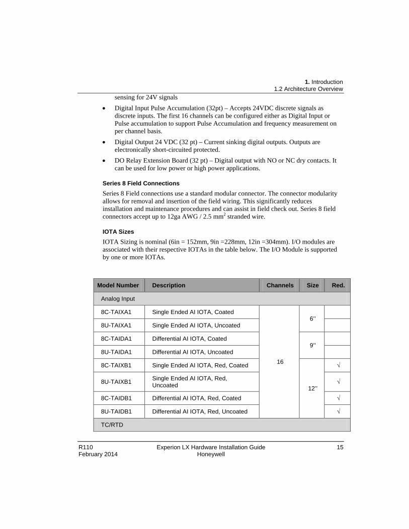
IOTA Sizes IOTA Sizing is nominal (6in = 152mm, 9in =228mm, 12in =304mm). I/O modules are associated with their respective IOTAs in the table below. The I/O Module is supported by one or more IOTAs.
Model Number Description Channels Size Red.
Analog Input
8C-TAIXA1 Single Ended AI IOTA, Coated
16
6’’ 8U-TAIXA1 Single Ended AI IOTA, Uncoated
8C-TAIDA1 Differential AI IOTA, Coated
9’’ 8U-TAIDA1 Differential AI IOTA, Uncoated
8C-TAIXB1 Single Ended AI IOTA, Red, Coated
12’’
√
8U-TAIXB1 Single Ended AI IOTA, Red, Uncoated √
8C-TAIDB1 Differential AI IOTA, Red, Coated √
8U-TAIDB1 Differential AI IOTA, Red, Uncoated √
TC/RTD

1. Introduction 1.2 Architecture Overview
16 Experion LX Hardware Installation Guide R110 Honeywell February 2014
Model Number Description Channels Size Red.
8C-TAIMA1 TC/RTD IOTA, Coated 16 9’’
8U-TAIMA1 TC/RTD IOTA, Uncoated
Analog Output
8C-TAOXA1 Analog Output IOTA, Coated
16
6’’
8U-TAOXA1 Analog Output IOTA, Uncoated
8C-TAOXB1 Analog Output IOTA Red, Coated 12’’
√
8U-TAOXB1 Analog Output IOTA Red, Uncoated √
Digital Input
8C-TDILA1 Digital Input 24VDC IOTA, Coated
32
9’’
8U-TDILA1 Digital Input 24VDC IOTA, Uncoated
8C-TDILB1 Digital Input 24VDC IOTA Red. Coated
12’’ √
8C-TDILB1 Digital Input 24VDC IOTA Red. Uncoated √
Digital Output
8C-TDODA1 Digital Output IOTA, Coated
32
9’’
8U-TDODA1 Digital Output IOTA, Uncoated
8C-TDODB1 Digital Output IOTA Red, Coated 12’’
√
8U-TDODB1 Digital Output IOTA Red, Uncoated √
C300 Control Processor
8C-TCNTA1 Series 8 C300 ControllerIOTA, Coated
8U-TCNTA1 Series 8 C300 ControllerIOTA, Uncoated
Profibus Gateway
2. General Experion LX Hazardous Certified Modules
R110 Experion LX Hardware Installation Guide 17 February 2014 Honeywell
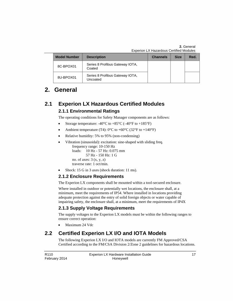
Model Number Description Channels Size Red.
8C-BPOX01 Series 8 Profibus Gateway IOTA, Coated
8U-BPOX01 Series 8 Profibus Gateway IOTA, Uncoated
2. General
2.1 Experion LX Hazardous Certified Modules 2.1.1 Environmental Ratings The operating conditions for Safety Manager components are as follows: • Storage temperature: -40°C to +85°C (–40°F to +185°F) • Ambient temperature (T4): 0°C to +60°C (32°F to +140°F) • Relative humidity: 5% to 95% (non-condensing) • Vibration (sinusoidal): excitation: sine-shaped with sliding freq.
frequency range: 10-150 Hz loads: 10 Hz - 57 Hz: 0.075 mm 57 Hz - 150 Hz: 1 G no. of axes: 3 (x, y, z) traverse rate: 1 oct/min.
• Shock: 15 G in 3 axes (shock duration: 11 ms).
2.1.2 Enclosure Requirements The Experion LX components shall be mounted within a tool-secured enclosure. Where installed in outdoor or potentially wet locations, the enclosure shall, at a minimum, meet the requirements of IP54. Where installed in locations providing adequate protection against the entry of solid foreign objects or water capable of impairing safety, the enclosure shall, at a minimum, meet the requirements of IP4X
2.1.3 Supply Voltage Requirements The supply voltages to the Experion LX models must be within the following ranges to ensure correct operation: • Maximum 24 Vdc
2.2 Certified Experion LX I/O and IOTA Models The following Experion LX I/O and IOTA models are currently FM Approved/CSA Certified according to the FM/CSA Division 2/Zone 2 guidelines for hazardous locations.

2. General Certified Experion LX I/O and IOTA Models
18 Experion LX Hardware Installation Guide R110 Honeywell February 2014
Model Model Description 8C-PCNTA02 Series 8 C300 Controller - Coated 8U-PCNTA02 Series 8 C300 Controller- Uncoated
C-IP0102
Profibus Gateway - Coated
U-IP0102
Profibus Gateway - Uncoated
8C-PAIMA1 Thermocouple/RTD - Coated 8U-PAIMA1 Thermocouple/RTD - Uncoated 8C-PAINA1 Analog Input - Coated 8U-PAINA1 Analog Input - Uncoated 8C-PAIHA1 Analog Input with Hart Single Ended - Coated 8U-PAIHA1 Analog Input with Hart Single Ended - Uncoated 8C-PAIH54 Analog Input with Hart Differential - Coated 8U-PAIH54 Analog Input with Hart Differential - Uncoated 8C-PAONA1 Analog Output - Coated 8U-PAONA1 Analog Output - Uncoated 8C-PAOHA1 Analog Output with Hart - Coated 8U-PAOHA1 Analog Output with Hart - Uncoated 8C-PDISA1 Digital Input Sequence of Events - Coated 8U-PDISA1 Digital Input Sequence of Events - Uncoated 8C-PDILA1 Digital Input 24VDC - Coated 8U-PDILA1 Digital Input 24VDC - Uncoated 8C-PDIPA1 Digital Input Pulse Accumulation - Coated 8U-PDIPA1 Digital Input Pulse Accumulation - Uncoated 8C-PDODA1 Digital Output 24VDC - Coated 8U-PDODA1 Digital Output 24VDC - Uncoated 8C-SDOX01 DO Relay Extension Board - Coated 8C-SHEDA1 Power Distribution Header - Coated 8U-SHEDA1 Power Distribution Header - Uncoated 8C-TCNTA1 Series 8 C300 Controller I/O Termination Assembly, coated 8U-TCNTA1 Series 8 C300 Controller I/O Termination Assembly, uncoated 8C-TPOXA1 Profibus Gateway I/O Termination Assembly Coated 8U-TPOXA1 Profibus Gateway I/O Termination Assembly Uncoated 8C-TAIMA1, Thermocouple/RTD I/O Termination Assembly,Coated 8U-TAIMA1, Thermocouple/RTD I/O Termination Assembly,Uncoated

2. General Certified Experion LX I/O and IOTA Models
R110 Experion LX Hardware Installation Guide 19 February 2014 Honeywell
Model Model Description
8C-TAIXA1 Analog Input I/O Termination Assembly Non Redundant Coated
8U-TAIXA1 Analog Input I/O Termination Assembly Non Redundant Uncoated
8C-TAIXB1 Analog Input I/O Termination Assembly Redundant Coated 8U-TAIXB1 Analog Input I/O Termination Assembly Redundant Uncoated
8C-TAIDA1 Analog Input with Hart Differential I/O Termination Assembly Non Redundant Coated
8U-TAIDA1 Analog Input with Hart Differential I/O Termination Assembly Non Redundant Uncoated
8C-TAIDB1 Analog Input with Hart Differential I/O Termination Assembly Redundant Coated
8C-TAIDB1 Analog Input with Hart Differential I/O Termination Assembly Redundant Uncoated
8C-TAOXA1 Analog Output I/O Termination Assembly Non Redundant Coated
8U-TAOXA1 Analog Output I/O Termination Assembly Non Redundant Uncoated
8C-TAOXB1 Analog Output I/O Termination Assembly Redundant Coated 8U-TAOXB1 Analog Output I/O Termination Assembly Redundant Uncoated 8C-TDILA1 Digital Input I/O Termination Assembly Non Redundant Coated
8U-TDILA1 Digital Input I/O Termination Assembly Non Redundant Uncoated
8C-TDILB1 Digital Input I/O Termination Assembly Redundant Coated 8U-TDILB1 Digital Input I/O Termination Assembly Redundant Uncoated
8C-TDODA1 Digital Output I/O Termination Assembly Non Redundant Coated
8U-TDODA1 Digital Output I/O Termination Assembly Non Redundant Uncoated
8C-TDODB1 igital Output I/O Termination Assembly Redundant Coated
8U-TDODB1 Digital Output I/O Termination Assembly Redundant Uncoated
ATTENTION Approval rating for Experion LX Series 8 modules are list below: • FM: Class I, Division 2, Group A,B,C,D; T4
Class I, Zone 2, AEx/Ex nA IIC T4 Gc • CSA: Class I, Division 2, Group A,B,C,D; T4

3. Experion LX Series 8 Mounting Installation declarations
20 Experion LX Hardware Installation Guide R110 Honeywell February 2014
Class I, Zone 2, Ex nA IIC T4 Gc • ATEX: II 3G Ex nA IIC T4 Gc Classification of maximum surface temperatures for Group II electrical equipment are:
Temperature class Maximum surface temperature ℃
T1 450
T2 300
T3 200
T4 135
T5 100
T6 85
3. Experion LX Series 8 Mounting
3.1 Installation declarations
ATTENTION This equipment shall be installed in accordance with the requirements of the National Electrical Code (NEC), ANSI/NFPA 70, or the Canadian Electrical Code (CEC), C22.1. It is intended to be mounted within an enclosure or suitable environment acceptable to the local "authority having jurisdiction," as defined in the NEC, or "authorized person" as defined in the CEC.

3. Experion LX Series 8 Mounting Installation declarations
R110 Experion LX Hardware Installation Guide 21 February 2014 Honeywell
ESD HAZARD Electrostatic discharge can damage integrated circuits or semiconductors if you touch connector pins or tracks on a printed wiring board. Follow these guidelines when you handle any electronic component: • Touch a grounded object to discharge static potential
• Wear an approved wrist-strap grounding device • Do not touch the wire connector or connector pins • Do not touch circuit components inside a component • If available, use a static safe workstation
• When not in use, keep the component in its static shield box or bag
WARNING Unless the location is known to be non-hazardous, do not connect or disconnect cables or install or remove components while the control system is powered include connecting or disconnecting the IOM from the IOTA. That does not, if not avoided, may result in minor or moderate injury.
Mounting considerations in this section apply to Experion LX systems that include:
Equipment label information The following information can be found on the label of Experion LX Series 8 as shown below:
IOM Label
Figure 1 IOM Label
Item Description
1 Place of production
2 Serial No.

3. Experion LX Series 8 Mounting Installation declarations
22 Experion LX Hardware Installation Guide R110 Honeywell February 2014
3 Model No.
4 Part No.
5 Maximum Power Consumption
6 Operating temperature
7 Mac address
8 Standards and certifications
9 Version information of factory firmware and hardware
TIP The date of manufacture can be identified in the Serial No.
IOTA Label
You can find the standards and certifications as well as operating temperature on the IOTA label.
• Typical layout of the back panel on which Experion LX Series 8 modules are installed, see the following figure:

3. Experion LX Series 8 Mounting Installation declarations
R110 Experion LX Hardware Installation Guide 23 February 2014 Honeywell
Item Description
A >=110MM
B >=5 MM
C >=30 MM
D >=5 MM
E >=125 MM
F =2.54 MM

3. Experion LX Series 8 Mounting Installation declarations
24 Experion LX Hardware Installation Guide R110 Honeywell February 2014
Item Description
A 156.5 MM (MAX. HEIGHT ON BACK PANEL)
B >= 150.0 MM (RECOMMENDED DISTANCE FROM MODULE TO CABINET DOOR)
TIP: Tighten the IOTA mounting screw with the torque between 0.4 and 0.5 Nm.

3. Experion LX Series 8 Mounting Installation declarations
R110 Experion LX Hardware Installation Guide 25 February 2014 Honeywell
Number Description
A >= 5 MM
B >= 5 MM
C >= 5 MM
D >= 5 MM
E = 3 MM
• IO link and power cable requirements: Refer to the following picture for the IO link and power cable link:

3. Experion LX Series 8 Mounting Installation declarations
26 Experion LX Hardware Installation Guide R110 Honeywell February 2014
CAUTION
Due to the capacity of the combo cable: • Up to 2 cables can be connected in a series in a column; up to 6
modules can be connected in a cable. • When the system supply is use to charge, if DO modules are
installed in the combo cable, AO modules are forbidden to install in the combo cable; if AO modules are installed in the combo cable, DO modules are forbidden to install in the combo cable with up to 5 DO modules connected in the cable.
• Refer to the following picture for 24VDC power supply connections to the header board
Figure 2 Power Supply terminal on the header board
Number Description
1 Power Supply Port
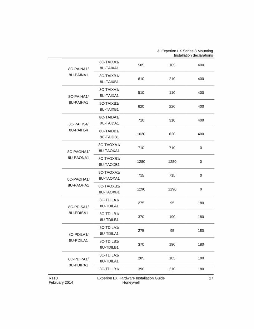
• Limit of current rating (drops) , refer to the following table for the maximum current
draw rating:
IO Module IOTA Module
Maximum Current Draw
Rating System Power Supply (mA@24VDC)
Maximum Current
Values(mA@ 24VDC)
Maximum Current Field Supply(mA @ 24 VDC)
8C-PCNT02/ 8U-PCNT02
8C-TCNTA1/ 8U-TCNTA1
320 320 0
8C-IP0102/ 8U-IP0102
8C-TPOXA1/ 8U-TPOXA1
430 430 0
8C-PAIMA1/ 8U-PAIMA1
8C-TAIMA1/ 8U-TAIMA1
120 120 0
① ① ①
3. Experion LX Series 8 Mounting Installation declarations
R110 Experion LX Hardware Installation Guide 27 February 2014 Honeywell
8C-PAINA1/ 8U-PAINA1
8C-TAIXA1/ 8U-TAIXA1
505 105 400
8C-TAIXB1/ 8U-TAIXB1
610 210 400
8C-PAIHA1/ 8U-PAIHA1
8C-TAIXA1/ 8U-TAIXA1
510 110 400
8C-TAIXB1/ 8U-TAIXB1
620 220 400
8C-PAIH54/ 8U-PAIH54
8C-TAIDA1/ 8U-TAIDA1
710 310 400
8C-TAIDB1/ 8C-TAIDB1
1020 620 400
8C-PAONA1/ 8U-PAONA1
8C-TAOXA1/ 8U-TAOXA1
710 710 0
8C-TAOXB1/ 8U-TAOXB1
1280 1280 0
8C-PAOHA1/ 8U-PAOHA1
8C-TAOXA1/ 8U-TAOXA1
715 715 0
8C-TAOXB1/ 8U-TAOXB1
1290 1290 0
8C-PDISA1/ 8U-PDISA1
8C-TDILA1/ 8U-TDILA1
275 95 180
8C-TDILB1/ 8U-TDILB1
370 190 180
8C-PDILA1/ 8U-PDILA1
8C-TDILA1/ 8U-TDILA1
275 95 180
8C-TDILB1/ 8U-TDILB1
370 190 180
8C-PDIPA1/ 8U-PDIPA1
8C-TDILA1/ 8U-TDILA1
285 105 180
8C-TDILB1/ 390 210 180

3. Experion LX Series 8 Mounting Install the Series 8 C300 Controller
28 Experion LX Hardware Installation Guide R110 Honeywell February 2014
8U-TDILB1
8C-PDODA1/ 8U-PDODA1
8C-TDODA1/ 8U-TDODA1
3465 105 3360
8C-TDODB1/ 8U-TDODB1
3570 210 3360
8C-SDOX01 1010 1010 0
• General grounding guidelines:
WARNING The grounding system must be installed in accordance with the National Electrical Code (NEC), Canadian Electrical Code (CEC), and any other applicable electrical codes (to include: IEEE-142; Lightning Protection Institute Installation Code LPI-175; NFPA-78 (ANSI); IEEE Std. 142-1972). A broken or high resistance safety ground creates a potentially lethal situation, especially in equipment that incorporates line filters. The line filters include appreciable line-to-chassis capacitance. As a result, if the green or green/yellow ground wire is not intact, a person touching the equipment and ground can receive a serious and possibly fatal shock.
Adequate grounding is important for safety considerations and for reducing electromagnetic noise interference. All earth-ground connections must be permanent and provide a continuous low impedance path to earth ground for induced noise currents and fault currents. Refer to the following guidelines when considering the grounding requirements of your system:
For safe operation of your equipment, a high-integrity grounding system must be installed as part of the building's wiring system.
− An equipment ground wire must be enclosed with the circuit conductors (phase and neutral wires),
− The isolated ground wire must run directly from the outlet to the power source − The size of the ground conductor must be the same as, or larger, than the circuit
conductors supplying the equipment − The ground conductor must be securely bonded to the building-ground electrode − Grounding provisions must be in accordance with the NEC, CEC, and any other
local codes.

3. Experion LX Series 8 Mounting Install the Series 8 C300 Controller
R110 Experion LX Hardware Installation Guide 29 February 2014 Honeywell
3.2 Install the Series 8 C300 Controller C300 Controller assembly The C300 Controller consists of an Input/Output Terminal Assembly (IOTA) board and the controller module which is housed within a plastic cover and is mounted on the IOTA board. The Controller assembly is installed in a control cabinet on vertically-mounted channels specifically for Series 8 control hardware. C300 Controller IOTA Board Connector Summary is show below:
C300 IOTA Board Description
F1 Fuse
IOL1A, IOL1B (Gray cable) IOL2A, IOL2B (Violet cable)
Redundant IOLINK connectors for IOLINK 1 and IOLINK 2 IOLink A cable connectors are Yellow. IOLink B cable connectors are Green.
FTE A, FTE B Fault Tolerant Ethernet (FTE) network connectors FTE A network cable connectors are Yellow. FTE B network cable connectors are Green.
REDUNDANCY Redundant private path cable connector. Redundancy cable connector is Orange
MEMORY HOLD-UP Battery Backup cable connector Battery cable is a twisted pair.
GPS (Currently not used) GPS cable connector
FTE DEVICE INDEX 99, 10, 1
Three rotary decimal switches used to set the FTE network address (Device Index) of the controller.
Prerequisites Before you install the C300 Controller you should have: A control cabinet installed with panel for mounting Series 8 control hardware. A power supply and RAM Charger Assembly installed in the cabinet.
Following are the parts included:

3. Experion LX Series 8 Mounting Install the Series 8 C300 Controller
30 Experion LX Hardware Installation Guide R110 Honeywell February 2014
C300 Controller assembly (control module with IOTA board and mounting hardware) 2 STP Cat5 Ethernet cables (one Yellow cable, one Green cable) 2 or 4 IOLink cable assemblies for connecting on-board IO Link interface if the controller is supporting Series 8 I/O Ensure the cabinet enclosure is connected to a protective earth ground using at least #8 AWG solid copper wire. There should be metal to metal contact between the grounding bus bar and the enclosure as well as the channel.
Considerations When installing a redundant controller pair consisting of a primary and a partner secondary controller: The secondary controller should be installed in the same cabinet as the primary controller. The secondary controller may be installed on a separate channel from the primary controller.
Installing the Series 8 C300 Controller Procedures To install a C300 Controller, perform the following steps.
Step Action
1 Refer to appropriate site location drawings for the specified controller installation location, controller Device Index (FTE address) and wiring diagrams.
2 Identify the mounting location on channel and align mounting holes in IOTA with screw hole locations on the channel.

3. Experion LX Series 8 Mounting Install the Series 8 C300 Controller
R110 Experion LX Hardware Installation Guide 31 February 2014 Honeywell
Step Action
3 Be sure component side of IOTA is facing up. Refer to the figure below. Assemble mounting screws, washers and spacers provided. Insert spacers and washers between backside of IOTA and front of channel.
4 Position the assembled IOTA board at the proper mounting location.
5 Thread the four mounting screws only half-way to attach the IOTA board to the channel. Do not tighten.
6 Tighten the mounting screws securing the IOTA board to the panel.
7 Connect FTE-A and FTE-B Ethernet link cables to the RJ-45 connectors on C300 IOTA board. • The Yellow Cat5 cable connects to the "FTEA" connector on the IOTA. • The Green Cat5 cable connects to the "FTEB" connector on the IOTA.
8 If using the IOLINK interface in the controller, connect IOLink cable pairs to IOTA board. Four connectors on the IOTA provide redundant support for two IOLink interfaces IOLINK 1 (Gray) and IOLINK 2 (Violet). IOLink cable pairs include multidrop connectors to connect other I/O components to the IOLink. • Connect IOLINK cable pair to IOL1A and IOL1B for IOLINK 1 interface
of the controller. • Connect a second IOLINK cable pair to IOL2A and IOL2B for IOLINK 2
interface of the controller.

3. Experion LX Series 8 Mounting Install the Series 8 C300 Controller
32 Experion LX Hardware Installation Guide R110 Honeywell February 2014
Step Action Note that when connecting Redundant C300 Controller pairs; connect the primary controller IOLINK and the redundant partner IOLINK to the same IOLink cable pair.
9 Install the two-wire twisted pair Battery cable onto the MEMORY HOLD-UP connector on the left side of the IOTA board.
10 Set the Device Index (FTE DEVICE INDEX) of the controller according to the site documentation by turning the three rotary decimal switches located on the IOTA board. Set the switches to the three digit address ranging from 001 to 509. The leftmost switch (100) is used to set the hundreds digit. The middle switch (10) is used to set the tens digit and the rightmost switch (1) sets the ones digit.
The Device Index of all non-redundant and primary C300 Controllers must be set to an odd number address. Note: The FTE DEVICE INDEX setting on the switches should match the Device Index number entered on the Controller block's configuration form Main tab.
11 Insert the controller module onto IOTA board making sure that the controller circuit board mates properly with the IOTA board connector. Secure the controller module to the IOTA board with two screws located at each side of the plastic cover.
12 If the controller is to be redundant - In Control Builder, select the Main tab of the primary controller's configuration form and be sure to check the 'Module is Redundant' check box.
C300 Controller module and IOTA replacement To replace a non-redundant controller module, perform the following steps.

3. Experion LX Series 8 Mounting Install the Series 8 C300 Controller
R110 Experion LX Hardware Installation Guide 33 February 2014 Honeywell
CAUTION This procedure can only be performed while off process. We recommend that you proceed with extreme caution whenever replacing any component in a control system. Be sure the system is offline or in a safe operating mode. Component replacements may also require corresponding changes in the control strategy configuration through Control Builder, as well as downloading appropriate data to the replaced component.
Step Action
1 Loosen screws at each side of the module cover that secures the controller module to the IOTA board.
2 Carefully remove the Controller module from the IOTA board and connector.
3 Insert the new controller module onto IOTA board making sure that the controller circuit board mates properly with the IOTA board connector. Note that all modules are keyed.
4 Secure the controller module to the IOTA board with two screws located at each side of the plastic cover.
5 The new controller will boot-up to ALIVE or NODB state.
6 Load firmware which is the same version as was running in the old controller.
7 In Control Builder, perform a 'Load with Contents' to the controller.
To replace a non-redundant controller IOTA board, perform the following steps.
CAUTION This procedure can only be performed while off process. We recommend that you proceed with extreme caution whenever replacing any component in a control system. Be sure the system is offline or in a safe operating mode. Component replacements may also require corresponding changes in the control strategy configuration through Control Builder, as well as downloading appropriate data to the replaced component.
Step Action
1 On the defective IOTA, loosen screws at each side of the module cover that secures the controller module to the IOTA board.

3. Experion LX Series 8 Mounting Install the Series 8 Profibus Gateway Module
34 Experion LX Hardware Installation Guide R110 Honeywell February 2014
Step Action
2 Carefully remove the controller module from the IOTA board and connector.
3 Label and disconnect all cables from the IOTA board connectors, (yellow and green FTE cables, gray and violet IOLink cables, and Battery cable).
4 Loosen the four mounting screws only half-way that secure the IOTA board to the channel.
5 Remove completely the four mounting screws securing the IOTA board to the channel and remove the IOTA.
6 Place screws, washers and spacers aside for reassembly.
7 Assemble screws, washers and spacers on the new IOTA board. Mount new controller IOTA board on the channel at the same position as the old IOTA board.
8 Insert and thread the four mounting screws only half-way to attach the IOTA board to the channel. Do not tighten.
9 Tighten the four mounting screws securing the IOTA board to the channel.
10 Set the Device Index address to the same address as the old IOTA using the three rotory FTE DEVICE INDEX switches.
11 Connect FTE-A and FTE-B Ethernet link cables to the RJ-45 connectors on C300 IOTA board. • The yellow Cat5 cable connects to the "FTEA" connector on the IOTA. • The green Cat5 cable connects to the "FTEB" connector on the IOTA.
12 Connect IOLink cables to IOTA board, if present. • Connect gray IOLINK cable to IOL1A and IOL1B for IOLINK 1 interface
of the controller. • Connect violet IOLINK cable to IOL2A and IOL2B for IOLINK 2 interface
of the controller.
13 Install the two-wire twisted pair Battery cable onto the MEMORY HOLD-UP connector on the left side of the IOTA board.
14 Insert the controller module onto IOTA board making sure that the controller circuit board mates properly with the IOTA board connector. Secure the controller module to the IOTA board with two screws located at each side of the plastic cover.
15 The controller will boot-up into an ALIVE state or a NODB operating state.
3. Experion LX Series 8 Mounting Install the Series 8 Profibus Gateway Module
R110 Experion LX Hardware Installation Guide 35 February 2014 Honeywell
Step Action
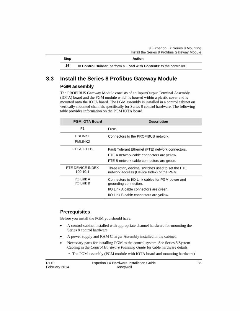
16 In Control Builder, perform a 'Load with Contents' to the controller.
3.3 Install the Series 8 Profibus Gateway Module PGM assembly The PROFIBUS Gateway Module consists of an Input/Output Terminal Assembly (IOTA) board and the PGM module which is housed within a plastic cover and is mounted onto the IOTA board. The PGM assembly is installed in a control cabinet on vertically-mounted channels specifically for Series 8 control hardware. The following table provides information on the PGM IOTA board.
PGM IOTA Board Description
F1 Fuse.
PBLINK1 PMLINK2
Connectors to the PROFIBUS network.
FTEA, FTEB Fault Tolerant Ethernet (FTE) network connectors. FTE A network cable connectors are yellow. FTE B network cable connectors are green.
FTE DEVICE INDEX 100,10,1
Three rotary decimal switches used to set the FTE network address (Device Index) of the PGM.
I/O Link A I/O Link B
Connectors to I/O Link cables for PGM power and grounding connection. I/O Link A cable connectors are green. I/O Link B cable connectors are yellow.
Prerequisites Before you install the PGM you should have:
• A control cabinet installed with appropriate channel hardware for mounting the Series 8 control hardware.
• A power supply and RAM Charger Assembly installed in the cabinet. • Necessary parts for installing PGM to the control system. See Series 8 System
Cabling in the Control Hardware Planning Guide for cable hardware details. – The PGM assembly (PGM module with IOTA board and mounting hardware)

3. Experion LX Series 8 Mounting Install the Series 8 Profibus Gateway Module
36 Experion LX Hardware Installation Guide R110 Honeywell February 2014
– Two PBLink cable assemblies for connecting the slave devices.
• Ensure the cabinet enclosure is connected to a protective earth ground using at least #8 AWG solid copper wire. There should be metal to metal contact between the grounding bus bar and the enclosure as well as the channel.
Install the Series 8 Profibus Gateway Module Procedure Perform the following steps to install a PGM:
Step Action
1 Refer to appropriate site location drawings for the specified installation location, PGM Device Index (FTE address), and wiring diagrams.
2 Identify the mounting location on channel and align mounting holes in IOTA with screw hole locations on the channel.
3 Assemble mounting screws, washers and spacers provided. Insert spacers and washers between backside of IOTA and front of channel. Ensure that the component side of the IOTA is facing up.
4 Position the assembled IOTA board at the proper mounting location.
5 Thread the four mounting screws only half-way to attach the IOTA board to the channel.
6 Tighten the mounting screws securing the IOTA board to the channel.
7 Connect FTE-A and FTE-B Ethernet link cables to the RJ-45 connectors on PGM IOTA board. • The Yellow Cat5 cable connects to the "FTEA" connector on the IOTA. • The Green Cat5 cable connects to the "FTEB" connector on the IOTA.
8 Connect I/O Link cables to the IOTA board. • The cable with green terminal mark connects to the "IOLA" connector on the
IOTA. • The cable with yellow terminal mark connects to the "IOLB" connector on
the IOTA.
9 Connect “PBLink1” and “PBLink2” cables to the IOTA board.

3. Experion LX Series 8 Mounting Install the Series 8 Profibus Gateway Module
R110 Experion LX Hardware Installation Guide 37 February 2014 Honeywell
10 Set the Device Index (FTE DEVICE INDEX) of the PGM according to the site documentation by turning the three rotary decimal switches located on the IOTA board. Set the switches to the three digit address ranging from 001 to 509. The leftmost switch (100) is used to set the hundreds digit. The middle switch (10) is used to set the tens digit and the right-most switch (1) sets the ones digit.
11 Insert the PGM module onto IOTA board making sure that the PGM circuit board is aligned properly with the IOTA board connector. Secure the PGM module to the IOTA board with two screws located at each side of the plastic cover.
PGM IOTA pinouts The following figure illustrates the pinout diagram of the PGM/IOTA DB9-F connector.
DB9-Female
(6) (8)
(1) (3) (5)
1
2
PGM IOTA

3. Experion LX Series 8 Mounting Install the Series 8 I/O Modules
38 Experion LX Hardware Installation Guide R110 Honeywell February 2014
The following table lists the PROFIBUS DB9-F Pin and signal definitions:
Pin Number Signal Description
Shell Shield Shield, Protective Ground
1 Shield Shield, Protective Ground(not recommended-see note)
2 -- Not Connected
3 RxD/TxD-P Receive/Transmit data-plus(B wire, red color)
4 CNTR-P Repeater control signal(direction control), RTS signal
5 DGND Data ground(reference potential for VP)*
6 VP Voltage-plus(P5V), +5V*
7 -- Not Connected
8 RxD/TxD-N Receive/Transmit data-minus(A wire, green color)
9 -- Not Connected
ATTENTION Only the signals shown in the above figure and table are available for PGM. Others are not connected. The metallic shell shall be used as the primary shield and protective ground connection as it provides the best EMI mitigation. Pin 1 is provided for compatibility with older systems that use this pin as a shield connection point. * VP (+5V) and DGND are primarily used for external bus termination. Some devices such as electrical to fiber optic repeaters might require external power from these pins (not to exceed 35 mA). CNTR-P (repeater control) is used in some equipment to determine the direction of transmission/reception.
3. Experion LX Series 8 Mounting Install the Series 8 I/O Modules
R110 Experion LX Hardware Installation Guide 39 February 2014 Honeywell
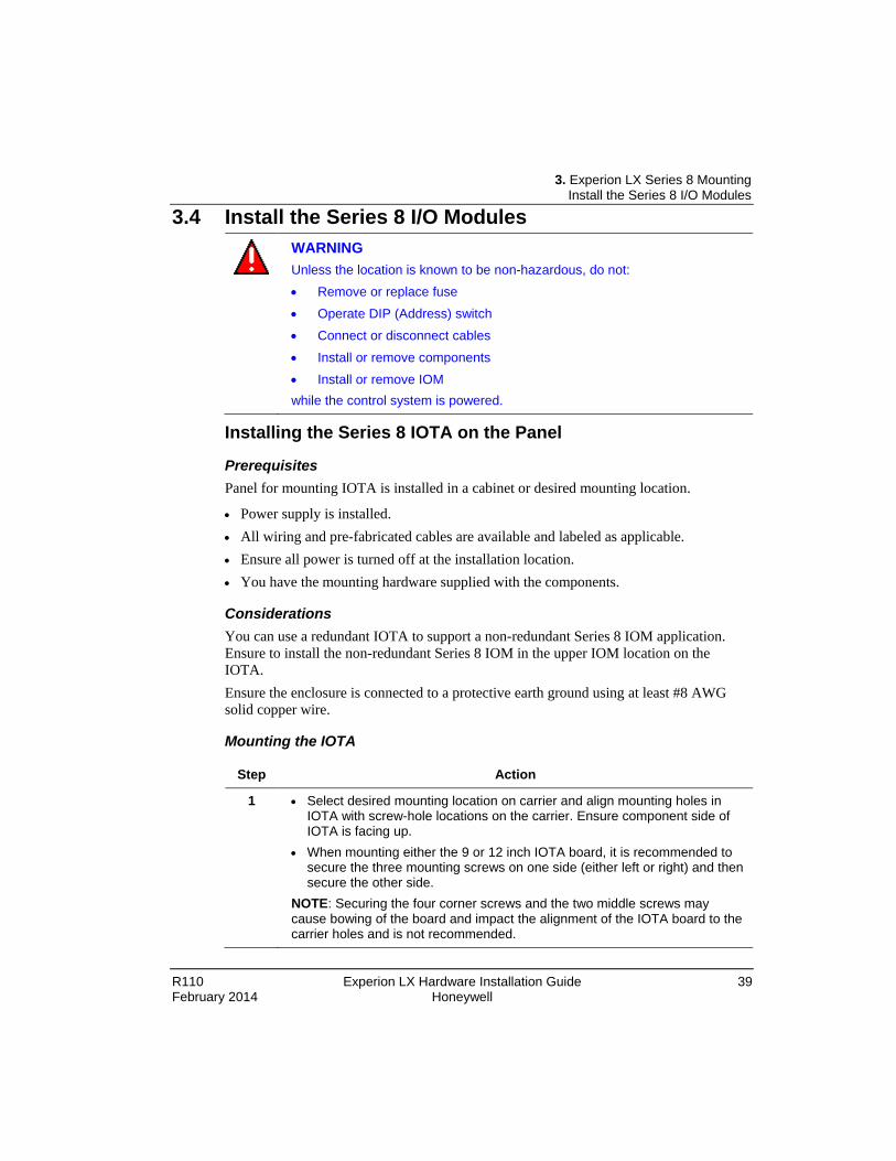
3.4 Install the Series 8 I/O Modules
WARNING Unless the location is known to be non-hazardous, do not: • Remove or replace fuse • Operate DIP (Address) switch • Connect or disconnect cables
• Install or remove components • Install or remove IOM while the control system is powered.
Installing the Series 8 IOTA on the Panel
Prerequisites Panel for mounting IOTA is installed in a cabinet or desired mounting location.
• Power supply is installed. • All wiring and pre-fabricated cables are available and labeled as applicable. • Ensure all power is turned off at the installation location. • You have the mounting hardware supplied with the components.
Considerations You can use a redundant IOTA to support a non-redundant Series 8 IOM application. Ensure to install the non-redundant Series 8 IOM in the upper IOM location on the IOTA. Ensure the enclosure is connected to a protective earth ground using at least #8 AWG solid copper wire.
Mounting the IOTA
Step Action
1 • Select desired mounting location on carrier and align mounting holes in IOTA with screw-hole locations on the carrier. Ensure component side of IOTA is facing up.
• When mounting either the 9 or 12 inch IOTA board, it is recommended to secure the three mounting screws on one side (either left or right) and then secure the other side.
NOTE: Securing the four corner screws and the two middle screws may cause bowing of the board and impact the alignment of the IOTA board to the carrier holes and is not recommended.

3. Experion LX Series 8 Mounting Removal and insertion under power
40 Experion LX Hardware Installation Guide R110 Honeywell February 2014
2
Mounting the I/O module on the IOTA
Prerequisites It is recommended to attach the IOTA board to the carrier prior to mounting the module to the IOTA. The following also needs to be established:
• IOTA is mounted on the carrier rack. • Power supply is installed. • All wiring and pre-fabricated cables are available and labeled as applicable. • Ensure all power is turned off at the installation location. • You have the mounting hardware supplied with the components.
Mounting the module
Step Action
1 Insert the module onto IOTA board ensuring that the circuit board mates properly with the IOTA board connector.
2 Secure the module to the IOTA board - with two screws located at each side of the plastic cover.

3. Experion LX Series 8 Mounting Removal and insertion under power
R110 Experion LX Hardware Installation Guide 41 February 2014 Honeywell
3.5 Removal and insertion under power Many of the Experion LX system's modules (that is, I/O Communications) are designed to permit removal and insertion under power (RIUP) without damaging the module or interrupting backplane communications. However, arching or sparking can occur anytime electrical connections are made or broken. For this reason, removal and insertion must not be performed in hazardous locations when the modules are under power.
WARNING Experion LX's removal and insertion under power (RIUP) feature does not apply to installations that must conform to Division 2/Zone 2, Hazardous Location requirements. Unless the location is known to be non-hazardous, DO NOT do the following: • Connect or disconnect cables; • Connect or disconnect Removable Terminal Blocks (RTBs); • Install or remove modules.
• Remove or replace fuse • Operate DIP (Address) switch
Experion LX communication ports Experion LX has two Ethernet ports, two RS232 ports and two RS485 ports. All of these ports can be used to communicate with SCADA, third-party devices and so on. RS232 ports and Ethernet ports An RJ45 female connector is provided for each of RS232 and Ethernet ports. These ports are identical in both connection and functionality. The connection between RJ45 male and female follows EIA/TIA-561 standard. For RS232 ports, a pre-wired DB9F to RJ45F adapter is included in these units. Use this adapter to make a connection between a serial port on your computer (DB9 male) and RJ45 female on Experion LX.
Figure 3: RJ45 Pin Locations (for RS232 and Ethernet)
RS485 ports RS485 port is also available on all Experion LX units. Experion LX provides two RS485 connections to some specific equipment. It is provided with four terminals: for signal

3. Experion LX Series 8 Mounting Removal and insertion under power
42 Experion LX Hardware Installation Guide R110 Honeywell February 2014
ground, 485+, 485- and termination. Generally, + is connected to + and – is connected to – between units. However, there is no standard for RS485 terminal designations. The situations that + to – or – to + are allowed in some cases. These unconventional operations don’t result in any damages. It is highly recommended that you connect the signal ground to an appreciate ground if available between all RS485 units. Ensure to use a good quality communication cable with three conductors (twisted is preferred) with a shield. To prevent ground loops, the shield must be connected to chassis ground on any one end of any cable connection.
ATTENTION If you have an existing wiring that has only two conductors and a shield, you can use the shield to connect the signal grounds between stations. This is not an optimal (especially for long cable connection) method, but works in most situations.
RS485 Terminals: The Experion LX units have RS485 termination components (150-ohm resistor and a 0.1 µF capacitor connected in series). To terminate the RS485 network, connect the “T” terminal to the RS485 terminal. Ensure to use the same type and size of the conductor as used previously for your RS485 connection. It is recommended that both the end stations connected to your RS485 network be terminated. For third-party devices, refer to their user manual for termination instructions.
ATTENTION Incorrect connections of RS485 will cause communication failure.
Bias Resistors: On a RS485 2-wire network, a pair of bias resistors (1K ohm typically) is required for the transmit/receive wires. The function of bias resistors is to force the transmit/receive wires to a known (non-floating) state when none of the RS485 devices are transmitting data. If the bias resistors are not present, the inputs received on some RS485 devices may react to the noise on the floating wires. Some RS485 devices have bias resistors built-in, and are enabled through DIP-switch or jumper settings. Make sure that there is only one pair of bias resistors acting upon the network.
4. Maintenance For Use in United State (FM Approvals Standards)
R110 Experion LX Hardware Installation Guide 43 February 2014 Honeywell
4. Maintenance If you cannot resolve a problem, you can request support from your local Honeywell Technical Assistance Center (TAC) or support center listed in the “Support and other contacts” section of this document. When requesting support, supply as many relevant details about the problem. When a controller failure occurs, you should gather information about the controller and the conditions under which it failed. This information will be beneficial to Honeywell TAC to help in diagnosing and correcting the fault and/or replacing the controller hardware. Use this list to obtain information from the controller and the system so that when you contact Honeywell TAC a complete description of the problem can be made. • Remove and replace the failed controller. Refer to the section Error! Reference
source not found. for details. • Install the failed controller in a safe off-process location and start it up. Obtain the following: • Hardware revision number of the controller • Firmware revision, both the Boot image and Application image • The RTU System Release number in which the controller was operating. Additional information regarding the operating conditions of the controller and sequence of events: • Was the controller operating in a redundant or non-redundant hardware
configuration? • What was the redundancy state of the controller at the time of the failure, if
redundant? • Any other status or fail indications on the controller's faceplate observed at the time
of the failure or following the event? • Provide a detailed summary of the sequence of events leading up to the failure. • What operations preceded the event, such as: load, activate, change parameter, delete,
power cycle, synchronization, switchover, and so on?

5. Factory Mutual Conditions of Use for Division 2/Zone 2 Hazardous Location Installation For Use in United State (FM Approvals Standards)
44 Experion LX Hardware Installation Guide R110 Honeywell February 2014
5. Factory Mutual Conditions of Use for Division 2/Zone 2 Hazardous Location Installation
5.1 For Use in United State (FM Approvals Standards) • The installer shall provide transient over-voltage protection external to the apparatus
such that the voltage at the supply terminal of the apparatus does not exceed 140% of the voltage rating of the equipment.
• The equipment shall be mounted in an enclosure providing a minimum degree of protection of IP54 in accordance with ANSI/IEC 60529, and in a tool-secured enclosure which meets the requirements of ANSI/ISA 60079-0 and ANSI/ISA 60079-15.
• Equipment shall be installed in compliance with the enclosure, mounting, spacing and segregation requirements of the ultimate application.
Title Number Issue Date
Electrical Equipment for Use in Hazardous (Classified) Locations, General Requirements
3600 2011
Nonincendive Electrical Equipment for Use in Class I and II, Division 2 and Class III, Division 1 and 2, Hazardous (Classified) Locations
3611 2004
Electrical and Electronic Test, Measuring and Process Control Equipment
3810 2005
Electrical apparatus for explosive gas atmospheres. Part 0: General Requirements
ANSI/ISA-60079-0
2013
Explosive atmospheres Part 15: Equipment protected by type of protection “n”
ANSI/ISA-60079-15
2012
5.2 Canadian Standards • The installer shall provide transient over-voltage protection external to the apparatus
such that the voltage at the supply terminal of the apparatus does not exceed 140% of the voltage rating of the equipment.
• The equipment shall be mounted in an enclosure providing a minimum degree of protection of IP54 in accordance with CSA C22.2 No. 60529, and in a tool-secured enclosure which meets the requirements of CAN/CSA 60079-0 and CAN/CSA 60079-15.

5. Factory Mutual Conditions of Use for Division 2/Zone 2 Hazardous Location Installation European Standards
R110 Experion LX Hardware Installation Guide 45 February 2014 Honeywell
• Equipment shall be installed in compliance with the enclosure, mounting, spacing and segregation requirements of the ultimate application.
Title Number Issue Date
Non-incendive Electrical Equipment for use in Hazardous Locations
CAN C22.2 No. 213 - M1987
1987 (2013)
Electrical and Electronic Test, Measuring and Process Control Equipment
C22.2 No. 1010.1
2004
Electrical apparatus for explosive gas atmospheres. Part 0: General Requirements
CAN/CSA E60079-0
2011
Explosive atmospheres Part 15: Equipment protected by type of protection “n”
CAN/CSA E60079-15
2012
5.3 European Standards Title Number Issue
Date LVD directive
Safety requirements for electrical equipment for measurement, control, and laboratory use – Part 1: General requirements
EN 61010-1 2010
EMC directive Electrical equipment for measurement, control and laboratory use - EMC requirements -- Part 1: General requirements
EN 61326-1 2006
Industrial, scientific and medical (ISM) radio-frequency equipment – Electromagnetic disturbance characteristics – Limits and methods of measurement.
CISPR 11: 2009+A1
2010
Electromagnetic compatibility (EMC) – Part 3-2: Limits – Limits for harmonic current emissions (equipment input current ≤ 16A per phase)
IEC 61000-3-2
2009
Electromagnetic compatibility (EMC) – Part 3-3: Limits – Limitation of voltage changes, voltage fluctuations and flicker in public low-voltage supply systems, for equipment with rated current ≤ 16 A per phase and not subject to conditional connection
IEC 61000-3-3
2005

5. Factory Mutual Conditions of Use for Division 2/Zone 2 Hazardous Location Installation European Standards
46 Experion LX Hardware Installation Guide R110 Honeywell February 2014
Electromagnetic compatibility (EMC) – Part 4-2: Testing and measurement techniques – Electrostatic discharge immunity test
IEC 61000-4-2
2008
Electromagnetic compatibility (EMC) – Part 4-3: Testing and measurement techniques – Radiated, radio-frequency, electromagnetic field immunity test
IEC 61000-4-3:2006+A1:2007+A2
2010
Electromagnetic compatibility (EMC) – Part 4-4: Testing and measurement techniques – Electrical fast transient/burst immunity test
IEC 61000-4-4
2004
Electromagnetic compatibility (EMC) – Part 4-5: Testing and measurement techniques – Surge immunity test
IEC 61000-4-5
2005
Electromagnetic compatibility (EMC) – Part 4-6: Testing and measurement techniques – Immunity to conducted disturbances, induced by radio-frequency fields
IEC 61000-4-6
2008
Electromagnetic compatibility (EMC) – Part 4-8: Testing and measurement techniques – Power frequency magnetic field immunity test
IEC 61000-4-8
2009
Electromagnetic compatibility (EMC) – Part 4-11: Testing and measurement techniques – Voltage dips, short interruptions and voltage variations immunity tests
IEC 61000-4-11
2004


Honeywell Process Solutions 1860 W. Rose Garden Lane Phoenix, AZ 85027 USA