Embed Size (px)
Citation preview

2017 Wireless Innovation Forum European Conference on Communication Technologies and Software Defined Radio
1
A. Gotsis, K. Maliatsos, P. Vasileiou, S.Stefanatos
Feron Technologies P.C.
Contact Author: [email protected]
M. Poulakis, A. Alexiou
Department of Digital Systems, University of Piraeus
Contact Author: [email protected]
Abstract1—The current work aims at providing a comprehensive analysis of recent and ongoing activities on enabling device-to-
device communications within traditional LTE radio access networks, as well as proposing a new software library and a software
modem prototype for 3GPP D2D implementation and experimentation. A systematic investigation of the D2D-related 3GPP
specifications is first performed and the key radio protocol implementation aspects are identified and extensively discussed. Focus is on
D2D-specific physical layer processing and radio resource allocation peculiarities. The detailed D2D radio protocol description is
followed by a brief presentation of two relevant software/hardware products developed within the context of EU-funded project
FLEX-D. The first is an open-source software library developed in MATLAB that implements almost all the functionalities of the D2D
radio protocol up to 3GPP release 14, including latest V2X specifications. The second is a real-time standard-compliant software
modem prototype running on general purpose processor hosts and interfacing with SDR boards. Both contributions may aid the R&D
community in understanding the performance limitations of D2D radio protocol and providing the foundations for creating end-to-end
D2D solutions for vertical markets, such as public safety and vehicular communications.
I. INTRODUCTION
Device-to-device communications or simply D2D allow for two user equipment devices (UEs) to communicate directly, hence
allowing single-hop communication instead of the conventional two-hop cellular communication, where the base station is
always the one end of each communication pair. D2D communications is a disruptive paradigm in the cellular world, going
hand-in-hand with LTE evolution and 5G rise in the context of LTE-A, LTE-A Pro, and NR radio technologies [1],[2]. The D2D
system concept within the 3GPP standardization body has both an evolutionary flavor as it benefits the performance of existing
services, by leveraging latency reduction and traffic offloading features, and a revolutionary flavor as it enables new
applications, such as public safety, social networking apps, vehicular communications, and wearables/IoT. The current work has
a two-fold scope: to provide a comprehensive summary of the recent outcomes and ongoing activities around D2D support in
4G/5G, as well as present a D2D protocol software library and a software modem implementation based on the host-SDR model.
In the first part of the paper, we provide a concise technology introduction to the 3GPP D2D radio technology, as it has
evolved from its first appearance in the 3GPP standard Release 12, its minor enhancement in Release 13, its V2X version
planned to appear in the upcoming Release 14, and the application to wearables envisioned for Release 15. In particular, we will
focus on the defined D2D operation modes as well as on the system information/timing reference transmission/acquisition
procedure which is necessary for setting up communication at layer 1 (L1). For each mode, we will present the key D2D radio
technology challenges and aspects, including the related signals, channels and procedures. We will also cover the D2D-specific
radio resources allocation introduced in the standard for managing intra-D2D and inter D2D-LTE operation. The latter is
necessary, since D2D has been decided to operate within the underlying LTE network, specifically reuse part of cellular uplink
(UL) resources. We will also report recent D2D extensions in order to cater for the emerging V2X paradigm.
In the second part of the paper we describe our ongoing activities on developing an open-source software library implementing
the D2D radio protocol standard and a real-time software modem using SDR. First versions of the library have been already
published in Github repository. A first modem prototype is also available, comprising: i) a transceiver implementation of the
basic 3GPP D2D radio functionalities running in general purpose processor (GPP) based hosts; ii) an interface with a USRP
board for over-the-air signal transmission/reception; iii) a basic interface with higher layers for enabling end-user applications.
We describe the software modem architecture along with a detailing of the basic building blocks. The radio transceiver
components development is based on the in-house open software library. We also provide an evaluation of the real-time
capabilities of the prototype modem, based on extensive benchmarking carried out in various typical GPP hosts, and conclude
with a set of over-the-air link-level experiments performend in a EU Future Internet Research Experimentation (FIRE) platform.
The remaining of the paper is structured as follows. Section II provides a tutorial-style introduction to the LTE D2D radio
protocol, while Section III includes a brief overview of our software library implementing the respective transceiver
functionalities. Section IV builds on previous Sections and reports the D2D real-time software modem prototype development
aspects, in particular, the architecture specification, design, implementation, runtime benchmarking and over-the-air link-level
evaluation. Finally, Section IV.E summarizes the key contributions and presents an outlook of the work.
1 The content of this contribution is largely based on material also included in the EU-funded public project deliverable: “FLEX D5.24 (FLEX-D D1), FLEX-
D Innovations & Experimental Activities: Final Report”, which will be shortly available in http://www.flex-project.eu.
Experimenting with Flexible D2D Communications in Current
and Future LTE networks: A D2D Radio Technology Primer &
Software Modem Implementation

2017 Wireless Innovation Forum European Conference on Communication Technologies and Software Defined Radio
2
II. A 3GPP D2D RADIO PRIMER
A. Background – Standardization
The provided material is by no means exhaustive. Instead it covers issues related to intra-D2D and inter D2D/legacy control
signaling (both L1 and higher-layer), as well as D2D L1 processing specifications. These are the fundamental pillars for
designing and implementing a D2D software library as well as a real-time software modem. Issues related to the Core network or
to the end-user application (e.g. security) are beyond the scope of the current paper.
3GPP started considering the support of direct communication among devices in the context of LTE Release 12 [3], [5], under
the code name “ProSe” (proximity services). Although at an initial stage ProSe was centered around public safety use-cases,
soon other commercial services, namely user-oriented (social applications) and network-oriented (offloading) as well as vertical
ones (vehicle-to-vehicle/infrastructure communications) emerged. Initial work conducted within 3GPP resulted in a feasibility
report published in 2013 [6], which highlighted the requirements for introducing communication among proximal UEs under
LTE coverage or in the absence of it (public safety). In the following two years, 2013 and 2014, the D2D radio aspects were
extensively studied in a series of 3GPP RAN1 meetings. A high-level presentation of the envisioned D2D radio architecture,
technologies and protocols, summarizing the main outcomes of the corresponding RAN1 work, was published in [7] and [8], in
2014. The term “sidelink” (SL) has been introduced for explicitly referring to the direct communication link enabled by
D2D (and to differentiate direct-access from typical cellular access), and since then it is considered an integral part of evolving
3GPP releases, together with regular uplink and downlink.
First D2D radio technical specifications (Physical Channels and Modulation, Multiplexing and Channel Coding, MAC,
Physical-Layer Procedures, and RRC) appeared in the 3GPP standards, version 12.5.0 in June 2015. Sidelink defines the
procedures for realizing a single-hop UE-UE communication, similarly to Uplink and Downlink which define the procedures for
UE-BS and BS-UE access respectively. Along the same lines PC5 was introduced as the new direct UE interface, similarly to the
Uu (UE-BS/BS-UE) interface. Sidelink enhancements in Release 13, published in March 2016, focused in network coverage
extension based on L3 relaying provided by a ProSe-enabled UE, the latter supporting both cellular and direct-access
connectivity. In June 2017, Release 14 is expected to be completed, and will include a set of sidelink enhancements for
supporting V2X communications2. Finally, in the context of working Release 15, which is expected to freeze by September
2018, further D2D enhancements related to UE-to-network relays for IoT and wearables, are investigated [9].
B. Radio Protocol Overview
The D2D radio protocol design has been impacted by two important decisions:
Sidelink has been decided to operate in the same resources used for cellular LTE access, and in particular in the
LTE uplink spectrum. In this sense some kind of coordination between sidelink and regular uplink communication
should be employed to avoid harmful interference on any of both sides. Mechanisms for network-controlled D2D access
have been devised, at least when this is possible (i.e. D2D UEs are within full or partial coverage of an LTE eNB).
These are primarily based on L3 signaling (RRC and SIB18/19 configuration messages) and secondarily on L1
signaling (DCI Format 5/5A messages).
Sidelink was decided to operate using new physical signals (synchronization preambles and channel estimation
pilots), control signaling/data physical and transport channels, and MAC channels/structures. Although distinct from
typical cellular-access signals, channels and structures, their design is heavily based on uplink/downlink design.
3GPP has defined two D2D operation modes:
Discovery, where D2D UEs announce their presence to other proximal UEs, sending a very short data message using a
light (in essence L1) protocol stack. The corresponding “inverse” functionalities are also defined, which specify how a
D2D UE could monitor and recover announcements sent by proximal UEs.
Communication, facilitating typical real-time and non-real time applications (e.g. VoIP, on-demand video-streaming,
V2V communication applications), where D2D UEs send/receive data to/from proximal UEs, using a complete protocol
stack, including L1, L2, L3 and above.
A procedure including timing and system-information acquisition is also triggered by both modes. This is necessary for
acquiring L1 synchronization at the receiving D2D UEs’ side as well as inform partial/out-of-coverage D2D UEs about L1
system configuration (bandwidth mode, sidelink physical layer identity, sidelink subframe/frame numbering)3. Towards this
purpose, a protocol for D2D-specific timing synchronization and system information acquisition is also defined. For in-coverage
D2D operation, where both transmitting and receiving UEs reside in the same cell, time synchronization is provided by the
legacy LTE cell and there is no need to perform D2D-specific synchronization. However, there are several scenarios where a
D2D-specific procedure is necessary: (i) in multi-cell in-coverage, where the receiving D2D UE resides in a different
asynchronous cell with respect to the transmitting D2D UE; (ii) in partial-coverage, where the receiving D2D UE is out of
coverage and needs to acquire synchronization from the in-coverage transmitting D2D UE; (iii) out of coverage, where both UEs
are outside the coverage of a legacy LTE cell and the transmitting UE acts as a reference synchronization source.
2 http://www.3gpp.org/news-events/3gpp-news/1798-v2x_r14 3 In this work we implicitly consider timing and system-information acquisition to be a “standalone” mode as well for a baseline D2D link.

2017 Wireless Innovation Forum European Conference on Communication Technologies and Software Defined Radio
3
Sidelink specifications for L1, L2, L3, including the LTE eNB control signaling may be found in the following documents:
36.211 Physical channels and modulation (Section 9)
36.212 Multiplexing and channel coding (Section 5.4)
36.213 Physical layer procedures (Sections 5.2.2.25, 5.2.2.26, 5.10, 14)
36.321 Medium Access Control (MAC) Protocol specification (Sections 5.14, 5.15, 5.16)
36.331 Radio Resource Control (RRC); Protocol specification (Sections 6.5.2, 6.3.8)
C. Radio Protocol Detailed Description
The sidelink physical layer is actually a tweaked version of the conventional LTE UL/DL specifications. Relevant transport
channels, physical channels, control-signaling, and physical signals/sequences are introduced. The structure of the SL processing
(in particular the transmitter side) is illustrated in Figure 1.
Figure 1: 3GPP Sidelink L1 Processing Chain
The main highlights, with emphasis on differentiation aspects from regular uplink/downlink design, are reported in the
following points4:
Timing synchronization and system information acquisition is facilitated by a broadcast transport channel, SL-BCH, and
its physical counterpart, PSBCH. These channels are similar to the BCH/PBCH broadcast channel used in LTE DL for
cell and system acquisition support. They are used for broadcasting a set of pre-ambles and basic system information
within a certain region. A set of primary and secondary preambles, PSSS and SSSS, are used for synchronization
purposes, similar to legacy PSS and SSS sequences. An SL Master Information Block, MIB-SL, similar to the legacy
LTE MIB carries the sidelink system information. Regarding the V2X specifications introduced in Rel.14, slight
modifications are defined for SL-BCH, SSSS and the MIB-SL transmission period.
Sidelink Discovery is facilitated through a transport channel, SL-DCH and its physical counterpart, PSDCH. SL-DCH
follows the Downlink Shared Channel structure. Higher-layer specifications are actually absent in the discovery mode,
since the announcement messages sent by the D2D UEs are PHY Transport Blocks formed with zero MAC overhead.
Filling the TB payload is left open and depends on the ProSe application. For the discovery mode no modifications are
defined for V2X.
Sidelink Communication is facilitated using a transport channel, SL-SCH, and its physical counterpart, PSSCH. These
resemble the DL-SCH and PDSCH channels used for legacy DL data transmission. Data arrives from MAC, which in
turn has arrived from higher layers. Minor modifications are defined for V2X.
In order for the receiving D2D UE to successfully decode the physical communication channels, information regarding
the specific resources assigned for transmission and the transmission configuration is needed. These are carried in a
newly introduced sidelink control channel, called SCI, which resembles the downlink DCI concept. The SCI is carried
4 Specifications for V2V will be finalized in June 2017. Here we present information based on non-frozen versions.

2017 Wireless Innovation Forum European Conference on Communication Technologies and Software Defined Radio
4
in the PSCCH channel, which is similar to the legacy cellular PDCCH/PUCCH channels. For D2D, SCI Format 0 is
introduced, whereas for V2V a new format, SCI Format 1, is defined (from Rel.14 and on).
Physical channels estimation is enabled by the introduction of SL demodulation reference signals (SL-DMRS) which
are highly similar to UL reference sequences. SL-DMRSs are multiplexed with the payload of the PSBCH, PSDCH,
PSCCH, and PSSCH. For D2D, two DMRS symbols per subframe are used for PSBCH, PSDCH, PSCCH, PSSCH. For
V2X, three DMRS symbols are used for PSBCH and four symbols for PSCCH and PSSCH.
Single-layer transmission (no transmit diversity/MIMO) is only allowed, as per the latest Release. For Release 15 and
on, at least transmit diversity will be considered.
All physical channels are modulated following UL SC-FDMA before transmission. The only difference compared to
UL is that the last symbol is zeroed, although taken into account during L1 processing.
Sidelink communication is half-duplex and no feedback channels (e.g. for reporting back channel state information) are
defined.
1) Timing & System Information Acquisition
Timing & system information acquisition is achieved using a special subframe type called broadcast/synchronization (or
simply reference) subframe. Reference subframes are transmitted periodically, i.e. every 40 msec for D2D and 160 msec for
V2V, or at-once, in UL subframes configured by the coordinating LTE eNB5. Transmissions occur at a fixed subframe offset
with respect to the LTE cell subframe timing. The offset is determined through the syncOffsetIndicator L3 parameter, which is
part of the SL-SyncConfig Information Element (IE) transmitted within the SIB18/19. In the standard, reference subframes are
triggered by the discovery and communication modes, hence there is no “standalone” broadcast/synchronization procedure. With
respect to frequency-domain allocation, reference subframes are always loaded at the central 72 subcarriers of the LTE time-
frequency grid, irrespective of the sidelink bandwidth mode. The reference subframe carries two kinds of “information”,
synchronization pre-ambles and system configuration information.
Synchronization preambles: These are constructed based on the physical layer “identity” of the reference UE, 𝑁𝐼𝐷𝑆𝐿. This,
similarly to the Cellular LTE PCI, determines the synchronization pre-amble sequences, PSSS and SSSS, and their mapping to
the time/frequency resources of the subframe [10] (§ 9.7). Through these preambles any proximal D2D UE may acquire time
synchronization with the reference D2D UE and obtain its physical identity. Note that a D2D reference UE is informed about the
sidelink ID through common L3 signaling sent by the legacy network, and in particular by reading out the slssid field which is
part of the SL-SyncConfig IE. The latter IE is transmitted in SIB18 (SIB19) if the reference subframe transmission is triggered by
the communication (discovery) mode.
System information: This is a 40-bit sequence, called MIB-SL, which is passed through transport and physical processing
blocks and mapped to the reference subframe frequency/time resources following [5] §5.4.1 and [4] §9.6. The specific message
structure is shown in Table 1: Table 1: Sidelink Master Information Block (MIB-SL) Structure
sl-Bandwidth
(3 bits)
tdd-ConfigSL
(3 bits)
inCoverage
(1 bit)
reserved
(19 bits)
directFrameNumber
(10 bits)
directSubframeNumber
(4 bits)
where6:
- the sl-Bandwidth field provides the bandwidth mode, set equal to the UL bandwidth mode (1.4, 3, 5, 10, 15, 20 MHz).
𝑁𝑅𝐵𝑆𝐿 expresses accordingly the number of sidelink RBs (6, 15, 25, 50, 75, 100). Note that a UE is informed about the UL
bandwidth through an RRC DL broadcast signaling structure sent by the legacy network, called SIB2, and in particular
through the ul-Bandwidth field.
- the directFrameNumber (DFN) and directSubframeNumber fields support timing reference in the frame and subframe
time-scales respectively. These fields are used if subframe/SFN information from the LTE cell is not available.
- the inCoverage field informs the receiving D2D UEs about the coverage status of the reference D2D UE.
Regarding the base-band time-domain signal generation the cyclic prefix should be also known for applying SC-FDMA. This
is also communicated to the D2D reference UE through SIB18/19, using the syncCP-Len field. This is set as normal or extended,
whereas for V2V only normal cyclic prefix is allowed. To aid PSBCH decoding, a sequence of demodulation reference signals (2
for D2D, 3 for V2V) is generated and mapped across the whole bandwidth of specific SC-FDMA symbols of the reference
subframe following [6] §9.8.
2) Sidelink Discovery
This mode is a “broadcast” like procedure for sending short/light piece of information. Specifically, it enables a D2D UE:
5 In case that the underlying D2D UEs are outside the coverage of an LTE eNB, a pre-defined configuration (stored for example in the SIM
card) may be used. 6 tdd-ConfigSL is irrelevant for FDD

2017 Wireless Innovation Forum European Conference on Communication Technologies and Software Defined Radio
5
to announce its presence to potentially interested proximal UEs through sending a message containing its application
identity or other useful information fields (e.g. GPS coordinates, time, etc.);
to monitor the presence of other proximal UEs by detecting and decoding the corresponding discovery messages, and
under conditions, also respond to them using similar discovery messages.
From a signaling point of view, direct discovery is controlled by the LTE network and in particular by a set of ProSe
functionalities running in the LTE Core Network [11]. These functions provide the interface of the D2D radio with the relevant
D2D applications. In this analysis we do not consider any core-level association procedure (authentication, discovery request and
associated responses), but assume that D2D UEs have been granted access to perform radio-level discovery announcement and
monitoring. Thus, the focus is on the PC5 discovery procedures. The specification of the discovery mode transmission/reception
involves two key functionalities, subframe generation/recovery & resources allocation, both detailed below.
Sidelink discovery subframe generation/recovery:
This includes the transmitter-specific steps, i.e. the preparation of the discovery message transport block, the application of L1
transport and physical channel encoding/processing, the calculation and attachment of DMRSs and the triggering of reference
subframe(s), as well as the “reverse” receiver-specific steps. The discovery subframe carries a PC5 discovery message.
Following [11] § 11.2.5 there are 10 types of PC5 discovery messages, depending on the scope of the procedure. For Open ProSe
discovery, a 232-bit message structured as in Table 2 ([11], Table 11.2.5.1.1), is defined:
Table 2: Structure of Open ProSe Discovery Message (Discovery PHY Transport Block)
Message Type
(4 bits)
ProSe Application Code = PLMN ID (MCC/MNC) + ProSe App ID
(184 bits)
Message Integrity Check
(32 bits)
UTC-based Counter LSB
(8 bits)
where:
- the message type field indicates the discovery type (e.g. open, restricted, etc.) and the content type (e.g. announce,
query, etc.) [11] § 12.2.2.10
- the ProSe application code field [11] § 12.2.2.6 includes the legacy network PLMN identifier (MCC and MNC) as well
as an identifier called ProSe Application ID [11]§ 24.2. The latter is defined during the D2D authentication, is assigned
by the ProSe core functionalities, and is associated with the D2D application triggering D2D discovery.
- the message integrity check (MIC) is used to validate the ProSe application code field setting [11] § 12.2.2.11
- the UTC-based Counter LSB indicates the timing of the discovery transmission opportunity [11] § 12.2.2.22
MAC leaves the discovery message intact (see [15] § 6.1.4) as 3GPP specifies transparent MAC implementation. MAC
forwards this 232-bit sequence (discovery transport block) directly to the PHY for transport processing, following [13] §5.4.4
and physical channel processing, following [10] §9.5. To assist PSDCH decoding at the receiving side, a sequence of
demodulation reference signals is generated and mapped to the discovery D2D subframe following [14]§9.8. Finally, the time-
domain waveform is created using SC-FDMA modulation. The cyclic prefix is configured using L3 signaling, and in particular
through the cp-Len field (set as normal or extended), which is a member of the SL-DiscConfig IE. Observe that the cyclic prefix
of the discovery channel could be set independently from that of the broadcast (and as it will be seen later that of the
communication channel as well).
We conclude by mentioning that when the discovery mode triggers the reference subframe transmission, then the latter will be
transmitted in the subframe(s) indicated by the syncOffsetIndicator L3 parameter as follows: (i) if syncOffsetIndicator indicator
coincides with the first LTE subframe assigned for sidelink discovery transmissions, then the specific subframe will be used; (ii)
otherwise the closest (in-time) subframe indicated by syncOffsetIndicator, which precedes the first LTE subframe assigned for
sidelink discovery transmissions, will be selected.
Sidelink discovery mode resources allocation:
Recall that D2D reuses the legacy UL radio resources, and in this respect if we let D2D UEs to blindly select arbitrary LTE
subframes and PRBs then it is highly possible that uncoordinated interference may corrupt both UL and SL reception.
Coordinated allocation of sidelink resources is realized in two levels: i) in the inter sidelink-uplink level, which is responsible for
the determination of sidelink resource pools to avoid conflict with resources used for regular uplink transmissions; ii) in the
intra-sidelink level, responsible for the determination of UE-specific resources, based on the configured sidelink resource
pool(s). This is used for minimizing/avoiding inter D2D interference. For receiving D2D UEs, multiple resources may be
monitored in order to "listen" for discovery announcements coming from multiple ProSe UEs.
The configuration of the subframe/PRB pools is defined for a certain cell period. The starting subframe and the duration of the
period are defined with respect to cell timing through the following L3 parameters [14] § 14.3.3:
discPeriod, which is allowed to be configured as 32, 64, 128, 256, 512, and 1024 radio frames. The discPeriod field is
included in the SL-DiscResourcePool IE, member of the SL-DiscConfig IE, where the latter is transmitted within the
SIB19 or UE-specific RRCConnectionReconfiguration messages.
offsetIndicator, which is an integer value ranging from 0 to 10239 and indicating the offset of the subframe pool with
respect to SFN #0.
2017 Wireless Innovation Forum European Conference on Communication Technologies and Software Defined Radio
6
Time and Frequency Resource Pools Configuration ([14] § 14.3.3)
Sidelink transmissions only occur on certain subframes, forming a discovery subframe pool, which may carry both sidelink
and uplink control signaling and data, whereas the rest subframes carry only uplink signaling and data. The pool is formed
based on the following L3 parameters (members of SL-DiscResourcePool IEs):
subframeBitmap, a 40-bit (for FDD) binary vector, indicating the sidelink/uplink (‘1’) and the regular uplink (‘0’)
subframe indices, within a 40-subframes length period;
numRepetition, an integer value ranging from 1 to 5, indicating the number of times the subframeBitmap is repeated
within a discovery period.
A sidelink discovery PRB pool contains two equal length subsets of contiguous PRBs. PRB indexing is considered with
respect to PRB #0 of the legacy LTE cell. The subsets are defined based on three numerical L3 parameters (prb-Start , prb-End ,
prb-Num) as follows:
- Subset #1 includes PRBs with indexes greater than or equal to prb-Start and less than prb-Start + prb-Num.
- Subset #2 includes PRBs with indexes greater than prb-End - prb-Num and less than or equal to prb-End.
UE-specific discovery resources allocation ([14] § 14.3.1)
UEs are assigned time and frequency resources for sending/monitoring discovery messages to neighbor UEs from the
respective resources pool. Each unique discovery message is loaded into 2 consecutive PRBs of a single subframe.
Retransmissions of the same PSDCH in different PRB-pair/subframe combinations are also allowed. In particular, by setting the
L3 parameter numRetx appropriately (numRetx range is 0 – 3), up to 4 transmissions per discovery TB, thus in total 5
transmissions, are supported.
There are two types of UE-specific resource allocation:
- Type 2B or “Scheduled”, which is centrally configured for all D2D UEs at the LTE eNB.
- Type 1 or “UE-selected”, which allows UEs to autonomously select the resources;
For both resource allocation types, the objective is to avoid, as much as possible, the assignment of common time/frequency
resources to different discovery TBs.
For the “Scheduled” type, conflicts may be fully prevented, as the eNB is fully responsible for the allocation decisions. Given
a discovery subframe/PRB pool, the starting indices of the time and frequency resources within the pool are determined through
L3 parameters discSF-Index an discPRB-Index respectively. In case hopping resource allocation is applied, three additional L3
parameters must be configured, 𝑎, 𝑏, and 𝑐, in order to determine the exact hopping pattern. All these parameters are part of the
SL-DiscConfig IE.
For the “UE-selected” resource allocation type, UEs select autonomously the exact time and frequency resources from the
pool. This is done using a randomization pattern based on a MAC configuration parameter called “resource index” (𝑛𝑃𝑆𝐷𝐶𝐻),
from which the actual subframe and PRB indexes (within the pool) for carrying the discovery message are extracted. Different
UEs should select different 𝑛𝑃𝑆𝐷𝐶𝐻 to avoid interference. Although there is no guarantee that resource allocation conflicts are
avoided, the random nature of the resource index provides an acceptable level of protection. At the receiver side, a UE may
“blindly” monitor for multiple discovery messages by investigating resources corresponding to different 𝑛𝑃𝑆𝐷𝐶𝐻 settings.
We provide a simple numerical example for clarifying the interpretation of the resource index configuration: Assume a
subframe pool containing 40 subframes and 16 PRBs, and that numRetx = 1, i.e. 2 transmissions per discovery TB are
configured. Given that each unique TB transmission occupies a single subframe and two PRBs, then there are 𝑁𝑡 = 40 2⁄ = 20
unique time resources and 𝑁𝑓 = 16 2⁄ = 8 unique frequency resources. Thus, in total there are 𝑁𝑡 ∙ 𝑁𝑡 = 160 non-conflicting
UE-specific resources. Any resource index value 𝑛𝑃𝑆𝐷𝐶𝐻 selected from 0 to 159 will lead to disjoint resource assignments. The
mapping of each resource index to the specific subframe/PRB-pair combination is done based on the formulas given in [14] §
14.3.1
3) Sidelink Communication
The sidelink communication mode was initially introduced in 3GPP D2D within the context of public safety applications (e.g.
VoIP, MCPTT). Commercial D2D communication services are also envisaged for LTE Evolution and 5G. Special attention has
been paid to V2X applications, starting from Release 14. Similar to the discovery mode, resource allocation configuration is
based on the concept of sidelink pools for mode-specific allocation and centralized/autonomous decisions for UE-specific
allocation. L1 processing and subframe generation on the other hand resembles the approach followed for the LTE downlink. In
particular, each transmission involves: i) a “control” part, which is used for informing the receiving UEs about the exact
resources used for carrying the data as well as the transmission configuration (PRB allocation, modulation and coding scheme,
re-transmission opportunity) which should be known at the receiver for data recovery; ii) a “data” part which is used to carry the
payload bits. In the standard, D2D communication is distinguished from V2X using a parameter called sidelink transmission
mode. Modes 1 and 2 refer to D2D while modes 3 and 4 to V2X.

2017 Wireless Innovation Forum European Conference on Communication Technologies and Software Defined Radio
7
Sidelink Communication control & data subframe generation/recovery
Control Channel for D2D Communication
Control information is expressed in the form of SCI messages, which are similar to DL control messages, known as DCI. SCI
Format 0 was introduced in Rel.12 ([15] §5.4.3.1.1) for D2D communications. SCI-0 contains 37 – 45 bits, depending on the SL
bandwidth mode. The SCI fields are populated as follows:
- for sidelink transmission mode 1 (“fully controlled” mode) using higher layer information carried by L3 control
signalling, i.e. RRC, and L1 control signalling configured at the eNB as DCI messages, in particular DCI Format 5 ([15]
§5.3.3.1.9),
- for sidelink transmission mode 2 (“autonomous” mode) based on autonomous decisions taken by each transmitting UE.
The structure of SCI Format 0 and DCI Format 5 messages are given in Table 3 and Table 4 respectively.
Table 3: Sidelink Control Information Format 0 (Standard D2D) Message Structure
Frequency
Hopping flag
(1 bit)
Resource block assignment and
hopping resource allocation
(5,7,9,11,12,13 bits)
Time Resource Pattern (7 bits)
Modulation and coding scheme (5 bits)
Timing advance indication (11 bits)
Group Destination ID (8 bits)
Table 4: Downlink Control Information Format 5 (DCI Format 5) Message Structure
Resource for PSSCH
(6 bits)
TPC for PSCCH,
PSSCH (1 bits)
Frequency
Hopping flag (1 bit)
Resource block assignment and hopping
resource allocation (5 – 13 bits)
Time Resource Pattern
(7 bits)
SCI Format 0 message is constructed as follows:
- Frequency hopping flag and Resource block assignment and hopping resource allocation fields provide the necessary
information for the receiving UEs to identify the PRBs where the data channel (PSSCH) resides. Sidelink PRB resource
allocation is based on the principles of uplink resource allocation. For the non-hopping case only type-0 is supported,
and for hopping both type 1 and type 2 (implicit and explicit hopping pattern definition) [14] § 8.1, § 8.4. For sidelink
transmission mode 1 both fields are defined in the DCI 5 message and are just copied to SCI. For mode 2 the fields are
configured autonomously by the transmitting D2D UE. For both modes, the selected PRBs should belong to the sidelink
communication PRB pool.
- Time resource pattern (TRP) provides the time-domain resource allocation for the data channel (PSSCH), and in
particular the potential subframes used for PSSCH transmission. In particular, a TRP indicator ranging from 0 to 127,
determines a repeated PSSCH subframe pattern, where the subframe mapping process is defined as follows: i) for mode
1 through [14] Tables 14.1.1.1.1-1, where the indicator is copied from the corresponding DCI field ; ii) for mode 2
through [14] § 14.1.1.3 with the help of the L3 parameter trpt-Subset, which is transmitted as part of the
CommResourcePool IE.
- Modulation and coding scheme, provides the MCS used for PSSCH. Regarding modulation, QPSK and 16-QAM are
supported. For mode 1 the MCS is configured by L3 through the mcs field, part of the SL-CommConfig IE. For mode 2
it is selected autonomously by the UE.
- Timing advance indication, provides a recent uplink-downlink time adjustment value as per [14] § 14.2.1 for mode 1 or
set to 0 for mode 2.
- Group ID (𝑛𝐼𝐷𝑆𝐴) is an 8-bit code provided by higher layers, indicating the group of UEs which are potentially interested
for the transmitted message. This is used at the receiving side for ignoring messages destined to other groups.
The generated SCI message undergoes transport channel encoding following [13] § 5.4.3, and then the generated block is split
into two parts, each of which undergoes physical channel encoding following [14] § 9.4. The generated PSCCHs are loaded
into a single PRB of two distinct subframes, together with DMRS sequences as of [14] § 9.8. Hence, each control message
spans two PRB/subframe resource units. Notice that this is different from downlink control signaling, where a PDCCH is
loaded into a single subframe. At the receiver side the UE should combine both resource units (subframe/PRB pairs) to recover
the control signaling information, and thus extract the data channel allocation and transmission configuration.
Control Channel for V2X Communication
A new SCI type, SCI Format 1, has been introduced in Rel.14 to cater for V2X control channel configuration transmission
[15] §5.4.3.1.2. As in D2D, a new DCI message type, DCI Format 5A, has been also introduced for carrying eNB control
information [15] §5.3.3.1.9A. The structure of SCI Format 1 and DCI Format 5A messages are given in Table 5 and Table 6
respectively. Table 5: Sidelink Control Information Format 1 (V2V) Message Structure
Priority
(3 bits)
Resource
Reservation (4 bits)
Frequency Resource
Location (0,3,6,7,8 bits)
Time Gap
(4 bits)
Modulation and
Coding Scheme (5 bits)
Retransmission
Index (1 bits)
Reserved
Bits (15,12,9,8,7 bits)
2017 Wireless Innovation Forum European Conference on Communication Technologies and Software Defined Radio
8
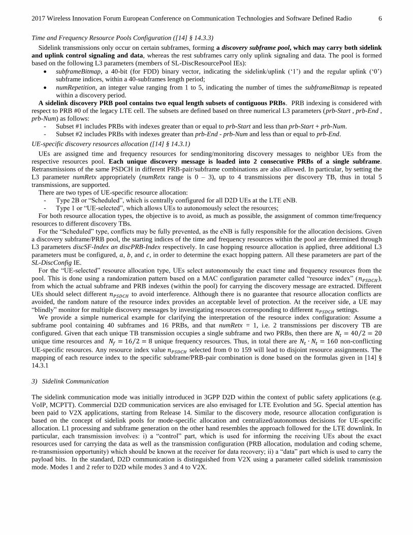
Table 6: Downlink Control Information Format 5A (DCI Format 5A – V2V) Message Structure
Carrier Indicator (3 bits)
Lowest Index of the Subchannel allocation (0,2,3,4,5 bits)
Frequency Resource Location (0,3,6,7,8 bits)
Time Gap (4 bits)
SCI Format 1 message is constructed as follows:
- Priority, includes one of 8 possible values, corresponding to the ProSe Per-Packet Priority (PPPP) configured by the
ProSe application-layer and used for QoS purposes ([16], § 5.4.6);
- Resource Reservation, is a field used only in the autonomous V2X mode (mode-4), for announcing resources to be used
based on sensing decisions ([14] § 14.2.1).
- Frequency Resource Location, is a bit pattern used to define PSSCH PRB resources ([14] § 14.1.1.4C);
- Time Gap, is the subframe gap between the first and (optional) second PSSCH transmission (re-transmission) ([14] §
14.1.1.4C).
- Modulation and Coding Scheme, determines the MCS used for PSSCH;
- Retransmission Index, is a boolean field, denoting if the corresponding PSSCH refers to the first transmission or the
(optional) second transmission, i.e. the re-transmission ([14] § 14.1.1.4C).
- Reserved bits, are dummy zero bits, added for assuring that the SCI message size is 32 bits.
The generated SCI message undergoes transport channel encoding following [13] § 5.4.3, as in the D2D control channel case,
with a slight difference in the sequence used for PUSCH interleaving. An identifier notated as 𝑛𝐼𝐷𝑋 which corresponds to the SCI
CRC checksum is also generated; this is going to be used in data encoding (PSSCH). The encoded block then undergoes physical
channel encoding following [14] § 9.4, as in the D2D control channel case. The PSCCH is loaded (together with DMRSs) in
two consecutive PRBs of a single subframe, differently from the D2D control channel case, where a single PRB and two
subframes are used. In case a retransmission is configured, the same PSCCH content is loaded into another subframe/PRB-pair
from the pool.
Data Channel for D2D Communication
Differently from broadcast, discovery and communication control channel, where the transport block size is fixed, in the
sidelink communication data channel, the size is not pre-determined. Instead it is dynamically formed, based on the number of
assigned PRBs and the configured MCS. Following the mapping methodology in [14], and specifically Table 8.6.1-1, the SL-
SCH transport block size is first calculated and then filled with bits from higher layers. The transport block then undergoes
transport channel encoding following [13] § 5.4.2. The generated block is then split into 4 parts, and each part undergoes
physical channel processing according to [10] § 9.3. Each PSSCH, along with relevant DMRSs ([10] § 9.8) is loaded into
distinct subframes/PRB subsets, belonging to the sidelink communication pool. At the receiver side all 4 PSSCHs should be
combined to recover the data transport block.
Data Channel for V2X Communication
As in the D2D communication, the transport block size is initially determined based on the assigned PRB bandwidth and the
MCS configuration. The transport block undergoes transport channel encoding following [13] § 5.4.2. The only difference
compared to D2D communication is the scrambling sequence definition; in D2D it is based on the group id (𝑛𝐼𝐷𝑆𝐴) , whereas for
V2X on the parameter 𝑛𝐼𝐷𝑋 , calculated during the SCI transport channel encoding. Then, the encoded block undergoes physical
channel processing as in [10] § 9.3 and loaded into a single subframe and a subset of sidelink pool PRBs. If re-transmission
is configured in PSCCH, another subframe transmits an identical PSSCH.
Sidelink Communication Mode Resource Allocation
Sidelink communication mode resources allocation follows the same principles applied for the discovery mode. First, mode-
specific time and frequency resource pools are formed, and at a second stage D2D UEs are allocated specific resources for
control and data from these pools.
Time and frequency resource pools configuration for D2D communication [14] § 14.2.3, 14.1.3, 14.1.4
The configuration of the subframe/PRB pools is defined for a certain cell period. The starting subframe and the duration of the
period are defined with respect to cell timing through the following L3 parameters:
offsetIndicator, which is an integer value with range 0 to 319, indicating the offset of the subframe pool with respect to
SFN #0.
sc-Period, which is allowed to be configured as 40, 80, 160, 320 subframes. The sc-Period field is included in the SL-
CommResourcePool IE, transmitted within the SIB18 or the RRCConnectionReconfiguration messages.
PSCCH and PSSCH subframe pools are constructed based on L3 parameter, subframeBitmap, which defines a 40-bit length
pattern for uplink/sidelink resources distribution. PSCCH and PSSCH pools are separated. Therefore, a UEs’ control and data
may not be multiplexed in the same subframe. The PSCCH pool precedes. For transmission mode 1 the PSSCH pool starts
exactly after the end of the PSCCH pool, whereas for mode 2 it starts at a fixed time-offset with respect to the PSCCH pool.

2017 Wireless Innovation Forum European Conference on Communication Technologies and Software Defined Radio
9
The PRB pool is defined exactly as in the discovery mode case, using three L3 parameters, prb-Start, prb-End, prb-Num,
which are part of an IE dedicated to the communication mode configuration (SL-CommConfig IE). A common PRB pool for
PSCCH and PSSCH is defined (since control and data are loaded in different subframes anyway).
UE-specific resources allocation for D2D communication [14] § 14.1.1.1, 14.1.1.2, 14.2.1.1, 14.2.1.2:
For the control channel (PSCCH) a set of two subframe/PRB pairs belonging to the PSCCH resource pool is
determined based on a randomization resource index parameter, 𝑛𝑃𝑆𝐶𝐶𝐻. This allows to define non-conflicting resource
assignments using a single scalar. For mode 1, the transmitting UE is informed about this value from the eNB, in particular
through the DCI Format 5 message. For mode 2 the resource index is configured autonomously by the transmitting UE. The
receiving UE could look at resources corresponding to specific 𝑛𝑃𝑆𝐶𝐶𝐻s or blindly search in a 𝑛𝑃𝑆𝐶𝐶𝐻-specific range.
For the data channel (PSSCH), a set of four subframes from the PSSCH pool is picked, based on a UE-specific subframe
bitmap, 𝐼𝑇𝑅𝑃, which indicates the subframe indices within the pool. The standard defines 108 available patterns ([14] Table
14.1.1.1.1-1). A scalar parameter, TRP, is used to indicate the UE-specific pattern. TRP is carried in the DCI Format 5 message
for mode-1 or autonomously selected by the UE in mode-2, using an additional higher layer parameter, trpt-subset. For both
modes, the TRP field is also copied at the SCI Format 0 message, in order for the receiving D2D UE to know where to look for
PSSCH data. The PRBs used for the PSSCH are determined based on the Frequency hopping flag and Resource block
assignment and hopping resource allocation fields (carried in DCI-5 and again copied in SCI-0) for mode-1 or determined
autonomously for mode-2.
Time and frequency resource pools configuration for V2X communication [14] § 14.2.4, 14.1.5:
Configuration of time and frequency pools is not employed on a period basis as in the sidelink discovery and standard
communication modes. Instead it applies over the whole SFN cycle ([14] § 14.1.5), where an L3-defined pattern,
subframeBitmap-r147, together with a set of excluded subframes (used for synchronization, downlink or other special purposes),
determine the available subframes. The specific bitmap length is 10-100, and is repeated over the SFN cycle. A subframe offset
indicator parameter, offsetIndicator-r14, indicates the 1st available V2X subframe. Frequency-domain resources are organized as
follows:
- PRBs are grouped in subchannels.
- The subchannel size is determined by the L3 parameter sizeSubchannel-r14, part of SL-CommResourcePool IE. For up
to 5 MHz bandwidth mode, the following subchannel sizes are allowed: 4, 5, 6, 8, 9, 10, 12, 15, 16, 18, 20.
- The number of subchannels allocated to a V2X PSCCH/PSSCH resource pool is determined by another L3 parameter,
numSubchannel-r14, which may be configured as 1, 3, 5, 10, 15, 20.
- The pool contains a contiguous set of PRBs. The lowest PRB index of the subchannel with the lowest index is given by
the L3 parameter, startRB-Subchannel8.
- PSCCH and PSSCH PRB pools may be adjacent or not. This is determined by the L3 boolean parameter
adjacencyPSCCH-PSSCH-r14. For the adjacent mode, PSCCH and PSSCH PRB pools are identical, otherwise the
PSCCH pool starting PRB index is given by the L3 parameter startRB-PSCCH-Pool-r14.
UE-specific resources allocation for V2X communication [14] § 14.1.1.4A, 14.1.1.4B, 14.1.1.4C, 14.2.1
Each transmission opportunity for the control channel, i.e. the regular transmission and the optional re-transmission,
occupies a single subframe and two PRBs. The DCI Format 5A field 𝑆𝐹𝑔𝑎𝑝 determines the time-offset (in # subframes) for the
two transmission opportunities. Regarding the PRB pair: i) for the adjacent mode, the first two PRBs of the PSSCH/PSCCH UE-
specific PRB subsets are used; ii) for the non-adjacent mode, two PRBs from the dedicated PSSCH pool, starting from PRB
index given by L3 parameter, nsubCHstart, are used.
For the data channel (PSSCH), exactly the same subframes assigned for PSCCH are used. The PRB set assigned to each UE is
based on the parameters nsubCHstart (lowest index of allocated subchannel) and LsubCH (number of allocated subchannels),
which are derived from the Frequency Resource Location field of the DCI Format 5A message (and copied to SCI Format 1
messages in order for the receiver to recover the correct resources). For the adjacent PSCCH-PSSCH mode, care is taken such
that the first two PRBs of the lowest index subchannel are not allocated for PSSCH, since these are used for PSCCH.
Consequently, control and data for a specific V2X communication transmission are located in the same time resource and
potentially in adjacent frequency resources, which is not the case for standard D2D.
We conclude the current Section with Table 7, which summarizes the physical signals, physical channels and transport
channels relevant to sidelink for both D2D and V2X modes.
7 r14 is added to distinguish it from the corresponding bitmap parameter defined for standard D2D communication. 8 An example configuration is as follows: Assume sizeSubchannel-r14 = 4, numSubchannel-r14 = 3, and startRB-Subchannel = 2, then the
PRB pool contains i) Subchannel #0, including PRBs #2,3,4,5; ii) Subchannel #1, including PRBs #6,7,8,9 and iii) Subchannel #3, including
PRBs #10,11,12,13.

2017 Wireless Innovation Forum European Conference on Communication Technologies and Software Defined Radio
10
Table 7: Transport, Signalling, Physical Channel, and Physical Signals for Sidelink D2D/V2X
OPERATION MODE Discovery Communication Timing & System Information Acquisition
PHY Transport Block
Size/Message 232-bits (arriving from application)
L1 signalling (37-45 bits, D2D; 32 bits,
V2X)
Variable size (arriving from L2)
40-bits MIB-SL
Transport/Signalling Channel Processing
Transport/Signalling Channel
SL-DCH
SCI Format 0 (D2D)
Format 1 (V2V)
SL-SCH SL-BCH
Segmentation & CRC attachment
DL-SCH - DL-SCH -
TB CRC attachment gCRC24A gCRC16 (no scrambling)
gCRC24A gCRC16
Channel Coding TC CC TC CC
Rate Matching TC CC TC CC
Interleaving (𝑐𝑚𝑢𝑥) 2 ∙ (𝑁𝑆𝐿𝑠𝑦𝑚𝑏
− 1)
2 ∙ (𝑁𝑆𝐿𝑠𝑦𝑚𝑏
− 1), D2D
2 ∙ (𝑁𝑆𝐿𝑠𝑦𝑚𝑏
− 2),V2X
2 ∙ (𝑁𝑆𝐿𝑠𝑦𝑚𝑏
− 3), D2D
2 ∙ (𝑁𝑆𝐿𝑠𝑦𝑚𝑏
− 2) − 3, V2X
2 ∙ (𝑁𝑆𝐿𝑠𝑦𝑚𝑏
− 3), D2D
2 ∙ (𝑁𝑆𝐿𝑠𝑦𝑚𝑏
− 2) − 3,
V2X
Physical Channel & Signals Processing
Physical Channel PSDCH PSCCH PSSCH PSBCH
Scrambling (𝑐𝑖𝑛𝑖𝑡)
510 510 𝑛𝐼𝐷𝑆𝐴(𝑛𝐼𝐷
𝑋 ) ∙ 214 + 𝑛𝑠𝑠𝑓𝑃𝑆𝑆𝐶𝐻 ∙
29 + 510, D2D(V2V)
𝑁𝐼𝐷𝑆𝐿
Modulation QPSK QPSK QPSK, 16QAM QPSK
Layer Mapping/ Precoding
Single-Layer, Single Antenna (no MIMO or Tx Diversity)
Transform Precoding As in uplink
Demodulation Reference Signals
Group hopping disabled disabled disabled
Reference Signal
Identifier (𝑛𝐼𝐷𝑅𝑆)
- 𝑛𝐼𝐷𝑋 𝑛𝐼𝐷
𝑆𝐴 -
Slot Index (𝑛𝑠) - -
𝑛𝑠𝑠𝑃𝑆𝑆𝐶𝐻, D2D
2 ∙ 𝑛𝑠𝑠𝑃𝑆𝑆𝐶𝐻 (slot 0),
2 ∙ 𝑛𝑠𝑠𝑃𝑆𝑆𝐶𝐻 + 1 (slot 1), V2V
-
Sequence-shift pattern (𝑓𝑠𝑠)
0 0 for D2D, 8 for
V2V
𝑛𝐼𝐷𝑆𝐴𝑚𝑜𝑑30, D2D
⌊𝑛𝐼𝐷𝑋 /16⌋𝑚𝑜𝑑30, V2V
⌊𝑁𝐼𝐷𝑆𝐿/16⌋𝑚𝑜𝑑30
Sequence hopping disabled disabled disabled disabled
Cyclic shift (𝑛𝐶𝑆,𝜆)
0 0 for D2D,
{0,3,6,9} for V2V
⌊𝑛𝐼𝐷𝑆𝐴/2⌋𝑚𝑜𝑑8, D2D
⌊𝑛𝐼𝐷𝑋 /2⌋𝑚𝑜𝑑8, V2V
⌊𝑁𝐼𝐷𝑆𝐿/2⌋𝑚𝑜𝑑8
Orthogonal sequence
[𝑤𝜆(0) 𝑤𝜆(1)] [+1 + 1]
[+1 + 1], D2D [+1 + 1 + 1 + 1],
V2V
D2D: [+1 + 1] 𝑖𝑓𝑛𝐼𝐷
𝑆𝐴 𝑚𝑜𝑑2 = 0
[+1 − 1] 𝑖𝑓𝑛𝐼𝐷𝑆𝐴 𝑚𝑜𝑑2 = 1
V2V: [+1 + 1 + 1+ 1] 𝑖𝑓𝑛𝐼𝐷
𝑋 𝑚𝑜𝑑2 = 0 [+1 − 1 + 1− 1] 𝑖𝑓𝑛𝐼𝐷
𝑋 𝑚𝑜𝑑2 = 1
[+1 + 1] 𝑖𝑓𝑁𝐼𝐷𝑆𝐿 𝑚𝑜𝑑2
= 0
[+1 − 1] 𝑖𝑓𝑁𝐼𝐷𝑆𝐿 𝑚𝑜𝑑2
= 1
Synchronization Signals
PSSS 𝑢 = 26, 𝑖𝑓 𝑁𝐼𝐷𝑆𝐿 ≤ 167, 𝑒𝑙𝑠𝑒 𝑢 = 37 @ slot 0 symbols #1,#2 (normal cp), #0,#1 (ext. cp)
SSSS 𝑁𝐼𝐷(1)
= 𝑁𝐼𝐷𝑆𝐿𝑚𝑜𝑑168, 𝑁𝐼𝐷
(2)= ⌊𝑁𝐼𝐷
𝑆𝐿/168⌋ @ slot 1 symbols #4,#5 (normal cp), #3,#4 (ext. cp)

2017 Wireless Innovation Forum European Conference on Communication Technologies and Software Defined Radio
11
III. AN OPEN SOFTWARE LIBRARY FOR IMPLEMENTING THE 3GPP D2D RADIO PROTOCOL
A. Scope – Features
lte-sidelink is a software library developed in MATLAB, that implements the most important functionalities of the 3GPP LTE
sidelink interface9. It is freely and openly available through the following public online repository: https://github.com/feron-
tech/lte-sidelink. The project is licensed under the GNU Affero General Public License v3.0. The library provides an (almost)
complete implementation of the sidelink physical signals, physical channels and transport layer functionalities described in the
3GPP standard. In addition, it provides the necessary transceiver processing functionalities for generating and/or recovering a
real sidelink signal for simulation/emulation purposes and/or over-the-air experiments using SDR boards. The code is highly-
modular and documented in order to be easily understood and further extended. The library has many usages. For example, it
may be used as:
An LTE sidelink waveform generator.
An end-to-end sidelink link-level simulator.
A core component of a sidelink system-level simulator.
A platform for testing new resource allocation/scheduling algorithms for D2D/V2V communications.
A tool to experiment with live standard-compliant sidelink signals with the help of SDR boards.
The following features are currently (as of v1.2.0) supported:
Sidelink air-interface compliant with:
o "Standard" D2D based on Rel.12 and Rel.13
o D2D tweaks for V2V communications based on Rel.14
Broadcast transport & physical channel processing functionalities
o Generation and recovery of MIB-SL messages
o Encoding and recovery of the SL-BCH transport channel
o Encoding and recovery of the PSBCH physical channel
o Demodulation Reference Signals (DMRS) construction and subframe loading
Sidelink discovery mode
o Physical Signals and Channels: SL-DCH, PSDCH, PSDCH DMRS
o Subframe/PRB discovery pool formation & UE-specific resource allocation
Sidelink communication mode
o Physical Signals and Channels for Control Signaling: SCI Format 0, PSCCH, PSCCH DMRS
o Physical Signals and Channels for Payload: SL-SCH, PSSCH, PSSCH DMRS
o Subframe/PRB communication pool formation & UE-specific resource allocation for control/data
V2X sidelink communication mode
o Physical Signals and Channels for L1 signaling: SCI Format 1 (V2V), PSCCH, PSCCH DMRS
o Physical Signals and Channels for Payload: V2X PSSCH, PSSCH DMRS
o Subframe/PRB pool formation & UE-specific resource allocation for V2X communication for control/data
Synchronization preambles (PSSS, SSSS) construction & recovery
Subframe creation, loading and time-domain signal transformation
Complete receiver processing functionality for sidelink-compliant waveforms
o time-synchronization
o frequency-offset estimation and compensation
o channel estimation and equalization
o signal demodulation/decoding
Example scripts for configuring and running end-to-end broadcast, discovery, and D2D/V2X communication
transceiver simulation scenarios.
The code repository is structured as follows:
The home directory includes the example scripts for testing sidelink functionality.
The core directory includes the sidelink-specific functionalities implementations, i.e. the physical/transport channels,
the DMRSs, synchronization signals, channel estimation procedures, organized in classes.
The generic directory includes generic (non-sidelink specific) tx/rx functionalities implementations, organized in
functions, i.e. signal, physical and transport channel blocks, necessary for core classes implementation.
9 The majority of the content used in the current Subsection is also available in the project online repository, https://github.com/feron-
tech/lte-sidelink/blob/master/README.md (in “readme” format) or in https://feron-tech.github.io/lte-sidelink/ (in “web-site-friendly” format).
Refer to any of these links for software and documentation updates.

2017 Wireless Innovation Forum European Conference on Communication Technologies and Software Defined Radio
12
A list of library dependencies/known issues is also reported:
All functionalities are developed in-house except for: i) CRC encoding/detection, ii) Convolutional Encoding/Decoding.
For these, the corresponding MATLAB Communication Toolbox System Objects have been used. In-house versions of
these two blocks will be also provided soon.
Convolution channel coding has been applied for sidelink discovery and communication modes transport channel
processing, instead of standard-compliant turbo coding.
The last subframe symbol in SC-FDMA modulation is not zeroed as specified in the standard.
V2X communications support is added but not fully tested.
Testing of the code has been done in MATLAB R2016b.
Next, based on the provided library, we develop an end-to-end transceiver simulation example for the sidelink discovery
mode, including the complete L1 processing and resources allocation procedures, following the respective specifications.
B. An Example Usage: End-to-End Sidelink Discovery Mode Simulation
The sidelink discovery mode is used for sending (in a broadcast way) short messages to neighbor UEs. The sidelink discovery
transmission/reception procedure involves two key functionalities:
Selection of time (subframes) and frequency (PRBs) resources for sending/monitoring discovery messages.
L1 processing, i.e. signal generation (for tx) and transport block recovery (for rx) operations.
Next, we provide a high-level walkthrough for setting up, configuring, and running a complete transceiver simulation scenario
for the sidelink discovery mode (refer to library file sidelink_discovery_tester.m).
1) Configuration
The available parameters may be organized in three subsets:
A basic configuration set, providing the key operational system parametrization. It includes the cyclic prefix length
(cp_Len_r12), sidelink bandwidth mode (NSLRB), sidelink physical layer id (NSLID), sidelink transmission mode
(slMode), synchronization offset with respect to SFN/DFN #0 (syncOffsetIndicator), and synchronization period
(syncPeriod), for both discovery and triggered broadcast/synchronization subframes.
Discovery Resources Pool configuration, providing the sidelink resources allocation parametrization. The available
parameters are briefly described in the following bullet points, while the interested reader could refer to the 3GPP
standard 36.331, Section 6.3.8, for more details:
o discPeriod_r12: the period (in # frames) for which the resource allocation configuration is valid (available
configurations: 32,64,128,256,512,1024 frames)
o offsetIndicator_r12: the subframe offset (with respect to SFN/DFN #0) determining the start of the
discovery period.
o subframeBitmap_r12: a length-40 bitmap determining the time (subframe) pattern used for sidelink
transmissions (‘1’s determine the subframes available for sidelink transmissions)
o numRepetition_r12: the repeating pattern of the subframe bitmap (available configurations: 1-5)
o prb_Start_r12: the first PRB index of the bottom PRB pool available for discovery transmissions
o prb_End_r12: the last PRB index of the top PRB pool available for discovery transmissions
o prb_Num_r12: the number of PRBs assigned to top/bottom PRB pools for discovery transmissions
o numRetx_r12: the number each discovery message is re-transmitted (available configurations: 0-3)
o networkControlledSyncTx: determines if broadcast/sync subframes should be triggered (1 for triggering, 0
for no-triggering)
o syncTxPeriodic: determines if the triggered broadcast/sync subframes are transmitted at once ("single-shot")
or periodically (every 40 subframes)
o discType: determines how sidelink resources are allocated to the different discovery transmissions, i.e.
selected by each UE in an autonomous manner (Type-1) or configured by the eNB in a centralized manner
(Type-2B).
UE-specific resources allocation configuration, providing the specific subframes and PRBs allocated to each discovery
message and the (potential) retransmissions. In particular:
o For Type-1 resource allocation, a single parameter, nPSDCH, determines the exact resources subset. In
particular, each nPSDCH value corresponds to a distinct combination of a single subframe and a PRB set used
for carrying a single discovery message. Using different nPSDCH settings for distinct messages announcement
allows to avoid intra-sidelink interference.
o For Type-2B resource allocation, PRB and subframe resources are determined explicitly using a set of two
parameters, discPRB_Index and discSF_Index. Lastly, for hopping-based resource allocation, the applied
hopping patterns are determined based on set of three parameters, a_r12, b_r12, and c_r12.

2017 Wireless Innovation Forum European Conference on Communication Technologies and Software Defined Radio
13
2) Running the Example
An example Type-1 configuration is shown below.
cp_Len_r12 = 'Normal'; NSLRB = 25; NSLID = 301; slMode = 1; syncOffsetIndicator = 0; syncPeriod = 40; discPeriod_r12 = 32; offsetIndicator_r12 = 0; subframeBitmap_r12 = repmat([0;1;1;1;0],8,1); numRepetition_r12 = 5; prb_Start_r12 = 2; prb_End_r12 = 22; prb_Num_r12 = 5; numRetx_r12 = 2; networkControlledSyncTx = 1; syncTxPeriodic = 1; discType = 'Type1'; n_PSDCHs = [0; 6]; n_PSDCHs_monitored = n_PSDCHs; decodingType = 'Soft'; chanEstMethod = 'LS'; timeVarFactor = 0;
Notice that in addition to the aforementioned parameters we have included: i) a parameter determining which resources the
receiving UE will monitor for identifying potential discovery announcements (n_PSDCHs_monitored), ii) a set of three
parameters (decodingType, chanEstMethod, timeVarFactor), used for tuning channel estimation and channel decoding
operations at the receiver side.
Transmission/reception operations are captured in corresponding function blocks, discovery_tx() and discovery_rx(),
respectively. By default, discovery_tx() creates a standard-compliant discovery waveform for a period determined by
the discPeriod_r12 parameter. The waveform (stored in the tx_output variable) contains not only the discovery signal
samples but also the triggered broadcast/synchronization signal samples for the specific period. An example call of the discovery
transmitted waveform generation function block is as follows:
slBaseConfig = struct('NSLRB',NSLRB,'NSLID',NSLID,'cp_Len_r12',cp_Len_r12, 'slMode',slMode); slSyncConfig = struct('syncOffsetIndicator', syncOffsetIndicator,'syncPeriod',syncPeriod); slDiscConfig = struct('offsetIndicator_r12', offsetIndicator_r12, 'discPeriod_r12',discPeriod_r12, 'subframeBitmap_r12', subframeBitmap_r12, 'numRepetition_r12', numRepetition_r12, ... 'prb_Start_r12',prb_Start_r12,'prb_End_r12', prb_End_r12, 'prb_Num_r12', prb_Num_r12, 'numRetx_r12', numRetx_r12, ... 'networkControlledSyncTx',networkControlledSyncTx, 'syncTxPeriodic',syncTxPeriodic, 'discType', discType); slUEconfig = struct('n_PSDCHs',n_PSDCHs); tx_output = discovery_tx( slBaseConfig, slSyncConfig, slDiscConfig, slUEconfig );
The generated time-domain waveform for a period of 50 subframes is illustrated in Figure 2. The subframe locations of the
discovery message transmissions (and potentially re-transmissions) depend on the selected nPSDCH configuration. In addition, the
triggered broadcast/sync subframes repeated every 40 subframes are also shown.
The frequency-domain resource allocation for the discovery message configured with nPSDCH=0 is also shown in Figure 3.
Three transmissions for the particular message have been configured (since numRetx_r12=2).
Next, the transmitted waveform passes through a typical channel, and the resulted waveform (stored in the rx_input variable)
is fed to the discovery monitoring/receiving function block. This is called as follows:
discovery_rx(slBaseConfig, slSyncConfig, slDiscConfig, ... struct('n_PSDCHs',n_PSDCHs_monitored), ... struct('decodingType',decodingType, 'chanEstMethod',chanEstMethod, 'timeVarFactor',timeVarFactor),... rx_input );
Notice that in addition to sidelink basic configuration (slBaseConfig and slSyncConfig) and discovery resources pool
configuration (slDiscConfig), we provide as input the discovery messages monitoring search space and the channel
estimation/decoding parameters. The discovery monitoring function returns the recovered (if any) discovery messages. For the
specific configuration example, the following output is printed at the end of the execution (intermediate log/debug messages
print-outs are also supported). It is clear that both discovery messages contained in the transmitted waveform have been
recovered successfully at the receiver side.

2017 Wireless Innovation Forum European Conference on Communication Technologies and Software Defined Radio
14
Recovered Discovery Messages [At Subframe 1: Found nPSDCH = 0] [At Subframe 2: Found nPSDCH = 0] [At Subframe 3: Found nPSDCH = 0] [At Subframe 31: Found nPSDCH = 6] [At Subframe 32: Found nPSDCH = 6] [At Subframe 33: Found nPSDCH = 6]
Figure 2: An example discovery mode time-domain waveform
Figure 3: An example discovery mode frequency-domain allocation
C. Simulation-based evaluation results
A simulation-based evaluation study of the D2D radio protocol implementation is necessary for quantitatively characterizing
the performance at the link-level and eventually identifying the signal-level range within which the implemented transport and
physical channels are recoverable at the receiver side. This study is the starting point for evaluating the software modem in real-
world conditions (see Section IV.E).
In this Subsection we consider the performance of the three following sidelink functionalities/modes:

2017 Wireless Innovation Forum European Conference on Communication Technologies and Software Defined Radio
15
1) Transmission of the MIB-SL transport block, which contains the sidelink system information, i.e. the sidelink
bandwidth mode, and the frame/subframe timing reference (DFN); this is performed through the sidelink broadcast
channels, SL-BCH and PSBCH.
2) Transmission of a Discovery transport block (with random payload), using the sidelink discovery mode; this is
performed using the SL-DCH and PSDCH channels.
3) Transmission of a Sidelink Communication Control message (with payload corresponding to a specific sidelink
configuration); this is performed using the SCI Format 0 transport channel and PSCCH.
The transceiver operations, i.e. the generation of the corresponding sidelink waveforms at the transmitter side and the recovery
of transmitted information (control or data) at the receiver side, are determined in the lte-sidelink library. To evaluate the link-
level performance of the developed operations we consider a large number of link realizations affected by a theoretical/statistical
channel model. The model includes:
An AWGN component, modeled by a target SNR level, called “Simulated SNR”. Based on a specific SNR level we
randomly generate a set of noise samples exhibiting the required noise power.
A small-scale fading component, generated from a linear time-varying discrete-time channel impulse response for a
generic OFDM system. The channel instance is generated based on a power delay profile and a Doppler frequency. In
the simulation experiments we consider a relatively slow channel, with Doppler frequency equal to 10 Hz, whereas the
number of taps is taken similar to the cyclic prefix length.
In the simulation model we don’t consider any time-offset, clock-offset or frequency-offset impairments. Thus, the study
assumes perfect synchronization and frequency-offset compensation. All the rest transceiver chain operations, at the signal, time-
domain and frequency-domain levels, are taken into account. The non-accounted impairments will be instead considered in the
over-the-air evaluation experiments presented at a later stage. A 5 MHz sidelink system has been tested. The target SNR level
ranges from 14 dB, where perfect bit recovery behavior for all modes has been observed and goes down to -4 dB, which
corresponds to highly challenging signal reception conditions. 2048 transport blocks are simulated per scenario, corresponding to
approximately 1-2 million simulated bits
For each sidelink functionality, the following link-level KPIs are extracted:
Bit Error Rate (BER): this is obtained by comparing the decoded bit payload with the known transmitted bit payload.
Information Block Detection Ratio: this is obtained by checking the CRC checksum (or equivalently the payload) of the
recovered MIB-SL message, discovery transport block, or SCI Format 0 message for each tested sidelink mode. This
link-level KPI may be preferred over the raw BER KPI, since it reflects the end-to-end L1 decoding capability of the
radio chain.
Error vector magnitude (EVM): this is a metric for quantifying the link-level performance of the receiver at the
modulation-level. It is a measure of “how far” the received I/Q constellation points are from their ideal locations. It is
calculated exactly after the transmitted transport block (MIB-SL, discovery message, SCI Format0) has been recovered.
The recovered bit sequence is re-encoded and modulated and then compared with the received modulated symbol-
sequence given as input to the signal demodulator. The lower the EVM value is the higher is the detection quality. The
observed EVM metric could be also easily mapped to an approximate “empirical” SNR value [23].
Results are presented in Figure 4.
Figure 4: Simulation-based evaluation of D2D radio: Comparative results
2017 Wireless Innovation Forum European Conference on Communication Technologies and Software Defined Radio
16
IV. AN LTE D2D SOFTWARE MODEM PROTOTYPE
A. Proposition
In the current Section we will present the ongoing activities regarding the development of a novel D2D software modem,
based on COTS components and general purpose programming languages/tools. To the best of our knowledge, this is the first
attempt in realizing a real-time standard-compliant 3GPP sidelink software modem. The modem comprises four major
components:
A transceiver implementation including the basic 3GPP D2D radio functionalities running in GPP hosts, such as
laptops, desktops, or single-board platforms. The radio functionalities are based on the in-house lte-sidelink software
library but have been implemented in C/C++ for embedded and real-time operation purposes. Currently, the real-time
modem fully supports the sidelink broadcast channel mode, hence, hereafter we implicitly assume during the description
only the related functionalities.
An interface of the transceiver with Ettus USRP SDR boards (currently B210 boards are supported) for over-the-air
signal transmission/reception. The interface is based on the Ettus UHD hardware driver10, and in particular the provided
C/C++ API11. The interface design is generic enough to support other SDR boards in the future.
An interface with higher layers for supporting end-user applications. This is currently implemented using a socket
application running in user-space.
A configuration file determining the most crucial operation parameters, such as, the system bandwidth, the sidelink cell-
id, the operating carrier frequency, the cyclic prefix mode, the synchronization period, the employed channel
equalization method, the operation time, etc.
The specific activity follows the latest trends in softwarizing not only the core network functionalities of the future network
but also the radio functionalities, including access nodes and user devices. Through the last few years the evolution of SDR
hardware and standard computing equipment capabilities have rendered the (small-scale) software-based experimentation of
4G/4G+ base-station and UE technologies technically viable and economically affordable. Typical examples are OAI
(OpenAirInteface)12, OpenLTE13, AmariLTE14, srsUE/srsLTE15, and LimeNET Network-in-a-Box16.
B. Requirements, Design Principles, and Architecture
Modems are responsible for carrying out complex operations in very short periods of time. Moreover, they are designed for
continuously operating within devices/platforms. Based on these features and limitations, the challenge of building a software
modem is to create a fast and robust solution being able to fulfil all the requirements of a common modem, but at the same time
provide a scalable implementation which leads to smooth integration. To epitomize, a software modem, as most of software
products, should be characterized by code efficiency, scalability, maintainability, portability and robustness [17], but at the same
time exploit any available resources and means to provide as fast code as possible.
In principle, the performance of a software modem is bound to the hardware of the hosted machine, and the most suitable
programming language to exploit most of the hardware capabilities, is the traditional C in combination with modern C++
features [18]. These two programming languages are able to offer enhanced degrees of freedom to the development process.
Furthermore, concerning the software modem portability, it is advisable to load most of the functionalities to the user space to
avoid increased dependency on the hardware.
Figure 5 represents the outline of the software modem functionality, including the core transmitter/receiver (transceiver)
processing, the interaction with the SDR board (currently USRP), and a “minimal” interface with the application space/layer. As
the software modem will not be any more part of a specific hardware, a way of efficient data delivery between the application
and the modem is required to be investigated. The most promising candidate seems to be the UDP C Sockets. The traditional
Sockets are able to offer an open communication channel [19] and the adoption of UDP packets [20] adds minimum overhead to
the transmission. In this manner, the application data may reach the software modem through the application directly. A possible
extension would be through a Linux virtual interface [21] forwarding the traffic directly to the modem.
The core functionality of the transmitter takes place inside the UDP Socket Server. The main logic behind the transmitter is to
establish a continuous process of forwarding data to the USRP board even if no data are available, as the USRP board is
designed to continuously send data and not turning on and off respectively. To accomplish that, two main operations take place
in parallel. The first one, shown as “3.1” in the top block of Figure 5, is responsible for retrieving the new arrived data, apply any
signal/symbol/bit level processing and then update the data buffer. The second procedure, is responsible for reading data from
the buffer/repository and forward them for transmission to the USRP board. If no data are available zeros are sent instead. The
receiver is based on a similar logic with that of the transmitter as depicted in the bottom block of Figure 5. Figure 1The process
10 https://files.ettus.com/manual/ 11 https://kb.ettus.com/Getting_Started_with_UHD_and_C%2B%2B 12 http://www.openairinterface.org/ 13 http://openlte.sourceforge.net/ 14 http://amarisoft.com 15 http://www.softwareradiosystems.com/ 16 https://www.crowdsupply.com/lime-micro/limenet

2017 Wireless Innovation Forum European Conference on Communication Technologies and Software Defined Radio
17
in the receiver is roughly the same but in reverse order. The USRP board continuously listens for new data and forwards them to
the energy detector. Then, the energy detector is responsible for identifying the signal and update the buffer for signal
processing. After the required processing is completed the data are sent to the application directly. Similar to the transmitter, a
potential future work direction could be the implementation of a virtual interface which will drive the data directly to the
application.
Figure 5: Software Modem Architecture Outline: Transceiver & Interfaces with SDR and Application
C. Building Blocks Detailing & System Optimization
The software modem may be divided into three logical entities (Figure 6) following the defined architecture:
Figure 6: High level presentation of transceiver entities
The radio hardware or SDR interface is responsible for handling any kind of interaction between the modem and the SDR,
including the reception and transmission of data. Next, data processing is responsible for the implementation of the D2D radio
protocol specifications for both transmitting and receiving modes, and finally, the application interface will communicate with
the data processing entity to receive and forward blocks. From a high-level perspective, the transmitter and receiver modes are
similar but in reverse order.
1) Receiver
The most intensive tasks belong to receiver functionality, as the receiver is responsible to be (time) aligned with transmitter,
apart from the conventional data processing of each received block. The following diagram illustrates all the receiver elements of
the software modem.

2017 Wireless Innovation Forum European Conference on Communication Technologies and Software Defined Radio
18
Figure 7: Software Modem Detailed Architecture: Receiver
The receiver mode is a quite demanding processing, and that is why it was decided to be divided into three different logical
threads which are able to communicate, i.e. the “SDR Reception”, the “Signal Energy Detector”, and the “Data Processing”. It
was necessary to adopt a methodology where the threads shall be capable of communicating among each other. The most
efficient way to do that, is instead of continuously looping and looking on global variables, to establish a publisher – subscriber
protocol inside the receiver implementation between the different threads. It is not so popular in C/C++ as in many modern
languages, however, it is already introduced by the Boost library and “condition_variable”, which is also adopted in C++11.
Therefore, the combination of “condition_variable” and mutex, alongside with scoped locks, let us implement an efficient
publisher – subscriber protocol in C++. The existence of multiple threads may cause multiple interactions within our program. In
this direction, to eliminate these interruptions, a new implementation was added to allow thread CPU affinity [22].
2) Transmitter
The functionality of the transmitter is more straightforward than that of the receiver. More specifically, in the transmit mode,
the software modem should generate the data block and forward it to the SDR for transmission. There are two issues in the
transmitter design. Firstly, it is possible that if the processing chain is quite fast, then the USRP may not able to follow the
transmission pace. A possible solution of using incremental insertions of processed signals inside a repository, would lead to
infinite repository size which eventually may cause a memory leak. To prevent this, a similar publisher – subscriber logic is
applied at the transmitter case as well, in order to keep the repository size at reasonable levels and provide a fast implementation
with a low memory footprint. Secondly, according to the D2D protocol empty/zero subframes may occur during system
operation as well, and consequently the USRP will not have anything to send, while it always assumes that data are available for
transmission (at a constant pace). To overcome this issue, zero samples are sent instead.
The next diagram depicts the main operations of the transmitter.
Figure 8: Software Modem Detailed Architecture: Transmitter

2017 Wireless Innovation Forum European Conference on Communication Technologies and Software Defined Radio
19
D. Runtime Performance Benchmarking
The most critical aspect of any software modem is its capability to cope with the tight real-time constraints imposed by the
underlying radio protocol. In particular, assuming a fixed frame configuration, the modem should be able to perform complete
packet processing, i.e. bit-level, symbol-level and signal-level functionalities, within specific time-limits determined by the
frame duration. In case the USRP boards are used for over the air transmission/reception, as in the current project, then in the
transmitter (receiver) side, each frame should be completely generated (recovered), within one system frame, in order to maintain
real-time operation. For example, for LTE/D2D, if the transmitter (receiver) operates at a subframe level the packet generation
(recovery) should last less than 1 msec, whereas for frame-level less than 10 msec. In the sidelink broadcast channel case a
reference subframe is sent periodically every 40 msec, hence the transceiver should be at least able to follow this timing
requirement.
In the following we present a collection of runtime performance benchmarking results for both the transmitter and the receiver
parts of the developed software modem, specifically for the sidelink broadcast channel. We stress that these presented results
refer only to the processing time spent for transmit and receive processing, and do not involve the interaction with the SDR board
or higher layers, unless otherwise stated. The figures have been also broken down in important processing blocks in order to
identify the potential real-time performance bottlenecks. Each presented value represents the processing time averaged over 500
test runs17. The results presented are obtained using five different types of typical local/remote/cloud-based GPP hosts/platforms,
running Ubuntu desktop/server OS, in particular:
1) A high-end desktop platform (“FERON PC”), equipped with a high-performance quad-core Intel i7 CPU model,
clocked at 3500 MHz, 16 GB RAM, and SSD storage.
2) A high-end headless desktop platform (“FLEX Node”) part of the NITOS test-bed (Icarus node), equipped with an older
generation quad-core Intel i7 CPU, clocked to 3400 MHz, less RAM (8 GB), and SSD storage.
3) A high-end remote virtual machine deployed in the Microsoft Azure Cloud (“Azure VM”) and provided by FERON,
equipped with an Intel Xeon CPU clocked at 2400 MHz, 4 GB RAM, and SSD storage.
4) A modern x86 single-board-computer (UPboard18), hosting a quad-core Intel Atom CPU, clocked up to 1920 MHz
(typical speed: 1440 MHz), 2 GB RAM, and eMMC storage.
5) A lower performance x86 single-board-computer (Minnow-Turbot19), hosting a dual-core Intel Atom CPU, clocked up
to 1460 MHz, 2 GB RAM, and SATA storage.
Detailed benchmarking results for the different platforms are presented in Table 8 for the transmitter and receiver software
modem parts, along with the specifications of each platform. Further results are given in Figure 9 - Figure 14. The main findings
for the receiver side are reported below:
The high-end local desktop platform exhibits the optimal run-time performance for both initialization and continuous
operation stages. The initialization stage lasts for almost 7 msec, meaning that an initial delay of 7 D2D reference
subframes is expected. However, this is not critical, since the particular stage does not impact the continuous modem
operation, but is executed once when the modem is “turned-on”. The processing time for the continuous operation stage
is less than 3 msec. This means that for the sidelink broadcast channel the protocol timing requirement of 40 msec is
well above the frame average processing time.
The remote FLEX NITOS node exhibits a slightly worse performance than the local desktop platform. In particular, 2%
higher processing time for the initialization stage and 12% higher time for the continuous operation mode are reported.
The Azure Cloud VM platform exhibits approximately 40% higher processing times than the local desktop platform.
Two low-end single board computing platforms (UPboard and Minnowboard) based on Intel Atom CPU models have
been also tested. Both platforms exhibit significantly lower performance, approximately an order of magnitude (factor
10) higher processing times. However, it is quite interesting that both boards are able to cope with the sidelink broadcast
channel timing requirements.
For all the platforms, the continuous operation stage processing is dominated by two signal-level operations, time
synchronization and frequency offset compensation. Both operations consume approximately the 85-90% of the total
processing time. For the desktop platforms the time is almost equally distributed to the two operations, whereas for the
SBC-based hosts the time spent for the synchronization step is 2 times higher than that of frequency offset
compensation. The frequency offset compensation high complexity is attributed to the usage of multiple exponential
calculations. Potential improvements will be considered in future versions of the modem, for example the application of
numerical methods and approximations for performing frequency offset compensation.
Focusing on the bit-level and symbol-level processing stages, i.e., transport and physical channel processing, we notice
that the lion’s share of the processing time is attributed to three sub-processes: i) channel estimation & equalization
(~45%) ii) viterbi decoding (~20-30%), and iii) OFDM demodulation (20-30%). The remaining sub-processes, i.e.
transform deprecoding, QPSK demodulation, descrambling, de-interleaving, rate matching recovery, and CRC
detection, consume only 5% of overall transport/physical channel processing time.
17 It has been empirically observed that 500 repetitions are more than enough to reach statistically acceptable convergence levels. 18 http://www.up-board.org/ 19 https://www.minnowboard.org/

2017 Wireless Innovation Forum European Conference on Communication Technologies and Software Defined Radio
20
Table 8: D2D Software Modem Transceiver Runtime Benchmarking Results
(Times in μsec unless otherwise stated)
FERON
Desktop PC
FLEX NITOS
USRP Node
Azure Cloud
VM Up-board x86
Minnowboard
Turbot x86
RECEIVER
Detection and Synchronization 6812 6978 9779 64059 74517
Synchronization 1007.91 1183.37 1411.89 11956.50 13738.9
Frequency Offset Estimation 3.51 4.20 4.83 43.54 49.12
Frequency Offset Compensation 1080.57 1165.68 1486.80 5440.01 6345.1
OFDM Demodulation 65.54 68.65 93.39 566.41 670.80
Channel Estimation & Equalization 148.17 163.08 213.30 836.70 976.47
Transform Deprecoding 5.62 6.01 7.87 52.90 67.69
QPSK Soft Demodulation 0.99 1.05 1.49 5.27 6.22
Descrambling 2.41 2.73 3.58 13.92 17.51
Deinterleaving 1.26 1.35 1.67 7.68 8.6
Rate Matching Recovery 4.682 4.86 6.99 44.27 50.01
Soft Viterbi Decoding 94.03 115.38 136.88 376.42 437.52
CRC detection 0.518 0.71 1.02 7.49 7.89
(Decoding Quality Estimation) 118.68 129.73 169.85 807.27 927.18
initialization stage (msec) 6.81 6.98 9.78 64.06 74.52
continuous operation stage (msec) 2.42 2.72 3.37 19.35 22.38
init x (compared to best) 1.00 1.02 1.44 9.40 10.94
co x (compared to best) 1.00 1.12 1.40 8.01 9.26
TRANSMITTER
MIB-SL Encoding 0.40 0.57 0.64 3.41 7.23
CRC Attachment 0.38 0.53 0.61 2.93 7.92
Channel Encoding 2.66 2.92 4.16 16.73 31.37
Rate Matching 5.69 6.28 7.62 46.39 56.65
Interleaving 1.36 1.38 1.93 10.68 12.86
Scrambling 1.33 1.44 1.88 6.76 8.26
QPSK Modulation 1.63 1.66 2.22 9.39 11.97
Transform Precoding 5.39 5.36 7.39 46.43 64.18
Resources Mapping 7.43 7.70 10.46 34.06 50.68
OFDM Modulation 112.36 115.35 156.16 973.82 1240.79
transport channel processing (μsec) 10.47 11.68 14.97 80.14 116.02
physical channel processing (μsec) 15.78 16.17 21.95 96.64 135.09
signal level processing (μsec) 112.36 115.35 156.16 973.82 1240.79
total time (msec) 0.14 0.14 0.19 1.15 1.49
total time x (compared to best) 1.00 1.03 1.39 8.30 10.76
Platform Specifications
Type Desktop Remote Node Cloud VM SBC SBC
CPU model
Intel Core i7-
4770K CPU
Intel Core i7-
3770 CPU
Intel Xeon CPU
E5-2673 v3
Intel Atom x5-
Z8350
Intel Atom CPU
E3826
CPU count/Cores/Threads Per Core 4/4/1 4/4/1 2/2/1 4/4/1 2/2/1
CPU frequency 3500 MHz 3400 MHz 2400 MHz 1440 MHz 1460 MHz
Cache 8 MB 8 MB 30 MB 1 MB 512k
RAM 16 GB 8 GB 4 GB 2 GB 2 GB
OS
Ubuntu Desktop 14.04
Ubuntu Server 14.04
Ubuntu Server 14.04
Ubuntu Server 14.04
Lubuntu
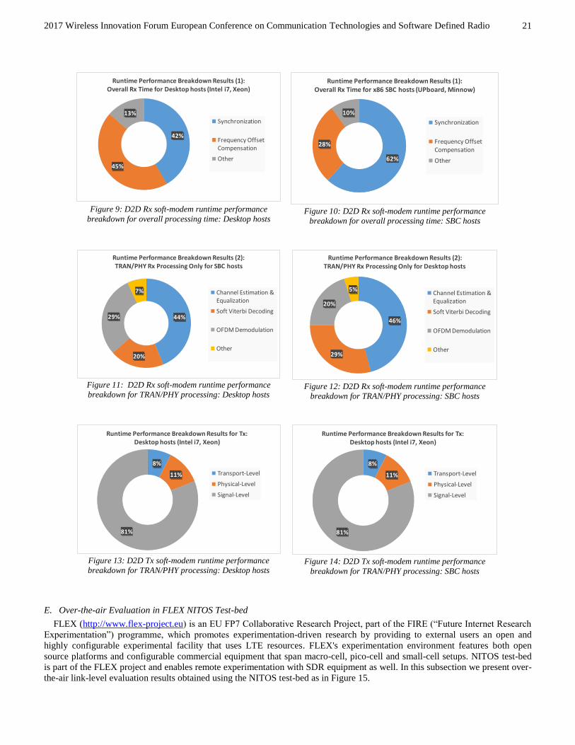
2017 Wireless Innovation Forum European Conference on Communication Technologies and Software Defined Radio
21
Figure 9: D2D Rx soft-modem runtime performance
breakdown for overall processing time: Desktop hosts
Figure 10: D2D Rx soft-modem runtime performance
breakdown for overall processing time: SBC hosts
Figure 11: D2D Rx soft-modem runtime performance
breakdown for TRAN/PHY processing: Desktop hosts
Figure 12: D2D Rx soft-modem runtime performance
breakdown for TRAN/PHY processing: SBC hosts
Figure 13: D2D Tx soft-modem runtime performance
breakdown for TRAN/PHY processing: Desktop hosts
Figure 14: D2D Tx soft-modem runtime performance
breakdown for TRAN/PHY processing: SBC hosts
E. Over-the-air Evaluation in FLEX NITOS Test-bed
FLEX (http://www.flex-project.eu) is an EU FP7 Collaborative Research Project, part of the FIRE (“Future Internet Research
Experimentation”) programme, which promotes experimentation-driven research by providing to external users an open and
highly configurable experimental facility that uses LTE resources. FLEX's experimentation environment features both open
source platforms and configurable commercial equipment that span macro-cell, pico-cell and small-cell setups. NITOS test-bed
is part of the FLEX project and enables remote experimentation with SDR equipment as well. In this subsection we present over-
the-air link-level evaluation results obtained using the NITOS test-bed as in Figure 15.
42%
45%
13%
Runtime Performance Breakdown Results (1): Overall Rx Time for Desktop hosts (Intel i7, Xeon)
Synchronization
Frequency Offset Compensation
Other 62%
28%
10%
Runtime Performance Breakdown Results (1): Overall Rx Time for x86 SBC hosts (UPboard, Minnow)
Synchronization
Frequency Offset Compensation
Other
44%
20%
29%
7%
Runtime Performance Breakdown Results (2): TRAN/PHY Rx Processing Only for SBC hosts
Channel Estimation & Equalization
Soft Viterbi Decoding
OFDM Demodulation
Other
46%
29%
20%
5%
Runtime Performance Breakdown Results (2): TRAN/PHY Rx Processing Only for Desktop hosts
Channel Estimation & Equalization
Soft Viterbi Decoding
OFDM Demodulation
Other
8%
11%
81%
Runtime Performance Breakdown Results for Tx: Desktop hosts (Intel i7, Xeon)
Transport-Level
Physical-Level
Signal-Level
8%
11%
81%
Runtime Performance Breakdown Results for Tx: Desktop hosts (Intel i7, Xeon)
Transport-Level
Physical-Level
Signal-Level

2017 Wireless Innovation Forum European Conference on Communication Technologies and Software Defined Radio
22
Figure 15: D2D Software Modem Experimental Setup in FLEX NITOS Test-Bed
A baseline D2D radio link has been configured and tested in the NITOS platform, using two USRP-equipped nodes.
Currently, the sidelink broadcast channel is fully supported by the real-time software modem implementation, thus we have
performed tests only for the specific mode. The particular experimental evaluation has a significant added value compared to the
simulation-based evaluation performed in Section III.C, as it enables:
The assessment of signal detection and time recovery capabilities of the D2D radio receiver;
The assessment of frequency-offset estimation/compensation mechanisms accuracy, since real hardware modules
induce signal non-idealities in the tested transceiver chain (“hardware-in-the-loop”);
The overall receiver performance evaluation in real –and not model-based– channel conditions, and the comparison
with simulated-based studies.
In particular:
A NITOS node has been used for hosting the transmitting D2D radio and another one for hosting the receiving D2D
radio. Both nodes are equipped with USRP SDR boards, which support the standard LTE/D2D sampling rates.
Tests have been performed for a carrier frequency of 2560 MHz; this is the UL frequency of Band 7 EARFCN 3350
(DL)/21350 (UL) FDD paired carrier.
The receiving USRP gain has been fixed to 40 dB, whereas the transmitting gain (thus the D2D transmission power
level) has been varied from 75 dB down to 39.5 dB, in order to cover a wide dynamic range (~35 dB) of signal
reception levels, and investigate the PHY performance even at very extreme signal conditions.
For each Tx gain configuration we continuously transmit a sidelink broadcast waveform and record at the receiving
node 2,000 I/Q blocks as coming from the USRP board. Then, the soft-modem is applied for recovering the sidelink
broadcast subframes information, i.e. MIB-SL, which carries the bandwidth mode and the sidelink frame/subframe
timing. Based on decoding outcomes the following PHY metrics are extracted as a function of estimated (EVM-based)
SNR:
o PSBCH Bit Error Rate;
o MIB-SL Success Detection Ratio;
The evaluation results are presented in Figure 16 along with results obtained from simulation for the sidelink broadcast channel
in Section III.C. Based on the experimental outcomes the following are concluded:
A wide system operation range has been indeed experimentally evaluated as demonstrated by the depicted estimated
SNR range.
The experimental (over-the-air) performance is slightly worse than that of the simulated performance under noise
channel conditions but better than the simulated performance under time-varying fading channel. The former is
expected since hardware non-idealities induce non-AWGN signal corruption effects, which are not perfectly
compensated during the recovery process (synchronization, frequency offset compensation, and channel
estimation/equalization). The latter is attributed to the stationary channel conditions prevailing in the test-bed.
Experimental Configuration:1. Two NITOS SDR Nodes equipped with a USRP B210 and an i7 Linux Host.2. FLEX-D D2D Software Modem Code loaded in Nodes.3. Tx Node configured with different Tx powers transmits the Sidelink Broadcast Channel.4. Rx Node tries to decodes the Sidelink Broadcast Channel.
FLEX-D D2D Radio Tx Soft-Modem Code
Experimental Output:1. PHY evaluation (BER, MIB-SL Detection Ratio) 2. Comparison with Simulation-based evaluation
Track #2: D2D Experimentation
FLEX-D D2D Radio Rx Soft-Modem Code
D2D Transmitter D2D Receiver
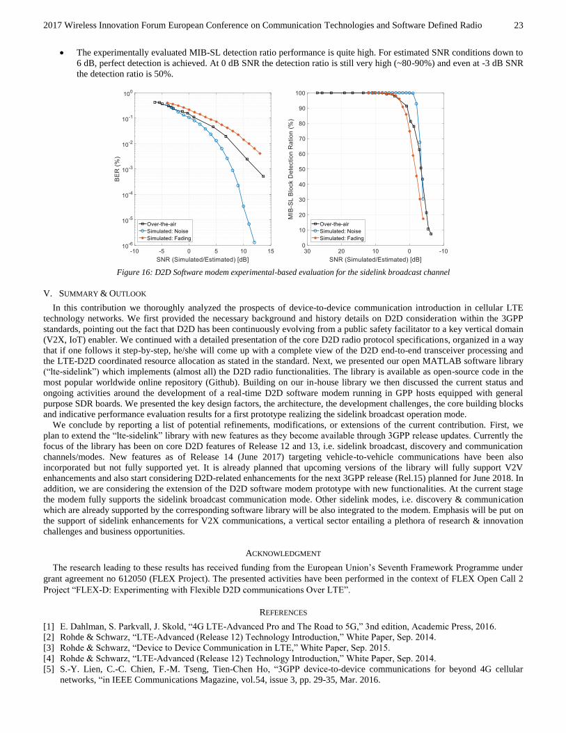
2017 Wireless Innovation Forum European Conference on Communication Technologies and Software Defined Radio
23
The experimentally evaluated MIB-SL detection ratio performance is quite high. For estimated SNR conditions down to
6 dB, perfect detection is achieved. At 0 dB SNR the detection ratio is still very high (~80-90%) and even at -3 dB SNR
the detection ratio is 50%.
Figure 16: D2D Software modem experimental-based evaluation for the sidelink broadcast channel
V. SUMMARY & OUTLOOK
In this contribution we thoroughly analyzed the prospects of device-to-device communication introduction in cellular LTE
technology networks. We first provided the necessary background and history details on D2D consideration within the 3GPP
standards, pointing out the fact that D2D has been continuously evolving from a public safety facilitator to a key vertical domain
(V2X, IoT) enabler. We continued with a detailed presentation of the core D2D radio protocol specifications, organized in a way
that if one follows it step-by-step, he/she will come up with a complete view of the D2D end-to-end transceiver processing and
the LTE-D2D coordinated resource allocation as stated in the standard. Next, we presented our open MATLAB software library
(“lte-sidelink”) which implements (almost all) the D2D radio functionalities. The library is available as open-source code in the
most popular worldwide online repository (Github). Building on our in-house library we then discussed the current status and
ongoing activities around the development of a real-time D2D software modem running in GPP hosts equipped with general
purpose SDR boards. We presented the key design factors, the architecture, the development challenges, the core building blocks
and indicative performance evaluation results for a first prototype realizing the sidelink broadcast operation mode.
We conclude by reporting a list of potential refinements, modifications, or extensions of the current contribution. First, we
plan to extend the “lte-sidelink” library with new features as they become available through 3GPP release updates. Currently the
focus of the library has been on core D2D features of Release 12 and 13, i.e. sidelink broadcast, discovery and communication
channels/modes. New features as of Release 14 (June 2017) targeting vehicle-to-vehicle communications have been also
incorporated but not fully supported yet. It is already planned that upcoming versions of the library will fully support V2V
enhancements and also start considering D2D-related enhancements for the next 3GPP release (Rel.15) planned for June 2018. In
addition, we are considering the extension of the D2D software modem prototype with new functionalities. At the current stage
the modem fully supports the sidelink broadcast communication mode. Other sidelink modes, i.e. discovery & communication
which are already supported by the corresponding software library will be also integrated to the modem. Emphasis will be put on
the support of sidelink enhancements for V2X communications, a vertical sector entailing a plethora of research & innovation
challenges and business opportunities.
ACKNOWLEDGMENT
The research leading to these results has received funding from the European Union’s Seventh Framework Programme under
grant agreement no 612050 (FLEX Project). The presented activities have been performed in the context of FLEX Open Call 2
Project “FLEX-D: Experimenting with Flexible D2D communications Over LTE”.
REFERENCES
[1] E. Dahlman, S. Parkvall, J. Skold, “4G LTE-Advanced Pro and The Road to 5G,” 3nd edition, Academic Press, 2016.
[2] Rohde & Schwarz, “LTE-Advanced (Release 12) Technology Introduction,” White Paper, Sep. 2014.
[3] Rohde & Schwarz, “Device to Device Communication in LTE,” White Paper, Sep. 2015.
[4] Rohde & Schwarz, “LTE-Advanced (Release 12) Technology Introduction,” White Paper, Sep. 2014.
[5] S.-Y. Lien, C.-C. Chien, F.-M. Tseng, Tien-Chen Ho, “3GPP device-to-device communications for beyond 4G cellular
networks, “in IEEE Communications Magazine, vol.54, issue 3, pp. 29-35, Mar. 2016.

2017 Wireless Innovation Forum European Conference on Communication Technologies and Software Defined Radio
24
[6] 3GPP TR 22.803, “Feasibility study for Proximity Services (ProSe) (Release 12),” TR v.12.2.0, Jun. 2013.
[7] 3GPP TR 36.843, “Study on LTE Device to Device Proximity Services; Radio Aspects (Release 12)” TR v12.0.1, Mar.,
2014
[8] 3GPP TR 36.877, “Study on LTE Device to Device Proximity Services; User Equipment (UE) radio transmission and
reception (Release 12)” TR v12.0.0, Mar., 2014
[9] 3GPP RP-161839, “Further Enhancements to LTE Device to Device, UE to Network Relays for IoT and Wearables
(FS_feD2D_IoT_relay_wearable), “3GPP TSG RAN Meeting #73, New Orleans, September 19 - 22, 2016
[10] 3GPP TS 36.211, “Evolved Universal Terrestrial Radio Access (E-UTRA); Physical channels and modulation (Release 14)”
TS v14.0.0, Sep., 2016
[11] 3GPP TS 24.334, “Proximity-services (ProSe) User Equipment (UE) to ProSe function protocol aspects; Stage 3 (Release
13),” TS v.13.3.0, Mar. 2016
[12] 3GPP TS 23.003, “Numbering, addressing and identification (Release 13),” TS v.13.6.0, Jun. 2016
[13] 3GPP TS 36.212, “Evolved Universal Terrestrial Radio Access (E-UTRA); Multiplexing and channel coding (Release 14)”
TS v14.0.0, Sep., 2016
[14] 3GPP TS 36.213, “Evolved Universal Terrestrial Radio Access (E-UTRA); Physical layer procedures (Release 14)” TS
v14.0.0, Sep., 2016
[15] 3GPP TS 36.321, “Evolved Universal Terrestrial Radio Access (E-UTRA); Medium Access Control (MAC) protocol
specification (Release 14)” TS v13.0.0, Sep., 2016
[16] 3GPP TS 23.303, “Proximity-based Services (ProSe); Stage 2 (Release 14),” TS v.14.1.0, Dec. 2016
[17] "CISQ Specifications for Automated Quality Characteristic Measures", OMG 2012
[18] "The GNU C Programming Tutorial", Edition 4.1
[19] Sandra Loosemore with Richard M. Stallman, Roland McGrath, Andrew Oram, and Ulrich Drepper, "The GNU C Library
Reference Manual", version 2.24
[20] Alan Thomas, CCNA, CCSI, Global Knowledge Instructor, "The Packet Delivery Process: Remotely Connected Hosts",
2014
[21] Jin-Soo Kim, Kangho Kim, Sung-In Jung (2001), "Building a high-performance communication layer over virtual interface
architecture on Linux clusters", Proceedings of the 15th international conference on Supercomputing, ACM: 335–347, 2009-
02-09
[22] Robert Love, "Kernel Korner CPU Affinity", Linux Journal #111, July 2003
[23] R. A. Shafik, M. S. Rahman and A. R. Islam, "On the Extended Relationships Among EVM, BER and SNR as Performance
Metrics," 2006 International Conference on Electrical and Computer Engineering, Dhaka, 2006, pp. 408-411.


![Energy-Efficient Matching for Resource Allocation in D2D ...source allocation problems for D2D communications are sum-marized and compared as follows. In [40], matching theory was](https://img.dokumen.tips/doc/110x75/60028dfc13eaa868cb151da6/energy-efficient-matching-for-resource-allocation-in-d2d-source-allocation-problems.jpg)