Embed Size (px)
Citation preview

International Journal of Smart Grid and Clean Energy
Experimental study on aerodynamic characteristics of
vertical-axis wind turbine
Yihuai Hua*
, Taiyou Wanga, Hao Jin
a, Xianfeng Cao
b, Chen Zhang
b
a Shanghai Maritime University, No. 1550 Pudong Avenue, Shanghai China and 201306, China b AVIC Dingheng Shipbuilding Company Jiangdu Economic & Development Zone, Jiangsu and 225200, China
Abstract
This paper firstly introduces some parameters for the design of vertical-axis wind turbine including sweeping area,
blade aspect ratio, number of blades, airfoil type, turbine solidity, blade shape and height/diameter ratio. Models of
Cup-Rotor, Φ-Rotor and H-Rotor vertical-axis wind turbine were made and aerodynamic experiments were carried
out in a wind tunnel laboratory on these typical vertical-axis wind turbines. Experimental results are analyzed, which
reveal the influence of the structural parameters on the aerodynamic performance of these wind turbines. When a
baffle plate is put in front of the Cup-Rotor wind turbine, its rotational velocity and tip-speed ratio will be higher, and
the tip-speed ratio will be over 1.0. Airfoil type has little influence on the minimum steady running speed of Φ-Rotor
wind turbine and some influence on the turning point speed. Initial triggering could greatly enlarge the rotational
velocity and the tip-speed ratio of the Φ-Rotor vertical-axis wind turbines and improve its working efficiency. The H-
Rotor wind turbine has higher minimum steady running speed and lower tip-speed ratio, which needs more attention
and carful optimization.
Keywords: Aerodynamic analysis; renewable energy application; vertical-axis wind turbine; wind tunnel test
1. Introduction
Due to its simple structure, low working noise, high working stability, simple maintenance and fine
appearance, vertical-axis wind turbine has been more and more widely used in wind energy
application [1]-[6]
difficult [7], which somehow limits its application to some extent.
There are two types of vertical-axis wind turbines including drag type and lift type wind turbines
according to their working principle of wind turbine blades. Drag type wind turbine mainly uses air
resistance force to rotate its blades while air flowing through them. These asymmetrical blades produces
different aerodynamic resistance forces in the upwind direction, which results in a moment round a
central axis driving the wind turbine such as cup-Rotor wind turbine. Lift type wind turbine uses lift force
generated by the air blowing through the blades. There are two kinds of lift type vertical-axis wind
turbine as Φ-Rotor vertical-axis wind turbine and H-Rotor vertical-axis wind turbine. They have
relatively simpler structures, lower cost, higher rotational velocity, bigger rotational inertia and are
suitable for large-scaled wind turbine. Because of its small windward area, Φ-Rotor vertical-axis wind
turbine has poor starting-up performance and should be equipped with a starting mechanism and a clutch,
which increases the complexity of structure and investment.
Aerodynamic experiments were carried out in a wind tunnel laboratory on three typical vertical-axis
wind turbines. The experiment results reveal the influence of structural parameters on the aerodynamic
performance of these wind turbines and lay foundation of practical application of these vertical-axis wind
turbines.
*Manuscript received November 20, 2016; revised January 20, 2017.
Corresponding author. Tel.: +86-21-38282929; E-mail address: [email protected].
doi: 10.12720/sgce.6.2.104-113
. But its aerodynamic performance is quite puzzling and its structural design is more
2. Structural Design of Vertical-Axis Wind Turbine
Some important structural parameters could influence the performance of vertical-axis wind turbine
including sweeping area, blade aspect ratio, number of blades, airfoil, solidity, blade shape and height
/diameter ratio.
2.1. Sweeping area
The sweeping area of wind turbine is the swept area by blades within one revolution perpendicular to
wind direction, which directly determines the total amount of captured wind energy. The sweeping area is
determined by the radius and height of wind turbine. This sweeping area could be estimated from rated
power, rated speed and wind energy utilization coefficient of wind turbine. This parameter is then used to
determine the overall size of wind turbine and to design its components.
2.2. Blade aspect ratio
The blade aspect ratio is the ratio of blade height to its chord. When the wind turbine runs at a certain
velocity, the air pressure on pressure side is higher than that on suction side, resulting in upward lift force
from its pressure difference. Due to this pressure difference on blade surface, the air on pressure side will
orbit up from both ends of blade, which generates wing tip vortex. The normal flow on both ends will be
disturbed by this vortex and lift force will be reduced. The larger the lift coefficient is, the larger the wing
tip vortex will be, and a series of vortex will be formed near the wing tip behind the blade end and
increase the blade resistance. If the aspect ratio is large enough, the lift loss and increased resistance
caused by the wing tip vortex could be ignored; if the aspect ratio is relatively small, this influence will be
obvious. Due to the limited blade length, the larger the aspect ratio is, the narrower the blade will be,
resulting in smaller blade area and total lift force. In addition, narrower chord will result in smaller
Reynolds number, smaller stall attack angle of the blade, smaller lift coefficient and larger drag
coefficient. Sometime a end plate is installed on the blade tip to reduce the influence of circling flow.
2.3. Number of blades
The number of blades directly determines the total cost, aerodynamic performance and load
distribution of wind turbine. At present, Darrieus type wind turbine mostly has two or three blades. Three-
blade wind turbine is the most widely used, which has small torque disturbance, good aerodynamic
performance. Two-blade wind turbine is also used with less material and investment. The comparisons
between these two kinds of wind turbine are shown in Table 1.
Table 1. Comparison between two-blade and three-blade wind turbines
Performance index Two-blade wind turbine Three-blade wind turbine
Manufacture technology Poor Good
Material cost Low High
Installation cost Low High
Torque disturbance Poor Good
Mechanical properties Poor Good
Strength/mass ratio Good Poor
2.4. Airfoil type
Airfoil type could directly determine energy transformation coefficient, blade cost, load distribution of
wind turbine. Lift/drag ratio is an important index to indicate the performance of airfoil. NACA00XX
type airfoil is usually adopted by Darrieus wind turbines with high lift, low drag and good stall
characteristics [8]. The NACA0015 type airfoil drawn by ProfiliV2 is shown in Fig. 1.
Yihuai Hu et al: Experimental study on aerodynamic characteristics of vertical-axis wind turbine 105

Fig. 1. Section view of NACA0015 airfoil.
2.5. Turbine solidity
Turbine solidity is an important parameter of vertical-axis wind turbine, which is the spreading surface
of blades divided by the sweeping area as indicated in formula (1) as.
σ =Bcl
S (1)
where
σ——turbine solidity
B—— number of blades
c——blade chord (m)
l——blade length (m)
S——sweeping area (m2)
For simplicity, it could be also calculated as:
σ =Bc
R (2)
where
R——rotor radius (m)
The energy transformation coefficient of vertical-axis wind turbine could be reduced when the turbine
solidity is too large or too small. Larger turbine solidity could increase larger drag force and decrease
wind velocity onto the blades, resulting in the moving of high rotating torque attack angle on blades to
low tip-speed ratio area. So the vertical-axis wind turbine with small solidity could have higher tip-speed
ratio than that with large solidity [9]. But the vertical-axis wind turbine with larger solidity has better
starting-up feature than that with smaller solidity. Some other parameters should be taken into account
such as number of blades, blade chord and tip-speed ratio in the design of vertical-axis wind turbine. To
reduce the cost of wind turbine, small turbine solidity is a better choice.
2.6. Blade shape
Different wind turbine has different blade shape. Drag type cup-Rotor wind turbine is made from bent
semi-circled iron plate, which is enforced by ribs and brackets. After years’ research and practice, blade
shape of Φ-Rotor wind turbine has been gradually developed into several curves including troposkien,
sandia, catenaries and parabola type. The troposkien type blade is flexible and fixed at tow ends, which
rotates around a fixed axis and is naturally bent into curve by its centrifugal force. The sandia type blade
is simplified from troposkien blade with arc segment in the middle and straight parts at two ends
symmetrically distributed by equatorial plane. The catenaries curve is a line with uniform material and
constant cross-section hung at its two ends on the horizon with gravity. The parabola type is a kind of
catenaries. Parabolic type Φ-Rotor wind turbine and H-Rotor wind turbine with vertically straight blades
of NACA00XX airfoil were made models for the experiments.
2.7. Height /diameter ratio
Height/diameter ratio of the wind turbine is the height to its diameter. Under the same sweeping area
the wind turbine is usually designed with small height /diameter ratio in order to minimize the length of
blade and the height of central pole. But it has large rotating torque under low speed, higher stress on
International Journal of Smart Grid and Clean Energy, vol. 6, no. 2, April 2017106

blade from gravity, higher cost for driving mechanism. Modern design of vertical-axis wind turbine tends
to be larger height/diameter ratio, which could capture more amount of and more stable wind energy. But
it needs carefully material and strength design and supporting structure. Generally speaking, the
height/diameter ratio of the vertical-axis wind turbine is better between 0.5 and 3.0 [9].
Models of Cup-Rotor, Φ-Rotor and H-Rotor vertical-axis wind turbine were made as shown in Fig. 2
(a), (b), (c). Cup-Rotor wind turbine has semicircle blade and Φ-Rotor, H-Rotor wind turbines use
NACA0012, NACA0015, NACA0018, NACA0021 and NACA0024 type airfoils.
(a) (b) (c)
Fig. 2. Three types of vertical-axis wind turbine models: (a)semicircle Cup-Rotor, (b)Φ-Rotor, (c)H-Rotor.
3. Wind Tunnel Test
The experiments were carried out respectively on those three kinds of vertical-axis wind turbine
models in a wind tunnel laboratory of Shanghai Maritime University with a velocity measuring device in
a tunnel tank.
The wind tunnel is a low-speed, recycling wind system. The flow field parameters are shown below:
Wind speed range: 1~40 m/s;
Airflow stability: <±0.4%;
Airflow deflection: < ±0.5°;
Airflow turbulence intensity: <0.5%;
Airflow unevenness: < ±0.4%;
3.1. Velocity measuring device
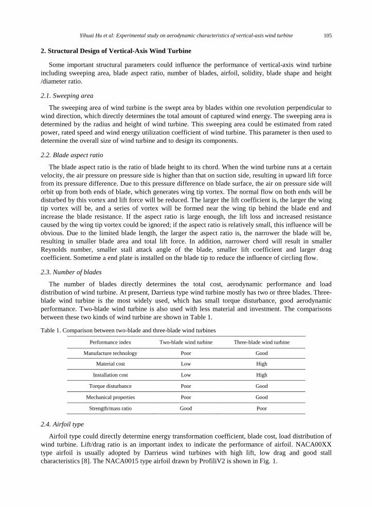
A velocity measuring device is designed according to the wind tunnel size, tunnel tank and vertical-
axis wind turbine model structure as shown in Fig. 3 (a), (b). The device is composed of common bearing,
thrust bearing, sleeve, bracket, base and support frame.
According to the size of the wind tunnel, inner tank and the structure of vertical-axis wind turbine, a
velocity measuring device of the wind turbine is designed; its structure size and physical map are shown
in Fig. 3 (a), (b). The device is composed of common bearing, thrust bearing, sleeve, bracket, base and
support frame. The shaft of vertical-axis wind turbine model is inserted into the sleeve and its rotational
velocity will be measured by photoelectric sensor as shown in Fig. 4.
The photoelectric velocity measuring device is mainly composed of rotating member, reflecting sticker
and reflecting photoelectric sensor with measuring range of 1~60000 r/min and operating temperature
Yihuai Hu et al: Experimental study on aerodynamic characteristics of vertical-axis wind turbine 107
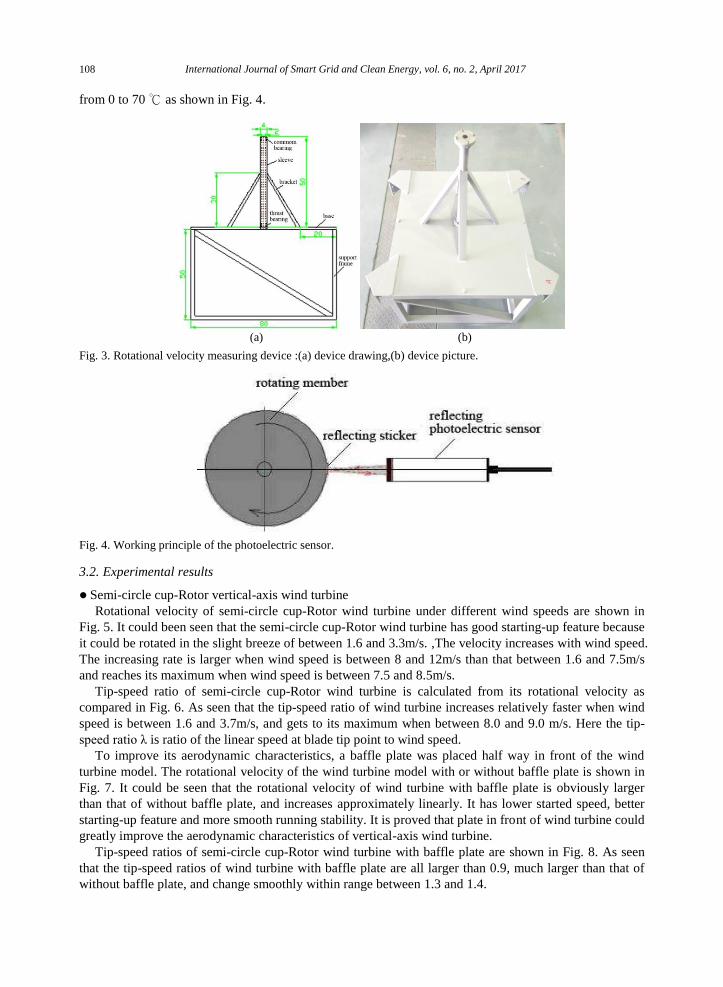
from 0 to 70 ℃ as shown in Fig. 4.
(a) (b)
Fig. 3. Rotational velocity measuring device :(a) device drawing,(b) device picture.
Fig. 4. Working principle of the photoelectric sensor.
3.2. Experimental results
Semi-circle cup-Rotor vertical-axis wind turbine
Rotational velocity of semi-circle cup-Rotor wind turbine under different wind speeds are shown in
Fig. 5. It could been seen that the semi-circle cup-Rotor wind turbine has good starting-up feature because
it could be rotated in the slight breeze of between 1.6 and 3.3m/s. ,The velocity increases with wind speed.
The increasing rate is larger when wind speed is between 8 and 12m/s than that between 1.6 and 7.5m/s
and reaches its maximum when wind speed is between 7.5 and 8.5m/s.
Tip-speed ratio of semi-circle cup-Rotor wind turbine is calculated from its rotational velocity as
compared in Fig. 6. As seen that the tip-speed ratio of wind turbine increases relatively faster when wind
speed is between 1.6 and 3.7m/s, and gets to its maximum when between 8.0 and 9.0 m/s. Here the tip-
speed ratio λ is ratio of the linear speed at blade tip point to wind speed.
To improve its aerodynamic characteristics, a baffle plate was placed half way in front of the wind
turbine model. The rotational velocity of the wind turbine model with or without baffle plate is shown in
Fig. 7. It could be seen that the rotational velocity of wind turbine with baffle plate is obviously larger
than that of without baffle plate, and increases approximately linearly. It has lower started speed, better
starting-up feature and more smooth running stability. It is proved that plate in front of wind turbine could
greatly improve the aerodynamic characteristics of vertical-axis wind turbine.
Tip-speed ratios of semi-circle cup-Rotor wind turbine with baffle plate are shown in Fig. 8. As seen
that the tip-speed ratios of wind turbine with baffle plate are all larger than 0.9, much larger than that of
without baffle plate, and change smoothly within range between 1.3 and 1.4.
International Journal of Smart Grid and Clean Energy, vol. 6, no. 2, April 2017108

Fig. 5. Rotational velocity of semi-circle cup-Rotor wind turbine under different wind speeds.
Fig. 6. Tip-speed ratio of semi-circle cup-Rotor wind turbine under different wind speeds.
Fig. 7. Rotational velocity of semi-circle cup-Rotor wind turbine with or without baffle plate.
Fig. 8. Tip-speed ratio of semi-circle cup-Rotor wind turbine with or without baffle plate.
Yihuai Hu et al: Experimental study on aerodynamic characteristics of vertical-axis wind turbine 109

Φ-Rotor vertical-axis wind turbine
The rotational velocities of Φ-Rotor vertical-axis wind turbine models with the same height and
diameter and different airfoil type as NACA0012, NACA0015, NACA0018, NACA0021, NACA0024
are shown in Fig. 9.
The rotational velocity was measured when the Φ-Rotor wind turbine run steadily under some a wind
speed. As seen from the Fig. 9 that without initial Triggering, rotational velocities of these five types of
wind turbines increase linearly with wind speed under lower wind speed range, but then increase
dramatically at a certain speed, indicating a turning point where low speed turns to high speed. The steady
running speeds of five airfoil wind turbines are quite different, where NACA0024 airfoil has the lowest
minimum steady wind speed around 7.4 m/s and NACA0012 airfoil gas the highest minimum steady
wind speed around 8.6 m/s. The steady running speed and turning point of the five airfoils are listed in
Table 2.
Table 2. The steady running speed and turning point of the five airfoils
Among these five different airfoils without initial trigging, the thicker the blade is, the lower the
turning point speed will be and the corresponding rotational velocities all below 250 r/min. When all the
wind turbines were trigged to an initial rotational velocity 250 r/min, the experimental results are shown
in Fig. 10. As seen that the velocities of these five different airfoils increase with wind speed linearly,
where NACA0015 airfoil has the lowest steady wind speed and NACA0012 airfoil has the highest steady
wind speed. The minimum steady wind speed of all the five airfoils are between 3.0 and 4.0 m/s as listed
in Table 3. It could be seen from the comparison between Fig. 9 and Fig. 10 that when Φ-Rotor wind
turbine is trigged at an initial velocity 250 r/min, its velocity is higher than that of without initial velocity.
So the initial Triggering of Φ-Rotor wind turbine is necessary for its higher working efficiency.
Table 3. The minimum steady wind speed and rotational velocity under the 10m/s wind speed
Fig. 9. Rotational velocity of Φ-Rotor wind turbine without initial trigging.
The calculated tip-speed ratios under different wind speed are shown in Fig. 11 and Fig. 12
respectively. As seen from Fig. 11 that when the airfoils are not initially trigged at 250 r/min the tip-speed
ratio increases with wind speed before the turning point. As seen from Fig. 12 that with or without initial
triggering the tip-speed ratio increase with wind speed and NACA0015 has the largest stability. But all
Airfoil type NACA0012 NACA0015 NACA0018 NACA0021 NACA0024
Minimum steady running
speed(m/s) 8.6 7.4 8.3 7.8 7.4
Turning point speed,m/s 14.9 12.3 13.5 9.5 9.0
Airfoil type NACA0012 NACA0015 NACA0018 NACA0021 NACA0024
Minimum steady running speed, m/s 3.9 3.3 3.4 3.5 3.8
Rotational velocity under 10m/s wind
speed, r/min 1091.4 1088.0 1040.2 987.8 1004.8
International Journal of Smart Grid and Clean Energy, vol. 6, no. 2, April 2017110

the tip-speed ratios present a fluctuation from 4.5 to 5.5 m/s wind speed, especially the NACA0012 has
two big fluctuations.
Fig. 10. Rotational velocity of Φ-Rotor wind turbine with 250r/m initial trigging.
Fig. 11. Tip-speed ratio of Φ-Rotor wind turbine without initial trigging.
Fig. 12. Tip-speed ratio of Φ-Rotor wind turbine with 250r/min initial Triggering.
Fig. 13. Relationship between Tip-speed ratio λ and power co efficiency Cp of Φ-Rotor wind turbine.
Yihuai Hu et al: Experimental study on aerodynamic characteristics of vertical-axis wind turbine 111

Fig. 13 indicates the relationship between power coefficient Cp and tip-speed ratioλ. Here the power
coefficient is the ratio of the wind turbine power to its encountered wind power. From Fig. 11 and Fig. 13
it could be seen that power coefficients are almost zero before turning point without initial trigging. From
Fig. 12 and Fig. 13 it could be seen that the power coefficients are all above 0.3 when power coefficient is
between 2.7 and 5.2 while wind turbine was initially trigged at 250 r/min velocity and all these wind
turbines reach their highest power coefficient. So the Φ-Rotor wind turbine could have higher working
efficiency and higher wind power coefficient at the low wind speed if initially trigged at 250 r/min
velocity.
H-Rotor vertical-axis wind turbine
In the case of same structure parameters such as height and diameter of wind turbine, rotational
velocities of five H-Rotor vertical-axis wind turbines with different airfoils of NACA0012, NACA0015,
NACA0018, NACA0021 and NACA0024 were measured as shown in Fig. 14.
The rotational velocity of the H-Rotor wind turbine was measured, respectively when five different
wind turbine models run steadily. As seen from Fig. 14 that all the H-Rotor wind turbines run steadily
under high wind speed above 15.0 m/s, except that with NACA0024 airfoil type which could run above
9.5 m/s. Their rotational velocity all increase with wind speed nearly linearly.
The tip-speed ratio of H-Rotor wind turbine is calculated as shown in Fig. 15. All the tip-speed ratios
of H-Rotor wind turbines increase with wind speed gradually, most of which are below 0.20 even under
strong wind.
Fig. 14. Rotational velocity of five different H-Rotor airfoils wind turbine.
Fig. 15. Tip-speed ratio of five different H-Rotor airfoils wind turbine.
4. Conclusion
Through theoretical analysis and experimental study, some conclusions are drawn out as below:
The starting-up wind speed of semi-circle Cup-Rotor vertical-axis wind turbine is about 1.6 m/s, the
rotational velocity and the tip-speed ratio increases with wind speed from 1.6 m/s to 12m/s. When a
baffle plate is put in front of windward convex part of the Cup-rotor wind turbine, its rotational
International Journal of Smart Grid and Clean Energy, vol. 6, no. 2, April 2017112

velocity and tip-speed ratio will be higher, and the tip-speed ratio will be over 1.0.
The rotational velocities of the five Φ-Rotor vertical-axis wind turbines gradually increase
approximately linearly with wind speed within a certain range of wind speed, and then increase rapidly
after a certain turning point when they were initially trigged. Airfoil type has little influence on the
minimum steady running speed of Φ-rotor wind turbine and some influence on the turning point speed.
When the Φ-Rotor vertical-axis wind turbine is initially trigged at 250 r/min the rotational velocity and
tip-speed ratio will be much larger and increase with wind speed approximately linearly, which
indicates that initial triggering could greatly enlarge the rotational velocity and the tip-speed ratio of
the Φ-Rotor vertical-axis wind turbines and finally improve its working efficiency. At this time, airfoil
type has little influence on their minimum steady running speed and performance.
Compared with the semi-circle Cup-Rotor and Φ-Rotor vertical-axis wind turbine, the H-Rotor wind
turbine has higher minimum steady running speed and lower tip-speed ratio, which indicates that the
aerodynamic design and structure manufacture of H-Rotor wind turbine needs more attention and
carful optimization.
References
[1] Islam M.R, Mekhilef S, Saidur R. Progress and recent trends of wind energy technology. Renewable and Sustainable Energy
Reviews, 2013; 21:456-468.
[2] Andrea A, Antonio E, Antonio M, et al. 3D CFD analysis of a vertical-axis wind turbine. Energies, 2015; 8(4):3013-3033.
[3] Elkhoury M, Kiwata T, Aoun E. Experimental and numerical investigation of a three-dimensional vertical-axis wind turbine
with variable-pitch. Journal of Wind Engineering and Industrial Aerodynamics, 2015; 139:111-123.
[4] Nasir H, Ahmed UF. Vertical-axis wind turbine—A review of various configurations and design techniques. Renewable and
Sustainable Energy Reviews, 2012; 16:1926-1939.
[5] Yang Y, Pan W, Zhu H. An overview and recent research progress of vertical-axis wind turbine. China Mechanical
Engineering.2013; 24(5):703-709.
[6] Xin J, Gaoyuan Z, Kejun G, et al. Darrieus vertical-axis wind turbine: Basic research methods. Renewable and Sustainable
Energy Reviews, 2015; 42:212-225.
[7] DING G, Li Y, Wang S, et al. Wind tunnel test on effects of solidity of performance of vertical-axis wind turbine. Renewable
Energy Resource, 2013; 31(9):58-62.
[8] Cai X, Gao Q, Pan P, et al. Vertical-axis Wind Turbine. 1st ed. Beijing: China Water & Power Press; 2016.
[9] Li Y. Technical lecture about vertical-axis wind turbine-design and experiment about vertical-axis wind turbine. Renewable
Energy Resource, 2009; 27(5):120-122.
Yihuai Hu et al: Experimental study on aerodynamic characteristics of vertical-axis wind turbine 113


![Aerodynamic Features of French Fricatives...fricatives. 2. Methodology 2.1. Experimental setup The experimental procedure follows the same conditions as presented in [9: 79-80], in](https://img.dokumen.tips/doc/110x75/5f9aa3787ce6a237e646c824/aerodynamic-features-of-french-fricatives-fricatives-2-methodology-21-experimental.jpg)