Embed Size (px)
DESCRIPTION
Wood Construction
Citation preview
DOI 10.1007/s00107-009-0313-5
O R I G I N A L S · O R I G I N A L A R B E I T E N
Eur. J. Wood Prod. (2009) 67: 211–218
Experimental study of cross-laminated timber wall panels
Johan Vessby · Bertil Enquist · Hans Petersson · Tomas Alsmarker
Received: 4 July 2008 / Published online: 19 February 2009© Springer-Verlag 2009
Abstract The use of cross-laminated structural timber elem-ents is becoming increasingly popular. The number of layersvaries normally from three upwards. The structural perform-ance of five-layer cross-laminated timber elements was in-vestigated. The five layers consisted of 19 mm thick boards,laid successively at right angles to each other and gluedtogether with PU-adhesive, layers 1, 3 and 5 lying in onedirection and layers 2 and 4 in the other. The stiffness andstrength of four cross-laminated timber elements (4955 mmlong, 1250 mm wide and 96 mm thick) were studied duringin-plane bending. Two of the elements were first partitionedinto two parts that were reconnected in two different waysprior to testing. The influence of the way in which the cross-laminated timber elements were reconnected was studied,the behaviour observed being compared with the test resultsfor the unpartitioned specimens with respect to both strengthand stiffness. The experimental tests performed showed thecross-laminated timber elements to possess a high degree ofstiffness and strength. There was also found to be a markeddifference in behaviour between the two different ways inwhich the elements were connected to each other. One of thetwo connecting methods studied, being of less good designbut earlier frequently used in Sweden, showed as expectedpoor structural performance, whereas the other one appliedas a safer alternative performed well.
J. Vessby (�) · B. Enquist · H. PeterssonDepartment of Design and Technology, Vaxjo University,Luckligs plats 1,351 95 Vaxjo, Swedene-mail: [email protected]
T. AlsmarkerTyrens AB,Peter Myndes Backe 16,118 86 Stockholm, Sweden
Experimentelle Untersuchung von Wandelementenaus Brettsperrholz
Zusammenfassung Die Verwendung von Brettsperrholz-bauteilen aus drei oder mehr Lagen gewinnt zunehmendan Beliebtheit. Das Trag- und Verformungsverhalten vonfunflagigen Brettsperrholzelementen wurde untersucht. Diefunf Lagen bestanden aus 19 mm dicken, kreuzweise mitPU-Klebstoff verklebten Platten, wobei Lagen 1, 3 und 5 ineine Richtung und Lagen 2 und 4 in die andere Richtungorientiert waren. Die Biegesteifigkeit und -festigkeit in Plat-tenebene von vier Brettsperrholzelementen (4955 mm lang,1250 mm breit und 96 mm dick) wurden untersucht. Zweider Elemente wurden in Langsrichtung mittig aufgetrenntund dann vor der Prufung auf zwei verschiedene Artenwieder miteinander verbunden. Untersucht wurde der Ein-fluss der Art der Verbindung der Brettsperrholzelemente aufdie Festigkeit und Steifigkeit der Elemente durch Vergleichmit den Versuchsergebnissen der nicht geteilten Prufkorper.Die Versuche ergaben, dass die Brettsperrholzelemente einehohe Steifigkeit und Festigkeit aufwiesen. Es zeigte sichein deutlicher Unterschied im Verhalten der zwei Arten derWiederverbindung der beiden Elemente. Erwartungsgemaßergab die weniger gute aber fruher in Schweden oft verwen-dete Verbindungsart schlechte Ergebnisse, wohingegen dieandere Verbindung, eine sicherere Alternative, gute Ergeb-nisse lieferte.
1 Introduction
Multi-storey timber-based structures have long been builtin many different countries. Various challenges are con-nected with constructions of this type. One such challenge
1 3

212 Eur. J. Wood Prod. (2009) 67: 211–218
is that of stabilising the structure against horizontal windloads. The most common stabilising system involves theuse of a sheathing material such as OSB, plywood or gyp-sum, connected to the timber frame by nails or screws.Shear forces are thus transmitted by the connectors fromthe timber frame to the sheathing. The wall elements be-tween separate stories are often connected by means ofspecial brackets or some other form of hold-down devices.The design principles involved and the calculation methodsemployed have been dealt with extensively in the litera-ture Kallsner and Lam (1995), Kasal et al. (2004) and Ellisand Bougard (2001). In many cases, a stiffer wind brac-ing system of greater strength may be of interest, partic-ularly in the case of narrow houses that are tall but havea relatively small foundation area. For houses in which thewalls are perforated by door and window openings spe-cial structural design measures are often needed. In suchbuildings, the use of cross-laminated timber elements, ei-ther as parts of the walls or in the walls as a whole, can beof strong interest, a matter which has been studied for ex-ample by Dujic et al. (2004), Blass and Fellmoser (2004)and Moosbrugger et al. (2006). In heavily loaded partsof the walls, the connections between the cross-laminatedwall panels are highly important for structural perform-ance. The aim of the present study was to gain greaterinsight into the behaviour of structures of this type by in-vestigating cross-laminated timber elements experimentally.Both the stiffness and strength of the elements and theways of connecting the wall elements with each other werestudied.
Fig. 1 The five-layercross-laminated timber-wallelements testedAbb. 1 UntersuchteWandelemente aus funflagigemBrettsperrholz
2 Tested specimens
Four wall elements of cross-laminated timber 4955 mm inlength, 1250 mm in width and 96 mm thick were tested.The elements consisted of five layers of sawn boards, thesuccessive layers being glued crosswise to each other. Thefibres of the two outermost layers, 1 and 5, and of themiddle layer, 3, extended in the direction of the length ofthe element, whereas layers 2 and 4 extended in the di-rection perpendicular to this, see Fig. 1. The 19 mm thicksawn boards of which these timber elements were com-posed were made of Norway spruce and were on the averageabout 120 mm in width. In the long direction, the boardswere placed butt to butt with a random location of thebutt joints, there being no finger joints connecting them.The boards were not strength graded but expected to beof class C24 or higher grade. The equilibrium moisturecontent of these elements was found to be about 13% atthe time of testing. The highest and the lowest moisture-content values in a given board differed by about 2%. It isassumed that in the elements tested the variations in the ma-terial properties due to differences in moisture content werenegligible.
3 Testing of joints
After stiffness testing of the elements 1 and 2 at a low loadlevel, these two cross-laminated timber elements were sawninto two parts. These parts were then reconnected by use
1 3

Eur. J. Wood Prod. (2009) 67: 211–218 213
of two different jointing methods. The new wall elementshaving longitudinal joints were renamed as element 5 (madefrom element 1) and element 6 (made from element 2).
For element 5, a purely mechanical joint was employed.After this element had been partitioned, a 60 mm deep and25 mm wide slot was cut into each of the two halves. A sawnboard 120 mm wide, 25 mm thick and graded as C24 was fit-ted into the slot. Hexagonal-head wood screws, 96 mm longand 8 mm in diameter, were screwed both from the left andthe right into the two sides of the element. This poor design,with the solid board and the hexagonal-head screws, of thejoint was used in the experiment since similar joints haveearlier been much used in practical design, although theircapacity has never been verified experimentally. The screwswere mounted in a row both from the first and the secondside in predrilled holes as shown in Fig. 2a. By placing themin a single row like this the worst case was obtained froma shear force perspective.
For element 6 both gluing and screwing were used forthe joint. A sheet of fibreboard of quality C40 (wet pro-cess fibreboard, HB.HLA2, Masonite AB) 300 mm wideand 8 mm thick was applied to both sides of the par-titioned specimen, see Fig. 2b. The adhesive used was
Fig. 2 Joints of the longitudinal wall-elements: (a) element 5 with a sawn board screwed to the parts of the element and (b) element 6 withfiberboard sheets glued and screwed to the parts of the elementAbb. 2 Langsverbindung der Wandelemente (a) Element 5, bei dem die Teile mit einem Brett verschraubt wurden und (b) Element 6, bei demFaserplatten beidseitig mittels Schraubpressklebung aufgeklebt wurden
a single-component polyurethane with a curing time ofapproximately 12 h. In addition the sheets of fibreboardwere also fastened mechanically by means of 50 mm longhexagonal-head wood screws 6 mm in diameter located intwo parallel rows, as shown in Fig. 2b. The distributed nor-mal forces from the screws resulted in a proper gluingpressure.
4 Tests of stiffness and strength
An overview of the tests performed for the wall elementsnumbered 1 to 6 are given in Table 1. A schematic diagramof the testing setup is presented in Fig. 3. The loading in thevertical plane of a simply supported cross-laminated timberelement, acting as a horizontal beam, is similar to the load-ing of a cantilever wall element of half the length fixed to theground.
The elements 1 to 4 were first loaded in a non-destructiveway at a low loading level in order to determine theirinitial stiffness. Each of the elements was loaded by thetesting machine, see Fig. 4, under displacement control toa load of 200 kN and was then unloaded. The crosshead
1 3

214 Eur. J. Wood Prod. (2009) 67: 211–218
Fig. 3 (a) Schematic plan of thetesting setup, (b) photograph ofthe testing machine. (The dottedline indicates a longitudinal jointsuch as for elements 5 and 6)Abb. 3 (a) Schema desVersuchsaufbaus (die gestrichelteLinie zeigt eine Trennfuge wiebei den Elementen 5 und 6) (b)Foto der Prufmaschine
Table 1 Course of events for the elements testedTabelle 1 Versuchsablauf der untersuchten Elemente
Element Course of events
1 Stiffness only tested in the load interval 0–200 kN2 Stiffness only tested in the load interval 0–200 kN3 Stiffness test. Loading to failure4 Stiffness test. Loading to failure5 Made by cutting element 1 into two halves and then reconnecting the two halves by use of a sawn board screwed
to the parts of the element. Loading to failure6 Made by cutting element 2 into two halves and then reconnecting the two halves by screwing and gluing of fibreboard sheets
to the parts of the element. Loading to failure
movement of the hydraulic jack proceeded at a rate of2 mm/min.
The hydraulic testing machine had a capacity of 20 MNand the accuracy in force measurement was about ±2.3 kNfor the maximum load used in this test.
In the stiffness tests the displacements were measuredby use of gauges, as shown in Fig. 4. Gauges 1 and 3 wereplaced at half-height above the centre of the support on theleft and right side, respectively, there measuring the verti-cal deflection above the supports, relative to the supports.Displacement gauges 2 and 4, in turn, measured the verti-cal deflection at half-height and mid-span on each side ofthe element. Gauge 5 measured the mid-deflection at half-length on the underside of the element. The displacementgauges 6 and 7 were added in testing elements 5 and 6.These two gauges were used to measure the relative slip atthe ends of the longitudinal joint connecting the two parts ofthe elements studied.
The supports provided at the two ends held the elem-ent for vertical translation, the element being free to movehorizontally at both supports. These two solid steel sup-ports were 200 mm long and 50 mm thick, whereas the steelplate at the loading point was 400 mm long. Horizontaltranslation of the elements was prevented by friction at theloading point. Translation out of the plane of the elements
tested was prevented by supporting surfaces of low friction.These surfaces were placed in couples on both sides of theelement (at x = 350 mm, x = 1450 mm, x = 3500 mm andx = 4600 mm, x being the distance from the left support).The testing setup is shown schematically in Fig. 4, togetherwith photos of a displacement gauge and the support ar-rangement.
5 Results
5.1 Stiffness
Considering the specimens tested as constituting deepbeams, the deformations observed can be seen as represent-ing contributions of three major types, those from bending,shear and local material compression, at the loading andsupporting areas. Due to the orthogonal orientation of thedifferent layers in the timber elements, the material com-pression could be kept relatively small. Both at the supportand at the loading point, the timber was loaded parallel tothe grain in two of the five layers.
The mid-deflections measured in the six specimens testedwere used for determining the overall bending and shearstiffness. In Fig. 5 the mid-displacement curves obtained for
1 3

Eur. J. Wood Prod. (2009) 67: 211–218 215
Fig. 4 Setup for measuring thedisplacementAbb. 4 Vorrichtung zurVerformungsmessung
elements 1 to 6 are shown. The values presented were deter-mined by subtracting the respective averages of the valuesobtained at gauges 1 and 3 from the corresponding aver-ages obtained at gauges 2 and 4, see Fig. 4. The behaviourfor each of the six elements is nearly linear. For a load of100 kN the mid-displacement was about 3 mm for each ofthe elements except for element 5, where the displacementwas much larger.
The displacements measured by gauges 1 and 3, seeFig. 4, provide a measure of the local deformations abovethe supports. Some of the results for the low load values,obtained for element 2, are shown in Fig. 6 illustrating a be-haviour that was typical. Due to a non-perfect fit between
Fig. 5 Load-displacement relations for elements 1 to 6, used for de-termining the total stiffness in regard to the bending and shear modesAbb. 5 Kraft-Weg-Diagramme der Elemente 1 bis 6, die zur Bestim-mung der Gesamtsteifigkeit (Biegung und Schub) benutzt wurden
Fig. 6 Measured deformation of element 2 above the supports fora low load levelAbb. 6 Verformung von Element 2 an den Auflagern bei geringerBelastung
the specimen and the supporting steel plates the response isnonlinear at first. From a load of about 30 kN and upwards,the behaviour then becomes almost linear. After unloading,the displacement that remained due to local deformationswas less than 0.2 mm.
5.2 Loading to failure
After loading the specimens up to 200 kN and reload-ing, they were loaded to failure. The displacement at theloading point was gradually increased, the magnitude ofthe load being recorded. The load-displacement curvesfor elements 3 to 6 are shown in Fig. 7. Up to failure,
1 3
216 Eur. J. Wood Prod. (2009) 67: 211–218
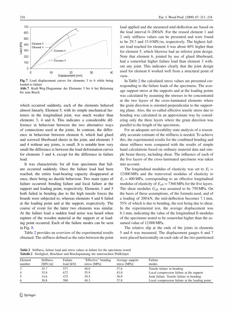
Fig. 7 Load displacement curves for elements 3 to 6 while beingloaded to failureAbb. 7 Kraft-Weg-Diagramme der Elemente 3 bis 6 bei Belastungbis zum Bruch
which occurred suddenly, each of the elements behavedalmost linearly. Element 5, with its simple mechanical fas-teners in the longitudinal joint, was much weaker thanelements 3, 4 and 6. This indicates a considerable dif-ference in behaviour between the two alternative waysof connections used at the joints. In contrast, the differ-ence in behaviour between element 6, which had gluedand screwed fiberboard sheets in the joint, and elements 3and 4 without any joints, is small. It is notable how verysmall the difference is between the load-deformation curvesfor elements 3 and 4, except for the difference in failureload.
It was characteristic for all four specimens that fail-ure occurred suddenly. Once the failure load had beenreached, the entire load-bearing capacity disappeared atonce, there being no ductile behaviour. Two main types offailure occurred: bending failure and local failure at thesupport and loading point, respectively. Elements 3 and 5both failed in bending due to the high tensile forces theboards were subjected to, whereas elements 4 and 6 failedat the loading point and at the support, respectively. Thecourse of event for the latter two elements was similar.At the failure load a sudden loud noise was heard whenrupture of the wooden material at the support or at load-ing point occurred. Each of the failure modes can be seenin Fig. 8.
Table 2 provides an overview of the experimental resultsobtained. The stiffness defined as the ratio between the point
Table 2 Stiffness, failure load and stress values at failure for the specimens testedTabelle 2 Steifigkeit, Bruchlast und Bruchspannung der untersuchten Prufkorper
Element Stiffness Failure “Effective” bending Average support Failurenumber [MN/m] load [kN] stress [MPa] stress [MPa] modes
3 35.7 577 48.0 37.6 Tensile failure in bending4 35.8 672 55.9 43.8 Local compression failure at the support5 14.6 475 39.5 30.9 Joint failure. Tensile failure in bending6 30.8 580 48.3 37.8 Local compression failure at the loading point
load applied and the measured mid-deflection are based onthe load interval 0–200 kN. For the reused element 1 and2 only stiffness values can be presented and were foundto be 29.7 and 33.0 MN/m, respectively. The highest fail-ure load reached for element 4 was about 40% higher thanfor element 5, which likewise had an inferior joint design.Note that element 6, jointed by use of glued fibreboard,had a somewhat higher failure load than element 3 with-out any joint. This indicates clearly that the joint designused for element 6 worked well from a structural point ofview.
In Table 2 the calculated stress values are presented cor-responding to the failure loads of the specimens. The aver-age support stress at the supports and at the loading pointswas calculated by assuming the stresses to be concentratedat the two layers of the cross-laminated elements wherethe grain direction is oriented perpendicular to the support-ing plane. Also, the so-called effective tensile stress due tobending was calculated in an approximate way by consid-ering only the three layers where the grain direction wasparallel to the length of the specimens.
For an adequate serviceability state analysis of a reason-ably accurate estimate of the stiffness is needed. To achievethis, the experimental results for the combined bending andshear stiffness were compared with the results of simplehand calculations based on ordinary material data and sim-ple beam theory, including shear. The influence of each ofthe five layers of the cross-laminated specimens was takeninto account.
The longitudinal modulus of elasticity was set to El =12 000 MPa and the transversal modulus of elasticity toEt = 400 MPa, corresponding to an effective longitudinalmodulus of elasticity of Eeff = 7360 MPa for the five layers.The shear modulus Geff was assumed to be 750 MPa. Onthe basis of these assumptions, of the formula used, and ofa loading of 200 kN, the mid-deflection becomes 7.1 mm,55% of which is due to bending, the rest being due to shear.In the experimental test, the average displacement was6.1 mm, indicating the value of the longitudinal E-modulusof the specimens tested to be somewhat higher than the as-sumed value of 12 000 MPa.
The relative slip at the ends of the joints in elements5 and 6 was measured. The displacement gauges 6 and 7were placed horizontally on each side of the two partitioned
1 3

Eur. J. Wood Prod. (2009) 67: 211–218 217
Fig. 8 Failure modes and location of each for the four elements, bending failure being involved for elements 3 and 5, and failure at the supportand failure close to the load application point for element 4 and element 6, respectivelyAbb. 8 Bruchbilder und Bruchstellen der vier Elemente 3 bis 6; Elemente 3 und 5: Biegebruch Element 4: Bruch am Auflager, Element 6: Bruchim Lasteinleitungsbereich
Fig. 9 The slips measured in the joints of elements 5 and 6, the meas-urements being made at both ends of the respective longitudinal jointAbb. 9 Verschiebung in den Elementen 5 und 6 (an beiden Enden derjeweiligen Verbindung gemessen)
elements 5 and 6, respectively, see Fig. 4. The relative sliphorizontally measured (as absolute values) between the twohalves, can be seen in Fig. 9. The slip for element 5 wasmuch greater than in the case of the glued and screwed con-nections used for element 6 showing further the very lowdegree of stiffness of element 5, which resulted in a muchlarger deformation of the specimen than for the other speci-mens tested, as can be seen in Fig. 7.
6 Conclusion
Testing a number of cross-laminated timber element spe-cimens experimentally with respect to their stiffness and
1 3
218 Eur. J. Wood Prod. (2009) 67: 211–218
strength provided useful results. Two of the specimens werepartitioned into two parts and were then reconnected, twoalternative joining methods being employed. It was shownthat for one of the two jointing alternatives the connectionbetween the joined parts was just as strong and stiff as forthe corresponding elements without a joint. The weaker al-ternative of using only mechanical connectors and a sawnboard as a connecting medium is not to be recommendedsince the resulting strength and the stiffness were much toolow.
The high level of stiffness obtained for the cross-laminated wall elements and the possibility this providedof obtaining sufficiently strong and stiff connections indi-cate the use of cross-laminated timber elements to havea strong stabilising potential in building construction involv-ing timber.
References
Blass HJ, Fellmoser P (2004) Design of Solid Wood Panels with CrossLayers, Proceedings of the WCTE-meeting in Lahti, Finland
Dujic B, Pucelj J, Zarnic R (2004) Study of Innovative Wooden HouseBased on Racking Test of Solid Wall Panels. Proceedings of theCOST-E29 meeting in Florence, Italy
Ellis BR, Bougard AJ (2001) Dynamic testing and stiffness evaluationof a six-storey timber framed building during construction. EngStruct 23(10):1232–1242
Kasal B, Collins MS, Paevere P, Foliente GC (2004) Design modelsof light frame wood buildings under lateral loads. J Struct EngASCE 130(8):1263–1271
Kallsner B, Lam F (1995) Diaphragms and shear walls. In: Holzbau-werke nach Eurocode 5 – STEP 3. Dusseldorf, Germany, p 15/1–15/19
Moosbrugger T, Guggenberger W, Bogensperger T (2006) Cross-Laminated Timber Segments Under Homogeneous Shear – Withand Without Openings. Proceedings of the WCTE-meeting inPortland, USA
1 3