Embed Size (px)
Citation preview
This article was downloaded by: [University of Toronto Libraries]On: 23 November 2014, At: 23:35Publisher: Taylor & FrancisInforma Ltd Registered in England and Wales Registered Number: 1072954 Registeredoffice: Mortimer House, 37-41 Mortimer Street, London W1T 3JH, UK
HVAC&R ResearchPublication details, including instructions for authors andsubscription information:http://www.tandfonline.com/loi/uhvc20
Experimental Study of an AutomobileExhaust Heat-Driven Adsorption Air-Conditioning Laboratory Prototypeby Using Palm Activated Carbon-MethanolLeo Sing Lim a & Mohammad Omar Abdullah ba Energy Research Group Laboratoryb Department of Chemical Engineering and EnergySustainability , Universiti Malaysia Sarawak (UNIMAS) ,Sarawak, MalaysiaPublished online: 22 Feb 2011.
To cite this article: Leo Sing Lim & Mohammad Omar Abdullah (2010) Experimental Study of anAutomobile Exhaust Heat-Driven Adsorption Air-Conditioning Laboratory Prototype by Using PalmActivated Carbon-Methanol, HVAC&R Research, 16:2, 221-231
To link to this article: http://dx.doi.org/10.1080/10789669.2010.10390901
PLEASE SCROLL DOWN FOR ARTICLE
Taylor & Francis makes every effort to ensure the accuracy of all the information (the“Content”) contained in the publications on our platform. However, Taylor & Francis,our agents, and our licensors make no representations or warranties whatsoeveras to the accuracy, completeness, or suitability for any purpose of the Content. Anyopinions and views expressed in this publication are the opinions and views of theauthors, and are not the views of or endorsed by Taylor & Francis. The accuracy ofthe Content should not be relied upon and should be independently verified withprimary sources of information. Taylor and Francis shall not be liable for any losses,actions, claims, proceedings, demands, costs, expenses, damages, and other liabilitieswhatsoever or howsoever caused arising directly or indirectly in connection with, inrelation to or arising out of the use of the Content.
This article may be used for research, teaching, and private study purposes. Anysubstantial or systematic reproduction, redistribution, reselling, loan, sub-licensing,systematic supply, or distribution in any form to anyone is expressly forbidden. Terms

& Conditions of access and use can be found at http://www.tandfonline.com/page/terms-and-conditions
Dow
nloa
ded
by [
Uni
vers
ity o
f T
oron
to L
ibra
ries
] at
23:
35 2
3 N
ovem
ber
2014

VOLUME 16, NUMBER 2 HVAC&R RESEARCH MARCH 2010
221
Experimental Study of an Automobile Exhaust Heat-Driven Adsorption
Air-Conditioning Laboratory Prototype by Using Palm Activated Carbon-Methanol
Leo Sing Lim, PhD Mohammad Omar Abdullah, PhD, CEngMember ASHRAE
Received June 30, 2009; accepted October 4, 2009
Adsorption air-cooling systems powered by waste heat or solar heat can help to reduce the useof ozone-depleting substances, such as chlorofluorocarbons (CFCs) and hydro-chlorofluoro-carbons (HCFCs). In recent years, these systems have faced increasing interest in many fieldsbecause they are quiet, long lasting, inexpensive to maintain, and environmentally friendly. Thispaper presents a laboratory prototype of an automobile adsorption air-conditioning systempowered by exhaust heat, which has been successfully built and tested in the laboratory. Theworking pair used is a locally produced palm-derived activated carbon with methanol. Experi-mental results obtained show that, by having a cycle time of 20 minutes, an average chilled-airtemperature of around 73.0°F (22.6°C) is achieved when the cooling coil temperatures fellbetween 49°F to 58°F (9.5°C to 14.7°C). The coefficient of performance (COP) and specificcooling power (SCP) of this prototype are approximately 0.19 and 614 Btu/hlb (396.6 Wkg–1),respectively.
INTRODUCTIONAir conditioning in an automobile is basically the production of desired indoor air conditions,
independent of the outdoor conditions. However, air-conditioning technology is required toevolve due to the new environmental regulations, notably Montreal Protocol in 1987 and Euro-pean Commission Regulation 2037/2000. These regulations were put in place in response toconcerns about the depletion of the ozone layer and an increase in global warming, which begana phase-out of first chlorofluorocarbons (CFCs) then hydro-chlorofluorocarbons (HCFCs). As aresult, this trend has led to a strong demand for a new air-conditioning technology. Among theproposed air-cooling technologies, the adsorption air-cooling system has shown potential. Theadvantages of this system are that it’s long lasting, has low-cost maintenance, uses non-pollutingrefrigerants, is environmentally friendly, and can be powered by heat or solar waste (Dieng andWang 2001). Unfortunately, no working prototype has been practically run in present automo-biles due to various restrictions, including sizing and cooling capacity limitations. In general, theadsorption cycle can be categorized into two main cycles: the intermittent cycle and the continu-ous cycle. The intermittent cycle seems unsuitable for automobile application because it cannotprovide continuous cooling as needed. Thus, a continuous cycle was adopted in this research tocontinuously produce a cooling effect via two adsorbers (containing four total adsorbent beds)that operate intermittently.
Leo Sing Lim is a research specialist at the Energy Research Group Laboratory and Mohammad Omar Abdullah is aSenior Lecturer at the Department of Chemical Engineering and Energy Sustainability at the Universiti Malaysia Sarawak(UNIMAS), Sarawak, Malaysia.
06_Lim.fm Page 221 Monday, March 1, 2010 9:01 AM
© 2010, American Society of Heating, Refrigerating and Air-Conditioning Engineers, Inc. (www.ashrae.org). Published in HVAC&R Research, (vol. 16 (2) March 2010). For personal use only. Additional reproduction, distribution, or transmission in either print or digital form is not permitted without ASHRAE’s prior written permission.
Dow
nloa
ded
by [
Uni
vers
ity o
f T
oron
to L
ibra
ries
] at
23:
35 2
3 N
ovem
ber
2014
222 HVAC&R RESEARCH
A preliminary study was performed by Suzuki (1993) to elucidate the technological limitsassociated with the application of adsorption cooling systems to automobiles. But while thestudy showed some potential for utilizing this method in vehicle air conditioning, the author per-formed a simulations study only and no experimental work was carried out to verify his claim.Aceves (1996) had carried out an experimental analysis of the applicability of an adsorption sys-tem for electric vehicle air conditioning. The coefficient of performance (COP) of the system(with zeolite and water as a working pair) was approximately 0.28. His studies indicated thatconventional compression air conditioners were superior to adsorption systems due to theirhigher COPs and more compact size. The drawback of using zeolite and water as a working pairis that a very low operating pressure is needed. Meanwhile, Sato et al. (1997) have presented amultiple-stage adsorption air-conditioning system for vehicles. Although the efficiency of themultiple-stage adsorption system was improved, the size of the system also increased and itscontrol system became more complex. Zhang (2000) has described an experimental intermittentadsorption cooling system driven by the waste heat of a diesel engine. Zeolite 13X-water is usedas the working pair and a finned double-tube heat exchanger is used as the adsorber. The COPand specific cooling power (SCP) of the system is 0.38 and 25.7 W/kg, respectively. Wang et al.(2001) have studied an adsorption air conditioning for a bus driven by waste heat fromexhausted gases. The working pair for this system is activated carbon and ammonia with thecooling power of 2.58 kW and a COP of 0.16. The activated carbon is pressurized to a density ofabout 900 kg/m3 in to fit additional adsorbent into the adsorber. The total weight of the twoadsorbers is about 248 kg and occupied about 1.0 m2.
Lu et al. (2004) presented experimental studies on the practical performance of an adsorptionair-conditioning system powered by exhausted heat from a diesel locomotive. The system wasincorporated with one adsorbent bed and utilizes zeolite and water as a working pair to providechilled water for conditioning the air in the driver’s cab of the locomotive. Their experimentalresults showed that the adsorption system is technically feasible and can be applied for space airconditioning. Under typical running conditions, the average refrigeration power ranging from3.0 to 4.2 kW has been obtained. However, this system may not be suitable for automobileapplication due to its size and high regenerative temperature. Inoue et al. (2006) have describedan air-conditioner that uses the cooling water of an internal combustion engine, which includes acompressive refrigerator and an adsorption type refrigerator. The compressive refrigerator isused to control the temperature of the air to be blown into a passenger compartment of the vehi-cle. The adsorbent generates adsorption heat when the adsorbent adsorbs the adsorbate, anddesorbs the adsorbate when the adsorbent is heated by coolant water from the internal combus-tion engine. On the other hand, Henning and Mittelbach (2006) have disclosed an adsorptionheat pump for air conditioning a passenger car. Their system is based on a quasi-continuousoperation of adsorption heat pump with the used of cold and heat accumulators.
In our research work, a laboratory prototype of exhaust heat-driven adsorption air-condition-ing system was designed, built, and tested in laboratory to study the replacement of a conven-tional vapor compression air-conditioning system in automobile. The prototype consists of anovel adsorbers system design, coupled with bioresource material of high adsorptive capacitiesfor present invention application.
CURRENT PROTOTYPEThe current prototype consists of an exhaust heat-driven adsorption air-conditioning system,
which is comprised of adsorbers, flow control modules, an evaporator, a condenser, an expan-sion valve, blowers, and an engine. These adsorbers generally have the same function as themechanical compressor in a conventional vapor-compression system. However, these adsorberscontain adsorptive material and adsorbate as working pairs, instead of using CFCs or HCFCs, to
06_Lim.fm Page 222 Monday, March 1, 2010 9:01 AM
© 2010, American Society of Heating, Refrigerating and Air-Conditioning Engineers, Inc. (www.ashrae.org). Published in HVAC&R Research, (vol. 16 (2) March 2010). For personal use only. Additional reproduction, distribution, or transmission in either print or digital form is not permitted without ASHRAE’s prior written permission.
Dow
nloa
ded
by [
Uni
vers
ity o
f T
oron
to L
ibra
ries
] at
23:
35 2
3 N
ovem
ber
2014

VOLUME 16, NUMBER 2, MARCH 2010 223
generate the cooling effect required by using heat from the exhaust gas. As a result, theseadsorbers are also called “thermal compressors.” These adsorbers are first linked to the con-denser via the flow control module, which consist of a few check valves. The condenser is thenconnected through an expansion valve to the evaporator, which in turn is connected back to theadsorbers. The associated adsorbers, condenser, expansion valve, and evaporator are integratedin a closed-loop operation. The engine, blower, and exhaust passage are integrated in an open-loop operation.
The current prototype exhibits several advantages compared to the conventional compres-sion-based air-conditioning system commonly used in contemporary automobiles, such as:
1. Fuel consumption and unwanted gas emission (such as nitrogen oxides and carbon dioxide)would be reduced as overall engine load required is decreased.
2. It is more environmentally friendly as methanol (which leads to neither ozone depletion norglobal warming) was used as a working fluid compared with conventional refrigerants.
3. A low regeneration temperature (less than 300 oF [150.0 oC]) can be used to power the system.4. It operates using fewer moving parts, necessitates lower maintenance costs, and has a simple
system structure.
Adsorbent and Adsorbate PairIn our research work, the biomass of granular palm-derived activated carbon (Figure 1) and
methanol was used as a working pair. Palm-derived activated carbon (Table 1) was selectedbecause it is locally available, offers a high adsorptive capacity, and is also low cost. Methanol,which has low boiling point of about 148°F (64.5°C), is used since a low regeneration tempera-ture is required for the operation of the adsorption system. Besides, methanol has a high latentheat of vaporization of ~ 473 Btu/lb (1100 kJ/kg), which is essential for increasing the coolingcapacity and reducing the quantity of adsorbate used.
Development of the PrototypeThe most crucial and complex part in this prototype is the adsorbers. CATIA 3D, a graphic
software was used to design the adsorber. The adsorbers were designed in such as way (illustratedin Figure 2) as to maximize the quantity of activated carbon and to improve the heat transfer
Figure 1. SEM image of palm-derived activated carbon.
06_Lim.fm Page 223 Monday, March 1, 2010 9:01 AM
© 2010, American Society of Heating, Refrigerating and Air-Conditioning Engineers, Inc. (www.ashrae.org). Published in HVAC&R Research, (vol. 16 (2) March 2010). For personal use only. Additional reproduction, distribution, or transmission in either print or digital form is not permitted without ASHRAE’s prior written permission.
Dow
nloa
ded
by [
Uni
vers
ity o
f T
oron
to L
ibra
ries
] at
23:
35 2
3 N
ovem
ber
2014

224 HVAC&R RESEARCH
between the adsorbent and exhaust gas. Two identical adsorbers were constructed, each adsorberconsisting of two adsorbent beds Each adsorbent bed was packed with approximately 1.8 lb (0.8kg) of granular palm-activated carbon in a stainless steel net. The dimensions of the adsorbers are1.31 ft (40 cm) in length, 0.66 ft (20 cm) in width, and 0.33 ft (10 cm) in height. Six radial stain-less steel fins symmetrically distributed in the adsorbent bed are employed to intensify heat con-duction. A four-stroke petrol 5HP (3.7 kW) engine was used to supply the heat source requiredduring the regeneration process. The heat from the exhaust gas can reach over 300°F (150.0°C),which was more than enough to operate the prototype. The condenser used is a type ofair-finned-tube aluminum heat exchangers that is attached with a 12V d.c. fan to increase the heatrejection rate. Meanwhile, a hanging type of air-finned-tube aluminum heat exchanger, whichconsists of a cooling coil of 3412 Btu/h (1.0 kW) and two blowers powered by a 12V d.c. motorwith a motor speed controller were integrated to the prototype. The detail design of the completesystem is given in Abdullah and Leo (2008).
Table 1. Properties of the Palm-Derived Activated Carbon
Property Value
Particular shape Granular (size < 0.12 in. or 3.0 mm)
Density 26.90 lb/ft3 or 0.431 g/cm3
Heat of adsorption 774 Btu/lb or 1800 kJ/kg
Iodine number 1180
Total pore volume 13.8–16.6 in3/lb or 0.5–0.6 cm3/g
Surface area 4,882,669–5,370,936 ft2/lb or 1000–1100 m2/g
Moisture (% max) Below 5%
Figure 2. Design of the adsorbers.
06_Lim.fm Page 224 Monday, March 1, 2010 9:01 AM
© 2010, American Society of Heating, Refrigerating and Air-Conditioning Engineers, Inc. (www.ashrae.org). Published in HVAC&R Research, (vol. 16 (2) March 2010). For personal use only. Additional reproduction, distribution, or transmission in either print or digital form is not permitted without ASHRAE’s prior written permission.
Dow
nloa
ded
by [
Uni
vers
ity o
f T
oron
to L
ibra
ries
] at
23:
35 2
3 N
ovem
ber
2014
VOLUME 16, NUMBER 2, MARCH 2010 225
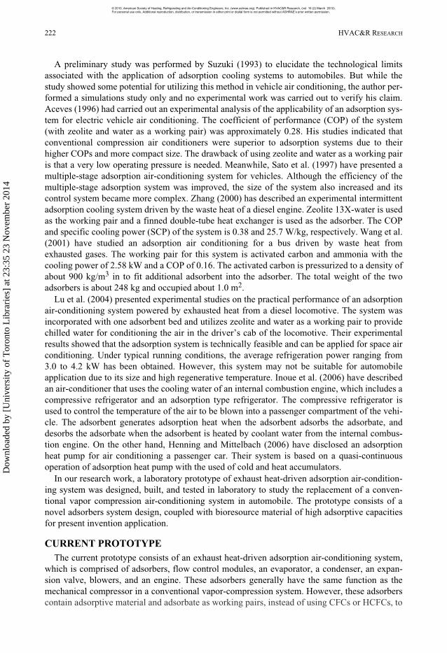
Figure 3 shows the placement and integration of the components in the prototype, which con-sists of two adsorbers, a blower, an evaporator attached to two blowers, a condenser attached toa fan, an expansion valve, four check valves, three three-way valves, an engine, and several pipeconnectors. Before the prototype is ready to be tested, it is evacuated and charged with 24.4 in3
(400 mL) of methanol. The quantity of methanol charged was lower compared to the adsorptioncapacity of activated carbon in order to prevent the activated carbon from becoming saturated,which could reduce the system performance.
Operation of the Prototype
This prototype generally works in two main phases; desorption (regeneration) phase andadsorption phase. Figure 4 shows the schematic diagram of the entire system during the firsthalf-cycle of operation. As shown in this figure, the system begins the process when Adsorber 1is heated by the exhaust gas released from the engine. At the same time, Adsorber 2 is cooled bythe blower. After a few minutes of heating, the adsorber temperature can be raised up to 248°F(120.0°C). The three-way valves (Valve 1 and Valve 2) are used to divert air from the blowerand divert exhaust gas to the adsorbers, respectively, while another three-way valve (Valve 3) isused to bypass the exhaust heat to prevent the adsorbers from overheating. During the heatingprocess, methanol is desorbed and then pressurized by the adsorber. Due to the high-pressuredifference, the check valve (Valve 4) that connected Adsorber 1 to the condenser is automati-cally opened and Valve 5 is closed. The high temperature and pressure methanol vapors are thentransmitted to the condenser. When the methanol vapors touch the cool internal surface of thecondenser, the vapors are condensed to form a lower temperature high-pressure liquid. A checkvalve (Valve 8) was placed near the inlet of the condenser to avoid reversing the process and toprevent methanol liquid from accumulating inside the tube. To increase the heat rejection rate, aten-blade fan was mounted at the back of the condenser.
Figure 3. Prototype setup.
06_Lim.fm Page 225 Monday, March 1, 2010 9:01 AM
© 2010, American Society of Heating, Refrigerating and Air-Conditioning Engineers, Inc. (www.ashrae.org). Published in HVAC&R Research, (vol. 16 (2) March 2010). For personal use only. Additional reproduction, distribution, or transmission in either print or digital form is not permitted without ASHRAE’s prior written permission.
Dow
nloa
ded
by [
Uni
vers
ity o
f T
oron
to L
ibra
ries
] at
23:
35 2
3 N
ovem
ber
2014

226 HVAC&R RESEARCH
As Adsorber 1 is continuously heated, more methanol is desorbed from the adsorbent. Conse-quently, the pressure increased and forces the methanol liquid to travel via an expansion valve(Valve 9). A filter was placed at the inlet of the valve to prevent any dust or impurity fromblocking it, which can cause malfunction of the system. When the high-pressure methanol liquidenters the evaporator, it vaporizes spontaneously due to lower pressure inside the evaporator.When the methanol vaporizes, it absorbs large amounts of heat from cooling space. Thesevapors are then adsorbed by Adsorber 2, low in both pressure and temperature, where Valve 6 isclosed while Valve 7 is opened. In this half cycle of operation, Adsorber 1 became dischargeside while Adsorber 2 acted as suction side to generate cooling effect in the evaporator.
During the second half cycle, exhaust gas was diverted to heat Adsorber 2 (desorption phase)while Adsorber 1 (adsorption phase) was cooled by the blowing air. In this half cycle, Adsorber1 acted as suction side (Valve 4 is closed and Valve 6 is opened) while Adsorber 2 became dis-charge side (Valve 5 is opened and Valve 7 is closed). The temperature of Adsorber 2 increasedand caused the methanol to desorb from the activated carbon. The methanol vapors then traveledto the condenser and condensed. On the other hand, the temperature of Adsorber 1 decreased bythe air blown from the blower. The same processes as the previous half cycle are repeated butnow the methanol vapors from the evaporator is adsorbed by Adsorber 1. As a result, a continu-ously cooling effect was achieved by merely providing means of heating and cooling of theadsorbers intermittently.
Experimental Procedures
The prototype was tested inside an open laboratory, where the exhaust gas was allowed toflow out to the surrounding. A test chamber, made by using Perspex, was built and installed atthe evaporator outlet to reduce the effect of the engine heat and flowing air on the experimentresults. During the test run, K Type thermocouples were used to measure temperature variationof the evaporator, condenser and the engine. Two thermocouples were attached to the evapora-tor, one thermocouple located at the back and another one at the front of the evaporator coil, to
Figure 4. Schematic of the prototype during operation.
06_Lim.fm Page 226 Monday, March 1, 2010 9:01 AM
© 2010, American Society of Heating, Refrigerating and Air-Conditioning Engineers, Inc. (www.ashrae.org). Published in HVAC&R Research, (vol. 16 (2) March 2010). For personal use only. Additional reproduction, distribution, or transmission in either print or digital form is not permitted without ASHRAE’s prior written permission.
Dow
nloa
ded
by [
Uni
vers
ity o
f T
oron
to L
ibra
ries
] at
23:
35 2
3 N
ovem
ber
2014

VOLUME 16, NUMBER 2, MARCH 2010 227
measure the temperature variation of the inlet air and outlet air through the cooling coil. Ther-mocouples were also placed near the inlet and outlet of the condenser to determine the averagecondensation temperature of the methanol vapors, while another thermocouple was located atthe exhaust outlet for measuring exhaust temperature. Besides, thermocouples were used tomeasure the adsorbers temperature at different locations, where average readings were taken. Inaddition, the pressures between the adsorber-condenser and evaporator-adsorber were measuredby using two compound vacuum gauges (range: –1 to +3 bars). A humidity meter was used tomeasure the variation of humidity inside the laboratory before and during the experiments.
Performance EvaluationThe performance of the adsorption cooling system is commonly evaluated using two perfor-
mance factors: the coefficient of performance (COP) and specific cooling power (SCP). In gen-eral, COP is the amount of cooling produced by an adsorption cooling system per unit heatsupplied (Anyanwu 2004; Zhang 2000) as shown below:
(1)
where Qev is the quantity of heat transferred through the evaporator Qde is the quantity of heat adsorbed by the adsorber during the desorption phase
The SCP, on the other hand, is defined as the ratio between the cooling production and thecycle time per unit of adsorbent weight, as given below:
(2)
where tcyc is the cycle time mac is mass of the activated carbon
Since SCP relates to both the mass of adsorbent and the cooling power, it reflects the size of thesystem. For a nominal cooling load, higher SCP values indicate the compactness of the system.
RESULTS AND DISCUSSION
Temperature Profiles of the Prototype A series of experiments have been carried out to determine the best operating temperature for
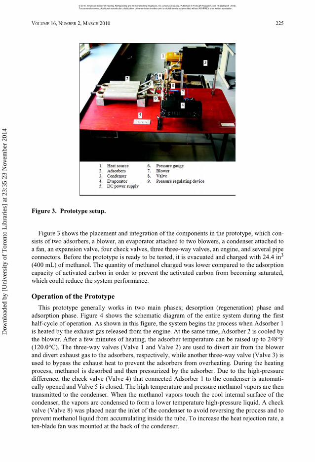
this prototype. Figure 5 presents a simple T-S diagram of the prototype and its design operatingtemperatures. With these operating conditions, the system was operated to show the heat distri-butions profile of the adsorbers (as shown in Figure 6) by using a thermography camera. In thisfigure, the Adsorber 2 was in the desorption phase while Adsorber 1 was in adsorption phase.During the desorption phase, the adsorber was heated by the exhaust heat to an average temper-ature of 257 °F (125°C). At the same time, the other adsorber was cooled by the blowing air andadsorb methanol vapor from the evaporator.
Variation of Temperature with Various Types of Pressure Regulating DevicesTwo common types of pressure regulating devices were tested to determine the most suitable
valve that could provide the lowest cooling temperature in the shortest time, the thermal expansionvalve and orifice tubes (orifice size: 0.012 in. [0.3 mm], 0.016 in. [0.4 mm], 0.020 in. [0.5 mm],and 0.024 in. [0.6 mm]). The initial ambient temperature during all the experiments was controlledaround 84°F (29.0°C) with an initial relative humidity around 85% that was decreased to about
COP Qev Qde=
SCP Qev tcycmac =
06_Lim.fm Page 227 Monday, March 1, 2010 9:01 AM
© 2010, American Society of Heating, Refrigerating and Air-Conditioning Engineers, Inc. (www.ashrae.org). Published in HVAC&R Research, (vol. 16 (2) March 2010). For personal use only. Additional reproduction, distribution, or transmission in either print or digital form is not permitted without ASHRAE’s prior written permission.
Dow
nloa
ded
by [
Uni
vers
ity o
f T
oron
to L
ibra
ries
] at
23:
35 2
3 N
ovem
ber
2014
228 HVAC&R RESEARCH
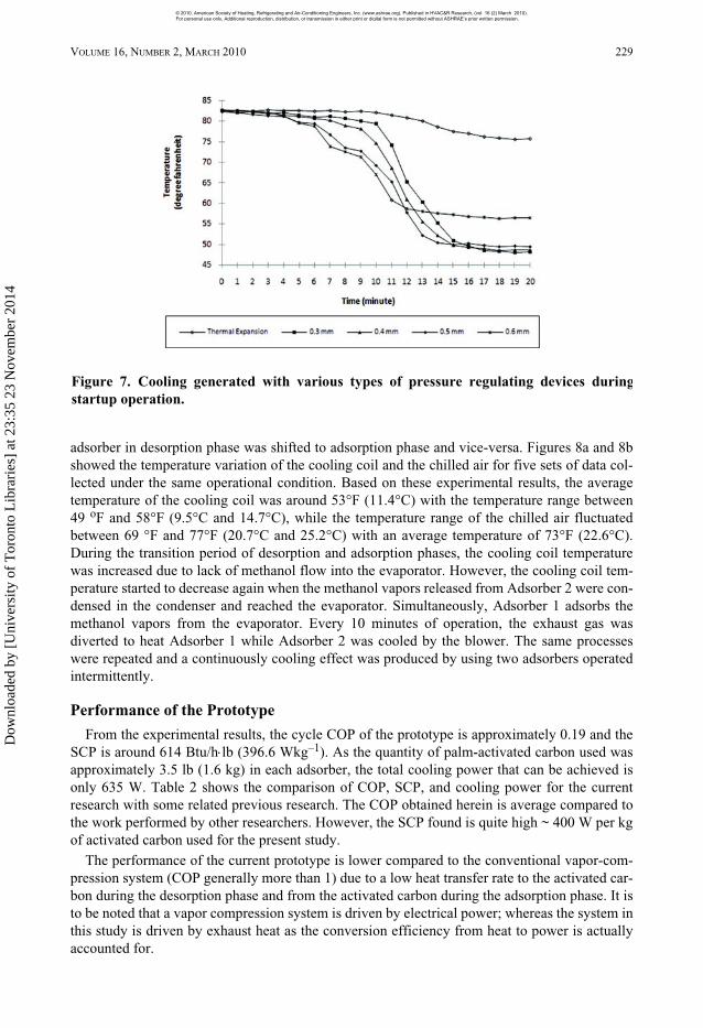
60% during operation. The data gathered was presented in Figure 7, which showed the trend of thecooling coil temperature over time for the first half-cycle during startup operation. Based on thisfigure, the cooling generated in the cooling coil by using a thermal expansion valve was the leastsuccessful compared to orifice tubes. It also showed that the size of the orifice influenced the cool-ing generated and also the time taken to start cooling. Among the four types of orifice tubes, the0.012 in. (0.3 mm) orifice tube produced the highest cooling effect but took the longest timewhereas 0.024 in (0.6 mm) orifice tube produced the lowest cooling effect in shortest time. In orderto increase the system’s efficiency, the cooling temperature must be lowest and the time taken toachieve this cooling must be shortest. As a result, the 0.020 in. (0.5 mm) orifice tube was the bestcompromise between desired cooling effect and low cycle time.
Variation of Temperature during Operations
A series of experiments have been conducted to determine the cycle time of the system, whereit was set to be around 20 minutes per cycle. This means every 10 minutes of operation, the
Figure 5. Simple T-S diagram of the prototype.
Figure 6. Temperature variation of the adsorbers during operation.
06_Lim.fm Page 228 Monday, March 1, 2010 9:01 AM
© 2010, American Society of Heating, Refrigerating and Air-Conditioning Engineers, Inc. (www.ashrae.org). Published in HVAC&R Research, (vol. 16 (2) March 2010). For personal use only. Additional reproduction, distribution, or transmission in either print or digital form is not permitted without ASHRAE’s prior written permission.
Dow
nloa
ded
by [
Uni
vers
ity o
f T
oron
to L
ibra
ries
] at
23:
35 2
3 N
ovem
ber
2014
VOLUME 16, NUMBER 2, MARCH 2010 229
adsorber in desorption phase was shifted to adsorption phase and vice-versa. Figures 8a and 8bshowed the temperature variation of the cooling coil and the chilled air for five sets of data col-lected under the same operational condition. Based on these experimental results, the averagetemperature of the cooling coil was around 53°F (11.4°C) with the temperature range between49 oF and 58°F (9.5°C and 14.7°C), while the temperature range of the chilled air fluctuatedbetween 69 °F and 77°F (20.7°C and 25.2°C) with an average temperature of 73°F (22.6°C).During the transition period of desorption and adsorption phases, the cooling coil temperaturewas increased due to lack of methanol flow into the evaporator. However, the cooling coil tem-perature started to decrease again when the methanol vapors released from Adsorber 2 were con-densed in the condenser and reached the evaporator. Simultaneously, Adsorber 1 adsorbs themethanol vapors from the evaporator. Every 10 minutes of operation, the exhaust gas wasdiverted to heat Adsorber 1 while Adsorber 2 was cooled by the blower. The same processeswere repeated and a continuously cooling effect was produced by using two adsorbers operatedintermittently.
Performance of the Prototype
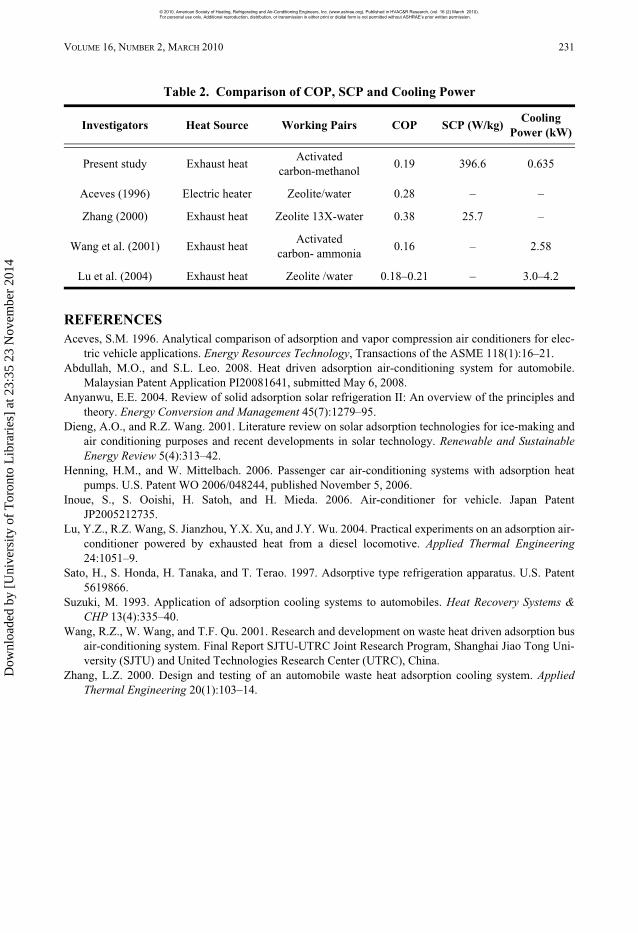
From the experimental results, the cycle COP of the prototype is approximately 0.19 and theSCP is around 614 Btu/hlb (396.6 Wkg–1). As the quantity of palm-activated carbon used wasapproximately 3.5 lb (1.6 kg) in each adsorber, the total cooling power that can be achieved isonly 635 W. Table 2 shows the comparison of COP, SCP, and cooling power for the currentresearch with some related previous research. The COP obtained herein is average compared tothe work performed by other researchers. However, the SCP found is quite high ~ 400 W per kgof activated carbon used for the present study.
The performance of the current prototype is lower compared to the conventional vapor-com-pression system (COP generally more than 1) due to a low heat transfer rate to the activated car-bon during the desorption phase and from the activated carbon during the adsorption phase. It isto be noted that a vapor compression system is driven by electrical power; whereas the system inthis study is driven by exhaust heat as the conversion efficiency from heat to power is actuallyaccounted for.
Figure 7. Cooling generated with various types of pressure regulating devices duringstartup operation.
06_Lim.fm Page 229 Monday, March 1, 2010 9:01 AM
© 2010, American Society of Heating, Refrigerating and Air-Conditioning Engineers, Inc. (www.ashrae.org). Published in HVAC&R Research, (vol. 16 (2) March 2010). For personal use only. Additional reproduction, distribution, or transmission in either print or digital form is not permitted without ASHRAE’s prior written permission.
Dow
nloa
ded
by [
Uni
vers
ity o
f T
oron
to L
ibra
ries
] at
23:
35 2
3 N
ovem
ber
2014

230 HVAC&R RESEARCH
CONCLUSION
A working prototype of exhaust heat-driven adsorption air-conditioning system usingpalm-derived activated carbon-methanol has been built, commissioned and laboratory tested.The experimental results showed the employment of adsorption technologies in automobileair-conditioner are feasible and promising; however, there is a need to further enhance the effi-ciency and the associated control system for effective on-the-road application.
ACKNOWLEDGMENT
The present study is supported by the Universiti Malaysia Sarawak’s Special Project GrantNo. DI/04/2007/(04). The first author would like to thank the Ministry of Science, Technology,and Innovation of Malaysia for the MOSTI fellowship award. Both authors would like to thankall staff for their continuous encouragements throughout this project.
Figure 8. Variation of temperatures: (A) cooling coil and (B) chilled air duringsteady-state operations, respectively.
06_Lim.fm Page 230 Monday, March 1, 2010 9:01 AM
© 2010, American Society of Heating, Refrigerating and Air-Conditioning Engineers, Inc. (www.ashrae.org). Published in HVAC&R Research, (vol. 16 (2) March 2010). For personal use only. Additional reproduction, distribution, or transmission in either print or digital form is not permitted without ASHRAE’s prior written permission.
Dow
nloa
ded
by [
Uni
vers
ity o
f T
oron
to L
ibra
ries
] at
23:
35 2
3 N
ovem
ber
2014
VOLUME 16, NUMBER 2, MARCH 2010 231
REFERENCES Aceves, S.M. 1996. Analytical comparison of adsorption and vapor compression air conditioners for elec-
tric vehicle applications. Energy Resources Technology, Transactions of the ASME 118(1):16–21.Abdullah, M.O., and S.L. Leo. 2008. Heat driven adsorption air-conditioning system for automobile.
Malaysian Patent Application PI20081641, submitted May 6, 2008.Anyanwu, E.E. 2004. Review of solid adsorption solar refrigeration II: An overview of the principles and
theory. Energy Conversion and Management 45(7):1279–95.Dieng, A.O., and R.Z. Wang. 2001. Literature review on solar adsorption technologies for ice-making and
air conditioning purposes and recent developments in solar technology. Renewable and SustainableEnergy Review 5(4):313–42.
Henning, H.M., and W. Mittelbach. 2006. Passenger car air-conditioning systems with adsorption heatpumps. U.S. Patent WO 2006/048244, published November 5, 2006.
Inoue, S., S. Ooishi, H. Satoh, and H. Mieda. 2006. Air-conditioner for vehicle. Japan PatentJP2005212735.
Lu, Y.Z., R.Z. Wang, S. Jianzhou, Y.X. Xu, and J.Y. Wu. 2004. Practical experiments on an adsorption air-conditioner powered by exhausted heat from a diesel locomotive. Applied Thermal Engineering24:1051–9.
Sato, H., S. Honda, H. Tanaka, and T. Terao. 1997. Adsorptive type refrigeration apparatus. U.S. Patent5619866.
Suzuki, M. 1993. Application of adsorption cooling systems to automobiles. Heat Recovery Systems &CHP 13(4):335–40.
Wang, R.Z., W. Wang, and T.F. Qu. 2001. Research and development on waste heat driven adsorption busair-conditioning system. Final Report SJTU-UTRC Joint Research Program, Shanghai Jiao Tong Uni-versity (SJTU) and United Technologies Research Center (UTRC), China.
Zhang, L.Z. 2000. Design and testing of an automobile waste heat adsorption cooling system. AppliedThermal Engineering 20(1):103–14.
Table 2. Comparison of COP, SCP and Cooling Power
Investigators Heat Source Working Pairs COP SCP (W/kg)Cooling
Power (kW)
Present study Exhaust heatActivated
carbon-methanol0.19 396.6 0.635
Aceves (1996) Electric heater Zeolite/water 0.28 – –
Zhang (2000) Exhaust heat Zeolite 13X-water 0.38 25.7 –
Wang et al. (2001) Exhaust heatActivated
carbon- ammonia0.16 – 2.58
Lu et al. (2004) Exhaust heat Zeolite /water 0.18–0.21 – 3.0–4.2
06_Lim.fm Page 231 Monday, March 1, 2010 9:01 AM
© 2010, American Society of Heating, Refrigerating and Air-Conditioning Engineers, Inc. (www.ashrae.org). Published in HVAC&R Research, (vol. 16 (2) March 2010). For personal use only. Additional reproduction, distribution, or transmission in either print or digital form is not permitted without ASHRAE’s prior written permission.
Dow
nloa
ded
by [
Uni
vers
ity o
f T
oron
to L
ibra
ries
] at
23:
35 2
3 N
ovem
ber
2014