Embed Size (px)
Citation preview

Subject to change ndash October 2006 ndash 1MA110_1E
Rohde amp Schwarz products Vector Signal Generator RampSregSMU200A Vector Signal Analyzer RampSregFSQ26 Power Meter RampSregNRP Power Meter Sensor RampSregNRP-Z11
Experimental Study of 3G Signal Interaction in Nonlinear Downlink RAN Transmitters
Application Note 1MA110
Abstract - While RF communication signal distortions in nonlinear transmission paths have been predicted theoretically and studied experimentally for various signals it is interesting to examine a wideband nonlinear system reaction to a wideband 3G signal and a narrowband 2G signal Research and testing have demonstrated that while most vital signal parameters remain within the limits specified by applicable standards even if composite signal power approaches specified maximum power a relatively high level of spurious emissions caused by cross- and intermodulation can result To avoid degrading both existing and new systems this and other signal quality issues must be considered when designing and deploying multitechnology systems
Reprint of Igor A Chugunov Aleksey A Kurochkin Alex M Smirnov EXPERIMENTAL STUDY OF 3G SIGNAL INTERACTION IN NONLINEAR DOWNLINK RAN TRANSMITTERS Bechtel Telecommunications Technical Journal June 2006 bull Volume 4 Number 2 With friendly permission of Bechtel Corporation httpwwwbechteltelecomscom
1MA110_1E 2 Rohde amp Schwarz
Contents 1 Abstract 3 2 Introduction 3 3 Background 4 4 Measurements of 3G Signal Parameters in DAS Fed By Signal Mixture 5 5 Cross-Modulation Study 6 6 Intermodulation Study Adjacent and Alternate Channel Levels 8 7 Modulation Accuracy Study 9 8 Network Design Implications 10 9 Conclusions 12 10 Abbreviations and Terms 13 11 References 14 12 Biographies 15 13 Additional Information 16 14 Ordering Information 17
Reprint of Igor A Chugunov Aleksey A Kurochkin Alex M Smirnov
EXPERIMENTAL STUDY OF 3G SIGNAL INTERACTION IN NONLINEAR DOWNLINK RAN TRANSMITTERS
Bechtel Telecommunications Technical Journal June 2006 bull Volume 4 Number 2
With friendly permission of Bechtel Corporation httpwwwbechteltelecomscom
TRADEMARKS
3GPP is a trademark of the European Telecommunications Standards Institute (ETSI) in France and other jurisdictions
Introduction
1MA110_1E 3 Rohde amp Schwarz
1 Abstract
While RF communication signal distortions in nonlinear transmission paths have been predicted theoretically and studied experimentally for various signals it is interesting to examine a wideband nonlinear system reaction to a wideband 3G signal and a narrowband 2G signal Research and testing have demonstrated that while most vital signal parameters remain within the limits specified by applicable standards even if composite signal power approaches specified maximum power a relatively high level of spurious emissions caused by cross- and intermodulation can result To avoid degrading both existing and new systems this and other signal quality issues must be considered when designing and deploying multitechnology systems
2 Introduction
This paper presents the experimental study of signal distortion in third generation (3G) radio access network (RAN) downlinks caused by nonlinearity The common nonlinear element in downlink transmitters is the power amplifier (PA) however in a distributed antenna system1 (DAS) the up and down converters and digitizers may be factors as well Most contemporary base station (BS) transmitters and DASs use multichannel PAs which only increase nonlinear distortion The amplification of several signals leads to cross-modulation in addition to other well-known phenomena such as saturation and intermodulation (IM) Cross-modulation is a fundamental performance-limiting factor that is responsible for co-site interference and jamming [1] It is especially important to evaluate cross-modulation and accompanying nonlinear phenomena in wideband nonlinear radio frequency (RF) systems such as DASs which may distribute and amplify the communication signals of various technologies
1 Distributed antenna systems or DASs have been widely implemented in state-of-the-art cellular communication systems to cover spots with poor or no coverage Such spots can occur within the cell coverage area due to shadowing building attenuation terrain or clutter features etc A DAS usually consists of a central unit or hub and several radio heads interconnected by cables In a typical case the hub is fed by the signal(s) from a BS while radio heads are distributed across the area of coverage (indoor or outdoor installation) A DAS can be analog or digital ie the communications between hub and radio head via cable can be in analog or digital format Digital DASs offer several advantages including two especially desirable features precisely controlled signal delays between hub and radio heads and great tolerance to cable attenuation
Background
1MA110_1E 4 Rohde amp Schwarz
3 Background
Major cellular and personal communication system (PCS) carriers in the US have implemented global system for mobile communications (GSM) technology (along with general packet radio service [GPRS] or enhanced data rates for GSM evolution [EDGE] data service) and are adding universal mobile telecommunication system (UMTS) wideband code division multiple access (WCDMA) service to their networks The downlink signals of these technologies are likely to be mixed at low power levels and then amplified in one multichannel amplifier Similar multichannel amplification (along with other signal transformation) takes place in a multicarrier DAS which is widely used to provide coverage in complicated areas Consequently the problem of signal interaction in the case of multichannel multitechnology amplification becomes significant This paper focuses on the practical aspects of overlay deployment of WCDMA on a GSM network and specifically on the results of co-amplification and co-processing of the two signals at the same site in the same transmission path
Nonlinear distortions of communication signals are well known and have been studied widely References cited here focus on the study of wideband signal (CDMA and the like) behavior in nonlinear systems In a theoretical and experimental study of cross-modulation in multichannel amplifiers [1] cross-modulation was examined for CDMA Interim Standard 95 (IS-95) signals in the presence of a single tone being offset in frequency Based on computer simulation confirmed by measurements it was shown that cross-modulation manifested itself as two band-limited spectral components centered at the tone frequency and at the CDMA carrier frequency The distortions of a single WCDMA signal were examined in [2] and distortion and interaction of two WCDMA signals were analyzed in [3] The case of a single CDMA (IS-95) signal was studied in [4] Although [5] examined the performance of a WCDMA 1900 MHz system in the presence of a GSM interferer this study was aimed at evaluating high-level system parameters such as coverage and capacity Moreover the GSM interferer was assumed to have originated at a neighboring cell and no comparable data was presented in [5] Therefore it was necessary to collect measurements from a nonlinear system In this case extensive measurements were taken of multitechnology (GSM and WCDMA) signals in a DAS
Measurements on 3G Signal Parameters
1MA110_1E 5 Rohde amp Schwarz
4 Measurements of 3G Signal Parameters in DAS Fed By Signal Mixture
Based on the references cited above the following metrics were chosen in this paper to characterize nonlinear distortions (a) the level changes of adjacentalternate channels and (b) modulation accuracy degradation In addition cross modulation was qualitatively characterized The observed nonlinear signal impairment was not attributed to a specific component of the DAS (amplifier down converter etc)
The measurements presented here were taken using various Rohde amp Schwarz devices an SMU200A vector signal generator an FSQ26 vector signal analyzer (which can also operate as a spectrum analyzer) and an NRP-Z11 power meter The input signals for the transmission device to be studied were forward link GSM and frequency duplex division (FDD) WCDMA signals imitated by the SMU200A vector signal generator GSM signals contained all eight active time slots five were full-rate voice slots and three were EDGE slots (It should be noted that the proportion of EDGE and GSM slots was arbitrary The presence of one or more EDGE time slots affects the signal spectrum however the particular ratio of EDGE to GSM slots does not noticeably affect the systems response) The WCDMA signal was a 384 Mchipssec 3G signal with a spreading factor of 256 in the pilot channel loaded with 64 physical channels each with a 15 kssec rate
Signal impairments were measured with the FSQ26 vector signal analyzer using its firmware options for Third Generation Partnership Project (3GPPtrade)-compliant signals For spectrum scans resolution bandwidth (RBW) was set to 30 kHz with video bandwidth (VBW) of 100 kHz the power reference level and frequency scan parameters were adjusted in accordance with output signal characteristics The composite output power was monitored by the power meter Figure 1 depicts the measurement setup
Figure 1 Measurement Setup Diagram
Measurements on 3G Signal Parameters
1MA110_1E 6 Rohde amp Schwarz
A typical multichannel DAS having one central unit and one remote radio unit interconnected by digital cable was used as a subject of study It operated in the North America PCS frequency band (1900 MHz) Only the forward path (downlink) of this wideband system was investigated
As a part of system baselining common measurements included a 1 dB compression point a third-order intermodulation intercept point (IIP3) and input saturation power measurements The measurements were needed to define the maximum output power of the PA radio unit for a continuous wave (CW) signal Later in this paper the maximum output power value is used as a reference point for powerspectrum measurements and all signal parameters are evaluated relative to power backoff (BO) which is the difference between current composite output power and maximum output power for a sine wave signal This kind of presentation of results is more general than a simple relationship to output power It should be noted that the maximum power value obtained in the evaluation strictly equals the maximum composite power specified by the manufacturer
5 Cross-Modulation Study Cross-modulation was studied for a mix of GSM and WCDMA signals with various GSM-to-WCDMA mean power ratios The spectral diagrams in Figures 2 and 3 show two cases PGSMPWCDMA = 15 dB and PGSMPWCDMA = 0 dB with BO being a parameter In these diagrams relative power value is defined as output power less maximum output power Signal carrier frequencies were 10 MHz apart and were placed in different sub-bands of the 1900 MHz PCS frequency band
Figures 2 and 3 reflect the whole spectrum of nonlinear phenomena The WCDMA spectrum demonstrated regrowth when IM and cross-modulation products appeared around the fundamental WCDMA spectrum The cross-modulation products also showed up around the narrow-band GSM spectrum and third-order IM products appeared at 10 MHz below the GSM carrier spectrum and at 10 MHz above the WCDMA carrier spectrum
As expected the cross-modulation level was inversely related to power BO
The fact that the products of GSM-to-WCDMA cross-modulation were centered around the GSM spectrum ie in a sub-band other than that occupied by the WCDMA signal is important At the same time IM products were observed in yet another sub-band In other words transmitter spurious emissions (in the form of nonlinear products) polluted neighboring sub-bands of the forward 1900 MHz band Figure 4 shows the relative power level of IM products in upper neighboring sub-bands versus power BO with PGSMPWCDMA being a parameter
Cross Modulation Study
1MA110_1E 7 Rohde amp Schwarz
Figure 2 Output Spectrum PGSMPWCDMA = 15 dB
Figure 3 Output Spectrum PGSMPWCDMA = 0 dB
Figure 4 Relative IM Power Versus Power BO
Intermodulation Study
1MA110_1E 8 Rohde amp Schwarz
6 Intermodulation Study Adjacent and Alternate Channel Levels In the same signal mix levels of adjacent channel leaking ratio (ACLR) for WCDMA channels and alternate channel power ratio (AltCPR) for GSM channels were evaluated While ACLR is defined in the respective 3GPP specification [6] no definition of either adjacent or alternate channels appears in the GSM 3GPP specification for transmitters [7] Instead an emission spectrum mask is defined for GSM signals For this paper an alternate channel level with an absolute frequency offset value between 400 kHz and 600 kHz was chosen to characterize IM distortion of a GSM signal The GSM 3GPP specification for transmitters [7] states that the level of this channel must be -60 dBc or less Figures 5 and 6 show neighboring channel levels for both WCDMA and GSM signals with the PGSMPWCDMA ratio being a parameter
Figure 5 WCDMA ACLR Versus Power BO
Figure 6 GSM ACLR Versus Power BO
Intermodulation Study
1MA110_1E 9 Rohde amp Schwarz
The WCDMA ACLR level remains within the range specified in [6] even in the worst case (PGSMPWCDMA = 0 dB power BO = 1 dB) The ACLR level just approaches the value of -33 dBc specified in [6] At the same time the GSM alternate channel level easily rises above the value specified in [7] as soon as power BO decreases to 7 dB or less (assuming roughly equal mean powers for both signals)
7 Modulation Accuracy Study
For GSM phase error measurements did not reveal any substantial dependence on power BO or power ratio Phase error values remained well below the level specified in [7] even in the worst case
Modulation accuracy indicators for the WCDMA signal demonstrated a different behavior These indicators exhibited degradation as power BO decreased Figures 7 and 8 show the dependence of three major accuracy indicators (peak code domain error [PCDE] error vector magnitude [EVM] and Rho) on power BO
Measurements showed that modulation accuracy stayed within the limits specified by [6]
Figure 7 PCDE and EVM Versus Power BO
Modulation Accuracy Study
1MA110_1E 10 Rohde amp Schwarz
Figure 8 Rho Versus Power BO
8 Network Design Implications
The use of nonlinear devices in the downlink path leads to elevated levels of spurious emissions as well as to an increase in neighboring channel levels Such emissions can cause unwanted interference with the signals of other systems either through overlapping coverage or by being amplified in the same downlink path (except for a sole radiator in an isolated area such as a single DAS radio head within the building) Therefore steps need to be taken at the network planning stage to eliminate interference
When performing link budget and expected coverage radius calculations the network planner should properly identify the allowable composite output power of the PA An amplifier should not be driven to the maximum power specified for a CW signal This is why attention must be paid to the type of maximum output power stated in the manufacturers specifications2 It is important to distinguish between statements of (a) maximum CW power and (b) maximum mean WCDMA power
In case (a) the maximum composite power of all signals in the mix (taking into account future RF channel addition) must be at least 7 dB less than that specified by the manufacturer For case (b) the stated power value should be used as a maximum composite of all signals (even if some signals in the mix are GSM) Such an approach although somewhat conservative allows interference to be eliminated reduces the noise floor level and only negligibly degrades the modulation accuracy indicators in the downlink
2 Brief Internet research on six major amplifierDAS manufacturers by the authors showed that a wide variety of power values exists maximum power for sine wave maximum power for one or more WCDMA signals maximum power for GSM signals and even all of these values for one product None of the manufacturers provided data for signal mix however
Network Design Implications
1MA110_1E 11 Rohde amp Schwarz
A simplified link budget calculation for a known CW power output is given in Table 1 In this hypothetical example a DAS with a maximum CW output power of 30 dBm (0 dBW) was intended to radiate two signals with equal mean power Note that the maximum output power per radio channel was determined by taking power BO into account
RX BAND FREQUENCIES (MHZ)
BSDAS
1850
1865
SU
1830
1845
FORWARD LINK REVERSE LINK
BSDAS Antenna Gain (dBd) 105 SU Antenna Gain (dBd) 0
Max Amplifier Output CW Power (dBW) 0 Amplifier Output Max (W) 02
Power BO (dB) 7
Number of RF ChannelsAntenna 2
Max Amplifier OutputChannel (dBW) -10
BSDAS to Antenna Cable Run (m) 6 SU to Antenna Cable Run (m) 0
SU Diversity Gain (dB) 00 BSDAS Diversity Gain (dB) 00
BSDAS Receive Sensitivity (dBm) -105 SU Receive Sensitivity (dBm) -105
LINK BUDGET CALCULATION AREA
Central Frequency for Calibration (MHz) 1890 1890
BSDAS RF Cable Loss (dB) 064 SU RF Cable Loss (dB) 0
FW Max Allowable Path Loss (dB) 1349 RV Max Allowable Path Loss (dB) 1385
Suggested Amplifier OutputChannel (dBW) -10
Suggested Amplifier OutputChannel (W) 01
Balanced Model ERP (dBm) 299 System ERP (dBm) 299
Balanced Model ERP (W) 1 System ERP (W) 1
Balanced Link (dBm) 1349
Table 1 Link Budget Calculation - 30 dBm maximum CW Output Power
Conclusions
1MA110_1E 12 Rohde amp Schwarz
9 Conclusions
Signal interaction and signal parameter degradation were experimentally studied for the GSMWCDMA signal mix that was processed and amplified by the DAS sample The study showed that when power BO decreased below 7 dB most of the signal quality metrics degraded
Nonetheless the metrics were still within the limits defined by the respective recommendations in [6] and [7] One exception however was the AltCPR for GSM signals If GSM and WCDMA mean powers were roughly equal and BO fell below 7 dB the alternate channel level exceeded the value specified in [7]
Another phenomenon to be considered is power leakage into neighboring sub-bands caused by cross- and intermodulation For signal co-amplification in various sub-bands by a DAS (the most likely use of a DAS) such leakage might cause serious interference problems To avoid the degradation of both existing and new systems these signal quality and interference issues must be taken into account when designing and deploying multitechnology systems
These manifestations of nonlinearity have direct implications for link budget calculations in the network planning process if a multichannel PA is intended to amplify a GSMWCDMA signal mix In determining downlink output power the PA must not be driven to the maximum power specified for a CW signal Instead the composite mean power of all signals to be amplified must be at least 7 dB less than the maximum specified power Under this condition the system will not cause harmful interference in either occupied or neighboring sub-bands
As a follow-on to the study of possible nonlinear communication signal distortions future research steps might focus on a theoretical and experimental examination of the downlink performance in cellular or PCS networks The presence of nonlinear products in the BS or DAS emissions reduces the signal-to-(interference + noise) ratio and could degrade vital system parameters such as coverage interference level probability of successful call setup and dropped calls The study should evaluate the possible dependence between system performance and equipment nonlinearity
A similar study of uplink performance would also be valuable
Abbreviations and Terms
1MA110_1E 13 Rohde amp Schwarz
10 Abbreviations and Terms
3G 3rd generation (of mobile communication systems)
3GPP 3rd Generation Partnership Project
ACLR Adjacent Channel Leaking Ratio (defined for WCDMA)
AltCPR Alternate Channel Power Ratio (for GSM)
BO Power Back-Off
CDMA Code Division Multiple Access system
CW Continuous Wave (sine wave signal)
DAS Distributed Antenna System
dB Decibel (logarithmic ratio of the two values)
dBc Power level of interfering signal in relation to carrier power
dBd Unit of antenna gain measurement in relation to the gain of dipole antenna
dBm Unit of power measurement in relation to 1 mW
dBW Unit of power measurement in relation to 1 W
EDGE Enhanced Data Global Evolution for GSM
EVM Error Vector Magnitude
ERP Effective Radiated Power
FDD Frequency Division Duplex
FW Forward path (from base station to phone) in cellular network same as downlink
GPRS General Radio Packet Service
GSM Global System for Mobile communications
IIP3 Input Intermodulation Point of 3rd order
IM Intermodulation
IS-95 Interim Standard no 95 describing CDMA communication system
MHz Megahertz (frequency measurement unit)
PA Power Amplifier
PCDE Peak Code Domain Error
PCS Personal Communication System
RAN Radio Access Network
RBW Resolution Band Width (in spectrum analysis)
RF Radio Frequency
RV Reverse path (from phone to base station) in cellular networks same as uplink
Abbreviations and Terms
1MA110_1E 14 Rohde amp Schwarz
SU Subscriber Unit
UMTS Universal Mobile Telecommunication System
VBW Video Band Width (in spectrum analysis)
WCDMA Wideband Code Division Multiple Access system
11 References [1] K M Gharaibeh and M B Steer Characterization of cross modulation in multi-channel amplifiers using a statistically based behavioral modeling technique IEEE Trans on Microwave Theory and Techniques vol 51 No 12 2003 pp 2434-2444
[2] A Springer T Frauscher B Adler D Pimingsdorfer R Weigel Effects of nonlinear amplifier distortions on UMTS transmitter system performance Proc of the 2000 European Conf on Wireless Technology (ECWT) Oct 2000 Paris France pp159- 162 ISBN 0-86213-217-7
[3] K M Gharaibeh and M B Steer Modeling distortion in multi-channel communication systems IEEE Trans on Microwave Theory and Techniques vol 53 No 5 May 2005 pp 1682-1692
[4] K M Gharaibeh K G Gard and M B Steer Accurate estimation of digital communication system metrics - SNR EVM and in a nonlinear amplifier environment 64th Auto RF Tech Group Conf Orlando Florida Dec 2004
[5] H Holma and F Velez Performance of WCDMA1900 in the presence of uncoordinated narrow-band GSM interference Vehicular Technology Conference 2002 Proceedings VTC 2002-Fall 2002 IEEE 56th
[6] 3GPP TS 25143 V620 (2004-09) 3rd Generation Partnership Project Technical Specification Group Radio Access Network UTRA repeater conformance testing (Release 6) 3GPP Publication
[7] 3GPP TS 1121 V890 (2003-06) 3rd Generation Partnership Project Technical Specification Group GSMEDGE Radio Access Network Base Station System (BSS) equipment specification Radio aspects (Release 1999) 3GPP Publication
Biographies
1MA110_1E 15 Rohde amp Schwarz
12 Biographies
Igor Chugunov is currently a senior engineer in the Bechtel Telecommunications Training Demonstration and Research (TDR) Laboratory in Frederick Maryland He is experienced in wireless network design and optimization as well as in software and hardware testing His engineering background gives him both theoretical and practical knowledge of wireless access technologies
Before joining Bechtel Igor was a senior RF engineer with Cingular Wireless and Hughes Network Systems where he designed radio access networks for data and voice communication
Igor has an MSEECS degree from Kazan Tupolev State Technical University Russia
Aleksey Kurochkin executive director of Site Development and Engineering for Bechtel Telecommunications manages the Network Planning and Site Acquisition departments He is responsible for process and team integration and oversees the functional operations of more than 300 telecommunications engineers specialists and managers Aleksey is also a member of Bechtels Chief Engineering Committee Global Technology Team and BTTJ Editorial Council
Formerly Aleksey was senior director Network Planning in Bechtels Telecommunications Technology group which he originated He also introduced the Six Sigma continuous improvement program to this group Aleksey is experienced in international telecommunications business management and network implementation and his engineering and marketing background gives him both theoretical and hands-on knowledge of most wireless technologies
Before joining Bechtel Aleksey established an efficient multiproduct team at Hughes Network Systems focused on RF planning and system engineering In addition to his North American experience he has also worked in Russia and the CIS
Aleksey has an MSEECS degree in Automatic Telecommunications from Moscow Technical University of Communications and Informatics Russia
Biographies
1MA110_1E 16 Rohde amp Schwarz
Alex Smirnov is currently a test engineer in the Bechtel Telecommunications Training Demonstration and Research (TDR) Laboratory in Frederick Maryland He conducts tests and prepares test reports for telecommunications equipment He has also performed DAS testing to demonstrate product compliance with functional specifications for Cingular Wireless Earlier as a network planning engineer he planned and designed an FTTP project for Maryland and Delaware
Before joining Bechtel in 2004 Alex was an electronic engineer at Technology Device International Inc and Re-Certify Inc He has over 10 years of information technology experience in all areas of life-cycle program development including analysis design maintenance support and testing of various systems and platforms
Alex holds a masters degree in Science and Optical Engineering from Moscow State University Russia In addition he has a bachelors degree in Financial Management from the Russian Academy of Management Moscow
13 Additional Information This Application Note is a reprint of
Igor A Chugunov Aleksey A Kurochkin Alex M Smirnov
EXPERIMENTAL STUDY OF 3G SIGNAL INTERACTION IN NONLINEAR DOWNLINK RAN TRANSMITTERS
Bechtel Telecommunications Technical Journal June 2006 bull Volume 4 Number 2
With friendly permission of Bechtel Corporation
httpwwwbechteltelecomscom
Please send any comments or suggestions about this article to
TM-Applicationsrsdrohde-schwarzcom
Ordering Information
1MA110_1E 17 Rohde amp Schwarz
14 Ordering Information
Name Description Ordering number
Vector Signal Generator RampS
reg SMU200A 1141200502
RampSreg
SMU-B102 RF Path A 100 kHz to 22 GHz 1141850302
RampSreg
SMU-B103 RF Path A 100 kHz to 3 GHz 1141860302
RampSreg
SMU-B104 RF Path A 100 kHz to 4 GHz 1141870302
RampSreg
SMU-B106 RF Path A 100 kHz to 6 GHz 1141880302 RampS
reg SMU-B202 RF Path B 100 kHz to 22 GHz 1141940002
RampSreg
SMU-B103 RF Path B 100 kHz to 3 GHz 1141950002 RampS
reg SMU-B10 Baseband with ARB (64 Msamples) 1141700702
RampSreg
SMU-B13 Baseband Main Module 1141800302 RampS
reg SMU-K42 Digital Standard 3GPP FDD 1160790902
RampSreg
SMU-K43 3GPP Enhanced Tests 1160966002 Signal Analyzer and Options RampS
reg FSQ3 20 Hz to 36 GHz 1155500103
RampSreg
FSQ8 20 Hz to 8 GHz 1155500108
RampSreg
FSQ26 20 Hz to 265 GHz 1155500126
RampSreg
FS-K72 Application Firmware 3GPP-FDD BTS Transmitter Test
1154700002
For additional information about signal generators and spectrum analysers see the Rohde amp Schwarz website wwwrohde-schwarzcom
ROHDE amp SCHWARZ GmbH amp Co KG Muumlhldorfstraszlige 15 D-81671 Muumlnchen Postfach 80 14 69 D-81614 Muumlnchen
Tel (089) 4129 -0 Fax (089) 4129 - 13777 Internet httpwwwrohde-schwarzcom
This application note and the supplied programs may only be used subject to the conditions of use set forth in the download area of the Rohde amp Schwarz website

Measurements on 3G Signal Parameters
1MA110_1E 6 Rohde amp Schwarz
A typical multichannel DAS having one central unit and one remote radio unit interconnected by digital cable was used as a subject of study It operated in the North America PCS frequency band (1900 MHz) Only the forward path (downlink) of this wideband system was investigated
As a part of system baselining common measurements included a 1 dB compression point a third-order intermodulation intercept point (IIP3) and input saturation power measurements The measurements were needed to define the maximum output power of the PA radio unit for a continuous wave (CW) signal Later in this paper the maximum output power value is used as a reference point for powerspectrum measurements and all signal parameters are evaluated relative to power backoff (BO) which is the difference between current composite output power and maximum output power for a sine wave signal This kind of presentation of results is more general than a simple relationship to output power It should be noted that the maximum power value obtained in the evaluation strictly equals the maximum composite power specified by the manufacturer
5 Cross-Modulation Study Cross-modulation was studied for a mix of GSM and WCDMA signals with various GSM-to-WCDMA mean power ratios The spectral diagrams in Figures 2 and 3 show two cases PGSMPWCDMA = 15 dB and PGSMPWCDMA = 0 dB with BO being a parameter In these diagrams relative power value is defined as output power less maximum output power Signal carrier frequencies were 10 MHz apart and were placed in different sub-bands of the 1900 MHz PCS frequency band
Figures 2 and 3 reflect the whole spectrum of nonlinear phenomena The WCDMA spectrum demonstrated regrowth when IM and cross-modulation products appeared around the fundamental WCDMA spectrum The cross-modulation products also showed up around the narrow-band GSM spectrum and third-order IM products appeared at 10 MHz below the GSM carrier spectrum and at 10 MHz above the WCDMA carrier spectrum
As expected the cross-modulation level was inversely related to power BO
The fact that the products of GSM-to-WCDMA cross-modulation were centered around the GSM spectrum ie in a sub-band other than that occupied by the WCDMA signal is important At the same time IM products were observed in yet another sub-band In other words transmitter spurious emissions (in the form of nonlinear products) polluted neighboring sub-bands of the forward 1900 MHz band Figure 4 shows the relative power level of IM products in upper neighboring sub-bands versus power BO with PGSMPWCDMA being a parameter
Cross Modulation Study
1MA110_1E 7 Rohde amp Schwarz
Figure 2 Output Spectrum PGSMPWCDMA = 15 dB
Figure 3 Output Spectrum PGSMPWCDMA = 0 dB
Figure 4 Relative IM Power Versus Power BO
Intermodulation Study
1MA110_1E 8 Rohde amp Schwarz
6 Intermodulation Study Adjacent and Alternate Channel Levels In the same signal mix levels of adjacent channel leaking ratio (ACLR) for WCDMA channels and alternate channel power ratio (AltCPR) for GSM channels were evaluated While ACLR is defined in the respective 3GPP specification [6] no definition of either adjacent or alternate channels appears in the GSM 3GPP specification for transmitters [7] Instead an emission spectrum mask is defined for GSM signals For this paper an alternate channel level with an absolute frequency offset value between 400 kHz and 600 kHz was chosen to characterize IM distortion of a GSM signal The GSM 3GPP specification for transmitters [7] states that the level of this channel must be -60 dBc or less Figures 5 and 6 show neighboring channel levels for both WCDMA and GSM signals with the PGSMPWCDMA ratio being a parameter
Figure 5 WCDMA ACLR Versus Power BO
Figure 6 GSM ACLR Versus Power BO
Intermodulation Study
1MA110_1E 9 Rohde amp Schwarz
The WCDMA ACLR level remains within the range specified in [6] even in the worst case (PGSMPWCDMA = 0 dB power BO = 1 dB) The ACLR level just approaches the value of -33 dBc specified in [6] At the same time the GSM alternate channel level easily rises above the value specified in [7] as soon as power BO decreases to 7 dB or less (assuming roughly equal mean powers for both signals)
7 Modulation Accuracy Study
For GSM phase error measurements did not reveal any substantial dependence on power BO or power ratio Phase error values remained well below the level specified in [7] even in the worst case
Modulation accuracy indicators for the WCDMA signal demonstrated a different behavior These indicators exhibited degradation as power BO decreased Figures 7 and 8 show the dependence of three major accuracy indicators (peak code domain error [PCDE] error vector magnitude [EVM] and Rho) on power BO
Measurements showed that modulation accuracy stayed within the limits specified by [6]
Figure 7 PCDE and EVM Versus Power BO
Modulation Accuracy Study
1MA110_1E 10 Rohde amp Schwarz
Figure 8 Rho Versus Power BO
8 Network Design Implications
The use of nonlinear devices in the downlink path leads to elevated levels of spurious emissions as well as to an increase in neighboring channel levels Such emissions can cause unwanted interference with the signals of other systems either through overlapping coverage or by being amplified in the same downlink path (except for a sole radiator in an isolated area such as a single DAS radio head within the building) Therefore steps need to be taken at the network planning stage to eliminate interference
When performing link budget and expected coverage radius calculations the network planner should properly identify the allowable composite output power of the PA An amplifier should not be driven to the maximum power specified for a CW signal This is why attention must be paid to the type of maximum output power stated in the manufacturers specifications2 It is important to distinguish between statements of (a) maximum CW power and (b) maximum mean WCDMA power
In case (a) the maximum composite power of all signals in the mix (taking into account future RF channel addition) must be at least 7 dB less than that specified by the manufacturer For case (b) the stated power value should be used as a maximum composite of all signals (even if some signals in the mix are GSM) Such an approach although somewhat conservative allows interference to be eliminated reduces the noise floor level and only negligibly degrades the modulation accuracy indicators in the downlink
2 Brief Internet research on six major amplifierDAS manufacturers by the authors showed that a wide variety of power values exists maximum power for sine wave maximum power for one or more WCDMA signals maximum power for GSM signals and even all of these values for one product None of the manufacturers provided data for signal mix however
Network Design Implications
1MA110_1E 11 Rohde amp Schwarz
A simplified link budget calculation for a known CW power output is given in Table 1 In this hypothetical example a DAS with a maximum CW output power of 30 dBm (0 dBW) was intended to radiate two signals with equal mean power Note that the maximum output power per radio channel was determined by taking power BO into account
RX BAND FREQUENCIES (MHZ)
BSDAS
1850
1865
SU
1830
1845
FORWARD LINK REVERSE LINK
BSDAS Antenna Gain (dBd) 105 SU Antenna Gain (dBd) 0
Max Amplifier Output CW Power (dBW) 0 Amplifier Output Max (W) 02
Power BO (dB) 7
Number of RF ChannelsAntenna 2
Max Amplifier OutputChannel (dBW) -10
BSDAS to Antenna Cable Run (m) 6 SU to Antenna Cable Run (m) 0
SU Diversity Gain (dB) 00 BSDAS Diversity Gain (dB) 00
BSDAS Receive Sensitivity (dBm) -105 SU Receive Sensitivity (dBm) -105
LINK BUDGET CALCULATION AREA
Central Frequency for Calibration (MHz) 1890 1890
BSDAS RF Cable Loss (dB) 064 SU RF Cable Loss (dB) 0
FW Max Allowable Path Loss (dB) 1349 RV Max Allowable Path Loss (dB) 1385
Suggested Amplifier OutputChannel (dBW) -10
Suggested Amplifier OutputChannel (W) 01
Balanced Model ERP (dBm) 299 System ERP (dBm) 299
Balanced Model ERP (W) 1 System ERP (W) 1
Balanced Link (dBm) 1349
Table 1 Link Budget Calculation - 30 dBm maximum CW Output Power
Conclusions
1MA110_1E 12 Rohde amp Schwarz
9 Conclusions
Signal interaction and signal parameter degradation were experimentally studied for the GSMWCDMA signal mix that was processed and amplified by the DAS sample The study showed that when power BO decreased below 7 dB most of the signal quality metrics degraded
Nonetheless the metrics were still within the limits defined by the respective recommendations in [6] and [7] One exception however was the AltCPR for GSM signals If GSM and WCDMA mean powers were roughly equal and BO fell below 7 dB the alternate channel level exceeded the value specified in [7]
Another phenomenon to be considered is power leakage into neighboring sub-bands caused by cross- and intermodulation For signal co-amplification in various sub-bands by a DAS (the most likely use of a DAS) such leakage might cause serious interference problems To avoid the degradation of both existing and new systems these signal quality and interference issues must be taken into account when designing and deploying multitechnology systems
These manifestations of nonlinearity have direct implications for link budget calculations in the network planning process if a multichannel PA is intended to amplify a GSMWCDMA signal mix In determining downlink output power the PA must not be driven to the maximum power specified for a CW signal Instead the composite mean power of all signals to be amplified must be at least 7 dB less than the maximum specified power Under this condition the system will not cause harmful interference in either occupied or neighboring sub-bands
As a follow-on to the study of possible nonlinear communication signal distortions future research steps might focus on a theoretical and experimental examination of the downlink performance in cellular or PCS networks The presence of nonlinear products in the BS or DAS emissions reduces the signal-to-(interference + noise) ratio and could degrade vital system parameters such as coverage interference level probability of successful call setup and dropped calls The study should evaluate the possible dependence between system performance and equipment nonlinearity
A similar study of uplink performance would also be valuable
Abbreviations and Terms
1MA110_1E 13 Rohde amp Schwarz
10 Abbreviations and Terms
3G 3rd generation (of mobile communication systems)
3GPP 3rd Generation Partnership Project
ACLR Adjacent Channel Leaking Ratio (defined for WCDMA)
AltCPR Alternate Channel Power Ratio (for GSM)
BO Power Back-Off
CDMA Code Division Multiple Access system
CW Continuous Wave (sine wave signal)
DAS Distributed Antenna System
dB Decibel (logarithmic ratio of the two values)
dBc Power level of interfering signal in relation to carrier power
dBd Unit of antenna gain measurement in relation to the gain of dipole antenna
dBm Unit of power measurement in relation to 1 mW
dBW Unit of power measurement in relation to 1 W
EDGE Enhanced Data Global Evolution for GSM
EVM Error Vector Magnitude
ERP Effective Radiated Power
FDD Frequency Division Duplex
FW Forward path (from base station to phone) in cellular network same as downlink
GPRS General Radio Packet Service
GSM Global System for Mobile communications
IIP3 Input Intermodulation Point of 3rd order
IM Intermodulation
IS-95 Interim Standard no 95 describing CDMA communication system
MHz Megahertz (frequency measurement unit)
PA Power Amplifier
PCDE Peak Code Domain Error
PCS Personal Communication System
RAN Radio Access Network
RBW Resolution Band Width (in spectrum analysis)
RF Radio Frequency
RV Reverse path (from phone to base station) in cellular networks same as uplink
Abbreviations and Terms
1MA110_1E 14 Rohde amp Schwarz
SU Subscriber Unit
UMTS Universal Mobile Telecommunication System
VBW Video Band Width (in spectrum analysis)
WCDMA Wideband Code Division Multiple Access system
11 References [1] K M Gharaibeh and M B Steer Characterization of cross modulation in multi-channel amplifiers using a statistically based behavioral modeling technique IEEE Trans on Microwave Theory and Techniques vol 51 No 12 2003 pp 2434-2444
[2] A Springer T Frauscher B Adler D Pimingsdorfer R Weigel Effects of nonlinear amplifier distortions on UMTS transmitter system performance Proc of the 2000 European Conf on Wireless Technology (ECWT) Oct 2000 Paris France pp159- 162 ISBN 0-86213-217-7
[3] K M Gharaibeh and M B Steer Modeling distortion in multi-channel communication systems IEEE Trans on Microwave Theory and Techniques vol 53 No 5 May 2005 pp 1682-1692
[4] K M Gharaibeh K G Gard and M B Steer Accurate estimation of digital communication system metrics - SNR EVM and in a nonlinear amplifier environment 64th Auto RF Tech Group Conf Orlando Florida Dec 2004
[5] H Holma and F Velez Performance of WCDMA1900 in the presence of uncoordinated narrow-band GSM interference Vehicular Technology Conference 2002 Proceedings VTC 2002-Fall 2002 IEEE 56th
[6] 3GPP TS 25143 V620 (2004-09) 3rd Generation Partnership Project Technical Specification Group Radio Access Network UTRA repeater conformance testing (Release 6) 3GPP Publication
[7] 3GPP TS 1121 V890 (2003-06) 3rd Generation Partnership Project Technical Specification Group GSMEDGE Radio Access Network Base Station System (BSS) equipment specification Radio aspects (Release 1999) 3GPP Publication
Biographies
1MA110_1E 15 Rohde amp Schwarz
12 Biographies
Igor Chugunov is currently a senior engineer in the Bechtel Telecommunications Training Demonstration and Research (TDR) Laboratory in Frederick Maryland He is experienced in wireless network design and optimization as well as in software and hardware testing His engineering background gives him both theoretical and practical knowledge of wireless access technologies
Before joining Bechtel Igor was a senior RF engineer with Cingular Wireless and Hughes Network Systems where he designed radio access networks for data and voice communication
Igor has an MSEECS degree from Kazan Tupolev State Technical University Russia
Aleksey Kurochkin executive director of Site Development and Engineering for Bechtel Telecommunications manages the Network Planning and Site Acquisition departments He is responsible for process and team integration and oversees the functional operations of more than 300 telecommunications engineers specialists and managers Aleksey is also a member of Bechtels Chief Engineering Committee Global Technology Team and BTTJ Editorial Council
Formerly Aleksey was senior director Network Planning in Bechtels Telecommunications Technology group which he originated He also introduced the Six Sigma continuous improvement program to this group Aleksey is experienced in international telecommunications business management and network implementation and his engineering and marketing background gives him both theoretical and hands-on knowledge of most wireless technologies
Before joining Bechtel Aleksey established an efficient multiproduct team at Hughes Network Systems focused on RF planning and system engineering In addition to his North American experience he has also worked in Russia and the CIS
Aleksey has an MSEECS degree in Automatic Telecommunications from Moscow Technical University of Communications and Informatics Russia
Biographies
1MA110_1E 16 Rohde amp Schwarz
Alex Smirnov is currently a test engineer in the Bechtel Telecommunications Training Demonstration and Research (TDR) Laboratory in Frederick Maryland He conducts tests and prepares test reports for telecommunications equipment He has also performed DAS testing to demonstrate product compliance with functional specifications for Cingular Wireless Earlier as a network planning engineer he planned and designed an FTTP project for Maryland and Delaware
Before joining Bechtel in 2004 Alex was an electronic engineer at Technology Device International Inc and Re-Certify Inc He has over 10 years of information technology experience in all areas of life-cycle program development including analysis design maintenance support and testing of various systems and platforms
Alex holds a masters degree in Science and Optical Engineering from Moscow State University Russia In addition he has a bachelors degree in Financial Management from the Russian Academy of Management Moscow
13 Additional Information This Application Note is a reprint of
Igor A Chugunov Aleksey A Kurochkin Alex M Smirnov
EXPERIMENTAL STUDY OF 3G SIGNAL INTERACTION IN NONLINEAR DOWNLINK RAN TRANSMITTERS
Bechtel Telecommunications Technical Journal June 2006 bull Volume 4 Number 2
With friendly permission of Bechtel Corporation
httpwwwbechteltelecomscom
Please send any comments or suggestions about this article to
TM-Applicationsrsdrohde-schwarzcom
Ordering Information
1MA110_1E 17 Rohde amp Schwarz
14 Ordering Information
Name Description Ordering number
Vector Signal Generator RampS
reg SMU200A 1141200502
RampSreg
SMU-B102 RF Path A 100 kHz to 22 GHz 1141850302
RampSreg
SMU-B103 RF Path A 100 kHz to 3 GHz 1141860302
RampSreg
SMU-B104 RF Path A 100 kHz to 4 GHz 1141870302
RampSreg
SMU-B106 RF Path A 100 kHz to 6 GHz 1141880302 RampS
reg SMU-B202 RF Path B 100 kHz to 22 GHz 1141940002
RampSreg
SMU-B103 RF Path B 100 kHz to 3 GHz 1141950002 RampS
reg SMU-B10 Baseband with ARB (64 Msamples) 1141700702
RampSreg
SMU-B13 Baseband Main Module 1141800302 RampS
reg SMU-K42 Digital Standard 3GPP FDD 1160790902
RampSreg
SMU-K43 3GPP Enhanced Tests 1160966002 Signal Analyzer and Options RampS
reg FSQ3 20 Hz to 36 GHz 1155500103
RampSreg
FSQ8 20 Hz to 8 GHz 1155500108
RampSreg
FSQ26 20 Hz to 265 GHz 1155500126
RampSreg
FS-K72 Application Firmware 3GPP-FDD BTS Transmitter Test
1154700002
For additional information about signal generators and spectrum analysers see the Rohde amp Schwarz website wwwrohde-schwarzcom
ROHDE amp SCHWARZ GmbH amp Co KG Muumlhldorfstraszlige 15 D-81671 Muumlnchen Postfach 80 14 69 D-81614 Muumlnchen
Tel (089) 4129 -0 Fax (089) 4129 - 13777 Internet httpwwwrohde-schwarzcom
This application note and the supplied programs may only be used subject to the conditions of use set forth in the download area of the Rohde amp Schwarz website

Intermodulation Study
1MA110_1E 8 Rohde amp Schwarz
6 Intermodulation Study Adjacent and Alternate Channel Levels In the same signal mix levels of adjacent channel leaking ratio (ACLR) for WCDMA channels and alternate channel power ratio (AltCPR) for GSM channels were evaluated While ACLR is defined in the respective 3GPP specification [6] no definition of either adjacent or alternate channels appears in the GSM 3GPP specification for transmitters [7] Instead an emission spectrum mask is defined for GSM signals For this paper an alternate channel level with an absolute frequency offset value between 400 kHz and 600 kHz was chosen to characterize IM distortion of a GSM signal The GSM 3GPP specification for transmitters [7] states that the level of this channel must be -60 dBc or less Figures 5 and 6 show neighboring channel levels for both WCDMA and GSM signals with the PGSMPWCDMA ratio being a parameter
Figure 5 WCDMA ACLR Versus Power BO
Figure 6 GSM ACLR Versus Power BO
Intermodulation Study
1MA110_1E 9 Rohde amp Schwarz
The WCDMA ACLR level remains within the range specified in [6] even in the worst case (PGSMPWCDMA = 0 dB power BO = 1 dB) The ACLR level just approaches the value of -33 dBc specified in [6] At the same time the GSM alternate channel level easily rises above the value specified in [7] as soon as power BO decreases to 7 dB or less (assuming roughly equal mean powers for both signals)
7 Modulation Accuracy Study
For GSM phase error measurements did not reveal any substantial dependence on power BO or power ratio Phase error values remained well below the level specified in [7] even in the worst case
Modulation accuracy indicators for the WCDMA signal demonstrated a different behavior These indicators exhibited degradation as power BO decreased Figures 7 and 8 show the dependence of three major accuracy indicators (peak code domain error [PCDE] error vector magnitude [EVM] and Rho) on power BO
Measurements showed that modulation accuracy stayed within the limits specified by [6]
Figure 7 PCDE and EVM Versus Power BO
Modulation Accuracy Study
1MA110_1E 10 Rohde amp Schwarz
Figure 8 Rho Versus Power BO
8 Network Design Implications
The use of nonlinear devices in the downlink path leads to elevated levels of spurious emissions as well as to an increase in neighboring channel levels Such emissions can cause unwanted interference with the signals of other systems either through overlapping coverage or by being amplified in the same downlink path (except for a sole radiator in an isolated area such as a single DAS radio head within the building) Therefore steps need to be taken at the network planning stage to eliminate interference
When performing link budget and expected coverage radius calculations the network planner should properly identify the allowable composite output power of the PA An amplifier should not be driven to the maximum power specified for a CW signal This is why attention must be paid to the type of maximum output power stated in the manufacturers specifications2 It is important to distinguish between statements of (a) maximum CW power and (b) maximum mean WCDMA power
In case (a) the maximum composite power of all signals in the mix (taking into account future RF channel addition) must be at least 7 dB less than that specified by the manufacturer For case (b) the stated power value should be used as a maximum composite of all signals (even if some signals in the mix are GSM) Such an approach although somewhat conservative allows interference to be eliminated reduces the noise floor level and only negligibly degrades the modulation accuracy indicators in the downlink
2 Brief Internet research on six major amplifierDAS manufacturers by the authors showed that a wide variety of power values exists maximum power for sine wave maximum power for one or more WCDMA signals maximum power for GSM signals and even all of these values for one product None of the manufacturers provided data for signal mix however
Network Design Implications
1MA110_1E 11 Rohde amp Schwarz
A simplified link budget calculation for a known CW power output is given in Table 1 In this hypothetical example a DAS with a maximum CW output power of 30 dBm (0 dBW) was intended to radiate two signals with equal mean power Note that the maximum output power per radio channel was determined by taking power BO into account
RX BAND FREQUENCIES (MHZ)
BSDAS
1850
1865
SU
1830
1845
FORWARD LINK REVERSE LINK
BSDAS Antenna Gain (dBd) 105 SU Antenna Gain (dBd) 0
Max Amplifier Output CW Power (dBW) 0 Amplifier Output Max (W) 02
Power BO (dB) 7
Number of RF ChannelsAntenna 2
Max Amplifier OutputChannel (dBW) -10
BSDAS to Antenna Cable Run (m) 6 SU to Antenna Cable Run (m) 0
SU Diversity Gain (dB) 00 BSDAS Diversity Gain (dB) 00
BSDAS Receive Sensitivity (dBm) -105 SU Receive Sensitivity (dBm) -105
LINK BUDGET CALCULATION AREA
Central Frequency for Calibration (MHz) 1890 1890
BSDAS RF Cable Loss (dB) 064 SU RF Cable Loss (dB) 0
FW Max Allowable Path Loss (dB) 1349 RV Max Allowable Path Loss (dB) 1385
Suggested Amplifier OutputChannel (dBW) -10
Suggested Amplifier OutputChannel (W) 01
Balanced Model ERP (dBm) 299 System ERP (dBm) 299
Balanced Model ERP (W) 1 System ERP (W) 1
Balanced Link (dBm) 1349
Table 1 Link Budget Calculation - 30 dBm maximum CW Output Power
Conclusions
1MA110_1E 12 Rohde amp Schwarz
9 Conclusions
Signal interaction and signal parameter degradation were experimentally studied for the GSMWCDMA signal mix that was processed and amplified by the DAS sample The study showed that when power BO decreased below 7 dB most of the signal quality metrics degraded
Nonetheless the metrics were still within the limits defined by the respective recommendations in [6] and [7] One exception however was the AltCPR for GSM signals If GSM and WCDMA mean powers were roughly equal and BO fell below 7 dB the alternate channel level exceeded the value specified in [7]
Another phenomenon to be considered is power leakage into neighboring sub-bands caused by cross- and intermodulation For signal co-amplification in various sub-bands by a DAS (the most likely use of a DAS) such leakage might cause serious interference problems To avoid the degradation of both existing and new systems these signal quality and interference issues must be taken into account when designing and deploying multitechnology systems
These manifestations of nonlinearity have direct implications for link budget calculations in the network planning process if a multichannel PA is intended to amplify a GSMWCDMA signal mix In determining downlink output power the PA must not be driven to the maximum power specified for a CW signal Instead the composite mean power of all signals to be amplified must be at least 7 dB less than the maximum specified power Under this condition the system will not cause harmful interference in either occupied or neighboring sub-bands
As a follow-on to the study of possible nonlinear communication signal distortions future research steps might focus on a theoretical and experimental examination of the downlink performance in cellular or PCS networks The presence of nonlinear products in the BS or DAS emissions reduces the signal-to-(interference + noise) ratio and could degrade vital system parameters such as coverage interference level probability of successful call setup and dropped calls The study should evaluate the possible dependence between system performance and equipment nonlinearity
A similar study of uplink performance would also be valuable
Abbreviations and Terms
1MA110_1E 13 Rohde amp Schwarz
10 Abbreviations and Terms
3G 3rd generation (of mobile communication systems)
3GPP 3rd Generation Partnership Project
ACLR Adjacent Channel Leaking Ratio (defined for WCDMA)
AltCPR Alternate Channel Power Ratio (for GSM)
BO Power Back-Off
CDMA Code Division Multiple Access system
CW Continuous Wave (sine wave signal)
DAS Distributed Antenna System
dB Decibel (logarithmic ratio of the two values)
dBc Power level of interfering signal in relation to carrier power
dBd Unit of antenna gain measurement in relation to the gain of dipole antenna
dBm Unit of power measurement in relation to 1 mW
dBW Unit of power measurement in relation to 1 W
EDGE Enhanced Data Global Evolution for GSM
EVM Error Vector Magnitude
ERP Effective Radiated Power
FDD Frequency Division Duplex
FW Forward path (from base station to phone) in cellular network same as downlink
GPRS General Radio Packet Service
GSM Global System for Mobile communications
IIP3 Input Intermodulation Point of 3rd order
IM Intermodulation
IS-95 Interim Standard no 95 describing CDMA communication system
MHz Megahertz (frequency measurement unit)
PA Power Amplifier
PCDE Peak Code Domain Error
PCS Personal Communication System
RAN Radio Access Network
RBW Resolution Band Width (in spectrum analysis)
RF Radio Frequency
RV Reverse path (from phone to base station) in cellular networks same as uplink
Abbreviations and Terms
1MA110_1E 14 Rohde amp Schwarz
SU Subscriber Unit
UMTS Universal Mobile Telecommunication System
VBW Video Band Width (in spectrum analysis)
WCDMA Wideband Code Division Multiple Access system
11 References [1] K M Gharaibeh and M B Steer Characterization of cross modulation in multi-channel amplifiers using a statistically based behavioral modeling technique IEEE Trans on Microwave Theory and Techniques vol 51 No 12 2003 pp 2434-2444
[2] A Springer T Frauscher B Adler D Pimingsdorfer R Weigel Effects of nonlinear amplifier distortions on UMTS transmitter system performance Proc of the 2000 European Conf on Wireless Technology (ECWT) Oct 2000 Paris France pp159- 162 ISBN 0-86213-217-7
[3] K M Gharaibeh and M B Steer Modeling distortion in multi-channel communication systems IEEE Trans on Microwave Theory and Techniques vol 53 No 5 May 2005 pp 1682-1692
[4] K M Gharaibeh K G Gard and M B Steer Accurate estimation of digital communication system metrics - SNR EVM and in a nonlinear amplifier environment 64th Auto RF Tech Group Conf Orlando Florida Dec 2004
[5] H Holma and F Velez Performance of WCDMA1900 in the presence of uncoordinated narrow-band GSM interference Vehicular Technology Conference 2002 Proceedings VTC 2002-Fall 2002 IEEE 56th
[6] 3GPP TS 25143 V620 (2004-09) 3rd Generation Partnership Project Technical Specification Group Radio Access Network UTRA repeater conformance testing (Release 6) 3GPP Publication
[7] 3GPP TS 1121 V890 (2003-06) 3rd Generation Partnership Project Technical Specification Group GSMEDGE Radio Access Network Base Station System (BSS) equipment specification Radio aspects (Release 1999) 3GPP Publication
Biographies
1MA110_1E 15 Rohde amp Schwarz
12 Biographies
Igor Chugunov is currently a senior engineer in the Bechtel Telecommunications Training Demonstration and Research (TDR) Laboratory in Frederick Maryland He is experienced in wireless network design and optimization as well as in software and hardware testing His engineering background gives him both theoretical and practical knowledge of wireless access technologies
Before joining Bechtel Igor was a senior RF engineer with Cingular Wireless and Hughes Network Systems where he designed radio access networks for data and voice communication
Igor has an MSEECS degree from Kazan Tupolev State Technical University Russia
Aleksey Kurochkin executive director of Site Development and Engineering for Bechtel Telecommunications manages the Network Planning and Site Acquisition departments He is responsible for process and team integration and oversees the functional operations of more than 300 telecommunications engineers specialists and managers Aleksey is also a member of Bechtels Chief Engineering Committee Global Technology Team and BTTJ Editorial Council
Formerly Aleksey was senior director Network Planning in Bechtels Telecommunications Technology group which he originated He also introduced the Six Sigma continuous improvement program to this group Aleksey is experienced in international telecommunications business management and network implementation and his engineering and marketing background gives him both theoretical and hands-on knowledge of most wireless technologies
Before joining Bechtel Aleksey established an efficient multiproduct team at Hughes Network Systems focused on RF planning and system engineering In addition to his North American experience he has also worked in Russia and the CIS
Aleksey has an MSEECS degree in Automatic Telecommunications from Moscow Technical University of Communications and Informatics Russia
Biographies
1MA110_1E 16 Rohde amp Schwarz
Alex Smirnov is currently a test engineer in the Bechtel Telecommunications Training Demonstration and Research (TDR) Laboratory in Frederick Maryland He conducts tests and prepares test reports for telecommunications equipment He has also performed DAS testing to demonstrate product compliance with functional specifications for Cingular Wireless Earlier as a network planning engineer he planned and designed an FTTP project for Maryland and Delaware
Before joining Bechtel in 2004 Alex was an electronic engineer at Technology Device International Inc and Re-Certify Inc He has over 10 years of information technology experience in all areas of life-cycle program development including analysis design maintenance support and testing of various systems and platforms
Alex holds a masters degree in Science and Optical Engineering from Moscow State University Russia In addition he has a bachelors degree in Financial Management from the Russian Academy of Management Moscow
13 Additional Information This Application Note is a reprint of
Igor A Chugunov Aleksey A Kurochkin Alex M Smirnov
EXPERIMENTAL STUDY OF 3G SIGNAL INTERACTION IN NONLINEAR DOWNLINK RAN TRANSMITTERS
Bechtel Telecommunications Technical Journal June 2006 bull Volume 4 Number 2
With friendly permission of Bechtel Corporation
httpwwwbechteltelecomscom
Please send any comments or suggestions about this article to
TM-Applicationsrsdrohde-schwarzcom
Ordering Information
1MA110_1E 17 Rohde amp Schwarz
14 Ordering Information
Name Description Ordering number
Vector Signal Generator RampS
reg SMU200A 1141200502
RampSreg
SMU-B102 RF Path A 100 kHz to 22 GHz 1141850302
RampSreg
SMU-B103 RF Path A 100 kHz to 3 GHz 1141860302
RampSreg
SMU-B104 RF Path A 100 kHz to 4 GHz 1141870302
RampSreg
SMU-B106 RF Path A 100 kHz to 6 GHz 1141880302 RampS
reg SMU-B202 RF Path B 100 kHz to 22 GHz 1141940002
RampSreg
SMU-B103 RF Path B 100 kHz to 3 GHz 1141950002 RampS
reg SMU-B10 Baseband with ARB (64 Msamples) 1141700702
RampSreg
SMU-B13 Baseband Main Module 1141800302 RampS
reg SMU-K42 Digital Standard 3GPP FDD 1160790902
RampSreg
SMU-K43 3GPP Enhanced Tests 1160966002 Signal Analyzer and Options RampS
reg FSQ3 20 Hz to 36 GHz 1155500103
RampSreg
FSQ8 20 Hz to 8 GHz 1155500108
RampSreg
FSQ26 20 Hz to 265 GHz 1155500126
RampSreg
FS-K72 Application Firmware 3GPP-FDD BTS Transmitter Test
1154700002
For additional information about signal generators and spectrum analysers see the Rohde amp Schwarz website wwwrohde-schwarzcom
ROHDE amp SCHWARZ GmbH amp Co KG Muumlhldorfstraszlige 15 D-81671 Muumlnchen Postfach 80 14 69 D-81614 Muumlnchen
Tel (089) 4129 -0 Fax (089) 4129 - 13777 Internet httpwwwrohde-schwarzcom
This application note and the supplied programs may only be used subject to the conditions of use set forth in the download area of the Rohde amp Schwarz website
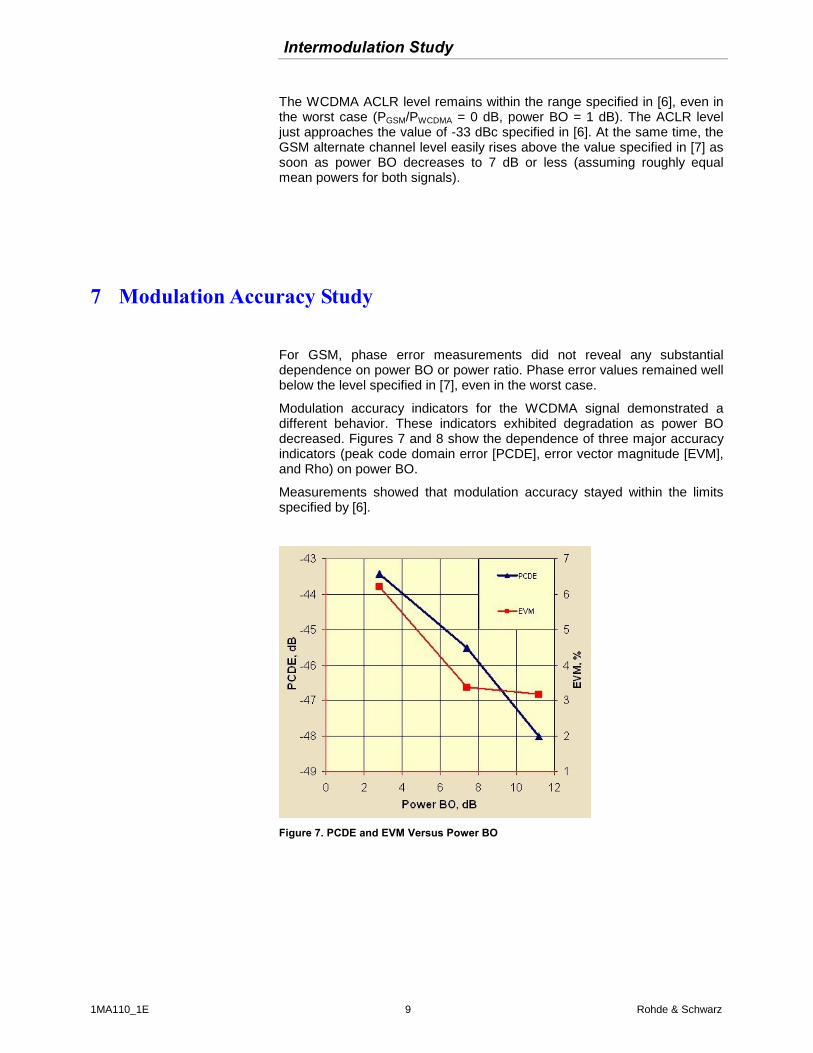
Intermodulation Study
1MA110_1E 9 Rohde amp Schwarz
The WCDMA ACLR level remains within the range specified in [6] even in the worst case (PGSMPWCDMA = 0 dB power BO = 1 dB) The ACLR level just approaches the value of -33 dBc specified in [6] At the same time the GSM alternate channel level easily rises above the value specified in [7] as soon as power BO decreases to 7 dB or less (assuming roughly equal mean powers for both signals)
7 Modulation Accuracy Study
For GSM phase error measurements did not reveal any substantial dependence on power BO or power ratio Phase error values remained well below the level specified in [7] even in the worst case
Modulation accuracy indicators for the WCDMA signal demonstrated a different behavior These indicators exhibited degradation as power BO decreased Figures 7 and 8 show the dependence of three major accuracy indicators (peak code domain error [PCDE] error vector magnitude [EVM] and Rho) on power BO
Measurements showed that modulation accuracy stayed within the limits specified by [6]
Figure 7 PCDE and EVM Versus Power BO
Modulation Accuracy Study
1MA110_1E 10 Rohde amp Schwarz
Figure 8 Rho Versus Power BO
8 Network Design Implications
The use of nonlinear devices in the downlink path leads to elevated levels of spurious emissions as well as to an increase in neighboring channel levels Such emissions can cause unwanted interference with the signals of other systems either through overlapping coverage or by being amplified in the same downlink path (except for a sole radiator in an isolated area such as a single DAS radio head within the building) Therefore steps need to be taken at the network planning stage to eliminate interference
When performing link budget and expected coverage radius calculations the network planner should properly identify the allowable composite output power of the PA An amplifier should not be driven to the maximum power specified for a CW signal This is why attention must be paid to the type of maximum output power stated in the manufacturers specifications2 It is important to distinguish between statements of (a) maximum CW power and (b) maximum mean WCDMA power
In case (a) the maximum composite power of all signals in the mix (taking into account future RF channel addition) must be at least 7 dB less than that specified by the manufacturer For case (b) the stated power value should be used as a maximum composite of all signals (even if some signals in the mix are GSM) Such an approach although somewhat conservative allows interference to be eliminated reduces the noise floor level and only negligibly degrades the modulation accuracy indicators in the downlink
2 Brief Internet research on six major amplifierDAS manufacturers by the authors showed that a wide variety of power values exists maximum power for sine wave maximum power for one or more WCDMA signals maximum power for GSM signals and even all of these values for one product None of the manufacturers provided data for signal mix however
Network Design Implications
1MA110_1E 11 Rohde amp Schwarz
A simplified link budget calculation for a known CW power output is given in Table 1 In this hypothetical example a DAS with a maximum CW output power of 30 dBm (0 dBW) was intended to radiate two signals with equal mean power Note that the maximum output power per radio channel was determined by taking power BO into account
RX BAND FREQUENCIES (MHZ)
BSDAS
1850
1865
SU
1830
1845
FORWARD LINK REVERSE LINK
BSDAS Antenna Gain (dBd) 105 SU Antenna Gain (dBd) 0
Max Amplifier Output CW Power (dBW) 0 Amplifier Output Max (W) 02
Power BO (dB) 7
Number of RF ChannelsAntenna 2
Max Amplifier OutputChannel (dBW) -10
BSDAS to Antenna Cable Run (m) 6 SU to Antenna Cable Run (m) 0
SU Diversity Gain (dB) 00 BSDAS Diversity Gain (dB) 00
BSDAS Receive Sensitivity (dBm) -105 SU Receive Sensitivity (dBm) -105
LINK BUDGET CALCULATION AREA
Central Frequency for Calibration (MHz) 1890 1890
BSDAS RF Cable Loss (dB) 064 SU RF Cable Loss (dB) 0
FW Max Allowable Path Loss (dB) 1349 RV Max Allowable Path Loss (dB) 1385
Suggested Amplifier OutputChannel (dBW) -10
Suggested Amplifier OutputChannel (W) 01
Balanced Model ERP (dBm) 299 System ERP (dBm) 299
Balanced Model ERP (W) 1 System ERP (W) 1
Balanced Link (dBm) 1349
Table 1 Link Budget Calculation - 30 dBm maximum CW Output Power
Conclusions
1MA110_1E 12 Rohde amp Schwarz
9 Conclusions
Signal interaction and signal parameter degradation were experimentally studied for the GSMWCDMA signal mix that was processed and amplified by the DAS sample The study showed that when power BO decreased below 7 dB most of the signal quality metrics degraded
Nonetheless the metrics were still within the limits defined by the respective recommendations in [6] and [7] One exception however was the AltCPR for GSM signals If GSM and WCDMA mean powers were roughly equal and BO fell below 7 dB the alternate channel level exceeded the value specified in [7]
Another phenomenon to be considered is power leakage into neighboring sub-bands caused by cross- and intermodulation For signal co-amplification in various sub-bands by a DAS (the most likely use of a DAS) such leakage might cause serious interference problems To avoid the degradation of both existing and new systems these signal quality and interference issues must be taken into account when designing and deploying multitechnology systems
These manifestations of nonlinearity have direct implications for link budget calculations in the network planning process if a multichannel PA is intended to amplify a GSMWCDMA signal mix In determining downlink output power the PA must not be driven to the maximum power specified for a CW signal Instead the composite mean power of all signals to be amplified must be at least 7 dB less than the maximum specified power Under this condition the system will not cause harmful interference in either occupied or neighboring sub-bands
As a follow-on to the study of possible nonlinear communication signal distortions future research steps might focus on a theoretical and experimental examination of the downlink performance in cellular or PCS networks The presence of nonlinear products in the BS or DAS emissions reduces the signal-to-(interference + noise) ratio and could degrade vital system parameters such as coverage interference level probability of successful call setup and dropped calls The study should evaluate the possible dependence between system performance and equipment nonlinearity
A similar study of uplink performance would also be valuable
Abbreviations and Terms
1MA110_1E 13 Rohde amp Schwarz
10 Abbreviations and Terms
3G 3rd generation (of mobile communication systems)
3GPP 3rd Generation Partnership Project
ACLR Adjacent Channel Leaking Ratio (defined for WCDMA)
AltCPR Alternate Channel Power Ratio (for GSM)
BO Power Back-Off
CDMA Code Division Multiple Access system
CW Continuous Wave (sine wave signal)
DAS Distributed Antenna System
dB Decibel (logarithmic ratio of the two values)
dBc Power level of interfering signal in relation to carrier power
dBd Unit of antenna gain measurement in relation to the gain of dipole antenna
dBm Unit of power measurement in relation to 1 mW
dBW Unit of power measurement in relation to 1 W
EDGE Enhanced Data Global Evolution for GSM
EVM Error Vector Magnitude
ERP Effective Radiated Power
FDD Frequency Division Duplex
FW Forward path (from base station to phone) in cellular network same as downlink
GPRS General Radio Packet Service
GSM Global System for Mobile communications
IIP3 Input Intermodulation Point of 3rd order
IM Intermodulation
IS-95 Interim Standard no 95 describing CDMA communication system
MHz Megahertz (frequency measurement unit)
PA Power Amplifier
PCDE Peak Code Domain Error
PCS Personal Communication System
RAN Radio Access Network
RBW Resolution Band Width (in spectrum analysis)
RF Radio Frequency
RV Reverse path (from phone to base station) in cellular networks same as uplink
Abbreviations and Terms
1MA110_1E 14 Rohde amp Schwarz
SU Subscriber Unit
UMTS Universal Mobile Telecommunication System
VBW Video Band Width (in spectrum analysis)
WCDMA Wideband Code Division Multiple Access system
11 References [1] K M Gharaibeh and M B Steer Characterization of cross modulation in multi-channel amplifiers using a statistically based behavioral modeling technique IEEE Trans on Microwave Theory and Techniques vol 51 No 12 2003 pp 2434-2444
[2] A Springer T Frauscher B Adler D Pimingsdorfer R Weigel Effects of nonlinear amplifier distortions on UMTS transmitter system performance Proc of the 2000 European Conf on Wireless Technology (ECWT) Oct 2000 Paris France pp159- 162 ISBN 0-86213-217-7
[3] K M Gharaibeh and M B Steer Modeling distortion in multi-channel communication systems IEEE Trans on Microwave Theory and Techniques vol 53 No 5 May 2005 pp 1682-1692
[4] K M Gharaibeh K G Gard and M B Steer Accurate estimation of digital communication system metrics - SNR EVM and in a nonlinear amplifier environment 64th Auto RF Tech Group Conf Orlando Florida Dec 2004
[5] H Holma and F Velez Performance of WCDMA1900 in the presence of uncoordinated narrow-band GSM interference Vehicular Technology Conference 2002 Proceedings VTC 2002-Fall 2002 IEEE 56th
[6] 3GPP TS 25143 V620 (2004-09) 3rd Generation Partnership Project Technical Specification Group Radio Access Network UTRA repeater conformance testing (Release 6) 3GPP Publication
[7] 3GPP TS 1121 V890 (2003-06) 3rd Generation Partnership Project Technical Specification Group GSMEDGE Radio Access Network Base Station System (BSS) equipment specification Radio aspects (Release 1999) 3GPP Publication
Biographies
1MA110_1E 15 Rohde amp Schwarz
12 Biographies
Igor Chugunov is currently a senior engineer in the Bechtel Telecommunications Training Demonstration and Research (TDR) Laboratory in Frederick Maryland He is experienced in wireless network design and optimization as well as in software and hardware testing His engineering background gives him both theoretical and practical knowledge of wireless access technologies
Before joining Bechtel Igor was a senior RF engineer with Cingular Wireless and Hughes Network Systems where he designed radio access networks for data and voice communication
Igor has an MSEECS degree from Kazan Tupolev State Technical University Russia
Aleksey Kurochkin executive director of Site Development and Engineering for Bechtel Telecommunications manages the Network Planning and Site Acquisition departments He is responsible for process and team integration and oversees the functional operations of more than 300 telecommunications engineers specialists and managers Aleksey is also a member of Bechtels Chief Engineering Committee Global Technology Team and BTTJ Editorial Council
Formerly Aleksey was senior director Network Planning in Bechtels Telecommunications Technology group which he originated He also introduced the Six Sigma continuous improvement program to this group Aleksey is experienced in international telecommunications business management and network implementation and his engineering and marketing background gives him both theoretical and hands-on knowledge of most wireless technologies
Before joining Bechtel Aleksey established an efficient multiproduct team at Hughes Network Systems focused on RF planning and system engineering In addition to his North American experience he has also worked in Russia and the CIS
Aleksey has an MSEECS degree in Automatic Telecommunications from Moscow Technical University of Communications and Informatics Russia
Biographies
1MA110_1E 16 Rohde amp Schwarz
Alex Smirnov is currently a test engineer in the Bechtel Telecommunications Training Demonstration and Research (TDR) Laboratory in Frederick Maryland He conducts tests and prepares test reports for telecommunications equipment He has also performed DAS testing to demonstrate product compliance with functional specifications for Cingular Wireless Earlier as a network planning engineer he planned and designed an FTTP project for Maryland and Delaware
Before joining Bechtel in 2004 Alex was an electronic engineer at Technology Device International Inc and Re-Certify Inc He has over 10 years of information technology experience in all areas of life-cycle program development including analysis design maintenance support and testing of various systems and platforms
Alex holds a masters degree in Science and Optical Engineering from Moscow State University Russia In addition he has a bachelors degree in Financial Management from the Russian Academy of Management Moscow
13 Additional Information This Application Note is a reprint of
Igor A Chugunov Aleksey A Kurochkin Alex M Smirnov
EXPERIMENTAL STUDY OF 3G SIGNAL INTERACTION IN NONLINEAR DOWNLINK RAN TRANSMITTERS
Bechtel Telecommunications Technical Journal June 2006 bull Volume 4 Number 2
With friendly permission of Bechtel Corporation
httpwwwbechteltelecomscom
Please send any comments or suggestions about this article to
TM-Applicationsrsdrohde-schwarzcom
Ordering Information
1MA110_1E 17 Rohde amp Schwarz
14 Ordering Information
Name Description Ordering number
Vector Signal Generator RampS
reg SMU200A 1141200502
RampSreg
SMU-B102 RF Path A 100 kHz to 22 GHz 1141850302
RampSreg
SMU-B103 RF Path A 100 kHz to 3 GHz 1141860302
RampSreg
SMU-B104 RF Path A 100 kHz to 4 GHz 1141870302
RampSreg
SMU-B106 RF Path A 100 kHz to 6 GHz 1141880302 RampS
reg SMU-B202 RF Path B 100 kHz to 22 GHz 1141940002
RampSreg
SMU-B103 RF Path B 100 kHz to 3 GHz 1141950002 RampS
reg SMU-B10 Baseband with ARB (64 Msamples) 1141700702
RampSreg
SMU-B13 Baseband Main Module 1141800302 RampS
reg SMU-K42 Digital Standard 3GPP FDD 1160790902
RampSreg
SMU-K43 3GPP Enhanced Tests 1160966002 Signal Analyzer and Options RampS
reg FSQ3 20 Hz to 36 GHz 1155500103
RampSreg
FSQ8 20 Hz to 8 GHz 1155500108
RampSreg
FSQ26 20 Hz to 265 GHz 1155500126
RampSreg
FS-K72 Application Firmware 3GPP-FDD BTS Transmitter Test
1154700002
For additional information about signal generators and spectrum analysers see the Rohde amp Schwarz website wwwrohde-schwarzcom
ROHDE amp SCHWARZ GmbH amp Co KG Muumlhldorfstraszlige 15 D-81671 Muumlnchen Postfach 80 14 69 D-81614 Muumlnchen
Tel (089) 4129 -0 Fax (089) 4129 - 13777 Internet httpwwwrohde-schwarzcom
This application note and the supplied programs may only be used subject to the conditions of use set forth in the download area of the Rohde amp Schwarz website
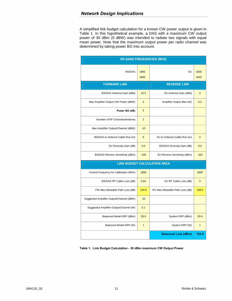
Abbreviations and Terms
1MA110_1E 14 Rohde amp Schwarz
SU Subscriber Unit
UMTS Universal Mobile Telecommunication System
VBW Video Band Width (in spectrum analysis)
WCDMA Wideband Code Division Multiple Access system
11 References [1] K M Gharaibeh and M B Steer Characterization of cross modulation in multi-channel amplifiers using a statistically based behavioral modeling technique IEEE Trans on Microwave Theory and Techniques vol 51 No 12 2003 pp 2434-2444
[2] A Springer T Frauscher B Adler D Pimingsdorfer R Weigel Effects of nonlinear amplifier distortions on UMTS transmitter system performance Proc of the 2000 European Conf on Wireless Technology (ECWT) Oct 2000 Paris France pp159- 162 ISBN 0-86213-217-7
[3] K M Gharaibeh and M B Steer Modeling distortion in multi-channel communication systems IEEE Trans on Microwave Theory and Techniques vol 53 No 5 May 2005 pp 1682-1692
[4] K M Gharaibeh K G Gard and M B Steer Accurate estimation of digital communication system metrics - SNR EVM and in a nonlinear amplifier environment 64th Auto RF Tech Group Conf Orlando Florida Dec 2004
[5] H Holma and F Velez Performance of WCDMA1900 in the presence of uncoordinated narrow-band GSM interference Vehicular Technology Conference 2002 Proceedings VTC 2002-Fall 2002 IEEE 56th
[6] 3GPP TS 25143 V620 (2004-09) 3rd Generation Partnership Project Technical Specification Group Radio Access Network UTRA repeater conformance testing (Release 6) 3GPP Publication
[7] 3GPP TS 1121 V890 (2003-06) 3rd Generation Partnership Project Technical Specification Group GSMEDGE Radio Access Network Base Station System (BSS) equipment specification Radio aspects (Release 1999) 3GPP Publication
Biographies
1MA110_1E 15 Rohde amp Schwarz
12 Biographies
Igor Chugunov is currently a senior engineer in the Bechtel Telecommunications Training Demonstration and Research (TDR) Laboratory in Frederick Maryland He is experienced in wireless network design and optimization as well as in software and hardware testing His engineering background gives him both theoretical and practical knowledge of wireless access technologies
Before joining Bechtel Igor was a senior RF engineer with Cingular Wireless and Hughes Network Systems where he designed radio access networks for data and voice communication
Igor has an MSEECS degree from Kazan Tupolev State Technical University Russia
Aleksey Kurochkin executive director of Site Development and Engineering for Bechtel Telecommunications manages the Network Planning and Site Acquisition departments He is responsible for process and team integration and oversees the functional operations of more than 300 telecommunications engineers specialists and managers Aleksey is also a member of Bechtels Chief Engineering Committee Global Technology Team and BTTJ Editorial Council
Formerly Aleksey was senior director Network Planning in Bechtels Telecommunications Technology group which he originated He also introduced the Six Sigma continuous improvement program to this group Aleksey is experienced in international telecommunications business management and network implementation and his engineering and marketing background gives him both theoretical and hands-on knowledge of most wireless technologies
Before joining Bechtel Aleksey established an efficient multiproduct team at Hughes Network Systems focused on RF planning and system engineering In addition to his North American experience he has also worked in Russia and the CIS
Aleksey has an MSEECS degree in Automatic Telecommunications from Moscow Technical University of Communications and Informatics Russia
Biographies
1MA110_1E 16 Rohde amp Schwarz
Alex Smirnov is currently a test engineer in the Bechtel Telecommunications Training Demonstration and Research (TDR) Laboratory in Frederick Maryland He conducts tests and prepares test reports for telecommunications equipment He has also performed DAS testing to demonstrate product compliance with functional specifications for Cingular Wireless Earlier as a network planning engineer he planned and designed an FTTP project for Maryland and Delaware
Before joining Bechtel in 2004 Alex was an electronic engineer at Technology Device International Inc and Re-Certify Inc He has over 10 years of information technology experience in all areas of life-cycle program development including analysis design maintenance support and testing of various systems and platforms
Alex holds a masters degree in Science and Optical Engineering from Moscow State University Russia In addition he has a bachelors degree in Financial Management from the Russian Academy of Management Moscow
13 Additional Information This Application Note is a reprint of
Igor A Chugunov Aleksey A Kurochkin Alex M Smirnov
EXPERIMENTAL STUDY OF 3G SIGNAL INTERACTION IN NONLINEAR DOWNLINK RAN TRANSMITTERS
Bechtel Telecommunications Technical Journal June 2006 bull Volume 4 Number 2
With friendly permission of Bechtel Corporation
httpwwwbechteltelecomscom
Please send any comments or suggestions about this article to
TM-Applicationsrsdrohde-schwarzcom
Ordering Information
1MA110_1E 17 Rohde amp Schwarz
14 Ordering Information
Name Description Ordering number
Vector Signal Generator RampS
reg SMU200A 1141200502
RampSreg
SMU-B102 RF Path A 100 kHz to 22 GHz 1141850302
RampSreg
SMU-B103 RF Path A 100 kHz to 3 GHz 1141860302
RampSreg
SMU-B104 RF Path A 100 kHz to 4 GHz 1141870302
RampSreg
SMU-B106 RF Path A 100 kHz to 6 GHz 1141880302 RampS
reg SMU-B202 RF Path B 100 kHz to 22 GHz 1141940002
RampSreg
SMU-B103 RF Path B 100 kHz to 3 GHz 1141950002 RampS
reg SMU-B10 Baseband with ARB (64 Msamples) 1141700702
RampSreg
SMU-B13 Baseband Main Module 1141800302 RampS
reg SMU-K42 Digital Standard 3GPP FDD 1160790902
RampSreg
SMU-K43 3GPP Enhanced Tests 1160966002 Signal Analyzer and Options RampS
reg FSQ3 20 Hz to 36 GHz 1155500103
RampSreg
FSQ8 20 Hz to 8 GHz 1155500108
RampSreg
FSQ26 20 Hz to 265 GHz 1155500126
RampSreg
FS-K72 Application Firmware 3GPP-FDD BTS Transmitter Test
1154700002
For additional information about signal generators and spectrum analysers see the Rohde amp Schwarz website wwwrohde-schwarzcom
ROHDE amp SCHWARZ GmbH amp Co KG Muumlhldorfstraszlige 15 D-81671 Muumlnchen Postfach 80 14 69 D-81614 Muumlnchen
Tel (089) 4129 -0 Fax (089) 4129 - 13777 Internet httpwwwrohde-schwarzcom
This application note and the supplied programs may only be used subject to the conditions of use set forth in the download area of the Rohde amp Schwarz website

Biographies
1MA110_1E 16 Rohde amp Schwarz
Alex Smirnov is currently a test engineer in the Bechtel Telecommunications Training Demonstration and Research (TDR) Laboratory in Frederick Maryland He conducts tests and prepares test reports for telecommunications equipment He has also performed DAS testing to demonstrate product compliance with functional specifications for Cingular Wireless Earlier as a network planning engineer he planned and designed an FTTP project for Maryland and Delaware
Before joining Bechtel in 2004 Alex was an electronic engineer at Technology Device International Inc and Re-Certify Inc He has over 10 years of information technology experience in all areas of life-cycle program development including analysis design maintenance support and testing of various systems and platforms
Alex holds a masters degree in Science and Optical Engineering from Moscow State University Russia In addition he has a bachelors degree in Financial Management from the Russian Academy of Management Moscow
13 Additional Information This Application Note is a reprint of
Igor A Chugunov Aleksey A Kurochkin Alex M Smirnov
EXPERIMENTAL STUDY OF 3G SIGNAL INTERACTION IN NONLINEAR DOWNLINK RAN TRANSMITTERS
Bechtel Telecommunications Technical Journal June 2006 bull Volume 4 Number 2
With friendly permission of Bechtel Corporation
httpwwwbechteltelecomscom
Please send any comments or suggestions about this article to
TM-Applicationsrsdrohde-schwarzcom
Ordering Information
1MA110_1E 17 Rohde amp Schwarz
14 Ordering Information
Name Description Ordering number
Vector Signal Generator RampS
reg SMU200A 1141200502
RampSreg
SMU-B102 RF Path A 100 kHz to 22 GHz 1141850302
RampSreg
SMU-B103 RF Path A 100 kHz to 3 GHz 1141860302
RampSreg
SMU-B104 RF Path A 100 kHz to 4 GHz 1141870302
RampSreg
SMU-B106 RF Path A 100 kHz to 6 GHz 1141880302 RampS
reg SMU-B202 RF Path B 100 kHz to 22 GHz 1141940002
RampSreg
SMU-B103 RF Path B 100 kHz to 3 GHz 1141950002 RampS
reg SMU-B10 Baseband with ARB (64 Msamples) 1141700702
RampSreg
SMU-B13 Baseband Main Module 1141800302 RampS
reg SMU-K42 Digital Standard 3GPP FDD 1160790902
RampSreg
SMU-K43 3GPP Enhanced Tests 1160966002 Signal Analyzer and Options RampS
reg FSQ3 20 Hz to 36 GHz 1155500103
RampSreg
FSQ8 20 Hz to 8 GHz 1155500108
RampSreg
FSQ26 20 Hz to 265 GHz 1155500126
RampSreg
FS-K72 Application Firmware 3GPP-FDD BTS Transmitter Test
1154700002
For additional information about signal generators and spectrum analysers see the Rohde amp Schwarz website wwwrohde-schwarzcom
ROHDE amp SCHWARZ GmbH amp Co KG Muumlhldorfstraszlige 15 D-81671 Muumlnchen Postfach 80 14 69 D-81614 Muumlnchen
Tel (089) 4129 -0 Fax (089) 4129 - 13777 Internet httpwwwrohde-schwarzcom
This application note and the supplied programs may only be used subject to the conditions of use set forth in the download area of the Rohde amp Schwarz website
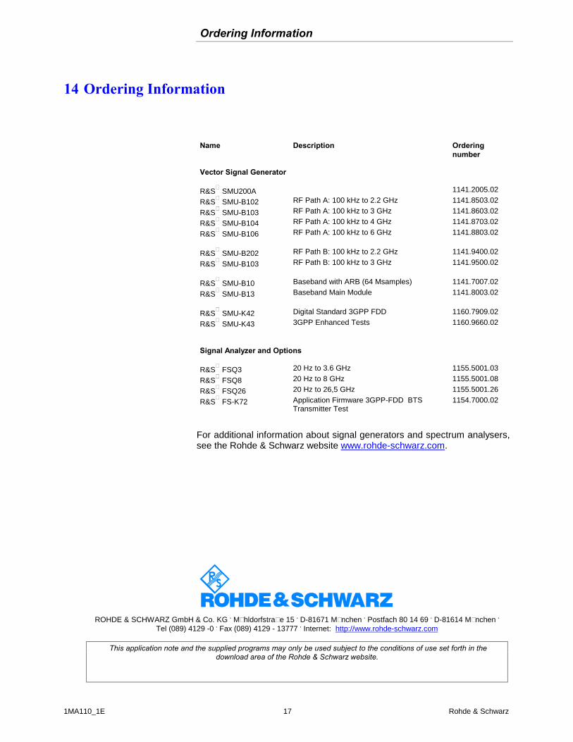