Embed Size (px)
Citation preview

Turkish J Eng Env Sci
(2014) 38: 126 – 138
c⃝ TUBITAK
doi:10.3906/muh-1401-15
Turkish Journal of Engineering & Environmental Sciences
http :// journa l s . tub i tak .gov . t r/eng ineer ing/
Research Article
Experimental investigation of screens as energy dissipaters in submerged
hydraulic jump
Sina SADEGHFAM1,∗, Ali Akbar AKHTARI1, Rasoul DANESHFARAZ2,Gokmen TAYFUR3
1Department of Civil Engineering, Faculty of Engineering, Razi University, Kermanshah, Iran2Department of Civil Engineering, Faculty of Engineering, Maragheh University, Maragheh, Iran
3Department of Civil Engineering, Faculty of Engineering, Izmir Institute of Technology, Urla, Izmir, Turkey
Received: 23.01.2014 • Accepted/Published Online: 03.09.2014 • Printed: 30.06.2015
Abstract: This study investigated the effectiveness of screens as energy dissipaters in small hydraulic structures using
physical experiments. In the experimental design, the Froude number, screen arrangements, and screen porosity were the
major controlling parameters. The experiments covered a range of Froude numbers between 2.5 and 8.5, screen porosity
of 40% and 50%, and gaps of double screens between 1 and 5 cm. The main goal of this study was investigation of the
screens creating submerged hydraulic jumps. The flow depth was digitally measured in order to perceive the turbulences
and validate the results of energy dissipation against those of the methods in the literature. The experimental results show
the importance of each parameter on the screen performance. The screens with double arrangement with the imposed
hydraulic jump dissipated more energy. The gaps of the double arrangement had an insignificant effect on energy
dissipation. The double screen with porosity of 40% had the best performance. Since the Froude number was found
to be the most effective parameter, quadratic equations as a function of this number were fitted to the experimental
results with high R2 and very low RMSE values. The quadratic equations can be employed as interpolators and/or
extrapolators.
Key words: Energy dissipation, screens, Froude number, submerged hydraulic jump, imposed hydraulic jump
1. Introduction
Control of velocity and consequently energy of water is one of the fundamental problems in hydraulic engineering.
Continuous energy transformation takes place with the flow of water in an environment. The understanding of
this energy transformation process is crucial to hydraulic engineers.
There have been theoretical and experimental studies to understand the energy transformation process
and consequently the applications of energy dissipaters [1–4]. As is well known, one of the energy dissipaters is
the creation of hydraulic jump. The hydraulic structural design causing a jump is not only an energy dissipater
but also acts as a control structure.
In addition to hydraulic jump-type energy dissipaters, there are impact-type ones as well. The impact-
type dissipaters include drops [2,3], baffled outlets (also known as the impact basin - USBR type VI), vertical
stilling wells, and sky jumps [4]. Peterka [5] investigated the design of a flip bucket as an impact-type
energy dissipater. Mason [6] outlined guidelines for impact-type energy dissipaters. Espinoza and Zevallos
∗Correspondence: [email protected]
126

SADEGHFAM et al./Turkish J Eng Env Sci
[7] investigated impact-type dissipaters from a scouring point of view while Schmocker et al. [8] investigated
them from an aeration perspective.
This study investigates screens as an energy dissipater at the downstream side of small hydraulic struc-
tures. The screen and its usage as an energy dissipater in the downstream of hydraulic structures were first
introduced by Rajaratnam and Hurtig [9], who employed 3 types of screen arrangements: single, double, and
triangular. They then investigated the effects of screen arrangement on free, imposed, and, in some cases,
submerged hydraulic jumps.
Their experimental results covered a range of Froude number between 4 and 13 and showed that screens
or porous baffles with porosity of 40% were able to dissipate more energy compared to that of free hydraulic
jumps [9]. Cakır [10] and Bozkus et al. [11,12], in their experimental study on energy dissipation, introduced
several factors like porosity, thickness, and location of screens, along with Froude numbers from 5 to 18. Cakır
[10] and Bozkus et al. [11,12] suggested 40% as the average optimum screen porosity.
According to the studies in the literature [9–12], the screen performance (the ratio of the dimensionless
parameter of energy dissipation) decreases with increase in relative location of the screens. A double screen
arrangement would have more energy loss compared to a single arrangement [10–12]. Balkıs [13] and Bozkus
et al. [14,15] investigated the effect of inclination of the screen on energy dissipation. The arrangement of
screens in their experiments resembled those in [10–12] and they varied the Froude number from 5 to 24. The
experiments of Balkıs [13] and Bozkus et al. [14,15] showed that the inclination parameter has an insignificant
effect on the energy dissipation through a screen.
Aslankara [16] and Bozkus and Aslankara [17] investigated the effects of tailwater, with Froude numbers
ranging from 5 to 22.5, on energy dissipation. Their results showed that tailwater has no significant additional
contribution on energy dissipation. However, multiple screen arrangement has more energy dissipation compared
to a single screen arrangement [16,17].
Most of the existing studies in the literature generally concentrated on imposed hydraulic jumps with
high Froude numbers. However, the submerged hydraulic jump, which is typical in small hydraulic structures,
has not earned equal attention. This is because oscillations take place in submerged hydraulic jumps. Screens
creating submerged hydraulic jump with low Froude number as energy dissipaters have not been thoroughly
studied. This study intends to fill this gap.
This paper, in addition to investigating free and imposed hydraulic jumps, mainly focuses on energy
dissipation by screens in a submerged hydraulic jump with relatively low Froude numbers ranging from 2.5 to
8.5.
2. Screens as energy dissipaters
Depending upon the flow conditions and screen type and placements, it was possible to observe different
behaviors.
2.1. Various types of behavior through collision of the supercritical flow with screens
When a screen was located in the direction of supercritical flow, 3 types of behavior were observed. 1) When
the screen was located in the subcritical region and the distance between screen and the gate was more than
the length of a full hydraulic jump, the hydraulic jump occurred before the screen (Figure 1a), agreeing with
Cakır [10]. 2) When the screen was placed in the supercritical region, the collision of the supercritical flow with
the screen imposed hydraulic jump. However, in this case, the distance between the jump point and screen
127
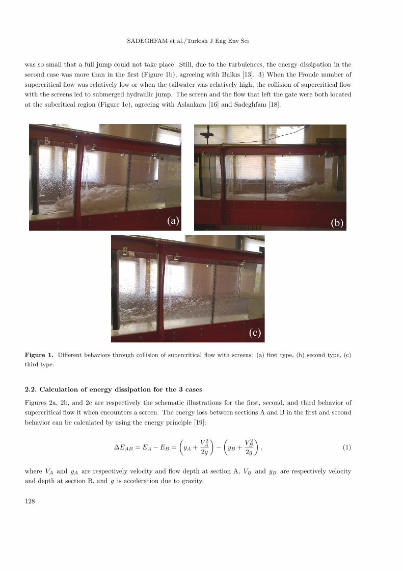
SADEGHFAM et al./Turkish J Eng Env Sci
was so small that a full jump could not take place. Still, due to the turbulences, the energy dissipation in the
second case was more than in the first (Figure 1b), agreeing with Balkıs [13]. 3) When the Froude number of
supercritical flow was relatively low or when the tailwater was relatively high, the collision of supercritical flow
with the screens led to submerged hydraulic jump. The screen and the flow that left the gate were both located
at the subcritical region (Figure 1c), agreeing with Aslankara [16] and Sadeghfam [18].
Figure 1. Different behaviors through collision of supercritical flow with screens: (a) first type, (b) second type, (c)
third type.
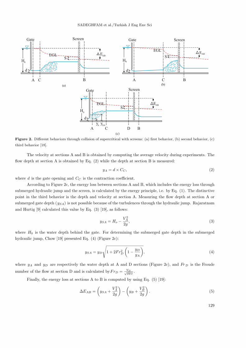
2.2. Calculation of energy dissipation for the 3 cases
Figures 2a, 2b, and 2c are respectively the schematic illustrations for the first, second, and third behavior of
supercritical flow it when encounters a screen. The energy loss between sections A and B in the first and second
behavior can be calculated by using the energy principle [19]:
∆EAB = EA − EB =
(yA +
V 2A
2g
)−
(yB +
V 2B
2g
), (1)
where VA and yA are respectively velocity and flow depth at section A, VB and yB are respectively velocity
and depth at section B, and g is acceleration due to gravity.
128
SADEGHFAM et al./Turkish J Eng Env Sci
A C B
SEAB
Gate Screen
EGL
d
(a)
H0
A C B
EABS
Gate Screen
d
EGL
(b)
H0
SAy
Gate
A CAy
d
EGLS
Screen
D B
EAB
)a(c
H0
Figure 2. Different behaviors through collision of supercritical with screens: (a) first behavior, (b) second behavior, (c)
third behavior [18].
The velocity at sections A and B is obtained by computing the average velocity during experiments. The
flow depth at section A is obtained by Eq. (2) while the depth at section B is measured:
yA = d× CC , (2)
where d is the gate opening and CC is the contraction coefficient.
According to Figure 2c, the energy loss between sections A and B, which includes the energy loss through
submerged hydraulic jump and the screen, is calculated by the energy principle, i.e. by Eq. (1). The distinctive
point in the third behavior is the depth and velocity at section A. Measuring the flow depth at section A or
submerged gate depth (ySA) is not possible because of the turbulences through the hydraulic jump. Rajaratnam
and Hurtig [9] calculated this value by Eq. (3) [19], as follows:
ySA = Ho −V 2A
2g, (3)
where H0 is the water depth behind the gate. For determining the submerged gate depth in the submerged
hydraulic jump, Chow [19] presented Eq. (4) (Figure 2c):
ySA = yD
√1 + 2Fr2D
(1− yD
yA
), (4)
where yA and yD are respectively the water depth at A and D sections (Figure 2c), and Fr D is the Froude
number of the flow at section D and is calculated byFrD = VD√gyD
.
Finally, the energy loss at sections A to B is computed by using Eq. (5) [19]:
∆EAB =
(ySA +
V 2A
2g
)−
(yB +
V 2B
2g
). (5)
129

SADEGHFAM et al./Turkish J Eng Env Sci
The contraction coefficient (Cc) in Eq. (2) for the free and submerged flows is calculated by the analytical
results of Belaud et al. [20], through the ratio of gate opening to the depth of the approaching flow behind the
gate (Figure 3).
0.20 0.4 0.6 0.80 55.
0 60.
0 65.
0 70.
0 75.
0 80.
d/H0
Cc
Free FlowSubmerged Flow
1
Figure 3. The contraction coefficient presented for submerged and free flows by Belaud et al. [20].
Admittedly, using the results of the work of Belaud, the value of CC in this study varies in the interval
of 0.614 to 0.628. It is worth noting that a constant value of 0.625 for the contraction coefficient (CC) were
considered in [10–17].
3. Dimensional analysis
Flow between the gate and the screen was theoretically analyzed and the following parameters were identified
to perform the dimensional analysis [10,13,16,18]:
S = f1 (Q, d,w, yA, yB , yC , x,X, p,G, t, g, ρ, µ) , (6)
where S is energy dissipation due to the screen, whose dimension is [L ]. Other parameters of above equa-
tions (Q, d,w, yA, yB , yC , x,X, p, k, t, g, ρ, andµ) and their dimension are, respectively, discharge [L3T−1 ], gate
opening [L ], width of channel [L ], water depth at section A [L ], water depth at section B [L ], water depth
at section C [L ], distance from upstream end of the imposed hydraulic jump to the screen [L ], distance be-
tween the screen and the gate [L ], porosity of screen, gaps between screens [L ], thickness of the screen [L ],
gravitational acceleration [LT −2 ], density of water [ML−3 ], and dynamic viscosity of water [ML−1T−1 ].
Energy at section A symbolized by EA , length of free hydraulic jump (L), and Froude number at section
B (Fr B) can be described as the following functions:
EA = f2 (Q, d,w, yA, g) , (7)
L = f3 (Q,w, yA, g) , (8)
FrB = f4 (Q,w, yB, g) . (9)
Thus, substituting w , yA , and yB into Eq. (6) for EA , L , and Fr B respectively leads to:
S = f5 (Q, d,EA, L, FrB , yC , x,X, p,G, t, g, ρ, µ) . (10)
130

SADEGHFAM et al./Turkish J Eng Env Sci
By selecting yA , g , and ρ as repeating variables, the following nondimensional equation is obtained:
S
yA= f6
(EA
yA, F rA,
L
yA, F rC ,
x
yA,X
yA, p,
G
yA,t
yA,yAd,Re
), (11)
in which Re is the Reynolds number. By reorienting Eq. (10), it can be represented in the following dimensionless
format:
S
EA= f7
(FrA, p,
G
t,
∣∣∣∣FrB,EA
d,x
d,x
L,X
d,CC , Re,
t
d
∣∣∣∣) . (12)
It is worth noting that the parameters Fr B , EA
d , xd , X
d and xL , which can be considered as case studies in future
works, are out of the scope of the current study. As far as the contraction coefficient CC , which is a function
of d/H0 and constant for each case of the experiment, is concerned, its value was obtained in a research work
done by Belaud et al. [20]. Since in our investigation the type of flow is free surface flow, in which gravitational
effects are more dominant, the importance of the Reynolds number is secondary and it resultantly is neglected.
The thickness parameter of screens was introduced as an insignificant one in the literature [10,13,14], so td is
assumed to be a negligible parameter.
By taking all the mentioned justifications into account and dropping the discussed parameters of the
previous paragraph, the final dimensionless equation is obtained as represented in Eq. (13). As can be seen,
the Froude number of supercritical flow (Fr A), porosity of screen (p), and arrangement of double screen ( Gt )
play an important role in the current study.
S
EA= f7
(FrA, p,
G
t
)(13)
4. Experimental set-up and experiments
The experiments in the current study were performed in a horizontal open channel (flume) of 0.3 m wide, 0.5
m deep, and 5 m long at Maragheh University in Iran (Figure 1). Figure 4 presents the detailed schematic
representation of the experimental set-up. The inlet discharge was supplied by 2 pumps that were fed by channel
tank, and the inlet flow was controlled by 2 valves that were installed in the outlet of the pumps (Figure 4). The
inlet discharge was measured by 2 rotameters, which were installed in the outlet of the pumps. The rotameters
were calibrated by the accurate measurement of a velocity meter in subcritical flow at numerous depths and
discharges. Additionally, in this step, turbulence and uniformity of the inlet velocity profile were controlled.
The gate was installed at a distance of 1 m from the inlet, and the opening was fixed at 2.6 cm. The Froude
number of supercritical flow was varied from about 2.5 to 8.5. With the assumption that there was no energy
loss between the gate outlet and vena contracta, all the initial energy calculations were done with respect to
the depth at the vena contracta.
The experiments were performed in 2 series. The first was conducted by measuring the depth by using
a point gauge, and the second was conducted by digital measurement equipped with ultrasonic sensors and an
accuracy of 140 data per second. In the first series of experiments, the flow depths were measured by point
gauge through calculating the average number of 3 depths in the middle and 7.5 cm from the channel walls.
The equations of Rajaratnam and Subramanya [21] and Chow [19] were used to calculate the depth of the
submerged gate. In the second series of experiments, all depths and especially the depth of the submerged gate
131

SADEGHFAM et al./Turkish J Eng Env Sci
were measured by digital measurement in 45 s. The use of digital measurement was very efficient in measuring
the water surface profile.
Gate
Screen
Rotameter
Valve
Tank
Inlet Outlet
Pump
5m
1.25m1m
Figure 4. Schematic picture of experimental set-up.
The screens used in the experiments were made of polyethylene and each screen had a thickness of 1
cm. Porosities of 40% and 50% were created by holes of 1 cm in diameter through uniform square meshes.
The screens had single and double arrangements, which were created by gaps of 1, 3, and 5 cm. Like in the
experiments of Rajaratnam and Hurtig [9], the screens were fixed at a distance of 1.25 m from the gate.
5. Analysis of experimental results
In this section, quite a few experiments are devised to analyze the behavior of a supercritical flow when it
encounters screens, which cause submerged hydraulic jumps generated upstream of the screens.
In the analysis of the experimental results, 2 parameters, namely percent energy loss (%) and Fr number,
were evaluated for the screen performance. Figures 5–8 respectively compare performances for a single screen
with porosity of 40% and 50% and double screens with 1 cm gap and porosity of 40% and 50%. In these
figures, parts a and b illustrate, respectively, performance of screens with regard to upstream and downstream.
The digital measurements were compared with the results of equations of Chow [19] and Rajaratnam and
Subramanya [21]. According to Figures 5–8, it can be inferred that the equation of Rajaratnam performs
satisfactorily in simulating the submerged hydraulic jump. It is worth noting that by increasing the Froude
number the performance of screens in dissipating the energy increases for both the upstream and downstream
flow conditions. In Figures 5–8, the straight lines show the energy loss due to the classical free hydraulic jump.
As seen, the energy loss through screens for all conditions is more than the energy loss through free hydraulic
jump.
0
0.2
0.4
0.6
0.8
1
0 1 2 3 4 5 6 7 8 9 10
(E A
- E
B)
/ E
A
Fr A
by Chow's Eq. by Rajaratnam and Subramanya's Eq. Measured Free H.J.
(a)
0
1
2
3
4
5
0 1 2 3 4 5 6 7 8 9 10
(E A
- E
B) /
E B
Fr A
by Chow's Eq. by Rajaratnam and Subramanya's Eq. Measured Free H.J.
(b)
Figure 5. The energy loss of single screens with the porosity of 40%: (a) performance of screens with regard to upstream,
(b) performance of screens with regard to downstream.
132

SADEGHFAM et al./Turkish J Eng Env Sci
0
0.2
0.4
0.6
0.8
1
0 1 2 3 4 5 6 7 8 9 10
(E A
- E
B)
/ E
A
Fr A
by Chow's Eq. by Rajaratnam and Subramanya's Eq. Measured Free H.J.
(a)
0
1
2
3
4
5
0 1 2 3 4 5 6 7 8 9 10
(E A
- E
B)
/ E
B
Fr A
by Chow's Eq. by Rajaratnam and Subramanya's Eq. Measured Free H.J.
(b)
Figure 6. The energy loss of single screens with porosity of 50%: (a) performance of screens with regard to upstream,
(b) performance of screens with regard to downstream.
0
0.2
0.4
0.6
0.8
1
0 1 2 3 4 5 6 7 8 9 10
(E A
- E
B)
/ E
A
Fr A
by Chow's Eq. by Rajaratnam and Subramanya's Eq. Measured Free H.J.
(a)
0
1
2
3
4
5
0 1 2 3 4 5 6 7 8 9 10
(E A
- E
B)
/ E
B
Fr A
by Chow's Eq. by Rajaratnam and Subramanya's Eq. Measured Free H.J.
(b)
Figure 7. The energy loss of double screens with porosity of 40%: (a) performance of screens with regard to upstream,
(b) performance of screens with regard to downstream.
0
0.2
0.4
0.6
0.8
1
0 1 2 3 4 5 6 7 8 9 10
(E A
- E
B)
/ E
A
Fr A
by Chow's Eq. by Rajaratnam and Subramanya's Eq. Measured Free H.J.
(a)
0
1
2
3
4
5
0 1 2 3 4 5 6 7 8 9 10
(E A
- E
B)
/ E
B
Fr A
by Chow's Eq. by Rajaratnam and Subramanya's Eq. Measured Free H.J.
(b)
Figure 8. The energy loss of double screen with porosity of 50%: (a) performance of screens with regard to upstream,
(b) performance of screens with regard to downstream.
Figures 9–12 present effects of single screen, double screen, porosity, and different screen gaps on energy
loss as a function of Fr number. In Figures 9–11, parts a and b represent, respectively, performance of screens
with regard to upstream and downstream. SS and DS respectively stand for single screen and double screen. P
stands for porosity and G stands for gap.
Figure 9 compares the results of a single screen with porosity of 40% and 50%. Based on this figure, the
results of the screen with porosity of 40% and 50% are correlated. Rajaratnam and Hurtig [9] claimed that
133

SADEGHFAM et al./Turkish J Eng Env Sci
40% porosity is the optimum rate. However, according to Figure 9, this is not exactly the case. This is because
of the different flow conditions in 2 cases. In the Froude number range in this study, the supercritical flow in
collision with single screens with porosity of 50% shows the imposed hydraulic jump (second behavior) and the
second behavior creates more energy loss due to the extra turbulences compared to the first (free hydraulic
jump) and third (submerged hydraulic jump) behaviors.
0
0.2
0.4
0.6
0.8
1
0 1 2 3 4 5 6 7 8 9 10
(E A
- E
B)
/ E
A
Fr A
SS-P40
SS-P50
Free H.J.
(a)
0
1
2
3
4
5
0 1 2 3 4 5 6 7 8 9 10 (E
A -
E B
) /
E B
Fr A
SS-P40
SS-P50
Free H.J.
(b)
Figure 9. Comparison of the screen results of the porosity of 40% and 50%: (a) the performance of the screens with
regard to upstream, (b) performance of the screens with regard to downstream.
0
0.2
0.4
0.6
0.8
1
0 1 2 3 4 5 6 7 8 9 10
(E A
- E
B)
/ E
A
Fr A
SS-P40
DS-P40-G1
Free H.J.
(a)
0
1
2
3
4
5
0 1 2 3 4 5 6 7 8 9 10
(E A -
E B
) /
E B
Fr A
SS-P40
DS-P40-G1
Free H.J.
(b)
Figure 10. Comparison of single and double screens with porosity of 40%: (a) performance of the screens with regard
to upstream, (b) performance of the screens with regard to downstream.
0
0.2
0.4
0.6
0.8
1
0 1 2 3 4 5 6 7 8 9 10
(E A
- E
B)
/ E
A
Fr A
SS-P50
DS-P50-G1
Free H.J.
(a)
0
1
2
3
4
5
0 1 2 3 4 5 6 7 8 9 10
(E A -
E B
) /
E B
Fr A
SS-P50
DS-P50-G1
Free H.J.
(b)
Figure 11. Comparison of the single and double screens with porosity of 50%: (a) performance of the screens with
regard to upstream, (b) performance of the screens with regard to downstream.
134

SADEGHFAM et al./Turkish J Eng Env Sci
0
0.2
0.4
0.6
0.8
1
0 1 2 3 4 5 6 7 8 9 10
(E A
- E
B)
/ E
A
Fr A
DS-P40-G1 DS-P40-G3 DS-P40-G5 Free H.J.
(a)
0
0.2
0.4
0.6
0.8
1
0 1 2 3 4 5 6 7 8 9 10
(E A
- E
B)
/ E
A
Fr A
DS-P50-G1 DS-P50-G3 DS-P50-G5 Free H.J.
(b)
Figure 12. Comparison of the screens with double arrangement: (a) performance of the screens with regard to upstream
with porosity of 40%, (b) performance of the screens with regard to upstream with porosity of 50%.
Figures 10 and 11 respectively compare the results of single and double screens with porosity of 40% and
50% for both upstream and downstream flow conditions. The double arrangement of screens with 40% porosity
has more energy loss compared to single arrangements (Figure 10). The energy loss of the single arrangement
case is almost the same as that of the double arrangement for 50% porosity (Figure 11).
Figures 12a and 12b compare the results of the double screen arrangement with gaps of 1, 3, and 5 cm
with porosity of 40% and 50%, respectively. According to Figure 12, the gap between screens in the study range
(Fr number range: 2.5–8.5) has an insignificant effect on energy dissipation. Figure 13 also illustrates some
comparisons between existing studies and the current one. Based on this figure, it is observed that the results
are approximately within the same range.
0
0.2
0.4
0.6
0.8
1
0 1 2 3 4 5 6 7 8 9 10
(a) (b)
( E
A -
E B
) /
E A
Fr A
SS-P40 (Rajaratnam) DS-P40 (Rajaratnam) SS-P40 (Present Study) DS-P40 (Present Study) Free H. J.
0
0.2
0.4
0.6
0.8
1
0 1 2 3 4 5 6 7 8 9 10
( E
A -
E B
) /
E A
Fr A
SS-P40 (Çakır) SS-P50 (Çakır) DS-P50 (Çakır) SS-P40 (Balkış)SS-P40 (Present Study) DS-P40 (Present Study) DS-P50 (Present Study) DS-P40 (Aslankara) Free H. J.
Figure 13. The comparison of the current and former studies.
Based on the experimental results in this study, nonlinear regression equations (quadratic polynomial)
were developed as a function of Fr number. The general forms of these equations are presented in Eqs. (14)
and (15):
(EA − EB)/EA =P1(FrA)2 + P2(FrA) + P3, (14)
(EA − EB)/EB =P1(FrA)2 + P2(FrA) + P3, (15)
where P1 , P2 , and P3 are constants (coefficients). These equations indicate the importance of the Froude
number in energy dissipation.
Tables 1 and 2 present the obtained optimal values of the parameters of the equations for each case. The
optimal values of the coefficients in Tables 1 and 2 were obtained by regression method using MATLAB. The
135
SADEGHFAM et al./Turkish J Eng Env Sci
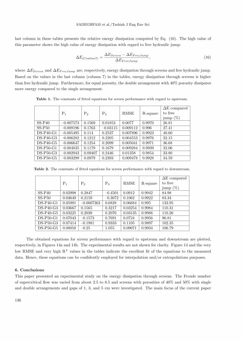
last column in these tables presents the relative energy dissipation computed by Eq. (16). The high value of
this parameter shows the high value of energy dissipation with regard to free hydraulic jump:
∆E(Coulmn7) =∆EScreen −∆EFreeJump
∆EFreeJump, (16)
where ∆EScreen and ∆EFreeJump are, respectively, energy dissipation through screens and free hydraulic jump.
Based on the values in the last column (column 7) in the tables, energy dissipation through screens is higher
than free hydraulic jump. Furthermore, for equal porosity, the double arrangement with 40% porosity dissipates
more energy compared to the single arrangement.
Table 1. The constants of fitted equations for screen performance with regard to upstream.
P1 P2 P3 RMSE R-square
∆E comparedto freejump (%)
SS-P40 –0.007573 0.1569 0.01853 0.0077 0.9970 26.81SS-P50 –0.009196 0.1763 –0.03115 0.009112 0.996 27.41DS-P40-G1 –0.005495 0.114 0.2537 0.007896 0.9923 40.60DS-P40-G3 –0.006282 0.1212 0.2205 0.004553 0.9976 32.15DS-P40-G5 –0.006647 0.1254 0.2099 0.005041 0.9971 36.68DS-P50-G1 –0.004835 0.1179 0.1679 0.009284 0.9939 32.06DS-P50-G3 –0.002943 0.09407 0.2446 0.01358 0.9854 33.80DS-P50-G5 –0.003299 0.0979 0.2393 0.009478 0.9928 34.59
Table 2. The constants of fitted equations for screen performance with regard to downstream.
P1 P2 P3 RMSE R-square
∆E comparedto freejump (%)
SS-P40 0.02998 0.2847 –0.4501 0.0912 0.9942 84.98SS-P50 0.03649 0.2159 –0.3072 0.1062 0.9922 83.34DS-P40-G1 0.05991 –0.0007363 0.6828 0.06684 0.995 133.95DS-P40-G3 0.03667 0.1565 0.3217 0.03254 0.9984 110.31DS-P40-G5 0.03225 0.2039 0.2076 0.03135 0.9986 110.26DS-P50-G1 0.07043 –0.1573 0.7691 0.0724 0.9956 96.81DS-P50-G3 0.07414 –0.1981 0.9333 0.1105 0.9897 102.35DS-P50-G5 0.08058 –0.25 1.055 0.09071 0.9934 106.79
The obtained equations for screen performance with regard to upstream and downstream are plotted,
respectively, in Figures 14a and 14b. The experimental results are not shown for clarity. Figure 14 and the very
low RMSE and very high R2 values in the tables indicate the excellent fit of the equations to the measured
data. Hence, these equations can be confidently employed for interpolation and/or extrapolations purposes.
6. Conclusions
This paper presented an experimental study on the energy dissipation through screens. The Froude number
of supercritical flow was varied from about 2.5 to 8.5 and screens with porosities of 40% and 50% with single
and double arrangements and gaps of 1, 3, and 5 cm were investigated. The main focus of the current paper
136

SADEGHFAM et al./Turkish J Eng Env Sci
was on the submerged hydraulic jump. The amount of energy loss through submerged jumps was gauged by
digital measurements and then the results were compared with 2 conventional equations (namely Chow’s and
Rajaratnam’s equations).
0
0.2
0.4
0.6
0.8
1
2 3 4 5 6 7 8 9
(E A
- E
B)
/ E
A
Fr A
Fitted Eq. (SS-P40)
Fitted Eq. (SS-P50)
Fitted Eq. (DS-P40-G1)
Fitted Eq. (DS-P50-G1)
Free H.J.
(a)
0
1
2
3
4
5
6
2 3 4 5 6 7 8 9
(E A -
E B
) /
E B
Fr A
Fitted Eq. (SS-P40)
Fitted Eq. (SS-P50)
Fitted Eq. (DS-P40-G1)
Fitted Eq. (DS-P50-G1)
Free H.J.
(b)
Figure 14. Fitted equations for different arrangement of screens: (a) performance of the screens with regard to upstream,
(b) performance of the screens with regard to downstream.
According to the experimental results, the screens have more energy loss compared to free hydraulic
jumps, and the amount of energy dissipation increases with the increasing of the Froude number. The double
screen arrangements have more energy dissipations compared to the single arrangement within the study range.
The gaps of the double arrangement have an insignificant effect on energy dissipation. Additionally, in the
second behavior (imposed hydraulic jump), there is more energy loss compared to the 2 other cases (free and
submerged hydraulic jump).
The quadratic polynomial equations were fitted to the results of screen performance with acceptable
values of R2 and RMSE. These equations, which can be used for interpolation and extrapolation purposes,
indicate that energy dissipation through screens is mainly a function of Froude number.
Based on computing energy dissipation through screens compared to free hydraulic jump, the double
screen with porosity of 40% has the best performance.
The presented method is mostly useful for weak and medium jumps, not strong jumps that happen in
dam weirs. This method generally is suggested for the regime transformation in the conveyance channels at
the drops, entrance of basins, and settling basin. Because in dam weirs the possibility of blockage of holes and
consequently overtopping occurrence is inevitable, its usage in the USBR type 1, type 2, and type 3 and flip
bucket is recommended. As an application in a stilling basin, where a screen network is installed right before the
entrance to the basin, this device (screen network) can be beneficial in 2 ways: omission of floating objects and
transforming of the flow regime. In addition, in flow conveyance channels through setting the screen network
after the drops, there will be no need for stilling the basin. The restriction in installation of screen networks in
dams is the main disadvantage of this devise.
References
[1] Wei CY, Lindell JE. Hydraulic design of stilling basin and energy dissipators. In: Mays LW, editor. Hydraulic
Design Handbook. Chicago, IL, USA: McGraw-Hill; 1999. pp. 18.1–18.55.
[2] Chanson H. Energy dissipation and drop structures in ancient times: the Roman dropshafts. In: Proceedings of
25th Hydrology & Water Resources Symposium, 2nd International Conference on Water Resources & Environment
Research, Vol. 2. Brisbane, Australia; 1999. pp. 987–992.
137

SADEGHFAM et al./Turkish J Eng Env Sci
[3] Carvalho RF, Leandro J. Hydraulic characteristics of a drop square manhole with a downstream control date. J
Irrig Dain E-ASCE 2011; 138: 569–576.
[4] Burgi PH. Hydraulic design of vertical stilling wells. J Hydr Div 1975; 101: 801–816.
[5] Peterka AJ. Hydraulic Design of Stilling Basins and Energy Dissipators. 4th ed. Washington, DC, USA: Department
of the Interior, Bureau of Reclamation; 1978.
[6] Mason PJ. Practical guidelines for the design of flip buckets and plunge pools. Int Water Power Dam Constr 1993;
45: 40–45.
[7] Espinoza EVM, Zevallos JMK. Scour in non-cohesive soil due to the impact of jet spillway out of ski jump. In:
Walton R, editor. Proceedings of World Water and Environmental Resources Congress, Anchorage, Alaska: ASCE;
2005. pp. 1–11.
[8] Schmocker L, Pfister M, Hager WH, Minor HE. Aeration characteristics of ski jump jets. J Hydraul Eng-ASCE
2008; 134: 90–97.
[9] Rajaratnam N, Hurtig KI. Screen-type energy dissipator for hydraulic structures. J Hydraul Eng-ASCE 2000; 126:
310–312.
[10] Cakır P. Experimental investigation of energy dissipation through screens. MSc, Middle East Technical University,
Ankara, Turkey, 2003.
[11] Bozkus Z, Cakir P, Ger M, Ozeren Y. Energy dissipation through screens. In: Sehlke G, Hayes DF, Stevens DK,
editors. Proceedings of the 2004 World Water and Environmental Resources Congress. Salt Lake City, Utah, USA:
ASCE; 2004. pp. 1–8.
[12] Bozkus Z, Cakir P, Ger M. Energy dissipation by vertically placed screens. Can J Civil Eng 2007; 34: 557–564.
[13] Balkıs G. Experimental investigation of energy dissipation through inclined screens. MSc, Middle East Technical
University, Ankara, Turkey, 2004.
[14] Bozkus Z, Balkis G, Ger M. Effect of inclination of screens on energy dissipation downstream of small hydraulic
structures. In: Schmidt N, editor. Proceedings of the 17th Canadian Hydrotechnical Conference, Edmonton,
Alberta, Canada; 2005. pp. 881–890.
[15] Bozkus Z, Gungor E, Ger M. Energy dissipation by triangular screens. In: Proceedings of the Seventh International
Congress on Advances in Civil Engineering, Yıldız Technical University, Istanbul, Turkey: ACE; 2006.
[16] Aslankara V. Experimental investigation of tailwater effect on the energy dissipation through screens. MSc, Middle
East Technical University, Ankara, Turkey, 2007.
[17] Bozkus Z, Aslankara V. Tailwater effect on the energy dissipation through screens. In: Proceedings of the 8th
International Congress on Advances in Civil Engineering, Eastern Mediterranean University, Famagusta, North
Cyprus: ACE; 2008.
[18] Sadeghfam S. Experimental investigation of screens as energy dissipator. MSc, Razi University, Kermanshah, Iran,
2012.
[19] Chow VT. Open Channel Hydraulics. 3rd ed. New York, NY, USA: McGraw-Hill; 1959.
[20] Belaud G, Cassan L, Baume JP. Calculation of contraction coefficient under sluice gates and application to discharge
measurement. J Hydraul Eng-ASCE 2009; 135: 1086–1091.
[21] Rajaratnam N, Subramanya K. Flow immediately below submerged sluice gate. J Hydr Div 1977; 93: 57–77.
138