Embed Size (px)
Citation preview

light-gaugeructure in ancimens areedolts ine underfill plate,
erimentalis observed.
Experimental Investigation of Light-Gauge Steel Plate ShearWalls
Jeffrey W. Berman1 and Michel Bruneau2
Abstract: This paper describes the prototype design, specimen design, experimental setup, and experimental results of threesteel plate shear wall concepts. Prototype light-gauge steel plate shear walls are designed as seismic retrofits for a hospital starea of high seismicity, and emphasis is placed on minimizing their impact on the existing framing. Three single-story test spedesigned using these prototypes as a basis, two specimens with flat infill plates(thicknesses of 0.9 mm) and a third using a corrugatinfill plate (thickness of 0.7 mm). Connection of the infill plates to the boundary frames is achieved through the use of bcombination with industrial strength epoxy or welds, allowing for mobility of the infills if desired. Testing of the systems is donquasi-static conditions. It is shown that one of the flat infill plate specimens, as well as the specimen utilizing a corrugated inachieve significant ductility and energy dissipation while minimizing the demands placed on the surrounding framing. Expresults are compared to monotonic pushover predictions from computer analysis using a simple model and good agreement
DOI: 10.1061/(ASCE)0733-9445(2005)131:2(259)
CE Database subject headings: Shear walls; Experimentation; Retrofitting; Seismic design; Cyclic design; Steel plates.
dthe
fieldg ofbe a
;993;ro-t arehavedst-
sist-ex-from
ctiveis toy seis
ein-trofitreat-
n totheulararerlight-
ignedpitalel
c-ight
teirdersdi-
t-d re-
i-ed to
nt hos-ere-signin theere
d the
ntalail:
keand
00.until
al pa-ust bewas; ap-
33-
Introduction
Past research on steel plate shear walls(SPSW) has investigatethe use of flat hot-rolled plates as infill panels. By allowinginfill plates to buckle in shear, develop diagonal tensionaction, and then dissipate energy through the cyclic yieldinthe infill in tension, researchers have shown that SPSWs canuseful seismic energy dissipation system(Thorburn et al. 1983Timler and Kulak 1983; Caccese et al. 1993; Elgaaly et al. 1Driver et al. 1997; Rezai 1999; etc.). Such research has also pduced useful analytical models for representing SPSWs thaallowed to develop tension field action, and some of thesebeen implemented in a steel design standard[Canadian StandarAssociation (CSA) 2001]. However, use of SPSWs with horolled infill plates(typically 5 mm, 3/16 in., minimum thicknes)in a retrofit situation, in which it would be used to infill an exing bay, would likely require significant reinforcement of theisting beams and columns due to the large demands inducedthe plate yielding.
Light-gauge SPSWs could provide engineers with an effeoption for the seismic retrofit of older buildings. The conceptcreate a system that is strong enough to resist the necessar
1PhD Candidate, Dept. of Civil, Structural and EnvironmeEngineering, Univ. at Buffalo, Amherst, NY 14260. [email protected]
2Deputy Director, Multidisciplinary Center for EarthquaEngineering Research, Professor, Dept. of Civil StructuralEnvironmental Engineering, Univ. at Buffalo, Buffalo, NY 14260-43
Note. Associate Editor: Christopher J. Earls. Discussion openJuly 1, 2005. Separate discussions must be submitted for individupers. To extend the closing date by one month, a written request mfiled with the ASCE Managing Editor. The manuscript for this papersubmitted for review and possible publication on March 25, 2003proved on May 11, 2004. This paper is part of theJournal of StructuralEngineering, Vol. 131, No. 2, February 1, 2005. ©ASCE, ISSN 07
9445/2005/2-259–267/$25.00.JOURNAL
-
mic forces, and yet light enough to avoid having to heavily rforce existing framing due to the increased demands the restrategy may place on it. Furthermore, an interest exists in cing systems that could be installed with minimum disruptiothe function and occupants of an existing building, and, incontext of the seismic retrofit of hospitals, that could be modto facilitate relocation of the light-gauge infills as floor plansrearranged(something that often occurs in hospitals). This papedescribes the design and quasi-static testing of three suchgauge SPSW systems.
Prototype Design
Two prototype light-gauge steel plate shear walls were desas seismic retrofit options for a prototype demonstration hos(Yang and Whittaker 2002). This hospital is a four-story steframed building with plan dimensions of 83.5 ms274 ftd in theeast–west direction and 17.2 ms56.4 ftd in the north–south diretion. The floor plan is shown in Fig. 1. The first story has a heof 4.1 m s13.5 ftd and the others are 3.8 m highs12.5 ftd. Gravityframing consists of 140 mms5.5 in.d thick reinforced concrefloor slabs on steel deck that rest on steel floor beams and gwhich carry the gravity loads to columns. In the north–southrection (the direction of interest here), there are four momenresisting three-bay frames that act as the primary lateral loasisting system(located on frame lines B, H, J, and N). Theremaining frames(termed gravity frames) in the north–south drection utilize flexible web–angle connections that are assumhave no resistance to lateral loading. Yang and Whittaker(2002)describe several sets of steel section sizes meant to represepitals constructed in different time periods and locations, thfore, satisfying different building code requirements. The derepresenting a typical hospital constructed on the west coast1960s(WC60) was used in this study. The test specimens wdesigned to retrofit the north–south frames and they include
flexible web–angle beam-to-column connections. To minimize theOF STRUCTURAL ENGINEERING © ASCE / FEBRUARY 2005 / 259

tes
di-gofitcauseple-
ency
ravityhesectivewassoil.EMAedard
ns
ear.sid-
r tributelyap-f thetiff-fsis to
r bothroce-sor theler
vel
dwith
as-ulatedand
r-
etoflat
thetted
alsossionntage.ded
PSW-
andtse-the
platee forL iswns and
s inions.inedpeci-
hick-
d
forces applied to the existing framing by the yielding infill pla(i.e., to avoid having to strengthen the existing columns), it wasdecided that every line of gravity framing in the north–southrection would be retrofitted. The middle bay(between framinlines 3 and 4) was arbitrarily chosen as the location for the retron each frame line. This choice may restrict access andserviceability issues that would have to be considered in immentation.
The equivalent lateral force procedure of Federal EmergManagement Agency(FEMA) Document, FEMA 302(FEMA1997), was used to calculate a design base shear. Tributary gloads for one bay of north–south framing were determined. Tand a portion of the design live load were used as the aseismic weight for a single-gravity frame line. The hospitalassumed to be located in Northridge, California on a class DBecause a SPSW is not a structural system covered by F302, a seismic force reduction factor,R, was derived from thSPSW design provisions of the Canadian Steel Design StanCAN/CSA-S16-01(CSA 2001). For a limited ductility SPSW(i.e., SPSW in frames with simple beam-to-column connectio),the CSA requirements would be equivalent to anR of 3.33 for usein FEMA 302, which was used for calculation of the base shAn importance factor,I, of 1.5 was used because this is conered a critical facility. The resulting seismic coefficient,Cs,was determined to be 0.58 and the corresponding base sheatary to one of the gravity frames was approxima1,420 kNs320 kipsd. Note that the calculation of base shearplied to one of the gravity frames neglected the stiffness oexisting moment frames(they were assumed to have a small sness relative to the infilled gravity frames) as well as the effect otorsional response in plan, but still provides a reasonable badevelop plate sizes for the purpose of this study.
For the calculated design base shear, plate thicknesses foflat and corrugated plate specimens were found using the pdure described in Berman and Bruneau(2003b). This procedure ibased on development of the plastic collapse mechanisms fstrip model illustrated in Fig. 2, that was formulated by Timand Kulak (1983) and implemented in CAN/CSA-S16-01(CSA2001). Minimum required plate thicknesses at the first floor lewere found to be 22 Gauge(0.75 mm or 0.0295 in.) for the cor-rugated infill plate, and 20 Gauge(1.0 mm or 0.0396 in.) for theflat infill plates. A yield stress of 380 MPas55 ksid was assumein both cases. A Type B steel deck, as illustrated in Fig. 3,the corrugations orientated at 45° from the horizontal wassumed above, and the required plate thickness was calcusing a modified version of the design equation in BermanBruneau(2003b), namely,
t =2V
RcFyL sin 2as1d
whereV=story shear force;Rc=ratio of one wavelength of co
Fig. 1. Demonstration hospital floor plan(Adapted from Yang anWhittaker 2002)
rugation,,w, to the projected flat length of one corrugation,,p, as
260 / JOURNAL OF STRUCTURAL ENGINEERING © ASCE / FEBRUARY 2
,
-
shown in Fig. 3;L=bay width; anda=angle of inclination of thstrips as shown in Fig. 2(taken as 45° for the corrugated infillmatch the orientation of the tension field calculated for theinfills). Note that tension field action can only develop indirection parallel to the corrugations, and that pairs of retrofibays (with corrugations oriented in opposite directions) are re-quired to implement this system. The corrugated infills wereorientated with the ribs at 45° because the additional compreresistance they provide was thought to be a possible advaEq. (1) with Rc equal to 1.0 was used to calculate the neethickness of the flat infills.
Test Specimen Design
Using the prototype designs as a basis, three light-gauge Sspecimens(two flat infill plate specimens with different infill-toboundary frame connections, and one corrugated specimen) weredesigned for quasi-static testing in the Structural EngineeringEarthquake Simulation Laboratory(SEESL) at the University aBuffalo. The infill plate thicknesses for the specimens werelected to be identical to those for the prototype retrofits fordemonstration hospital. This was done to maintain practicalgauge thicknesses. However, the maximum force availablquasi-static testing using a single actuator in the SEES1,110 kNs250 kipsd. Therefore, the bay width was scaled dofrom the prototype, as this parameter, aside from yield stresplate thickness, determines the ultimate strength of SPSWsingle-story frames having simple beam-to-column connectThe 2:1sL :hd aspect ratio of the prototype was also maintafor the specimens. The bay width and story height of the smens were designed to be 3,660 mms12 ftd and 1,830 mms6 ftd,respectively(i.e., approximately1
2 scale from the prototypes).Ultimate strengths of specimens having the same plate t
nesses determined above were estimated to be 710 kNs160 kipsd
Fig. 2. Strip model
Fig. 3. Corrugation pattern of Type B steel deck005

c-
con-
d flat
s ofd,r the2.5,
onssthe
bersred,
for
th ofly
theiven
dnter-nthat
thewasthe
t
ectedts
d oned toe top
be-d Ap-
4his-1
the
imensSTMheettypi-
53ieldreofdpone theterial
and 645 kNs145 kipsd for the corrugated and flat infills, respetively [using a yield stress 380 MPas55 ksid for each], neglectingthe contribution of the web–angle beam-to-column flexiblenections in the boundary frame. Resulting slenderness ratiossL / tdwere 4,880 and 3,636, respectively, for the corrugated aninfill plates.
Strip models of each specimen using a yield stres380 MPas55 ksid for the infill material were developed anusing the results of pushover analyses, boundary frames foinfills were designed to remain elastic with a safety factor ofresulting in W 3103143 sUS-W 12396d columns andW 4603128 sUS-W 12386d beams. The beam-to-column connectiusing L 2033102312.7 sUS-L 8343
12
d angles on both sideof the beam web were welded to the beam and bolted tocolumn flanges.
Connecting the infill plates to the surrounding frame memproved difficult and a number of different options were explosome of which are detailed in Berman and Bruneau(2003a). Inthe case of the flat infills, two alternatives were developedSpecimens F1 and F2 as illustrated in Figs. 4(a and b). The con-nection for Specimen F1 relied on industrial strength epoxy(Loc-tite 2001), which was determined to have a lap shear strengapproximately 17.2 MPas2.5 ksid and a handling time of rough30 min. Details about how this epoxy was selected and how108 mm length of overlap shown in Fig. 4 was obtained are gin Berman and Bruneau(2003a). The infill plate was fully weldefor Specimen F2. In both cases, the infill was attached to imediateWT 180339.5 sUS-WT 7326.5d sections that were thebolted to the boundary frame to model a connection detailwould allow possible future relocation of the infill. To testeffectiveness of SPSW with corrugated infills, Specimen C1developed, in which the corrugated infill was connected toboundary frame using the epoxy and intermediateL 1523102319 sUS-L 63433/4d as shown in Fig. 4(c). Due to the facthat corrugated metal deck is available in only 910 mms3 ftd or
Fig. 4. Infill-to-boundary frame connections(a) Specimen F1(b)Specimen F2(c) Specimen C1
610 mms2 ftd widths, the infill of Specimen C1 was made up of
JOURNAL
four sections as shown in Fig. 5. These sections were connto each other using 1.6 mms1/16 in.d diameter steel pop rivespaced at 100 mms4 in.d on center.
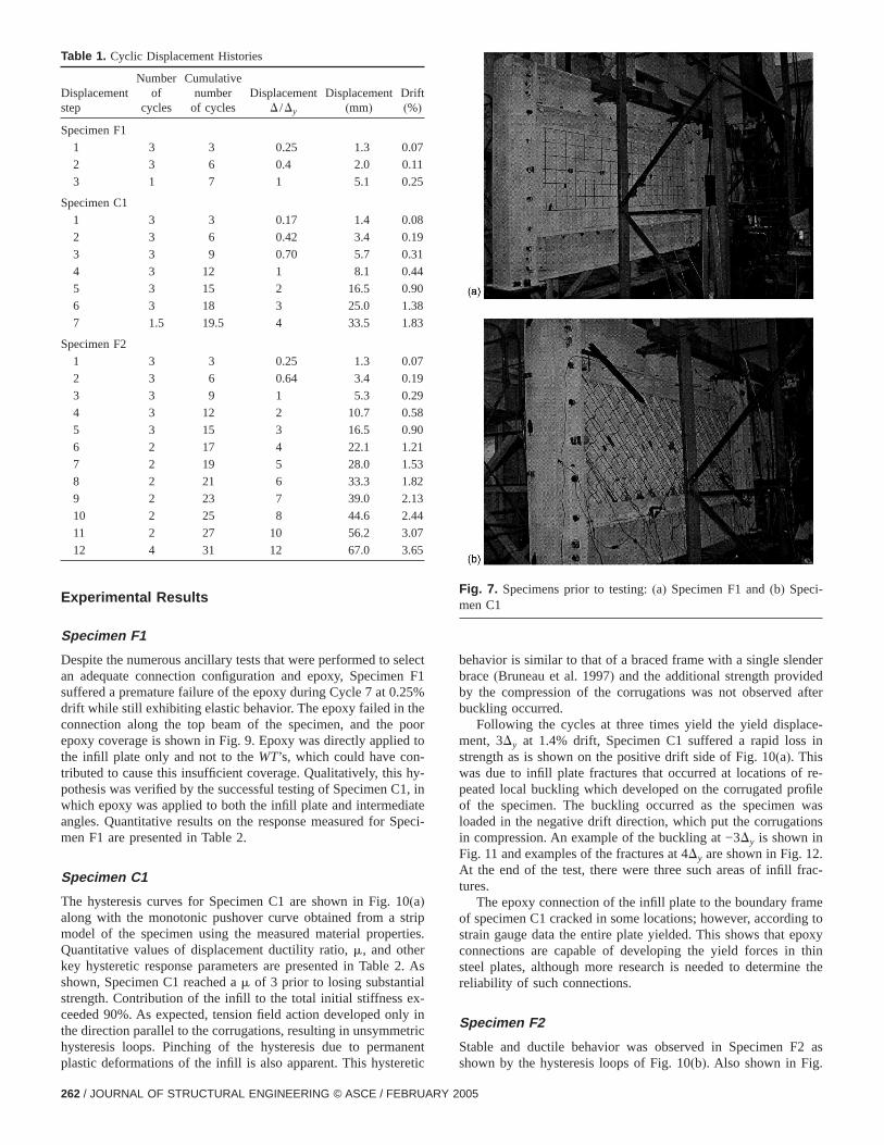
The test setup is shown in Fig. 6. Specimens are mountelarge clevises attached to a foundation beam, itself tensionthe strong floor of the SEESL. Lateral load was applied at thof the wall by a servocontrolled hydraulic actuator mountedtween the specimen and a reaction frame. The recommendeplied Technology Council(ATC) loading protocol of ATC 2(ATC 1992) was followed. Table 1 shows the displacementtory for each specimen and Figs. 7(a and b) show Specimens Fand C1 prior to testing.
Coupon tests of the infill material were performed andresulting stress–strain curves are shown in Figs. 8(a–c). Yieldstresses of 152, 214, and 330 MPa were obtained for specF1, F2, and C1. The material for specimens F1 and F2 was AA1008, which is a cold-rolled, carbon, commercial steel swith no mandatory mechanical properties. ASTM states thatcal yield stresses are between 140 MPa and 275 MPa(20 and40 ksi) and elongations at fracture of 20% in 50 mms2 in.d(ASTM 1997). The material for specimen C1 was ASTM A6Grade 33, which is a galvanized material with a minimum ystress of 230 MPas33 ksid and a minimum elongation at fractuof 20% in 50 mms2 in.d (ASTM 1998). Measured thicknessesthe infills were 0.91, 0.98, and 0.75 mm(0.0358, 0.0386, an0.0295 in.) for specimens F1, F2, and C1, respectively. Coutests of the boundary frames were not performed becausboundary frames were expected to remain elastic, but the mawas specified to be ASTM A572 Grade 50.
Fig. 5. Sections of infill of Specimen C1
Fig. 6. Test setup
OF STRUCTURAL ENGINEERING © ASCE / FEBRUARY 2005 / 261
selectn F1
25%hepoord to-hy-1, iniate
Speci
10striprties.
r2. A
alx-
nly inetricanent
nderedafter
ce-s in
f re-rofile
wasions
.frac-
meing topoxythin
ne the
2 as
3
4
7
5
Experimental Results
Specimen F1
Despite the numerous ancillary tests that were performed toan adequate connection configuration and epoxy, Specimesuffered a premature failure of the epoxy during Cycle 7 at 0.drift while still exhibiting elastic behavior. The epoxy failed in tconnection along the top beam of the specimen, and theepoxy coverage is shown in Fig. 9. Epoxy was directly appliethe infill plate only and not to theWT’s, which could have contributed to cause this insufficient coverage. Qualitatively, thispothesis was verified by the successful testing of Specimen Cwhich epoxy was applied to both the infill plate and intermedangles. Quantitative results on the response measured formen F1 are presented in Table 2.
Specimen C1
The hysteresis curves for Specimen C1 are shown in Fig.(a)along with the monotonic pushover curve obtained from amodel of the specimen using the measured material propeQuantitative values of displacement ductility ratio,m, and othekey hysteretic response parameters are presented in Tableshown, Specimen C1 reached am of 3 prior to losing substantistrength. Contribution of the infill to the total initial stiffness eceeded 90%. As expected, tension field action developed othe direction parallel to the corrugations, resulting in unsymmhysteresis loops. Pinching of the hysteresis due to perm
Table 1. Cyclic Displacement Histories
Displacementstep
Numberof
cycles
Cumulativenumber
of cyclesDisplacement
D /Dy
Displacement(mm)
Drift(%)
Specimen F1
1 3 3 0.25 1.3 0.07
2 3 6 0.4 2.0 0.11
3 1 7 1 5.1 0.25
Specimen C1
1 3 3 0.17 1.4 0.08
2 3 6 0.42 3.4 0.19
3 3 9 0.70 5.7 0.31
4 3 12 1 8.1 0.44
5 3 15 2 16.5 0.90
6 3 18 3 25.0 1.38
7 1.5 19.5 4 33.5 1.8
Specimen F2
1 3 3 0.25 1.3 0.07
2 3 6 0.64 3.4 0.19
3 3 9 1 5.3 0.29
4 3 12 2 10.7 0.58
5 3 15 3 16.5 0.90
6 2 17 4 22.1 1.21
7 2 19 5 28.0 1.53
8 2 21 6 33.3 1.82
9 2 23 7 39.0 2.13
10 2 25 8 44.6 2.4
11 2 27 10 56.2 3.0
12 4 31 12 67.0 3.6
plastic deformations of the infill is also apparent. This hysteretic
262 / JOURNAL OF STRUCTURAL ENGINEERING © ASCE / FEBRUARY 2
-
s
behavior is similar to that of a braced frame with a single slebrace(Bruneau et al. 1997) and the additional strength providby the compression of the corrugations was not observedbuckling occurred.
Following the cycles at three times yield the yield displament, 3Dy at 1.4% drift, Specimen C1 suffered a rapid losstrength as is shown on the positive drift side of Fig. 10(a). Thiswas due to infill plate fractures that occurred at locations opeated local buckling which developed on the corrugated pof the specimen. The buckling occurred as the specimenloaded in the negative drift direction, which put the corrugatin compression. An example of the buckling at −3Dy is shown inFig. 11 and examples of the fractures at 4Dy are shown in Fig. 12At the end of the test, there were three such areas of infilltures.
The epoxy connection of the infill plate to the boundary fraof specimen C1 cracked in some locations; however, accordstrain gauge data the entire plate yielded. This shows that econnections are capable of developing the yield forces insteel plates, although more research is needed to determireliability of such connections.
Specimen F2
Stable and ductile behavior was observed in Specimen F
Fig. 7. Specimens prior to testing:(a) Specimen F1 and(b) Speci-men C1
shown by the hysteresis loops of Fig. 10(b). Also shown in Fig.
005

tripinitialchediorre-oxi-ingec be-ving
t theg
thatd theinilarf the
ismicaviorry tousingl. The
the
celiasmi-
d is
nedrce–. 15.rce–
10(b) is the monotonic pushover curve obtained from a smodel of the specimen. Reasonable agreement in terms ofstiffness and yield base shear are evident. Specimen F2 reaductility ratio of 12 and drift of 3.7%, as shown in Table 2, prto losing significant strength. Additionally, from the data psented in Table 2, the infill of Specimen F2 contributed apprmately 90% of the initial stiffness of the system. The pinchexhibited by the hysteresis loops of Fig. 10(b) is again due to thaccumulation of nonrecoverable plastic strains, a hysteretihavior comparable to that of a concentrically braced frame ha
Table 2. Hysteretic Properties of Test Specimens
Specimen
Total initialstiffness(kN/mm)
Initialstiffness
without BF(kN/mm)
Yield baseshear(kN)
F1 84 73 372
C1 93 86 518
F2 106 96 364
Fig. 8. Infill coupon test results(a) Specimen F1(b) Specimen F2(c)Specimen C1
Note: BF5Bounddary Frame, NA5Not Applicable.
JOURNAL
a
slender braces. Fig. 13 shows the buckling of the infill plate apeak displacement of cycle 20s6Dyd, and the residual bucklinobserved after unloading from that displacement.
Ultimate failure of Specimen F2 was due to fracturespropagated from the endpoint of the welds that connecteinfill to the intermediateWT’s. The progression of the fracturethe lower south corner of the infill is shown in Fig. 14. Simfractures and propagation were observed in all four corners oinfill.
Boundary Frame Modeling
To further assess the adequacy of the light-gauge infills as seretrofit alternatives, it is necessary to separate the infill behfrom the boundary frame behavior. To do this, it is necessamodel the hysteretic behavior of the bare-boundary frame,results of bare-boundary frame testing to calibrate the moderesults of that model can then be numerically subtracted fromexperimental data.
Cook (1983) and Goto et al.(1991) used the bounding surfamodel with internal variables, originally formulated by Dafaand Popov(1976), to represent the hysteretic behavior of serigid frames. A summary of the model and how it is appliegiven in Chen et al.(1996) and is briefly reviewed here.
The bounding surface model with internal variables is defiin incremental form as either a moment–rotation or a fodisplacement relationship and is shown schematically in FigBecause it is to be calibrated and used with hysteretic fodisplacement curves, it takes the form:
ieldlacementmm)
Maximumdrift(%) m
Totalenergy(kN/m)
Energy-infillonly
(kN/m)
4.6 0.25 1 NA NA
8 1.4 3 73 50
5.3 3.7 12 444 212
Fig. 9. Poor epoxy coverage(Specimen F1)
Ydisp
(
OF STRUCTURAL ENGINEERING © ASCE / FEBRUARY 2005 / 263

ehes
c
ment
ecur-tthat
derhichent.
um
theri-e;
nextff-
sesodel
yyhealong
atal was
daryrdeded on. 17thenesult-lls
totalwere
6
1
DF = RktDd s2d
where DF=incremental base shear;Rkt=tangent stiffness at thcurrent displacement; andDd=incremental displacement. Ttangent stiffness at the current displacement is expressed a
Rkt =RkiRkp
Rki + Rkps3d
whereRki=initial stiffness of the system; andRkp=tangent plastistiffness at a given displacement and is calculated as
Rkp = Rb + hS d
din − dD s4d
where Rb=slope of the bounding lines with force interceptRbf
and is calibrated to asymptotically match the largest displaceexcursions in the observed results;h=hardening parameter(usedto fit the model to the experimental data); d=distance from thcurrent force to the corresponding bound in the direction ofrent loading; anddin=value ofd at the initiation of loading or aevery load reversal. This model is designed to provide curvesasymptotically approach the specified bound lines.
It was found necessary to modify this model slightly in orto capture changes in the initial stiffness of each cycle in wthe peak displacement was larger than initial yield displacemA linear change in initial stiffness with respect to the maximdisplacement of a cycle was defined as follows:
Table 3. Bounding Surface Model Parameters
Boundaryframe
Rbf
(kN)Rb
(kN/mm) h
BF1 90 3 100
BF2 75 3 25
Fig. 10. Specimen hystereses and pushover curves(a) Specimen Cand (b) Specimen F2
264 / JOURNAL OF STRUCTURAL ENGINEERING © ASCE / FEBRUARY 2
Rki = RkiiaSdmax
dy+ bD s5d
whereRkii =initial stiffness prior to any displacement reachingyield displacement;a and b=parameters used to fit the expemental data;dy=initial yield displacement of the boundary framand dmax=the maximum displacement reached during thecycle of loading. Additionally, a limit of 2.5 times the initial stinesssRkiid was placed onRki.
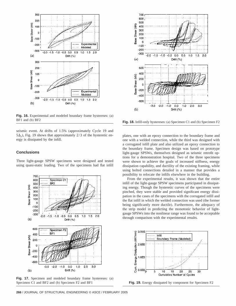
Figs. 16(a and b) show the experimentally obtained hystereand the results of the application of the bounding surface mwith internal variables described above, for BF1(the boundarframe used in Specimens F1 and F2) and BF2 (the boundarframe used in Specimen C1), respectively. The values for tparameters used in each model are presented in Table 3,with the percent error in cumulative energy dissipated(found bynumerically integrating both the experimental and modeled d).Note that in both cases the error is less than 10%. The modeimplemented in MatLab(MathWorks 1999).
Energy Dissipation by the Infills
Using the model described above, the behavior of the bounframes could be predicted for the displacement history recoduring the testing of the specimens. The results, superimposthe hystereses of Specimen C1, and F2, are shown in Figs(aand b), respectively. The boundary frame contributions canbe directly subtracted from the total specimen hystereses, ring in Figs. 18(a and b), representing the contribution of the infialone to the hysteretic behavior.
Using the hystereses of the infills only, as well as thehystereses of the specimens, the values reported in Table 3
m)dy
(mm) a b
Errorin energydissipated
(%)
64 13.5 0.67 0.42 9.71
6 13.5 0.67 0.42 –3.7
Fig. 11. Global and local buckling of Specimen C1 at −3Dy of Cycle16
Rki
(kN/m
10.
14.4
005

ensated
d ford forg dues the
F2.thanhicheseajor
n
JOURNAL
found. As mentioned before, the initial stiffness of the specimwas largely due to the infills. Furthermore, the energy dissipby the infills corresponds to 2/3 of the total energy dissipateSpecimen C1 and almost 1/2 the total energy dissipateSpecimen F2. The latter of these two is somewhat misleadinto the large drifts reached by Specimen F2. Fig. 19 showcumulative energy dissipated by component for SpecimenFrom this figure, it is apparent that the infill dissipates more50% of the total energy dissipated until about Cycle 28, wcorresponds to a ductility ratio of 12 and drift of 3.7%. Thdrifts exceed what would be expected for SPSW during a m
pecimen F2(a) 3Dy; (b) 6Dy; (c) 8Dy; and (d) 10Dy
Fig. 15. Schematic of bounding surface model(adapted from Cheet al. 1996)
Fig. 12. Examples of infill fractures at 4Dy Specimen C1
Fig. 13. Infill buckling of Specimen F2:(a) at 6dy and(b) at zero loadafter 6dy
Fig. 14. Fracture propagation-Lower south corner-S
OF STRUCTURAL ENGINEERING © ASCE / FEBRUARY 2005 / 265
den-
testedinfill
andwithn to
totypefit op-
ensnergyilees a
ntireipat-were
dissi-ll and
ofht-ptable
s:
:
2
seismic event. At drifts of 1.5%(approximately Cycle 19 an5Dy), Fig. 19 shows that approximately 2/3 of the hystereticergy is dissipated by the infill.
Conclusions
Three light-gauge SPSW specimens were designed andusing quasi-static loading. Two of the specimens had flat
Fig. 16. Experimental and modeled boundary frame hysterese(a)BF1 and(b) BF2
Fig. 17. Specimen and modeled boundary frame hystereses(a)Specimen C1 and BF2 and(b) Specimen F2 and BF1
266 / JOURNAL OF STRUCTURAL ENGINEERING © ASCE / FEBRUARY 2
plates, one with an epoxy connection to the boundary frameone with a welded connection, while the third was designeda corrugated infill plate and also utilized an epoxy connectiothe boundary frame. Specimen design was based on prolight-gauge SPSWs, themselves designed as seismic retrotions for a demonstration hospital. Two of the three specimwere shown to achieve the goals of increased stiffness, edissipation capability, and ductility of the existing framing, whusing bolted connections detailed in a manner that providpossibility to relocate the infills elsewhere in the building.
From the experimental results, it was shown that the einfill of the light-gauge SPSW specimens participated in dissing energy. Though the hysteretic curves of the specimenspinched, they were stable and provided significant energypation in the cases of the specimens with the corrugated infithe flat infill in which the welded connection was used(the formerbeing significantly more ductile). Furthermore, the adequacythe strip model in predicting the monotonic behavior of liggauge SPSWs into the nonlinear range was found to be accethrough comparison with the experimental results.
Fig. 18. Infill-only hystereses:(a) Specimen C1 and(b) Specimen F
Fig. 19. Energy dissipated by component for Specimen F2
005

d aonswastheinfill
urredngwastheto
turesges ongth
eringationterions,
thisct the
c
car-g
-ls,
fuild-r.of
f
f
f
f
deroul-
r-
gn-
f
ings-
-ns.”
tite
.,
akeou-
a.te
ls-
Buf-
The ultimate failure mode of the specimen which utilizecorrugated infill was found to be fracture of the infill at locatiof repeated local buckling and an industrial strength epoxyfound to be an adequate material to connect the infill toboundary frame in this case. For the specimen using the flatand an epoxy connection to the boundary frame, failure occin the epoxy prior to yielding of the infill. The specimen utilizia flat infill and a welded connection to the boundary framesignificantly more ductile than the other two and failure wasresult of fractures in the infill adjacent to the fillet weld usedconnect the infill to the boundary frame. Despite these fracnear the welded connection, which appeared in the early stathe test, this specimen did not suffer a significant loss of streuntil 12 times the yield displacement.
Acknowledgment
This work was supported in whole by the Earthquake EngineResearch Centers Program of the National Science Foundunder Award No. ECC-9701471 to the Multidisciplinary Cenfor Earthquake Engineering Research. However, any opinfindings, conclusions, and recommendations presented inpaper are those of the writers and do not necessarily refleviews of the sponsors.
References
Applied Technology Council.(ATC). (1992). “Guidelines for seismitesting of components of steel structures.”Rep. No. 24, ATC, Red-wood City, CA 94065.
ASTM. (1997). “Standard specification for commercial steel sheet,bon, cold-rolled.”A 366/A 336M-97, American Society for Testinand Materials, Philadelphia.
ASTM. (1998). “Standard specification for steel sheet, zinc-coated(gal-vanized) zinc-iron alloy-coated(galvannealed) by the hot-dip process.”A 653/A 653M-98, American Society for Testing and MateriaPhiladelphia.
Berman, J. W., and Bruneau, M.(2003a). “Experimental investigation olight-gauge steel plate shear walls for the seismic retrofit of bings.” Tech. Rep. No. MCEER-03-0001, Multidisciplinary Center foEarthquake Engineering Research, Univ. at Buffalo, Buffalo, N.Y
Berman, J. W., and Bruneau, M.(2003b). “Plastic analysis and design
JOURNAL
f
steel plate shear walls.”J. Struct. Eng., 129(11), 1148–1156.Bruneau, M., Uang, C. M., and Whittaker, A.(1997). Ductile design o
steel structures, McGraw-Hill, N.Y.Caccese, V., Elgaaly, M., and Chen, R.(1993). “Experimental study o
thin steel-plate shear walls under cyclic load.”J. Struct. Eng., 119(2),573–587.
Canadian Standards Association(CSA). (2001). “Limit states design osteel structures.”CAN/CSA S16-01, Willowdale, Ontario, Canada.
Chen, W. F., Goto, Y., and Liew, J. Y. R.(1996). Stability design osemirigid frames, Wiley, N.Y.
Cook, N. E.(1983). “Strength of flexibly-connected steel frames unload histories.” PhD dissertation, Univ. of Colorado—Boulder, Bder, Colo.
Dafalias, Y. F., and Popov, E. P.(1976). “Plastic internal variables fomalism of cyclic plasticity.”J. Appl. Mech., 43, 645–651.
Driver, R. G., Kulak, G. L., Kennedy, D. J. L., and Elwi, A. E.(1997).“Seismic behavior of steel plate shear walls.”Structural EngineerinRep. No. 215, Dept. of Civil Engineering, Univ. of Alberta, Edmoton, Alberta, Canada.
Elgaaly, M., Caccese, V., and Du, C.(1993). “Postbuckling behavior osteel-plate shear walls under cyclic loads.”J. Struct. Eng., 119(2),588–605.
Federal Emergency Management Agency(FEMA). (1997). “NEHRPRecommended Provisions for Seismic Regulations for New Buildand Other Structures, Part-1-Provisions.”FEMA 302, Building Seismic Safety Council for the FEMA, Washington, D.C.
Goto, Y., Suzuki, S., and Chen, W. F.(1991). “Analysis of critical behavior of semirigid frames with or without load histories in connectioInt. J. Solids Struct., 27(4), 467–483.
Loctite. (2001). “Product description sheet-Hysol product 9460.” LocInc., Rocky Hill, Conn.
MathWorks.(1999). MatLab Function Reference, The MathWorks, IncNatick, Mass.
Rezai, M.(1999). “Seismic behavior of steel plate shear walls by shtable testing.” PhD dissertation, Univ. of British Columbia, Vancver, British Columbia, Canada.
Thorburn, L. J., Kulak, G. L., and Montgomery, C. J.(1983). “Analysisof steel plate shear walls.”Structural Engineering Rep. No. 107, Dept.of Civil Engineering, Univ. of Alberta, Edmonton, Alberta, Canad
Timler, P. A., and Kulak, G. L.(1983). “Experimental study of steel plashear walls.”Structural Engineering Report No. 114, Dept. of CivilEngineering, Univ. of Alberta, Edmonton, Alberta, Canada.
Yang, T. Y., and Whittaker, A.(2002). “MCEER demonstration hospitaMathematical models and preliminary results.”Tech. Rep., Multidis-ciplinary Center for Earthquake Engineering Research, Univ. atfalo, Buffalo, N.Y.
OF STRUCTURAL ENGINEERING © ASCE / FEBRUARY 2005 / 267