Embed Size (px)
Citation preview

1
Experimental investigation of horizontally operating thermal diode solar water heaters 1
with differing absorber materials under simulated conditions 2
Ronald Muhumuza*, Aggelos Zacharopoulos, Jayanta Deb Mondol, Mervyn Smyth, 3
Adrian Pugsley, Giovanni Francesco Giuzio, Danas Kurmis 4
Centre for Sustainable Technologies (CST), Belfast School of Architecture and the Built 5
Environment, Ulster University, Newtownabbey BT37 0QB, Northern Ireland, UK 6
Abstract 7
Partially evacuated spaces with small volumes of HTF (Heat Transfer Fluid) Phase Change 8
Materials (PCMs), called thermal diodes, can minimise heat losses in ICSSWHs. However, the 9
collection and retention performance of thermal diode ICSSWHs is material dependent as well 10
as influenced by environmental conditions. To investigate this condition, three laboratory scale 11
thermal diode ICSSWH prototypes were experimentally evaluated with different component 12
materials and volumetric capacity. The units were tested indoors under constant solar simulator 13
irradiance for 6 hours to determine heat collection, followed by an 18-hour cooling period to 14
determine heat retention. In addition, the water temperature in storage was raised to desired 15
levels using a refrigerated/heating circulator and prototypes left to cool overnight in stable 16
ambient air conditions. ICSSWH 1 with 16.7 litres of storage capacity, had absorber and 17
evaporator components of aluminium and stainless steel, respectively whilst ICSSWHs 2 and 18
3 had vessels made from stainless steel with 16.7 and 27.7 litres storage capacity, respectively. 19
The mean 6-hour collection efficiencies for ICSSWHs 1, 2 and 3 were 47.4%, 51.6% and 20
48.0%, respectively. Normalised water temperature profiles, retention efficiencies and thermal 21
loss coefficients suggest that the performance of ICSSWH 2 and ICSSWH 3, are preferable 22
compared to ICSSWH 1. 23
Keywords: Thermal-diode ICSSWHs, materials, PCMs, collection, retention, simulation 24
1. Introduction 25
Solar water heating remains thus far the most common way for harnessing solar thermal heat 26
with non-concentrating collectors i.e. conventional small-scale solar water collectors of 27
unglazed, flat plate and evacuated tube configurations playing a pivotal role. With a global 28
total installed capacity of 456 GWth, new installations declined by 4.2% during the period 2016 29
* Corresponding author.
E-mail address: [email protected] (R. Muhumuza)

2
to 2017 due to market pressure from heat pumps and photovoltaic systems in large markets of 1
China and Europe [1]. Such a decline is undesirable and is likely to have significant impact on 2
the achievement of global climate goals. Integrated Collector Storage Solar Water Heaters 3
(ICSSWHs) have the merit and potential to broaden the scope of current small-scale solar hot 4
water systems for single and multifamily dwellings, particularly in warm climates [2,3]. Their 5
continual development and improvement as simple, reliable and low cost configurations is 6
essential to achieve increased interest in the general solar heat market globally. 7
Past reviews [4–6] have documented the evolution and development of innovative ICSSWHs. 8
They typically experience significant heat losses during conditions of poor solar radiation and 9
their heat retaining capability during the night depends on the effectiveness of existing thermal 10
insulation measures. This problem could be significantly minimised by configuring a system 11
capable of achieving efficient forward operation during thermal energy collection and 12
inhibiting heat loss through some kind of characteristic reverse operation during the night. A 13
synergetic combination of a thermal diode mechanism and suppressed convective currents in a 14
greenhouse effect created by a transparent cover in concentric cylindrical vessels under the 15
trade name ‘SolaCatcher’ [7] is a promising configuration. A thermal diode is a mechanical 16
technique that enables rapid solar heat collection with thermal insulation of the collected heat 17
in a storage tank that minimises heat loss during the night and overcast periods. A small volume 18
of PCM typically water, resides in the evacuated annulus of two concentric cylindrical vessels 19
and determines the forward and backward operational behaviour of the thermal diode as 20
illustrated in Fig. 1. In the forward mode, radiant solar heat evaporates the PCM under partial 21
vacuum in the annulus, which then condenses on the outer surface of the storage 22
tank/evaporator thereby releasing its latent heat of vaporisation to the store before returning to 23
the sump [8]. In the reverse operation mode, the partial vacuum maintained in the annulus 24
minimises convective and radiative losses to the surface of the outer vessel in a manner 25
identical to the behaviour of a Thermos flask. 26

3
1
Fig. 1. Operating principle of the ICSSWH design concept [8]: (a) forward operation during 2 thermal energy collection for a sunny period, (b) reverse operation during overcast and the 3 night-time 4
The presence of non-condensable gases in the thermal diode cavity (as indicated by the cavity 5
pressure at a low temperature) significantly impairs the forward mode heat transfer rate [9,10]. 6
Evacuating the cavity to the lowest total pressure possible (ie saturation pressure of the working 7
fluid) eliminates non-condensable gases and in turn enables effective forward mode heat 8
transfer. In practice, the gas load and the vacuum pump capacity will determine the minimum 9
achievable cavity pressure. Gas load is likely to be dominated by water vapour and dissolved 10
non-condensable gases released from the reservoir, which supplies the water used to wet the 11
evaporator. Souliotis et al [11] experimentally investigated the initial annular vacuum gauge 12
pressure in a horizontally operating ICSSWH with asymmetric Compound Parabolic 13
Concentrating (CPC) reflector for which the thermal diode achieves the most optimal 14
behaviour. It was found that initial total vacuum pressures in the range between 670 ± 16 mbar 15
and 790 ± 18 mbar achieved optimal behaviour of the thermal diode in such systems. Similar 16
research for non-concentrating horizontally operating thermal diode ICSSWHs of the type 17
investigated in the current study is non-existent but deeper initial total vacuum pressures 18
reaching 990 ± 20 mbar may be necessary. Boreyko and Chen [10] showed that a low cavity 19
pressure could be achieved by applying a primary vacuum with no PCM present, adding the 20
PCM through a syringe, then applying a secondary vacuum to remove any dissolved non-21
condensable gases. It can be hypothesised that a simpler but equally effective evacuation 22
technique might be to add water to the cavity and progressively chill it whilst evacuation takes 23
place [12]. 24
(a) (b)
PCM liquid (water)
Absorber vessel
Inner storage vessel
Heated water in store
Evacuated annulus
Outer transparent cover

4
The thermal performance assessment of vertically operating prototypes of the ‘SolaCatcher’ 1
was performed by Smyth et al [13,14] who found average 6 hour collection and 18 hour thermal 2
retention efficiencies reaching 36% and 60% respectively. Vertical installations are preferred 3
for achieving thermal stratification in the storage tank, which is often a requirement for 4
cold/temperate climate conditions in northern regions [15]. However, horizontally operating 5
units could be satisfactory in regions with significant solar resources. This article develops and 6
experimentally demonstrates the performance characteristics of horizontally operating thermal 7
diode ICSSWHs by considering differences in vessel material and volumetric capacity. To 8
report this research, the remaining sections present the following: Section 2 introduces the 9
design concept of the typical laboratory scale horizontally operating ‘Solar Catcher’, 10
investigates the question of selecting suitable materials for key components and offers an 11
estimation of prototype cost. Section 3 describes experimental facilities and attendant 12
instrumentation methodologies. Section 4 provides physical models utilised in processing 13
experimental data. Section 5 presents experimental results, Section 6 discusses important 14
considerations concerning the reported experimental results; and Section 7 delivers the overall 15
conclusion and draws attention to unanswered questions. 16
2. ICSSWH components and material considerations 17
Component materials have a bearing on the performance characteristics of the proposed 18
horizontally operating thermal diode ICSSWH prototypes. Potential health and environmental 19
hazards involved in prospective technologies are also important. Existing standard 20
requirements for components of solar thermal collectors [16] do not address ICSSWHs. A 21
quick search using the web-based database of the Solar Rating & Certification Corporation 22
[17] reveals that few Original Equipment Manufacturer (OEM) companies are filling technical 23
specifications and performance ratings for simple commercial ‘Integrated Collector Storage 24
(ICS) glazed’ technologies and technical specification sheets suggest that their component 25
materials maintain typical material choices in traditional solar water heaters. This makes the 26
Research and Development (R&D) process of novel laboratory scale horizontally operating 27
thermal diode ICSSWHs prototypes speculative particularly when selecting materials for key 28
collector components. Therefore, in the fabrication phase, a consideration of materials is as 29
important in laboratory scale prototypes as it is in commercially ready systems due to 30
performance, economic, health and environmental constraints. 31

5
2.1. General thermal diode ICSSWH components 1
This section describes the structural concept of the horizontally operating thermal diode 2
ICSSWH by use of a hierarchical component layout approach. When describing the technical 3
composition of any technology, it is important to utilise an approach that enables the tracking 4
of involved labour and material resources for the effective management of the product life 5
cycle. One such approach is a product-oriented Work Breakdown Structure (WBS) [18]. It 6
subdivides the basic horizontally operating thermal diode ICSSWH concept into a hierarchy of 7
its physical elements as illustrated by Fig. 2 and reveals all collector components for effective 8
management of the R&D process. 9
10
Fig. 2. Work breakdown structure of a horizontally operating thermal diode ICSSWH unit 11
The concentric solar radiation-absorbing vessel and the water tank (see dotted boxes in colour) 12
are crucial in defining the performance, appearance, strength, durability and affordability of 13
the fabricated prototypes. These requirements must balance with achieving a long-lasting and 14
efficient solar energy-collecting device [19]. Sealant/adhesive materials and insulation are 15
prone to moisture attack leading to accelerated degradation of collector performance [20]. 16
Furthermore, the life cycle performance of systems is increasingly becoming an important 17
aspect of the R&D process particularly the need to cut on the global demand of metallic 18
materials [21,22]. As a result, alternative non-metallic materials such as polymers are under 19
investigation [23,24]. Materials forming the concentric absorber and hot water storage vessels 20
in the thermal diode ICSSWH could be of significance to the overall performance of the device. 21
Basic thermal diode ICSSWH
End caps
inlet/outlet piping & ports
Inner groove
Middle groove
Outer groove
Vacuum port
InsulationConcentric
vessels
Transparent cover
Retaining screws
Absorber
Black paint
Adhesive
Water tank
Adhesive
Thermal diode
PCM liquid
Capillary matting

6
2.2. Absorber and water storage vessel material considerations 1
Fulfilling the horizontally operating thermal diode ICSSWH prototypes encompasses the 2
identification of materials for the fabrication of the absorber and the water storage vessels. 3
Lenel and Mudd [25] reviewed materials for fabricating low temperature solar water heaters. 4
Besides achieving a significant thermal performance, criteria must address issues relating to 5
the environment in which the fabricated components are to function. During the day, the black 6
coated outer solar radiation-receiving surface of the absorber vessel operates under solar heat 7
trapped beneath the transparent cover. In addition, a portion of the inner absorber surface is in 8
constant contact with the PCM vapour material, which wets the remaining surface when the 9
thermal diode is in forward mode. At the same time, the PCM vapour constantly condenses on 10
the outer surface of the water storage vessel whilst the inner surface is in constant contact with 11
hot water. The inner storage vessel should also withstand the pressure exerted by the water 12
mains supply. 13
Component materials should also withstand any adverse physical phenomena existing in the 14
atmospheric operating environment. Material surfaces of the absorber and storage tank vessels, 15
which interface with the annulus, must be resistant to the destructive pull of vacuum pressure. 16
They should also be corrosion resistant, of low weight to volume ratio, affordable and easy to 17
fabricate. One fundamental engineering consideration in eliminating avoidable corrosion such 18
as galvanic corrosion is to prevent any contact of different metallic materials. Reinhart and 19
Jenkins [26] give detailed corrosion control ideas concerning the design of water handling 20
materials. However, proof-of-concepts for laboratory testing such as those investigated in the 21
current report may not have such stringent measures since the operating life of prototypes is 22
not an extremely important consideration. An exhaustive understanding of existing materials 23
must precede a thermally efficient and environmentally benign thermal diode ICSSWH 24
product. Stainless steel, aluminium and copper are perhaps the most prevalent materials for 25
engineering of solar energy systems. Therefore, when dealing with the design of low cost 26
laboratory scale prototypes, one often finds it necessary to decide between these three. Table 27
1 provides important material attributes along with advantages and disadvantages associated 28
with the three common materials. 29
Sheet metal materials provide flexibility and capability for fabricating a wide range of absorber 30
vessel and water tank diameters. To produce the cylindrical vessels, one cuts the sheet metal to 31
the required dimensional length, folds it and joins the two end widths using a suitable welding 32

7
technique. The possible range of standard dimensions available in the market is extensive and 1
maximum vessel diameters in the range ~637-955 mm per metal sheet are possible. However, 2
one only needs sheet metal material sufficient for the prototype size in mind. Copper is superior 3
in terms of thermal conductivity followed by aluminium. However, this also implies that the 4
two materials can experience significant heat losses while in operation. Whilst stainless steel 5
may show performance differences, a study by Shariah et al [27] found that there is likely to 6
be no significant performance difference in choosing between aluminium and copper for flat 7
plate absorbers. Stainless steel and copper could be advantageous due to their high density and 8
specific heat, which directly contributes to the system thermal mass albeit with a system weight 9
penalty. Changing ambient and operating temperatures introduce constraints on materials and 10
practical mechanical design, necessitating adequate measures to address thermal expansion. 11
For example, the values of linear coefficients of thermal expansion shown in Table 1 indicate 12
that a 1-meter long vessel can experience an elongation of 1 mm under a temperature change 13
of 43°C, 59°C and 63°C, if fabricated using aluminium, copper and stainless steel, 14
respectively. Volume coefficients of thermal expansion are three times greater than linear 15
coefficients of thermal expansion [28]. Thermal expansion and contraction have important 16
limitations in ICSSWHs [3], and could compromise reliability of vacuum pressure in thermal 17
diode configurations. 18
Conclusive material selection decisions for market ready concepts also considers ecological 19
impacts and economic viability of the final product. On the one hand, assessment of the 20
ecological aspect considers system environmental and energy balances through a detailed Life 21
Cycle Assessment (LCA). This combines carbon dioxide (CO2) emissions as well as embodied 22
energy (direct and indirect energy requirements) in extracting and producing raw materials; 23
producing, installing, maintaining and disposing the product along with transportation 24
requirements occurring within these activities [29]. In one LCA study, Kalogirou [30] found 25
that, the percentage environmental savings of coupling a domestic solar hot water and/or space 26
heating collector with conventional electrical and/or diesel backup improved environmental 27
savings by up to 80%. In addition, Rey-Martínez et al [31] found through a complete LCA 28
study that solar water heaters coupled with modern efficient gas boilers would be 29
environmentally ideal in domestic applications. Copper has the highest embodied energy of 30
70.6 MJkg−1 (631,160 MJm−3) followed by aluminium with 191 MJkg−1 (515,700 MJm−3) 31
[32]. Although a detailed environmental and embodied energy analysis is beyond the scope of 32
this work, this information is indicative of the likely impact of each material to the overall 33
8
environmental and energy balance of the completed product. On the other hand, customers are 1
more likely to acquire an ICSSWH that is low cost as opposed to being only environmentally 2
sustainable [33]. Therefore, material cost is an important consideration in market ready 3
technologies, as well as laboratory scale prototypes. Of the three materials, aluminium is the 4
cheapest. Stainless steel has a moderate cost per kg almost comparable to aluminium and offers 5
long operating life. Copper is the most expensive of the three materials with relative cost 6
reaching $USD 10.1 per kg compared to $USD 4.9 per kg for stainless steel and $USD 4.7 per 7
kg for aluminium [28]. 8
There is also important technical considerations regarding material contribution to the total 9
weight of prototypes. Copper has the highest mass to volume ratio, which is three times greater 10
than that of aluminium but almost comparable to stainless steel. Since ICSSWHs tend to 11
contain large volumes of water in the thermal store, one should observe the added weight 12
penalty associated with the use of heavy components. In this respect, aluminium is the most 13
favourable material in terms of achieving a lightweight system. In light of all the above 14
considerations, the study adopted stainless steel and aluminium to fabricate the three prototypes 15
and to enable an evaluation of material related performance differences. Section 2.3 provides 16
the physical and structural details concerning the investigated prototypes. 17

9
Table 1 1 Technical properties and evaluation of common materials used in solar thermal engineering [28,32,34] 2
Description Stainless steel Copper Aluminium
Thermal conductivity (Wm−1K−1) 15.9 388 180
Density (kgm−3) 8000 8795 2700
Specific heat (Jkg−1K−1) 502 385 896
Coefficient of thermal expansion (°C−1) 16.0 × 10⁻⁶ 17.0 × 10⁻⁶ 23.6 × 10⁻⁶
Embodied energy, MJkg−1, (MJm−3) 32.0, (251,200) 70.6, (631,160) 191, (515,700)
Cost ($USD/kg) 1.50-7.25 6.50-10.00 2.00-7.70
Relative cost ($USD/kg)a 4.9 10.1 4.7
Metal sheet thickness ranges (mm) ~0.7-3.0 ~0.4-3.0 ~0.5-6.0
Possible range of standard lengths (mm) ~2000-3000 ~2000-3000 ~2000-3000
Possible range of standard widths (mm) ~1000-1500 ~600-1000 ~1000-1500
Max. achievable vessel diameters (mm) ~637-955 ~637-955 ~637-955
Advantages
Easy formability and weldability Durable Low cost
Safe in most environments, passive
(cathodic) Significant thermal mass
Safe in most
environments, neutral
(anodic)
Good thermal mass Can inhibit growth of pathogens
e.g. Pneumophila legionella
Light weight with high
thermal losses
Hygienic and aesthetic appearance Good thermal mass Easily formable
Long life makes it cost-effective - -
Disadvantages
Can corrode aluminium in saline
environments Very expensive Low thermal mass
- Moderately active (cathodic), can
corrode aluminium Loses heat easily
- Loses heat easily -
3
a Prices refer to 2016 averages cited in ref [28], but are highly fluctuating. For instance, the average manufacturing price of copper as per second quarter of 2017 is estimated
at US$5.61/UK£4.34 per kg [35].

10
2.3. Design concept of the horizontal thermal diode ICSSWH prototypes 1
The forward and reverse operating strategies captured in Fig. 1 combine along with the WBS 2
outlined in Fig. 2 to enable the conceptualisation of a horizontal ICSSWH shown in Fig. 3. 3
The outermost transparent cover suppresses convective heat losses to the ambient while 4
outlining the general physical appearance of the ICSSWH. The concentric absorbing vessel 5
underneath the transparent cover absorbs incident solar radiation. The innermost concentric 6
cylinder is the storage vessel. The annulus between the storage vessel and the absorber 7
constitutes the thermal diode. Inlet/outlet ports provide water access points, the end covers 8
provide sealing mechanisms and insulation minimises heat loss at either ends of the ICSSWH 9
collector. Three prototypes were fabricated in order to examine system size (capacity) and 10
material related performance differences in the thermal diode ICSSWH. The geometrical 11
characteristics and material choices for the three ICSSWH prototypes are summarised in Table 12
2 and Table 3 (section 2.4), respectively. 13
14
Fig. 3. General concept of the horizontally operating thermal-diode ICSSWH 15
Absorber vessel
Annulus
Storage vessel
End cover
Lid with external pipe
connecting adapter
fitting
Outermost transparent cover
Insulation

11
Table 2 1 Concentric vessel dimensional characteristics and geometrical characteristics 2
Description ICSSWH 1 ICSSWH 2 ICSSWH 3
Diameters (mm)
Storage vessel 150 150 150
Absorber vessel 200 200 200
Transparent cover 244 244 244
Geometrical characteristics
Common vessel length (m) 1.00 1.00 1.65
Inner vessel storage volume (L) 16.7 16.7 27.7
Prototype gross area (m2) 1.38 1.38 2.13
2.4. Material selection for the water tank and absorber and cost considerations 3
Cost considerations are an important aspect in the selection of various materials for fabricating 4
the thermal diode ICSSWH prototypes. Other aspects include material suitability to the 5
incumbent application and commercial availability. Concerning the outermost transparent 6
cover that forms a concentric aperture, a low cost and widely available 1 mm thick flexible 7
Polyethylene Terephthalate Glycol (PETG) sheet of high transmissivity (𝜏 ≅ 0.90) was 8
adopted. Prototype dimensions proposed in Table 2 enabled the estimation of the quantity of 9
metallic materials for fabricating the water tank and the absorber. For each prototype, stainless 10
steel formed the innermost water storage tank due to its satisfactory performance in wet 11
environments, availability in a wide range of thicknesses and cost effectiveness. Then the total 12
cost of metallic materials ensued from three alternative materials for fabricating the absorber 13
vessel by considering current retail prices excluding Value Added Tax (VAT). Fig. 4 compares 14
the cost excluding VAT of alternative metallic material choices to fabricate the water tank and 15
the absorber vessel. Choosing aluminium (AL) for the absorber vessel as opposed to stainless 16
steel (SS) and copper (CU) lowers the total cost of metallic materials in each prototype by at 17
least 39% and 68% respectively. These considerations guided final material choices for three 18
prototypes summarised in Table 3. 19

12
1
Fig. 4. Comparison of material costs for fabrication of water tank and absorber vessels with 2 estimated retail prices in £/kg of 4.10, 6.15 and 14.40 for aluminium, stainless steel and copper 3
respectively 4
Table 3 5 Material selection for concentric components of the fabricated ICSSWH prototypes 6
Concentric
components Description ICSSWH 1 ICSSWH 2 ICSSWH 3
Storage
vessel
Material Stainless steel Stainless steel Stainless steel
Thickness (mm) 1.5 1.5 1.5
Absorber
vessel
Material Aluminium Stainless steel Stainless steel
Thickness (mm) 2 1.5 1.5
Transparent
cover
Material PETG PETG PETG
Thickness (mm) 1 1 1
Total prototype mass (kg) 39.5 47.7 61.2
The water tanks and solar radiation-absorbing vessels in ICSSWH 1 are made of stainless steel 7
and aluminium respectively, while they are both of stainless steel in ICSSWH 2 and ICSSWH 8
3. ICSSWH 1 and ICSSWH 2 are geometrically identical (1.0 m) whilst ICSSWH 3 is 1.65 m 9
in length. Aluminium plates integrated on the outer surface of the acrylic end covers for 10
ICSSWH 1 and ICSSWH 2 support the inlet and outlet connections. ICSSWH 3 had slight 11
modifications in the acrylic end cover but of no importance to performance. A 50 mm thick 12
insulating polystyrene foam minimised prototype heat losses from end covers. The outer 13
surface of the concentric solar radiation-absorbing vessel had matt black coating with 14
absorptivity (𝛼 ≅ 0.92), emissivity (𝜀 ≅ 0.90) and reflectivity (𝜌𝑟 ≅ 0.1). The two acrylic 15
end-covering blocks possess three concentric grooves that fit and retain concentric cylinders 16
with the help of silicone adhesive. 17
49.57
81.22
154.99
255.16
82.01
134.74
0.00
50.00
100.00
150.00
200.00
250.00
300.00
ICSSWH 1&2 ICSSWH 3
Co
st (
£)
SS tank & AL absorber
SS tank & CU absorber
SS tank & SS absorber

13
To conclude, Table 4 provides a cost breakdown of fabricating the individual prototypes. The 1
total material and labour cost to fabricate the three ICSSWH prototypes (excluding VAT) was 2
calculated as UK £309.51, 319.16 and 380.31 for ICSSWH 1, 2 and 3 respectively. Since 3
operations of fabricating few ICSSWH prototypes do not leverage economies of large-scale 4
production, this cost is acceptable at concept level. An appropriate economic investigation of 5
the presented thermal diode ICSSWH prototypes should cover their anticipated operating life 6
for specified performance requirements of the optimised system. Nevertheless, an appreciation 7
of the total cost per prototype is an early indicator of economic feasibility of the fabrication 8
techniques employed to realise the proposed technical concept.9

14
Table 4 1 Breakdown of unit fabrication costs of the ICSSWHs for mass production 2
Components Description Unit Cost/unit
(£)
Estimated cost
ICSSWH
1
ICSSWH
2
ICSSWH
3
Concentric
vessels
770 mm long Polyethylene Terephthalate Glycol (PETG) sheet,
1 mm thickness £/m 30.00 23.00 23.00 23.00
5.7, 13.2, 21.8 kg of stainless Steel for ICSSWH 1,2&3 resp. £/kg 6.15 34.77 81.14 133.88
3.6, 0.4, 0.4 kg of aluminium for ICSSWH 1,2&3 resp. £/kg 4.10 14.79 1.74 1.74
1/2 , 1/2, and 3/4 bottle of Matt Black absorber coating for
ICSSWH 1,2&3 resp. £/bottle 3.09 1.54 1.54 2.32
1/2 tube silicone adhesive £/tube 6.11 3.06 3.06 3.06
End Caps Two, 20 mm acrylic sheet with inner, 10 mm deep middle and
outer concentric grooves, 300 mm x 300 mm £/each 9.85 19.70 19.70 19.70
Two 15 mm dia. straight coupling, copper (inlet/outlet ports) £/each 2.30 4.59 4.59 4.59
Various compression fittings, screws and bolts various - 8.50 8.50 8.50
Two 15 mm dia. Pegler Yorkshire Ball Isolating Valve, Brass £/each 4.5 9.00 9.00 9.00
0.5 m length15mm copper pipe £/m 1.30 0.65 0.65 0.65
Insulation Two, 50 mm thick, Polystyrene insulation 150 mm x 150 mm £/m2 4.36 8.72 8.72 8.72
0.5 m length, 20 mm thick, 15 mm pipe insulation £/m2 2.76 1.38 1.38 1.38
Capillary matting 0.6, 0.6, 1 m2 for ICSSWH 1,2&3 of fibreglass plain weave £/m2 1.06 0.64 0.64 1.01
0.6, 0.6, 1 m2 for ICSSWH 1,2&3 of multipurpose welded wire
mesh £/m2 3.82 2.29 2.29 3.64
Total material cost (excluding VAT) 132.64 165.94 221.18
Fabrication/assembly
cost
Labour hours 7.48, 6.48 and 6.73 for ICSSWH 1, 2 and 3
respectively. Man hour rate based on a notional twelve man
gang of 12 men for Northern Ireland (0.75 x 31.55£/man hour in
London) [35]
£/h 23.66 176.88 153.21 159.13
Total unit cost (excluding VAT and tool amortization cost) 309.51 319.16 380.31
3

15
3. Experimental facilities and instrumentation methodology 1
3.1. Heat loss testing preceded by use of a refrigerated/heating circulator 2
Heat loss testing involved filling the inner storage vessel of the ICSSWH with hot water 3
followed by a cooling period under stable ambient conditions with no solar irradiance [36]. 4
Fig. 5 is the general schematic of the experimental test rig. A refrigerated/heating circulator 5
(Julabo FP 50) supplied hot water into each ICSSWH prototype until a desired temperature 6
was attained. An improvised system vent pipe on each ICSSWH variant allowed the complete 7
removal of all air bubbles from within the tank and bringing the tank to full capacity. The inlet 8
pipe valve (#8) and the outlet pipe value (#9) allowed the disconnection of the 9
refrigerated/heating circulator. The experimental setup for one of the prototypes under 10
independent retention testing is shown in Fig. 6. The water temperature in the storage vessel 11
was raised to 55 ± 0.5°C for ICSSWH 1, 60 ± 0.5°C for ICSSWH 2 and 50 ± 0.6°C for 12
ICSSWH 3 before disconnecting the refrigerated/heating circulator and leaving the prototypes 13
to independently cool naturally in ambient environment. Here, continuous measurements of 14
ambient air temperature and water temperature were also collected by connecting the 15
thermocouples to a data logger (Delta-T DL2e), which sampled every 5 seconds and recorded 16
average temperatures on a 1-minute interval for a total testing period of 18 hours. The 17
experiments simulated the behaviour of the devices under no draw off operation. 18

16
1
Fig. 5. Experimental setup schematic for whole system evaluation of ICSSWH variants: 1. SolaCatcher with transparent cover and end insulation, 2
2. Vacuum shutoff valve, 3. Pressure gauge, 4. Vacuum pump isolation valve, 5. Vacuum pump (oil rotary vane single-stage), 6. System degassing 3 valve, 7. Julabo FP 50, 8. Inlet pipe valve, 9. Outlet pipe valve, 10. Ambient thermocouple sensor, 11. Hot water thermocouple sensors, 12. Data 4 logger, 13. Desktop computer. 5
1 4
5 8
9
6
7 12
10
13
11
2
3

17
1
Fig. 6. Heat loss/heat retention experimental testing of the ICSSWH under ambient air 2 conditions 3
3.2. Solar energy collection followed by retention 4
Indoor solar thermal simulation studies provided data for the calculation of instantaneous 5
collection efficiencies 𝜼𝐜𝐨𝐥, and the coefficient of water storage thermal losses,𝑈𝑠. A state of 6
the art indoor solar simulating facility at Ulster University [37] provided the simulated solar 7
conditions. A battery powered oil rotary-vane single-stage vacuum pump (Makita DVP180Z) 8
created the total initial vacuum gauge pressure in the annular space of each ICSSWH prototype 9
to the range 900 ± 50 mbar. A digital pressure gauge (Druck DPI104-1) with 0.05% full-scale 10
accuracy confirmed pressure measurement. Key parameters of interest for purposes of 11
establishing the whole systems performance of the ICSSWHs were water temperature and 12
ambient air temperature. Thermocouples (T-type Copper/Constantan) with ±0.5 K accuracy 13
measured the water temperature in the inner vessel (i.e. storage vessel) and ambient air 14
temperature. Under the solar simulator, the necessary lamps illuminated the test rig at an 15
incidence angle of 90° to the vertical longitudinal plane of the horizontally mounted ICSSWH 16
as shown in Fig. 7 maintaining an intensity of 730 ± 10 Wm−2 on the transparent cover. This 17
irradiance value is typical of the mean hourly global horizontal solar radiation during the period 18
of 6 hours representing a typical period of utilisable solar energy between 10:00 a.m. to 4:00 19
p.m. for most equatorial locations [38]. An on-board pyranometer (Kipp & Zonen-CM4) of 20
sensitivity 6.87μVW−1m2 was used to confirm light radiation levels produced by the solar 21
Refrigerated/heating circulator (Julabo FP 50)
ICSSWH on horizontal worktop
Regulated hot water supply
hose to inlet port of ICSSWH
storage vessel
Hot water return
hose from
storage vessel
back to Julabo
FP 50

18
simulator and incident onto each ICSSWH before the commencement of the heat collection 1
period. The acquisition of experimental measurements was done under no draw-off conditions 2
for a total period of 24 hours comprised of 6 hours of solar thermal collection and 18 hours of 3
heat retention. Six hours represent a typical period of utilisable solar energy between 10:00 4
a.m. and 4:00 p.m. for equatorial regions. Prototypes were maintained under constant solar 5
energy irradiance during the collection period after which the solar simulator was switched off 6
to allow hot water to cool in storage overnight. Unfortunately, ICSSWH 3 prototype leaked 7
and annular vacuum was compromised upon completing the collection period and so hot water 8
temperature variation for the retention period was not recorded. 9
10
Fig. 7. ICSSWH under indoor solar simulator testing 11
4. Models for experimental thermal behaviour 12
This section presents physical models used in the processing of the recorded experimental data. 13
The simulated total solar energy 𝑄ap incident onto the collector (in J or Wh) during the test 14
period is determined as follows: 15
𝑄ap = 𝐼avg𝐴ap∆𝑡 (1) 16
where ∆𝑡 is the period (in seconds) of collector illumination by the solar simulator, 𝐴ap the 17
collector aperture area (in m2) and 𝐼avg the constant average light intensity (in W m⁄ 2) 18
measured by the pyranometer along the transparent cover facing the solar simulator. 19
Solar simulator
lighting assembly
Frame support for a double filter glass
system for infrared and UV removal
Polystyrene foam
end insulation
Test rig support
Druck DPI104-1
digital pressure
gauge ICSSWH
Thermocouple
wires

19
The amount of thermal energy collected 𝑄col (in J or Wh), during the entire collection period 1
is calculated as: 2
𝑄col = mw𝐶p,w(𝑇w,f − 𝑇w,i) (2) 3
where mw = 𝜌𝑉𝑇 is the mass of water in the inner storage vessel (in kg), 𝜌 the density of water 4
(1000 kg/m3), 𝑉𝑇 the volume (in m3) of inner storage vessels (as provided in Table 2). 𝐶p,w is 5
the specific heat capacity of water at constant pressure (4180 J kg−1K−1) whilst 𝑇w,i and 𝑇w,f 6
(in °C) are the average initial and average final temperature of the water mass in the storage 7
vessel measured longitudinally along the collector centreline. The mean collection efficiency 8
𝜂col over the testing period is the ratio of the amount of thermal energy collected 𝑄col to the 9
total energy incident on the aperture 𝑄ap and is expressed as: 10
𝜂col = 𝑄col 𝑄ap ⁄ = [mw𝐶p,w(𝑇w,f − 𝑇w,i)] (𝐼avg𝐴ap∆𝑡)⁄ (3) 11
Appropriate analysis of the thermal diode ICSSWH experimental data under no draw-off 12
operating conditions produces the instantaneous collection efficiency correlation of a second-13
order form, which is function of the reduced temperature difference 14
parameter, 𝑇∗ = (𝑇w − 𝑇a) 𝐼avg⁄ (K m2 W⁄ ) expressed as: 15
𝜂col = 𝐵1 + 𝐵2 ∙ 𝑇∗ + 𝐵3 ∙ (𝑇∗)2 (4) 16
where 𝑇w and 𝑇a are the average water temperature and average ambient air temperature (in 17
°C) during an interval. The coefficient 𝐵1 corresponds to the average instantaneous collection 18
efficiency when 𝑇w = 𝑇a, the coefficient 𝐵2 (in W m2⁄ K) refers to the overall heat transfer 19
coefficient also related to the 𝑇w = 𝑇a and the prevailing wind speed conditions (0 m/s in 20
current work) whilst the coefficient 𝐵3 (in W m2⁄ K2) accounts for the nonlinearity in radiation 21
losses and the temperature dependence of the heat transfer coefficient [39]. 22
The light transmission and absorption properties of the cylindrical transparent cover influence 23
the character of irradiance reaching the absorber vessel. Some light incident on the outer 24
surface of the transparent cover may never reach the absorber but may be negligible for a thin 25
transparent cover. Light reaching the portion of the absorber vessel facing away from the solar 26
simulator is mostly diffuse whilst the absorber surface facing the solar simulator receives the 27
greatest light input. These considerations are of significant importance for greater accuracy in 28
a detailed analysis of the prototypes. Eventually, conduction and convective air currents in the 29
annular space between the absorber vessel and the transparent cover transport heat around the 30
absorber vessel material. Fig. 8 (b) is a representative scenario of reflection, transmission and 31

20
absorption phenomena of light rays through the transparent cover before intercepting the 1
absorber vessel. This is important in deciding the collector aperture area 𝐴ap utilisable in the 2
analysis and presentation of collector performance. Gillett and Moon [40] define collector 3
aperture area, 𝐴ap as “the opening or projected area of a collector through which the 4
unconcentrated solar energy is admitted”. Duffie and Beckman [41] describe aperture area as 5
“the unobstracted cover area”. The adoption of the projected area of the transparent cover 6
shown in Fig. 8 (a) as the reference area to analyse and present prototype performance 7
parameters 𝜂col , 𝐵1, 𝐵2 and 𝐵3 in equations 3 and 4 is in consonance with these definitions. 8
Nonetheless, parameters calculated in relation to area 𝐴ap are convertible to another desired 9
reference area [42]. 10
11
Fig. 8. Considerations in determining collector aperture area: (a) definition of prototype 12
aperture area used to calculate efficiency in this study, (b) visualisation of light transmitting 13 through the transparent cover and intercepting the absorber vessel 14
Concerning thermal losses 𝑈s (in WK−1) during the non-collecting period or at night, the 15
coefficient of water storage thermal losses is calculated using:: 16
𝑈s = [(𝜌𝐶p,w𝑉𝑇) ∆𝑡N⁄ ] ∙ ln[(𝑇i,N − 𝑇a,N) (𝑇f,N − 𝑇a,N)⁄ ] (5) 17
where ∆𝑡N refers to time interval of the considered cooling period in seconds (43,200 s or 18
64,800 s), 𝑇a,N the corresponding average ambient air temperature. Temperatures 𝑇i,N and 𝑇f,N 19
are initial and final hot water temperatures during each interval of the cooling period 20
respectively. Finally, the thermal heat retention efficiency 𝜂ret of the systems is determined by: 21

21
𝜂ret = [(𝑇f,N − 𝑇a,N) (𝑇i,N − 𝑇a,N)⁄ ] × 100 (6) 1
5. Results and discussion 2
The main goal of conducting these experiments was to establish the performance differences 3
of prototype units related to structural and material characteristics summarised in Table 2 and 4
Table 3, respectively. Temperature loss profiles, heat collection profiles, collection efficiencies 5
and heat retention characteristics show that the performance of the experimental prototypes has 6
important material linkages. 7
5.1. Heat retention after disconnection of the refrigerated/heating circulator 8
A plot of absolute average water temperature experienced by each prototype normalised to 9
their initial hot water temperature after disconnecting the refrigerated/heating circulator is 10
shown in Fig. 9 for a period of 18 hours. The ICSSWH 1, which has an aluminium absorber 11
vessel, experiences greater temperature loss during the entire cooling period followed by 12
ICSSWH 2 and ICSSWH 3, which have a stainless steel absorber vessel. Table 5 shows the 13
heat retention efficiency, coefficient of thermal losses; associated average initial and final water 14
temperatures in storage vessel and the average ambient air temperatures for the three prototypes 15
over a 12-hour and 18-hour cooling period after disconnecting the refrigerated/heating 16
circulator. The use of stainless steel absorber vessel improves heat retention as indicated by the 17
low coefficients of thermal losses and higher retention efficiencies for prototypes ICSSWH 2 18
and 3. The ambient air temperature varied between tests by as much as 6 °C during the cool 19
down period, from disconnecting the refrigerated/heating circulator to the end of test and 20
during individual tests by ±0.82 °C, ±0.70 °C and ±0.17 °C for ICSSWH 1, 2 and 3 21
respectively. Additionally, the differences in the depth of temperature loss reflects a contrast 22
in thermal mass between the three prototypes, which was estimated as 69.6 kJ/K, 69.8 kJ/K 23
and 120 kJ/K for ICSSWH 1, 2 and 3, respectively. 24

22
1
Fig. 9. Temperature loss profiles of the ICSSWHs during the 18-hour retention period after 2 disconnecting the refrigerated/heating circulator 3
Table 5 4 12-hour and 18-hour heat storage/retention characteristics at night after disconnecting the 5 refrigerated/heating circulator 6 System prototype ICSSWH 1 ICSSWH 2 ICSSWH 3
Heat retention period (hours) 12 18 12 18 12 18
Retention efficiency (%) 38.7 25.1 52.8 39.6 61.4 47.8
Thermal loss coefficient, 𝑈s (WK-1) 1.528 1.485 1.028 0.995 1.308 1.316
Initial water temperature (°C) 54.7 59.4 49.4
Final water temperature (°C) 33.5 28.7 39.2 33.5 39.0 35.3
Average ambient air temperature (°C) 20.1 20.0 16.6 16.5 22.6 22.5
5.2. Collection efficiencies and heat retention after the collection period 7
Fig. 10 presents the variation of average hot water temperature for the three ICSSWH prototype 8
tests normalised to their initial fill water temperatures for a 24-hour period. ICSSWH 3 9

23
prototype depicts a normalised hot water profile for only the first 6-hours due to its failure at 1
the end of the collection period. ICSSWH 3 prototype failed due to inadvertent connection of 2
a high-pressure water line to the inlet port, which overcame the opposing pull of annular 3
vacuum pressure and the silicone adhesive force retaining the concentric vessels in end plate 4
grooves. The normalised hot water temperature profiles appear to show dependency with the 5
material component of the absorber vessel and prototype thermal mass. 6
7
Fig. 10. Average hot water temperature variations for the three prototype tests normalised to 8 initial fill water temperature during the entire 24-hour testing period 9
Analysis of the 6-hour collection period for each prototype under constant simulated irradiance 10
conditions produces a variation plot in 11

24
1
Fig. 11 of instantaneous collection efficiencies 𝜼𝐜𝐨𝐥, against the reduced temperature difference 2
parameter 𝑇∗ = (𝑇w − 𝑇a) 𝐼avg⁄ expressed in units of (K m2 W⁄ ) to represent operating 3
conditions. The experimental scatter points represent instantaneous performance calculated 4
consecutively every 10-minute intervals according to the experimental data processing 5
algorithm illustrated in Fig. 12, to cover the entire collection period. A hot water temperature 6
of 50 °C and an ambient air temperature reaching 28 °C correspond to a typical operating 7
condition parameter value of 0.03 K m2 W⁄ under the present simulated irradiance level. The 8
heat collection efficiencies under this operating condition were 28.0%, 30.9% and 29.4% for 9
ICSSWH 1, 2 and 3 respectively. When the ambient air temperature is 28 °C and the average 10
simulated insolation is 730 Wm−2 for 50 °C of hot water temperature and below, stainless steel 11
absorber prototypes perform better than the aluminium absorber prototype. The efficiency 12
curve of an interesting Planar Liquid-Vapour Thermal Diode (PLVTD) ICSSWH built and 13

25
investigated indoors under similar testing conditions by Pugsley et al [43] is also indicated to 1
enable comparison. The PLVTD ICSSWH shows better collection efficiencies over the entire 2
range of hot water temperatures, since the whole planer aperture area receives the available 3
irradiance. Table 6 summarises the correlations relating instantaneous collection 4
efficiency 𝜂col, with the reduced temperature difference 𝑇∗, along with the corresponding R-5
squared values R2, indicating reasonable correlation. The coefficients in the quadratic 6
correlations of the studied prototypes refer to the projected area of the transparent cover 7
calculated as ≅ 0.239 m2 for ICSSWHs 1 and 2, and ≅ 0.398 m2 for ICSSWH 3. 8
9
10
Fig. 11. Instantaneous collection efficiencies under constant simulated irradiance value of 11
730 ± 10 Wm−2 12
13
26
1
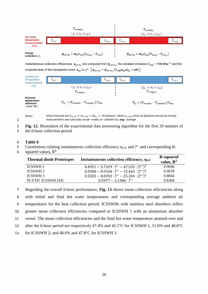
Fig. 12. Illustration of the experimental data processing algorithm for the first 20 minutes of 2 the 6-hour collection period 3
Table 6 4 Correlations relating instantaneous collection efficiency ηcol, and 𝑇∗ and corresponding R-5
squared values, R2 6
Thermal diode Prototypes Instantaneous collection efficiency, ηcol R-squared
value, 𝐑𝟐 ICSSWH 1 0.4951 − 5.7329 ∙ 𝑇∗ − 47.535 ∙ (𝑇∗)2 0.9046
ICSSWH 2 0.5908 − 8.9168 ∙ 𝑇∗ − 15.443 ∙ (𝑇∗)2 0.9078
ICSSWH 3 0.5583 − 8.0392 ∙ 𝑇∗ − 25.204 ∙ (𝑇∗)2 0.8844
PLVTD ICSSWH [43] 0.5977 − 3.1386 ∙ 𝑇∗ 0.8304
Regarding the overall 6-hour performance, Fig. 13 shows mean collection efficiencies along 7
with initial and final hot water temperatures and corresponding average ambient air 8
temperatures for the heat collection period. ICSSWHs with stainless steel absorbers reflect 9
greater mean collection efficiencies compared to ICSSWH 1 with an aluminium absorber 10
vessel. The mean collection efficiencies and the final hot water temperature attained over and 11
after the 6-hour period are respectively 47.4% and 42.1°C for ICSSWH 1, 51.6% and 48.8°C 12
for ICSSWH 2; and 48.0% and 47.8°C for ICSSWH 3. 13

27
1
Fig. 13. 6-hour mean collection efficiencies, related water and ambient air temperatures for the 2
thermal diode ICSSWH variants under constant simulated irradiance value of 730 ±10 Wm−2 3
4

28
Table 7 presents 12-hour and 18-hour summaries of experimental heat retention efficiency, 1
coefficient of thermal losses; associated average initial and final water temperatures in 2
storage vessel and the average ambient air temperature during the retention period for 3
prototypes ICSSWH 1 and ICSSWH 2. Consistent with results discussed under section 5.1, 4
prototype ICSSWH 2 which has a stainless steel absorber vessel presents better retention 5
performance compared to ICSSWH 1, which has an aluminium absorber. The ambient air 6
temperature varied between tests by as much as 3.5 °C during the cool down period, and by 7
±2.4 °C during the individual heat retention tests after the collection period. The main 8
observation is that the values of coefficient of thermal losses of prototypes investigated in the 9
current study are comparable to those of other partially evacuated thermal diode ICSSWHs in 10
literature [11,14,43]. 11

29
Table 7 1 12-hour and 18 hour heat storage/retention characteristics at night after a 6-hour collection 2 period under the solar simulator facility 3
System prototype ICSSWH 1 ICSSWH 2
Heat retention period (hours) 12 18 12 18
Retention Efficiency (%) 56.8 42.9 59.3 46.3
Thermal loss coefficient, U𝑠, (WK-1) 0.912 0.910 0.842 0.828
Initial water temperature (°C) 42.4 49.0
Final water temperature (°C) 31.7 27.8 36.9 32.7
Average ambient air temperature (°C) 17.5 16.8 19.2 18.7
6. Considerations on reported experimental results 4
The current article examines performance differences of three thermal diode ICSSWH 5
prototypes with respect to heat collection and retention. There are important considerations, 6
which may significantly influence the magnitude of the presented results but with no 7
significance on the conclusions drawn in the current study. The effect of wind speed and wind 8
direction on collection efficiency, coefficient of thermal losses and retention efficiencies 9
depends on the level of the vacuum created in the annular thermal diode and was not 10
investigated in the present study. Since the rate of thermal losses from the collector prototypes 11
is dependent on the difference between the average hot water temperature and the ambient air 12
temperature these parameters were the primary focus of this study. When the ambient air 13
temperature increases, so does the collection efficiency for a particular average collector 14
operating temperature. The collector efficiency curve depicted in 15

30
1
Fig. 11 includes this effect in the reduced temperature difference. The irradiance level is also 2
important in that the variation of collector efficiency relates to the temperature dependence of 3
the heat loss coefficient. Literature [11] shows that there may be minor differences in the 4
efficiency curve of a thermal diode ICSSWH for the annular vacuum pressure range 900 ± 50 5
mbar applied for prototypes in this study. 6
7. Conclusion and research prospects 7
Horizontally operating thermal diode Integrated Collector Storage Solar Water Heater 8
(ICSSWH) prototypes with differing material and structural characteristics were designed, 9
fabricated, tested and their performance evaluated under simulated conditions. Experimental 10
work employed two different procedures: (a) internal heating of water in the storage vessel 11
followed by cooling under stable ambient conditions and (b) prototype exposure to constant 12
simulated irradiance followed by a cooling period overnight. Prototypes with an outer 13
radiation-absorbing vessel of stainless steel achieved greater heat retention and thermal energy 14

31
collection efficiencies compared to the prototype with an outer aluminium absorber vessel. In 1
the first procedure, the retention efficiency of prototypes with stainless steel absorber was at 2
least 36% greater than for the prototype with an aluminium absorber. In the second procedure, 3
under typical operating conditions, the aluminium absorber prototype (ICSSWH 1) achieves 4
instantaneous collection efficiency of 28.0% whilst ICSSWH 2 and 3 with stainless steel 5
absorber achieve 30.9% and 29.4% respectively. In addition, retention efficiencies and 6
coefficients of thermal losses for prototypes with stainless steel absorbers were better than for 7
the prototype with an aluminium absorber. These results are important for the possible 8
realisation of efficient horizontally operating thermal diode ICSSWH that are capable of 9
broadening the solar thermal technology scope in market. They are also important in facilitating 10
future seminal efforts concerning further development of this technology. However, several 11
issues are outstanding including researching: 12
(a) the influence of annular vacuum pressure on the performance of non-concentrating 13
horizontally operating thermal diode ICSSWHs, 14
(b) the effect of focusing sun light to the bottom portion of the absorber vessel directly 15
interfacing the liquid PCM, 16
(c) the effect of distributing sunlight uniformly around the absorber vessel along with 17
accompanying insulation/heat retention strategies, 18
(d) the outcome of employing alternative test rigs that allow the investigation of different 19
incidence angles and alternative collector orientations, 20
(e) the performance behaviour under water draw-off conditions preferably by heat 21
extraction via an integrated heat exchanger, 22
(f) the aspect of a holistic ecological performance of thermal diode ICSSWH 23
configurations through a detailed life cycle assessment, 24
(g) the application of numerical methods to investigate physical phenomena of forward and 25
reverse operation of the thermal diode. Pugsley et al [43] provides an initial detailed 26
analysis of a Planar Liquid-Vapour Thermal Diode (PLVTD) ICSSWH collector, 27
(h) the development of computer simulation models that allow the techno-economic 28
evaluation of thermal diode ICSSWHs under different climatic conditions. 29
Acknowledgements 30
This study was supported via funding from Department for Education (DfE), UK by way of an 31
International Studentship. The work was undertaken in tandem with the SolaFin2Go project 32

32
funded by Engineering and Physical Sciences Research Council (EPSRC), UK and Innovate 1
UK . Further thanks go to Busitema University for providing a study leave. 2
Declarations of Interest: None 3
Nomenclature 4
𝑄ap thermal energy incident on collector aperture (J) 5
𝑄col collected thermal energy (J) 6
𝜂col instantaneous efficiency of solar thermal collection (%) 7
𝜂col,m mean efficiency of solar thermal collection (%) 8
𝜂ret efficiency of thermal energy retention/heat retention (%) 9
𝑈s coefficient of thermal losses (WK-1) 10
𝑇w average absolute water temperature(°C) 11
𝑇a average absolute ambient air temperature (°C) 12
𝑇w,i average initial tank fill water temperature at start of collection period (°C) 13
𝑇w,f average final hot water temperature at end of collection period (°C) 14
𝑇i,N initial water temperatures during the cooling period (°C) 15
𝑇f,N final water temperatures during the cooling period (°C) 16
𝑇a,N average ambient air temperature during the cooling period (°C) 17
𝑇∗ reduced temperature difference parameter (𝑇w − 𝑇a) 𝐼avg⁄ (K m2 W⁄ ) 18
mw mass of water (kg) 19
𝜌 density of water (kg m−3) 20
𝑉𝑇 volume of inner storage vessel (m3) 21
𝐼avg average solar radiation flux incident on collector aperture (Wm−2) 22
∆𝑡 the test interval during the collection period (s) 23
∆𝑡N the interval period during the night cooling or heat retention period (s) 24
𝐴ap the projected area of the transparent cover (m2) 25
𝐶p,w specific heat capacity of water (Jkg−1K−1) 26
𝜏 transmissivoty (-) 27
𝛼 absorptivity (-) 28
𝜀 emissivity (-) 29
𝜌𝑟 reflectivity (-) 30
33
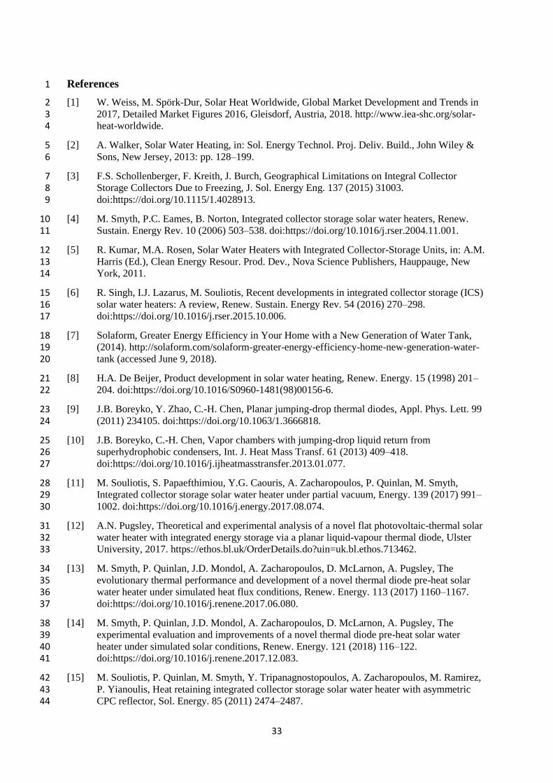
References 1
[1] W. Weiss, M. Spörk-Dur, Solar Heat Worldwide, Global Market Development and Trends in 2 2017, Detailed Market Figures 2016, Gleisdorf, Austria, 2018. http://www.iea-shc.org/solar-3 heat-worldwide. 4
[2] A. Walker, Solar Water Heating, in: Sol. Energy Technol. Proj. Deliv. Build., John Wiley & 5 Sons, New Jersey, 2013: pp. 128–199. 6
[3] F.S. Schollenberger, F. Kreith, J. Burch, Geographical Limitations on Integral Collector 7 Storage Collectors Due to Freezing, J. Sol. Energy Eng. 137 (2015) 31003. 8 doi:https://doi.org/10.1115/1.4028913. 9
[4] M. Smyth, P.C. Eames, B. Norton, Integrated collector storage solar water heaters, Renew. 10 Sustain. Energy Rev. 10 (2006) 503–538. doi:https://doi.org/10.1016/j.rser.2004.11.001. 11
[5] R. Kumar, M.A. Rosen, Solar Water Heaters with Integrated Collector-Storage Units, in: A.M. 12 Harris (Ed.), Clean Energy Resour. Prod. Dev., Nova Science Publishers, Hauppauge, New 13 York, 2011. 14
[6] R. Singh, I.J. Lazarus, M. Souliotis, Recent developments in integrated collector storage (ICS) 15 solar water heaters: A review, Renew. Sustain. Energy Rev. 54 (2016) 270–298. 16 doi:https://doi.org/10.1016/j.rser.2015.10.006. 17
[7] Solaform, Greater Energy Efficiency in Your Home with a New Generation of Water Tank, 18 (2014). http://solaform.com/solaform-greater-energy-efficiency-home-new-generation-water-19 tank (accessed June 9, 2018). 20
[8] H.A. De Beijer, Product development in solar water heating, Renew. Energy. 15 (1998) 201–21 204. doi:https://doi.org/10.1016/S0960-1481(98)00156-6. 22
[9] J.B. Boreyko, Y. Zhao, C.-H. Chen, Planar jumping-drop thermal diodes, Appl. Phys. Lett. 99 23 (2011) 234105. doi:https://doi.org/10.1063/1.3666818. 24
[10] J.B. Boreyko, C.-H. Chen, Vapor chambers with jumping-drop liquid return from 25 superhydrophobic condensers, Int. J. Heat Mass Transf. 61 (2013) 409–418. 26 doi:https://doi.org/10.1016/j.ijheatmasstransfer.2013.01.077. 27
[11] M. Souliotis, S. Papaefthimiou, Y.G. Caouris, A. Zacharopoulos, P. Quinlan, M. Smyth, 28 Integrated collector storage solar water heater under partial vacuum, Energy. 139 (2017) 991–29 1002. doi:https://doi.org/10.1016/j.energy.2017.08.074. 30
[12] A.N. Pugsley, Theoretical and experimental analysis of a novel flat photovoltaic-thermal solar 31 water heater with integrated energy storage via a planar liquid-vapour thermal diode, Ulster 32 University, 2017. https://ethos.bl.uk/OrderDetails.do?uin=uk.bl.ethos.713462. 33
[13] M. Smyth, P. Quinlan, J.D. Mondol, A. Zacharopoulos, D. McLarnon, A. Pugsley, The 34 evolutionary thermal performance and development of a novel thermal diode pre-heat solar 35 water heater under simulated heat flux conditions, Renew. Energy. 113 (2017) 1160–1167. 36 doi:https://doi.org/10.1016/j.renene.2017.06.080. 37
[14] M. Smyth, P. Quinlan, J.D. Mondol, A. Zacharopoulos, D. McLarnon, A. Pugsley, The 38 experimental evaluation and improvements of a novel thermal diode pre-heat solar water 39 heater under simulated solar conditions, Renew. Energy. 121 (2018) 116–122. 40 doi:https://doi.org/10.1016/j.renene.2017.12.083. 41
[15] M. Souliotis, P. Quinlan, M. Smyth, Y. Tripanagnostopoulos, A. Zacharopoulos, M. Ramirez, 42 P. Yianoulis, Heat retaining integrated collector storage solar water heater with asymmetric 43 CPC reflector, Sol. Energy. 85 (2011) 2474–2487. 44

34
doi:https://doi.org/10.1016/j.solener.2011.07.005. 1
[16] British Standards Institution, BS EN 12975-1:2006+A1:2010, Thermal solar systems and 2 components-solar collectors-Part 1: General requirements, 2010. 3
[17] Solar Rating & Certification Corporation. International Code Council - Solar Rating & 4 Certification Corporation (ICC-SRCC), Ratings Summary Page, (2018). https://secure.solar-5 rating.org/Certification/Ratings/RatingsSummaryPage.aspx?Type=1 (accessed September 22, 6 2018). 7
[18] R.D. Stewart, Detailed cost estimating, in: M. Kutz (Ed.), Mech. Eng. Handbook, Vol. 3 8 Manuf. Manag., John Wiley & Sons, New Jersey, 2006: pp. 531–563. 9
[19] U.R. Lenel, Materials and design of solar heating systems for domestic hot water, Mater. Des. 10 4 (1983) 701–705. doi:https://doi.org/10.1016/0261-3069(83)90132-2. 11
[20] D. Proctor, J.T. Czarnecki, The effect of aging on a 22-year-old solar water heater, Sol. 12 Energy. 35 (1985) 175–180. doi:https://doi.org/10.1016/0038-092X(85)90007-6. 13
[21] E. Van der Voet, L. Van Oers, M. Verboon, K. Kuipers, Environmental Implications of Future 14 Demand Scenarios for Metals: Methodology and Application to the Case of Seven Major 15 Metals, J. Ind. Ecol. (2018). doi:https://doi.org/10.1111/jiec.12722. 16
[22] K.J.J. Kuipers, L.F.C.M. van Oers, M. Verboon, E. van der Voet, Assessing environmental 17 implications associated with global copper demand and supply scenarios from 2010 to 2050, 18 Glob. Environ. Chang. 49 (2018) 106–115. 19 doi:https://doi.org/10.1016/j.gloenvcha.2018.02.008. 20
[23] M. Koehl, S. Saile, A. Piekarczyk, S. Fischer, Task 39 exhibition–assembly of polymeric 21 components for a new generation of solar thermal energy systems, Energy Procedia. 48 (2014) 22 130–136. doi:https://doi.org/10.1016/j.egypro.2014.02.016. 23
[24] A. Pugsley, A. Zacharopoulos, M. Smyth, J. Mondol, Performance evaluation of the senergy 24 polycarbonate and asphalt carbon nanotube solar water heating collectors for building 25 integration, Renew. Energy. (2017). doi:https://doi.org/10.1016/j.renene.2017.10.082. 26
[25] U.R. Lenel, P.R. Mudd, A review of materials for solar heating systems for domestic hot 27 water, Sol. Energy. 32 (1984) 109–120. doi:https://doi.org/10.1016/0038-092X(84)90054-9. 28
[26] F.M. Reinhart, J.F. Jenkins, Design for Corrosion Control of Potable Water Distribution 29 Systems, Naval Civil Engineering Lab, Port Hueneme, CA, 1975. 30 http://www.dtic.mil/dtic/tr/fulltext/u2/a006806.pdf. 31
[27] A.M. Shariah, A. Rousan, K.K. Rousan, A.A. Ahmad, Effect of thermal conductivity of 32 absorber plate on the performance of a solar water heater, Appl. Therm. Eng. 19 (1999) 733–33 741. doi:https://doi.org/10.1016/S1359-4311(98)00086-6. 34
[28] W.D. Callister Jr, D.G. Rethwisch, Fundamentals of materials science and engineering: an 35 integrated approach, 5th ed., John Wiley & Sons, Hoboken, NJ, 2016. 36
[29] F. Ardente, G. Beccali, M. Cellura, V. Lo Brano, Life cycle assessment of a solar thermal 37 collector, Renew. Energy. 30 (2005) 1031–1054. 38 doi:https://doi.org/10.1016/j.renene.2004.09.009. 39
[30] S.A. Kalogirou, Environmental benefits of domestic solar energy systems, Energy Convers. 40 Manag. 45 (2004) 3075–3092. doi:https://doi.org/10.1016/j.enconman.2003.12.019. 41
[31] F.J. Rey-Martínez, E. Velasco-Gómez, J. Martín-Gil, L.M. Navas Gracia, S. Hernández 42 Navarro, Life cycle analysis of a thermal solar installation at a rural house in Valladolid 43 (Spain), Environ. Eng. Sci. 25 (2008) 713–724. doi:https://doi.org/10.1089/ees.2007.0115. 44

35
[32] G.N. Tiwari, A.K. Tiwari, Handbook of solar energy: Theory, analysis and applications, 1 (2016). 2
[33] C. Garnier, Performance Measurement and Mathematical Modelling of Integrated Solar Water 3 Heaters, Edinburgh Napier University, 2009. 4
[34] M. Kutz, Mechanical Engineers’ Handbook, Volume 1: Materials and Engineering Mechanics, 5 4th ed., John Wiley & Sons, New Jersey, 2015. 6
[35] AECOM, Spon’s Mechanical and Electrical Services Price Book 2018, 49th ed., CRC Press, 7 Oxon, 2018. 8
[36] A. Zollner, S.A. Klein, W.A. Beckman, A performance prediction methodology for integral 9 collection-storage solar domestic hot water systems, J. Sol. Energy Eng. 107 (1985) 265–272. 10 doi:https://doi.org/10.1115/1.3267690. 11
[37] A. Zacharopoulos, J.D. Mondol, M. Smyth, T. Hyde, V. O’Brien, State-of-the-art solar 12 simulator with dimming control and flexible mounting, in: Proc. ISES Sol. World Congr. 2009 13 Renew. Energy Shap. Our Futur. 11-14 Oct., International Solar Energy Society, 14 Johannesburg, South Africa, 2009: p. 854. 15
[38] The US department of energy, Weather Data, EnergyPlus, (n.d.). 16 https://energyplus.net/weather (accessed January 2, 2019). 17
[39] W. Streicher, Solar Thermal Technologies for Domestic Hot Water Preparation and Space 18 Heating, Elsevier Ltd, 2016. doi:https://doi.org/10.1016/B978-1-78242-213-6.00002-3. 19
[40] W.B. Gillett, J.E. Moon, Solar collectors: Test methods and design guidelines, Series A, D. 20 Reidel Publlishing Company, Dordrecht, 1985. 21
[41] J.A. Duffie, W.A. Beckman, Solar engineering of thermal processes, 4th ed, John Wiley & 22 Sons, New Jersey, 2013. 23
[42] British Standards Institution, EN ISO 9806:2017, Solar energy. solar thermal collectors. Test 24 methods, 2018. 25
[43] A. Pugsley, M. Smyth, J. Mondol, A. Zacharopoulos, L. Mattia, Experimental characterisation 26 of a flat panel integrated collector-storage solar water heater featuring a photovoltaic absorber 27 and a planar liquid-vapour thermal diode, in: 11th ISES EuroSun Conf. 11-14 Oct. 2016, 28 Palma, Mallorca, Spain, International Solar Energy Society (ISES), Freiburg, Germany, 2017: 29 pp. 1294–1305. 30
31