Embed Size (px)
Citation preview

Research ArticleExperimental Investigation of Brazilian 14-X B HypersonicScramjet Aerospace Vehicle
João Felipe de Araujo Martos,1 Israel da Silveira Rêgo,2 Sergio Nicholas Pachon Laiton,1
Bruno Coelho Lima,1 Felipe Jean Costa,1 and Paulo Gilberto de Paula Toro2
1 Instituto Tecnologico de Aeronautica, Praca Marechal Eduardo Gomes, No. 50, Vila das Acacias,12.228-900 Sao Jose dos Campos, SP, Brazil2Instituto de Estudos Avancados, Trevo Coronel Aviador Jose Alberto Albano do Amarante, No. 1 Putim,12.228-001 Sao Jose dos Campos, SP, Brazil
Correspondence should be addressed to Joao Felipe de Araujo Martos; [email protected]
Received 7 February 2017; Accepted 30 March 2017; Published 2 May 2017
Academic Editor: Linda L. Vahala
Copyright © 2017 Joao Felipe de Araujo Martos et al. This is an open access article distributed under the Creative CommonsAttribution License, which permits unrestricted use, distribution, and reproduction in any medium, provided the original work isproperly cited.
The Brazilian hypersonic scramjet aerospace vehicle 14-X B is a technological demonstrator of a hypersonic airbreathing propulsionsystem based on the supersonic combustion (scramjet) to be tested in flight into the Earth’s atmosphere at an altitude of 30 kmand Mach number 7. The 14-X B has been designed at the Prof. Henry T. Nagamatsu Laboratory of Aerothermodynamics andHypersonics, Institute for Advanced Studies (IEAv), Brazil. The IEAv T3 Hypersonic Shock Tunnel is a ground-test facility able toproduce high Mach number and high enthalpy flows in the test section close to those encountered during the flight of the 14-X Binto the Earth’s atmosphere at hypersonic flight speeds. A 1m long stainless steel 14-X Bmodel was experimentally investigated at T3Hypersonic Shock Tunnel, for freestreamMach numbers ranging from 7 to 8. Static pressure measurements along the lower surfaceof the 14-X B, as well as high-speed Schlieren photographs taken from the 5.5∘ leading edge and the 14.5∘ deflection compressionramp, provided experimental data. Experimental data was compared to the analytical theoretical solutions and the computationalfluid dynamics (CFD) simulations, showing good qualitative agreement and in consequence demonstrating the importance of thesemethods in the project of the 14-X B hypersonic scramjet aerospace vehicle.
1. Introduction
A new era of hypersonic flight started, in August 1963, whenRobert M. White flew the rocket-powered North AmericanX-15, at 2020.6m/s, corresponding to a flight Mach numberof 6.7, at an altitude of 108 km [1]. Since then, a significantamount of research and development has been conductedworldwide into high-speed combustion and propulsion sys-tems [2].
In 2007, Prof. Henry T. Nagamatsu Laboratory ofAerothermodynamics and Hypersonics at the Institute forAdvanced Studies (IEAv), Brazil, began to research anddevelop a hypersonic waverider with airframe-integratedscramjet engine as an option to space access in the near future[3, 4], as shown in Figure 1.
Today, the Brazilian Air Force High Command hasconsidered the 14-X project as strategic to Brazil’s sovereign-ty.
Inspired by HyShot [5], X-43 [6–9], and X-51 [10] pro-grams that demonstrated the operation of scramjet engineswith planar configuration, new versions of the 14-Xwaveriderwere then designed to operate into the stratosphere atflight Mach number 7 such as the 14-X B [11, 12] (planarconfiguration of the 14-X waverider) and the 14-X S (mirror-image of the 14-X B with respect to its symmetry axis), asshown in Figure 2.
In whatever 14-X configuration, the Brazilian solid boost-ers S31 and S30 should assist them with lift-off from oneof the Brazilian Launch Centers to their operational flightconditions.
HindawiInternational Journal of Aerospace EngineeringVolume 2017, Article ID 5496527, 10 pageshttps://doi.org/10.1155/2017/5496527
2 International Journal of Aerospace Engineering
Figure 1: Artistic view of the 14-X scramjet-powered waverider.
(a) (b)
Figure 2: Conceptual design of the 14-X B scramjet-powered vehicle (a) and the 14-X S scramjet-powered propulsion stage (b).
Now, referring to scramjet inlets, it is well known that thenumber of ramps (blends) is directly related to system per-formance in terms of total pressure recovery and complexityin terms of machining and costs. The HyShot compressionsystem used only one ramp [5], while the X-51 [10] used threeramps to achieve the designated conditions for combustion.In this sense, the 14-X B inlet is quite unique because itconsists of two ramps only and a flat cowl, resulting in twooblique and one reflected shock wave in a way that theairflow speed and temperature expected at the entrance ofcombustion chamber are supersonic and above the flash pointof hydrogen for self-ignition, respectively.
Despite the optimistic tone above, this paper shows theshock tunnel investigations on the internal airflow char-acteristics of the 14-X B version operating at around analtitude of 30 km and freestream Mach number near to7. In addition, theoretical calculations and computationalfluid dynamics simulations of such an internal airflow arepresented.
2. Experimental Apparatus
2.1. Hypersonic Shock Tunnel Facility. The T3 0.60m nozzleexit diameter Reflected Hypersonic Shock Tunnel is a newHypersonic High Enthalpy Real Gas Pulsed Reflected ShockTunnel Facility (Figure 3) funded by Sao Paulo ResearchFoundation (FAPESP, process n∘ 2004/00525-7), which wasdesigned [13, 14] at the Prof. Henry T. Nagamatsu Laboratoryof Aerothermodynamics and Hypersonics primarily as a
DriverDDS
Driven
Nozzle
TestsectionDump
tank
Figure 3: T3 0.61m. nozzle exit diameter Hypersonic Shock Tunnelat IEAv.
research and development (R&D) facility for basic inves-tigations on supersonic combustion applied to high-speedadvanced airbreathing propulsion.
The simplest Reflected Hypersonic Shock Tunnel is ashock tube equipped with a convergent-divergent nozzleto produce high Mach number and high enthalpy flowsin the test section close to those encountered during theatmospheric flight of the 14-X B at hypervelocity. The basichypersonic shock tunnel consists of a high-pressure sec-tion (driver) and a low-pressure section (driven) separatedfrom each other by a double diaphragm system (DDS), aconvergent-divergent nozzle and its diaphragm (placed at the

International Journal of Aerospace Engineering 3
Lightsource
Opticalslit
Concavemirror
Flatmirror
High speedcamera
Nozzle
Test section
Collimatedbeam
Concavemirror
Flatmirror
Knifeedge
Figure 4: Schlieren visualization and high-speed camera system setup.
5.5∘
14.5∘
10.73∘
4.27∘
Figure 5: Cross section of the 14-X B hypersonic scramjet aerospace vehicle.
end of the driven section), and a test section terminated by alarge dump tank [15].
The T3 Hypersonic Shock Tunnel was designed [14] to beoperated in the 6–25 flight Mach number range, generatingreservoir enthalpies in excess of 10MJ/kg and reservoirpressures up to 25MPa when operated in the equilibrium-interface mode, with estimated useful test time up to 10ms.These conditions are estimated based on the driver-to-drivenarea ratio of 2.25, on the driven length equal to 100 timesthe driven internal diameter (127mm), and on the operatingdriver pressure of 5000 psi.
The T3Hypersonic Shock Tunnel is capable of generatingboth high and low enthalpy hypersonic flow conditions.In the present investigation for high enthalpy runs, heliumis used as the driver gas and the tunnel operates in theequilibrium-interface condition to produce a useful test timeof roughly 2ms. The test section airflow Mach number isabout 7 to 8, while pressure and temperature are similarto those encountered in 28 km, when in the high enthalpyoperation mode [16].
2.2. Instrumentation. A high-speed camera Phantom V411,coupled with a Schlieren optical system in “z” configuration(Figure 4), has been used for slow-motion visualization of thehypersonic flow. The Schlieren system is composed of a LEDas light source, an optical slit and focusing lens, two parabolicand three flat mirrors, and a knife edge.The Phantom camera
was set to acquire 43,329 frames per second (fps) with aresolution of 368× 200 pixels, recording during the entire testtime.
A multichannel oscillography is utilized to synchronizeboth data acquisition system and Schlieren system within theuseful shock tunnel test time. The scope unit was triggeredby a piezoelectric pressure transducer located immediatelyupstream of the nozzle entrance. Also, this pressure trans-ducer reads the reservoir pressure before expansion along thenozzle.
Two other pressure transducers, located 0.314m apartclose to the end of the driven section andmounted flush withthe inner wall of the shock tube end (heavy section), wereutilized to time the passage of the incident shock wave.
2.3. 14-X BTestModel Design. For experimental investigationin T3 Hypersonic Shock Tunnel, the 14-X B model wasscaled based on the 14-X S hypersonic scramjet aerospacevehicle design for flight at Mach number 7 and an alti-tude of 30 km. The 14-X B (Figure 5) consists of a two-dimensional configuration, with a constant cross section,where the upper flat surface, with zero angle of attack, isaligned with the freestream Mach number 7 hypersonicairflow.The double ramp scramjet inlet represents a forebodyexternal compression region followed by a small region ofinternal compression.This mixed compression configurationcan balance the problems of high external drag in the case

4 International Journal of Aerospace Engineering
Table 1: Thermodynamic properties of the airflow field along the 14-X B model lower surface, considering power-off case, inviscid flow, and𝛾 = 1.4 [11].
Quantity Unit Inlet entrance 1st ramp 2nd ramp Combustor entrance Internal expansion surface External expansion surface𝑀in 7.00 7.00 6.02 4.06 2.60 2.79𝜃in ∘ 5.50 14.50 20.00 4.27 10.73𝛽out ∘ 12.24 22.11 32.24𝑀out 6.02 4.06 2.60 2.79 3.37𝑇out K 226.50 296.75 568.46 1,039.72 953.45 747.17𝑝out Pa 1,197.00 2,877.57 16,755.80 89,105.97 65,803.41 2,8052.13𝜌out kg/m3 0.0184 0.0338 0.1027 0.2986 0.2405 0.1308𝑎out m/s 301.70 345.98 478.87 647.63 620.17 549.05𝑢out m/s 2,111.90 2,082.41 1,946.38 1,684.62 1,735.30 1,851.13
(a)
Mach number
0.00
7.10
5.32
3.55
1.77
(b)
Figure 6: Domain and mesh used on CFD simulation (a) and Mach distribution for flight at Mach 7 (b).
of full external compression and excessive viscous effectsduring full internal compression. The optimal cowl inletconfiguration is the well-known “shock-on-lip” conditionshown in Figure 5 [17].
The lower surface consists of a frontal surface with aleading edge angle of 5.5∘, a compression ramp with an angleof 14.5∘ (related to the angle of the leading edge), an expansioncombustion chamber with an angle of 4.27∘, and an externalexpansion surface with an angle of 10.73∘ (related to the angleof the inner expansion).
The combustor chamber has constant area and is longenough to optimize the combustion, followed by a slope of4.27∘ (to accommodate the boundary layer and expansiondue to H
2and O
2combustion). The combustion chamber
constant area (and its height) is proportional to the airflowcaptured by the 14-X B frontal area to preserve the mass flow.
The 14-X B model lower surface was designed basedon the two-dimensional compressible flow (oblique shockwave relationships) and expansion wave (Prandtl-Meyertheory), considering the simplest case, that is, no viscousflow, calorically perfect air (𝛾 = 1.4), and scramjet enginewith power off [11]. Also, the following restrictions wereassumed: The incident shock waves generated at the 5.5∘leading edge and at the 14.5∘ compression ramp hit the cowlleading edge (shock-on-lip condition). The reflected shockwave generated at the cowl leading edge hits the entrance of
the combustor station (shock-on-corner condition) as shownin Figure 5. Table 1 lists the airflow properties along the14-X B model, considering the simplifications as mentionedabove.
3. CFD Analysis
In order to solve the systemof governing equations for a high-speed compressible problem, the ANSYS Fluent disposes thedensity-based solver. In the density-basedmethod, the veloc-ity and density fields are obtained from the continuity andmomentum equations, and the pressure field is obtained fromthe equation of state. ANSYS Fluent solves simultaneouslyall the integral governing equations (continuity, momentum,and energy) simultaneously. Then, additional scalars such asequations for turbulence models are solved and separatedfrom one another.
Figure 6 shows the computational domain of the 14-XB studied here. The freestream conditions considered in thefollowing simulations are the experimental ones (describedbelow). The wall thermal conditions studied were 300Kuniform temperature due to the short test time available onhypersonic shock tunnel. In addition, the transitional viscousmodel used was the Transition SST (Fluent Code) with idealgas that according to a previous analysis is the most suitableoption for this case considering the results obtained and
International Journal of Aerospace Engineering 5
(a) (b)
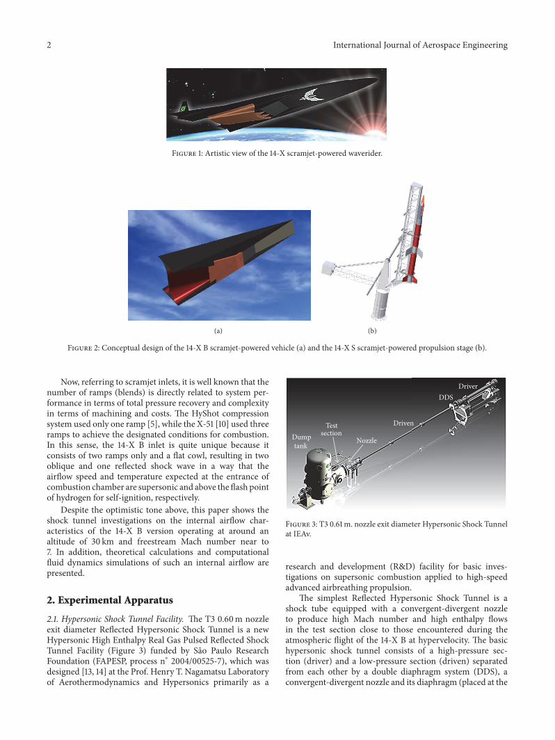
Figure 7: 14-X B model installed in the T3 test section: (a) Laboratory model and (b) setup of the combustion chamber entrance for flowvisualization across the quartz windows.
1,25ms 1,5ms
1,75ms 2,0ms
Figure 8: Temporal evolution of the chocked flow for ideal gas simulation.
computational power available [18]. The model used is basedon the combination of the SST k-𝜔 transport equations withtwo other transport equations: intermittency and one for thetransition onset criteria, in terms of momentum-thicknessReynolds number. The intermittency set was 1 as default byfluent, with turbulent intensity of 5% and turbulent viscosityratio of 10.
Meshes used had around 5𝐸 + 5 cells being more refinednear the walls in order to better calculate the physicalinteractions in the boundary layer and at the regions nearthe corner and leading edges. The mesh configuration wasunstructured composed of Triangular elements. Figure 6(b)shows the mesh for the entire domain as well as Machdistribution obtained at this simulation.
4. Experimental Results
4.1. Flowfield Visualization over the 14-X B Inlet. A 1m longstainless steel 14-X B model (Figure 7(a)) instrumented withtwenty-nine piezoelectric pressure transducers on its lowersurface was experimentally investigated in the T3HypersonicShock Tunnel running at freestreamMach numbers from 7 to
8 and in the equilibrium-interface mode operation. The 14-XB model was installed on the heavy steel stands, especiallydesigned to hold firmly the model in the T3 test section.Since the two symmetrical quartz windows utilized for theSchlieren visualization technique have their limitations asnonvariable position and useful area of visualization, the14-X B model was positioned to optimize the visualizationarea for the second ramp and combustion chamber inlet(Figure 7(b)).
Fourteen runs were made, six of them using air in thedriver section for perfect gas simulation and eight of themusing helium in the driver section for real gas simulation.Before these, a few runs were made to identify and correctsome project errors and ensure that the acquisition systemwas fully operational. Some problems were faced: The modelhad a 0.5∘ angle of attack; blending deformation of the leadingedge has occurred due to its thin thickness; and the height ofcombustion chamber was not enough to accommodate theviscous effects resulting in chocked flow (Figure 8).
Some modifications were made to solve these problemsfound such as changing the cowl position, correcting the cowltip position and the combustor height to prevent the chocked
6 International Journal of Aerospace Engineering
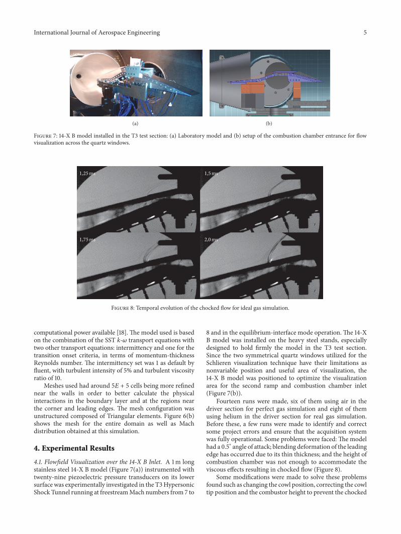
(a)
Separationshock wave
Separatedshear layer
Recompressionshock wave
Separationpoint
Separatedflow
Reattachmentpoint
Neckregion
(b)
Figure 9: Boundary layer shock wave interaction on the 14-X B inlet (a) and flow separation scheme (b).
flow in order to ensure the shock-on-lip condition instead ofthe shock-on-corner condition. In the first runs (Figure 9),an interaction between the boundary layer and the shockwave between the first and second compression ramps wasobserved, which caused the separation of boundary layer.
According to Heiser and Pratt [19], for Mach 7 andturbulent flow, themaximum turning angle should be around13∘ to avoid the boundary layer separation, while for Mach7 and laminar flow the maximum turning angle should bearound 5∘. The separation of the boundary layer is criticalfor a hypersonic inlet operation because it induces changesin shock wave angle and in pressure recovery as well asincrements in heat transfer while it may lead to chocked flow,resulting in flow spillage and even in unstart of the engine[20]. The 14-X B model has a turning angle of 14.5∘ betweenits compression ramps, such that for some experimentalconditions it was possible to observe this separation.
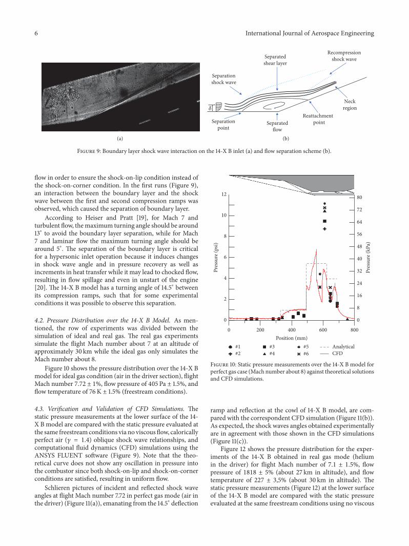
4.2. Pressure Distribution over the 14-X B Model. As men-tioned, the row of experiments was divided between thesimulation of ideal and real gas. The real gas experimentssimulate the flight Mach number about 7 at an altitude ofapproximately 30 km while the ideal gas only simulates theMach number about 8.
Figure 10 shows the pressure distribution over the 14-X Bmodel for ideal gas condition (air in the driver section), flightMach number 7.72 ± 1%, flow pressure of 405 Pa ± 1.5%, andflow temperature of 76K ± 1.5% (freestream conditions).
4.3. Verification and Validation of CFD Simulations. Thestatic pressure measurements at the lower surface of the 14-X B model are compared with the static pressure evaluated atthe same freestreamconditions via no viscous flow, caloricallyperfect air (𝛾 = 1.4) oblique shock wave relationships, andcomputational fluid dynamics (CFD) simulations using theANSYS FLUENT software (Figure 9). Note that the theo-retical curve does not show any oscillation in pressure intothe combustor since both shock-on-lip and shock-on-cornerconditions are satisfied, resulting in uniform flow.
Schlieren pictures of incident and reflected shock waveangles at flight Mach number 7.72 in perfect gas mode (air inthe driver) (Figure 11(a)), emanating from the 14.5∘ deflection
0
8
16
24
32
40
48
56
64
72
80
Pres
sure
(kPa
)
0
2
4
6
8
10
12
Pres
sure
(psi)
200 400 600 8000Position (mm)
AnalyticalCFD
#1#2
#3#4
#5#6
Figure 10: Static pressure measurements over the 14-X B model forperfect gas case (Mach number about 8) against theoretical solutionsand CFD simulations.
ramp and reflection at the cowl of 14-X B model, are com-pared with the correspondent CFD simulation (Figure 11(b)).As expected, the shock waves angles obtained experimentallyare in agreement with those shown in the CFD simulations(Figure 11(c)).
Figure 12 shows the pressure distribution for the exper-iments of the 14-X B obtained in real gas mode (heliumin the driver) for flight Mach number of 7.1 ± 1.5%, flowpressure of 1818 ± 5% (about 27 km in altitude), and flowtemperature of 227 ± 3,5% (about 30 km in altitude). Thestatic pressure measurements (Figure 12) at the lower surfaceof the 14-X B model are compared with the static pressureevaluated at the same freestream conditions using no viscous

International Journal of Aerospace Engineering 7
(a) (b)
(c)
Figure 11: Schlieren picture of the airflow field at flight Mach number 7.725 for perfect gas mode (a); CFD simulations at same conditions;(b) comparison between Schlieren picture and density contour (c).
Table 2: Thermodynamic properties of the airflow field along the 14-X B model lower surface considering the freestream properties for realgas simulation, power-off case, inviscid flow, and 𝛾 = 1.4.
Quantity Unit Inlet entrance 1st ramp 2nd ramp Combustor entrance Internal expansion surface External expansion surface𝑀in 7.10 7.10 6.18 4.14 2.68 2.88𝜃in ∘ 5.00 14.5 19.5 4.27 10.73𝛽out ∘ 11.088 21.377 30.793𝑀out 6.183 4.140 2.676 2,879 3.473𝑇out K 227,00 290,92 568.23 1,034.30 946.49 737.18𝑝out Pa 1,818.00 4,103.93 24,797.37 130,604.94 95,742.29 39,921.56𝜌out kg/m3 0.0279 0.0492 0.1521 0.4400 0.3525 0.1887𝑎out m/s 302.01 341.90 477.82 644.66 616.68 544.24𝑢out m/s 2,144.25 2,114.10 1,977.95 1,725.10 1,775.49 1,890.20
flow, calorically perfect air (𝛾 = 1.4) oblique shock waverelationships (Table 2), and computational fluid dynamicssimulations using the ANSYS FLUENT software. Again, CFDsimulations agree better with the experimental data whencompared to analytical theoretical calculations. As expected,the pressure distributions for real gas and ideal gas simulationare similar, once the Mach numbers and the structures ofshock waves are similar too.
It was considered air as calorically perfect (𝛾 = 1.4)because the maximum temperature, along of the lowersurface, of the 14-X Bmodel at design conditions is below thedissociation temperature (Tables 1 and 2).
Schlieren pictures of the incident and reflected shockwave angles for the flight Mach number 7.1 in real gasmode (helium in the driver) are shown in Figure 13(a). Theairflow field over the 14.5∘ deflection ramp and around the

8 International Journal of Aerospace Engineering
0
35
70
105
140
175
210
245
Pres
sure
(kPa
)
0
5
10
15
20
25
30
35
40
Pres
sure
(psi)
200 400 600 8000Position (mm)
AnalyticalCFD
#7#8
#9#10
#13#14
#11#12
Figure 12: Static pressure measurement over the 14-X B model in real gas mode.
(a) (b)
(c)
Figure 13: Schlieren picture of the airflow field for at flight Mach number 7.1 in real gas mode (a); CFD simulations at the same conditions;(b) comparison between Schlieren picture and density contour (c).
International Journal of Aerospace Engineering 9
of 14-X B cowl is compared with that correspondent toCFD simulations of the density variation (Figure 13(b)). Asexpected, the shockwaves angles obtained experimentally arein good accordance with the CFD simulation (Figure 13(c)).
The results obtained are qualitatively satisfactory despitesome quantitatively difference between the experimental dataand the results obtained theoretically and via CFD. Once theairflow field over the 14-X B model is in good accordancewith the CFD simulation, the pressure distribution should bein good accordance too, due to the hypersonic flow naturewhose properties before and after a shock wave are related toits intensity. Improvements in the data acquisition system andsensors are necessary to reduce errors and better understandthe gas dynamic phenomena involved during scramjet opera-tion.The evaluation of pressure and temperature distributionat the boundary layer also are necessary because of sensorpositioning.
5. Conclusion
An experimental investigation of the airframe-integratedscramjet 14-X B was made in the pulsed hypersonic windtunnel T3 at IEAv. Static pressure measurements along withhigh-speed Schlieren photographswere utilized to investigatethe hypersonic airflow field along the 14-X B model. Pressuremeasurements along the model were done and comparedwith the values calculated analytically via shock wave the-ory and computationally via CFD. Despite the quantitativedifferences, in general, the experimental and theoreticalvalues exhibit qualitatively the same behavior, but the CFDsimulations approximate better to the experimental data.High-speed Schlieren photographs compared with the CFDsimulations show that the architecture of the shock wavesgenerated over the 14-X B model is consistent with thatexpected for the shock-on-lip condition at flight Mach num-ber about 7 (project condition). Therefore, these results havedemonstrated the importance of matching theory, groundexperiments, and computational simulations in the project ofthe 14-X B hypersonic vehicle before flight tests.
Conflicts of Interest
There are no conflicts of interest.
Acknowledgments
The last author would like to express gratitude to FINEP(Agreement no. 01.08.0365.00) not only for the financialsupport for the 14-X hypersonic aerospace vehicle design andexperimental investigations but also for financial support tograduate students (period 2014-2015). Also, thanks are dueto the COMAER for financial support for graduate students(period 2016).
References
[1] J. J. Bertin and R. M. Cummings, “Fifty years of hypersonics:where we’ve been, where we’re going,” Progress in AerospaceSciences, vol. 39, no. 6-7, pp. 511–536, 2003.
[2] R. N. Kostoff and R. M. Cummings, “Highly cited literature ofhigh-speed compressible flow research,” Aerospace Science andTechnology, vol. 26, no. 1, pp. 216–234, 2013.
[3] P. G. P. Toro,M. A. S. Minucci, T. C. Rolim et al., “Brazilian 14-Xhypersonic aerospace vehicle project,” in Proceedings of the 18thAIAA/3AF International Space Planes and Hypersonic Systemsand Technologies Conference, Tours, France, 2012.
[4] M. F. F. Ricco, P. P. Funari, and A. V. Carvalho, Espaco,Tecnologia, Ambiente e Sociedade 1, Habilis Editora Erechim, vol.8, Habilis Press Editora, RS, Brazil, 2011.
[5] A. Paull, H. Alesi, and S. Anderson, “The development of theHyShot flight program,” in Proceedings of the 24th InternationalSymposium on Shock Waves, Beijing, China, 2005.
[6] C. R. Mcclinton, D. S. Rausch, and P. Reukauf, “Hyper-Xprogram status,” in Proceedings of 10th International SpacePlanes and Hypersonic Systems and Technologies, Kyoto, Japan,2001.
[7] P. L. Moses, V. L. Rausch, L. T. Nguyen, and J. R. Hill, “NASAhypersonic flight demonstrators—overview, status, and futureplans,” Acta Astronautica, vol. 55, no. 3–9, pp. 619–630, 2004.
[8] L. A. Marshall, G. P. Corpening, and R. Sherrill, “A chiefengineer’s view of the NASA X-43A scramjet flight test,” inProceedings of 3rd International Space Planes and HypersonicSystems and Technologies Conference, Capua, Italia, 2005.
[9] L. A. Marshall, C. Bahm, G. P. Corpening, and R. Sherrill,“Overview with results and lessons learned of the X-43A mach10 flight,” in Proceedings of AIAA/CIRA 13th International SpacePlanes and Hypersonic Systems and Technologies Conferenc,AIAA 2005-3336, 2005.
[10] J. M. Hank, J. S. Murphy, and R. C. Mutzman, “The X-51Ascramjet engine flight demonstration program,” in Proceedingsof 15th AIAA International Space Planes and Hypersonic Systemsand Technologies Conference, AIAA 2008-2540, Dayton, Ohio,USA, 2008.
[11] V. A. B. Galvao and P. G. P. Toro, “Brazilian 14-X B hypersonicscramjet aerospace vehicle analytical theoretical analysis atmach number 7,” in Proceedings of 22nd International Congressof Mechanical Engineering, Ribeirao Preto, Brazil, 2013.
[12] J. R. T. Silva and P. G. P. Toro, “Brazilian 14-X B hyper-sonic scramjet aerospace vehicle aerothermodynamic code,”in Proceedings of 22nd International Congress of MechanicalEngineering, Ribeirao Preto, Brazil, 2011.
[13] P. G. P. Toro, M. A. S. Minucci, J. B. Chanes Jr., A. L. Pereira,and H. T. Nagamatsu, “Development of a new hypersonicshock tunnel facility to investigate electromagnetic energyaddition for flow control and basic supersonic combustion,”in Proceedings of the 4th International Symposium on BeamedEnergy Propulsion, pp. 469–480, Nara, Japan, November 2005.
[14] P. G. P. Toro,M. A. S.Minucci, J. B. Chanes Jr. et al., “New hyper-sonic shock tunnel at the laboratory of aerothermodynamicsand hypersonics Prof. Henry T. Nagamatsu,” in Proceedingsof 4th International Symposium on Beamed Energy Propulsion,Kailua-Kona, Hawaii, USA, 2007.
[15] D. Romanelli Pinto, T. V. C. Marcos, V. A. B. Galvao et al.,“Flow characterization of the T3 hypersonic shock tunnel,” inProceedings of 28th International Symposium on Shock Waves,2011.
[16] J. A. Anderson Jr., Modern Compressible Flow, The HistoricalPerspective, McGraw-Hill, The Historical Perspective McGraw-Hill, Inc., 2nd edition, 1990.
[17] K. Subbarao and J. D. Goss, “Combinedmagnetohydrodynamicand geometric optimization of a hypersonic inlet,” International

10 International Journal of Aerospace Engineering
Journal of Aerospace Engineering, vol. 2009, Article ID 793647,pp. 1–12, 2009.
[18] A. F. Moura, A computational stufy of the airflow in scramjetintakes [Dissertation of Master in Sciences In Space and Tech-nology], Instituto Tecnologico de Aeronautica, Sao Jose dosCampos, Brazil, 2014.
[19] W. H. Heiser and D. T. Pratt, Institute of Aeronautics and Astro-nautics, American Institute of Aeronautics and Astronautics,Washington, Wash, USA, 1994.
[20] J. J. Bertin,Hypersonic Aerothermodynamics, American Instituteof Aeronautics and Astronautics, Washington, DC, USA, 1994.

RoboticsJournal of
Hindawi Publishing Corporationhttp://www.hindawi.com Volume 2014
Hindawi Publishing Corporationhttp://www.hindawi.com Volume 2014
Active and Passive Electronic Components
Control Scienceand Engineering
Journal of
Hindawi Publishing Corporationhttp://www.hindawi.com Volume 2014
International Journal of
RotatingMachinery
Hindawi Publishing Corporationhttp://www.hindawi.com Volume 2014
Hindawi Publishing Corporation http://www.hindawi.com
Journal of
Volume 201
Submit your manuscripts athttps://www.hindawi.com
VLSI Design
Hindawi Publishing Corporationhttp://www.hindawi.com Volume 201
Hindawi Publishing Corporationhttp://www.hindawi.com Volume 2014
Shock and Vibration
Hindawi Publishing Corporationhttp://www.hindawi.com Volume 2014
Civil EngineeringAdvances in
Acoustics and VibrationAdvances in
Hindawi Publishing Corporationhttp://www.hindawi.com Volume 2014
Hindawi Publishing Corporationhttp://www.hindawi.com Volume 2014
Electrical and Computer Engineering
Journal of
Advances inOptoElectronics
Hindawi Publishing Corporation http://www.hindawi.com
Volume 2014
The Scientific World JournalHindawi Publishing Corporation http://www.hindawi.com Volume 2014
SensorsJournal of
Hindawi Publishing Corporationhttp://www.hindawi.com Volume 2014
Modelling & Simulation in EngineeringHindawi Publishing Corporation http://www.hindawi.com Volume 2014
Hindawi Publishing Corporationhttp://www.hindawi.com Volume 2014
Chemical EngineeringInternational Journal of Antennas and
Propagation
International Journal of
Hindawi Publishing Corporationhttp://www.hindawi.com Volume 2014
Hindawi Publishing Corporationhttp://www.hindawi.com Volume 2014
Navigation and Observation
International Journal of
Hindawi Publishing Corporationhttp://www.hindawi.com Volume 2014
DistributedSensor Networks
International Journal of