Embed Size (px)
Citation preview

HAL Id: hal-02350134https://hal.archives-ouvertes.fr/hal-02350134
Submitted on 5 Nov 2019
HAL is a multi-disciplinary open accessarchive for the deposit and dissemination of sci-entific research documents, whether they are pub-lished or not. The documents may come fromteaching and research institutions in France orabroad, or from public or private research centers.
L’archive ouverte pluridisciplinaire HAL, estdestinée au dépôt et à la diffusion de documentsscientifiques de niveau recherche, publiés ou non,émanant des établissements d’enseignement et derecherche français ou étrangers, des laboratoirespublics ou privés.
Experimental investigation and performance analysis ofArchimedes screw generator
Guilhem Dellinger, Abdelali Terfous, Pierre-Andre Garambois, AbdallahGhenaim
To cite this version:Guilhem Dellinger, Abdelali Terfous, Pierre-Andre Garambois, Abdallah Ghenaim. Experimentalinvestigation and performance analysis of Archimedes screw generator. Journal of Hydraulic Research,Taylor & Francis, 2016, 54 (2), pp.197-209. �10.1080/00221686.2015.1136706�. �hal-02350134�

September 12, 2015 Journal of Hydraulic Research Main˙JHR˙V3
To appear in the Journal of Hydraulic ResearchVol. 00, No. 00, Month 20XX, 1–19
Research Paper
Experimental investigation and performance analysis of Archimedes ScrewGenerator
GUILHEM DELLINGER, PhD Student, Laboratoire des sciences de l’ingenieur, de l’informatique et de
l’imagerie (ICUBE), Institut National des Sciences Appliquees (INSA) de Strasbourg, Strasbourg, France
Email: [email protected] (author for correspondence)
ABDELALI TERFOUS (IAHR Member), Associate Professor, Laboratoire des sciences de l’ingenieur, de
l’informatique et de l’imagerie (ICUBE), Institut National des Sciences Appliquees (INSA) de Strasbourg,
Strasbourg, France
Email: [email protected]
PIERRE-ANDRE GARAMBOIS, Assistant Professor, Laboratoire des sciences de l’ingenieur, de
l’informatique et de l’imagerie (ICUBE), Institut National des Sciences Appliquees (INSA) de Strasbourg,
Strasbourg, France
Email: [email protected]
ABDELLAH GHENAIM, Professor, Laboratoire des sciences de l’ingenieur, de l’informatique et de
l’imagerie (ICUBE), Institut National des Sciences Appliquees (INSA) de Strasbourg, France
Email: [email protected]
ABSTRACTGeneration of renewable energy with Archimedes Screw Generators (ASG) transforming potential energy of a fluidflow into mechanical energy is a growing technology convenient for low-head hydraulic sites. This paper presents animproved theoretical model linking screw performances to screw geometry and flow conditions. This model takes intoaccount leakages, friction losses and variable fill levels. The modeled values of torques and efficiencies are in fairlygood agreement with experimental results obtained for a laboratory-scale screw. The downstream screw immersion isshown to impact ASG efficiency and an optimal level is determined. It is also found that fluid friction on screw is notnegligible and a friction coefficient is calibrated experimentally. Interestingly, it is found that a single value is suitablefor modeling performances under various flow conditions. Leakage phenomenon in under filling flow conditions andfriction forces in complex turbulent flows could be further studied.
Keywords: Archimedes screw generator; Experimental facilities; Hydraulic models; Hydraulics of renewableenergy systems; Laboratory studies
1 Introduction
Finding new, safe, renewable energy is becoming more and more of a priority with global warm-ing. One solution that is gaining popularity is the micro central hydraulics. Today, the micro-hydroelectricity has a large unexploited potential in Europe thanks to thousands of unused oldmills or weirs. Among the many types of turbines, the Archimedes Screw Generator (ASG) is adeveloping way enabling the exploitation of these hydro sites. Known for more than 2000 years,the operating principle of the Archimedean screw was used as a pumping system to raise largeamounts of water for low head sites. It is still used today for pumping wastewater in treatmentplants. Its use as turbine for energy production was introduced for the first time by Radlik (1997).
v1.0 released April 2015

September 12, 2015 Journal of Hydraulic Research Main˙JHR˙V3
The first ASG was installed in 1997 on the Eger river in Aufhausen (Germany) and produces 4kW. There are now more than 180 hydropower plants of this type across Europe and more than400 worldwide (Lashofer, Hawle, & Pelikan, 2012), the most powerful ASG is in the Albert Canal(Belgium) and generates 400 kW. This technology is still in its infancy and is a growing field.
According to the study by Williamson, Stark, and Booker (2014), the hydrodynamic screw has ahigh potential at low head and low flow sites. The maximum head and flow are respectively about10 m and 10 m3s−1. Among the main advantages of the ASG, high efficiencies can be maintaineddespite fluctuations of inflow discharge. According to Brada (1999), the flow rate can vary about±20% around the nominal flow without impacting efficiency. A recent study on 70 ASGs in Europeshows that the average in situ efficiency is about 69% with a maximum of 75% (Lashofer et al.,2012). An important point is its robustness; sediments and small debris can pass through an ASGwithout damaging it. The ASG is also usually assumed as fish friendly. Indeed, studies done onthe river Dart have shown that with bumpers fitted on the leading edges, almost all kinds of fishcan pass through the ASG without injuries (Kiebel, 2007, 2008; Kiebel & Coe, 2011). However,the effects of ASGs on fish are still under discussion and in particular for small screw systems withhigh rotational speeds.
For design and optimization purposes, experimental and theoretical studies tried to link the ASGefficiency to its geometrical parameters and flow features. The experimental research conductedby Brada (1999) have shown the impact of speed and inflow water levels on ASG efficiency; how-ever the downstream water level is not accounted despite its importance as shown in the presentstudy. Lashofer, Hawle, and Pelikan (2013) tested experimentally the ASG performances for a largerange of screw geometries. The impact of different geometrical parameters on screw efficiency wasobserved and it was concluded that the ASG design can still be improved. Laboratory tests werealso performed on ASG with rotatory trough in order to eliminate leakage. Lower performanceswere found compared to an ASG with fixed trough, suggesting this diminution of performances isdue to the friction between fluid and trough. About maximal ASG efficiencies in laboratory, Brada(1999) found results close to 80%; Lubitz, Lyons, and Simmons (2014) and Lashofer et al. (2013)had results ranging between 80% and 90%, whereas field efficiencies are on the order of 75% onaverage. This could be attributable to the fact that rotation speeds are generally not optimal fora given discharge. Moreover, river discharge is fluctuating in time, requiring and adaptive ASGspeed to optimize performances.
Regarding geometry optimization, Rorres (2000) determined numerically the screw geometrymaximizing the amount of water turbined in one turn of screw. Although these works have beendone for Archimidean screw used as pump, these results are commonly used for ASG designing.Nuernbergk and Rorres (2012) developed an analytical model based on semi-empirical equationsfor the water inflow. It helps determine optimal values for inflow conditions given a screw geometry.This model can be useful to determine possible implantation sites. Assuming that the screw turnsbecause of the water pressure (supposed hydrostatic) on the blades, Muller and Senior (2009)proposed a simplified theoretical model. The leakages are taken into account using the empiricalequation given by Nagel and Radlik (1988). This equation was determined for an Archimedeanscrew used as a pump and operating in full condition. Their study shows that the screw efficiencyis independent of the rotational speed. However, their model simplifies the screw geometry and doesnot take into account various other losses. Consequently, it is hard to use it for predicting a realisticASG efficiency. Nuernbergk (2012) derived a model that takes into account leakage losses and thefriction losses due to the viscosity of the fluid. The author considered a real screw geometry andan accurate leakage model that is not only based on empirical results. However, the variations ofthe water fill level in the screw are not taken into account. Hence, it is hard to determine the screwperformances for different flow rates at fixed rotational speed or vice-versa. Recently Lubitz et al.(2014) proposed a model that takes into account the water fill level and the real screw geometrybut friction losses are not included. Thus, by comparing their numerical and experimental results,the authors found a theoretical efficiency much higher than the experimental efficiency. Among the
2

September 12, 2015 Journal of Hydraulic Research Main˙JHR˙V3
few references dealing with ASG, lots of questions remain especially for design purposes. There isstill no comprehensive theoretical model on the Archimedean screw used as turbine. Today, theASG designing is hence mainly based on empirical results.
This paper presents an improved theoretical model that takes into account the influence of leakageas proposed by Nuernbergk (2012), variable fill levels as highlighted by Lubitz et al. (2014), but alsofriction losses. In what follows, the hypothesis and calculations leading to the model are detailled.Then, experimental values measured on a laboratoratory scale screw are used for validating theefficiencies and torques determined with our model. Moreover, experimentations provide insightsinto the influence of various hydraulic and geometric parameters on the ASG performances. Finally,the fairly good capacities of the new model proposed for predicting the ASG performances and foroptimizing its design are discussed.
The paper is structured as follows. The operating principle and notations are introduced in section2. In section 3, the theoretical model is established for variable fill levels. The experimental devicethat allows modification of flow conditions and geometrical parameters is presented in section 4.Results and discussions are exposed in section 5.
2 Definition and operating principle
An ASG consists in a screw rotating in an open and fix trough. The potential energy of the fluidflowing through the plant is transformed in mechanical energy thanks to the rotation of the screw.This mechanical energy is then transformed into electricity using a generator. The power providedby the ASG is given by
PASG = ρ g QH ηASG (1)
where PASG is the power, ρ is the density of water, Q is the flowrate, g is the acceleration of gravity,H is the geodetic head and ηASG is the efficiency of the whole system. The ASG efficiency is directlylinked to thegenerator efficiency and to the different losses present in the plant. These main headlosses, which result in power losses, are due to the leakages and frictional forces induced by thefluid viscosity. Minimizing these losses is thus important in order to obtain optimal efficiency.
The main features of an ASG are the head H, the total flowrate flowing through the plant Q, therotational speed of the screw n and the ASG efficiency ηASG. The geometrical parameters of thescrew shown in Fig. 1 are the outer radius Ra, the inner radius Ri, the pitch of the screw S, thetotal length L, the threaded length Lb, the number of blades N and the screw inclination β. LikeRorres (2000), we define the volume of water trapped between two successive blades. This volumeis named ”bucket” and is equal to VB. In the following analysis, all buckets present in a screw areassumed to be similar. Then, we define the optimal filling point of the screw which is reached whenthe filling level in a bucket is at the limit of overflowing in the next lower bucket. Figure 2 showsa screw at the optimal filling point with the different buckets.
By neglecting the various flow leakages, the flowrate flowing through the ASG is equal to thevolume of water evacuated in one turn of screw multiplied by its rotational speed. Hence, we definethe nominal flow Qnom by
Qnom = N VBn
60(2)
where n is the rotational speed of the screw. The nominal rotational speed nnom is thus equal to
nnom =Qnom 60
N VB(3)
3

September 12, 2015 Journal of Hydraulic Research Main˙JHR˙V3
Figure 1 Geometrical parameters of the screwFigure 2 Archimedean screw at optimal filling point with
the different buckets
3 Theoretical model
In order to design an ASG, it is important to be able to predict the axial torque provided by thescrew and its efficiency - function of the flow features and geometrical parameters. As stated above,the model is established to explain how the different equations are extended to variable fill levels.The first part in the development of the theoretical model deals with the computation of the torqueand the second one with the calculation of the different losses.
3.1 Axial torque computation
The axial torque delivered by the screw is due to the pressure, supposed hydrostatic, exerted bythe water on each blade of the screw. A hydrostatic pressure is exerted on one blade by its upperand lower bucket. The pressure due to the upper bucket will lead to a motor torque on the screwaxis. Conversely, the pressure due to the lower bucket will create a braking torque. Both torquesare added to obtain the resulting torque delivered by one blade adjacent to two successive bucketswithin the screw.
We define the system (O,x,y,z) represented in Fig. 3. The lines (1), (2) and (3) represent re-spectively the water level for a screw in underfilling, at the optimal filling point and in overfilling.Knowing that the blades of the screw are helicoidal, for all point M belonging to a blade surfacewith the change of variable ϕ = 2π z/S, we have
xM
= rM
cos(ϕM
)y
M= r
Msin(ϕ
M)
zM
=S
2πϕ
M
where r ∈ [Ri, Ra]. Now, let us define the elementary force df due to the hydrostatic pressureon a elementary surface dA. An example of this elementary surface dA for a given point M isrepresented in Fig. 3. We know that the direction of this force is orthogonal to the blade surface.Hence, df = Pstat dA where Pstat is the hydrostatic pressure that is function of the water columnabove the elementary surface dA. We use dA = dbdr where db is the elementary curvilinear lengthand dr is the elementary radial length. For a parametric curve we have
db =
√(dx
dϕ
)2
+
(dy
dϕ
)2
+
(dz
dϕ
)2
(4)
4

September 12, 2015 Journal of Hydraulic Research Main˙JHR˙V3
(1)
(2)
(3)
βe
β
he
Mx
y
z
Figure 3 Archimedean screw profile in the system (O,x,y,z)
Hence
dA = dr dϕ r
√1 +
(S
2π r
)2
(5)
The hydrostatic pressure Pstat for any point M on the wetted surface of the blade is equal to
Pstat(M) = ρ g H(M) = ρ g (yM− h(z
M)) (6)
where H(M) is the height of the water column above the point M and h(zM
) is the water levelwhich is function of the screw filling. The elementary torque dC due to the force df at M is equalto
dC = df r sin(βe) (7)
where βe = cotan(S/2π r) is the angle between the blade and the screw axis. This angle is rep-resented in Fig. 3. The total torque is obtained by integrating the equation (7) on the upper andlower wetted surfaces of a blade. Finally, the torque delivered by one blade is equal to
Cth,blade =
∫∫surf,sup
ρ g (yM− h(z
M)) r sin
(cotan(
S
2π r)
)dA
−∫∫
surf,infρ g (y
M− h(z
M)) r sin
(cotan(
S
2π r)
)dA
(8)
The torque provided by all the threaded length of the screw is
Cth,screw = Cth,bladeLbN
S(9)
5

September 12, 2015 Journal of Hydraulic Research Main˙JHR˙V3
It may be noted that the theoretical power output of the screw could be determined by
Pth,screw = Cth,screw ω (10)
where ω is the rotational speed of the screw.
3.2 Efficiency computation
Losses identification and efficiency
Screw efficiency is directly linked to the different power losses that are non linear functions withrespect to flow parameters. The different losses in an ASG have a direct influence on the screwefficiency and the efficiency is a non linear function of inflow discharge. As exposed by Nuernbergkand Rorres (2012), the power losses are due to leakage between the trough and the blades Pl, toleakage by over-filling Pover, to the friction between the water and the blades Pblade, to the frictionbetween the water and the trough Ptrough and to the friction between the water and the screw corePcore. These losses are calculated by Nuernbergk (2012) for an ASG operating at an optimal fillingpoint. Thus, if the flow rate varies, the rotational speed of the screw will change consequently asdescribed by equation (3) and conversely. The ASG efficiency is thus given by
η = 1−∑Plosses
Phydraulic= 1−
Pl + Pover + Pblade + Ptrough + Pcoreρ g QH
(11)
The total flowrate Q is the sum of the nominal flow defined in equation (3) plus all the leakageflows. Then, we have
Q = Qnom +Ql +Qover (12)
where Ql is the leakage between the trough and the blades and Qover is the leakage by over-filling.We propose here to use the main method of losses calculation and to extend it to variable screw
filling. It will then be possible to determine the evolution of efficiency for a fixed flow rate andvariable rotational speeds; and vice et versa.
Leakage between trough and blades
To determine the leakage gap, Muysken (1932) assumed that the leakage flow between two suc-cessive blades is similar to emptying a hydraulic tank. The author deduced the flow velocity, andknowing the gap between the blades and the trough, the leakage flowrate was calculated. Thisleakage is eventually determined by the following equation
Ql = µl sspRa
(1 +
ssp2Ra
) √1 +
(S
2πRa
)2 (2
3α1 + α2 +
2
3α3
) √2gδh (13)
where Ql is the leakage flowrate and ssp is the gap between the blades and the trough. The constantµl is the contraction coefficient of discharge ranging between 0.65 and 1. Here µl = 1 is chosen, i.e.for maximum gap leakage. The term δh = S sin(β)/N is the height difference between the waterlevel of two successive buckets. The angles α1, α2 and α3 are drawn in Fig. 4 and are numericallydetermined. The angles α1 and α3 correspond to the blade area that is only under the pressure ofan upper bucket. The pressures of an upper and lower bucket are exerted on an area corresponding
6

September 12, 2015 Journal of Hydraulic Research Main˙JHR˙V3
y
x
α3
α2
α1
Figure 4 Representation of the angles necessary for the leakagecomputation
to α2. The power loss due to leakage between the trough and the blades is equal to
Pl = ρ g QlH (14)
Leakage due to over-filling
The leakage due to the flow over the screw core appears when the flow rate is too high or therotational speed too low. In this case, a triangular spillway is formed. Nuernbergk and Rorres(2012) suggest using the over-filling leakage model given by Aigner (2008) to estimate the flow rate
Qover =4
15µover
√2g
(1
tanβ+ tanβ
)h5/2e (15)
The weir coefficient µover shall be taken as µ = 0.537 (for maximum spillway leakage). The termhe corresponds to the height of the triangular spillway (Fig. 3). The power loss due to over-fillingis then given by
Pover = ρ g QoverH (16)
Friction of water on trough
Friction force on trough is due to the viscous fluid motion through the ASG system. This force isproviding work, then energy is dissipated. It is given by
Ftrough = τtroughAtrough =λtrough
8ρ c2
axAtrough (17)
where τtrough is the shear stress of fluid on trough and Atrough is the wetted area of the trough,thelatter being numerically determined. Assuming that we have a free-surface flow in a smooth channel,the shear stress is described with the friction law of Darcy-Weisbach where λtrough is the frictioncoefficient of water on the trough, ρ is the fluid density and cax is the average axial flow velocity
7

September 12, 2015 Journal of Hydraulic Research Main˙JHR˙V3
in the trough. Assuming that this velocity is equal to the axial velocity of the blades, we have
cax =S n
60(18)
Assuming that we have a semi-circular free-surface flow, the friction coefficient λtrough can bedetermined using the Manning equation for the axial velocity. The details of the calculations areexposed in Nuernbergk (2012) and are used without modifications. After determining λtrough andcalculating Atrough, it is possible to compute Ftrough. The work of the friction forces along thetrough is then equal to
Wtrough = Ftrough LB
= ρ Vwater g htrough(19)
where Vwater is the total volume of water and htrough is the head due to the friction. Then we have
htrough =Ftrough LBρ Vwater g
(20)
Finally, the power loss due to the friction on the trough is equal to
Ptrough = ρ g Qhtrough (21)
Friction of water on screw core
The friction of the fluid on the screw core generates a friction force due to fluid viscosity and thencreates a resistant torque. This force is determined by
Fcore = τcoreAcore (22)
where τcore is the shear stress of fluid on screw core and Acore is the wetted area of the screw corewhich is numerically determined. Again, for a free surface flow on a smooth surface, the friction isdescribed with the Darcy-Weisbach’s law and a constant friction coefficient. Then the shear stressτcore is defined by
τcore =λscrew
8ρ c2
f/core (23)
where λscrew is the friction coefficient of the fluid on the screw and cf/core is the assumed fluidvelocity relative to the core. This coefficient λscrew is experimentally determined. The fluid velocitycf/core relative to the screw core is equal to ur where ur = 2π Ri n/60 is the radial component ofthe velocity. The brake torque due to this friction is then equal to
Ccore = FcoreRi (24)
Finally, the power loss due to the friction of the fluid on the screw core is given by
Pcore = Ccore ω (25)
where ω = 2π n/60 is the rotational speed of the screw.
8

September 12, 2015 Journal of Hydraulic Research Main˙JHR˙V3
Friction of water on blades surface
As previously, fluid flow on the upper and lower wetted surfaces of blades generates a friction forcedue to fluid viscosity and then creates a brake torque. The elementary friction force is equal to
dFblade = τblade dA (26)
where τblade is the shear stress of fluid on blades and dA = dbdr is the elementary surface. TheDarcy-Weisbach’s law is used again to describe the friction. Then, the shear stress τblade is givenby
τblade =λscrew
8ρ c2
f/blade (27)
where cf/blade is the assumed fluid velocity relative to a blade and λscrew is the same friction coef-ficient than previously used for the friction on screw core. The elementary brake torque projectedon the screw axis is equal to
dCf,blade = dFblade r cos(βe) =λscrew
8ρ
(2π n
60
)2
r3 cos(βe) dbdr (28)
The total brake torque is then equal to
Cf,blade =λR8ρ
(2π n
60
)2 [∫∫p,sup
cos(βe) r3dbdr +
∫∫p,inf
cos(βe) r3dbdr
](29)
The bounds of the integrals correspond to to the upper and lower wetted surface of a blade. Theintegrals are numerically approximated. The brake torque for all the screw length is equal to
Cf,screw =LB N
SCf,blade (30)
Finally, the power loss due to fluid friction on the blades is determined by
Pblade = Cf,screw ω (31)
4 Experimental device
In order to investigate experimentally the ASG performances, an experimental device with alaboratory-scale Archimedean screw was elaborated. It is installed in the fluid mechanics labo-ratory at the INSA of Strasbourg. This device enables testing of the screw for different geometricalparameters and flow conditions. The experimental results will be compared to the theoretical onesobtained from the model exposed above. The flowrate, the inclination of the screw, the rotationalspeed and the downstream water level can be changed with the experimental device (Fig. 5). Allgeometrical parameters and flow conditions are represented in Table 1.
The experimental device is installed in a 0.75 m width and 5 m length open channel. The inlet andoutlet have circular cross-sections of 0.15 m diameter. The Archimedean screw is manufactured inABS with a 3D printer. The turbine is supported by two sealed ball bearings. The screw is directlycoupled to the axis of a RE050G Maxon (48V , 418W ) DC motor with steel bellows coupling. Therotational speed of the screw can be controlled by using the motor as a brake. Moreover, it is alsoused as a measurement device. Indeed, the rotational speed of the screw is proportional to the
9

September 12, 2015 Journal of Hydraulic Research Main˙JHR˙V3
Table 1 Geometrical parameters and flow conditions
Outer radius of the screw - Ra (m) 0.096Inner radius of the screw - Ri (m) 0.052
Geometrical parameters Pitch of the screw - S (m) 0.192Threaded length of the screw - LB (m) 0.4Number of blades - N 3Inclination of the screw - β (◦) 18 ... 30Gap width between screw and trough - ssp (m) 0.0007
Rotational speed of the screw - n (min−1) 60 ... 180Flow conditions Flow rate - Q (m3s−1) 0.001 ... 0.004
Water level downstream - hout (m) 0 ... 0.25Water level upstream - hin (m) 0.26 ... 0.35
voltage and torque to electrical current. Then we have the torque delivered by the motor definedby Cmotor = ktorque I and the rotational speed by n = kspeed U where ktorque is the torque constant,I is the electric current at the motor terminals, kspeed is the constant of speed and U is the voltageat the motor terminals. It is important to note that ktorque and kspeed are independent of the motorefficiency in our range of rotational speed. In order to determine the value of the gap between troughand blades ssp, we measured this gap with slip gauges at both ends of the screw for different radialpositions. The maximal gap corresponding to ssp = 0.0007 is used. Water is supplied at the inletof the experimental device with a centrifugal pump (Fig. 5). The fluid flows through the screwand leads to its rotation thanks to the pressure exerted on its blades. Finally, the water escapes atthe outlet located downstream of the adjustable weir (Fig. 5). The downstream level is controlledwith an adjustable weir. The flowrate is measured with a PROMAG 30F Endress Hauser magneticflowmeter with a given measuring accuracy of ±0.5 %. The downstream and upstream water levelsare measured with dial gauges. For each operating point, corresponding to one flow condition andone rotational speed, 1500 instantaneous values of rotational speed and torque are recorded in 15s. These measures give an average rotational speed and torque. Subsequently, these average valuesare used for analyzing the performances of the screw. The measures are recorded and analyzedwith the software Labview 2013 through a National Instrument data acquisition device (NI USB6008).
The power produced by the screw is determined by
Pscrew = Cscrew ω (32)
where Pscrew is the power provided by the screw and Cscrew is the torque provided by the screw.The torque provided by the screw is equal to
Cscrew = Cmotor + Cfriction (33)
where Cmotor is the brake torque delivered by the motor and Cfriction is the torque induced by thefriction in the bearings. In order to know the real screw torque, the friction torque Cfriction wasestimated by measuring the motor torque necessary for rotating the screw for different rotationalspeeds. It appears that this torque increases linearly with the speed and a linear regression gives
Cfriction(n) = 0.000171n+ 0.046065 (34)
As we use preloaded bearings, we expect that the equation 34 does not change significantly with ascrew partially or completely filled. The turbine efficiency is then equal to
η =Pscrew
Phydraulic=Cscrew ω
ρ g QH(35)
10

September 12, 2015 Journal of Hydraulic Research Main˙JHR˙V3
Adjustable weir
Outlet
hout
h1
β
hin
Inlet
DC Motor
Figure 5 Experimental device
where Phydraulic is the hydraulic power provided by the moving fluid.
5 Results and Discussion
5.1 Impact of downstream level on ASG performances
According to Lyons and Lubitz (2013), the downstream water level has a direct impact on ASGperformances. In the present study, experimental measurements are performed in order to determineoptimal operating points for various downstream water levels and screw inclinations. These resultscould be useful for ASG design and site selection in real river networks. The screw performancesare tested for different outlet levels hout and inclinations at fixed speed and flow rate. Downstreamwater level is controlled with an adjustable weir (Fig. 5).
To compare the results, we define the screw immersion that corresponds to the following ratio
I =hout − h1
2Ra cos(β)(36)
where h1 is represented in Fig. 5. Thus, for I = 0, the water level is at the low end of the screw .Conversely, for I = 1, the end of the screw is completely immersed. Different levels of immersionare represented in Fig. 6. According to Nuernbergk (2012), the optimal downstream level hout,optiis obtained from
hout,opti = (Ra +Ri)
√1−
(tan(β)S
2π Ri
)2
cos(β)− S
Nsin(β) + h1 (37)
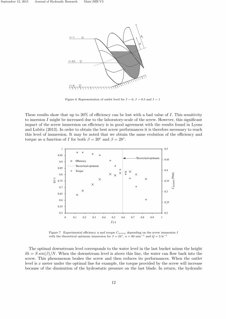
The rotational speed is fixed at n = 80 min−1 and the flowrate at Q = 3 ls−1 for all these tests.Figure 7 shows the experimental efficiency and the torque depending on the immersion I for a
screw inclination of 24◦. It also shows the theoretical optimal immersion Iopt obtained from theequations (36) and (37). Note that the torque provided by the screw decreases when I is decreasing.This can be explained by the fact that downstream water exerts pressure on the last blade of thescrew. Thus, this pressure that brakes the screw increases when the water level is increasing andthen, reduces the torque. It can be observed on Fig. 7 that given (β, n,Q) the efficiency increaseswith I before reaching a maximum for I around 0.64. Once this value is reached, the efficiencydecreases while the immersion continues to increase. Thus, there is only one optimal value of I.
11
September 12, 2015 Journal of Hydraulic Research Main˙JHR˙V3
I = 1
I = 0.5
I = 0
Ri
Ra
Figure 6 Representation of outlet level for I = 0, I = 0.5 and I = 1
These results show that up to 20% of efficiency can be lost with a bad value of I. This sensitivityto imersion I might be increased due to the laboratory-scale of the screw. However, this significantimpact of the screw immersion on efficiency is in good agreement with the results found in Lyonsand Lubitz (2013). In order to obtain the best screw performances it is therefore necessary to reachthis level of immersion. It may be noted that we obtain the same evolution of the efficiency andtorque as a function of I for both β = 20◦ and β = 28◦.
0.2
0.25
0.3
0.35
0.4
0.45
0.5
0.5
0.55
0.6
0.65
0.7
0.75
0.8
0.85
0.9
0.95
1
0 0.1 0.2 0.3 0.4 0.5 0.6 0.7 0.8 0.9 1
η (
-)
Efficiencyf
Theoreticalfoptimum
Torquef
Theoreticalfoptimum
I (-)
Cscrew
(Nm
)
Figure 7 Experimental efficiency η and torque Cscrew depending on the screw immersion I
with the theoretical optimum immersion for β = 24◦, n = 80 min−1 and Q = 3 ls−1
The optimal downstream level corresponds to the water level in the last bucket minus the heightδh = S sin(β)/N . When the downstream level is above this line, the water can flow back into thescrew. This phenomenon brakes the screw and then reduces its performances. When the outletlevel is x meter under the optimal line for example, the torque provided by the screw will increasebecause of the diminution of the hydrostatic pressure on the last blade. In return, the hydraulic
12

September 12, 2015 Journal of Hydraulic Research Main˙JHR˙V3
power delivered by the flow will increase of ρ g Qx. Unfortunately, the gain in hydraulic power issuperior to the gain in mechanical power and as we have η = Pscrew/Phydraulic, the efficiency willeventually decrease.
Table 2 Theoretical and experimental optimums
of screw immersion for β = 20◦, β = 24◦ andβ = 28◦
Optimal immersion - Iopt
Inclination (◦) Theoretical Experimental20 0.632 0.6724 0.596 0.6428 0.536 0.57
Table 2 exposes the theoretical and experimental optimums of immersion for different screwinclinations - figures not presented. Remark that experimental values are slightly higher thanthe theoretical values but show the same trend: both theoretical and experimental values of Ioptdecrease when the screw inclination increases. This evolution can be explained by the geometry.Finally, the equation (37) gives a good estimation of the optimal downstream water level. We alsonoticed that the downstream water level impacts directly the screw sound emission. Indeed it wasnoted qualitatively that the sound emission is louder for lower immersion levels. In the next part,all the experimental results are obtained with a screw operating at optimal immersion.
5.2 Comparison to theoretical model
In order to evaluate the theoretical model described in the previous part, theoretical results arecompared to experimental measurements. Two measurement sets of screw efficiency and axialtorque are performed. A firstset is done with variable flowrates and fixed rotational speed while asecond set is done with constant flowrate and variable rotational speeds. For each set, the screwis tested for three different inclinations. Geometrical parameters and flow conditions for theseexperiments are exposed in Table 3.
Table 3 Flow conditions and geometrical parameters for experiments at variable rotational speed and
variable flow rate
Variable speed Variable flow rate
Inclination (◦) Q (ls−1) I nnom (min−1) n (min−1) I Qnom (ls−1)20 3 0.64 84.2 90 0.60...0.65 3.224 3 0.60 90.6 90 0.57...0.61 2.9828 3 0.54 98.7 90 0.5...0.55 2.73
The results obtained with the theoretical model are highly dependent on the total head H. Know-ing the weir height and the flow rate, it is possible to determine the evolution of the downstreamwater level. But it gets more difficult to determine the upstream water level. Although Nuernbergkand Rorres (2012) developed a model to predict water inflow of an Archimedean screw, the resultsobtained with this model do not corroborate our measurements. It is probably due to the size ofthe laboratory-scale screw. To avoid this difficulty, the experimental values of H are used in ourefficiency model.
To obtain the theoretical torque Cth, the brake torques due to friction are subtracted from thetorque Cth,screw. So, we have
Cth = Cth,screw − Cf,screw − Ccore (38)
The torques Cth,screw, Ccore and Cf,screw derive respectively from the equations 9, 24 and 30. The
13

September 12, 2015 Journal of Hydraulic Research Main˙JHR˙V3
value of the coefficient λscrew is adjusted until the theoretical and experimental efficiencies match.The same value of λscrew, approximatively 0.084, is found for variable flowrates or rotationalspeeds, and for each inclination. Nuernbergk (2012) found a value of this coefficient equal to 0.035based on the experimental results of Brada (1999). The fact that our friction coefficient is muchhigher can be explained by the larger roughness of our screw. The theoretical values of efficiencyand axial torque presented below derived respectively from the equations 11 and 38.
0
0.1
0.2
0.3
0.4
0.5
0.6
0.7
0.8
0
0.1
0.2
0.3
0.4
0.5
0.6
0.7
0.8
0.9
1
0.7 0.8 0.9 1 1.1 1.2 1.3 1.4 1.5 1.6
n/nnom d-g
Experimentalcefficiency
Theoreticalcefficiency
Experimentalctorque
Theoreticalctorque
β =c24°Q =c3cls-1
Under-fillingOver-filling
Optimalcfillingcpoint
η d
-g
Csc
re
wdN
mg
Figure 8 Experimental and theoretical (from equations 11 and 38) values for efficiency and
axial torque depending on n/nnom with β = 24◦ and Q = 3 ls−1
Figure 8 exposes the evolution of the screw efficiency and axial torque depending on n/nnom forβ = 24◦ and Q = 3 ls−1. We can see that with the increase of the rotational speed, the experimentalefficiency increases until reaching a maximum value. For higher values of rotational speed theefficiency decreases. There is only one optimal speed which corresponds here to n/nnom = 0, 95.The maximum efficiency is slightly above 80%, this is in good agreement with the laboratoryresults found in the literature (80% in Lubitz et al. (2014), 80% in Brada (1999) and 90% inLashofer et al. (2013)). We note that the best efficiency is obtained for a slight over-filling foreach screw inclination. The performance degradation with low speed is mainly due to over-fillingwhich leads to leakage over the screw core. Conversely, when the speed is too high, the screw isunder-filled. Gap leakage and friction forces will be predominant. Figure 8 shows that the torquedecreases for increasing rotational speed. It is due to the screw filling that decreases when nincreases at constant flowrate. The pressure on the blades, as well as the torque, is then decreasing.Moreover, when the rotational speed increases, the friction forces that brake the screw increasetoo. For low speed, we notice a good agreement between theoretical and experimental values ofefficiency and torque. It is particularly interesting to see that the theoretical model gives the sameoptimal value of n/nnom. It shows the importance of taking into account the friction losses in themodel and it can partially explain why Lubitz et al. (2014) obtained theoretical efficiencies muchgreater than the experimental ones. It should be noted that the theoretical torque is slightly higherthan measurements with the friction coefficient λscrew defined previously. This difference can beexplained by the fact that the term LbN/S in the equation (9) may lead to an overestimation ofthe torque Cscrew. When the ratio n/nnom exceeds 1.3, we can see that the experimental efficiencydecreases. The same phenomenon occurs for β = 20◦ and β = 28◦ for the same value of n/nnom
14

September 12, 2015 Journal of Hydraulic Research Main˙JHR˙V3
and therefore for the same filling point. We assume that gap leakage is underestimated above thispoint. Indeed, leakage tests were performed for the screw standing at the optimal and at 60%filling points. We found good agreement between theoretical and experimental leakage which arecomparable when the screw is totally filled. However for low filling, we obtained respectively atheoretical and experimental leakage decrease of about 25% and 15%. At low filling, the theoreticalmodel hence predicts less leakage than in reality. This may explain as well the experimental torquediminution compared to the theory at high rotational speed.
Figure 9 shows the different ratios of power loss to hydraulic power depending on n/nnom. Wecan see first that the friction losses increase quickly with the rotational speed, especially for thefriction on blades that exceeds 30 % for high rotational speed. The gap leakage decreases slowlywhen the speed increases but is still close to 5 %. When the screw is over-filled, we see that theover-filling leakage increases quickly to reach 10 % and becomes the most important source of lossfor n/nnom = 0.7. At optimal filling point, the two most important losses are the friction of wateron the blades surface and gap leakage. Thus, the screw efficiency is strongly depending on thefriction forces and not only on gap leakage. However, the friction forces are very important herebecause of the roughness of the screw.
0
0.05
0.1
0.15
0.2
0.25
0.3
0.35
0.4
0.7 0.8 0.9 1 1.1 1.2 1.3 1.4 1.5 1.6
P/Phyd
(-)
n/nnom( -)
Leakage trough - blades Leakage over-fillingTotal hydraulic lossesFriction in bearings
β = 24°Q= 3 ls-1 Friction of water on the blades surface
Friction of water on the screw core
Friction of water on the trough
Figure 9 Evolution of different theoretical losses plus experimental bearings losses depending
on n/nnom with β = 24◦ and Q = 3 ls−1
Figure 10 exposes the evolution of the screw efficiency and axial torque depending on Q/Qnomfor β = 24◦ and n = 90 min−1. As previously, we can see that there is only one optimal flowratethat gives the highest efficiency. This optimal corresponds to Q/Qnom = 1.08. We obtain the samevalue for β = 20◦ and β = 28◦. Moreover, for each inclination we obtain the highest efficiencywhen the screw is slightly over-filled. As before, the efficiency decreases when the screw is in over-filling situation because of the leakage over the screw core. In under-filling situation, we note thatthe efficiency is only very slightly affected until Q/Qnom = 0.8. Below this value, the efficiencydecreases quickly for each screw inclination. Thus, efficiency is affected only above a given fillingpoint. We assume that this is due to the leakage between trough and blades which becomes moreimportant from this point. Thus, there is only a small decrease in ASG efficiency for a ±20%variation of discharge around the optimal value. This is in good agreement with the experimentalresults of Brada (1993) and Lashofer et al. (2013). For ASG with variable speed, good efficienciescan be maintained over a wider range of operating conditions. However, according to Lashofer et al.
15

September 12, 2015 Journal of Hydraulic Research Main˙JHR˙V3
(2012), this kind of ASG is much more expensive and such a device is only relevant with significantriver flow fluctuations. As can be expected, the torque decreases when the flow rate is decreasing.
0
0.1
0.2
0.3
0.4
0.5
0.6
0.7
0
0.1
0.2
0.3
0.4
0.5
0.6
0.7
0.8
0.9
1
0.5 0.6 0.7 0.8 0.9 1 1.1 1.2
Q/Qnom g-O
Experimentalyefficiency
Theoreticalyefficiency
Experimentalytorque
Theoreticalytorque
β =y24°n =y90ymin-1
Under-filling Over-filling
Optimalyfillingypoint
η g
-O
Csc
rew
gNm
O
Figure 10 Experimental and theoretical (from equations 11 and 38) values for efficiency andaxial torque depending on Q/Qnom with β = 24◦ and n = 90 min−1
It can be explained, as previously, by the diminution of pressure on the blades when the screwfilling is decreasing. Once again we see that there is a good agreement between experimental andtheoretical values of efficiency and torque. Moreover, theory and experiments give the same optimalvalue of Q/Qnom. But below Q/Qnom = 0.8, the experimental values decrease more quickly thantheoretical ones. The axial torque values obtained by the theoretical model are slightly smaller thanthose measured experimentally, with the friction coefficient defined previously. This difference ismore pronounced for low flow values. As previously, we think that the differences in efficiency andtorque for low flow values stem from the underestimation of the gap leakage.
Figure 11 gives the different ratios of power loss to hydraulic power depending on Q/Qnom. Wesee that the two most significant losses are the friction on blades and the gap leakage loss and thattheir maximum value is respectively of 15% and 7%. Both are decreasing slowly when the flowrate increases. As expected, the loss due to over-filling leakage increases quickly as soon as we areabove the optimal filling point. Once again, these results demonstrate the importance of takinginto account the friction forces. To obtain better performances, the value of λscrew and ssp mustbe minimized.
6 Conclusion
Allthough Archimedian screw used as turbine demonstrate a good potential for hydropower gen-eration, low-head sites are still under-exploited and guidelines are still missing for an improveddesign of ASGs. This paper presents an improved theoretical model that predicts the performancesof an Archimedean screw generator. It is based on the analysis and modelling of several physicalphenomena. The first part of the model computes the axial torque provided by the screw fromthe pressure exerted by the fluid on the blades. The second part gives the screw efficiency fromempirical equations for variable filling points. Subsequently, our theory is confronted to experi-mental measurements thanks to a laboratory-scale Archimedean screw. This device enables the
16

September 12, 2015 Journal of Hydraulic Research Main˙JHR˙V3
0
0.05
0.1
0.15
0.2
0.25
0.3
0.35
0.4
0.6 0.7 0.8 0.9 1 1.1 1.2
P/Phyd
(-)
Q/Qnom( -)
Leakage trough - bladesLeakage over-fillingTotal hydraulic lossesFriction in bearings
β = 24°n = 90 min-1
Friction of water on the screw coreFriction of water on the blades surfaceFriction of water on the trough
Figure 11 Evolution of different theoretical losses plus experimental bearings losses depend-
ing on Q/Qnom with β = 24◦ and n = 90 min−1
investigation of the hydraulic performances of an ASG.Experiments show the critical influence of downstream water level on the screw performances.
Moreover the existence of an optimal point of screw immersion depending on the inclination ishighlighted. By comparing with theoretical outlet level given by Nuernbergk (2012), we find ex-perimental values slightly higher for each inclination.
To evaluate the theoretical model, two campaigns of measurements have been done with, in eachcase, three different screw inclinations. The first campaign was performed at a constant flowrate anda variable rotational speed and, the second one, at a fixed rotational speed and a variable flowrate.In each case a good agreement between experimental and theoretical values of efficiency and torqueis found above a certain point of filling. Thus, for low filling, experimental values of torque andefficiency decrease quicker than the theoretical values. We assume that this phenomenon is dueto underestimation of leakage gap at low filling. This study highlighted the importance of takinginto account the friction forces in an ASG. Thus, in order to optimize the screw performances, itis essential to minimize the gap between the blades and trough but also to minimize the value ofthe friction coefficient between the screw and the fluid.
Finally, the theoretical model presented can be used to predict the ASG performances andespecially to determine optimal flow rate or rotational speed. To be effective at low screw filling,the model of gap leakage will be improved. More experiments will be done for new screw geometriesand friction coefficients. In addition, the model used will be confronted to a real-scale Archimedeanscrew.
Acknowledgements
The authors gratefully aknowledge all the partners involved in the project MCH funded by FUI(Fonds Unique Interministriel). We also want to thank the three reviewers that helped to signifi-cantly improve the paper.
17

September 12, 2015 Journal of Hydraulic Research Main˙JHR˙V3
Notation
Ablade = wetted area of one blade (m2)Acore = wetted area of the screw core (m2)Atrough = wetted area of the trough (m2)cax = average axial flow velocity in the trough (ms−1)Ccore = resistant torque due to friction of fluid on screw core (Nm)Cfriction = resistant torque due to friction in bearings (Nm)Cf,screw = resistant torque due to friction of fluid on blades (Nm)Cmotor = resistant torque provided by the motor (Nm)Cth = theoretical torque provided by the screw minus the resistant torques
due to friction between fluid and the screw (Nm)Cscrew = experimental torque provided by the screw (Nm)Cth,blade = theoretical torque provided by one blade (Nm)Cth,screw = theoretical torque provided by the screw (Nm)Fblade = force due to friction between fluid and one blade (N)Fcore = force due to friction between fluid and screw core (N)Ftrough = force due to friction between fluid and trough (N)g = acceleration of gravity (9,81 ms−2)H = head (m)h1 = depth between the bottom of the channel and the screw (m)hin = upstream water level (m)hout = downstream water level (m)I = immersion of the screw (-)L = length of the screw (m)LB = threaded length of the screw (m)N = number of blades (-)n = rotational speed of the screw (min−1)nnom = nominal rotational speed (min−1)Pblade = power loss due to friction between fluid and blades (W)Pcore = power loss due to friction between fluid and screw core (W)Phydraulic = power provided by the flow (W)Pl = power loss due to gap leakage (W)Plosses = sum of power due to losses (W)Pover = power loss due to over-filling leakage (W)Pscrew = power delivered by the screw (W)Ptrough = power loss due to friction between fluid and trough (W)Q = total flowrate (m3s−1)Ql = gap leakage flowrate (m3s−1)Qnom = nominal flowrate (m3s−1)Qover = over-filling leakage flowrate (m3s−1)Ra = outer screw radius (m)Ri = inner screw radius (m)S = pitch of the screw (m)ssp = gap between trough and blades (m)ur = radial component of fluid velocity (ms−1)VB = volume of a bucket (m3)
β = angle of screw from horizontal (◦)η = efficiency (-)λscrew = friction coefficient of water on screw (-)λtrough = friction coefficient of water on trough (-)µl = contraction discharge coefficient in gap leakage equation (-)µover = weir coefficient (-)ρ = density of water (1000 kgm−3)τblade = shear stress of fluid on blade (Nm−2)τcore = shear stress of fluid on screw core (Nm−2)τtrough = shear stress of fluid on trough (Nm−2)
18

September 12, 2015 Journal of Hydraulic Research Main˙JHR˙V3
References
Aigner, D. (2008). Aktuelle forschungen in wasserbau 1993-2008. In S. der Technischen Univer-sitat Dresden (Ed.), (Vol. 36, p. 162-176). Dresden, Germany: Institut fur Wasserbau undTechnisch Hydromechanik de TU Dresden.
Brada, K. (1993). Einaches kleinkraftwerke mit schneckenturbine zur betrieblichen stromerzeugung.MM. Maschinenmarkt , 99 , 30-32.
Brada, K. (1999). Wasserkraftschnecke ermoglicht stromerzeugung uber kleinkraftwerke. MM.Maschinenmarkt , 105 , 52-56.
Kiebel, P. (2007). Fish monitoring and live fish trials. phase 1 report: Livefish trials, smolts, leadingedge assesment, disorientation study, outflow monitoring. (Tech. Rep.). Fishtek Consulting.
Kiebel, P. (2008). Archimedes screw turbine fisheries assessment. phase 2: Eels and kelts. (Tech.Rep.). Fishtek Consulting.
Kiebel, P., & Coe, T. (2011). Archimedean screw risk assessment: strike and delay probabilities.(Tech. Rep.). Fishtek Consulting.
Lashofer, A., Hawle, W., & Pelikan, B. (2012). State of technology and design guidelines for thearchimedes screw turbine. In Hydro 2012. Wallington, Surrey, U.K..
Lashofer, A., Hawle, W., & Pelikan, B. (2013). Betriebsbereiche und wirkungsgrade derwasserkraftschnecke. Wasserwirtschaft , 103 , 29-34.
Lubitz, W. D., Lyons, M., & Simmons, S. (2014). Performance model of archimedes screw hydroturbines with variable fill level. Journal of Hydraulic Engineering , 140 (10), 04014050.
Lyons, M., & Lubitz, W. D. (2013). Archimedes screws for microhydro power generation. In Asme2013 7th international conference on energy sustainability. New York.
Muller, G., & Senior, J. (2009). Simplified theory of archimedean screws. Journal of HydraulicResearch, 47 (5), 666–669.
Muysken, J. (1932). Calculation of the effectiveness of the auger. De Ingenieur , 21 , 77-91.Nagel, G., & Radlik, K.-A. (1988). Wassserforderschnecken. Bauverlag.Nuernbergk, M. (2012). Wasserkraftschnecken: Berechnung und optimaler entwurf von archimedis-
chen schnecken als wasserkraftmaschine. (Detmold, Ed.). Verlag Moritz Schafer.Nuernbergk, M., & Rorres, C. (2012). Analytical model for water inflow of an archimedes screw
used in hydropower generation. Journal of Hydraulic Engineering , 139 (2), 213–220.Radlik, K.-A. (1997). Wasserkraftschnecke zur energieumwandlung [hydrodynamic screw for energy
conversion] de no. 4,139,134. Google Patents.Rorres, C. (2000). The turn of the screw: Optimal design of an archimedes screw. Journal of
Hydraulic Engineering , 126 (1), 72–80.Williamson, S., Stark, B., & Booker, J. (2014). Low head pico hydro turbine selection using a
multi-criteria analysis. Renewable Energy , 61 , 43–50.
19
![Experimental investigation for enhancing thermal ...6] vol-1 issue-3.pdf · Experimental investigation for enhancing thermal performance of vapour compression refrigeration system](https://img.dokumen.tips/doc/110x75/5b50740a7f8b9a396e8e85ba/experimental-investigation-for-enhancing-thermal-6-vol-1-issue-3pdf-experimental.jpg)