Embed Size (px)
Citation preview

Noname manuscript No.(will be inserted by the editor)
Experimental Evaluation of Ultrasound-Guided 3DNeedle Steering in Biological Tissue
Momen Abayazid · Gustaaf J. Vrooijink ·Sachin Patil · Ron Alterovitz ·Sarthak Misra
Received: date / Accepted: date
Abstract Purpose In this paper, we present a system capable of automat-ically steering bevel-tip flexible needles under ultrasound guidance towardsstationary and moving targets in gelatin phantoms and biological tissue whileavoiding stationary and moving obstacles. We use three-dimensional (3D) ul-trasound to track the needle tip during the procedure.Methods Our system uses a fast sampling-based path planner to compute andperiodically update a feasible path to the target that avoids obstacles. We thenuse a novel control algorithm to steer the needle along the path in a mannerthat reduces the number of needle rotations, thus reducing tissue damage. Wepresent experimental results for needle insertion procedures for both station-ary and moving targets and obstacles for up to 90 mm of needle insertion.Results We obtained a mean targeting error of 0.32 ± 0.10 mm and 0.38 ±0.19 mm in gelatin-based phantom and biological tissue, respectively.Conclusions The achieved submillimeter accuracy suggests that our approachis sufficient to target the smallest lesions (φ2 mm) that can be detected usingstate-of-the-art ultrasound imaging systems.
Keywords Computer-assisted surgery · medical robots and systems ·image-guided control · minimally invasive surgery · needle-tissue interactions ·ultrasound
M. Abayazid, G.J. Vrooijink and S. MisraMIRA-Institute for Biomedical Technology and Technical Medicine (Robotics & Mechatron-ics), University of Twente, The NetherlandsTel.: +31-53-489-2606Fax: +31-53-489-2223E-mail: {m.abayazid; g.j.vrooijink; s.misra}@utwente.nl
S. PatilDepartment of Electrical Engineering and Computer Sciences, University of California atBerkeley, USA
R. AlterovitzDepartment of Computer Science, University of North Carolina at Chapel Hill, USA

2 Momen Abayazid et al.
1 Introduction
Needle insertion into soft-tissue is a minimally invasive procedure used fordiagnostic and therapeutic purposes such as biopsy and brachytherapy, re-spectively. Examples of diagnostic needle insertion procedures are liver andlung biopsies to detect tumors [1,2]. Therapeutic applications of needle inser-tion include brachytherapy of cervical, prostate and breast cancers [3]. Imagingmodalities such as ultrasound, magnetic resonance (MR), and computed to-mography (CT) are often used during needle insertion procedures to determinethe positions of the needle and target for accurate needle tip placement [4].Inaccurate placement may result in misdiagnosis and unsuccessful treatmentduring biopsy and brachytherapy, respectively. The needles usually used insuch procedures are rigid. Such needles do not provide the clinician with suffi-cient steering capabilities that allow the needle to avoid certain obstacles andreach the intended target [5].
The steerability of the needle is improved by introducing flexible needles.Such needles can be used to steer around sensitive and hard tissue such asblood vessels and bones, respectively [6–8]. The flexible needles fabricatedwith an asymmetric tip (bevel tip) naturally deflect during insertion into soft-tissue (Fig. 1) [9,10]. The needle deflection due to its tip-asymmetry is used tosteer the needle to reach a certain target position [5,7]. The needle is assumedto deflect along a circular path during insertion. This assumption is used invarious studies to model the needle deflection during insertion [7, 9–11].
Linear stages(transducer control)
Ultrasoundtransducer
Soft-tissuephantom
Biological tissue embeddedin gelatin phantom
Linear stage(needle control)
30º
Needle bevel tip
Fig. 1 The experimental setup shows the needle insertion device and the transducer controldevice. The upper inset depicts biological tissue (chicken breast) embedded in a gelatinphantom. The lower inset shows the needle bevel tip.
Ultrasound-Guided Needle Steering in Biological Tissue 3
ClinicianNeedle
insertion device Patient
Intra-operativeneedle tracking
and path planning
Pre-operativetarget and obstacle
localization
Needle controlalgorithm to
reach the target
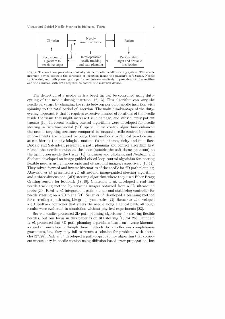
Fig. 2 The workflow presents a clinically viable robotic needle steering system. The needleinsertion device controls the direction of insertion inside the patient’s soft tissue. Needletip tracking and path planning are performed intra-operatively to provide control algorithmand the clinician with data required to control the insertion device.
The deflection of a needle with a bevel tip can be controlled using duty-cycling of the needle during insertion [12, 13]. This algorithm can vary theneedle curvature by changing the ratio between period of needle insertion withspinning to the total period of insertion. The main disadvantage of the duty-cycling approach is that it requires excessive number of rotations of the needleinside the tissue that might increase tissue damage, and subsequently patienttrauma [14]. In recent studies, control algorithms were developed for needlesteering in two-dimensional (2D) space. These control algorithms enhancedthe needle targeting accuracy compared to manual needle control but someimprovements are required to bring these methods to clinical practice suchas considering the physiological motion, tissue inhomogeneity and fluid flow.DiMaio and Salcudean presented a path planning and control algorithm thatrelated the needle motion at the base (outside the soft-tissue phantom) tothe tip motion inside the tissue [15]. Glozman and Shoham, and Neubach andShoham developed an image-guided closed-loop control algorithm for steeringflexible needles using fluoroscopic and ultrasound images, respectively [16,17].They solved forward and inverse kinematics of the needle for 2D path planning.Abayazid et al. presented a 2D ultrasound image-guided steering algorithm,and a three-dimensional (3D) steering algorithm where they used Fiber BraggGrating sensors for feedback [18, 19]. Chatelain et al. developed a real-timeneedle tracking method by servoing images obtained from a 3D ultrasoundprobe [20]. Reed et al. integrated a path planner and stabilizing controller forneedle steering on a 2D plane [21]. Seiler et al. developed a planning methodfor correcting a path using Lie group symmetries [22]. Hauser et al. developeda 3D feedback controller that steers the needle along a helical path, althoughresults were evaluated in simulation without physical experiments [23].
Several studies presented 2D path planning algorithms for steering flexibleneedles, but our focus in this paper is on 3D steering [15, 24–26]. Duindamet al. presented fast 3D path planning algorithms based on inverse kinemat-ics and optimization, although these methods do not offer any completenessguarantees, i.e., they may fail to return a solution for problems with obsta-cles [27,28]. Park et al. developed a path-of-probability algorithm that consid-ers uncertainty in needle motion using diffusion-based error propagation, but
4 Momen Abayazid et al.
the presence of obstacles affects the completeness of the planner [29]. Several3D path planning algorithms have been introduced that are based on Rapidly-exploring Random Trees (RRTs) [30, 31]. Our approach integrates ideas fromPatil et al. to quickly compute feasible, collision-free paths in 3D that solvesthe problem of failure in providing the path during presence of obstacles [31].
The proposed system, depicted in Fig. 2, is a step forward to achieve a clin-ically viable robotic needle steering system. The anatomical regions of interestin the patient are acquired pre-operatively using ultrasound images. Based onthe images, the clinician identifies the target location and sensitive structuressuch as glands or blood vessels and other obstacles such as bones. The pathplanning algorithm generates a needle trajectory to avoid obstacles and reachthe target. The planner generates new paths intra-operatively based on theupdated needle tip position (obtained from ultrasound images) and target po-sition during insertion. The needle insertion procedure is autonomous undersupervision of the clinician.
In the current study, we integrate the presented 3D tracking, path planningand control algorithms to steer a bevel-tipped flexible needle to reach a targetin 3D space while avoiding obstacles. The proposed control algorithm providesa reduced number of needle rotations to reach the target location to minimizetissue damage. The algorithms are validated by conducting insertion experi-ments into a soft-tissue phantom and biological tissue (chicken breast) whileavoiding virtual and real obstacles. The contributions of this work include:
– The use of ultrasound-based 3D needle tracking combined with 3D real-time path planning for avoiding real obstacles.
– 3D steering and path planning for needle insertion into biological tissue.– Experimental evaluation of needle steering towards a moving target while
avoiding more than one moving obstacle.
In the following section, we describe the ultrasound-based needle tip track-ing algorithm. We then describe the path planning method and the controlalgorithm, which reduces the number of needle rotations inside soft tissue toreduce patient trauma. Finally, we present our results in soft-tissue phantomsand biological tissue.
2 Three-Dimensional Needle Tracking
We use a high resolution 2D ultrasound transducer to obtain the needle tippose during insertion. The resolution of the ultrasound image is 0.12 mm perpixel. The ultrasound transducer is placed to visualize the tip, and orientatedperpendicular to the needle insertion direction (X-axis of frame (Ψ0)) as shownin Fig 3. The resulting ultrasound image shows a radial cross-sectional viewof the needle. The cross-section of the needle does not look circular in theultrasound image due to reverberation artifacts [32]. These artifacts occur dueto bouncing of the ultrasound waves between materials of different acousticimpedance such as the needle and the surrounding tissue. The resulting arti-fact visible in ultrasound images has a tail-shaped structure of equally spaced

Ultrasound-Guided Needle Steering in Biological Tissue 5
echoes along the sound wave. The length of the tail-shaped structure dependson the bouncing echoes that are received by the transducer. The reverberationartifact is often referred to as the comet tail artifact (CTA) [33]. An imageprocessing algorithm is used to determine the centroid of the needle in theultrasound images. The needle in ultrasound images is enhanced by a seriesof basic image processing techniques, including median filtering, thresholding,and erosion and dilation, as shown in Fig. 3. Some extra processing steps areperformed to remove artifacts that appear in ultrasound images while scanningbiological tissue (chicken breast). The ultrasound image is filtered to eliminatethe speckles that look similar to the needle tip. This is achieved by applyingan additional erosion step and by reducing the image intensity gain using theultrasound device settings.
The 2D ultrasound transducer needs to compensate for needle tip motionalong the x-axis of frame (Ψ0). A positioning device is used to control the ultra-sound transducer. The positioning device moves the transducer correspondingto the needle motion to provide ultrasound images of the needle tip duringinsertion. This allows the needle tip pose to be expressed in the fixed refer-ence frame using a series of coordinate transformations between frames (Ψu,Ψp and Ψ0). Further details regarding coordinate transformations and controlof the transducer motion are presented in the work of Vrooijink et al. [34]. The
YX
Z
X
Z
Y
Ψt
Ψt̂
YX
Z
Ψ0
YX
Z
Ψp
YX
Z
Ψu
Needle+λ −λ
A
B
Ultrasound imageY
X
Z
Ψn
(a) (b) (c) (d) (e)
(yc, zc)
Fig. 3 Overview of the various coordinate systems and the image processing techniquesused to evaluate the needle tip pose with respect to the fixed reference frame (Ψ0). The fixedreference frame (Ψ0) is located at the entry point of the needle in the soft-tissue phantom.Frame (Ψn) is fixed at the needle insertion device end-effector. Frame (Ψp) is fixed at theultrasound transducer end-effector. Frame (Ψt) is located at the needle tip, while frame (Ψt̂)is located at the needle tip as determined by the tracking algorithm. The aberration intransducer position along the insertion axis (x-axis of frame (Ψ0)) is given by ±λ. Theperpendicular placed 2D ultrasound transducer provides a radial cross-sectional view of theneedle which is affected by the comet tail artifact (CTA). An image processing methodologyis used to evaluate the needle centroid location in the ultrasound image frame (Ψu). (a)A median filter is applied to suppress speckle in the ultrasound image. (b) Thresholdingis performed to obtain a binary image. (c) Erosion and subsequently dilation is applied toremove the remaining speckle. (d) A feature extraction algorithm based on Hough transformis applied to determine a line segment denoted AB to describe the needle with CTA. (e) Theneedle centroid (yc,zc) is evaluated as the red circle, from A which represents a point on thesurface of the needle in the direction of B at a distance equal to the radius of the needle.

6 Momen Abayazid et al.
tracking algorithm is evaluated in gelatin phantoms and the mean errors of theneedle tip position alongX-, Y - and Z-axes (frame (Ψ0)) are 0.64 mm, 0.25 mmand 0.27 mm, respectively, using insertion velocities between 1− 5 mm/s.
3 Three-Dimensional Needle Path Planning and Control
The tracking algorithm determines the needle tip location for feedback to thecontrol system. The control system incorporates a path planning algorithmto generate the optimal needle trajectory towards the target. In the currentsection, we describe the 3D path planning and control algorithms.
3.1 Path Planning
We use a 3D path planning algorithm to enable the needle to reach a tar-get while avoiding obstacles in a 3D environment [31]. Using feedback fromultrasound imaging, the system steers the needle to approximately track theplanned path using the control algorithm described in Sec. 3.2.
For path planning, the system uses a customized RRT, a sampling-basedmethod for path planning [35]. The main advantage of using an RRT is thatour implementation is fast enough for real-time path planning during insertionif the needle is inserted with the insertion velocities used in clinical applications(0.4− 10 mm/s) [36]. To enable fast performance, our path planner makes useof reachability-guided sampling for efficient expansion of the rapidly-exploringsearch tree [37]. We also relax the constraint of constant-curvature needle tra-jectories by assuming that the controller can realize bounded-curvature needletrajectories by alternating the bevel tip direction. These customizations helpus to reduce the computational time compared to prior sampling-based plan-ners and make the path planner suitable for closed-loop needle steering [30].We refer the reader to Patil et al. for additional details on the planning algo-rithm [31].
Given pre-operative medical images, the clinician can specify the insertionlocation, the target location, and the geometry of obstacles, which can includesensitive structures such as glands or blood vessels as well as impenetrablestructures such as bones. After specifying the entire environment, the pathplanner computes a path that (1) reaches the target, and (2) is feasible, i.e.,avoids obstacles. The output of the path planning algorithm is a sequence ofmilestones along the path defined at 6 mm intervals. The control algorithmdiscussed in Sec. 3.2 begins by steering the needle toward the first milestonealong the path. As soon as a milestone is reached, the control algorithm steersthe needle toward the next milestone along the path.
Since the obstacles or target may move during the procedure, the systemoperates in a closed-loop fashion by replanning every second. At each replan-ning step, a path is computed from the needle tip pose that is estimated by theneedle tip tracking algorithm. The path planner also uses the actual positions
Ultrasound-Guided Needle Steering in Biological Tissue 7
pxtar
tip
X
Z
(b) (d) d
tar
rcon
rcon
rcur
ccon
YX
Z
ª0
Needle
Reachable region
Y
X
Z
ª t
Y
Z
ª t
ª t
µ
Target
Path planning algorithm Control algorithm
Needle
Milestones
ObstaclesFeasible path
(a)(c)
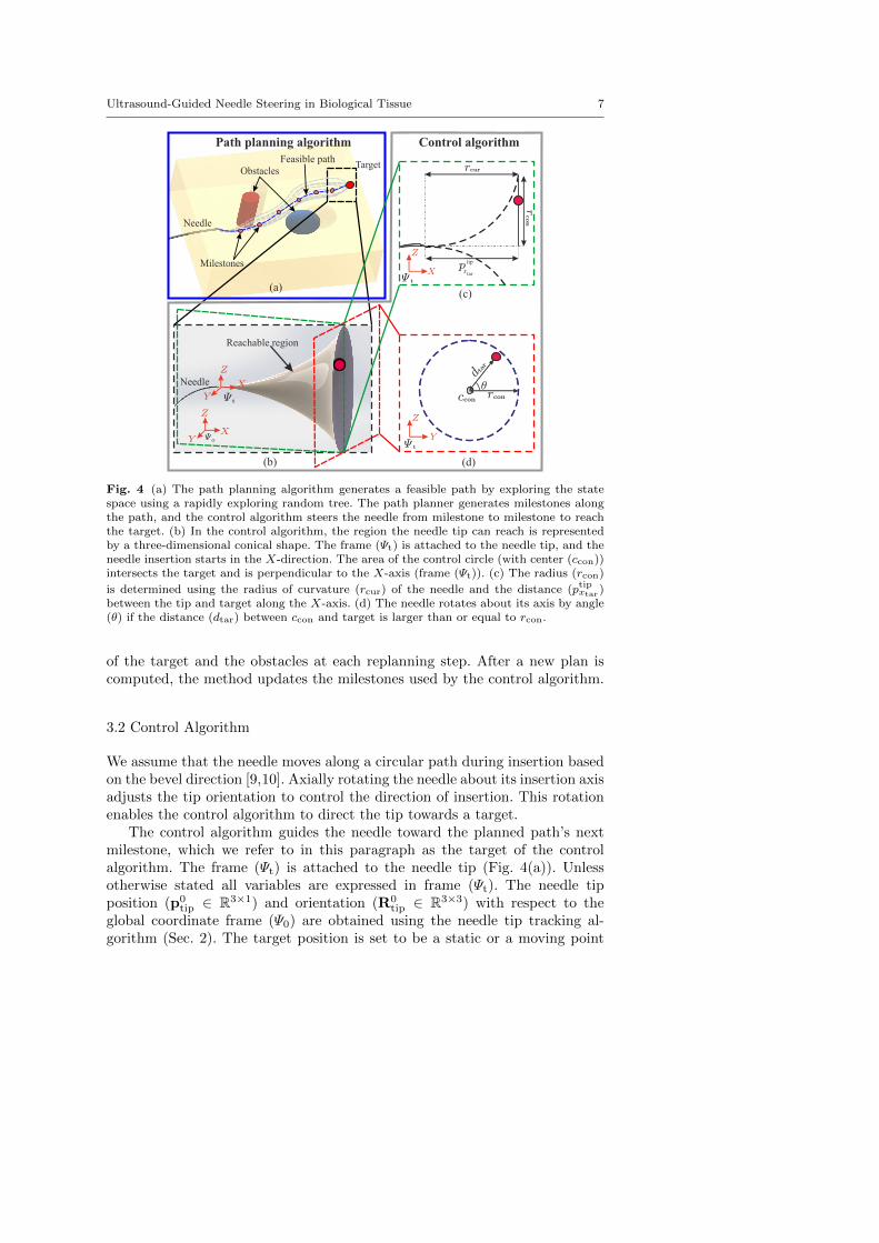
Fig. 4 (a) The path planning algorithm generates a feasible path by exploring the statespace using a rapidly exploring random tree. The path planner generates milestones alongthe path, and the control algorithm steers the needle from milestone to milestone to reachthe target. (b) In the control algorithm, the region the needle tip can reach is representedby a three-dimensional conical shape. The frame (Ψt) is attached to the needle tip, and theneedle insertion starts in the X-direction. The area of the control circle (with center (ccon))intersects the target and is perpendicular to the X-axis (frame (Ψt)). (c) The radius (rcon)
is determined using the radius of curvature (rcur) of the needle and the distance (ptipxtar )between the tip and target along the X-axis. (d) The needle rotates about its axis by angle(θ) if the distance (dtar) between ccon and target is larger than or equal to rcon.
of the target and the obstacles at each replanning step. After a new plan iscomputed, the method updates the milestones used by the control algorithm.
3.2 Control Algorithm
We assume that the needle moves along a circular path during insertion basedon the bevel direction [9,10]. Axially rotating the needle about its insertion axisadjusts the tip orientation to control the direction of insertion. This rotationenables the control algorithm to direct the tip towards a target.
The control algorithm guides the needle toward the planned path’s nextmilestone, which we refer to in this paragraph as the target of the controlalgorithm. The frame (Ψt) is attached to the needle tip (Fig. 4(a)). Unlessotherwise stated all variables are expressed in frame (Ψt). The needle tipposition (p0
tip ∈ R3×1) and orientation (R0tip ∈ R3×3) with respect to the
global coordinate frame (Ψ0) are obtained using the needle tip tracking al-gorithm (Sec. 2). The target position is set to be a static or a moving point
8 Momen Abayazid et al.
(a) (b)
(f)
e =0.25±0.07 mmµ2
e =0.32±0.10 mmµ6
(c)
e =0.38±0.19 mmµ5
Target motion
Biologicaltissue Virtual moving
obstacles
Realobstacles
e =0.34±0.11 mmµ4
e =0.24±0.09 mmµ1
Target
Needle
Virtualobstacles
Planned path
(d) (e)
e =0.26±0.11 mmµ3
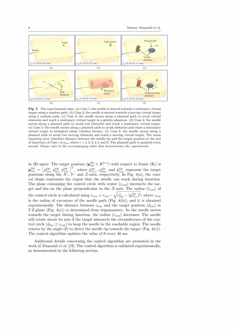
Fig. 5 The experimental cases. (a) Case 1: the needle is steered towards a stationary virtualtarget using a random path. (b) Case 2: the needle is steered towards a moving virtual targetusing a random path. (c) Case 3: the needle moves along a planned path to avoid virtualobstacles and reach a stationary virtual target in a gelatin phantom. (d) Case 4: the needlemoves along a planned path to avoid real obstacles and reach a stationary virtual target.(e) Case 5: the needle moves along a planned path to avoid obstacles and reach a stationaryvirtual target in biological tissue (chicken breast). (f) Case 6: the needle moves along aplanned path to avoid two moving obstacles and reach a moving virtual target. The meantargeting error (absolute distance between the needle tip and the target position at the endof insertion) of Case i is eµi, where i = 1, 2, 3, 4, 5 and 6. The planned path is updated everysecond. Please refer to the accompanying video that demonstrates the experiments.
in 3D space. The target position (ptiptar ∈ R3×1) with respect to frame (Ψt) is
ptiptar =
[ptipxtar
ptipytarptipztar
]T, where ptipxtar
, ptipytarand ptipztar represent the target
positions along the X-, Y - and Z-axes, respectively. In Fig. 4(a), the coni-cal shape represents the region that the needle can reach during insertion.The plane containing the control circle with center (ccon) intersects the tar-get and lies on the plane perpendicular to the X-axis. The radius (rcon) of
the control circle is calculated using rcon = rcur −√r2cur − (ptipxtar)
2, where rcuris the radius of curvature of the needle path (Fig. 4(b)), and it is obtainedexperimentally. The distance between ccon and the target position (dtar) inY Z-plane (Fig. 4(c)) is determined from trigonometry. As the needle movestowards the target during insertion, the radius (rcon) decreases. The needlewill rotate about its axis if the target intersects the circumference of the con-trol circle (dtar ≥ rcon) to keep the needle in the reachable region. The needlerotates by the angle (θ) to direct the needle tip towards the target (Fig. 4(c)).The control algorithm updates the value of θ every 40 ms.
Additional details concerning the control algorithm are presented in thework of Abayazid et al. [19]. The control algorithm is validated experimentally,as demonstrated in the following section.
Ultrasound-Guided Needle Steering in Biological Tissue 9
4 Experiments
In this section, we present the experimental setup used to insert the needleinto the soft-tissue, the experimental plan, and the results.
4.1 Setup
The experimental setup is divided into two parts. First, the insertion deviceallows the needle to be inserted and rotated about its axis. The details of theneedle insertion device are presented in previous work [18]. Second, a trans-ducer control device that permits the ultrasound transducer to move in threedegrees of freedom, as shown in Fig. 1. The 18 MHz transducer (18L6 HD witha mean ultrasound beam width of 0.4 mm) is connected to a Siemens Acu-son S2000 ultrasound machine (Siemens AG, Erlangen, Germany). Additionalinformation about the transducer control device is presented by Vrooijink etal. [34].
The needle is inserted into a soft-tissue phantom made up of a gelatinmixture [19]. Silica powder is added to the mixture to mimic the acousticscattering of human tissue. The flexible needle is made of Nitinol alloy (nickeland titanium). The Nitinol needle has a diameter of 0.5 mm with a bevel angle(at the tip) of 30◦.
4.2 Results
In the current section, different experimental scenarios are conducted to eval-uate the performance of the proposed needle tracking, path planning and con-trol algorithms. The needle radius of curvature in the phantom is determinedempirically (270 mm) [19]. A safety margin is added to the needle curvaturevalue to compensate for variations or disturbances that may take place duringinsertion. The needle is inserted with a velocity of 1 mm/s. Each experimentalcase is performed five times. The experimental cases are depicted in Fig. 5.
In Case 1 and Case 2, the steering algorithm controls the needle to reacha stationary and a moving virtual target, respectively (no path planning isapplied) (Fig. 5(a) and (b)). In Case 3 and Case 4, path planning is appliedpre-operatively to generate the optimal trajectory between the needle tip andthe target. In Case 3, virtual obstacles used while in Case 4, real obstacles areembedded into the gelatin phantom. The real obstacles are 3D-printed plasticshapes (Fig. 5 (d)). The phantom is scanned pre-operatively to localize the realobstacles in the soft-tissue phantom. The obstacles appear dark in the ultra-sound image frames. The images are inverted and a threshold is set to obtaina binary image. The location of the obstacle is determined by calculating thecentroid of the white region in each image frame (obstacle after inversion) andthen along the frames that include the obstacle. The obtained obstacle loca-tion is exported to the path planning algorithm. Our system assumes that the

10 Momen Abayazid et al.
shape of obstacles are recognized by the planner, which requires segmentingobstacles in pre-operative medical imaging. The segmentations can be pro-duced manually by a physician (for fixed obstacles obstacles) or automaticallyusing segmentation software. (We note that automatic segmentation is a chal-lenging problem that is actively being studied and is beyond the scope of thiswork.) The steering algorithm moves the needle along the generated path toavoid the obstacles and reach the target using milestones (Fig. 5(c) and (d)).In Case 5, the needle is steered towards a virtual target in biological tissueembedded in a gelatin phantom while avoiding virtual obstacles as shown inthe lower inset in Fig. 1 and Fig. 5(e). In Case 6, the virtual target movesaway from the needle tip in the direction of the needle orientation with a ve-locity of 0.125 mm/s. This results in a target motion of 10 mm. The targetmoves in the direction of needle insertion to simulate the effect of tissue de-formation caused by the needle compression on the surrounding tissue. Thepath is updated every second to avoid the moving obstacles and reach themoving target. The obstacles move in the direction of the needle path witha velocity of 0.06 mm/s (Fig. 5(f)). The targeting error is the absolute dis-tance between the target position that is pre-defined and needle tip positionobtained from the needle tracking algorithm described in Section 2. The meantargeting errors for all experimental cases are provided in Fig. 5. Please referto the accompanying video that demonstrates the experiments.
5 Discussion
This study combines a 3D real-time ultrasound-based needle tracking withpath planning and control algorithms. These algorithms are used to accuratelysteer bevel-tipped flexible needles towards stationary and moving targets whileavoiding virtual and real obstacles. The main advantage of the proposed con-trol algorithm is that the needle rotates only when a change of the direction ofinsertion is required. This reduces the number of full rotations of the needle,and thus has the potential to reduce patient trauma [14]. In the implementa-tion of the control algorithm, the needle can rotate in both directions to reducethe angle of rotation. The reduction of rotation angle suppresses the effect oftorsion along the needle shaft which reduces the error between its orientationat the tip and base. Experiments were also performed using duty-cycling algo-rithm and compared to the proposed control algorithm to estimate its influenceon the number of needle rotations (tissue damage). For the same insertion dis-tance and path planner settings, the duty-cycling control algorithm required51 complete rotations of the needle, while the proposed algorithm performedthe procedure with just 11 complete rotations.
Experiments are performed to evaluate the targeting accuracy of the pro-posed system. Six experimental cases are performed to validate the tracking,path planning and control algorithms. The needle is steered in gelatin phan-tom and biological tissue. The needle visibility in ultrasound images is dete-riorated due to shadows surrounding the solid obstacles during insertion, and

Ultrasound-Guided Needle Steering in Biological Tissue 11
Target Needle tip+
Fig. 6 The ultrasound image shows a cross-section of the target (φ 6 mm) embedded in asoft-tissue phantom at the end of the needle insertion, and the tip penetrating the target.
this affects the targeting accuracy in Case 4. The targeting error increaseswhile steering in biological tissue (Case 5) due to tissue inhomogeneity. Thiscauses variation in the needle behavior during insertion. The experimentalresults show that the mean targeting error ranges between 0.24 ± 0.09 mmand 0.38 ± 0.19 mm. An extra experiment is conducted to validate the pro-posed system using a real φ 6 mm target made of an aqueous solution of20 wt.% polyvinyl alcohol (PVA) (SigmaAldrich Chemie B.V., Zwijndrecht,The Netherlands). This experiment is performed five times, and the insertiondistance ranges between 86 and 102 mm. The target and the obstacle are sta-tionary, and their positions are determined using a pre-operative ultrasoundscan. The needle tip reaches the target in each experimental trial. Fig. 6 showsa representative ultrasound image of the cross-section of the target penetratedby the needle tip.
The needle insertions performed in the current study are conducted in anexperimental environment where the needle is inserted into a static phantomthat contains two types of materials (gelatin and chicken breast tissue). In aclinical environment, we expect more variables that may reduce the targetingaccuracy such as physiological motion, fluid flow and tissue inhomogeneity.Further improvements are required to bring the system to the clinical practice.In future work, the ultrasound needle tracking device will be adapted to trackthe needle tip while scanning curved surfaces. A technique should also bedeveloped for 3D reconstruction of the shape of targets and obstacles pre-operatively and then tracking of real targets and obstacles in real-time duringinsertion into biological tissue in order to improve the targeting accuracy. Thesteering system can be extended to detect the patient movements that occurduring needle insertion such as respiration and fluid flow. A model should bedeveloped to estimate the needle curvature in different heterogeneous tissue foraccurate targeting. Real-time shared control between the steering algorithmand the operator will be established to achieve a practical system for clinicaloperations.
Acknowledgements This work was supported by funds from the Netherlands Organiza-tion for Scientific Research (NWO - project:11204), by the United States National Science

12 Momen Abayazid et al.
Foundation under awards #IIS-0905344 and #IIS-1149965, and by the United States Na-tional Institutes of Health under awards #R21EB011628 and #R21EB017952.
Conflict of interest
M. Abayazid, G.J.Vrooijink, S. Patil, R. Alterovitz and S. Misra declare thatthey have no conflict of interest with other people or organizations that wouldinappropriately influence this work.
References
1. E. M. Boctor, M. A. Choti, E. C. Burdette, and R. J. Webster III, “Three-dimensionalultrasound-guided robotic needle placement: an experimental evaluation,” The Inter-national Journal of Medical Robotics and Computer Assisted Surgery, vol. 4, no. 2, pp.180–191, 2008.
2. L. B. Kratchman, M. M. Rahman, J. R. Saunders, P. J. Swaney, and R. J. Webster III,“Toward robotic needle steering in lung biopsy: a tendon-actuated approach,” in Pro-ceedings of the Society of Photographic Instrumentation Engineers (SPIE), MedicalImaging: Visualization, Image-Guided Procedures, and Modeling, K. H. Wong and D. R.Holmes III, Eds., vol. 7964. Florida, USA, February 2011, pp. 79 641I–1–79 641I–8.
3. P. Beddy, R. D. Rangarajan, and E. Sala, “Role of mri in intracavitary brachyther-apy for cervical cancer: What the radiologist needs to know,” American Journal ofRoentgenology, vol. 196, no. 3, pp. W341–W347, March 2011.
4. R. Seifabadi, S.-E. Song, A. Krieger, N. Cho, J. Tokuda, G. Fichtinger, and I. Iorda-chita, “Robotic system for mri-guided prostate biopsy: feasibility of teleoperated needleinsertion and ex vivo phantom study,” International Journal of Computer AssistedRadiology and Surgery, vol. 7, no. 2, pp. 181–190, 2012.
5. N. Abolhassani, R. V. Patel, and M. Moallem, “Needle insertion into soft tissue: Asurvey,” Medical Engineering and Physics, vol. 29, no. 4, pp. 413–431, 2007.
6. A. Grant and J. Neuberger, “Guidelines on the use of liver biopsy in clinical practice,”Journal of Gastroenterlogoly and Hepatology, vol. 45, no. Supplement IV, pp. IV1–IV11,1999.
7. V. Kallem and N. J. Cowan, “Image-guided control of flexible bevel-tip needles,” in Pro-ceedings of the IEEE International Conference on Robotics and Automation (ICRA).Rome, Italy, April 2007, pp. 3015–3020.
8. N. J. Cowan, K. Goldberg, G. S. Chirikjian, G. Fichtinger, K. B. Reed, V. Kallem,W. Park, S. Misra, and A. M. Okamura, Surgical Robotics. Springer US, 2011, ch.Robotic Needle Steering: Design, Modeling, Planning, and Image Guidance, pp. 557–582.
9. R. J. Webster III, J. S. Kim, N. J. Cowan, G. S. Chirikjian, and A. M. Okamura, “Non-holonomic modeling of needle steering,” International Journal of Robotics Research,vol. 25, no. 5-6, pp. 509–525, 2006.
10. S. Misra, K. B. Reed, B. W. Schafer, K. T. Ramesh, and A. M. Okamura, “Mechanicsof flexible needles robotically steered through soft tissue,” International Journal ofRobotics Research, vol. 29, no. 13, pp. 1640–1660, 2010.
11. K. G. Yan, T. Podder, D. Xiao, Y. Yu, T. Liu, C. W. S. Cheng, and W. S. Ng, “An im-proved needle steering model with online parameter estimator,” The International Jour-nal for Computer Assisted Radiology and Surgery, vol. 1, no. 4, pp. 205–212, September2006.
12. J. A. Engh, G. Podnar, S. Y. Khoo, and C. N. Riviere, “Flexible needle steering systemfor percutaneous access to deep zones of the brain,” in Proceedings of the IEEE AnnualNortheast Bioengineering Conference (NEBEC). Easton, USA, April 2006, pp. 103–104.

Ultrasound-Guided Needle Steering in Biological Tissue 13
13. D. S. Minhas, J. A. Engh, M. M. Fenske, and C. N. Riviere, “Modeling of needle steeringvia duty-cycled spinning,” in Proceedings of the IEEE International Conference onEngineering in Medicine and Biology Society (EMBC). Lyon, France, August 2007,pp. 2756–2759.
14. P. J. Swaney, J. Burgner, H. B. Gilbert, and R. J. Webster, “A flexure-based steerableneedle: High curvature with reduced tissue damage,” IEEE Transactions on BiomedicalEngineering, vol. 60, no. 4, pp. 906–909, 2013.
15. S. P. DiMaio and S. E. Salcudean, “Needle steering and model-based trajectory plan-ning,” in Proceedings of the International Conference on Medical Image Computing andComputer-Assisted Intervention (MICCAI), vol. 2878. Montral, Canada, November2003, pp. 33–40.
16. D. Glozman and M. Shoham, “Image-guided robotic flexible needle steering,” IEEETransactions on Robotics, vol. 23, no. 3, pp. 459–467, 2007.
17. Z. Neubach and M. Shoham, “Ultrasound-guided robot for flexible needle steering,”IEEE Transactions on Biomedical Engineering, vol. 57, no. 4, pp. 799–805, 2010.
18. M. Abayazid, R. J. Roesthuis, R. Reilink, and S. Misra, “Integrating deflection mod-els and image feedback for real-time flexible needle steering,” IEEE Transactions onRobotics, vol. 29, no. 2, pp. 542–553, 2013.
19. M. Abayazid, M. Kemp, and S. Misra, “3d flexible needle steering in soft-tissue phan-toms using fiber bragg grating sensors,” in Proceedings of the IEEE International Con-ference on Robotics and Automation (ICRA). Karlsruhe, Germany, May 2013, pp.5823–5829.
20. P. Chatelain, A. Krupa, and M. Marchal, “Real-time needle detection and trackingusing a visually servoed 3d ultrasound probe,” in Proceedings of the IEEE internationalconference on Robotics and Automation. Karlsruhe, Germany, May 2013, pp. 1668–1673.
21. K. B. Reed, A. Majewicz, V. Kallem, R. Alterovitz, K. Goldberg, N. J. Cowan, andA. M. Okamura, “Robot-assisted needle steering,” IEEE Robotics Automation Maga-zine, vol. 18, no. 4, pp. 35–46, 2011.
22. K. Seiler, S. P. N. Singh, S. Sukkarieh, and H. F. Durrant-Whyte, “Using lie groupsymmetries for fast corrective motion planning,” International Journal of Robotics Re-search, vol. 31, no. 2, pp. 151–166, 2012.
23. K. Hauser, R. Alterovitz, N. Chentanez, A. M. Okamura, and K. Goldberg, “Feedbackcontrol for steering needles through 3d deformable tissue using helical paths,” in Pro-ceedings of Robotics: Science and Systems (RSS), vol. 37. Seattle, USA, June 2009.
24. R. Alterovitz, M. Branicky, and K. Goldberg, “Motion planning under uncertaintyfor image-guided medical needle steering,” International Journal of Robotic Research,vol. 27, no. 11-12, pp. 1361–1374, 2008.
25. A. Asadian, R. M. Kermani, and R. V. Patel, “Robot-assisted needle steering using acontrol theoretic approach,” Journal of Intelligent and Robotic Systems, vol. 62, no.3–4, pp. 397–418, 2011.
26. M. C. Bernardes, B. V. Adorno, P. Poignet, and G. A. Borges, “Semi-automatic needlesteering system with robotic manipulator,” in Proceedings of the IEEE InternationalConference on Robotics and Automation (ICRA). St. Paul, USA, May 2012, pp.1595–1600.
27. V. Duindam, R. Alterovitz, S. Sastry, and K. Goldberg, “Screw-based motion planningfor bevel-tip flexible needles in 3d environments with obstacles,” in Proceedings of theIEEE International Conference on Robotics and Automation (ICRA). Pasadena, USA,May 2008, pp. 2483–2488.
28. V. Duindam, J. Xu, R. Alterovitz, S. Sastry, and K. Goldberg, “Three-dimensional mo-tion planning algorithms for steerable needles using inverse kinematics,” InternationalJournal of Robotics Research, vol. 29, no. 7, pp. 789–800, 2010.
29. W. Park, Y. Wang, and G. S. Chirikjian, “The path-of-probability algorithm for steeringand feedback control of flexible needles,” International Journal of Robotics Research,vol. 29, no. 7, pp. 813–830, 2010.
30. J. Xu, V. Duindam, R. Alterovitz, and K. Goldberg, “Motion planning for steerableneedles in 3d environments with obstacles using rapidly-exploring random trees andbackchaining,” in Proceedings of the IEEE International Conference on AutomationScience and Engineering (CASE). Washington, D.C., USA, August 2008, pp. 41–46.

14 Momen Abayazid et al.
31. S. Patil and R. Alterovitz, “Interactive motion planning for steerable needles in 3denvironments with obstacles,” in Proceedings of IEEE RAS and EMBS InternationalConference on Biomedical Robotics and Biomechatronics (BioRob). Tokyo, Japan,September 2010, pp. 893–899.
32. J. E. Aldrich, “Basic physics of ultrasound imaging,” Critical Care Medicine, vol. 35,no. 5, pp. S131–S137, 2007.
33. J. Huang, J. Triedman, N. Vasilyev, Y. Suematsu, R. Cleveland, and P. Dupont, “Imag-ing artifacts of medical instruments in ultrasound-guided interventions,” Journal ofUltrasound in Medicine, vol. 26, no. 10, pp. 1303–1322, 2007.
34. G. J. Vrooijink, M. Abayazid, and S. Misra, “Real-time three-dimensional flexible needletracking using two-dimensional ultrasound,” in Proceedings of the IEEE InternationalConference on Robotics and Automation (ICRA). Karlsruhe, Germany, May 2013, pp.1680–1685.
35. S. M. LaValle, Planning Algorithms. Cambridge University Press, 2006.36. S. P. DiMaio and S. E. Salcudean, “Needle insertion modelling and simulation,” in Pro-
ceedings of the IEEE International Conference on Robotics and Automation (ICRA).Washington, D.C., USA, May 2002, pp. 2098–2105.
37. A. Shkolnik, M. Walter, and R. Tedrake, “Reachability-guided sampling for planningunder differential constraints,” in Proceeding of the IEEE International Conference onRobotics and Automation (ICRA). Kobe, Japan, May 2009, pp. 2859–2865.


![Ultrasound Guided Vascular Access[2]](https://img.dokumen.tips/doc/110x75/5420582a7bef0a06088b4679/ultrasound-guided-vascular-access2.jpg)