Embed Size (px)
Citation preview

The Open Civil Engineering Journal, 2011, 5, 109-115 109
1874-1495/11 2011 Bentham Open
Open Access
Experimental and Numerical Study on Bar-Reinforced Concrete Filled Steel Tubular Columns Under Axial Compression
Jinsheng Han* and Shuping Cong
School of Civil Engineering and Architecture, Shandong University of Science and Technology, Qingdao 266510, China
Abstract: The behaviors of bar-reinforced concrete filled steel tubular columns subjected to axial load were studied. One
plain concrete filled steel tubular column and three bar-reinforced concrete filled steel tubular columns were tested. The
deformation of specimens and the strain of steel tubes were measured. Based on experimental researches, a simple
numerical analysis method was presented to simulate the full load-deformation process of bar-reinforced concrete filled
steel tubular short columns subjected to axial compression. Firstly, the interaction process of steel tube and concrete was
analyzed, and then, the simplified constitutive models of steel tube and concrete were established on the base of previous
analysis results. Secondly, the relation between lateral and longitudinal strain of steel tube was analyzed based on
experimental results, and a simple method was presented to calculate the lateral strain of steel tube. This method was used
as the supplement to the constitutive models. Finally, a program was worked out to simulate the full load-deformation
process of bar-reinforced concrete filled steel tubular short columns. The program’s simulation results of both ultimate
bearing capacity and load-deformation curves are in good agreement with the experimental results.
Keywords: Bar-reinforced concrete filled steel tubular column, test, Interaction, Constitutive models, Load-deformation process, Numerical simulation.
1. INTRODUCTION
Bar-reinforced concrete filled steel tubular (CFST)
columns have a good advantage that they can satisfy the
practical need of fire resistance depending on the fire-
resistant ability of themselves, so the external fire-proof
protection layers are not necessary. As a result, a lot of
investigations have been carried out to research the fire
resistance and ultimate bearing capacity of bar-reinforced
CFST columns [1-3]. However, researches on the full
process of force-deformation of CFST column are relatively
scarce. Bar-reinforced CFST column is a typical confined
concrete because the core concrete is confined by steel tube.
Many of the previous research works on confined concrete
have been mainly focused on the concrete confined
by transverse reinforcement [4-7] or FRP [8-10]. It is
very easy to determine the confinement pressure which
is corresponding to the yield strength of transverse
reinforcement or FRP. But it is very different for bar-
reinforced CFST short columns which are confined by steel
tubes. Firstly, the confinement effect doesn’t exist at the
early stage of loading just as discussed as follows. Secondly,
after the appearance of the interaction between concrete and
steel tube, the lateral strain of steel tube needs to be
previously known to determine the stress of steel tube. The
lateral strain of steel tube is determined by the lateral
dilatational strain of core concrete, in turn, the dilatational
*Address correspondence to this author at the School of Civil Engineering
and Architecture, Shandong University of Science and Technology,
Qingdao 266510, China; Tel: +86-0532-86055792;
Fax: +86-0532-87199217; E-mail: [email protected]
strain of core concrete is influenced by the confinement
pressure from steel tube. So the core concrete and steel tube
interact and affect each other, and it’s very difficult and
complex to determine the lateral strain of steel tube and
calculate the stress state of steel tube and core concrete.
Based on experimental researches, the relation between
lateral and longitudinal strain of steel tube was analyzed, and
a simple method was presented to calculate the lateral strain
of steel tube and simulate the full load-deformation process
of bar-reinforced CFST short columns subjected to axial
compression.
2. EXPERIMENTAL STUDY
In order to study the behaviors of CFST columns
subjected to axial load, one plain concrete filled steel tubular
column and three bar-reinforced concrete filled steel tubular
columns were tested. The diameter of longitudinal
reinforcing bars is 20mm. The measured yield strength of
longitudinal reinforcing bars is 493MPa and that of shear
reinforcement is about 230MPa. The parameters of the test
specimens are listed in Table 1, and the details of the
specimens are shown in Fig. (1).
A series of strain rosettes were pasted at the upper,
middle and lower parts of the steel tubes as shown in Fig. (1)
to measure the longitudinal and lateral strains of steel tubes.
At each part, there were four strain rosettes called as A B C
D respectively. For convenience, the lateral strain measured
by each strain rosette is labeled as “1” and the longitudinal
strain is labeled as “2”. For example, “A1” indicates the
lateral strain measured by the strain rosette “A”.
110 The Open Civil Engineering Journal, 2011, Volume 5 Han and Cong
Fig. (1). Details of specimens.
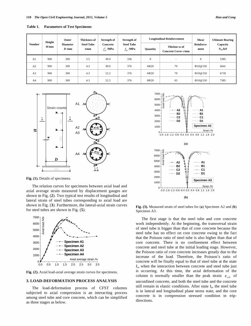
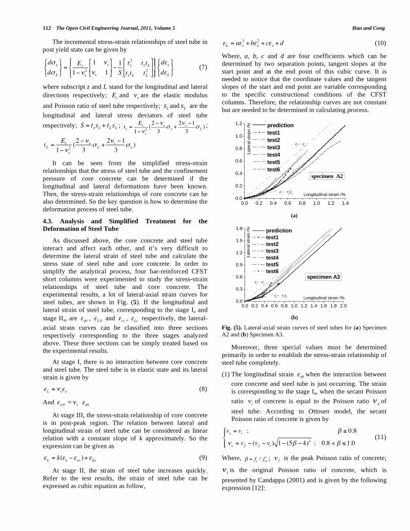
The relation curves for specimens between axial load and
axial average strain measured by displacement gauges are
shown in Fig. (2). Two typical test results of longitudinal and
lateral strain of steel tubes corresponding to axial load are
shown in Fig. (3). Furthermore, the lateral-axial strain curves
for steel tubes are shown in Fig. (5).
Fig. (2). Axial load-axial average strain curves for specimens.
3. LOAD-DEFORMATION PROCESS ANALYSIS
The load-deformation process of CFST columns
subjected to axial compression is an interacting process
among steel tube and core concrete, which can be simplified
as three stages as below.
Fig. (3). Measured strain of steel tubes for (a) Specimen A2 and (b)
Specimen A3.
The first stage is that the steel tube and core concrete
work independently. At the beginning, the transversal strain
of steel tube is bigger than that of core concrete because the
steel tube has no effect on core concrete owing to the fact
that the Poisson ratio of steel tube is also higher than that of
core concrete. There is no confinement effect between
concrete and steel tube at the initial loading stage. However,
the Poisson ratio of core concrete increases greatly due to the
increase of the load. Therefore, the Poisson’s ratio of
concrete will be finally equal to that of steel tube at the state
Ia, when the interaction between concrete and steel tube just
is occurring. At this time, the axial deformation of the
column is normally smaller than the peak strain c0 of
unconfined concrete, and both the steel tube and the concrete
still remain in elastic conditions. After state Ia, the steel tube
is in lateral and longitudinal plane stress state, and the core
concrete is in compression stressed condition in trip-
directions.
Table 1. Parameters of Test Specimens
Longitudinal Reinforcement
Number Height
H/mm
Outer
Diameter
D /mm
Thickness of
Steel Tube
t/mm
Strength of
Concrete
fck /MPa
Strength of
Steel Tube
fsk /MPa Quantity Thickne-ss of
Concrete Cover c/mm
Shear
Reinforce-
ment
Ultimate Bearing
Capacity
Nue/kN
A1 900 300 5.5 49.0 336 0 - 0 5385
A2 900 300 4.3 49.0 376 6 20 70 10@150 6641
A3 900 300 4.3 52.2 376 6 20 70 10@150 6718
A4 900 300 4.3 52.2 376 8 20 65 10@150 7385
D
H A C
B
D
A C
B
D
A C
B
D
A4
A2
A1
A3
Strain rosette
0.0 0.5 1.0 1.5 2.0 2.5 3.0 3.50
1000
2000
3000
4000
5000
6000
7000
Axi
al lo
ad /k
N
Axial average strain /%
Specimen A1 Specimen A2 Specimen A3 Specimen A4
0
1000
2000
3000
4000
5000
6000
7000
-2.0 -1.6 -1.2 -0.8 -0.4 0.0 0.4 0.8 1.2 1.6 2.0
Specimen A2
A1 B1 C1 D1
A2 B2 C2 D2
Strain /%
Axi
al lo
ad /
kN
(a)
0
1000
2000
3000
4000
5000
6000
7000
-2.0 -1.6 -1.2 -0.8 -0.4 0.0 0.4 0.8 1.2 1.6 2.0
A1 B1 C1 D1
A2 B2 C2 D2
Strain /%
Axi
al lo
ad
/kN
Specimen A3
(b)

Experimental and Numerical Study on Bar-Reinforced Concrete Filled The Open Civil Engineering Journal, 2011, Volume 5 111
The second stage is before the peak strain of core
concrete confined by steel tube. At this stage, the stress of
steel tube passes from elastic state to plastic state. In plastic
state, the lateral stress of steel tube will steadily increase
while the longitudinal stress decreases. At the same time,
the axial compressive strength and deformation capability
of core concrete, corresponding to the peak stress and
peak strain, increase gradually because of the significant
confinement of steel tube. Since the lateral stress of steel
tube is variable in the compress process, the peak stress and
peak strain of core concrete is also in the process of dynamic
growth. But the increase speed of the peak strain of core
concrete is smaller than the axial compressive strain of the
column. Ultimately, the peak strain of core concrete confined
by steel tube is equal to the axial compressive strain of the
column, and the critical state IIa arrives. At this stage, the
longitudinal stress of steel tube increases before plastic
condition and decreases after plastic condition, while the
lateral stress of steel tube and the stress of core concrete
increase continuously. In a certain state before core concrete
reaches its peak strain, the sum of the bearing capacity of
core concrete and steel tube reaches maximum, which is the
ultimate strength of the column.
The third stage is after the peak strain of core concrete
confined by the steel tube. After the second stage, the stress
of core concrete decreases with the strain increases even
though the confinement pressure still increases. At this stage,
the longitudinal stress of steel tube and core concrete
decrease continuously. Therefore, the strength of the column
is decreasing until the column is crushed.
4. THEORY OF NUMERICAL ANALYSIS
4.1. Basic Assumptions
(1) At the initial loading stage, both core concrete and steel
tube are compressed independently. There is no steel-
concrete interaction.
(2) After core concrete begins to be confined by steel tube,
the steel tube is in plane stress state and Mises yield rule
can be used to determine the stress-strain relationship. At
the same time, the core concrete is in triaxial
compressive stress state owing to the confinement of
steel tube. The stress in the column section is uniformly
distributed.
(3) Because the confinement effect applied to core concrete
by steel tube is uniform in any direction, the radial strain
and hoop strain of core concrete are equal, and the lateral
strain of steel tube and the hoop strain of core concrete
are also equal.
(4) Superposition method is used to consider the effect of
longitudinal reinforcements for the ultimate bearing
capacity of the column. But the effect of the stirrup is
ignored.
4.2. Simplified Stress-Strain Relationships of Core
Concrete and Steel Tube Core Concrete
The stress-strain relationships of unconfined concrete and
confined concrete are shown in Fig. (4) [11]. The expression
for the stress-strain curve of confined concrete is defined as
suggested by Popovics (1973), which is later modified by
Mander (1984) and is given by the following expression 4:
Fig. (4). General stress-strain curves for unconfined and confined
concrete.
fc =fccxr
r 1+ xr (1)
cc = c0[1+ 5( fcc / fc0 1)] (2)
Wherec
f and c
denote the longitudinal compressive stress
and strain, respectively; fcc and cc are the peak stress and
peak strain of confined concrete respectively; x = c / cc ;
r = Ec / (Ec Esec ) ; Esec = fcc / cc ; Ec = 5000 fc0 MPa;
c0 and fc0 stand for the peak strain and peak stress of
unconfined concrete.
Based on the William-Warnke failure criterion, the peak
stress of confined concrete with uniform lateral restraint can
be derived as follows:
fcc = fc0 ( 1.254 + 2.254 1+ 7.94 fl / fc0 2 fl / fc0 ) (3)
Where fl denotes the hoop stress (confinement pressure)
caused by steel tube, corresponding to the peak strain of
confined concrete.
The post-peak region of equation (1) is not used and
displaced by the expression suggested by Montoya (2004)
[5], which is given by
fc =fcc
A( c / fcc )2 B( c / fcc )+C +1.0
(4)
Where A = 0.25( fcc / ( c80 cc ))2; B = 2A / Esec ;
C = A / Esec2
; c80 stands for the strain in post-peak region
corresponding with 0.8 fcc , which can be given by
c80 = c0 (1.5 + (89.5 0.60 fc0 ) fl / fc0 ) (5)
Steel Tube
The stress-strain relationships of steel tube in pre-yield
state can be given by
z
L
=Es
1 s2
1 s
s 1z
L
(6)
Montoya Model
Mander Model
Esec
f c
c
Confined concrete
c0 cc
f /c0
f /cc
Unconfined concrete
112 The Open Civil Engineering Journal, 2011, Volume 5 Han and Cong
The incremental stress-strain relationships of steel tube in
post yield state can be given by
d z
d L
=Es
1 s2
1 s
s 11
S
tz2 tztL
tztL tL2
d z
d L
(7)
where subscript z and L stand for the longitudinal and lateral
directions respectively; Es and s are the elastic modulus
and Poisson ratio of steel tube respectively; z
s andL
s are the
longitudinal and lateral stress deviators of steel tube
respectively; S = tzsz + tL sL ; tz =Es
1 s2(2 s
3 z +2 s 1
3 L ) ;
tL =Es
1 s2(2 s
3 L +2 s 1
3 z )
It can be seen from the simplified stress-strain
relationships that the stress of steel tube and the confinement
pressure of core concrete can be determined if the
longitudinal and lateral deformations have been known.
Then, the stress-strain relationships of core concrete can be
also determined. So the key question is how to determine the
deformation process of steel tube.
4.3. Analysis and Simplified Treatment for the
Deformation of Steel Tube
As discussed above, the core concrete and steel tube
interact and affect each other, and it’s very difficult to
determine the lateral strain of steel tube and calculate the
stress state of steel tube and core concrete. In order to
simplify the analytical process, four bar-reinforced CFST
short columns were experimented to study the stress-strain
relationships of steel tube and core concrete. The
experimental results, a lot of lateral-axial strain curves for
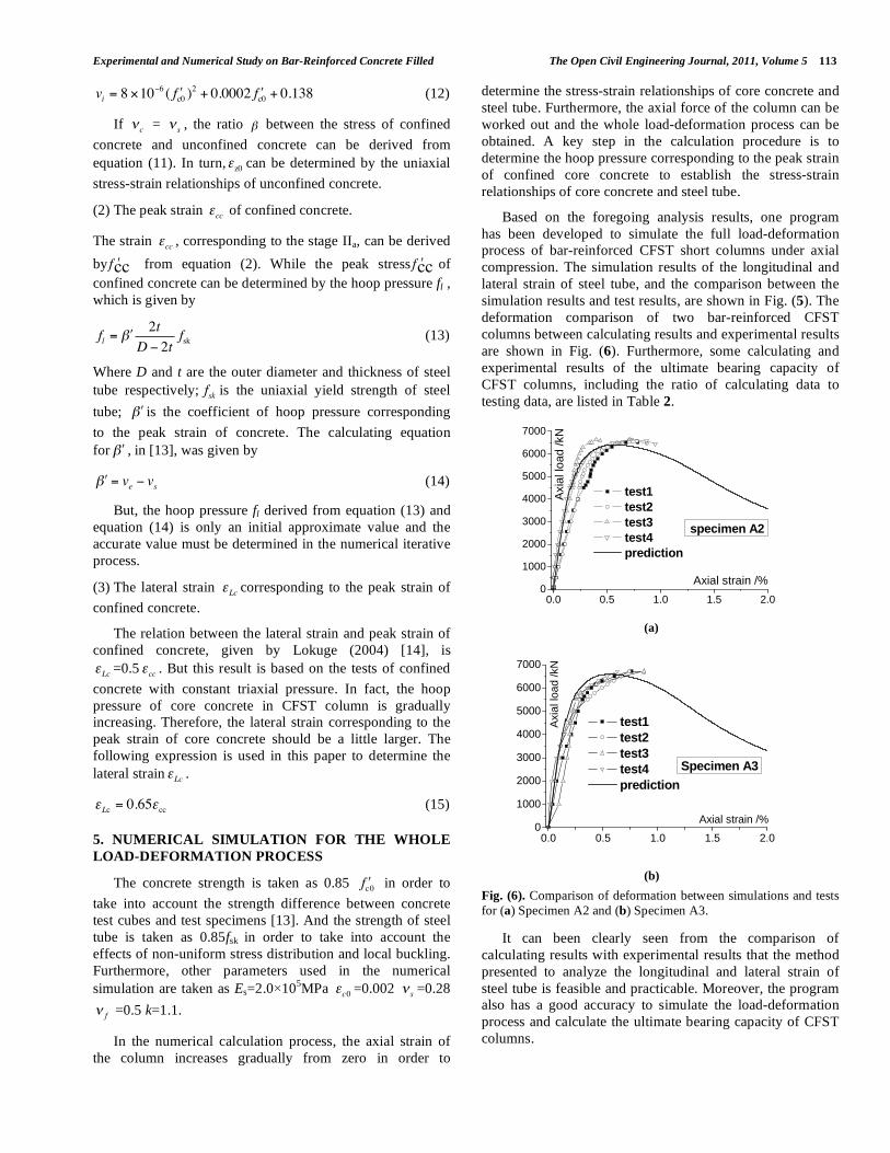
steel tubes, are shown in Fig. (5). If the longitudinal and
lateral strain of steel tube, corresponding to the stage Ia and
stage IIa, are z0 , L0 and cc , Lc respectively, the lateral-
axial strain curves can be classified into three sections
respectively corresponding to the three stages analyzed
above. These three sections can be simply treated based on
the experimental results.
At stage I, there is no interaction between core concrete
and steel tube. The steel tube is in elastic state and its lateral
strain is given by
L = s z (8)
And L0 = s z0
At stage III, the stress-strain relationship of core concrete
is in post-peak region. The relation between lateral and
longitudinal strain of steel tube can be considered as linear
relation with a constant slope of k approximately. So the
expression can be given as
L = k( z cc )+ Lc (9)
At stage II, the strain of steel tube increases quickly.
Refer to the test results, the strain of steel tube can be
expressed as cubic equation as follow,
L = a z3+ b z
2+ c z + d (10)
Where, a, b, c and d are four coefficients which can be
determined by two separation points, tangent slopes at the
start point and at the end point of this cubic curve. It is
needed to notice that the coordinate values and the tangent
slopes of the start and end point are variable corresponding
to the specific constructional conditions of the CFST
columns. Therefore, the relationship curves are not constant
but are needed to be determined in calculating process.
Fig. (5). Lateral-axial strain curves of steel tubes for (a) Specimen
A2 and (b) Specimen A3.
Moreover, three special values must be determined
primarily in order to establish the stress-strain relationship of
steel tube completely.
(1) The longitudinal strain z0 when the interaction between
core concrete and steel tube is just occurring. The strain
is corresponding to the stage Ia, when the secant Poisson
ratio c of concrete is equal to the Poisson ratio s
of
steel tube. According to Ottosen model, the secant
Poisson ratio of concrete is given by
vc = vi ; 0.8
c = vf (vf vi ) 1 (5 4)2 ; 0.8 < 1.0 (11)
Where, = fc / fcc ; f is the peak Poisson ratio of concrete;
iis the original Poisson ratio of concrete, which is
presented by Candappa (2001) and is given by the following
expression [12]:
0.0 0.2 0.4 0.6 0.8 1.0 1.2 1.40.0
0.2
0.4
0.6
0.8
1.0
1.2
L=
sz
Late
ral s
tra
in /%
Longitudinal strain /%
prediction test1 test2 test3 test4 test5 test6
L= z
specimen A2
(a)
0.0 0.2 0.4 0.6 0.8 1.0 1.2 1.4 1.6 1.8 2.00.0
0.3
0.6
0.9
1.2
1.5
1.8
specimen A3
prediction test1 test2 test3 test4 test5 test6
Late
ral s
trai
n /%
L= z
L=
sz Longitudinal strain /%
(b)
Experimental and Numerical Study on Bar-Reinforced Concrete Filled The Open Civil Engineering Journal, 2011, Volume 5 113
vi = 8 10 6 ( fc0 )2+ 0.0002 fc0 + 0.138 (12)
If c = s , the ratio between the stress of confined
concrete and unconfined concrete can be derived from
equation (11). In turn, z0 can be determined by the uniaxial
stress-strain relationships of unconfined concrete.
(2) The peak strain cc of confined concrete.
The strain cc , corresponding to the stage IIa, can be derived
by f cc from equation (2). While the peak stress f cc of
confined concrete can be determined by the hoop pressure fl ,
which is given by
fl =2t
D 2tfsk (13)
Where D and t are the outer diameter and thickness of steel
tube respectively; fsk is the uniaxial yield strength of steel
tube; is the coefficient of hoop pressure corresponding
to the peak strain of concrete. The calculating equation
for , in [13], was given by
= ve vs (14)
But, the hoop pressure fl derived from equation (13) and
equation (14) is only an initial approximate value and the
accurate value must be determined in the numerical iterative
process.
(3) The lateral strain Lc corresponding to the peak strain of
confined concrete.
The relation between the lateral strain and peak strain of
confined concrete, given by Lokuge (2004) [14], is
Lc =0.5 cc . But this result is based on the tests of confined
concrete with constant triaxial pressure. In fact, the hoop
pressure of core concrete in CFST column is gradually
increasing. Therefore, the lateral strain corresponding to the
peak strain of core concrete should be a little larger. The
following expression is used in this paper to determine the
lateral strain Lc .
Lc = 0.65 cc (15)
5. NUMERICAL SIMULATION FOR THE WHOLE
LOAD-DEFORMATION PROCESS
The concrete strength is taken as 0.85 fc0 in order to
take into account the strength difference between concrete
test cubes and test specimens [13]. And the strength of steel
tube is taken as 0.85fsk in order to take into account the
effects of non-uniform stress distribution and local buckling.
Furthermore, other parameters used in the numerical
simulation are taken as Es=2.0 105MPa c0 =0.002 s =0.28
f =0.5 k=1.1.
In the numerical calculation process, the axial strain of
the column increases gradually from zero in order to
determine the stress-strain relationships of core concrete and
steel tube. Furthermore, the axial force of the column can be
worked out and the whole load-deformation process can be
obtained. A key step in the calculation procedure is to
determine the hoop pressure corresponding to the peak strain
of confined core concrete to establish the stress-strain
relationships of core concrete and steel tube.
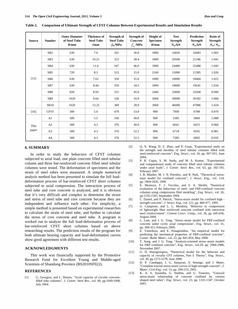
Based on the foregoing analysis results, one program
has been developed to simulate the full load-deformation
process of bar-reinforced CFST short columns under axial
compression. The simulation results of the longitudinal and
lateral strain of steel tube, and the comparison between the
simulation results and test results, are shown in Fig. (5). The
deformation comparison of two bar-reinforced CFST
columns between calculating results and experimental results
are shown in Fig. (6). Furthermore, some calculating and
experimental results of the ultimate bearing capacity of
CFST columns, including the ratio of calculating data to
testing data, are listed in Table 2.
Fig. (6). Comparison of deformation between simulations and tests
for (a) Specimen A2 and (b) Specimen A3.
It can been clearly seen from the comparison of
calculating results with experimental results that the method
presented to analyze the longitudinal and lateral strain of
steel tube is feasible and practicable. Moreover, the program
also has a good accuracy to simulate the load-deformation
process and calculate the ultimate bearing capacity of CFST
columns.
0.0 0.5 1.0 1.5 2.00
1000
2000
3000
4000
5000
6000
7000
test1 test2 test3 test4 prediction
Axial strain /%
Axi
al l
oad
/kN
specimen A2
(a)
0.0 0.5 1.0 1.5 2.00
1000
2000
3000
4000
5000
6000
7000
test1 test2 test3 test4 prediction
Axi
al lo
ad /k
N
Specimen A3
Axial strain /%
(b)
114 The Open Civil Engineering Journal, 2011, Volume 5 Han and Cong
6. SUMMARY
In order to study the behaviors of CFST columns
subjected to axial load, one plain concrete filled steel tubular
column and three bar-reinforced concrete filled steel tubular
columns were tested. The deformation of specimens and the
strain of steel tubes were measured. A simple numerical
analysis method has been presented to simulate the full load-
deformation process of bar-reinforced CFST short columns
subjected to axial compression. The interaction process of
steel tube and core concrete is analyzed, and it is obvious
that it’s very difficult and complex to determine the strain
and stress of steel tube and core concrete because they are
independent and influence each other. For simplicity, a
simple method is presented based on experimental researches
to calculate the strain of steel tube, and further to calculate
the stress of core concrete and steel tube. A program is
worked out to analyze the full load-deformation process of
bar-reinforced CFST short columns based on above
researching results. The prediction results of the program for
both ultimate bearing capacity and load-deformation curves
show good agreement with different test results.
ACKNOWLEDGMENTS
This work was financially supported by the Promotive
Research Fund for Excellent Young and Middle-aged
Scientists of Shandong Province (BS2010SF022).
REFERENCES
[1] G. Georgios, and L. Dennis, "Axial capacity of circular concrete-filled tube columns", J. Constr. Steel Res., vol. 60, pp.1049-1068,
July 2004.
[2] Q. X. Wang, D. Z. Zhao, and P. Guan, "Experimental study on
the strength and ductility of steel tubular columns filled with steel-reinforced concrete", Eng. Struct., vol. 26, pp. 907-915, June
2004. [3] P. K. Gupta, S. M. Sarda, and M. S. Kumar, "Experimental
and computational study of concrete filled steel tubular columns under axial loads", J. Constr. Steel. Res., vol. 63, pp. 182-193,
February 2007. [4] J. B. Mander, M. J. N. Priestley, and R. Park, "Theoretical stress-
stain model for confined concrete", J. Struct. Eng., vol. 114, pp. 1804-1826, 1998.
[5] E. Montoya, F. J. Vecchio, and S. A. Sheikh, "Numerical evaluation of the behaviour of steel- and FRP-confined concrete
columns using compression filed modeling", Eng. Struct., vol. 26, pp.1535-1545, September 2004.
[6] C. Daniel, and P. Patrick, "Stress-strain model for confined high -strength concrete", J. Struct. Eng., vol. 121, pp. 468-477, 1995.
[7] G. Campione, and L. L. Mendola, "Behavior in compression of lightweight fiber reinforced concrete confined with transverse
steel reinforcement", Cement Concr. Comp., vol. 26, pp. 645-656, August 2004.
[8] L. Lam, and J. G. Teng, "Stress–strain model for FRP-confined concrete under cyclic axial compression", Eng. Struct., vol. 31,
pp. 308-321, February 2009. [9] E. Vintzileou, and E. Panagiotidou, "An empirical model for
predicting the mechanical properties of FRP-confined concrete", Constr. Build. Mater., vol. 22, pp. 841-854, May 2008.
[10] T. Jiang, and J. G. Teng, "Analysis-oriented stress–strain models for FRP–confined concrete", Eng. Struct., vol.29, pp. 2968-2986,
November 2007. [11] G. D. Hatzigeorgiou, "Numerical model for the behavior and
capacity of circular CFT columns, Part I: Theory", Eng. Struct., vol. 30, pp.1573-1578, June 2008.
[12] D. P. Candappa, J. G. Sanjayan, S. Setunge, and J. Mater, "Complete triaxial stress-strain curves of high-strength concrete", J.
Mater. Civil Eng., vol. 13, pp. 209-215, 2001. [13] K. A. S. Susantha, G. Hanbin, and U. Tsutomu, "Uniaxial
stress-strain relationship of concrete confined by various shaped steel tubes", Eng. Struct., vol. 23, pp. 1331-1347, October
2001.
Table 2. Comparison of Ultimate Strength of CFST Columns Between Experimental Results and Simulation Results
Source Number
Outer Diameter
of Steel Tube
D/mm
Thickness of
Steel Tube
t/mm
Strength of
Steel Tube
fsk/MPa
Strength of
Concrete
fck /MPa
Height of
Specimen
H/mm
Test
Strength
Nue/kN
Prediction
Strength
Nuc/kN
Ratio of
Strength
Nuc/ Nue
SB2 630 7.0 291 36.0 1890 16650 16683 1.002
SB3 630 10.21 323 38.4 1890 20500 21346 1.041
SB4 630 11.6 347 46.0 1890 24400 25488 1.045
SB5 720 8.3 312 15.0 2160 15000 15385 1.026
SB6 630 7.61 350 35.0 1890 18000 18404 1.022
SB7 630 8.44 350 34.5 1890 18600 19241 1.034
SB8 820 8.93 331 45.0 2460 33600 33268 0.990
SB9 1020 9.64 336 16.9 3060 30000 30182 1.006
[15]
SB10 1020 13.25 369 28.9 3060 46000 47086 1.024
[16] CFST 300 5.0 478 53.0 900 7000 6788 0.970
A1 300 5.5 336 49.0 900 5385 5860 1.088
A2 300 4.3 376 49.0 900 6641 6415 0.966
A3 300 4.3 376 52.2 900 6718 6592 0.981
This
paper
A4 300 4.3 376 52.2 900 7385 6902 0.935
Experimental and Numerical Study on Bar-Reinforced Concrete Filled The Open Civil Engineering Journal, 2011, Volume 5 115
[14] W. P. Lokuge, J. G. Sanjayan, and S. Setunge, "Constitutive model
for confined high strength concrete subjected to cyclic loading", J. Mater. Civil Eng., vol. 16, pp. 297-305, 2004.
[15] C. D. Goode, "Concrete filled steel tubular columns-state of the art", Indus. Con., vol. 26, pp. 23-27, 1996 (in Chinese).
[16] C. M. Zhang, L. C. Wang, and Y. Yin, "Studies on axial
compressive experiments of several kinds of steel and high-strength concrete columns", J. Harbin Inst. Tech., vol. 36, pp. 1678-1682,
2004 (in Chinese).
Received: September 09, 2010 Revised: November 21, 2010 Accepted: January 26, 2011
© Han and Cong; Licensee Bentham Open.
This is an open access article licensed under the terms of the Creative Commons Attribution Non-Commercial License (http://creativecommons.org/licenses/ by-nc/3.0/) which permits unrestricted, non-commercial use, distribution and reproduction in any medium, provided the
work is properly cited.