Embed Size (px)
Citation preview
International Journal of Advanced Thermofluid Research Vol. 3, No. 1, 2017 ISSN 2455-1368 (Online)
Published by: International Research Establishment for Energy and Environment (IREEE), Kerala, India. (www.ijatr.org; www.ireee.net)
16
Experimental and Numerical Investigation of LPG Fuelled Inverse Diffusion Flame in a Coaxial Burner
Vipul Patel and Rupesh Shah*
Department of Mechanical Engineering, Sardar Vallabhbhai National Institute of Technology, Surat 395007, India
*Corresponding Author: E-mail: [email protected] Phone: +91-9824172452
Abstract: An experimental and numerical investigation of unconfined liquefied petroleum gas (LPG) fuelled inverse diffusion flame (IDF) is presented. The effect of air-fuel velocity ratio on the appearance of the LPG IDF are investigated. A fixed air jet velocity of Va = 11.31 m/s is chosen for the analysis, while the fuel jet velocity is varied from 0.014 m/s to 0.083 m/s. The observations indicate that the air-fuel jet velocity ratio has significant effect on the flame appearance of LPG IDF. It is found that the flame length increases with increase in fuel jet flow. Actual flame in burner is highly complex in nature as it involves momentum, mass and energy transfer in highly turbulent flow regime. To extract detailed information of flow physics, numerical analysis of LPG IDF is performed. It is observed that temperature along the centerline of IDF increases as distance from burner exit (Z) increases. This nature of temperature distribution indicates that the central cold air in the air jet is gradually heated toward the downstream of the IDF. The highest flame temperature is noticed at Z = 30 mm. The highest flame temperature predicted numerically at axial height of 30 mm is central portion of the blue zone of the flame which is main reaction zone. Keywords: Inverse diffusion flame; Flame appearance; Flame length; Coaxial burner.
1. Introduction
Domestic and commercial combustion systems generally employ premixed flame due to its relatively clean and rapid combustion characteristics. Premixed flame has narrow flammable limits hence limited stability. Inverse diffusion flame (IDF) is non-premixed diffusion flame. It is a unique kind of flame where high mass flow rate of inner air jet is surrounded by low mass flow rate of outer fuel jet. High momentum air jet ensures the entrainment of fuel into air jet and enhances mixing of fuel and air compared to normal diffusion flame (NDF). IDF possesses characteristics of wide range of stability, better operational safety and less emissions compared to NDF. Wu and Essenhigh (1984) described six different regimes of methane IDF, based on air-fuel velocities, visible appearance and temperature characteristics. Makofski et al. (2004) studied the effect of air flow variation on flame structure of methane and ethylene IDF using hydroxyl laser induced fluorescence with theoretical scale estimation. Zhen et al. (2011a) investigated the effect of nozzle length in multi jet fuel burner. They reported that the potential core and flame base were shorter with short nozzles compared to long nozzles. The effects of addition of natural gas and air on inverse flame structure were investigated by Sobiesiak and Wenzell (2005). Mahesh and

International Journal of Advanced Thermofluid Research Vol. 3, No. 1, 2017 ISSN 2455-1368 (Online)
Published by: International Research Establishment for Energy and Environment (IREEE), Kerala, India. (www.ijatr.org; www.ireee.net)
17
Mishra (2008 & 2010) carried out experiments on liquefied petroleum gas (LPG) IDF stabilized in backstep burner with different air-fuel ratios. Elbaz and Roberts (2014a) investigated the role of entrainment and mixing in methane IDF. Stelzner et al. (2013) performed experimental and numerical investigations of structure of rich methane IDF. Makofski et al. (2006) measured flame height of ethylene and methane IDF with planar laser-induced fluorescence of hydroxyl radicals. They observed a greater flame height of luminous zone than the reaction zone due to presence of luminous soot. Mahesh and Mishra (2011) compared LPG IDF in coaxial and recessed backstep burner. They observed more compact flame shape in the backstep burner. Elbaz and Roberts (2014b) characterized methane IDF, based on temperature distribution, flame height and emission characteristics. Sze et al. (2004) experimentally investigated heat flux and temperature distribution in butane IDF. Bhatia et al. (2012) numerically analyzed the effect of oxygen enrichment and gravity variation on flame structure of the IDF and NDF. Barakat et al. (2013) investigated the effects of jet dynamics and geometrical parameters of burner in LPG IDF. Sze et al. (2006) revealed that intense air-fuel mixing causes higher flame temperature in circumferentially arranged ports compared to coaxial arranged ports. Takagi et al. (1996) numerically analyzed the influence of preferential diffusion on the temperature characteristics of NDF and IDF. Dong et al. (2013) investigated heat transfer characteristics in butane IDF with different air-port diameters. Zhen et al. (2011b) investigated the influence of swirling on heat transfer characteristic in LPG IDF. Porous medium (PM) combustion is also an immersing technique for domestic and industrial burners due to higher burning rates with less pollutant emissions. Muhad et al. (2011) worked on enhancement of a partially premixed PM combustor. Abdul Mujeebu et al. (2013) carried out experimental and numerical studies on surface combustion in PM and developed a premixed PM burner which is suitable for normal household applications.
The objective of the present work is to examine the influence of air-fuel velocity ratio on the visible appearance of LPG IDF in a coaxial burner. In this respect the flame length, flame shape and structure is evaluated at different air-fuel velocity ratios. The experimental results are used in combination with numerical results of temperature profiles and velocity profiles to analyze the flame appearance and flame length.
2. Experimental Setup The coaxial burner used in the present work is shown in Figure 1 and Figure 2. The burner has concentric tubes with diameter ratio of 2.16. The burner consists of two coaxial tubes with inner tube of 13 mm diameter and outer tube of 28 mm diameter. With separately supplied air and fuel, the central air jet is surrounded by annular fuel jet. Figure 3 shows the photograph of the experimental setup. The air is supplied through the blower, while the fuel is supplied from LPG cylinder. The fuel and air flow rates are measured by calibrated rotameters (accuracy ± 2.0 % of full scale). LPG used as a fuel, contains 69% C4H10 (butane), 30% C3H8 (propane) and other trace of gases by volume. To prevent any disturbance from outside air, an enclosure with cross section 50 cm × 50 cm and height of 100 cm is used to surround the burner. The flame appearance of IDF is observed through a glass window provided at front side of the enclosure. Flame photographs are recorded by high resolution digital camera (24.2 megapixel). Ten photographs are taken for each IDF configuration. The

International Journal of Advanced Thermofluid Research Vol. 3, No. 1, 2017 ISSN 2455-1368 (Online)
Published by: International Research Establishment for Energy and Environment (IREEE), Kerala, India. (www.ijatr.org; www.ireee.net)
18
length of the flame is measured by an image processing software ImageJ (version 1.50i). Final flame length is determined by averaging of flame length measured from ten photographs. The flame length is defined as the distance between burner-exit to flame tip along the vertical centerline of IDF.
Air
Fuel
Outer tube
Inner tube
150 mm
Figure 1. Schematic of the coaxial burner Figure 2. Photograph of the coaxial burner
Figure 3. Experimental test setup.
3. Numerical investigation
Actual flame in burner is complex in nature as it involves momentum, mass and energy transfer in highly turbulent flow regime. To extract detailed information about temperature contours, temperature profiles and velocity profiles, numerical analysis is carried out. Three–dimensional domain of dimensions 0.5 m × 0.5 m × 1.5 m above burner exit is considered for numerical investigation (Figure 4 (a)). Unstructured mesh is generated in

International Journal of Advanced Thermofluid Research Vol. 3, No. 1, 2017 ISSN 2455-1368 (Online)
Published by: International Research Establishment for Energy and Environment (IREEE), Kerala, India. (www.ijatr.org; www.ireee.net)
19
this domain as shown in Figure 4(b). Mesh generation is accomplished with pre-processor GAMBIT. The air and fuel separately enter into the domain through bottom of the domain and products of combustion exit from the top of the domain. Air and fuel entry surfaces are defined as velocity inlets and outlet is define as pressure outlet (zero gauge pressure). Grid independence study is separately done to derive the grid independent size. The variation in the turbulent kinetic energy along the axis of the burner is considered as grid sensitivity parameter. Grid with total 1122083 elements is achieved as grid independent size. All reactive flow analysis is performed with this grid-independent size. FLUENT (ANSYS version 15.0.0) is used as processor for the simulation of the burner geometry. Continuity equation, momentum equations, equations related to k-ε turbulence model and Favre mean mixture fraction equation are used in solving present combustion problem numerically. The PDF (non-premixed combustion model) approach is used for the reaction modelling. PDF table is created for LPG as a fuel. In reactive flow analysis LPG is used as a fuel and the ratio of mole fractions of butane: propane taken is 0.7:0.3. In order to study variations in velocity and temperature, various stations have been considered at deferent axial locations in the domain.
(a) The geomety of domain (b) Meshed simulation model
Figure 4. Computation domain.
International Journal of Advanced Thermofluid Research Vol. 3, No. 1, 2017 ISSN 2455-1368 (Online)
Published by: International Research Establishment for Energy and Environment (IREEE), Kerala, India. (www.ijatr.org; www.ireee.net)
20
4. Results and Discussion
4.1 Temperature contours and flow properties along the domain
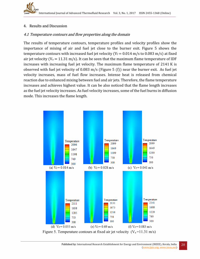
The results of temperature contours, temperature profiles and velocity profiles show the
importance of mixing of air and fuel jet close to the burner exit. Figure 5 shows the
temperature contours with increased fuel jet velocity (Vf = 0.014 m/s to 0.083 m/s) at fixed
air jet velocity (Va = 11.31 m/s). It can be seen that the maximum flame temperature of IDF
increases with increasing fuel jet velocity. The maximum flame temperature of 2141 K is
observed with fuel jet velocity of 0.083 m/s (Figure 5 (f)) near the burner exit. As fuel jet
velocity increases, mass of fuel flow increases. Intense heat is released from chemical
reaction due to enhanced mixing between fuel and air jets. Therefore, the flame temperature
increases and achieves highest value. It can be also noticed that the flame length increases
as the fuel jet velocity increases. As fuel velocity increases, some of the fuel burns in diffusion
mode. This increases the flame length.
Figure 5. Temperature contours at fixed air jet velocity (Va =11.31 m/s)

International Journal of Advanced Thermofluid Research Vol. 3, No. 1, 2017 ISSN 2455-1368 (Online)
Published by: International Research Establishment for Energy and Environment (IREEE), Kerala, India. (www.ijatr.org; www.ireee.net)
21
Figure 6 illustrates the temperature contour and actual flame appearance with Va = 11.31
m/s and Vf = 0.097 m/s. It can be observed that flame shape predicted numerically is
matching qualitatively with that obtained experimentally. The numerical results obtained in
terms of temperature profiles and velocity profiles are depicted in Figure 7 and Figure 8
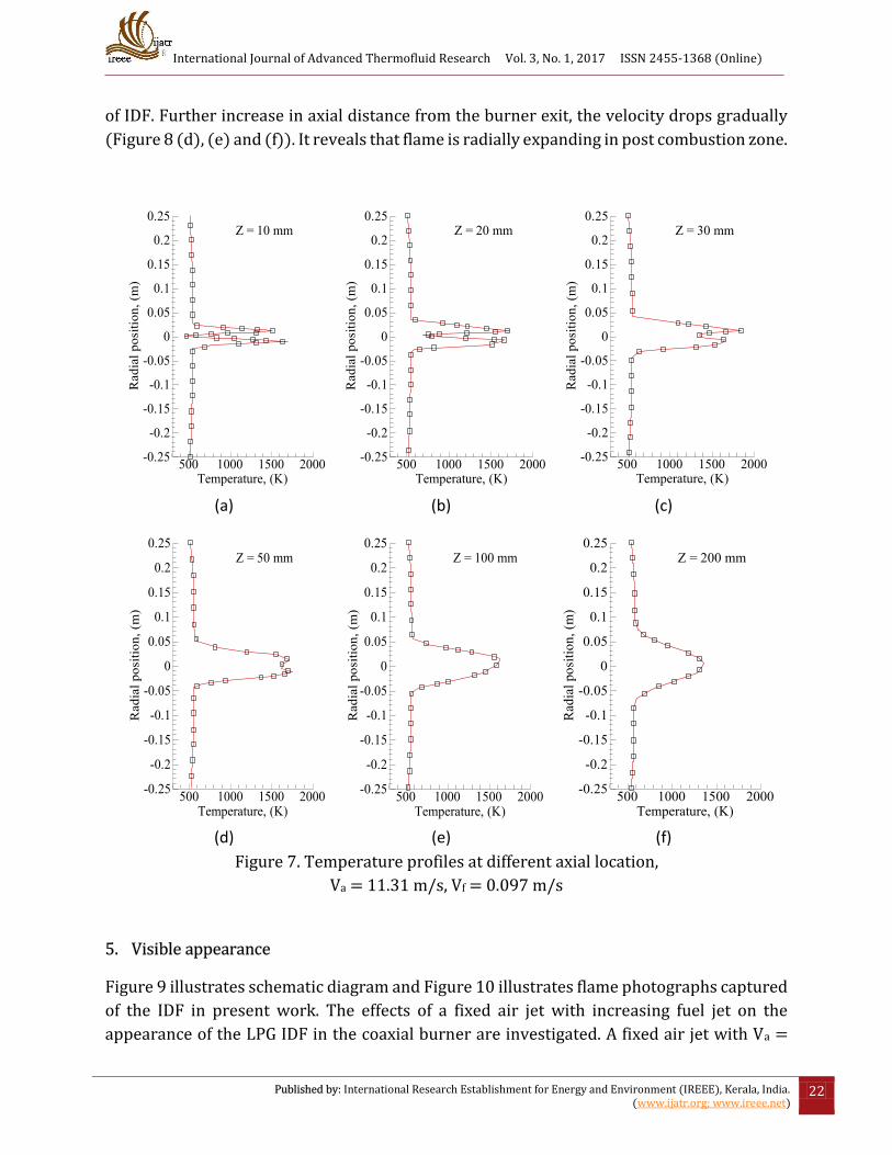
respectively. Figure 7 represents the temperature distribution at different axial locations. It
can be observed that the temperature along centerline of IDF increases as distance from
burner exit (Z) increases (Figure 7 (a), (b) and (c)). This nature of temperature distribution
indicates that the central cold air in the air jet is gradually heated toward the downstream of
the IDF. The highest flame temperature is noticed at Z = 30 mm (Figure 7(c)).
(a) (b)
Figure 6. Temperature contour and actual flame appearance,
Va = 11.31 m/s, Vf = 0.097 m/s.
The highest flame temperature predicted numerically at axial height of 30 mm is actually
central part of the blue region of the flame (Figure 6(b)). It is main reaction zone. In this zone
the mixing of air and fuel completes and heat releases due to chemical reactions. Further
increase in axial distance from the burner exit, the temperature along centerline drops
gradually (Figure 7 (d), (e) and (f)). It is post combustion zone, where the rate of heat release
decreases. Also the entrainment of cold air from the surroundings dilutes the hot products
which are released during combustion. Figure 8 illustrates the axial velocity distribution at
different axial locations. It can be observed that the maximum velocity is along the centerline
Temperature2144.02
1683.01
1222.01
761.004
300
International Journal of Advanced Thermofluid Research Vol. 3, No. 1, 2017 ISSN 2455-1368 (Online)
Published by: International Research Establishment for Energy and Environment (IREEE), Kerala, India. (www.ijatr.org; www.ireee.net)
22
of IDF. Further increase in axial distance from the burner exit, the velocity drops gradually
(Figure 8 (d), (e) and (f)). It reveals that flame is radially expanding in post combustion zone.
(a) (b) (c)
(d) (e) (f)
Figure 7. Temperature profiles at different axial location,
Va = 11.31 m/s, Vf = 0.097 m/s
5. Visible appearance
Figure 9 illustrates schematic diagram and Figure 10 illustrates flame photographs captured
of the IDF in present work. The effects of a fixed air jet with increasing fuel jet on the
appearance of the LPG IDF in the coaxial burner are investigated. A fixed air jet with Va =
Temperature, (K)
Rad
ialp
ositi
on,(
m)
500 1000 1500 2000-0.25
-0.2
-0.15
-0.1
-0.05
0
0.05
0.1
0.15
0.2
0.25Z = 10 mm
Temperature, (K)
Rad
ialp
ositi
on,(
m)
500 1000 1500 2000-0.25
-0.2
-0.15
-0.1
-0.05
0
0.05
0.1
0.15
0.2
0.25Z = 20 mm
Temperature, (K)
Rad
ialp
ositi
on,(
m)
500 1000 1500 2000-0.25
-0.2
-0.15
-0.1
-0.05
0
0.05
0.1
0.15
0.2
0.25Z = 30 mm
Temperature, (K)
Rad
ialp
ositi
on,(
m)
500 1000 1500 2000-0.25
-0.2
-0.15
-0.1
-0.05
0
0.05
0.1
0.15
0.2
0.25Z = 50 mm
Temperature, (K)
Rad
ialp
ositi
on,(
m)
500 1000 1500 2000-0.25
-0.2
-0.15
-0.1
-0.05
0
0.05
0.1
0.15
0.2
0.25Z = 100 mm
Temperature, (K)
Rad
ialp
ositi
on,(
m)
500 1000 1500 2000-0.25
-0.2
-0.15
-0.1
-0.05
0
0.05
0.1
0.15
0.2
0.25Z = 200 mm

International Journal of Advanced Thermofluid Research Vol. 3, No. 1, 2017 ISSN 2455-1368 (Online)
Published by: International Research Establishment for Energy and Environment (IREEE), Kerala, India. (www.ijatr.org; www.ireee.net)
23
11.31 m/s is chosen for analysis of variance in the IDFs under different fuel jets. The fuel jet
is varied from Vf = 0.014 m/s to 0.083 m/s, so that the influence of different fuelling rate can
be analyzed. The structure and shape of the IDF depends on the burner geometry, air flow
rate and fuel flow rate. The ratio between the momentums of air jet and fuel jet govern by
the air flow rate and fuel flow rate. At a constant fuel flow rate, the air jet momentum
increases with increase in air flow rate. At a constant air flow rate, the fuel jet momentum
increases with increase in fuel flow rate.
(a) (b) (c)
(d) (e) (f)
Figure 8. Velocity profiles at different axial location,
Va = 11.31 m/s, Vf = 0.097 m/s
Axial velocity, (m/s)
Radi
alpo
sitio
n,(m
)
-2 0 2 4 6 8 10 12 14-0.25
-0.2
-0.15
-0.1
-0.05
0
0.05
0.1
0.15
0.2
0.25Z = 10 mm
Axial velocity, (m/s)
Rad
ialp
ositi
on,(
m)
-2 0 2 4 6 8 10 12 14-0.25
-0.2
-0.15
-0.1
-0.05
0
0.05
0.1
0.15
0.2
0.25Z = 20 mm
Axial velocity, (m/s)
Radi
alpo
sitio
n,(m
)-2 0 2 4 6 8 10 12 14-0.25
-0.2
-0.15
-0.1
-0.05
0
0.05
0.1
0.15
0.2
0.25Z = 30 mm
Axial velocity, (m/s)
Rad
ialp
ositi
on,(
m)
-2 0 2 4 6 8 10 12 14-0.25
-0.2
-0.15
-0.1
-0.05
0
0.05
0.1
0.15
0.2
0.25Z = 50 mm
Axial velocity, (m/s)
Rad
ialp
ositi
on,(
m)
-2 0 2 4 6 8 10 12 14-0.25
-0.2
-0.15
-0.1
-0.05
0
0.05
0.1
0.15
0.2
0.25Z = 100 mm
Axial velocity, (m/s)
Rad
ialp
ositi
on,(
m)
-2 0 2 4 6 8 10 12 14-0.25
-0.2
-0.15
-0.1
-0.05
0
0.05
0.1
0.15
0.2
0.25Z = 200 mm

International Journal of Advanced Thermofluid Research Vol. 3, No. 1, 2017 ISSN 2455-1368 (Online)
Published by: International Research Establishment for Energy and Environment (IREEE), Kerala, India. (www.ijatr.org; www.ireee.net)
24
Flame torch
Flame base
Flame neck
Burner
Soot ring
FuelAir
Entrainment zone
Mixing and combustion zone
Figure 9. Schematic diagram of IDF.
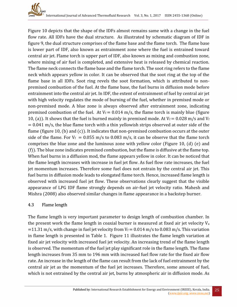
(a) (b) (c) (d) (e) (f)
Vf = 0.014 m/s Vf = 0.028 m/s Vf = 0.041 m/s Vf = 0.055 m/s Vf = 0.069 m/s Vf = 0.083 m/s
Figure 10. Flame photographs with increasing fuel jet velocity at fixed air jet velocity
(Va = 11.31 m/s).
International Journal of Advanced Thermofluid Research Vol. 3, No. 1, 2017 ISSN 2455-1368 (Online)
Published by: International Research Establishment for Energy and Environment (IREEE), Kerala, India. (www.ijatr.org; www.ireee.net)
25
Figure 10 depicts that the shape of the IDFs almost remains same with a change in the fuel
flow rate. All IDFs have the dual structure. As illustrated by schematic diagram of IDF in
figure 9, the dual structure comprises of the flame base and the flame torch. The flame base
is lower part of IDF, also known as entrainment zone where the fuel is entrained toward
central air jet. Flame torch is upper part of IDF, also known as mixing and combustion zone,
where mixing of air fuel is completed, and extensive heat is released by chemical reaction.
The flame neck connects the flame base and the flame torch. The soot ring refers to the flame
neck which appears yellow in color. It can be observed that the soot ring at the top of the
flame base in all IDFs. Soot ring revels the soot formation, which is attributed to non-
premixed combustion of the fuel. At the flame base, the fuel burns in diffusion mode before
entrainment into the central air jet. In IDF, the extent of entrainment of fuel by central air jet
with high velocity regulates the mode of burning of the fuel, whether in premixed mode or
non-premixed mode. A blue zone is always observed after entrainment zone, indicating
premixed combustion of the fuel. At Vf = 0.014 m/s, the flame torch is mainly blue (figure
10, (a)). It shows that the fuel is burned mainly in premixed mode. At Vf = 0.028 m/s and Vf
= 0.041 m/s, the blue flame torch with a thin yellowish strips observed at outer side of the
flame (figure 10, (b) and (c)). It indicates that non-premixed combustion occurs at the outer
side of the flame. For Vf = 0.055 m/s to 0.083 m/s, it can be observe that the flame torch
comprises the blue zone and the luminous zone with yellow color (Figure 10, (d) (e) and
(f)). The blue zone indicates premixed combustion, but the flame is diffusive at the flame top.
When fuel burns in a diffusion mod, the flame appears yellow in color. It can be noticed that
the flame length increases with increase in fuel jet flow. As fuel flow rate increases, the fuel
jet momentum increases. Therefore some fuel does not entrain by the central air jet. This
fuel burns in diffusion mode leads to elongated flame torch. Hence, increased flame length is
observed with increased fuel jet flow. These observations clearly suggest that the visible
appearance of LPG IDF flame strongly depends on air-fuel jet velocity ratio. Mahesh and
Mishra (2008) also observed similar changes in flame appearance in a backstep burner.
4.3 Flame length
The flame length is very important parameter to design length of combustion chamber. In
the present work the flame length in coaxial burner is measured at fixed air jet velocity Va
=11.31 m/s, with change in fuel jet velocity from Vf = 0.014 m/s to 0.083 m/s. This variation
in flame length is presented in Table 1. Figure 11 illustrates the flame length variation at
fixed air jet velocity with increased fuel jet velocity. An increasing trend of the flame length
is observed. The momentum of the fuel jet play significant role in the flame length. The flame
length increases from 35 mm to 196 mm with increased fuel flow rate for the fixed air flow
rate. An increase in the length of the flame can result from the lack of fuel entrainment by the
central air jet as the momentum of the fuel jet increases. Therefore, some amount of fuel,
which is not entrained by the central air jet, burns by atmospheric air in diffusion mode. As

International Journal of Advanced Thermofluid Research Vol. 3, No. 1, 2017 ISSN 2455-1368 (Online)
Published by: International Research Establishment for Energy and Environment (IREEE), Kerala, India. (www.ijatr.org; www.ireee.net)
26
a result, the flame length of IDF increases. It can be clearly noticed that the flame length
increases marginally from Vf = 0.055 m/s to 0.083 m/s. The flame torch consists of a blue
flame and a diffusion yellow flame. Further increase in fuel flow increases the flame length
of diffusion yellow flame mainly. This is because the flame becomes strong diffusional in
nature in the post combustion zone. This enhances the flame length rapidly. A similar trend
of flame length variation was reported by Mahesh and Mishra (2011) with backstep burner.
Table 1. Flame length variation at Va =11.31 m/s
Fuel jet velocity, Vf (m/s) Flame length, (mm)
0.014 35
0.028 53
0.041 70
0.055 83
0.069 132
0.083 196
Figure 11. Effect of fuel jet velocity on flame length.
6. Conclusion
Experimental investigation is carried out to observe flame appearance and flame length of
LPG IDF in a coaxial burner. The effects of a fixed air jet with increasing fuel jet on the
appearance and flame length of the LPG IDF are analyzed. The observations indicates that
the visible appearance of LPG IDF strongly depends on air-fuel jet velocity ratio. The
numerical analysis of LPG IDF is performed. Temperature contours, temperature profiles
International Journal of Advanced Thermofluid Research Vol. 3, No. 1, 2017 ISSN 2455-1368 (Online)
Published by: International Research Establishment for Energy and Environment (IREEE), Kerala, India. (www.ijatr.org; www.ireee.net)
27
and velocity profiles shows the importance of air and fuel jet mixing close to the burner exit.
The Following results are obtained from the present work.
The LPG IDF is observed with dual structure, the entrainment zone followed by
mixing and combustion zone. These two zones are separated by flame neck. A blue
zone is always observed after entrainment zone, indicating premixed combustion of
the fuel. The shape of the LPG IDFs almost remains same with a change in the fuel
flow rate.
The soot ring with yellow color is always noticed at the flame neck in all IDFs. At the
flame base, the fuel burns in diffusion mode before entrainment into the central air
jet. Soot ring revels the soot formation, which is attributed to non-premixed
combustion of the fuel.
At a fixed air flow rate with Va = 11.31 m/s, when fuel flow rate is increased from Vf
= 0.014 m/s to 0.083 m/s, the flame length gets elongated from 35 mm to 196 mm.
The flame changes from bluish to yellowish in mixing and combustion zone. This
indicates that the flame changes from premixed combustion to non-premixed
combustion. As fuel jet momentum increases, some fuel does not entrain by the
central air jet and burns in diffusion mode. As a reults, the length of the flame torch
increases, and hence, increased flame length is observed.
It can be clealy noticed that the flame length insreases marginally from Vf = 0.055
m/s to 0.083 m/s. However, the flame torch is consist of a blue flame and a diffusion
yellow flame but further increase in fuel flow increasese the flame length of diffusion
yellow flame mainly. This is because of the flame becomes diffusional in nature
stongly in the post combustion zone.
References
Abdul Mujeebu M, Abdullah MZ, Zuber M. (2013). Experiment and simulation to develop
clean porous medium surface combustor using LPG, ISI Bilimi ve Teknigi Dergisi-Journal of
Thermal Science and Technology; 33 (1): 55-61.
Barakat HZ, Salem MR, Morgan A, Hany HE. (2013). Study of effects of burner configuration
and jet dynamics on characteristics of inversed diffusion flames. Journal of Mechanical
Engineering Research, 5(7), pp. 128-144.
Bhatia P, Katta VR, Krishnan SS, Zheng Y, Sunderland PB, Gore JP. (2012). Simulations of
normal and inverse laminar diffusion flames under oxygen enhancement and gravity
variation. Combustion Theory and Modelling, 16, pp. 774-798.
Dong LL, Cheung CS, Leung CW. (2013). Heat transfer optimization of an impinging port-
array inverse diffusion flame jet. Energy, 49, pp. 182-192.

International Journal of Advanced Thermofluid Research Vol. 3, No. 1, 2017 ISSN 2455-1368 (Online)
Published by: International Research Establishment for Energy and Environment (IREEE), Kerala, India. (www.ijatr.org; www.ireee.net)
28
Elbaz AM, Roberts, WL. (2014a). Flame structure of methane inverse diffusion flame.
Experimental Thermal and Fluid Science, 56, pp. 23–32.
Elbaz AM, Roberts WL. (2014b). Experimental characterization of methane inverse diffusion
flame. Combustion Science and Technology, 186, pp. 1249–1272.
Mahesh S, Mishra DP. (2008). Flame stability and emission characteristics of turbulent LPG
IDF in a backstep burner. Fuel, 87, pp. 2614–2619.
Mahesh S, Mishra DP. (2010). Flame structure of LPG-air inverse diffusion flame in a
backstep burner. Fuel, 89, pp. 2145–2148.
Mahesh S, Mishra DP (2011). Study of the turbulent inverse diffusion flame in recessed
backstep and coaxial burners, Combustion, Explosion and Shock Waves, 47 (3), pp. 274–279.
Mikofski MA, Williams TC, Shaddix CR, Blevins LG. (2004). Effect of varied air flow on flame
structure of laminar inverse diffusion flame. Combustion Institute, 04S-7.
Mikofski MA, Williams TC, Shaddix CR and Blevins LG. (2006). Flame height measurement of
laminar inverse diffusion flames. Combustion and Flame, 146, pp. 63–72.
Muhad RMN, Abdullah MZ, Abdul Mujeebu M, Abu Bakar MZ Zakaria R, Mohamad AA (2011).
The development and performance analysis of partially premixed LPG porous medium
combustor, Energy Sources, Part A, 33 pp. 1260–1270.
Sobiesiak A, Wenzell JC. (2005). Characteristics and structure of inverse diffusion flames on
natural gas. Proceedings of the Combustion Institute, 30, pp. 743-749.
Stelzner B, Hunger F, Voss S, Keller J, Hasse C, Trimis D. (2013). Experimental and numerical
study of rich inverse diffusion flame structure. Proceedings of the Combustion Institute, 34,
pp. 1045–1055.
Sze LK, Cheung CS and Leung CW (2004). Temperature distribution and heat transfer
characteristics of an inverse diffusion flame with circumferentially arranged fuel ports.
International Journal of Heat and Mass Transfer, 47, pp. 3119–3129.
Sze LK, Cheung CS, Leung CW. (2006). Appearance, temperature, and NOx emission of two
inverse diffusion flames with different port design. Combustion and Flame, 144, pp. 237–
248.
Takagi T, Xu Z, Komiyama M. (1996). Preferential diffusion effects on the temperature in
usual and inverse diffusion flames. Combustion and Flame, 106, pp. 252-260.
Wu KT and Essenhigh RH. (1984). Mapping and structure of inverse diffusion flame of
methane. The combustion Institute, pp. 1925-1932.

International Journal of Advanced Thermofluid Research Vol. 3, No. 1, 2017 ISSN 2455-1368 (Online)
Published by: International Research Establishment for Energy and Environment (IREEE), Kerala, India. (www.ijatr.org; www.ireee.net)
29
Zhen HS, Choy YS, Leung CW, Cheung CS. (2011a). Effects of nozzle length on flame and
emission behaviours of multi-fuel-jet inverse diffusion flame burner. Applied Energy, 88, pp.
2917–2924.
Zhen HS, Leung CW, Cheung CS. (2011b). Emission of impinging swirling and non-swirling
inverse diffusion flames, Applied Energy, 88, pp. 1629–1634.